EP2921385A1 - Saddle-ride-type vehicle - Google Patents
Saddle-ride-type vehicle Download PDFInfo
- Publication number
- EP2921385A1 EP2921385A1 EP15156863.1A EP15156863A EP2921385A1 EP 2921385 A1 EP2921385 A1 EP 2921385A1 EP 15156863 A EP15156863 A EP 15156863A EP 2921385 A1 EP2921385 A1 EP 2921385A1
- Authority
- EP
- European Patent Office
- Prior art keywords
- wall
- heat shielding
- battery
- undercover
- saddle
- Prior art date
- Legal status (The legal status is an assumption and is not a legal conclusion. Google has not performed a legal analysis and makes no representation as to the accuracy of the status listed.)
- Granted
Links
Images



Classifications
-
- B—PERFORMING OPERATIONS; TRANSPORTING
- B62—LAND VEHICLES FOR TRAVELLING OTHERWISE THAN ON RAILS
- B62K—CYCLES; CYCLE FRAMES; CYCLE STEERING DEVICES; RIDER-OPERATED TERMINAL CONTROLS SPECIALLY ADAPTED FOR CYCLES; CYCLE AXLE SUSPENSIONS; CYCLE SIDECARS, FORECARS, OR THE LIKE
- B62K11/00—Motorcycles, engine-assisted cycles or motor scooters with one or two wheels
- B62K11/02—Frames
- B62K11/10—Frames characterised by the engine being over or beside driven rear wheel
-
- B—PERFORMING OPERATIONS; TRANSPORTING
- B62—LAND VEHICLES FOR TRAVELLING OTHERWISE THAN ON RAILS
- B62J—CYCLE SADDLES OR SEATS; AUXILIARY DEVICES OR ACCESSORIES SPECIALLY ADAPTED TO CYCLES AND NOT OTHERWISE PROVIDED FOR, e.g. ARTICLE CARRIERS OR CYCLE PROTECTORS
- B62J43/00—Arrangements of batteries
- B62J43/10—Arrangements of batteries for propulsion
- B62J43/16—Arrangements of batteries for propulsion on motorcycles or the like
-
- B—PERFORMING OPERATIONS; TRANSPORTING
- B62—LAND VEHICLES FOR TRAVELLING OTHERWISE THAN ON RAILS
- B62J—CYCLE SADDLES OR SEATS; AUXILIARY DEVICES OR ACCESSORIES SPECIALLY ADAPTED TO CYCLES AND NOT OTHERWISE PROVIDED FOR, e.g. ARTICLE CARRIERS OR CYCLE PROTECTORS
- B62J43/00—Arrangements of batteries
- B62J43/20—Arrangements of batteries characterised by the mounting
- B62J43/28—Arrangements of batteries characterised by the mounting hidden within the cycle frame
-
- B—PERFORMING OPERATIONS; TRANSPORTING
- B62—LAND VEHICLES FOR TRAVELLING OTHERWISE THAN ON RAILS
- B62K—CYCLES; CYCLE FRAMES; CYCLE STEERING DEVICES; RIDER-OPERATED TERMINAL CONTROLS SPECIALLY ADAPTED FOR CYCLES; CYCLE AXLE SUSPENSIONS; CYCLE SIDECARS, FORECARS, OR THE LIKE
- B62K2202/00—Motorised scooters
Definitions
- the present invention relates to a saddle-ride-type vehicle provided with a step on which a rider places his feet and an undercover which covers the step from below.
- a fuel tank (40) (numeral with a parenthesis indicating a symbol described in JP-A-2013-193641 , the same definition being applicable hereinafter) is arranged behind a radiator (41) in the longitudinal direction of the vehicle. It is not desirable that hot air discharged from the radiator (41) directly reaches the fuel tank (40).
- an intermediate wall (273d) is provided in front of the fuel tank (40), a gap is formed between the intermediate wall (273d) and the fuel tank (40), and cold air (traveling air which does not pass through the radiator) is made to flow through the gap as indicated by arrows (A1 to A4) thus shielding heat.
- the invention according to claim 1 is directed to a saddle-ride-type vehicle provided with a seat on which a rider is seated, a step which supports legs of the rider, and an undercover which covers the step from below, wherein an electric component is arranged below a tread surface of the step and above the undercover, a high-temperature component having a higher temperature than the electric component is arranged at a position above the undercover, and a hollow heat shielding wall having a front wall portion and a rear wall portion formed behind the front wall portion in a spaced-apart manner is formed on the undercover in an upwardly projecting manner.
- the hollow heat shielding wall includes left and right side wall portions which respectively connect left and right end portions of the front wall portion and left and right end portions of the rear wall portion to each other, and a ceiling which connects an upper end of the front wall portion, an upper end of the rear wall portion and upper ends of the left and right side wall portions to each other.
- the high-temperature component is a radiator arranged between a front wheel and the electric component, a discharge air opening portion which guides discharged air from the radiator is formed in the undercover, and at least a portion of the hollow heat shielding wall is arranged adjacent to the discharge air opening portion.
- the saddle-ride-type vehicle includes a power unit which is swingably supported at one side of a vehicle body center line, the electric component is a battery, the battery is arranged in an offset manner toward the other side with respect to the vehicle body center line, and the hollow heat shielding wall is disposed only in front of the battery in the longitudinal direction of the vehicle.
- the step includes a battery storing recessed portion which opens upwardly and stores the battery therein, and a lid which closes the battery storing recessed portion.
- At least one of the front wall portion and the rear wall portion is a stepped wall.
- the high-temperature component is a vehicle drive source arranged behind the electric component in the longitudinal direction of the vehicle.
- the invention according to claim 8 is directed to a saddle-ride-type vehicle provided with a seat on which a rider is seated, a step which supports legs of the rider, and an undercover which covers the step from below, wherein an electric component is arranged below a tread surface of the step and above the undercover, a high-temperature component having a higher temperature than the electric component is arranged at a position above the undercover, the step includes a battery storing recessed portion which opens upwardly and stores the battery therein, and a spaced-apart wall which is spaced apart from at least one of a front wall and a rear wall which form the battery storing recessed portion, and a hollow heat shielding wall which forms an air layer between the hollow heat shielding wall and the front wall or the rear wall is provided.
- the spaced-apart wall is connected to the step by way of a bendable movable portion, and the hollow heat shielding wall is configured such that an open end of a peripheral wall formed on an outer periphery of the spaced-apart wall is brought into contact with the front wall or the rear wall.
- the front wall portion and the rear wall portion exhibit a heat shielding action and, in addition to such an action, an air layer formed between the front wall portion and the rear wall portion exhibits a heat insulation action. Accordingly, heat shielding effect can be largely increased. Since traveling air is not positively used, there is no outstanding difference in a heat shielding effect between during traveling and during parking whereby a sufficient heat shielding action can be acquired even during parking.
- the hollow heat shielding wall can be integrally formed with the undercover and hence, it is possible to suppress the increase of the number of parts.
- the hollow heat shielding wall further includes the ceiling. Leakage of air in the upward direction can be prevented by the ceiling and hence, air stagnates in the inside of the hollow heat sealing wall whereby a heat insulating effect can be increased. Further, the hollow heat sealing wall is closed by the ceiling and hence, pebbles or mud water splashed up from a road minimally enter the inside of the undercover.
- the high-temperature component is the radiator arranged between the front wheel and the electric component. Since high-temperature discharge air from the radiator is shielded by the hollow heat shielding wall having a large heat shielding effect, it is possible to favorably protect electric component.
- the discharge air opening portion is formed in the undercover and hence, there is a possibility that rigidity is lowered due to the provision of the discharge air opening portion.
- the hollow heat shielding wall is provided adjacent to the discharge air opening portion and rigidity of the hollow heat shielding wall is high and hence, the undercover can maintain rigidity as a whole.
- the electric component is a battery
- the battery is arranged in an offset manner toward the other side with respect to the vehicle body center line and hence, the hollow heat shielding wall is provided only in front of the battery in the longitudinal direction of the vehicle.
- the improvement of the lateral balance can be increased.
- the hollow heat shielding wall is made of a resin, a resin material can be saved.
- the step includes the battery storing recessed portion which opens upwardly and stores a battery therein, and the lid which closes the battery storing recessed portion.
- the battery is shielded from heat by the wall of the battery storing recessed portion in addition to the hollow heat shielding wall and hence, a heat shielding effect can be further increased.
- At least one of the front wall portion and the rear wall portion is a stepped wall.
- the stepped wall can increase rigidity compared to a flat wall.
- the high-temperature component is the vehicle drive source arranged behind the electric component in the longitudinal direction of the vehicle. Since heat generated by an internal combustion engine or a traveling electric motor is shielded by the hollow heat shielding wall having a large heat shielding effect, an electric component can be favorably protected.
- the spaced-apart wall exhibits a heat shielding action and, further, the air layer sealed in the hollow heat shielding wall exhibits a heat insulating action. Accordingly, a heat shielding effect can be largely increased. Since traveling air is not positively used, no outstanding difference in a heat shielding effect is generated between during traveling and during parking whereby the spaced-apart wall can exhibit a sufficient heat shielding action even during parking.
- the hollow heat shielding wall is disposed not on the undercover but on a battery storing recessed portion side and hence, the undercover can be formed into a flat structure.
- the hollow heat shielding wall is connected to the step by way of the movable part and hence, the hollow heat shielding wall and the battery storing recessed portion can be integrally formed with each other and hence, a manufacturing cost can be decreased.
- a saddle-ride-type vehicle 10 is a two-wheeled vehicle which travels using a rear wheel 21 as a drive wheel.
- a front fork 12 which incorporates a front cushion therein is steerably supported on a head pipe 11.
- a front wheel 13 is rotatably mounted on a lower portion of the front fork 12.
- a steering handle 14 is mounted on an upper portion of the front fork 12.
- a down frame 15 is extended from the head pipe 11.
- a lower frame 16 is extended rearwardly in the longitudinal direction of the vehicle from a lower end of the down frame 15.
- a seat frame 17 is extended rearwardly in the longitudinal direction of the vehicle from a rear portion of the lower frame 16.
- a power unit 19 is extended rearwardly in the longitudinal direction of the vehicle from the rear portion of the lower frame 16 by way of a pivot shaft 18.
- the rear wheel 21 is supported on a rear portion of the power unit 19.
- An upper portion of a rear cushion 22 which is extended upwardly from the rear portion of the power unit 19 is connected to the seat frame 17.
- the saddle-ride-type vehicle 10 includes: a seat 23 and a rear storage part 24 referred to as a top box which are supported on the seat rail 17; a luggage box 25 and a fuel tank 26 which are arranged below the seat 23; a radiator 27 which constitutes a high-temperature member and is arranged between the front wheel 13 and the seat 23; and a hollow partition wall 60 and a battery 28 constituting an electric component which are arranged behind the radiator 27.
- the saddle-ride-type vehicle 10 further includes a floor-shaped step 31 which supports feet of the rider in front of and below the seat 23 on which the rider is seated, and an undercover 32 which covers the step 31 from below.
- the saddle-ride-type vehicle 10 includes: left and right under side covers 33 which close a gap formed between the step 31 and the undercover 32; a front cover 34 which is disposed in front of the step 31 and behind the front wheel 13; the battery 28 which is disposed at a position surrounded by the step 31, the undercover 32, and the left and right undercovers 33; and a rear cover 36 and the power unit 19 which are disposed behind the step 31.
- the steering handle 14 and meters 37 are arranged in front of the step 31 in the longitudinal direction of the vehicle.
- the step 31 includes a lid 38 on a center portion thereof.
- the lid 38 can be removed from the step 31 by loosening screws 39, 39.
- An upper surface of the lid 38 is formed coplanar with an upper surface of the step 31.
- the upper surface of the step 31 forms a tread surface on which the rider places his feet.
- the power unit 19 which is a heavy object is arranged on a left side in the vehicle width direction with respect to a vehicle body center line 41, and the battery 28 is arranged on a right side in the vehicle width direction with respect to the vehicle body center line 41. Accordingly, the balance is taken between the left side and the right side.
- the battery 28 which forms an electric component is arranged at a position offset on a right side with respect to the vehicle body center line (center line in the vehicle width direction) 41 (on a side opposite to the power unit 19), and fuse boxes 42, 42, a coupler 43, a harness 44 are arranged on a left side with respect to the vehicle body center line 41.
- the battery 28 is fixed to the step 31 using a strip-shaped band 45.
- a small sub lid 46 is mounted on the step 31 on a left side in the vehicle width direction.
- the sub lid 46 is a lid which covers a radiator cooling liquid filling port 47 disposed below the sub lid 46.
- a distance L exists between the vehicle body center line 41 and a center line 48 of the battery 28. That is, the battery 28 is arranged in an offset manner on a right side in the vehicle width direction with respect to the vehicle body center line 41. The battery 28 is heavy compared to the fuse box 42 and the like. By arranging the power unit ( Fig. 3 , symbol 19) on a side opposite to the battery 28, the saddle-ride-type vehicle 10 can take the balance in weight in the left and right directions between the power unit 19 and the battery 28.
- the fuse boxes 42, 42 and the coupler 43 are arranged on a left side in the vehicle width direction with respect to the vehicle body center line 41.
- the battery 28, the fuse boxes 42, 42, the coupler 43 and the harness 44 are efficiently housed in the center of the step 31 whose volume and area are limited.
- the step 31 includes a battery storing recessed portion 51 and a recessed portion 52 for storing electric articles at the center in the vehicle width direction.
- the battery storing recessed portion 51 largely projects downwardly.
- the recessed portion 52 for storing electric articles projects downwardly but not as much as the battery storing recessed portion 51.
- the undercover 32 is a resin-molded product having a relatively shallow dish shape.
- the undercover 32 has a hook 53 on a distal end thereof.
- the undercover 32 also has a hollow heat shielding wall 60 which projects upwardly on a portion thereof behind the hook 53 in the longitudinal direction of the vehicle.
- the undercover 32 further includes ribs 54 which project upwardly slightly behind the hollow heat shielding wall 60 and are brought into contact with the battery storing recessed portion 51 indicated by an imaginary line.
- a space is defined between the battery storing recessed portion 51 and the undercover 32 by the ribs 54. That is, a gap defined between the step 31 indicated by an imaginary line and the undercover 32 indicated by a solid line is closed by under side covers ( Fig. 2 , symbol 33).
- the undercover 32 includes: hooks 53, 53 on a front portion thereof.
- the undercover 32 also includes the ribs 54, 54 on left and right sides thereof at an approximately center position in the longitudinal direction.
- the undercover 32 further includes the large hollow heat shielding wall 60 in front of the right rib 54.
- the undercover 32 still further includes a large number of discharge air opening portions 55 in front of the hollow heat shielding wall 60 in the longitudinal direction of the vehicle and on a left side of the hollow heat shielding wall 60.
- the hollow heat shielding wall 60 is a box-shaped body or a cylindrical body constituted of a plurality of wall portions and has sufficient rigidity.
- the hollow heat shielding wall 60 is formed along the discharge air opening portions 55 and hence, the rigidity of the undercover 32 can be maintained although the discharge air opening portions 55 are formed.
- a front portion of the undercover 32 is supported by hooking the hook 53 on the front lower cross frame 71.
- the step 31 includes the battery storing recessed portion 51 and the removable lid 38.
- the battery 28 stored in the battery storing recessed portion 51 can be inspected by opening the lid 38. That is, the battery 28 is arranged between a tread surface of the step 31 (the surface at the same level as an upper surface of the lid 38) and the undercover 32.
- the undercover 32 includes the hollow heat shielding wall 60 as an integral part thereof.
- the hollow heat shielding wall 60 includes, at least, a front wall portion 61 and a rear wall portion 62 which is formed in a spaced-apart manner from the front wall portion 61.
- the hollow heat shielding wall 60 more preferably, includes: left and right side wall portions 63 which respectively connect left and right end portions of the front wall portion 61 and left and right end portions of the rear wall portion 62 to each other; and a ceiling 64.
- the hollow heat shielding wall 60 is still more preferably formed such that the front wall portion 61 is formed into a stepped shape.
- the front wall portion 61 is formed into a stepped wall which is constituted of: a horizontal portion 65 which corresponds to a tread surface of a step; an upper wall portion 66 which is raised from the horizontal portion 65; and a lower wall portion 67 which extends downwardly from the horizontal portion 65. Due to a space S defined by the front wall portion 61, the rear wall portion 62, the left and right side wall portions 63 and the ceiling wall 64, a heat shielding effect can be increased.
- the stepped wall can increase rigidity compared to a flat wall and hence, the stepped wall can contribute to the increase of rigidity of the whole undercover 32.
- the front wall portion 61 has the stepped shape and hence, the front wall portion 61 can be arranged close to the cross member 68.
- the horizontal portion 65 of the stepped wall is formed along the curve of a pipe of the cross member 68 and hence, the frame can be used also as a rigid member for the cover.
- the hollow heat shielding wall 60 having the above-mentioned structure is arranged such that the hollow heat shielding wall 60 projects upwardly between the radiator 27 disposed right behind the front wheel 13 and the battery 28.
- a plurality of air introducing opening portions 72 which introduce traveling air are formed in the front cover 34 arranged in front of the radiator 27 in the longitudinal direction of the vehicle in a state where the plurality of air introducing opening portions 72 are arranged in the vertical direction. Traveling air which passes through the air introducing opening portions 72 cools the radiator 27, while the traveling air per se is heated and becomes discharge air. The discharge air flows toward a rear side of the vehicle, and is discharged mainly from the discharge air opening portions 55.
- the radiator 27 is at a higher temperature than the battery 28 and hence, heat which the radiator 27 generates moves toward the battery 28.
- An air layer (space S) exists between the front wall portion 61 and the rear wall portion 62, and this air layer exhibits the favorable heat shielding performance.
- the front wall portion 61, the rear wall portion 62 and the front wall 51a of the battery storing recessed portion 51 form a heat shielding wall and exhibit a favorable heat shielding action. As a result, the increase of a temperature of the battery 28 can be suppressed.
- a width of the hollow heat shielding wall 60 in the vehicle width direction ( Fig. 8 , symbol L2) is equal to a width of the battery 28 in the vehicle width direction.
- the ceiling 64 of the hollow heat shielding wall 60 may be omitted, it is preferable to provide the ceiling 64.
- the ceiling 64 By providing the ceiling 64, there is no possibility that heated air is leaked upwardly. Since there is no movement of air (the movement of air being small even when air moves), the convective heat transfer can be suppressed so that the heat shielding performance can be increased. Additionally, since heat is shielded by the ceiling 64, there is no possibility that flying pebbles or mud water enters the inside of the undercover 32 thorough the hollow heat shielding wall 60.
- a rear hollow heat shielding wall 60F may be provided behind the battery 28. Due to the provision of the rear hollow heat shielding wall 60F, it is possible to shield heat which is directed toward the battery 28 from the vehicle drive source 73.
- hollow heat shielding wall 60 in front of the battery 28 and the rear hollow heat shielding wall 60F behind the battery 28 respectively.
- the hollow heat shielding walls 60, 60F are mounted on the undercover 32.
- the hollow heat shielding walls 60, 60F may be mounted on the battery storing recessed portion 51. A specific example of this case is explained hereinafter.
- the battery storing recessed portion 51 is integrally formed with the step 31, and the rear hollow heat shielding wall 60F is connected to at least one of the front wall 51a and a rear wall 51b (in this embodiment, the rear wall 51b) which forms the battery storing recessed portion 51 by way of a bendable movable portion 75.
- the rear hollow heat shielding wall 60F is formed simultaneously with the step 31 by a resin injection molding method.
- the rear hollow heat shielding wall 60F is constituted of a spaced-apart wall 76, a peripheral wall 77 which is raised from the spaced-apart wall 76, and a tongue member 78 which is formed on a portion of the rear hollow heat shielding wall 60F remotest from the movable portion 75.
- a hole 79 having an approximately 5mm is formed in the tongue member 78.
- a projection 81 which projects downwardly from the spaced-apart wall of the battery storing recessed portion 51 is fitted in the hole 79.
- the movable portion 75 is formed as a fragile portion having a thickness smaller than a thicknesses of other portions so that the movable portion 75 can be easily bent. Accordingly, by bending the movable portion 75 by an approximately 90°, as indicated by an imaginary line, an open end of the peripheral wall 77 is brought into contact with the rear wall 51b. The tongue member 78 is engaged with the projection 81. It is sufficient that the movable portion 75 is formed of a hinge and hence, another hinge structure may be adopted as the movable portion 75 besides the case where the movable portion 75 is formed of the small wall thickness member.
- the rear hollow heat shielding wall 60F is interposed between the battery 28 and the vehicle drive source 73.
- the spaced-apart wall 76 is arranged parallel to the rear wall 51b, and air existing between the spaced-apart wall 76 and the rear wall 51b is substantially sealed by the peripheral wall 77. The flow of air is suppressed and hence, the heat insulation performance can be increased.
- the rear hollow heat shielding wall 60F is connected to the rear wall 51b by way of the movable portion 75.
- the movable portion 75 may be omitted. That is, a pentahedron rear hollow heat shielding wall 60F which is formed of the spaced-apart wall 76 and the peripheral wall 77 may be prepared as a separate part, and the separate part may be fixed to the rear wall 51b using an adhesive agent or screws.
- the rear hollow heat shielding wall 60F may be formed of only the spaced-apart wall 76 which is spaced apart from the rear wall 51b while omitting the peripheral wall 77.
- the flow-in and the flow-out of air can be suppressed so that a heat insulation action can be increased.
- the hollow heat shielding wall 60 may be also attached to the front wall 51a. As a result of attaching the hollow heat shielding wall 60 in this manner, the undercover 32 becomes substantially flat. By forming the undercover 32 into a flat shape, traveling air is minimally entangled and hence, the undercover 32 having a flat shape is preferable from this point.
- the electric components indicate electric or electronic components in general which are relatively easily affected by heat such as a circuit board having an electronic circuit and the like besides the battery 28 and the fuse box 26 exemplified in the embodiment.
- vehicle drive source 73 any kind of vehicle drive sources may be used provided that the vehicle drive source is a drive source which generates a drive force for making a vehicle travel such as a gasoline engine, an electric motor, or a hydraulic motor.
- the drive source generates heat and hence, the drive source corresponds to a high-temperature component.
- hollow heat shielding walls 60, 60F are integrally formed with the undercover 32 by integral molding
- the hollow heat shielding walls 60, 60F may be formed integrally with the undercover 32 by posteriorly mounting the hollow heat shielding walls 60, 60F on the undercover 32 by using screws, by ultrasonic vibration fusing or the like.
- the battery storing recessed portion 51 is formed on the step 31.
- the structure where the battery 28 is arranged between the step 31 and the undercover 32 in a state where the battery 28 is supported on a bracket which extends from the vehicle body frame it is possible to prevent the weight of the battery 28 from being applied to the step 31.
- the invention is applicable to a saddle-ride-type vehicle where a floor-shaped step is disposed in front of a seat.
Landscapes
- Engineering & Computer Science (AREA)
- Mechanical Engineering (AREA)
- Automatic Cycles, And Cycles In General (AREA)
- Body Structure For Vehicles (AREA)
- Arrangement Or Mounting Of Propulsion Units For Vehicles (AREA)
Abstract
Description
- The present invention relates to a saddle-ride-type vehicle provided with a step on which a rider places his feet and an undercover which covers the step from below.
- Various types of saddle-ride-type vehicles where a rider is seated on a seat in a straddling manner and places his feet on steps, and travels the vehicle have been practically used. Further, there has been known a saddle-ride-type vehicle which is configured such that a radiator is arranged on a front side of the vehicle and a lower portion of the vehicle is covered with an undercover (see
JP-A-2013-193641 - As shown in Fig. 20 of
JP-A-2013-193641 JP-A-2013-193641 JP-A-2013-193641 - Although a traveling air can be acquired during traveling, during parking or low speed traveling, expected traveling air cannot be acquired. As a result, there has been a demand for the structure which has higher heat shielding effect.
- Assuming that a heat shielding member is added, the number of parts is increased so that a parts cost is increased. Under a current situation where the reduction of cost is required, the increase of the number of parts is not desirable.
- Accordingly, there has been a demand for a saddle-ride-type vehicle which can suppress the increase of the number of parts while increasing a heat shielding effect.
- It is an object of the invention to provide a saddle-ride-type vehicle which can suppress the increase of the number of parts while increasing a heat shielding effect.
- The invention according to claim 1 is directed to a saddle-ride-type vehicle provided with a seat on which a rider is seated, a step which supports legs of the rider, and an undercover which covers the step from below, wherein an electric component is arranged below a tread surface of the step and above the undercover, a high-temperature component having a higher temperature than the electric component is arranged at a position above the undercover, and a hollow heat shielding wall having a front wall portion and a rear wall portion formed behind the front wall portion in a spaced-apart manner is formed on the undercover in an upwardly projecting manner.
- In the invention according to claim 2, the hollow heat shielding wall includes left and right side wall portions which respectively connect left and right end portions of the front wall portion and left and right end portions of the rear wall portion to each other, and a ceiling which connects an upper end of the front wall portion, an upper end of the rear wall portion and upper ends of the left and right side wall portions to each other.
- In the invention according to claim 3, the high-temperature component is a radiator arranged between a front wheel and the electric component, a discharge air opening portion which guides discharged air from the radiator is formed in the undercover, and at least a portion of the hollow heat shielding wall is arranged adjacent to the discharge air opening portion.
- In the invention according to
claim 4, the saddle-ride-type vehicle includes a power unit which is swingably supported at one side of a vehicle body center line, the electric component is a battery, the battery is arranged in an offset manner toward the other side with respect to the vehicle body center line, and the hollow heat shielding wall is disposed only in front of the battery in the longitudinal direction of the vehicle. - In the invention according to claim 5, the step includes a battery storing recessed portion which opens upwardly and stores the battery therein, and a lid which closes the battery storing recessed portion.
- In the invention according to claim 6, at least one of the front wall portion and the rear wall portion is a stepped wall.
- In the invention according to claim 7, the high-temperature component is a vehicle drive source arranged behind the electric component in the longitudinal direction of the vehicle.
- The invention according to claim 8 is directed to a saddle-ride-type vehicle provided with a seat on which a rider is seated, a step which supports legs of the rider, and an undercover which covers the step from below, wherein an electric component is arranged below a tread surface of the step and above the undercover, a high-temperature component having a higher temperature than the electric component is arranged at a position above the undercover, the step includes a battery storing recessed portion which opens upwardly and stores the battery therein, and a spaced-apart wall which is spaced apart from at least one of a front wall and a rear wall which form the battery storing recessed portion, and a hollow heat shielding wall which forms an air layer between the hollow heat shielding wall and the front wall or the rear wall is provided.
- In the invention according to
claim 9, the spaced-apart wall is connected to the step by way of a bendable movable portion, and the hollow heat shielding wall is configured such that an open end of a peripheral wall formed on an outer periphery of the spaced-apart wall is brought into contact with the front wall or the rear wall. - According to the invention called for in claim 1, the front wall portion and the rear wall portion exhibit a heat shielding action and, in addition to such an action, an air layer formed between the front wall portion and the rear wall portion exhibits a heat insulation action. Accordingly, heat shielding effect can be largely increased. Since traveling air is not positively used, there is no outstanding difference in a heat shielding effect between during traveling and during parking whereby a sufficient heat shielding action can be acquired even during parking.
- The hollow heat shielding wall can be integrally formed with the undercover and hence, it is possible to suppress the increase of the number of parts.
- According to the invention, it is possible to provide a saddle-ride-type vehicle which can suppress the increase of the number of parts while increasing a heat sealing effect.
- According to the invention called for in claim 2, the hollow heat shielding wall further includes the ceiling. Leakage of air in the upward direction can be prevented by the ceiling and hence, air stagnates in the inside of the hollow heat sealing wall whereby a heat insulating effect can be increased. Further, the hollow heat sealing wall is closed by the ceiling and hence, pebbles or mud water splashed up from a road minimally enter the inside of the undercover.
- According to the invention called for in claim 3, the high-temperature component is the radiator arranged between the front wheel and the electric component. Since high-temperature discharge air from the radiator is shielded by the hollow heat shielding wall having a large heat shielding effect, it is possible to favorably protect electric component.
- Further, according to the invention called for in claim 3, the discharge air opening portion is formed in the undercover and hence, there is a possibility that rigidity is lowered due to the provision of the discharge air opening portion. However, the hollow heat shielding wall is provided adjacent to the discharge air opening portion and rigidity of the hollow heat shielding wall is high and hence, the undercover can maintain rigidity as a whole.
- According to the invention called for in
claim 4, the electric component is a battery, the battery is arranged in an offset manner toward the other side with respect to the vehicle body center line and hence, the hollow heat shielding wall is provided only in front of the battery in the longitudinal direction of the vehicle. - By arranging the battery which is a heavy object on the other side which is a side opposite to the power unit, the improvement of the lateral balance can be increased.
- Further, by providing the hollow heat shielding wall only on portions which require heat shielding and hence, large sizing and the increase of weight of the undercover can be suppressed. When the hollow heat shielding wall is made of a resin, a resin material can be saved.
- According to the invention called for claim 5, the step includes the battery storing recessed portion which opens upwardly and stores a battery therein, and the lid which closes the battery storing recessed portion.
- Accordingly, the battery is shielded from heat by the wall of the battery storing recessed portion in addition to the hollow heat shielding wall and hence, a heat shielding effect can be further increased.
- According to the invention called for in claim 6, at least one of the front wall portion and the rear wall portion is a stepped wall. The stepped wall can increase rigidity compared to a flat wall.
- According to the invention called for in claim 7, the high-temperature component is the vehicle drive source arranged behind the electric component in the longitudinal direction of the vehicle. Since heat generated by an internal combustion engine or a traveling electric motor is shielded by the hollow heat shielding wall having a large heat shielding effect, an electric component can be favorably protected.
- According to the invention called for in claim 8, the spaced-apart wall exhibits a heat shielding action and, further, the air layer sealed in the hollow heat shielding wall exhibits a heat insulating action. Accordingly, a heat shielding effect can be largely increased. Since traveling air is not positively used, no outstanding difference in a heat shielding effect is generated between during traveling and during parking whereby the spaced-apart wall can exhibit a sufficient heat shielding action even during parking.
- Further, the hollow heat shielding wall is disposed not on the undercover but on a battery storing recessed portion side and hence, the undercover can be formed into a flat structure.
- According to the invention called for in
claim 9, the hollow heat shielding wall is connected to the step by way of the movable part and hence, the hollow heat shielding wall and the battery storing recessed portion can be integrally formed with each other and hence, a manufacturing cost can be decreased. -
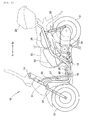
Fig. 1 is a left side view of a saddle-ride-type vehicle according to the invention. -
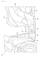
Fig. 2 is a side view of an essential part of the saddle-ride-type vehicle according to the invention. -
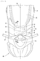
Fig. 3 is a plan view of the essential part of the saddle-ride-type vehicle according to the invention. -
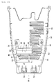
Fig. 4 is a plan view of an essential part showing the inside of a step by removing a lid. -
Fig. 5 is a plan view of the step. -
Fig. 6 is a left side view of the step. -
Fig. 7 is a left side view of an undercover. -
Fig. 8 is a view as viewed in the direction indicated by an arrow 8 inFig. 7 . -
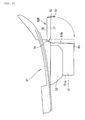
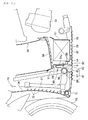
Fig. 9 is a cross-sectional view taken along a line 9-9 inFig. 3 . -
Fig. 10 is a cross-sectional view for explaining a modification. -
Fig. 11 is a left side view of a step according to another modification. -
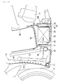
Fig. 12 is a cross-sectional view for explaining still another modification. - An embodiment of the invention is explained by reference to attached drawings. The drawings are viewed in accordance with the direction of symbols. Further, "frontward and rearward directions" (
Fig. 1 , Fr, Rr) and "leftward and rightward directions" are determined with reference to a rider sitting on a seat. - As shown in
Fig. 1 , a saddle-ride-type vehicle 10 is a two-wheeled vehicle which travels using arear wheel 21 as a drive wheel. In the saddle-ride-type vehicle 10, afront fork 12 which incorporates a front cushion therein is steerably supported on ahead pipe 11. Afront wheel 13 is rotatably mounted on a lower portion of thefront fork 12. A steering handle 14 is mounted on an upper portion of thefront fork 12. A downframe 15 is extended from thehead pipe 11. Alower frame 16 is extended rearwardly in the longitudinal direction of the vehicle from a lower end of thedown frame 15. Aseat frame 17 is extended rearwardly in the longitudinal direction of the vehicle from a rear portion of thelower frame 16. Apower unit 19 is extended rearwardly in the longitudinal direction of the vehicle from the rear portion of thelower frame 16 by way of apivot shaft 18. Therear wheel 21 is supported on a rear portion of thepower unit 19. An upper portion of arear cushion 22 which is extended upwardly from the rear portion of thepower unit 19 is connected to theseat frame 17. - The saddle-ride-
type vehicle 10 includes: aseat 23 and arear storage part 24 referred to as a top box which are supported on theseat rail 17; aluggage box 25 and afuel tank 26 which are arranged below theseat 23; aradiator 27 which constitutes a high-temperature member and is arranged between thefront wheel 13 and theseat 23; and ahollow partition wall 60 and abattery 28 constituting an electric component which are arranged behind theradiator 27. - As shown in
Fig. 2 , the saddle-ride-type vehicle 10 further includes a floor-shapedstep 31 which supports feet of the rider in front of and below theseat 23 on which the rider is seated, and an undercover 32 which covers thestep 31 from below. In addition, the saddle-ride-type vehicle 10 includes: left and right under side covers 33 which close a gap formed between thestep 31 and the undercover 32; afront cover 34 which is disposed in front of thestep 31 and behind thefront wheel 13; thebattery 28 which is disposed at a position surrounded by thestep 31, the undercover 32, and the left andright undercovers 33; and arear cover 36 and thepower unit 19 which are disposed behind thestep 31. - As shown in
Fig. 3 , the steering handle 14 andmeters 37 are arranged in front of thestep 31 in the longitudinal direction of the vehicle. Thestep 31 includes alid 38 on a center portion thereof. Thelid 38 can be removed from thestep 31 by looseningscrews lid 38 is formed coplanar with an upper surface of thestep 31. The upper surface of thestep 31 forms a tread surface on which the rider places his feet. - The
power unit 19 which is a heavy object is arranged on a left side in the vehicle width direction with respect to a vehiclebody center line 41, and thebattery 28 is arranged on a right side in the vehicle width direction with respect to the vehiclebody center line 41. Accordingly, the balance is taken between the left side and the right side. - That is, as shown in
Fig. 4 andFig. 5 , in a state where thelid 38 is removed, thebattery 28 which forms an electric component is arranged at a position offset on a right side with respect to the vehicle body center line (center line in the vehicle width direction) 41 (on a side opposite to the power unit 19), andfuse boxes coupler 43, aharness 44 are arranged on a left side with respect to the vehiclebody center line 41. Thebattery 28 is fixed to thestep 31 using a strip-shapedband 45. Asmall sub lid 46 is mounted on thestep 31 on a left side in the vehicle width direction. Thesub lid 46 is a lid which covers a radiator coolingliquid filling port 47 disposed below thesub lid 46. - A distance L exists between the vehicle
body center line 41 and acenter line 48 of thebattery 28. That is, thebattery 28 is arranged in an offset manner on a right side in the vehicle width direction with respect to the vehiclebody center line 41. Thebattery 28 is heavy compared to thefuse box 42 and the like. By arranging the power unit (Fig. 3 , symbol 19) on a side opposite to thebattery 28, the saddle-ride-type vehicle 10 can take the balance in weight in the left and right directions between thepower unit 19 and thebattery 28. - The
fuse boxes coupler 43 are arranged on a left side in the vehicle width direction with respect to the vehiclebody center line 41. Thebattery 28, thefuse boxes coupler 43 and theharness 44 are efficiently housed in the center of thestep 31 whose volume and area are limited. - As shown in
Fig. 7 , thestep 31 includes a battery storing recessedportion 51 and a recessedportion 52 for storing electric articles at the center in the vehicle width direction. - As shown in
Fig. 8 , the battery storing recessedportion 51 largely projects downwardly. The recessedportion 52 for storing electric articles projects downwardly but not as much as the battery storing recessedportion 51. - As shown in
Fig. 9 , the undercover 32 is a resin-molded product having a relatively shallow dish shape. The undercover 32 has ahook 53 on a distal end thereof. The undercover 32 also has a hollowheat shielding wall 60 which projects upwardly on a portion thereof behind thehook 53 in the longitudinal direction of the vehicle. The undercover 32 further includesribs 54 which project upwardly slightly behind the hollowheat shielding wall 60 and are brought into contact with the battery storing recessedportion 51 indicated by an imaginary line. A space is defined between the battery storing recessedportion 51 and the undercover 32 by theribs 54. That is, a gap defined between thestep 31 indicated by an imaginary line and the undercover 32 indicated by a solid line is closed by under side covers (Fig. 2 , symbol 33). - As shown in
Fig. 10 , the undercover 32 includes: hooks 53, 53 on a front portion thereof. The undercover 32 also includes theribs heat shielding wall 60 in front of theright rib 54. The undercover 32 still further includes a large number of dischargeair opening portions 55 in front of the hollowheat shielding wall 60 in the longitudinal direction of the vehicle and on a left side of the hollowheat shielding wall 60. - Although explained in detail by reference to
Fig. 9 , the hollowheat shielding wall 60 is a box-shaped body or a cylindrical body constituted of a plurality of wall portions and has sufficient rigidity. The hollowheat shielding wall 60 is formed along the dischargeair opening portions 55 and hence, the rigidity of the undercover 32 can be maintained although the dischargeair opening portions 55 are formed. - As shown in
Fig. 11 , a front portion of the undercover 32 is supported by hooking thehook 53 on the frontlower cross frame 71. - The
step 31 includes the battery storing recessedportion 51 and theremovable lid 38. Thebattery 28 stored in the battery storing recessedportion 51 can be inspected by opening thelid 38. That is, thebattery 28 is arranged between a tread surface of the step 31 (the surface at the same level as an upper surface of the lid 38) and the undercover 32. - Further, the undercover 32 includes the hollow
heat shielding wall 60 as an integral part thereof. The hollowheat shielding wall 60 includes, at least, afront wall portion 61 and arear wall portion 62 which is formed in a spaced-apart manner from thefront wall portion 61. The hollowheat shielding wall 60, more preferably, includes: left and rightside wall portions 63 which respectively connect left and right end portions of thefront wall portion 61 and left and right end portions of therear wall portion 62 to each other; and aceiling 64. The hollowheat shielding wall 60 is still more preferably formed such that thefront wall portion 61 is formed into a stepped shape. That is, thefront wall portion 61 is formed into a stepped wall which is constituted of: ahorizontal portion 65 which corresponds to a tread surface of a step; anupper wall portion 66 which is raised from thehorizontal portion 65; and alower wall portion 67 which extends downwardly from thehorizontal portion 65. Due to a space S defined by thefront wall portion 61, therear wall portion 62, the left and rightside wall portions 63 and theceiling wall 64, a heat shielding effect can be increased. - The stepped wall can increase rigidity compared to a flat wall and hence, the stepped wall can contribute to the increase of rigidity of the
whole undercover 32. Thefront wall portion 61 has the stepped shape and hence, thefront wall portion 61 can be arranged close to thecross member 68. Thehorizontal portion 65 of the stepped wall is formed along the curve of a pipe of thecross member 68 and hence, the frame can be used also as a rigid member for the cover. - Further, it is possible to secure a space which forms an air layer (a gap 69) between the
front wall portion 61 and therear wall portion 62. - The hollow
heat shielding wall 60 having the above-mentioned structure is arranged such that the hollowheat shielding wall 60 projects upwardly between theradiator 27 disposed right behind thefront wheel 13 and thebattery 28. A plurality of air introducing openingportions 72 which introduce traveling air are formed in thefront cover 34 arranged in front of theradiator 27 in the longitudinal direction of the vehicle in a state where the plurality of air introducing openingportions 72 are arranged in the vertical direction. Traveling air which passes through the air introducing openingportions 72 cools theradiator 27, while the traveling air per se is heated and becomes discharge air. The discharge air flows toward a rear side of the vehicle, and is discharged mainly from the dischargeair opening portions 55. - During such an operation, the
radiator 27 is at a higher temperature than thebattery 28 and hence, heat which theradiator 27 generates moves toward thebattery 28. An air layer (space S) exists between thefront wall portion 61 and therear wall portion 62, and this air layer exhibits the favorable heat shielding performance. Further, in this embodiment, thefront wall portion 61, therear wall portion 62 and thefront wall 51a of the battery storing recessedportion 51 form a heat shielding wall and exhibit a favorable heat shielding action. As a result, the increase of a temperature of thebattery 28 can be suppressed. - It is sufficient that a width of the hollow
heat shielding wall 60 in the vehicle width direction (Fig. 8 , symbol L2) is equal to a width of thebattery 28 in the vehicle width direction. As a result, the increase of a weight and the large-sizing of the undercover 32 can be prevented. In case that the undercover 32 is a resin molded product, a resin material can be saved. - Although the
ceiling 64 of the hollowheat shielding wall 60 may be omitted, it is preferable to provide theceiling 64. By providing theceiling 64, there is no possibility that heated air is leaked upwardly. Since there is no movement of air (the movement of air being small even when air moves), the convective heat transfer can be suppressed so that the heat shielding performance can be increased. Additionally, since heat is shielded by theceiling 64, there is no possibility that flying pebbles or mud water enters the inside of the undercover 32 thorough the hollowheat shielding wall 60. - As shown in
Fig. 12 , a rear hollowheat shielding wall 60F may be provided behind thebattery 28. Due to the provision of the rear hollowheat shielding wall 60F, it is possible to shield heat which is directed toward thebattery 28 from thevehicle drive source 73. - It is also possible to provide the hollow
heat shielding wall 60 in front of thebattery 28 and the rear hollowheat shielding wall 60F behind thebattery 28 respectively. - In the explanation made heretofore, the hollow
heat shielding walls heat shielding walls portion 51. A specific example of this case is explained hereinafter. - As shown in
Fig. 4 , the battery storing recessedportion 51 is integrally formed with thestep 31, and the rear hollowheat shielding wall 60F is connected to at least one of thefront wall 51a and arear wall 51b (in this embodiment, therear wall 51b) which forms the battery storing recessedportion 51 by way of a bendablemovable portion 75. The rear hollowheat shielding wall 60F is formed simultaneously with thestep 31 by a resin injection molding method. - As shown in
Fig. 3 , the rear hollowheat shielding wall 60F is constituted of a spaced-apartwall 76, aperipheral wall 77 which is raised from the spaced-apartwall 76, and atongue member 78 which is formed on a portion of the rear hollowheat shielding wall 60F remotest from themovable portion 75. Ahole 79 having an approximately 5mm is formed in thetongue member 78. Aprojection 81 which projects downwardly from the spaced-apart wall of the battery storing recessedportion 51 is fitted in thehole 79. - As shown in
Fig. 4 , themovable portion 75 is formed as a fragile portion having a thickness smaller than a thicknesses of other portions so that themovable portion 75 can be easily bent. Accordingly, by bending themovable portion 75 by an approximately 90°, as indicated by an imaginary line, an open end of theperipheral wall 77 is brought into contact with therear wall 51b. Thetongue member 78 is engaged with theprojection 81. It is sufficient that themovable portion 75 is formed of a hinge and hence, another hinge structure may be adopted as themovable portion 75 besides the case where themovable portion 75 is formed of the small wall thickness member. - As shown in
Fig. 4 , the rear hollowheat shielding wall 60F is interposed between thebattery 28 and thevehicle drive source 73. With respect to the rear hollowheat shielding wall 60F, the spaced-apartwall 76 is arranged parallel to therear wall 51b, and air existing between the spaced-apartwall 76 and therear wall 51b is substantially sealed by theperipheral wall 77. The flow of air is suppressed and hence, the heat insulation performance can be increased. - In this embodiment, the rear hollow
heat shielding wall 60F is connected to therear wall 51b by way of themovable portion 75. However, themovable portion 75 may be omitted. That is, a pentahedron rear hollowheat shielding wall 60F which is formed of the spaced-apartwall 76 and theperipheral wall 77 may be prepared as a separate part, and the separate part may be fixed to therear wall 51b using an adhesive agent or screws. - From a viewpoint of forming an air layer having a fixed thickness, the rear hollow
heat shielding wall 60F may be formed of only the spaced-apartwall 76 which is spaced apart from therear wall 51b while omitting theperipheral wall 77. However, by forming rear hollowheat shielding wall 60F by also using theperipheral wall 77, the flow-in and the flow-out of air can be suppressed so that a heat insulation action can be increased. - Further, the hollow
heat shielding wall 60 may be also attached to thefront wall 51a. As a result of attaching the hollowheat shielding wall 60 in this manner, the undercover 32 becomes substantially flat. By forming the undercover 32 into a flat shape, traveling air is minimally entangled and hence, the undercover 32 having a flat shape is preferable from this point. - The electric components indicate electric or electronic components in general which are relatively easily affected by heat such as a circuit board having an electronic circuit and the like besides the
battery 28 and thefuse box 26 exemplified in the embodiment. - Further, as the
vehicle drive source 73, any kind of vehicle drive sources may be used provided that the vehicle drive source is a drive source which generates a drive force for making a vehicle travel such as a gasoline engine, an electric motor, or a hydraulic motor. The drive source generates heat and hence, the drive source corresponds to a high-temperature component. - Further, although the hollow
heat shielding walls heat shielding walls heat shielding walls - Further, in the embodiment, the battery storing recessed
portion 51 is formed on thestep 31. However, by providing the structure where thebattery 28 is arranged between thestep 31 and the undercover 32 in a state where thebattery 28 is supported on a bracket which extends from the vehicle body frame, it is possible to prevent the weight of thebattery 28 from being applied to thestep 31. - The invention is applicable to a saddle-ride-type vehicle where a floor-shaped step is disposed in front of a seat.
-
- 10:
- saddle-ride-type vehicle
- 13:
- front wheel
- 19:
- power unit
- 23:
- seat
- 27:
- high temperature component (radiator)
- 28:
- electric component (battery)
- 31:
- step
- 32:
- undercover
- 38:
- lid
- 41:
- vehicle body center line
- 48:
- center line of battery
- 51:
- battery storing recessed portion
- 51a:
- front wall of battery storing recessed portion
- 51b:
- rear wall of battery storing recessed portion
- 55:
- discharge air opening portion
- 60, 60F:
- hollow heat shielding wall
- 61:
- front wall portion
- 62:
- rear wall portion
- 63:
- left wall portion, right wall portion
- 64:
- ceiling
- 73:
- high temperature component (vehicle drive source)
- 75:
- movable portion
- 76:
- spaced-apart wall
- 77:
- peripheral wall
- L:
- offset amount (distance)
Claims (9)
- A saddle-ride-type vehicle (10) provided with a seat (23) on which a rider is seated, a floor-shaped step (31) which supports legs of the rider, and an undercover (32) which covers the step (31) from below, wherein
an electric component (28) is arranged below a tread surface of the step (31) and above the undercover (32), a high-temperature component (27, 73) having a higher temperature than the electric component (28) is arranged at a position above the undercover (32), and
a hollow heat shielding wall (60, 60F) having a front wall portion (61) and a rear wall portion (62) formed behind the front wall portion (61) in a spaced-apart manner is formed on the undercover (32) in an upwardly projecting manner. - The saddle-ride-type vehicle according to claim 1, wherein the hollow heat shielding wall (60, 60F) includes left and right side wall portions (63) which respectively connect left and right end portions of the front wall portion (61) and left and right end portions of the rear wall portion (62) to each other, and a ceiling (64) which connects an upper end of the front wall portion (61), an upper end of the rear wall portion (62) and upper ends of the left and right side wall portions (63) to each other.
- The saddle-ride-type vehicle according to claim 1 or claim 2, wherein the high-temperature component (27) is a radiator (27) arranged between a front wheel (13) and the electric component (28), a discharge air opening portion (55) which guides discharged air from the radiator (27) is formed in the undercover (32), and at least a portion of the hollow heat shielding wall (60, 60F) is arranged adjacent to the discharge air opening portion (55).
- The saddle-ride-type vehicle according to any one of claims 1 to 3, wherein the saddle-ride-type vehicle includes a power unit (19) which is swingably supported at one side of a vehicle body center line (41), and
the electric component (28) is a battery (28), the battery (28) is arranged in an offset manner toward the other side with respect to the vehicle body center line (41), and the hollow heat shielding wall (60) is disposed only in front of the battery (28) in the longitudinal direction of the vehicle. - The saddle-ride-type vehicle according to claim 4, wherein the step (31) includes a battery storing recessed portion (51) which opens upwardly and stores the battery (28) therein, and a lid (38) which closes the battery storing recessed portion (51).
- The saddle-ride-type vehicle according to any one of claims 1 to 5, wherein at least one of the front wall portion (61) and the rear wall portion (63) is a stepped wall.
- The saddle-ride-type vehicle according to claim 1 or claim 2, wherein the high-temperature component (73) is a vehicle drive source (73) arranged behind the electric component (28) in the longitudinal direction of the vehicle.
- A saddle-ride-type vehicle provided with a seat (23) on which a rider is seated, a step (31) which
supports legs of the rider, and an undercover (32) which covers the step (31) from below, wherein
a battery (28) is arranged below a tread surface of the step (31) and above the undercover (32), a high-temperature component (27, 73) having a higher temperature than the battery (28) is arranged at a position above the undercover (32),
the step (31) includes a battery storing recessed portion (51) which opens upwardly and stores the battery (28) therein, and a spaced-apart wall (76) which is spaced apart from at least one of a front wall (51a) and a rear wall (51b) which form the battery storing recessed portion (51), and a hollow heat shielding wall (60, 60F) which forms an air layer between the hollow heat shielding wall (60, 60F) and the front wall (51a) or the rear wall (51b) is provided. - The saddle-ride-type vehicle according to claim 8, wherein the spaced-apart wall (76) is connected to the step (31) by way of a bendable movable portion (75), and
the hollow heat shielding wall (60, 60F) is configured such that an open end of a peripheral wall (77) formed on an outer periphery of the spaced-apart wall (76) is brought into contact with the front wall (51a) or the rear wall (51b).
Applications Claiming Priority (2)
| Application Number | Priority Date | Filing Date | Title |
|---|---|---|---|
| JP2014056326 | 2014-03-19 | ||
| JP2014208421A JP6329476B2 (en) | 2014-03-19 | 2014-10-09 | Saddle riding |
Publications (2)
| Publication Number | Publication Date |
|---|---|
| EP2921385A1 true EP2921385A1 (en) | 2015-09-23 |
| EP2921385B1 EP2921385B1 (en) | 2019-10-30 |
Family
ID=52589286
Family Applications (1)
| Application Number | Title | Priority Date | Filing Date |
|---|---|---|---|
| EP15156863.1A Active EP2921385B1 (en) | 2014-03-19 | 2015-02-27 | Saddle-ride-type vehicle |
Country Status (2)
| Country | Link |
|---|---|
| EP (1) | EP2921385B1 (en) |
| JP (1) | JP6329476B2 (en) |
Cited By (1)
| Publication number | Priority date | Publication date | Assignee | Title |
|---|---|---|---|---|
| WO2017171661A1 (en) * | 2016-03-29 | 2017-10-05 | Honda Motor Company Limited | Undercover structure for motorcycle |
Families Citing this family (3)
| Publication number | Priority date | Publication date | Assignee | Title |
|---|---|---|---|---|
| JP6559356B2 (en) | 2016-08-08 | 2019-08-14 | 本田技研工業株式会社 | vehicle |
| JP7431948B2 (en) * | 2020-03-31 | 2024-02-15 | 本田技研工業株式会社 | Radiator exhaust structure for saddle-type vehicles |
| JP7625021B2 (en) * | 2023-01-18 | 2025-01-31 | 本田技研工業株式会社 | Saddle-type vehicle |
Citations (8)
| Publication number | Priority date | Publication date | Assignee | Title |
|---|---|---|---|---|
| JP2000313388A (en) * | 1999-04-28 | 2000-11-14 | Honda Motor Co Ltd | Scooter type vehicle |
| JP2001310784A (en) * | 2000-04-26 | 2001-11-06 | Honda Motor Co Ltd | Scooter type vehicle |
| EP1243500A2 (en) * | 2001-03-23 | 2002-09-25 | Honda Giken Kogyo Kabushiki Kaisha | Hinged lid structure for vehicles |
| EP1496241A2 (en) * | 2003-07-07 | 2005-01-12 | Yamaha Hatsudoki Kabushiki Kaisha | Motorcycle having a wind guide structure |
| EP1847451A1 (en) * | 2006-04-19 | 2007-10-24 | HONDA MOTOR CO., Ltd. | Motorcycle |
| EP1864900A1 (en) * | 2006-06-09 | 2007-12-12 | Yamaha Hatsudoki Kabushiki Kaisha | Motorcycle |
| JP2013193641A (en) | 2012-03-22 | 2013-09-30 | Honda Motor Co Ltd | Air-exhaust structure for radiator of saddle riding-type vehicle |
| EP2703272A1 (en) * | 2012-08-28 | 2014-03-05 | Honda Motor Co., Ltd. | Storage part structure for saddle type vehicle |
Family Cites Families (2)
| Publication number | Priority date | Publication date | Assignee | Title |
|---|---|---|---|---|
| JPS57122491U (en) * | 1981-01-26 | 1982-07-30 | ||
| JP5225913B2 (en) * | 2009-03-27 | 2013-07-03 | 本田技研工業株式会社 | Electric vehicle |
-
2014
- 2014-10-09 JP JP2014208421A patent/JP6329476B2/en not_active Expired - Fee Related
-
2015
- 2015-02-27 EP EP15156863.1A patent/EP2921385B1/en active Active
Patent Citations (8)
| Publication number | Priority date | Publication date | Assignee | Title |
|---|---|---|---|---|
| JP2000313388A (en) * | 1999-04-28 | 2000-11-14 | Honda Motor Co Ltd | Scooter type vehicle |
| JP2001310784A (en) * | 2000-04-26 | 2001-11-06 | Honda Motor Co Ltd | Scooter type vehicle |
| EP1243500A2 (en) * | 2001-03-23 | 2002-09-25 | Honda Giken Kogyo Kabushiki Kaisha | Hinged lid structure for vehicles |
| EP1496241A2 (en) * | 2003-07-07 | 2005-01-12 | Yamaha Hatsudoki Kabushiki Kaisha | Motorcycle having a wind guide structure |
| EP1847451A1 (en) * | 2006-04-19 | 2007-10-24 | HONDA MOTOR CO., Ltd. | Motorcycle |
| EP1864900A1 (en) * | 2006-06-09 | 2007-12-12 | Yamaha Hatsudoki Kabushiki Kaisha | Motorcycle |
| JP2013193641A (en) | 2012-03-22 | 2013-09-30 | Honda Motor Co Ltd | Air-exhaust structure for radiator of saddle riding-type vehicle |
| EP2703272A1 (en) * | 2012-08-28 | 2014-03-05 | Honda Motor Co., Ltd. | Storage part structure for saddle type vehicle |
Cited By (3)
| Publication number | Priority date | Publication date | Assignee | Title |
|---|---|---|---|---|
| WO2017171661A1 (en) * | 2016-03-29 | 2017-10-05 | Honda Motor Company Limited | Undercover structure for motorcycle |
| CN108698665A (en) * | 2016-03-29 | 2018-10-23 | 本田技研工业株式会社 | The bottom cover structure of motorcycle |
| CN108698665B (en) * | 2016-03-29 | 2020-02-14 | 本田技研工业株式会社 | Bottom cover structure of motorcycle |
Also Published As
| Publication number | Publication date |
|---|---|
| JP6329476B2 (en) | 2018-05-23 |
| JP2015193364A (en) | 2015-11-05 |
| EP2921385B1 (en) | 2019-10-30 |
Similar Documents
| Publication | Publication Date | Title |
|---|---|---|
| CN109484547B (en) | ride-on vehicle | |
| US8474895B2 (en) | Inner rack structure for saddle-ride type vehicle | |
| JP5640382B2 (en) | Vehicle battery assembly cooling structure and battery assembly with water jacket | |
| EP2921385B1 (en) | Saddle-ride-type vehicle | |
| EP2669502B1 (en) | Saddle-ride-type vehicle | |
| EP3219596B1 (en) | Abs modulator support structure of saddle type vehicle | |
| JP5852072B2 (en) | Saddle riding | |
| CN102849155B (en) | Waterproof structure of vehicle | |
| US8776923B2 (en) | Air guide structure for saddle type vehicle | |
| EP3061679B1 (en) | Rear structure for saddle-ride type vehicle | |
| JP5926652B2 (en) | Storage structure for saddle-ride type vehicles | |
| CN105416450A (en) | The front structure of the saddle-riding vehicle | |
| JP2013032050A (en) | Vehicle with step floor | |
| JP5815049B2 (en) | Saddle riding vehicle | |
| TW523476B (en) | Fuel device for scooter type vehicle | |
| WO2015152841A1 (en) | Reserve tank mounting structure for a scooter | |
| JP5863630B2 (en) | In-vehicle electrical component layout | |
| JP3849738B2 (en) | Scooter type motorcycle | |
| JP5012488B2 (en) | Automotive fuel tank arrangement structure | |
| JP5960432B2 (en) | Rear fender structure for two-wheeled vehicles | |
| JP7657250B2 (en) | Front body structure of saddle-type vehicle | |
| JP5712091B2 (en) | Motorcycle | |
| JP4296438B2 (en) | Scooter type motorcycle | |
| JP6086609B2 (en) | vehicle | |
| TH72184A (en) | Storage box structure and fuel tank on the motorcycle |
Legal Events
| Date | Code | Title | Description |
|---|---|---|---|
| PUAI | Public reference made under article 153(3) epc to a published international application that has entered the european phase |
Free format text: ORIGINAL CODE: 0009012 |
|
| 17P | Request for examination filed |
Effective date: 20150227 |
|
| AK | Designated contracting states |
Kind code of ref document: A1 Designated state(s): AL AT BE BG CH CY CZ DE DK EE ES FI FR GB GR HR HU IE IS IT LI LT LU LV MC MK MT NL NO PL PT RO RS SE SI SK SM TR |
|
| AX | Request for extension of the european patent |
Extension state: BA ME |
|
| 17Q | First examination report despatched |
Effective date: 20160411 |
|
| STAA | Information on the status of an ep patent application or granted ep patent |
Free format text: STATUS: EXAMINATION IS IN PROGRESS |
|
| GRAP | Despatch of communication of intention to grant a patent |
Free format text: ORIGINAL CODE: EPIDOSNIGR1 |
|
| STAA | Information on the status of an ep patent application or granted ep patent |
Free format text: STATUS: GRANT OF PATENT IS INTENDED |
|
| INTG | Intention to grant announced |
Effective date: 20190508 |
|
| GRAJ | Information related to disapproval of communication of intention to grant by the applicant or resumption of examination proceedings by the epo deleted |
Free format text: ORIGINAL CODE: EPIDOSDIGR1 |
|
| STAA | Information on the status of an ep patent application or granted ep patent |
Free format text: STATUS: EXAMINATION IS IN PROGRESS |
|
| GRAR | Information related to intention to grant a patent recorded |
Free format text: ORIGINAL CODE: EPIDOSNIGR71 |
|
| GRAS | Grant fee paid |
Free format text: ORIGINAL CODE: EPIDOSNIGR3 |
|
| STAA | Information on the status of an ep patent application or granted ep patent |
Free format text: STATUS: GRANT OF PATENT IS INTENDED |
|
| GRAA | (expected) grant |
Free format text: ORIGINAL CODE: 0009210 |
|
| STAA | Information on the status of an ep patent application or granted ep patent |
Free format text: STATUS: THE PATENT HAS BEEN GRANTED |
|
| INTC | Intention to grant announced (deleted) | ||
| AK | Designated contracting states |
Kind code of ref document: B1 Designated state(s): AL AT BE BG CH CY CZ DE DK EE ES FI FR GB GR HR HU IE IS IT LI LT LU LV MC MK MT NL NO PL PT RO RS SE SI SK SM TR |
|
| INTG | Intention to grant announced |
Effective date: 20190920 |
|
| REG | Reference to a national code |
Ref country code: GB Ref legal event code: FG4D |
|
| REG | Reference to a national code |
Ref country code: CH Ref legal event code: EP |
|
| REG | Reference to a national code |
Ref country code: AT Ref legal event code: REF Ref document number: 1195849 Country of ref document: AT Kind code of ref document: T Effective date: 20191115 |
|
| REG | Reference to a national code |
Ref country code: DE Ref legal event code: R096 Ref document number: 602015040570 Country of ref document: DE |
|
| REG | Reference to a national code |
Ref country code: IE Ref legal event code: FG4D |
|
| REG | Reference to a national code |
Ref country code: LT Ref legal event code: MG4D |
|
| PG25 | Lapsed in a contracting state [announced via postgrant information from national office to epo] |
Ref country code: NL Free format text: LAPSE BECAUSE OF FAILURE TO SUBMIT A TRANSLATION OF THE DESCRIPTION OR TO PAY THE FEE WITHIN THE PRESCRIBED TIME-LIMIT Effective date: 20191030 Ref country code: PL Free format text: LAPSE BECAUSE OF FAILURE TO SUBMIT A TRANSLATION OF THE DESCRIPTION OR TO PAY THE FEE WITHIN THE PRESCRIBED TIME-LIMIT Effective date: 20191030 Ref country code: LV Free format text: LAPSE BECAUSE OF FAILURE TO SUBMIT A TRANSLATION OF THE DESCRIPTION OR TO PAY THE FEE WITHIN THE PRESCRIBED TIME-LIMIT Effective date: 20191030 Ref country code: NO Free format text: LAPSE BECAUSE OF FAILURE TO SUBMIT A TRANSLATION OF THE DESCRIPTION OR TO PAY THE FEE WITHIN THE PRESCRIBED TIME-LIMIT Effective date: 20200130 Ref country code: SE Free format text: LAPSE BECAUSE OF FAILURE TO SUBMIT A TRANSLATION OF THE DESCRIPTION OR TO PAY THE FEE WITHIN THE PRESCRIBED TIME-LIMIT Effective date: 20191030 Ref country code: FI Free format text: LAPSE BECAUSE OF FAILURE TO SUBMIT A TRANSLATION OF THE DESCRIPTION OR TO PAY THE FEE WITHIN THE PRESCRIBED TIME-LIMIT Effective date: 20191030 Ref country code: BG Free format text: LAPSE BECAUSE OF FAILURE TO SUBMIT A TRANSLATION OF THE DESCRIPTION OR TO PAY THE FEE WITHIN THE PRESCRIBED TIME-LIMIT Effective date: 20200130 Ref country code: PT Free format text: LAPSE BECAUSE OF FAILURE TO SUBMIT A TRANSLATION OF THE DESCRIPTION OR TO PAY THE FEE WITHIN THE PRESCRIBED TIME-LIMIT Effective date: 20200302 Ref country code: ES Free format text: LAPSE BECAUSE OF FAILURE TO SUBMIT A TRANSLATION OF THE DESCRIPTION OR TO PAY THE FEE WITHIN THE PRESCRIBED TIME-LIMIT Effective date: 20191030 Ref country code: GR Free format text: LAPSE BECAUSE OF FAILURE TO SUBMIT A TRANSLATION OF THE DESCRIPTION OR TO PAY THE FEE WITHIN THE PRESCRIBED TIME-LIMIT Effective date: 20200131 Ref country code: LT Free format text: LAPSE BECAUSE OF FAILURE TO SUBMIT A TRANSLATION OF THE DESCRIPTION OR TO PAY THE FEE WITHIN THE PRESCRIBED TIME-LIMIT Effective date: 20191030 |
|
| REG | Reference to a national code |
Ref country code: NL Ref legal event code: MP Effective date: 20191030 |
|
| PG25 | Lapsed in a contracting state [announced via postgrant information from national office to epo] |
Ref country code: IS Free format text: LAPSE BECAUSE OF FAILURE TO SUBMIT A TRANSLATION OF THE DESCRIPTION OR TO PAY THE FEE WITHIN THE PRESCRIBED TIME-LIMIT Effective date: 20200229 Ref country code: HR Free format text: LAPSE BECAUSE OF FAILURE TO SUBMIT A TRANSLATION OF THE DESCRIPTION OR TO PAY THE FEE WITHIN THE PRESCRIBED TIME-LIMIT Effective date: 20191030 Ref country code: RS Free format text: LAPSE BECAUSE OF FAILURE TO SUBMIT A TRANSLATION OF THE DESCRIPTION OR TO PAY THE FEE WITHIN THE PRESCRIBED TIME-LIMIT Effective date: 20191030 |
|
| PG25 | Lapsed in a contracting state [announced via postgrant information from national office to epo] |
Ref country code: AL Free format text: LAPSE BECAUSE OF FAILURE TO SUBMIT A TRANSLATION OF THE DESCRIPTION OR TO PAY THE FEE WITHIN THE PRESCRIBED TIME-LIMIT Effective date: 20191030 |
|
| PG25 | Lapsed in a contracting state [announced via postgrant information from national office to epo] |
Ref country code: CZ Free format text: LAPSE BECAUSE OF FAILURE TO SUBMIT A TRANSLATION OF THE DESCRIPTION OR TO PAY THE FEE WITHIN THE PRESCRIBED TIME-LIMIT Effective date: 20191030 Ref country code: RO Free format text: LAPSE BECAUSE OF FAILURE TO SUBMIT A TRANSLATION OF THE DESCRIPTION OR TO PAY THE FEE WITHIN THE PRESCRIBED TIME-LIMIT Effective date: 20191030 Ref country code: EE Free format text: LAPSE BECAUSE OF FAILURE TO SUBMIT A TRANSLATION OF THE DESCRIPTION OR TO PAY THE FEE WITHIN THE PRESCRIBED TIME-LIMIT Effective date: 20191030 Ref country code: DK Free format text: LAPSE BECAUSE OF FAILURE TO SUBMIT A TRANSLATION OF THE DESCRIPTION OR TO PAY THE FEE WITHIN THE PRESCRIBED TIME-LIMIT Effective date: 20191030 |
|
| REG | Reference to a national code |
Ref country code: DE Ref legal event code: R097 Ref document number: 602015040570 Country of ref document: DE |
|
| REG | Reference to a national code |
Ref country code: AT Ref legal event code: MK05 Ref document number: 1195849 Country of ref document: AT Kind code of ref document: T Effective date: 20191030 |
|
| PG25 | Lapsed in a contracting state [announced via postgrant information from national office to epo] |
Ref country code: SM Free format text: LAPSE BECAUSE OF FAILURE TO SUBMIT A TRANSLATION OF THE DESCRIPTION OR TO PAY THE FEE WITHIN THE PRESCRIBED TIME-LIMIT Effective date: 20191030 Ref country code: SK Free format text: LAPSE BECAUSE OF FAILURE TO SUBMIT A TRANSLATION OF THE DESCRIPTION OR TO PAY THE FEE WITHIN THE PRESCRIBED TIME-LIMIT Effective date: 20191030 |
|
| REG | Reference to a national code |
Ref country code: DE Ref legal event code: R119 Ref document number: 602015040570 Country of ref document: DE |
|
| PLBE | No opposition filed within time limit |
Free format text: ORIGINAL CODE: 0009261 |
|
| STAA | Information on the status of an ep patent application or granted ep patent |
Free format text: STATUS: NO OPPOSITION FILED WITHIN TIME LIMIT |
|
| REG | Reference to a national code |
Ref country code: CH Ref legal event code: PL |
|
| 26N | No opposition filed |
Effective date: 20200731 |
|
| GBPC | Gb: european patent ceased through non-payment of renewal fee |
Effective date: 20200227 |
|
| REG | Reference to a national code |
Ref country code: BE Ref legal event code: MM Effective date: 20200229 |
|
| PG25 | Lapsed in a contracting state [announced via postgrant information from national office to epo] |
Ref country code: LU Free format text: LAPSE BECAUSE OF NON-PAYMENT OF DUE FEES Effective date: 20200227 Ref country code: MC Free format text: LAPSE BECAUSE OF FAILURE TO SUBMIT A TRANSLATION OF THE DESCRIPTION OR TO PAY THE FEE WITHIN THE PRESCRIBED TIME-LIMIT Effective date: 20191030 |
|
| PG25 | Lapsed in a contracting state [announced via postgrant information from national office to epo] |
Ref country code: LI Free format text: LAPSE BECAUSE OF NON-PAYMENT OF DUE FEES Effective date: 20200229 Ref country code: AT Free format text: LAPSE BECAUSE OF FAILURE TO SUBMIT A TRANSLATION OF THE DESCRIPTION OR TO PAY THE FEE WITHIN THE PRESCRIBED TIME-LIMIT Effective date: 20191030 Ref country code: CH Free format text: LAPSE BECAUSE OF NON-PAYMENT OF DUE FEES Effective date: 20200229 Ref country code: SI Free format text: LAPSE BECAUSE OF FAILURE TO SUBMIT A TRANSLATION OF THE DESCRIPTION OR TO PAY THE FEE WITHIN THE PRESCRIBED TIME-LIMIT Effective date: 20191030 |
|
| PG25 | Lapsed in a contracting state [announced via postgrant information from national office to epo] |
Ref country code: FR Free format text: LAPSE BECAUSE OF NON-PAYMENT OF DUE FEES Effective date: 20200229 Ref country code: IE Free format text: LAPSE BECAUSE OF NON-PAYMENT OF DUE FEES Effective date: 20200227 Ref country code: DE Free format text: LAPSE BECAUSE OF NON-PAYMENT OF DUE FEES Effective date: 20200901 Ref country code: GB Free format text: LAPSE BECAUSE OF NON-PAYMENT OF DUE FEES Effective date: 20200227 |
|
| PG25 | Lapsed in a contracting state [announced via postgrant information from national office to epo] |
Ref country code: BE Free format text: LAPSE BECAUSE OF NON-PAYMENT OF DUE FEES Effective date: 20200229 |
|
| PG25 | Lapsed in a contracting state [announced via postgrant information from national office to epo] |
Ref country code: TR Free format text: LAPSE BECAUSE OF FAILURE TO SUBMIT A TRANSLATION OF THE DESCRIPTION OR TO PAY THE FEE WITHIN THE PRESCRIBED TIME-LIMIT Effective date: 20191030 Ref country code: MT Free format text: LAPSE BECAUSE OF FAILURE TO SUBMIT A TRANSLATION OF THE DESCRIPTION OR TO PAY THE FEE WITHIN THE PRESCRIBED TIME-LIMIT Effective date: 20191030 Ref country code: CY Free format text: LAPSE BECAUSE OF FAILURE TO SUBMIT A TRANSLATION OF THE DESCRIPTION OR TO PAY THE FEE WITHIN THE PRESCRIBED TIME-LIMIT Effective date: 20191030 |
|
| PG25 | Lapsed in a contracting state [announced via postgrant information from national office to epo] |
Ref country code: MK Free format text: LAPSE BECAUSE OF FAILURE TO SUBMIT A TRANSLATION OF THE DESCRIPTION OR TO PAY THE FEE WITHIN THE PRESCRIBED TIME-LIMIT Effective date: 20191030 |
|
| PGFP | Annual fee paid to national office [announced via postgrant information from national office to epo] |
Ref country code: IT Payment date: 20260121 Year of fee payment: 12 |