EP2921190B1 - Liquid delivering pump - Google Patents
Liquid delivering pump Download PDFInfo
- Publication number
- EP2921190B1 EP2921190B1 EP15159131.0A EP15159131A EP2921190B1 EP 2921190 B1 EP2921190 B1 EP 2921190B1 EP 15159131 A EP15159131 A EP 15159131A EP 2921190 B1 EP2921190 B1 EP 2921190B1
- Authority
- EP
- European Patent Office
- Prior art keywords
- drug
- information
- pump
- display unit
- drug library
- Prior art date
- Legal status (The legal status is an assumption and is not a legal conclusion. Google has not performed a legal analysis and makes no representation as to the accuracy of the status listed.)
- Active
Links
- 239000007788 liquid Substances 0.000 title claims description 75
- 229940079593 drug Drugs 0.000 claims description 267
- 239000003814 drug Substances 0.000 claims description 267
- 238000007689 inspection Methods 0.000 claims description 29
- 238000003825 pressing Methods 0.000 claims description 7
- 230000035939 shock Effects 0.000 description 27
- 238000000034 method Methods 0.000 description 16
- 230000001133 acceleration Effects 0.000 description 15
- 230000004308 accommodation Effects 0.000 description 11
- 230000004048 modification Effects 0.000 description 9
- 238000012986 modification Methods 0.000 description 9
- 238000004891 communication Methods 0.000 description 7
- 238000001802 infusion Methods 0.000 description 7
- 238000001514 detection method Methods 0.000 description 6
- 230000006870 function Effects 0.000 description 6
- 238000012546 transfer Methods 0.000 description 6
- 239000003086 colorant Substances 0.000 description 5
- 230000004044 response Effects 0.000 description 4
- 238000010586 diagram Methods 0.000 description 3
- 230000008569 process Effects 0.000 description 3
- 230000007704 transition Effects 0.000 description 3
- 230000005856 abnormality Effects 0.000 description 2
- 230000003247 decreasing effect Effects 0.000 description 2
- 230000000694 effects Effects 0.000 description 2
- 239000002869 intravenous anesthetic agent Substances 0.000 description 2
- 238000002360 preparation method Methods 0.000 description 2
- HBBGRARXTFLTSG-UHFFFAOYSA-N Lithium ion Chemical compound [Li+] HBBGRARXTFLTSG-UHFFFAOYSA-N 0.000 description 1
- ZTVQQQVZCWLTDF-UHFFFAOYSA-N Remifentanil Chemical compound C1CN(CCC(=O)OC)CCC1(C(=O)OC)N(C(=O)CC)C1=CC=CC=C1 ZTVQQQVZCWLTDF-UHFFFAOYSA-N 0.000 description 1
- 230000003213 activating effect Effects 0.000 description 1
- 229940035674 anesthetics Drugs 0.000 description 1
- 230000002421 anti-septic effect Effects 0.000 description 1
- 239000002246 antineoplastic agent Substances 0.000 description 1
- 229940041181 antineoplastic drug Drugs 0.000 description 1
- 239000008280 blood Substances 0.000 description 1
- 210000004369 blood Anatomy 0.000 description 1
- 230000015556 catabolic process Effects 0.000 description 1
- -1 chemotherapeutics Substances 0.000 description 1
- 239000003193 general anesthetic agent Substances 0.000 description 1
- 230000036541 health Effects 0.000 description 1
- 230000006872 improvement Effects 0.000 description 1
- 239000004973 liquid crystal related substance Substances 0.000 description 1
- 229910001416 lithium ion Inorganic materials 0.000 description 1
- 230000007257 malfunction Effects 0.000 description 1
- 238000007726 management method Methods 0.000 description 1
- 239000000463 material Substances 0.000 description 1
- 229960003793 midazolam Drugs 0.000 description 1
- DDLIGBOFAVUZHB-UHFFFAOYSA-N midazolam Chemical compound C12=CC(Cl)=CC=C2N2C(C)=NC=C2CN=C1C1=CC=CC=C1F DDLIGBOFAVUZHB-UHFFFAOYSA-N 0.000 description 1
- 238000000465 moulding Methods 0.000 description 1
- 235000015097 nutrients Nutrition 0.000 description 1
- 230000000149 penetrating effect Effects 0.000 description 1
- 230000000737 periodic effect Effects 0.000 description 1
- 229960004134 propofol Drugs 0.000 description 1
- OLBCVFGFOZPWHH-UHFFFAOYSA-N propofol Chemical compound CC(C)C1=CC=CC(C(C)C)=C1O OLBCVFGFOZPWHH-UHFFFAOYSA-N 0.000 description 1
- 229960003394 remifentanil Drugs 0.000 description 1
- 230000008439 repair process Effects 0.000 description 1
- 239000011347 resin Substances 0.000 description 1
- 229920005989 resin Polymers 0.000 description 1
- 239000000126 substance Substances 0.000 description 1
Images


Classifications
-
- G—PHYSICS
- G16—INFORMATION AND COMMUNICATION TECHNOLOGY [ICT] SPECIALLY ADAPTED FOR SPECIFIC APPLICATION FIELDS
- G16H—HEALTHCARE INFORMATICS, i.e. INFORMATION AND COMMUNICATION TECHNOLOGY [ICT] SPECIALLY ADAPTED FOR THE HANDLING OR PROCESSING OF MEDICAL OR HEALTHCARE DATA
- G16H20/00—ICT specially adapted for therapies or health-improving plans, e.g. for handling prescriptions, for steering therapy or for monitoring patient compliance
- G16H20/10—ICT specially adapted for therapies or health-improving plans, e.g. for handling prescriptions, for steering therapy or for monitoring patient compliance relating to drugs or medications, e.g. for ensuring correct administration to patients
- G16H20/17—ICT specially adapted for therapies or health-improving plans, e.g. for handling prescriptions, for steering therapy or for monitoring patient compliance relating to drugs or medications, e.g. for ensuring correct administration to patients delivered via infusion or injection
-
- A—HUMAN NECESSITIES
- A61—MEDICAL OR VETERINARY SCIENCE; HYGIENE
- A61M—DEVICES FOR INTRODUCING MEDIA INTO, OR ONTO, THE BODY; DEVICES FOR TRANSDUCING BODY MEDIA OR FOR TAKING MEDIA FROM THE BODY; DEVICES FOR PRODUCING OR ENDING SLEEP OR STUPOR
- A61M5/00—Devices for bringing media into the body in a subcutaneous, intra-vascular or intramuscular way; Accessories therefor, e.g. filling or cleaning devices, arm-rests
- A61M5/14—Infusion devices, e.g. infusing by gravity; Blood infusion; Accessories therefor
- A61M5/142—Pressure infusion, e.g. using pumps
- A61M5/145—Pressure infusion, e.g. using pumps using pressurised reservoirs, e.g. pressurised by means of pistons
- A61M5/1452—Pressure infusion, e.g. using pumps using pressurised reservoirs, e.g. pressurised by means of pistons pressurised by means of pistons
- A61M5/1456—Pressure infusion, e.g. using pumps using pressurised reservoirs, e.g. pressurised by means of pistons pressurised by means of pistons with a replaceable reservoir comprising a piston rod to be moved into the reservoir, e.g. the piston rod is part of the removable reservoir
-
- G—PHYSICS
- G16—INFORMATION AND COMMUNICATION TECHNOLOGY [ICT] SPECIALLY ADAPTED FOR SPECIFIC APPLICATION FIELDS
- G16H—HEALTHCARE INFORMATICS, i.e. INFORMATION AND COMMUNICATION TECHNOLOGY [ICT] SPECIALLY ADAPTED FOR THE HANDLING OR PROCESSING OF MEDICAL OR HEALTHCARE DATA
- G16H40/00—ICT specially adapted for the management or administration of healthcare resources or facilities; ICT specially adapted for the management or operation of medical equipment or devices
- G16H40/40—ICT specially adapted for the management or administration of healthcare resources or facilities; ICT specially adapted for the management or operation of medical equipment or devices for the management of medical equipment or devices, e.g. scheduling maintenance or upgrades
-
- A—HUMAN NECESSITIES
- A61—MEDICAL OR VETERINARY SCIENCE; HYGIENE
- A61M—DEVICES FOR INTRODUCING MEDIA INTO, OR ONTO, THE BODY; DEVICES FOR TRANSDUCING BODY MEDIA OR FOR TAKING MEDIA FROM THE BODY; DEVICES FOR PRODUCING OR ENDING SLEEP OR STUPOR
- A61M5/00—Devices for bringing media into the body in a subcutaneous, intra-vascular or intramuscular way; Accessories therefor, e.g. filling or cleaning devices, arm-rests
- A61M5/14—Infusion devices, e.g. infusing by gravity; Blood infusion; Accessories therefor
- A61M5/142—Pressure infusion, e.g. using pumps
- A61M2005/14208—Pressure infusion, e.g. using pumps with a programmable infusion control system, characterised by the infusion program
-
- A—HUMAN NECESSITIES
- A61—MEDICAL OR VETERINARY SCIENCE; HYGIENE
- A61M—DEVICES FOR INTRODUCING MEDIA INTO, OR ONTO, THE BODY; DEVICES FOR TRANSDUCING BODY MEDIA OR FOR TAKING MEDIA FROM THE BODY; DEVICES FOR PRODUCING OR ENDING SLEEP OR STUPOR
- A61M5/00—Devices for bringing media into the body in a subcutaneous, intra-vascular or intramuscular way; Accessories therefor, e.g. filling or cleaning devices, arm-rests
- A61M5/178—Syringes
- A61M5/31—Details
- A61M2005/3125—Details specific display means, e.g. to indicate dose setting
-
- A—HUMAN NECESSITIES
- A61—MEDICAL OR VETERINARY SCIENCE; HYGIENE
- A61M—DEVICES FOR INTRODUCING MEDIA INTO, OR ONTO, THE BODY; DEVICES FOR TRANSDUCING BODY MEDIA OR FOR TAKING MEDIA FROM THE BODY; DEVICES FOR PRODUCING OR ENDING SLEEP OR STUPOR
- A61M2205/00—General characteristics of the apparatus
- A61M2205/14—Detection of the presence or absence of a tube, a connector or a container in an apparatus
-
- A—HUMAN NECESSITIES
- A61—MEDICAL OR VETERINARY SCIENCE; HYGIENE
- A61M—DEVICES FOR INTRODUCING MEDIA INTO, OR ONTO, THE BODY; DEVICES FOR TRANSDUCING BODY MEDIA OR FOR TAKING MEDIA FROM THE BODY; DEVICES FOR PRODUCING OR ENDING SLEEP OR STUPOR
- A61M2205/00—General characteristics of the apparatus
- A61M2205/18—General characteristics of the apparatus with alarm
-
- A—HUMAN NECESSITIES
- A61—MEDICAL OR VETERINARY SCIENCE; HYGIENE
- A61M—DEVICES FOR INTRODUCING MEDIA INTO, OR ONTO, THE BODY; DEVICES FOR TRANSDUCING BODY MEDIA OR FOR TAKING MEDIA FROM THE BODY; DEVICES FOR PRODUCING OR ENDING SLEEP OR STUPOR
- A61M2205/00—General characteristics of the apparatus
- A61M2205/33—Controlling, regulating or measuring
- A61M2205/332—Force measuring means
-
- A—HUMAN NECESSITIES
- A61—MEDICAL OR VETERINARY SCIENCE; HYGIENE
- A61M—DEVICES FOR INTRODUCING MEDIA INTO, OR ONTO, THE BODY; DEVICES FOR TRANSDUCING BODY MEDIA OR FOR TAKING MEDIA FROM THE BODY; DEVICES FOR PRODUCING OR ENDING SLEEP OR STUPOR
- A61M2205/00—General characteristics of the apparatus
- A61M2205/50—General characteristics of the apparatus with microprocessors or computers
- A61M2205/502—User interfaces, e.g. screens or keyboards
-
- A—HUMAN NECESSITIES
- A61—MEDICAL OR VETERINARY SCIENCE; HYGIENE
- A61M—DEVICES FOR INTRODUCING MEDIA INTO, OR ONTO, THE BODY; DEVICES FOR TRANSDUCING BODY MEDIA OR FOR TAKING MEDIA FROM THE BODY; DEVICES FOR PRODUCING OR ENDING SLEEP OR STUPOR
- A61M2205/00—General characteristics of the apparatus
- A61M2205/50—General characteristics of the apparatus with microprocessors or computers
- A61M2205/52—General characteristics of the apparatus with microprocessors or computers with memories providing a history of measured variating parameters of apparatus or patient
-
- A—HUMAN NECESSITIES
- A61—MEDICAL OR VETERINARY SCIENCE; HYGIENE
- A61M—DEVICES FOR INTRODUCING MEDIA INTO, OR ONTO, THE BODY; DEVICES FOR TRANSDUCING BODY MEDIA OR FOR TAKING MEDIA FROM THE BODY; DEVICES FOR PRODUCING OR ENDING SLEEP OR STUPOR
- A61M5/00—Devices for bringing media into the body in a subcutaneous, intra-vascular or intramuscular way; Accessories therefor, e.g. filling or cleaning devices, arm-rests
- A61M5/14—Infusion devices, e.g. infusing by gravity; Blood infusion; Accessories therefor
- A61M5/168—Means for controlling media flow to the body or for metering media to the body, e.g. drip meters, counters ; Monitoring media flow to the body
- A61M5/172—Means for controlling media flow to the body or for metering media to the body, e.g. drip meters, counters ; Monitoring media flow to the body electrical or electronic
-
- G—PHYSICS
- G16—INFORMATION AND COMMUNICATION TECHNOLOGY [ICT] SPECIALLY ADAPTED FOR SPECIFIC APPLICATION FIELDS
- G16H—HEALTHCARE INFORMATICS, i.e. INFORMATION AND COMMUNICATION TECHNOLOGY [ICT] SPECIALLY ADAPTED FOR THE HANDLING OR PROCESSING OF MEDICAL OR HEALTHCARE DATA
- G16H70/00—ICT specially adapted for the handling or processing of medical references
- G16H70/20—ICT specially adapted for the handling or processing of medical references relating to practices or guidelines
-
- G—PHYSICS
- G16—INFORMATION AND COMMUNICATION TECHNOLOGY [ICT] SPECIALLY ADAPTED FOR SPECIFIC APPLICATION FIELDS
- G16H—HEALTHCARE INFORMATICS, i.e. INFORMATION AND COMMUNICATION TECHNOLOGY [ICT] SPECIALLY ADAPTED FOR THE HANDLING OR PROCESSING OF MEDICAL OR HEALTHCARE DATA
- G16H70/00—ICT specially adapted for the handling or processing of medical references
- G16H70/40—ICT specially adapted for the handling or processing of medical references relating to drugs, e.g. their side effects or intended usage
Definitions
- the present invention relates to a liquid delivering pump which is used for delivering drug to the inside of a patient.
- a medical pump as an apparatus which performs delivering treatment of drug such as anticancer drugs, anesthetics, chemotherapeutics, blood preparations, nutrients and the like with respect to a patient.
- the medical pump is used in an intensive care unit (ICU) or the like, for example.
- ICU intensive care unit
- a medical pump which high precisely delivers liquid for a long period of time there are a syringe pump and an infusion pump, for example.
- a proper value or an upper limit value for a flow rate of liquid to be delivered or a proper value or an upper limit value for an infusion rate of drug is prescribed for each type of drug.
- various parameters such as the proper value or the upper limit value thereof need to be properly set to the medical pump. If the various parameters are not properly set, a desired effect may not be achieved.
- the drug library is a file in which various parameters prescribed for each type of drug are recorded.
- the drug library is stored in a medical pump, setting of various parameters can be simplified. Specifically, when using a medical pump, various parameters are automatically set to the medical pump by selecting a type of drug which is set to the medical pump as drug to be delivered from types of drug recorded in the drug library.
- medical pumps are kept and managed in a medical engineer (ME) room and the like when not in use.
- ME medical engineer
- the medical pumps kept and managed in the ME room and the like are mostly connected to external power sources so as to be in a state of charge. Accordingly, in order to perform the aforementioned checking related to discriminating whether or not the pump is suitable for use, there is a need to activate the medical pump once when in the state of charge. A certain period of time is required for activating the pump. Therefore, the medical pump cannot be promptly carried to the site used for delivering liquid, thereby being a hindrance to efficient utilization.
- the present invention has been made to solve the above-described problems, thereby providing a liquid delivering pump which can discriminate whether or not the pump is suitable for use while in a standby state so that the pump can be efficiently managed and utilized.
- a liquid delivering pump which delivers drug to the inside of a living body includes a storage unit that stores a drug library, a starting state switching unit that switches a starting state of the liquid delivering pump between a liquid deliverable state and a standby state, and a display unit that displays various types of information related to the liquid delivering pump.
- the display unit displays specification information which specifies the drug library stored in the storage unit, while in the standby state.
- specification information which specifies a drug library stored in a storage unit can be displayed while in a standby state. Accordingly, it is possible to discriminate whether or not the pump is suitable for use, while in the standby state. Therefore, according to the present invention, it is possible to provide a liquid delivering pump which can be efficiently managed and utilized.
- the specification information which specifies a drug library may be configured to include updated identification information of the drug library. Accordingly, it is possible to discriminate whether or not a drug library stored in the storage unit is appropriately updated, while in the standby state. Therefore, according to the configuration thereof, it is possible to discriminate whether or not the pump can deliver liquid, while in the standby state based on appropriate information, thereby improving convenience.
- the specification information which specifies a drug library may be configured to include information which specifies a profile applied to the liquid delivering pump. According to the configuration, it is possible to discriminate whether or not information of drug suitable for use is recorded in a drug library stored in the storage unit, while in the standby state. It is also possible to simultaneously discriminate whether or not a type of drug suitable for use can be promptly selected by the pump, while in the standby state, thereby further improving convenience.
- Profile IDs may be respectively set so as to cause a plurality of the profiles stored in the storage unit to be identifiable.
- the display unit may be configured to display a visually identifiable icon replacing the profile ID set to the applied profile when displaying the information which specifies an applied profile applied to the liquid delivering pump as the specification information which specifies a drug library. According to the configuration, it is possible to visually perform discriminating whether or not the pump is suitable for use. Therefore, the time taken for discrimination is reduced, thereby improving convenience. Erroneous identification is prevented during discrimination, thereby improving safety.
- the display unit may be configured so as to vary a display state at the time of displaying the specification information which specifies a drug library in accordance with the applied profile. According to the configuration, the applied profile can be easily identified. Therefore, it is possible to decrease erroneous identification at the time of discriminating whether or not a profile suitable for use is applied, thereby further improving convenience and safety.
- the display unit may be configured so as to vary the display state at the time of displaying the specification information which specifies a drug library in accordance with an elapsed time from an update of the drug library. According to the configuration, an elapsed time from an update of a drug library stored in the storage unit can be easily identified. Therefore, it is possible to decrease erroneous identification at the time of discriminating whether or not the drug library stored in the storage unit is appropriately updated, thereby further improving convenience and safety.
- the storage unit may be configured so as to store a periodical inspection time.
- the display unit may be configured so as to display information which notifies a user of an arrival state of the periodical inspection time, while in the standby state. According to the configuration, it is possible to discriminate whether or not periodical inspection is appropriately performed, while in the standby state, and thus, a pump can be more efficiently managed and utilized.
- the configuration may include a shock detection unit which detects whether or not the pump is subjected to a shock.
- the display unit may be configured to display information which notifies a user of whether or not a shock is detected by the shock detection unit, while in the standby state. According to the configuration, it is possible to discriminate whether or not a shock is detected, while in the standby state, and thus, a pump can be more efficiently managed and utilized.
- the display unit may be configured to include a power mode switching unit which switches a power mode between a normal power mode and an energy-saving power mode in which less power is consumed than the normal power mode and the specification information is displayed so as to be visually recognizable when displaying the specification information which specifies a drug library, while in the standby state.
- the power mode switching unit may be configured to switch the power mode from the normal power mode to the energy-saving power mode when no operation is performed with respect to the liquid delivering pump for a predetermined time while in the normal power mode. According to the configuration, it is possible to decrease power consumption when displaying information necessary to discriminate whether or not the pump is suitable for use, while in the standby state. Thus, a pump can be more efficiently managed and utilized.
- the display unit may be configured to display a reception screen which receives selection of a type of drug to be delivered, while in a liquid deliverable state and to display the specification information which specifies a drug library on the reception screen. According to the configuration, it is possible to discriminate whether or not the pump is suitable for use when selecting a type of drug to be delivered, while in the liquid deliverable state. Therefore, it is possible to prevent a pump not suitable for use from being used, thereby improving safety.
- a syringe pump 1 in the embodiment of the present invention is a liquid delivering pump which is used in an intensive care unit (ICU) or the like in order to deliver drug to the inside of a patient for a long period of time.
- the syringe pump 1 can deliver various types of drug including intravenous anesthetics and the like to the inside of a patient.
- intravenous anesthetics propofol, midazolam, remifentanil and the like can be exemplified.
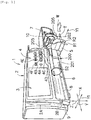
- the syringe pump 1 precisely delivers drug inside a syringe main body 201 to a patient P through a tube 203 and an indwelling needle 204 by pressing a syringe plunger 202 of a syringe 200 which is filled with drug as a drug container, in a T-direction.
- the syringe main body 201 of the syringe 200 is set to the syringe pump 1 so as not to be moved by a clamp 5.
- the syringe pump 1 has a main body cover 2.
- the main body cover 2 is integrally molded of a molding resin material resistant to chemicals. Therefore, the main body cover 2 has a splash-proof treatment structure. On account of the splash-proof treatment structure, it is possible to prevent drug or the like from penetrating into the syringe pump 1 even in a case where the drug is splashed over the syringe pump 1.
- the splash-proof treatment structure is provided because there may be a case where drug inside the syringe main body 201 is spilt or antiseptic solutions or the like used in the vicinity thereof may be splashed to adhere.
- the main body cover 2 has an upper portion 2A and a lower portion 2B.
- a display unit 3 and an operation panel section 4 are arranged in the upper portion 2A.
- a syringe setting portion 6 and a syringe plunger drive unit 7 which presses the syringe plunger 202 are arranged in the lower portion 2B.
- the display unit 3 is an image display device capable of color display.
- the display unit 3 can be formed with a color liquid crystal display device.
- the display unit 3 can display information not only by notation in Japanese but also by notation in multiple foreign languages as necessary.
- the display unit 3 is arranged at a position to the upper left in the upper portion 2A of the main body cover 2, that is, on the upper side of the syringe setting portion 6 and the syringe plunger drive unit 7.
- the operation panel section 4 is arranged on the right side of the display unit 3 in the upper portion of the main body cover 2.
- a power ON/OFF button 4F, a motion indicator 4A, and operation buttons are arranged in an operation panel section 4.
- Figs. 1 and 2 show an example in which four operation buttons of a fast-forward switch button 4B, a start switch button 4C, a stop switch button 4D, and a menu selection button 4E are arranged as the minimum required operation buttons.
- the syringe setting portion 6 and the syringe plunger drive unit 7 are arranged side by side along an X-direction.
- a syringe is selected from syringes 200, 300, and 400 which are different from one another in multiple types of size so as to be able to fit into the syringe setting portion 6 and to be detachably fixed thereto.
- the syringes 200, 300, and 400 will be described later with reference to Fig. 4 .
- the syringe setting portion 6 has an accommodation portion 8 which accommodates the syringe main body 201, and the clamp 5.
- the accommodation portion 8 is a concave portion having a substantially semicircular cross section so as to accommodate the syringe main body 201 and is formed along the X-direction.
- a tube fixing portion 9 is formed on a wall at an end portion of the accommodation portion 8 so as to detachably pinch the tube 203.
- the clamp 5 When detaching the syringe 200 from the syringe setting portion 6 by operating the clamp 5, the clamp 5 is pulled out against a force of a spring (not illustrated) in a Y1-direction (a front direction) and is turned by 90 degrees in an R1-direction so that the syringe main body 201 fixed by the clamp 5 can be released and detached from the accommodation portion 8.
- a spring not illustrated
- the clamp 5 When attaching the syringe 200 to the syringe setting portion 6 by operating the clamp 5, the clamp 5 is pulled out against a force of a spring (not illustrated) in the Y1-direction, is turned by 90 degrees in an R2-direction, and returns in a Y2-direction by a force of the spring so that the syringe main body 201 can be accommodated in the accommodation portion 8 and be fixed by the clamp 5.
- a right end portion 8E of the accommodation portion 8 in the syringe setting portion 6 is partially formed to have a notch portion.
- the syringe plunger 202 is arranged in the syringe plunger drive unit 7.
- the syringe plunger drive unit 7 has a slider 10.
- the slider 10 gradually presses a plunger flange 205 of the syringe plunger 202 relatively along a T-direction with respect to the syringe main body 201, in response to a command from a control unit 100 illustrated in Figs. 2 and 5 .
- X-direction, the Y-directions, and a Z-direction in Figs. 1 and 2 are orthogonal to one another.
- the Z-direction is a vertical direction.
- Fig. 3 illustrates a display example of the display unit 3.
- the display example of the display unit 3 is an example, and thus, the embodiment is not particularly limited thereto.
- Fig. 4 is a perspective view illustrating examples of the above-described syringes in multiple types of size.
- Figs. 1 and 2 illustrate examples in which the syringe 200 having the largest capacity for drug is fixed.
- the syringe 200 having the largest capacity for drug includes the syringe main body 201 and the syringe plunger 202.
- the syringe main body 201 has a main body flange 209, and the syringe plunger 202 has the plunger flange 205.
- a scale 210 for drug is formed in the syringe main body 201.
- One end portion of a flexible tube 203 is detachably connected to an outlet portion 211 of the syringe main body 201.
- the syringe 300 having an intermediate capacity for drug includes a syringe main body 301 and a syringe plunger 302.
- the syringe main body 301 has a main body flange 309, and the syringe plunger 302 has a plunger flange 305.
- a scale 310 for drug is formed in the syringe main body 301.
- the one end portion of the flexible tube 203 is detachably connected to an outlet portion 311 of the syringe main body 301.
- the syringe 400 having the smallest capacity for drug includes a syringe main body 401 and a syringe plunger 402.
- the syringe main body 401 has a main body flange 409, and the syringe plunger 402 has a plunger flange 405.
- a scale 410 for drug is formed in the syringe main body 401.
- the one end portion of the flexible tube 203 is detachably connected to an outlet portion 411 of the syringe main body 401.
- the syringe 200 illustrated in Fig. 4(A) has a capacity of 50 mL for drug.
- the syringe 300 illustrated in Fig. 4(B) has capacities of 10 mL, 20 mL, and 30 mL for drug.
- the syringe 400 illustrated in Fig. 4(C) has capacities of 2.5 mL and 5 mL for drug.
- the syringes 300 and 400 can be used by being accommodated in the accommodation portion 8 and fixed thereto, similarly to the syringe 200 illustrated in Figs. 1 and 2 .
- the syringe pump 1 has a control unit (a computer) 100 which performs judging and controlling of overall operations.
- the control unit 100 is, for example, a one-chip microcomputer and has a ROM (read only memory) 101, a RAM (random access memory) 102, a non-volatile memory 103, and a clock 104.
- the clock 104 can correct a current time, can acquire the current time, can measure an elapsed time for predetermined liquid delivering, and can measure a reference time for controlling a speed of liquid delivering by performing predetermined operations, for example.
- the power ON/OFF button 4F and a switch 111 are connected to the control unit 100 illustrated in Fig. 5 .
- the switch 111 allows a power source to be supplied to the control unit 100 from either a power source converter 112 or a rechargeable battery 113, a lithium-ion battery for example, by switching between the power source converter 112 and the rechargeable battery 113.
- the power source converter 112 is connected to a commercial AC power source 115 through a power plug 114.
- the fast-forward switch button 4B, the start switch button 4C, the stop switch button 4D, and the menu selection button 4E are electrically connected to the control unit 100.
- a control signal to start liquid delivering is input to the control unit 100.
- a control signal to stop liquid delivering is input to the control unit 100.
- a display unit driver 130 is electrically connected to the control unit 100.
- the display unit driver 130 drives the display unit 3 in response to a command from the control unit 100, thereby causing the display unit 3 to display various types of information.
- a speaker 131 is electrically connected to the control unit 100.
- the speaker 131 notifies a user of various types of audio alarms in response to a command from the control unit 100.
- a pair of detection switches 120 and 121 are arranged in the accommodation portion 8.
- the detection switches 120 and 121 detect whether or not the syringe main body 201 of the syringe 200 is properly arranged in the accommodation portion 8, thereby notifying the control unit 100 thereof.
- a clamp sensor 122 detects a positional state of the clamp 5 and notifies the control unit 100 of whether or not the syringe main body 201 is securely clamped by the clamp 5.
- the motor 133 of the syringe plunger drive unit 7 is driven by a motor driver 134 in response to a command from the control unit 100, the motor 133 rotates a feed screw 135, thereby moving the slider 10 in the T-direction.
- the slider 10 precisely delivers drug inside the syringe main body 201 illustrated in Fig. 2 to the patient P through the tube 203 and the indwelling needle 204 by pressing the syringe plunger 202 in the T-direction.
- an acceleration sensor 160 is connected to the control unit 100.
- the acceleration sensor 160 measures acceleration applied to the syringe pump 1 and notifies the control unit 100 thereof.
- the non-volatile memory 103 functions as a storage unit which stores a drug library so as to be updatable.
- a proper value or an upper limit value for a flow rate of liquid to be delivered or a proper value or an upper limit value for an infusion rate of drug is prescribed for each type of drug.
- drug needs to be delivered in accordance with the various parameters such as the proper value or the upper limit value.
- the drug library is a file in which various parameters prescribed in accordance with the type of drug are recorded.
- a method of storing the drug library in the non-volatile memory 103 is not particularly limited.
- the drug library can be stored through a communication port 140.
- a computer 141 such as a desktop computer is connected to the control unit 100 through the communication port 140.
- the computer 141 is connected to drug database 150.
- the drug library is kept in the drug database 150.
- the drug library kept in the drug database 150 can be stored in the non-volatile memory 103 through the communication port 140 by operating the computer 141.
- the drug library is updated in cases as described below. That is, the drug library is updated when adding a new type of drug and when updating, adding, and deleting information related to the types of drug which have already been kept.
- the drug library stored in the non-volatile memory 103 can be also updated by the method of using the communication port 140 and the computer 141 described above.
- the control unit 100 controls the motor driver 134 so as to deliver liquid in accordance with the various parameters with reference to information of the drug library stored in the non-volatile memory 103.
- the type of drug which fills the syringe main body 201 set to the syringe setting portion 6 needs to be selected from the types of drug recorded in the drug library and input to the control unit 100 in advance.
- the types of drug amounting to thousands of types can be recorded in the drug library. Therefore, as the types of drug recorded in the drug library increase, the time taken for selecting the type of drug which fills the syringe main body 201 from the drug library increases.
- the profile can be generated in multiple numbers in accordance with the purpose of use of the syringe pump 1.
- the non-volatile memory 103 can store a plurality of the profiles so as to be updatable.
- the profile stored in the non-volatile memory 103 can be generated by operating the operation buttons of the operation panel section 4 in accordance with display contents of the display unit 3.
- Figs. 6(A) and 6(B) illustrate examples of the display contents of the display unit 3 at the time of generating the profile.
- the profile can be generated by operating the operation buttons of the operation panel section 4 in accordance with the examples of the display contents illustrated in Fig. 6 .
- the display unit 3 exhibits a scroll-type display of the types of drug stored in the drug library.
- the operation buttons of the operation panel section 4 are operated in order to select a suitable type of drug from the types of drug displayed on the display unit 3 in accordance with the purpose of use, or the like.
- the selected type of drug is stored in the non-volatile memory 103 as the profile.
- the profile is also possible to generate the profile so as to be recorded in the drug library by using the computer 141.
- the profile is simultaneously stored in the non-volatile memory 103.
- the profile stored in the non-volatile memory 103 can be set to have a name.
- the names can be set as, for example, Intensive Care Unit (ICU), Coronary Care Unit (CCU), Neonatal Intensive Care Unit (NICU), and Stroke Care Unit (SCU).
- the name of a hospital ward can be set as the profile name.
- the profile is updated in cases as described below. That is, the profile is updated when adding a new type of drug and when deleting the types of drug which has already been recorded.
- the profile stored in the non-volatile memory 103 can be also updated by operating the operation buttons of the operation panel section 4 in accordance with the display contents of the display unit 3.
- the drug library having information of the updated profile recorded therein is stored in the non-volatile memory 103 by a method using the communication port 140 and the computer 141 as described above, and thus, the profile stored in the non-volatile memory 103 can be also updated.
- the profile can be selected from the plurality of profiles stored in the non-volatile memory 103 so as to be applied to the syringe pump 1 in accordance with the purpose of use.
- the profile applied to the syringe pump 1 can be selected by operating the operation buttons of the operation panel section 4 in accordance with the display contents of the display unit 3.
- Figs. 7(A) and 7(B) illustrate examples of the display contents of the display unit 3 at the time of selecting the profile to be applied to the syringe pump 1.
- the display unit 3 exhibits a scroll-type display of the names set in the profile which are stored in the non-volatile memory 103.
- the operation buttons of the operation panel section 4 are operated in accordance with the examples of the display contents illustrated in Figs. 7(A) and 7(B) , and thus, it is possible to select the profile to be applied.
- the non-volatile memory 103 stores information which specifies a profile selected as the profile to be applied to the syringe pump 1.
- the display unit 3 displays a reception screen 40 for receiving selection of the type of drug which fills the syringe main body 201 set to the syringe setting portion 6.
- the operation buttons of the operation panel section 4 are operated in accordance with the display contents of the display unit 3, and thus, the type of drug which fills the syringe main body 201 can be input to the control unit 100.
- Figs. 8(A) and 8(B) illustrate examples of the display contents of the display unit 3 at the time of displaying the reception screen 40 for receiving selection of the type of drug which fills the syringe main body 201.
- the display unit 3 displays a list 41 of the types of drug which is generated by narrowing the types of drug recorded in the drug library, based on the profile selected as the profile to be applied. Accordingly, it is possible to promptly select the type of drug to be delivered and to input to the control unit 100 in accordance with the purpose of use.
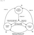
- the syringe pump 1 has three starting states such as a liquid deliverable state S1, a power-OFF state S2, and the standby state S3.
- the liquid deliverable state S1 denotes a starting state where all operations related to delivering of drug can be performed.
- the power-OFF state S2 denotes a state where no operation is accepted excluding pressing of the power ON/OFF button 4F.
- the standby state S3 denotes a state where the rechargeable battery 113 is charged through a power source supplied from the power source converter 112, while in a state where no operation is accepted excluding pressing of the power ON/OFF button 4F.
- Fig. 9 is a state transition diagram related to the starting states of the syringe pump 1.
- the starting state transfers to the power-OFF state S2 when the rechargeable battery 113 supplies a power source to the control unit 100, and the starting state transfers to the standby state S3 when the power source converter 112 supplies a power source to the control unit 100.
- the power ON/OFF button 4F is pressed so that a power source is turned ON while in the power-OFF state S2 or the standby state S3
- the starting state transfers to the liquid deliverable state S1.
- the starting state transfers to the standby state S3.
- the starting state transfers to the power-OFF state S2.
- Turning ON and OFF of a power source is operated by pressing the power ON/OFF button 4F.
- the power supply with respect to the control unit 100 is switched by the switch 111.
- the control unit 100 executes minimal functions necessary to transfer to the liquid deliverable state S1, while in the power-OFF state S2 or the standby state S3.
- the functions executed by the control unit 100 while in the power-OFF state S2 and the standby state S3 include at least a reception of pressing of the power ON/OFF button 4F and a reception of notification of acceleration measured by the acceleration sensor 160.
- the syringe pump 1 is kept in an ME (medical engineer) room and the like when not in use for liquid deliver.
- the syringe pump 1 is in the standby state S3 while kept in the ME room so as to be able to be promptly used when necessary.
- the syringe pump 1 there is a need to check whether or not the syringe pump 1 is a suitable pump for use before being carried to a site used for delivering liquid. At least, it is necessary to check whether or not the drug library stored in the non-volatile memory 103 is suitable for use.
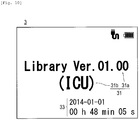
- the display unit 3 displays specification information 31 which specifies a drug library stored in the non-volatile memory 103 while in the standby state S3.
- the specification information 31 which specifies a drug library is configured to include updated identification information 31a of the drug library and information 31b which specifies an applied profile applied to the syringe pump 1.
- the specification information 31 which specifies a drug library can vary depending on objects. Arbitrary information can be used as the specification information 31 as long as the information can be used for discriminating whether or not the pump is suitable for use.
- a library name may be set to the drug library as the unique name, thereby using the library name as the specification information 31 which specifies a drug library.
- the updated identification information 31a of the drug library is caused to use a version number which is applied to the drug library in accordance with the time when the drug library is generated or updated.
- the embodiment is not limited thereto.
- Arbitrary information can be used as the updated identification information 31a of the drug library as long as it can be discriminated whether or not the drug library stored in the non-volatile memory 103 is appropriately updated.
- a profile name is used which is set to the applied profile as the information 31b which specifies an applied profile.
- the embodiment is not limited thereto.
- Arbitrary information can be used as the information 31b which specifies an applied profile as long as the information is the information which specifies the profile applied to the syringe pump 1.
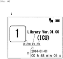
- Fig. 10 illustrates an example of the display contents of the display unit 3 at the time of displaying the specification information 31 which specifies a drug library including the updated identification information 31a of the drug library and the information 31b which specifies an applied profile while in the standby state S3.
- the display unit 3 displays the specification information 31 which specifies a drug library while in the standby state S3, it is possible to judge whether or not a pump is suitable for use while in the standby state S3. Therefore, the syringe pump 1 can be efficiently managed and utilized in the ME room and the like without relying on a complicated method such as attaching of a label.
- the specification information 31 which specifies a drug library includes the updated identification information 31a of the drug library, it is possible to discriminate whether or not the drug library stored in the non-volatile memory 103 is appropriately updated while in the standby state S3. As a result, it is possible to discriminate whether or not the syringe pump 1 can deliver liquid while in the standby state S3 based on appropriate information, thereby improving convenience. Specifically, if the drug library stored in the non-volatile memory 103 is not appropriately updated, various parameters such as a proper value or an upper limit value for a flow rate of liquid to be delivered or a proper value or an upper limit value for an infusion rate of drug may be erroneously set.
- the specification information 31 includes the updated identification information 31a of the drug library.
- the updated identification information 31a of the drug library is information through which a user can discriminate whether or not the drug library is appropriately updated. Therefore, in the syringe pump 1, it is possible to discriminate whether or not the drug library stored in the non-volatile memory 103 is appropriately updated while in the standby state S3. As a result, it is possible to discriminate whether or not the syringe pump 1 can deliver liquid, while in the standby state S3 based on appropriate information, thereby improving convenience.
- the specification information 31 which specifies a drug library includes the information 31b which specifies an applied profile, it is possible to discriminate whether or not information of drug suitable for use is recorded in the drug library which is stored in the non-volatile memory 103, while in the standby state S3.
- the specification information 31 which specifies a drug library includes the information 31b which specifies an applied profile, it is also possible to simultaneously discriminate whether or not the types of drug suitable for use can be promptly selected by the syringe pump 1, while in the standby state S3, thereby further improving convenience.
- the profile is a file having a result recorded therein in which the types of drug recorded in the drug library are narrowed in accordance with the purpose of use.
- the display unit 3 displays the list 41 of the types of drug which is generated by narrowing the types of drug recorded in the drug library, based on the applied profile. Accordingly, it is possible to promptly select the type of drug to be delivered, in accordance with the purpose of use.
- the information 31b which specifies an applied profile it is possible to discriminate whether or not the type of drug suitable for use can be promptly selected by the syringe pump 1, while in the standby state S3, thereby further improving convenience.
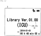
- the display unit 3 includes a power mode switching unit which switches a power mode between a normal power mode and an energy-saving power mode in which less power is consumed than the normal power mode and information is displayed so as to be visually recognizable when displaying the information, while in the standby state S3.
- the power mode switching unit switches the power mode from the normal power mode to the energy-saving power mode when no operation is performed with respect to the syringe pump 1 for a predetermined time while in the normal power mode.
- the power mode switching unit switches the power mode from the energy-saving power mode to the normal power mode when buttons other than the power ON/OFF button 4F are pressed while in the energy-saving power mode.
- Fig. 11 illustrates an example of the display contents of the display unit 3 when the specification information 31 which specifies a drug library including the updated identification information 31a of the drug library and the information 31b which specifies an applied profile is displayed in low luminance.
- the display unit 3 has the power mode switching unit, power consumption is decreased when displaying information necessary to discriminate whether or not the pump is suitable for use while in the standby state S3, and thus, a pump can be efficiently managed and utilized.
- the display unit 3 may display information 33 of the calendar when displaying the specification information 31 which specifies a drug library stored in the non-volatile memory 103.
- the display unit 3 can display information related to a current time as the information 33 of the calendar.
- the medical pump is periodically inspected.
- periodical inspection consumable components are replaced in accordance with a result of checking whether or not there is abnormality in operations of the medical pump, or utilization time.
- abnormality is found in operations, replacement or repair service of the component is performed. If periodical inspection is not appropriately performed, there may be a disadvantage such as an occurrence of malfunction during liquid delivering leading to a stop of liquid delivering.
- the non-volatile memory 103 functions as the storage unit which stores a periodical inspection time.
- the display unit 3 displays information 34 which notifies a user of an arrival state of the periodical inspection time, while in the standby state S3.
- Judging of an arrival state of the periodical inspection time can be performed by the control unit 100 as described below, for example. In other words, it is possible to judge the arrival state by comparing a current time acquired from the clock 104 and the periodical inspection time stored in the non-volatile memory 103.
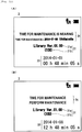
- Figs. 12 (A) and 12 (B) illustrate examples of the display contents of the display unit 3 when displaying an arrival state of the periodical inspection time.
- Fig. 12(A) illustrates the example of the display contents when displaying information notifying that the periodical inspection time is nearing.
- Fig. 12(B) illustrates the example of the display contents when displaying information notifying that the current time has passed the periodical inspection time.
- the display unit 3 may display the specification information 31 which specifies a drug library including the updated identification information 31a of the drug library and the information 31b which specifies an applied profile together with the information 34 which notifies a user of an arrival state of the periodical inspection time.
- the periodical inspection time stored in the non-volatile memory 103 can be appropriately set by a health care worker who manages the syringe pump 1. It is also possible to appropriately set the time for displaying the information notifying that the periodical inspection time is nearing. For example, the time may be set to display the information when the period from the current time to the periodical inspection time is less than one week, or may be set to display the information when the period is less than two weeks.
- the display unit 3 displays the information 34 which notifies a user of an arrival state of the periodical inspection time, while in the standby state S3, it is possible to discriminate whether or not periodic inspection is appropriately performed, while in the standby state S3.
- the medical pump needs to precisely deliver drug in accordance with the various parameters prescribed for each type of drug. Accordingly, components used in the medical pump may include a highly precise component, which may break down or be damaged by an external shock. In a case of break-down or damage occurring in the component, there may be a disadvantage that liquid delivering is not precisely performed in accordance with the various parameters prescribed for each type of drug.
- the acceleration sensor 160 functions as a shock detection unit which detects whether or not a shock is applied to the syringe pump 1.
- the display unit 3 displays information 35 which notifies a user of whether or not a shock is detected by the acceleration sensor 160, while in the standby state S3.
- control unit 100 receives notification of acceleration measured by the acceleration sensor 160 in all starting states.
- control unit 100 can detect a shock not only in the liquid deliverable state S1 but also in the power-OFF state S2 and the standby state S3.
- Fig. 13 illustrates an example of the display contents of the display unit 3 when displaying the information 35 which notifies a user that a shock is detected by the acceleration sensor 160, while in the standby state S3.
- the display unit 3 displays the information 35 which notifies a user that a shock is detected by the acceleration sensor 160, while in the standby state S3, it is possible to discriminate whether or not a shock is detected, while in the standby state S3.
- the display unit 3 may display information which notifies a user that a shock is detected by the acceleration sensor 160, while in the power-OFF state S2 as well.
- the display unit 3 may display the specification information 31 which specifies a drug library including the updated identification information 31a of the drug library and the information 31b which specifies an applied profile together with the information 35 which notifies a user that a shock is detected.
- the display unit 3 may display the specification information 31 which specifies a drug library on the reception screen 40 which receives selection of the type of drug which fills the syringe main body 201.
- Figs. 8 (A) and 8 (B) illustrate an example of the display contents of the display unit 3 when displaying the specification information 31 which specifies a drug library including the updated identification information 31a of the drug library and the information 31b which specifies an applied profile on the reception screen 40 which receives selection of the type of drug which fills the syringe main body 201.
- the specification information 31 which specifies a drug library is displayed on the reception screen 40, it is possible to prevent a pump not suitable for use from being used, thereby improving safety.
- various parameters such as a proper value or an upper limit value for a flow rate of liquid to be delivered or a proper value or an upper limit value for an infusion rate of drug may be erroneously set.
- the specification information 31 displayed on the reception screen 40 includes the updated identification information 31a of the drug library, it is possible to prevent the various parameters from being erroneously set.
- the list 41 of the types of drug not suitable for use is displayed on the reception screen 40 which receives selection of the types of drug. Since some types of drug have names similar to one another and the list 41 of the types of drug not suitable for use is displayed, a possibility to erroneously select the type of drug to be delivered increases. As the specification information 31 displayed on the reception screen 40 includes the information 31b which specifies an applied profile, it is possible to prevent such erroneous selection.
- the power ON/OFF button 4F is pressed so as to be in the liquid deliverable state S1.
- control unit 100 and the computer 141 are connected to each other through the communication port 140.
- the computer 141 is operated, and a drug library including information of the plurality of profiles is input to the control unit 100 from the drug database 150 through the communication port 140.
- the drug library and the plurality of profiles recorded in the drug library are stored in the non-volatile memory 103.
- the operation buttons of the operation panel section 4 are operated in accordance with the display contents of the display unit 3 as described in Fig. 7 , thereby selecting the profile to be applied in accordance with the purpose of use.
- the power ON/OFF button 4F is pressed so as to turn the power source OFF.
- the syringe pump 1 is moved to a suitable keeping place in the ME room.
- the power plug 114 is connected to the commercial AC power source 115 installed in the keeping place.
- the syringe pump 1 is in the standby state S3.
- the syringe pump 1 is carried to a site used for delivering drug upon request from a site such as the intensive care unit (ICU) and the like. In this case, there is a need to select a syringe pump 1 suitable for use out of the plurality of syringe pumps 1 kept in the ME room so as to be carried to the site.
- ICU intensive care unit
- Selection of the syringe pump 1 suitable for use is performed in accordance with the information displayed on the display unit 3.
- the display unit 3 displays the specification information 31 which specifies a drug library including the updated identification information 31a of the drug library and the information 31b which specifies an applied profile, while in the standby state S3, and in the normal power mode or the energy-saving power mode.
- the display unit 3 displays the information 34 which notifies a user of an arrival state of the periodical inspection time in accordance with the arrival state of the periodical inspection time.
- the display unit 3 displays the information 35 which notifies a user that a shock is applied.
- Whether or not the pump can be used for delivering liquid is checked from the information displayed on the display unit 3.
- the display unit 3 displays the information 34 which notifies a user of an arrival state of the periodical inspection time and the information 35 which notifies a user that a shock is applied, while in the standby state S3, it is possible to promptly check whether or not the pump can be appropriately used for delivering liquid.
- the syringe pump 1 After selecting a pump which is suitable for use and can be appropriately used for delivering liquid, the syringe pump 1 is carried to a site used for delivering liquid.
- the syringe 200 is set to the syringe pump 1.
- the syringe pump 1 is set by the above-described method using the clamp 5.
- the type of drug which fills the syringe main body 201 is selected by operating the operation buttons of the operation panel section 4 in accordance with the display contents of the reception screen 40 which is displayed on the display unit 3 as illustrated in Fig. 8 .
- the specification information 31 which specifies a drug library including the updated identification information 31a of the drug library and the information 31b which specifies an applied profile is displayed on the display unit 3.
- the displayed information is checked whether or not the drug library stored in the non-volatile memory 103 and the applied profile are suitable for use. If the drug library and the applied profile are not suitable for use, it is judged whether or not the process is continued in consideration of urgency. If the process is not continued, another syringe pump 1 suitable for use is carried from the ME room, thereby restarting the process.
- the indwelling needle 204 having the tube 203 connected thereto is inserted into the patient P.
- the operation buttons of the operation panel section 4 are operated in accordance with the display contents of the display unit 3, thereby inputting gender, age, height, and weight or the like as information of the patient P.
- the start switch button 4C is pressed to start delivering of drug to the inside of the patient P.
- Delivering of drug is performed in accordance with various parameters recorded in the drug library stored in the non-volatile memory 103 and in accordance with the type of selected drug.
- the syringe pump 1 After delivering drug is completed, the syringe pump 1 is returned to and kept in the ME room for the next use.
- the information 31 which specifies a drug library stored in the non-volatile memory 103 is displayed on the display unit 3, while in the standby state S3. Accordingly, it is possible to discriminate whether or not a pump is suitable for use, while in the standby state S3. Therefore, according to the present embodiment, it is possible to provide a liquid delivering pump which can be efficiently managed and utilized.
- the specification information 31 which specifies a drug library includes the updated identification information 31a of the drug library. Therefore, it is possible to discriminate whether or not the drug library stored in the non-volatile memory 103 is appropriately updated, while in the standby state S3. Thus, according to the present embodiment, it is possible to discriminate whether or not the pump can deliver liquid, while in the standby state S3 based on appropriate information, thereby improving convenience.
- the specification information 31 which specifies a drug library includes information which specifies the profile applied to the syringe pump 1. Therefore, it is possible to discriminate whether or not information of drug suitable for use is recorded in the drug library stored in the non-volatile memory 103, while in the standby state S3. Moreover, it is also possible to discriminate whether or not the type of drug suitable for use can be promptly selected by the pump, while in the standby state S3, thereby further improving convenience.
- the non-volatile memory 103 stores the periodical inspection time.
- the display unit 3 displays the information 34 which notifies a user of an arrival state of the periodical inspection time, while in the standby state S3. Accordingly, it is possible to discriminate whether or not the periodical inspection is appropriately performed, while in the standby state S3. Thus, a pump can be more efficiently managed and utilized.
- the acceleration sensor 160 functions as the shock detection unit which detects whether or not the pump is subjected to a shock.
- the display unit 3 displays the information 35 which notifies a user of whether or not a shock is detected, while in the standby state S3. Accordingly, it is possible to discriminate whether or not a shock is detected, while in the standby state S3. Thus, a pump can be further efficiently managed and utilized.
- the display unit 3 includes the power mode switching unit which switches the power mode between the normal power mode and the energy-saving power mode in which less power is consumed than the normal power mode and the specification information 31 is displayed so as to be visually recognizable when displaying the specification information 31 which specifies a drug library, while in the standby state S3.
- the power mode switching unit switches the power mode from the normal power mode to the energy-saving power mode when no operation is performed with respect to the syringe pump 1 for a predetermined time while in the normal power mode. Accordingly, it is possible to decrease power consumption when displaying information necessary to discriminate whether or not the pump is suitable for use, while in the standby state S3. Thus, a pump can be more efficiently managed and utilized.
- the display unit 3 displays the reception screen 40 which receives selection of the type of drug to be delivered, while in the liquid deliverable state S1.
- the display unit 3 also displays the specification information 31 which specifies a drug library on the reception screen 40. Accordingly, when selecting a type of drug to be delivered, while in the liquid deliverable state S1, it is possible to discriminate whether or not the pump is suitable for use. Therefore, it is possible to prevent a pump not suitable for use from being used, thereby improving safety.
- the display unit 3 displays the profile name set in the applied profile as the information 31b which specifies the applied profile.
- the embodiment is not limited thereto. As described above, as long as it is possible to discriminate whether or not the profile suitable for use is applied to the syringe pump 1, arbitrary information can be used as the information 31b which specifies the profile.
- the profile IDs may be respectively set so as to cause the plurality of the profiles stored in the non-volatile memory 103 to be identifiable, and a visually identifiable icon 36 may be displayed replacing the profile ID.
- Fig. 14 illustrates an example of the display contents of the display unit 3 when the profile ID is replaced by the icon 36 and the information 31b which specifies an applied profile is displayed.
- the updated identification information 31a of the drug library may be simultaneously displayed when the information 31b which specifies the applied profile is replaced by the icon 36 and displayed thereon.
- the profile name set to the applied profile may be simultaneously displayed together with the icon 36, as the information 31b which specifies the applied profile.
- the example of the display contents illustrated in Fig. 14 indicates a case where serial numbers are set as the profile ID.
- the embodiment is not limited thereto.
- arbitrary signs or information can be used as the profile ID. For example, numerals, alphabets, and other signs can be used as the profile ID.
- the display unit 3 By configuring the display unit 3 as described above, it is possible to visually discriminate whether or not the pump is suitable for use. Therefore, time taken for discrimination is decreased, thereby improving convenience and preventing erroneous identification at the time of discrimination, leading to an improvement of safety.
- the display unit 3 may vary a display state at the time of displaying the specification information 31 which specifies a drug library stored in the non-volatile memory 103 in accordance with the applied profile.
- Figs. 15(A) to 15(C) illustrate examples of the display contents of the display unit 3 when varying a display position at the time of displaying the specification information 31 which specifies a drug library including the updated identification information 31a of the drug library and the information 31b which specifies an applied profile, in accordance with the applied profile.
- serial numbers are set to the plurality of profiles stored in the non-volatile memory 103 as the profile IDs causing each profile to be identifiable.
- Fig. 15(A) illustrates an example of the display contents in a case where the remainder is 1 when the number of the profile IDs of the applied profiles is divided by 3.
- Fig. 15(B) illustrates an example of the display contents in a case where the remainder is 2 when the number of the profile IDs of the applied profiles is divided by 3.
- Fig. 15(C) illustrates an example of the display contents in a case where the remainder is zero when the number of the profile IDs of the applied profiles is divided by 3.
- the display position of the specification information 31 which specifies a drug library including the updated identification information 31a of the drug library and the information 31b which specifies an applied profile is varied respectively to the left end, to the center, and to the right end in the display unit 3.
- the embodiment is not limited thereto.
- the position may be varied to the top, to the center, and to the bottom in the display unit 3 in accordance with the applied profile.
- the display position of the specification information 31 which specifies a drug library including the updated identification information 31a of the drug library and the information 31b which specifies an applied profile is varied in accordance with the applied profile.
- the embodiment is not limited thereto.
- the color and size at the time of displaying the specification information 31 which specifies a drug library stored in the non-volatile memory 103 may be varied.
- the display unit 3 By configuring the display unit 3 as described above, it is possible to easily identify the applied profile. Therefore, it is possible to decrease erroneous identification at the time of discriminating whether or not the profile suitable for use is applied, thereby further improving convenience and safety.
- the display state at the time of displaying the specification information 31 which specifies a drug library stored in the non-volatile memory 103 may be varied in accordance with an elapsed time from an update of the drug library.
- Figs. 16(A) to 16(C) illustrate examples of the display contents of the display unit 3 when varying a display color at the time of displaying the specification information 31 which specifies a drug library including the updated identification information 31a of the drug library and the information 31b which specifies an applied profile in accordance with an elapsed time from an update of the drug library.
- Fig. 16(A) illustrates an example of the display contents in a case where the elapsed time from an update of the drug library is within one day.
- Fig. 16(B) illustrates an example of the display contents in a case where the elapsed time from an update of the drug library ranges from one day to one week.
- Fig. 16(C) illustrates an example of the display contents in a case where the elapsed time from an update of the drug library is equal to or exceeding one week.
- the display color is caused to fade in the order of those in Fig. 16(A), Fig. 16(B), and Fig. 16(C) .
- the embodiment is not limited thereto.
- the display color may be caused to be darker in the order of those in Fig. 16(A), Fig. 16(B), and Fig. 16(C) . Otherwise, the display color may be varied to different colors such as red, green, black, and the like.
- the display colors of both the updated identification information 31a of the drug library and the information 31b which specifies an applied profile are varied. However, either one of the display colors may be varied.
- the display colors of the specification information 31 which specifies a drug library is varied by dividing the elapsed time from an update of the drug library into three terms.
- the terms to be varied in display color can be arbitrarily set.
- the display colors may be varied by dividing the elapsed time from an update of the drug library into two terms such as a term of within one week and a term of equal to or exceeding one week.
- the display color of the specification information 31 which specifies a drug library is varied in accordance with an elapsed time from an update of the drug library.
- the embodiment is not limited thereto.
- the display position or size at the time of displaying the specification information 31 which specifies a drug library may be varied. Elapsed days or the elapsed time from an update of the drug library may be displayed numerically.
- the display unit 3 By configuring the display unit 3 as described above, it is possible to easily identify the elapsed time from an update of the drug library stored in the non-volatile memory 103. Accordingly, it is possible to decrease erroneous identification when discriminating whether or not the drug library stored in the non-volatile memory 103 is appropriately updated, thereby further improving convenience and safety.
- liquid delivering pump according to the present invention has been described through the embodiment and each of the modification examples.
- the liquid delivering pump according to the present invention is not limited to only the configurations thereof and it is possible to make various changes and modifications based on the disclosed scope of Claims.
- the present invention is not limited thereto.
- the present invention can be widely applied to medical liquid delivering pumps such as infusion pumps in which an amount of drug to be delivered can be adjusted.
Applications Claiming Priority (1)
| Application Number | Priority Date | Filing Date | Title |
|---|---|---|---|
| JP2014058603A JP6360332B2 (ja) | 2014-03-20 | 2014-03-20 | 送液ポンプ |
Publications (3)
| Publication Number | Publication Date |
|---|---|
| EP2921190A2 EP2921190A2 (en) | 2015-09-23 |
| EP2921190A3 EP2921190A3 (en) | 2015-11-11 |
| EP2921190B1 true EP2921190B1 (en) | 2018-10-03 |
Family
ID=52669544
Family Applications (1)
| Application Number | Title | Priority Date | Filing Date |
|---|---|---|---|
| EP15159131.0A Active EP2921190B1 (en) | 2014-03-20 | 2015-03-16 | Liquid delivering pump |
Country Status (4)
| Country | Link |
|---|---|
| US (1) | US10195339B2 (ja) |
| EP (1) | EP2921190B1 (ja) |
| JP (1) | JP6360332B2 (ja) |
| CN (1) | CN104922747B (ja) |
Families Citing this family (13)
| Publication number | Priority date | Publication date | Assignee | Title |
|---|---|---|---|---|
| USD767756S1 (en) | 2013-06-11 | 2016-09-27 | Deka Products Limited Partnership | Medical pump |
| USD735319S1 (en) | 2013-06-11 | 2015-07-28 | Deka Products Limited Partnership | Medical pump |
| USD736370S1 (en) | 2013-06-11 | 2015-08-11 | Deka Products Limited Partnership | Medical pump |
| USD760782S1 (en) | 2013-12-20 | 2016-07-05 | Deka Products Limited Partnership | Display screen of a medical pump with a graphical user interface |
| USD803386S1 (en) * | 2015-02-10 | 2017-11-21 | Deka Products Limited Partnership | Syringe medical pump |
| USD803387S1 (en) * | 2015-02-10 | 2017-11-21 | Deka Products Limited Partnership | Syringe medical pump |
| USD805183S1 (en) | 2015-02-10 | 2017-12-12 | Deka Products Limited Partnership | Medical pump |
| USD801519S1 (en) | 2015-02-10 | 2017-10-31 | Deka Products Limited Partnership | Peristaltic medical pump |
| USD894373S1 (en) * | 2015-09-30 | 2020-08-25 | Fresenius Vial Sas | Syringe pump |
| JP6643903B2 (ja) * | 2016-01-12 | 2020-02-12 | 株式会社テクトロン | 医療機器の点検済表示システム及び点検済表示方法 |
| WO2017189167A1 (en) * | 2016-04-28 | 2017-11-02 | Becton, Dickinson And Company | Needle storage magazine with status indication |
| CN110944697B (zh) | 2017-07-19 | 2022-09-09 | 史密斯医疗Asd公司 | 输液泵的壳体布置 |
| JP7162604B2 (ja) * | 2017-09-29 | 2022-10-28 | テルモ株式会社 | 医療用ポンプ、医療用ポンプの制御方法、及び医療用ポンプシステム |
Family Cites Families (19)
| Publication number | Priority date | Publication date | Assignee | Title |
|---|---|---|---|---|
| US4587967A (en) * | 1985-07-09 | 1986-05-13 | Lifecare Services, Inc. | Oxygen enriched reciprocating piston respirator |
| ES2154651T3 (es) * | 1992-10-15 | 2001-04-16 | Gen Hospital Corp | Bomba de infusion con biblioteca de medicamentos cargable electronicamente. |
| EP1205206B1 (en) * | 1994-10-14 | 2003-10-22 | Bird Products Corporation | Exhalation valve |
| US5782805A (en) | 1996-04-10 | 1998-07-21 | Meinzer; Randolph | Medical infusion pump |
| US6554798B1 (en) * | 1998-08-18 | 2003-04-29 | Medtronic Minimed, Inc. | External infusion device with remote programming, bolus estimator and/or vibration alarm capabilities |
| JP4477317B2 (ja) * | 2003-06-25 | 2010-06-09 | テルモ株式会社 | 輸液ポンプ及びシリンジポンプ |
| US7895053B2 (en) * | 2003-10-07 | 2011-02-22 | Hospira, Inc. | Medication management system |
| US8065161B2 (en) * | 2003-11-13 | 2011-11-22 | Hospira, Inc. | System for maintaining drug information and communicating with medication delivery devices |
| CA2548258C (en) * | 2003-12-05 | 2015-11-17 | Cardinal Health 303, Inc. | Patient-controlled analgesia with patient monitoring system |
| US20060258985A1 (en) * | 2005-05-11 | 2006-11-16 | Russell Claudia J | Graphical display of medication limits and delivery program |
| PL1969507T3 (pl) * | 2005-12-19 | 2012-09-28 | Gambro Lundia Ab | Aparat medyczny z ulepszonym interfejsem użytkownika |
| US9798859B2 (en) * | 2006-07-07 | 2017-10-24 | Roche Diabetes Care, Inc | Fluid delivery device and methods of its operation |
| US20080125700A1 (en) * | 2006-11-29 | 2008-05-29 | Moberg Sheldon B | Methods and apparatuses for detecting medical device acceleration, temperature, and humidity conditions |
| US8543416B2 (en) * | 2007-12-18 | 2013-09-24 | Hospira, Inc. | Infusion pump with configurable screen settings |
| CA2710232A1 (en) | 2007-12-21 | 2009-07-09 | Coda Therapeutics, Inc. | Treatment of abnormal or excessive scars |
| CN102105187A (zh) * | 2008-05-30 | 2011-06-22 | 阿勒根公司 | 用于液体或凝胶形式的软组织扩增填充物、生物活性剂和其他生物相容性材料的注射装置 |
| US9953138B2 (en) * | 2010-06-29 | 2018-04-24 | Codman Neuro Sciences Sarl | Drug component admixture library for a drug infusion delivery system |
| JP5881299B2 (ja) * | 2011-02-28 | 2016-03-09 | テルモ株式会社 | 医療用ポンプ |
| US9289551B2 (en) * | 2011-11-10 | 2016-03-22 | Panasonic Healthcare Holdings Co., Ltd. | Pharmaceutical injection device |
-
2014
- 2014-03-20 JP JP2014058603A patent/JP6360332B2/ja active Active
-
2015
- 2015-02-27 CN CN201510089343.4A patent/CN104922747B/zh active Active
- 2015-03-16 EP EP15159131.0A patent/EP2921190B1/en active Active
- 2015-03-19 US US14/663,224 patent/US10195339B2/en active Active
Non-Patent Citations (1)
| Title |
|---|
| None * |
Also Published As
| Publication number | Publication date |
|---|---|
| EP2921190A3 (en) | 2015-11-11 |
| CN104922747A (zh) | 2015-09-23 |
| JP6360332B2 (ja) | 2018-07-18 |
| US10195339B2 (en) | 2019-02-05 |
| CN104922747B (zh) | 2019-09-24 |
| EP2921190A2 (en) | 2015-09-23 |
| JP2015181554A (ja) | 2015-10-22 |
| US20150265763A1 (en) | 2015-09-24 |
Similar Documents
| Publication | Publication Date | Title |
|---|---|---|
| EP2921190B1 (en) | Liquid delivering pump | |
| US10869963B2 (en) | Low-cost ambulatory medical pump | |
| JP6280965B2 (ja) | バッテリ管理システム | |
| US9333291B2 (en) | Infusion pump battery capacity management and battery charge alert system and method | |
| KR100428607B1 (ko) | 의료주입펌프 | |
| JP4769198B2 (ja) | 機械システム | |
| JP7162604B2 (ja) | 医療用ポンプ、医療用ポンプの制御方法、及び医療用ポンプシステム | |
| EP2902049B1 (en) | Equipment mounting device and control method for equipment mounting device | |
| CN107209800A (zh) | 用于运行模式转换的方法以及相关输注设备和系统 | |
| JP5881299B2 (ja) | 医療用ポンプ | |
| EP3378512A1 (en) | Medical pump, method for controlling medical pump, and program for controlling medical pump | |
| WO2015141562A1 (ja) | 送液ポンプ | |
| WO2014033779A1 (ja) | 輸液ポンプのラック装置 | |
| EP3120885A1 (en) | Liquid delivery pump | |
| WO2016118817A1 (en) | Fluid infusion device | |
| WO2019064903A1 (ja) | 医療用ポンプ、医療用ポンプの制御方法、及び医療用ポンプシステム | |
| WO2020149045A1 (ja) | 医療用ポンプ | |
| JP7183169B2 (ja) | 医療用ポンプ、医療用ポンプの制御方法、及び医療用ポンプシステム | |
| JP2015181555A (ja) | 送液ポンプ |
Legal Events
| Date | Code | Title | Description |
|---|---|---|---|
| PUAI | Public reference made under article 153(3) epc to a published international application that has entered the european phase |
Free format text: ORIGINAL CODE: 0009012 |
|
| 17P | Request for examination filed |
Effective date: 20150316 |
|
| AK | Designated contracting states |
Kind code of ref document: A2 Designated state(s): AL AT BE BG CH CY CZ DE DK EE ES FI FR GB GR HR HU IE IS IT LI LT LU LV MC MK MT NL NO PL PT RO RS SE SI SK SM TR |
|
| AX | Request for extension of the european patent |
Extension state: BA ME |
|
| PUAL | Search report despatched |
Free format text: ORIGINAL CODE: 0009013 |
|
| AK | Designated contracting states |
Kind code of ref document: A3 Designated state(s): AL AT BE BG CH CY CZ DE DK EE ES FI FR GB GR HR HU IE IS IT LI LT LU LV MC MK MT NL NO PL PT RO RS SE SI SK SM TR |
|
| AX | Request for extension of the european patent |
Extension state: BA ME |
|
| RIC1 | Information provided on ipc code assigned before grant |
Ipc: A61M 5/145 20060101AFI20151006BHEP Ipc: A61M 5/31 20060101ALN20151006BHEP Ipc: G06F 19/00 20110101ALI20151006BHEP |
|
| STAA | Information on the status of an ep patent application or granted ep patent |
Free format text: STATUS: EXAMINATION IS IN PROGRESS |
|
| 17Q | First examination report despatched |
Effective date: 20170616 |
|
| GRAP | Despatch of communication of intention to grant a patent |
Free format text: ORIGINAL CODE: EPIDOSNIGR1 |
|
| STAA | Information on the status of an ep patent application or granted ep patent |
Free format text: STATUS: GRANT OF PATENT IS INTENDED |
|
| INTG | Intention to grant announced |
Effective date: 20180503 |
|
| GRAS | Grant fee paid |
Free format text: ORIGINAL CODE: EPIDOSNIGR3 |
|
| GRAA | (expected) grant |
Free format text: ORIGINAL CODE: 0009210 |
|
| STAA | Information on the status of an ep patent application or granted ep patent |
Free format text: STATUS: THE PATENT HAS BEEN GRANTED |
|
| AK | Designated contracting states |
Kind code of ref document: B1 Designated state(s): AL AT BE BG CH CY CZ DE DK EE ES FI FR GB GR HR HU IE IS IT LI LT LU LV MC MK MT NL NO PL PT RO RS SE SI SK SM TR |
|
| REG | Reference to a national code |
Ref country code: GB Ref legal event code: FG4D |
|
| REG | Reference to a national code |
Ref country code: CH Ref legal event code: EP Ref country code: AT Ref legal event code: REF Ref document number: 1047948 Country of ref document: AT Kind code of ref document: T Effective date: 20181015 |
|
| REG | Reference to a national code |
Ref country code: IE Ref legal event code: FG4D Ref country code: DE Ref legal event code: R096 Ref document number: 602015017355 Country of ref document: DE |
|
| REG | Reference to a national code |
Ref country code: NL Ref legal event code: MP Effective date: 20181003 |
|
| REG | Reference to a national code |
Ref country code: LT Ref legal event code: MG4D |
|
| REG | Reference to a national code |
Ref country code: AT Ref legal event code: MK05 Ref document number: 1047948 Country of ref document: AT Kind code of ref document: T Effective date: 20181003 |
|
| PG25 | Lapsed in a contracting state [announced via postgrant information from national office to epo] |
Ref country code: NL Free format text: LAPSE BECAUSE OF FAILURE TO SUBMIT A TRANSLATION OF THE DESCRIPTION OR TO PAY THE FEE WITHIN THE PRESCRIBED TIME-LIMIT Effective date: 20181003 |
|
| PG25 | Lapsed in a contracting state [announced via postgrant information from national office to epo] |
Ref country code: IS Free format text: LAPSE BECAUSE OF FAILURE TO SUBMIT A TRANSLATION OF THE DESCRIPTION OR TO PAY THE FEE WITHIN THE PRESCRIBED TIME-LIMIT Effective date: 20190203 Ref country code: BG Free format text: LAPSE BECAUSE OF FAILURE TO SUBMIT A TRANSLATION OF THE DESCRIPTION OR TO PAY THE FEE WITHIN THE PRESCRIBED TIME-LIMIT Effective date: 20190103 Ref country code: FI Free format text: LAPSE BECAUSE OF FAILURE TO SUBMIT A TRANSLATION OF THE DESCRIPTION OR TO PAY THE FEE WITHIN THE PRESCRIBED TIME-LIMIT Effective date: 20181003 Ref country code: LV Free format text: LAPSE BECAUSE OF FAILURE TO SUBMIT A TRANSLATION OF THE DESCRIPTION OR TO PAY THE FEE WITHIN THE PRESCRIBED TIME-LIMIT Effective date: 20181003 Ref country code: ES Free format text: LAPSE BECAUSE OF FAILURE TO SUBMIT A TRANSLATION OF THE DESCRIPTION OR TO PAY THE FEE WITHIN THE PRESCRIBED TIME-LIMIT Effective date: 20181003 Ref country code: AT Free format text: LAPSE BECAUSE OF FAILURE TO SUBMIT A TRANSLATION OF THE DESCRIPTION OR TO PAY THE FEE WITHIN THE PRESCRIBED TIME-LIMIT Effective date: 20181003 Ref country code: HR Free format text: LAPSE BECAUSE OF FAILURE TO SUBMIT A TRANSLATION OF THE DESCRIPTION OR TO PAY THE FEE WITHIN THE PRESCRIBED TIME-LIMIT Effective date: 20181003 Ref country code: PL Free format text: LAPSE BECAUSE OF FAILURE TO SUBMIT A TRANSLATION OF THE DESCRIPTION OR TO PAY THE FEE WITHIN THE PRESCRIBED TIME-LIMIT Effective date: 20181003 Ref country code: LT Free format text: LAPSE BECAUSE OF FAILURE TO SUBMIT A TRANSLATION OF THE DESCRIPTION OR TO PAY THE FEE WITHIN THE PRESCRIBED TIME-LIMIT Effective date: 20181003 Ref country code: NO Free format text: LAPSE BECAUSE OF FAILURE TO SUBMIT A TRANSLATION OF THE DESCRIPTION OR TO PAY THE FEE WITHIN THE PRESCRIBED TIME-LIMIT Effective date: 20190103 Ref country code: CZ Free format text: LAPSE BECAUSE OF FAILURE TO SUBMIT A TRANSLATION OF THE DESCRIPTION OR TO PAY THE FEE WITHIN THE PRESCRIBED TIME-LIMIT Effective date: 20181003 |
|
| PG25 | Lapsed in a contracting state [announced via postgrant information from national office to epo] |
Ref country code: PT Free format text: LAPSE BECAUSE OF FAILURE TO SUBMIT A TRANSLATION OF THE DESCRIPTION OR TO PAY THE FEE WITHIN THE PRESCRIBED TIME-LIMIT Effective date: 20190203 Ref country code: GR Free format text: LAPSE BECAUSE OF FAILURE TO SUBMIT A TRANSLATION OF THE DESCRIPTION OR TO PAY THE FEE WITHIN THE PRESCRIBED TIME-LIMIT Effective date: 20190104 Ref country code: RS Free format text: LAPSE BECAUSE OF FAILURE TO SUBMIT A TRANSLATION OF THE DESCRIPTION OR TO PAY THE FEE WITHIN THE PRESCRIBED TIME-LIMIT Effective date: 20181003 Ref country code: AL Free format text: LAPSE BECAUSE OF FAILURE TO SUBMIT A TRANSLATION OF THE DESCRIPTION OR TO PAY THE FEE WITHIN THE PRESCRIBED TIME-LIMIT Effective date: 20181003 Ref country code: SE Free format text: LAPSE BECAUSE OF FAILURE TO SUBMIT A TRANSLATION OF THE DESCRIPTION OR TO PAY THE FEE WITHIN THE PRESCRIBED TIME-LIMIT Effective date: 20181003 |
|
| REG | Reference to a national code |
Ref country code: DE Ref legal event code: R097 Ref document number: 602015017355 Country of ref document: DE |
|
| PG25 | Lapsed in a contracting state [announced via postgrant information from national office to epo] |
Ref country code: IT Free format text: LAPSE BECAUSE OF FAILURE TO SUBMIT A TRANSLATION OF THE DESCRIPTION OR TO PAY THE FEE WITHIN THE PRESCRIBED TIME-LIMIT Effective date: 20181003 Ref country code: DK Free format text: LAPSE BECAUSE OF FAILURE TO SUBMIT A TRANSLATION OF THE DESCRIPTION OR TO PAY THE FEE WITHIN THE PRESCRIBED TIME-LIMIT Effective date: 20181003 |
|
| PLBE | No opposition filed within time limit |
Free format text: ORIGINAL CODE: 0009261 |
|
| STAA | Information on the status of an ep patent application or granted ep patent |
Free format text: STATUS: NO OPPOSITION FILED WITHIN TIME LIMIT |
|
| PG25 | Lapsed in a contracting state [announced via postgrant information from national office to epo] |
Ref country code: EE Free format text: LAPSE BECAUSE OF FAILURE TO SUBMIT A TRANSLATION OF THE DESCRIPTION OR TO PAY THE FEE WITHIN THE PRESCRIBED TIME-LIMIT Effective date: 20181003 Ref country code: SM Free format text: LAPSE BECAUSE OF FAILURE TO SUBMIT A TRANSLATION OF THE DESCRIPTION OR TO PAY THE FEE WITHIN THE PRESCRIBED TIME-LIMIT Effective date: 20181003 Ref country code: RO Free format text: LAPSE BECAUSE OF FAILURE TO SUBMIT A TRANSLATION OF THE DESCRIPTION OR TO PAY THE FEE WITHIN THE PRESCRIBED TIME-LIMIT Effective date: 20181003 Ref country code: SK Free format text: LAPSE BECAUSE OF FAILURE TO SUBMIT A TRANSLATION OF THE DESCRIPTION OR TO PAY THE FEE WITHIN THE PRESCRIBED TIME-LIMIT Effective date: 20181003 |
|
| 26N | No opposition filed |
Effective date: 20190704 |
|
| PG25 | Lapsed in a contracting state [announced via postgrant information from national office to epo] |
Ref country code: MC Free format text: LAPSE BECAUSE OF FAILURE TO SUBMIT A TRANSLATION OF THE DESCRIPTION OR TO PAY THE FEE WITHIN THE PRESCRIBED TIME-LIMIT Effective date: 20181003 Ref country code: SI Free format text: LAPSE BECAUSE OF FAILURE TO SUBMIT A TRANSLATION OF THE DESCRIPTION OR TO PAY THE FEE WITHIN THE PRESCRIBED TIME-LIMIT Effective date: 20181003 |
|
| REG | Reference to a national code |
Ref country code: CH Ref legal event code: PL |
|
| GBPC | Gb: european patent ceased through non-payment of renewal fee |
Effective date: 20190316 |
|
| PG25 | Lapsed in a contracting state [announced via postgrant information from national office to epo] |
Ref country code: LU Free format text: LAPSE BECAUSE OF NON-PAYMENT OF DUE FEES Effective date: 20190316 |
|
| REG | Reference to a national code |
Ref country code: BE Ref legal event code: MM Effective date: 20190331 |
|
| PG25 | Lapsed in a contracting state [announced via postgrant information from national office to epo] |
Ref country code: IE Free format text: LAPSE BECAUSE OF NON-PAYMENT OF DUE FEES Effective date: 20190316 Ref country code: GB Free format text: LAPSE BECAUSE OF NON-PAYMENT OF DUE FEES Effective date: 20190316 Ref country code: CH Free format text: LAPSE BECAUSE OF NON-PAYMENT OF DUE FEES Effective date: 20190331 Ref country code: LI Free format text: LAPSE BECAUSE OF NON-PAYMENT OF DUE FEES Effective date: 20190331 |
|
| PG25 | Lapsed in a contracting state [announced via postgrant information from national office to epo] |
Ref country code: BE Free format text: LAPSE BECAUSE OF NON-PAYMENT OF DUE FEES Effective date: 20190331 Ref country code: FR Free format text: LAPSE BECAUSE OF NON-PAYMENT OF DUE FEES Effective date: 20190331 |
|
| PG25 | Lapsed in a contracting state [announced via postgrant information from national office to epo] |
Ref country code: TR Free format text: LAPSE BECAUSE OF FAILURE TO SUBMIT A TRANSLATION OF THE DESCRIPTION OR TO PAY THE FEE WITHIN THE PRESCRIBED TIME-LIMIT Effective date: 20181003 |
|
| PG25 | Lapsed in a contracting state [announced via postgrant information from national office to epo] |
Ref country code: MT Free format text: LAPSE BECAUSE OF NON-PAYMENT OF DUE FEES Effective date: 20190316 |
|
| PG25 | Lapsed in a contracting state [announced via postgrant information from national office to epo] |
Ref country code: CY Free format text: LAPSE BECAUSE OF FAILURE TO SUBMIT A TRANSLATION OF THE DESCRIPTION OR TO PAY THE FEE WITHIN THE PRESCRIBED TIME-LIMIT Effective date: 20181003 |
|
| PG25 | Lapsed in a contracting state [announced via postgrant information from national office to epo] |
Ref country code: HU Free format text: LAPSE BECAUSE OF FAILURE TO SUBMIT A TRANSLATION OF THE DESCRIPTION OR TO PAY THE FEE WITHIN THE PRESCRIBED TIME-LIMIT; INVALID AB INITIO Effective date: 20150316 |
|
| PG25 | Lapsed in a contracting state [announced via postgrant information from national office to epo] |
Ref country code: MK Free format text: LAPSE BECAUSE OF FAILURE TO SUBMIT A TRANSLATION OF THE DESCRIPTION OR TO PAY THE FEE WITHIN THE PRESCRIBED TIME-LIMIT Effective date: 20181003 |
|
| PGFP | Annual fee paid to national office [announced via postgrant information from national office to epo] |
Ref country code: DE Payment date: 20230131 Year of fee payment: 9 |
|
| PGFP | Annual fee paid to national office [announced via postgrant information from national office to epo] |
Ref country code: DE Payment date: 20240130 Year of fee payment: 10 |