EP2920511B1 - Artificial illumination device for generating natural light - Google Patents
Artificial illumination device for generating natural light Download PDFInfo
- Publication number
- EP2920511B1 EP2920511B1 EP12790514.9A EP12790514A EP2920511B1 EP 2920511 B1 EP2920511 B1 EP 2920511B1 EP 12790514 A EP12790514 A EP 12790514A EP 2920511 B1 EP2920511 B1 EP 2920511B1
- Authority
- EP
- European Patent Office
- Prior art keywords
- light
- direct
- emitting surface
- diffused
- light source
- Prior art date
- Legal status (The legal status is an assumption and is not a legal conclusion. Google has not performed a legal analysis and makes no representation as to the accuracy of the status listed.)
- Active
Links
- 238000005286 illumination Methods 0.000 title claims description 136
- 230000003287 optical effect Effects 0.000 claims description 41
- 230000008447 perception Effects 0.000 claims description 40
- 230000000007 visual effect Effects 0.000 claims description 40
- 238000011144 upstream manufacturing Methods 0.000 claims description 39
- 239000006096 absorbing agent Substances 0.000 claims description 25
- 239000000463 material Substances 0.000 claims description 22
- 238000000926 separation method Methods 0.000 claims description 21
- 239000002105 nanoparticle Substances 0.000 claims description 18
- 230000004907 flux Effects 0.000 claims description 17
- 239000011358 absorbing material Substances 0.000 claims description 15
- 230000000875 corresponding effect Effects 0.000 claims description 15
- 239000007787 solid Substances 0.000 claims description 10
- 238000003491 array Methods 0.000 claims description 8
- 239000011159 matrix material Substances 0.000 claims description 5
- 238000010521 absorption reaction Methods 0.000 claims description 4
- 230000003595 spectral effect Effects 0.000 claims description 4
- 230000002596 correlated effect Effects 0.000 claims description 3
- 239000006185 dispersion Substances 0.000 claims description 3
- 230000004044 response Effects 0.000 claims description 3
- 238000000149 argon plasma sintering Methods 0.000 claims description 2
- 238000005259 measurement Methods 0.000 claims description 2
- 238000001914 filtration Methods 0.000 claims 1
- 210000001508 eye Anatomy 0.000 description 48
- 230000000694 effects Effects 0.000 description 22
- 238000001228 spectrum Methods 0.000 description 19
- 230000016776 visual perception Effects 0.000 description 18
- 230000033001 locomotion Effects 0.000 description 12
- 230000004888 barrier function Effects 0.000 description 10
- 230000004308 accommodation Effects 0.000 description 9
- 239000002245 particle Substances 0.000 description 9
- 230000001902 propagating effect Effects 0.000 description 8
- OAICVXFJPJFONN-UHFFFAOYSA-N Phosphorus Chemical compound [P] OAICVXFJPJFONN-UHFFFAOYSA-N 0.000 description 7
- 230000007246 mechanism Effects 0.000 description 7
- 239000011859 microparticle Substances 0.000 description 7
- 210000001525 retina Anatomy 0.000 description 7
- 230000007423 decrease Effects 0.000 description 6
- 230000000737 periodic effect Effects 0.000 description 6
- 238000002834 transmittance Methods 0.000 description 6
- 230000008901 benefit Effects 0.000 description 5
- 239000011248 coating agent Substances 0.000 description 5
- 238000000576 coating method Methods 0.000 description 5
- 230000001419 dependent effect Effects 0.000 description 5
- 238000003384 imaging method Methods 0.000 description 5
- 238000004519 manufacturing process Methods 0.000 description 5
- 241001270131 Agaricus moelleri Species 0.000 description 4
- XLOMVQKBTHCTTD-UHFFFAOYSA-N Zinc monoxide Chemical compound [Zn]=O XLOMVQKBTHCTTD-UHFFFAOYSA-N 0.000 description 4
- 230000015572 biosynthetic process Effects 0.000 description 4
- 239000013590 bulk material Substances 0.000 description 4
- 150000001875 compounds Chemical class 0.000 description 4
- 230000001627 detrimental effect Effects 0.000 description 4
- 238000009792 diffusion process Methods 0.000 description 4
- 238000000034 method Methods 0.000 description 4
- 230000008569 process Effects 0.000 description 4
- 230000005855 radiation Effects 0.000 description 4
- 230000002829 reductive effect Effects 0.000 description 4
- 239000011800 void material Substances 0.000 description 4
- 230000008878 coupling Effects 0.000 description 3
- 238000010168 coupling process Methods 0.000 description 3
- 238000005859 coupling reaction Methods 0.000 description 3
- 230000004438 eyesight Effects 0.000 description 3
- 230000006870 function Effects 0.000 description 3
- 238000005316 response function Methods 0.000 description 3
- 230000002195 synergetic effect Effects 0.000 description 3
- VYPSYNLAJGMNEJ-UHFFFAOYSA-N Silicium dioxide Chemical compound O=[Si]=O VYPSYNLAJGMNEJ-UHFFFAOYSA-N 0.000 description 2
- GWEVSGVZZGPLCZ-UHFFFAOYSA-N Titan oxide Chemical compound O=[Ti]=O GWEVSGVZZGPLCZ-UHFFFAOYSA-N 0.000 description 2
- MCMNRKCIXSYSNV-UHFFFAOYSA-N Zirconium dioxide Chemical compound O=[Zr]=O MCMNRKCIXSYSNV-UHFFFAOYSA-N 0.000 description 2
- 208000003464 asthenopia Diseases 0.000 description 2
- 210000005252 bulbus oculi Anatomy 0.000 description 2
- 230000008859 change Effects 0.000 description 2
- 238000010276 construction Methods 0.000 description 2
- 238000000605 extraction Methods 0.000 description 2
- 239000012634 fragment Substances 0.000 description 2
- 239000011521 glass Substances 0.000 description 2
- 230000003760 hair shine Effects 0.000 description 2
- 238000009304 pastoral farming Methods 0.000 description 2
- 229920003023 plastic Polymers 0.000 description 2
- 230000008092 positive effect Effects 0.000 description 2
- 230000002441 reversible effect Effects 0.000 description 2
- 230000035945 sensitivity Effects 0.000 description 2
- 239000012798 spherical particle Substances 0.000 description 2
- 239000011787 zinc oxide Substances 0.000 description 2
- 229920006353 Acrylite® Polymers 0.000 description 1
- 102000001690 Factor VIII Human genes 0.000 description 1
- 108010054218 Factor VIII Proteins 0.000 description 1
- 206010052143 Ocular discomfort Diseases 0.000 description 1
- 229920005372 Plexiglas® Polymers 0.000 description 1
- 238000002835 absorbance Methods 0.000 description 1
- 230000009471 action Effects 0.000 description 1
- PNEYBMLMFCGWSK-UHFFFAOYSA-N aluminium oxide Inorganic materials [O-2].[O-2].[O-2].[Al+3].[Al+3] PNEYBMLMFCGWSK-UHFFFAOYSA-N 0.000 description 1
- 230000003667 anti-reflective effect Effects 0.000 description 1
- 201000009310 astigmatism Diseases 0.000 description 1
- 230000002238 attenuated effect Effects 0.000 description 1
- 238000005452 bending Methods 0.000 description 1
- 230000005540 biological transmission Effects 0.000 description 1
- 238000006243 chemical reaction Methods 0.000 description 1
- 230000001886 ciliary effect Effects 0.000 description 1
- 229910052681 coesite Inorganic materials 0.000 description 1
- 239000003086 colorant Substances 0.000 description 1
- 230000000295 complement effect Effects 0.000 description 1
- 239000012141 concentrate Substances 0.000 description 1
- 230000008094 contradictory effect Effects 0.000 description 1
- 230000001276 controlling effect Effects 0.000 description 1
- 238000013527 convolutional neural network Methods 0.000 description 1
- 229910052593 corundum Inorganic materials 0.000 description 1
- 229910052906 cristobalite Inorganic materials 0.000 description 1
- 230000003247 decreasing effect Effects 0.000 description 1
- 230000003292 diminished effect Effects 0.000 description 1
- -1 e.g. Substances 0.000 description 1
- 230000005670 electromagnetic radiation Effects 0.000 description 1
- 230000001747 exhibiting effect Effects 0.000 description 1
- 210000000887 face Anatomy 0.000 description 1
- 238000009499 grossing Methods 0.000 description 1
- 238000007373 indentation Methods 0.000 description 1
- 229910052809 inorganic oxide Inorganic materials 0.000 description 1
- 238000009434 installation Methods 0.000 description 1
- 230000001788 irregular Effects 0.000 description 1
- 238000007648 laser printing Methods 0.000 description 1
- 230000000873 masking effect Effects 0.000 description 1
- 229910001507 metal halide Inorganic materials 0.000 description 1
- 150000005309 metal halides Chemical class 0.000 description 1
- 239000000203 mixture Substances 0.000 description 1
- 210000003205 muscle Anatomy 0.000 description 1
- 230000036961 partial effect Effects 0.000 description 1
- 230000008288 physiological mechanism Effects 0.000 description 1
- 239000004033 plastic Substances 0.000 description 1
- 229920003229 poly(methyl methacrylate) Polymers 0.000 description 1
- 239000004926 polymethyl methacrylate Substances 0.000 description 1
- 230000008255 psychological mechanism Effects 0.000 description 1
- 230000009467 reduction Effects 0.000 description 1
- 230000001105 regulatory effect Effects 0.000 description 1
- 239000011347 resin Substances 0.000 description 1
- 229920005989 resin Polymers 0.000 description 1
- 229920006395 saturated elastomer Polymers 0.000 description 1
- 239000000377 silicon dioxide Substances 0.000 description 1
- 229910052682 stishovite Inorganic materials 0.000 description 1
- 239000000758 substrate Substances 0.000 description 1
- 230000002194 synthesizing effect Effects 0.000 description 1
- 230000001131 transforming effect Effects 0.000 description 1
- 239000012780 transparent material Substances 0.000 description 1
- 229910052905 tridymite Inorganic materials 0.000 description 1
- 229910001845 yogo sapphire Inorganic materials 0.000 description 1
Images


Classifications
-
- F—MECHANICAL ENGINEERING; LIGHTING; HEATING; WEAPONS; BLASTING
- F21—LIGHTING
- F21S—NON-PORTABLE LIGHTING DEVICES; SYSTEMS THEREOF; VEHICLE LIGHTING DEVICES SPECIALLY ADAPTED FOR VEHICLE EXTERIORS
- F21S8/00—Lighting devices intended for fixed installation
-
- F—MECHANICAL ENGINEERING; LIGHTING; HEATING; WEAPONS; BLASTING
- F21—LIGHTING
- F21S—NON-PORTABLE LIGHTING DEVICES; SYSTEMS THEREOF; VEHICLE LIGHTING DEVICES SPECIALLY ADAPTED FOR VEHICLE EXTERIORS
- F21S8/00—Lighting devices intended for fixed installation
- F21S8/006—Solar simulators, e.g. for testing photovoltaic panels
-
- F—MECHANICAL ENGINEERING; LIGHTING; HEATING; WEAPONS; BLASTING
- F21—LIGHTING
- F21V—FUNCTIONAL FEATURES OR DETAILS OF LIGHTING DEVICES OR SYSTEMS THEREOF; STRUCTURAL COMBINATIONS OF LIGHTING DEVICES WITH OTHER ARTICLES, NOT OTHERWISE PROVIDED FOR
- F21V9/00—Elements for modifying spectral properties, polarisation or intensity of the light emitted, e.g. filters
- F21V9/02—Elements for modifying spectral properties, polarisation or intensity of the light emitted, e.g. filters for simulating daylight
-
- F—MECHANICAL ENGINEERING; LIGHTING; HEATING; WEAPONS; BLASTING
- F21—LIGHTING
- F21S—NON-PORTABLE LIGHTING DEVICES; SYSTEMS THEREOF; VEHICLE LIGHTING DEVICES SPECIALLY ADAPTED FOR VEHICLE EXTERIORS
- F21S8/00—Lighting devices intended for fixed installation
- F21S8/04—Lighting devices intended for fixed installation intended only for mounting on a ceiling or the like overhead structures
- F21S8/06—Lighting devices intended for fixed installation intended only for mounting on a ceiling or the like overhead structures by suspension
-
- F—MECHANICAL ENGINEERING; LIGHTING; HEATING; WEAPONS; BLASTING
- F21—LIGHTING
- F21V—FUNCTIONAL FEATURES OR DETAILS OF LIGHTING DEVICES OR SYSTEMS THEREOF; STRUCTURAL COMBINATIONS OF LIGHTING DEVICES WITH OTHER ARTICLES, NOT OTHERWISE PROVIDED FOR
- F21V5/00—Refractors for light sources
- F21V5/002—Refractors for light sources using microoptical elements for redirecting or diffusing light
- F21V5/004—Refractors for light sources using microoptical elements for redirecting or diffusing light using microlenses
-
- F—MECHANICAL ENGINEERING; LIGHTING; HEATING; WEAPONS; BLASTING
- F21—LIGHTING
- F21V—FUNCTIONAL FEATURES OR DETAILS OF LIGHTING DEVICES OR SYSTEMS THEREOF; STRUCTURAL COMBINATIONS OF LIGHTING DEVICES WITH OTHER ARTICLES, NOT OTHERWISE PROVIDED FOR
- F21V5/00—Refractors for light sources
- F21V5/007—Array of lenses or refractors for a cluster of light sources, e.g. for arrangement of multiple light sources in one plane
-
- F—MECHANICAL ENGINEERING; LIGHTING; HEATING; WEAPONS; BLASTING
- F21—LIGHTING
- F21V—FUNCTIONAL FEATURES OR DETAILS OF LIGHTING DEVICES OR SYSTEMS THEREOF; STRUCTURAL COMBINATIONS OF LIGHTING DEVICES WITH OTHER ARTICLES, NOT OTHERWISE PROVIDED FOR
- F21V5/00—Refractors for light sources
- F21V5/008—Combination of two or more successive refractors along an optical axis
-
- F—MECHANICAL ENGINEERING; LIGHTING; HEATING; WEAPONS; BLASTING
- F21—LIGHTING
- F21V—FUNCTIONAL FEATURES OR DETAILS OF LIGHTING DEVICES OR SYSTEMS THEREOF; STRUCTURAL COMBINATIONS OF LIGHTING DEVICES WITH OTHER ARTICLES, NOT OTHERWISE PROVIDED FOR
- F21V5/00—Refractors for light sources
- F21V5/04—Refractors for light sources of lens shape
- F21V5/045—Refractors for light sources of lens shape the lens having discontinuous faces, e.g. Fresnel lenses
-
- G—PHYSICS
- G02—OPTICS
- G02B—OPTICAL ELEMENTS, SYSTEMS OR APPARATUS
- G02B6/00—Light guides; Structural details of arrangements comprising light guides and other optical elements, e.g. couplings
- G02B6/0001—Light guides; Structural details of arrangements comprising light guides and other optical elements, e.g. couplings specially adapted for lighting devices or systems
- G02B6/0011—Light guides; Structural details of arrangements comprising light guides and other optical elements, e.g. couplings specially adapted for lighting devices or systems the light guides being planar or of plate-like form
- G02B6/0033—Means for improving the coupling-out of light from the light guide
- G02B6/0035—Means for improving the coupling-out of light from the light guide provided on the surface of the light guide or in the bulk of it
- G02B6/0045—Means for improving the coupling-out of light from the light guide provided on the surface of the light guide or in the bulk of it by shaping at least a portion of the light guide
- G02B6/0046—Tapered light guide, e.g. wedge-shaped light guide
-
- F—MECHANICAL ENGINEERING; LIGHTING; HEATING; WEAPONS; BLASTING
- F21—LIGHTING
- F21W—INDEXING SCHEME ASSOCIATED WITH SUBCLASSES F21K, F21L, F21S and F21V, RELATING TO USES OR APPLICATIONS OF LIGHTING DEVICES OR SYSTEMS
- F21W2121/00—Use or application of lighting devices or systems for decorative purposes, not provided for in codes F21W2102/00 – F21W2107/00
- F21W2121/008—Use or application of lighting devices or systems for decorative purposes, not provided for in codes F21W2102/00 – F21W2107/00 for simulation of a starry sky or firmament
-
- F—MECHANICAL ENGINEERING; LIGHTING; HEATING; WEAPONS; BLASTING
- F21—LIGHTING
- F21Y—INDEXING SCHEME ASSOCIATED WITH SUBCLASSES F21K, F21L, F21S and F21V, RELATING TO THE FORM OR THE KIND OF THE LIGHT SOURCES OR OF THE COLOUR OF THE LIGHT EMITTED
- F21Y2105/00—Planar light sources
- F21Y2105/10—Planar light sources comprising a two-dimensional array of point-like light-generating elements
-
- F—MECHANICAL ENGINEERING; LIGHTING; HEATING; WEAPONS; BLASTING
- F21—LIGHTING
- F21Y—INDEXING SCHEME ASSOCIATED WITH SUBCLASSES F21K, F21L, F21S and F21V, RELATING TO THE FORM OR THE KIND OF THE LIGHT SOURCES OR OF THE COLOUR OF THE LIGHT EMITTED
- F21Y2115/00—Light-generating elements of semiconductor light sources
- F21Y2115/10—Light-emitting diodes [LED]
Definitions
- the present invention is concerned with artificial illumination devices which realize the perception of the natural light from the sun and the sky.
- the perception of the natural light from the sky and the sun is related both to the capacity of the illumination device to illuminate an ambient with effects very similar to the effects that would manifest in the same room if an aperture with sky and sun beyond it, i.e. a window, would be positioned at the same place, and also to the appearance of the device itself when directly viewing at it, which creates the visual appearance of infinite depth for the sky and infinite position of the sun sources.
- Fig. 28 For the requirement concerning the illumination of an ambient for the perception of natural light from sky and sun, reference can be made to artificial illumination devices described in WO 2009/156347 A1 submitted by the same Applicant.
- One of these artificial illumination devices for example, is shown in Fig. 28 .
- Same comprises a broadband, spot like, light source 902 and a Rayleigh scattering panel 906 placed at a certain distance from the source 902.
- the panel 906 separates the light rays from the source 902 into a transmitted component 907 with Correlated Color Temperature (CCT) lower than that of the source 902, and into a diffused component 905 with higher CCT, the difference in CCT being due to the fact that the scattering efficiency increases with the inverse of the fourth power of the wavelength in the addressed Rayleigh regime.
- CCT Correlated Color Temperature
- the direct light 907 is able to cast object shadows, which are bluish under the diffused cold light caused by the panel 906.
- the angle of penumbra is here given by the ratio of the source's 902 size and the source-object distance. Notably, this angle can be easily made similar to that from the real sun (0.5°) in real installations.
- the observer who sees the source through the panel perceives it as a bright spot of low CCT, surrounded by a luminous background of high CCT, as it occurs when he/she observes the sun and the sky.
- the rays 907 forming the direct light component are by far not parallel, as light is from natural illumination by the sun, since they all diverge from the single source. Notably, this circumstance prevents object shadows from having parallel orientations, as it occurs in the case of the natural sun.
- each object casts onto an illuminated plane a shadow which is oriented toward the projection of the source 902 onto said illuminated plane.
- the light source 902 is positioned along the normal of the illuminated plane (e.g.
- these devices do not properly satisfy the requirements concerning the visual appearance of the illumination device itself when directly viewing at it.
- an observer who sees the source through the panel 906 does not see it at infinity, but at the given spatial position at which the light source 902 is positioned.
- the divergence of the direct-light rays 907 implies that neither the direction under which the spot of the artificial sun is seen nor the aperture angle (penumbra) is fixed, but they depend on the observer's position and on his/her distance from the source.
- Such visual cues prevent the observer to naturally interpret the light source as located at infinite distance, i.e. the visual cues prevents the sky and sun scene from being perceived as having infinite depth, the source itself defining the limit depth of the scene.
- the light source 902 is made of an extended array of white light light-emitting diodes (LEDs) 910, with each single LED 910 comprising a blue/UV emitter, a phosphor and a collimating dome lens so that each LED 910 generates a white light cone with limited divergence, i.e. with a divergence smaller than the divergence of the light scattered by the Rayleigh panel 906.
- LEDs white light light-emitting diodes
- each single LED 910 comprising a blue/UV emitter, a phosphor and a collimating dome lens so that each LED 910 generates a white light cone with limited divergence, i.e. with a divergence smaller than the divergence of the light scattered by the Rayleigh panel 906.
- the Rayleigh panel 906 is positioned almost in contact with the extended light source 902 which allows for the illumination device to be very compact.
- the illumination device of Fig. 29 thus provides direct and diffused light components with the required CCTs.
- Such illumination device depicted in Fig. 29 features an intra-conflict between two different planes perceived by an observer. These planes are the real image of the LED 910 array and the virtual image of the sun spot at infinity.
- a lens 980 is positioned at a certain distance from the light source exemplarily constituted as a laser diode 982 and a (remote) phosphor 984.
- the lens 980 which also contains a nanodiffuser, is antireflection coated in order to optimize transmission of the "warm" component of the radiation preventing reflections which could reduce the efficiency of the device and direct part of this component to the outer area (the outer portion of the beam), reducing the contrast.
- the device of Fig. 30 comprises a reflector 986 (e.g.
- the illumination device of Fig. 30 thus provides direct and diffused light components with the required CCTs.
- Such illumination device depicted in Fig. 30 features an intra-conflict between at least two different planes perceived by an observer. These planes are those of the real image of the lens 980 and the virtual image of the phosphor source 984, wherein said virtual-image plane is not even perceived at infinite distance, as for the case of the device in Fig. 29 .
- the device in Fig. 30 casts shadows featured by typical radially symmetric outwardly pointing behavior resulting from an illumination using a single light source at a limited distance.
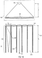
- FIG. 31 A further artificial illumination device presented in the aforementioned WO pamphlet is shown in Fig. 31 .
- a light source 990 and the chromatic diffuser 992 are totally separated and spaced apart from each other with the chromatic diffuser forming a window of a wall 994 of a house 996.
- shadows cast by the device of Fig. 31 show the typical radially symmetric outwardly pointing behavior resulting from an illumination using a single light source at a limited distance.
- an object of the present invention to provide an artificial illumination device for synthesizing natural light to illuminate an ambient as the actual sky and sun do, in particular by forming shadows that are parallel, sharp and more bluish than the rest of illuminated scene, and to make an observer experience an infinite visual depth perception of a sky and sun image when he/she directly looks at said artificial illumination device, without inter- and intra-conflicts among visual perception cues.
- the perception of natural illumination from sky and sun relies on the one side on the light emitted by the illumination device, which should feature a direct-light component highly collimated with low CCT, mimicking the light from the sun, and a higher CCT diffused-light component, mimicking the illumination effect of the sky, such that the direct-light component is able to cast sharp parallel shadows of the objects illuminated by the illumination device and the diffused-light component gives a bluish color to such shadows.
- the perception of natural illumination from sky and sun relies on the perception of infinite depth of the sky and sun images when directly viewing at the illumination device itself.
- the capability of an observer to evaluate the distance of objects, and therefore the depth of the views that constitute a three-dimensional scenery, is based on multiple physiological and psychological mechanisms connected to focusing, binocular disparity and convergence, motion parallax, luminance, size, contrast, aerial perspective, etc.
- Some mechanisms may gain significance compared to the others according to both the observing conditions (e.g, whether the observer is moving or still, watching with one or two eyes, etc.) as well as the characteristics of the scenery, these latter depending, for example, on whether objects with known size, distance or luminance are present, serving as a reference to evaluate how distant the observed element of the scenery is.
- these mechanisms hold both in the case of real images and of virtual images. More specifically, visual discomfort or eye strain may arise when conflicts exist between two or more different image planes simultaneously perceived at different depths by an observer because of one single visual perception cue, or two or more competing different high-level visual perception cues.
- the first image owing to the inherent transparency of the Rayleigh panel, is the real image of the LED array, the finite distance of which is supported in particular by accommodation and binocular convergence onto the LED array plane, and motion parallax.
- the second image is the virtual image of a bright spot surrounded by a bluish background, which is perceived at infinity.
- This second image is given by the fact that, as long as each LED 910 shines a circular symmetric light cone having divergence and orientation identical to those of all other LEDs, the group of LEDs 910 seen by each eye form a circular spot at the retina of the eyes of the observer.
- the LEDs 910 are seen under a cone with a fixed direction being given by the LED alignment direction which is, in the case of Fig. 29 , perpendicular to the panel 906, and with fixed angular aperture which coincides with the LED divergence cone angle.
- each of the observer's eyes sees its own group of illuminated LEDs 910 under the given direction and cone angle.
- This bright spot is perceived by binocular convergence at infinite distance, this being the setting which produces identical and equally centered images of such round spots on the retinas, as normal vision requires.
- the size of this bright spot depends on the angular divergence of the light emitted by each single LED element 910.
- the light source 902 does not contain any mechanism which prevents the first image plane, i.e. the plane of the real image of the array of LEDs 910, to be seen by an observer who directly looks at the light source 902, a visual perception conflict arises between the two above mentioned images perceived at different planes.
- This conflict which for example may be explained as an intra-conflict determined by binocular convergence, thus prevents the observer to perceive the appearance of natural sky and sun.
- such perception conflict makes the device in Fig. 29 unfit for solving the technical problem at the base of the present invention.
- the conflict arises because the observer sees the warm, direct-light component not only from the round bright spot, but also from the entire LED array.
- the background light produced by the LEDs at large angles is by far not uniform and follows the LED pitch periodicity.
- Such absence of uniformity is interpreted by the inventors as the main reason which makes the first image of the LED array at finite distance to prevail onto the second image of the bright spot at infinite distance, even in the case where the average luminance due to LED at large angle is much lower with respect to the bright spot, and even if it is weaker with respect to the uniform luminance of the diffused-light generator, too.
- the human eye is made to be very sensitive to luminance spatial gradients, and particularly to luminance spatial periodic modulations.
- the background light produced by the LEDs at large angles substantially spoils the color quality of the diffused light with respect, e.g., to the case of the embodiment described in Fig. 28 , in the sense that the resulting color differs substantially from the color of light from a clear sky.
- the minimum divergence achievable by commercial, dome-equipped LEDs is typically of the order of a few tens of degrees, i.e. a much larger figure than the 0.5° value featuring the actual sun beam divergence.
- This limit causes for the light source 902 an angle of penumbra by far larger than the natural one.
- the LED light-beam divergence may be reduced, e.g. to values as low as 6° to 7°, by using larger collimators, e.g. the commercially available TIR (total internal reflection) lenses, or CPC (compound parabolic concentrator) reflectors.
- This option does not help in supporting the perception of infinite depth, these large collimators leading to a very coarse pixelation which is even easier to be spotted by the eye than standard LED domes.
- a further problem of the light source 902 depicted in Fig. 29 detrimental in the visual appearance of the natural sky and sun is the perceivable pixelation of the bright spot, i.e. on the angle under which such bright spot is observed.
- highly collimated LEDs lead to lens (and thus pitch) sizes that are usually much larger than the standard dome, i.e. of about 1 cm or more, which causes the bright spot to be formed by very few pixels, i.e. LED/lens pairs, where the number decreases with the decrease in LED divergence both because of the lower cone angle under which the spot is observed and because of the increase of the lens size.
- the virtual image which corresponds to an infinite depth plane splits into two substantially different pixelated images which make the perception of the LED array plane to prevail over the infinite depth image. Such circumstance thus prevents an observer to spontaneously perceive an infinite depth for the sun image.
- the effect of the ambient light i.e. of the light which comes from the ambient lit by the illumination device or some other light sources and which, crossing the Rayleigh scattering panel 906 into upstream/reverse direction, lights again the LED 910 array, as well as the effect of the light which is reflected or diffused back by the Rayleigh panel 906 toward the LED array should be considered.
- This light which typically comes from all of the directions, i.e. is diffuse, provides an undesired contribution which further increases the visibility of the LED array.
- the device of Fig. 29 is not black even when it is switched off, as it happens when light feedback from the ambient does not play a role.
- the device of Fig. 29 fails in solving the technical problem at the base of the present invention because it fails in the requirement of visual appearance as the actual sky and sun when an observer directly views at the device itself, since it triggers visual perception cue conflicts between concurring visual planes, these planes being for example the real image of the LED 910 array and the virtual image of a bright spot corresponding to the sun. Moreover, it also fails in properly representing the image corresponding to the sun due to the large cone angle under which the bright spot is perceived and the clearly perceivable pixelation of such virtual image.
- Fig. 30 As a further example of the occurrence of conflicts among visual cues which prevent a device to produce a visual experience of infinite depth reference is made to the already mentioned embodiment depicted in Fig. 30 .
- the embodiment is optimized for maximizing the luminous efficiency by directing as much as possible of both direct and diffused light in the forward direction by means of the usage of a single optical element, instead of two, to perform both collimation and Rayleigh scattering.
- an antireflection coating and a reflecting chamber to redirect backscattered light in the forward direction are provided.
- no efforts are made in the device of Fig. 30 in order to generate a warm (e.g.
- the warm-light source 984 to be positioned at a focal distance from the lens 980.
- the source 984 is positioned much closer to lens, the goal being maximizing the amount of light collected by the lens and not that of generating parallel rays.
- the warm light exiting the circumferential portion of the lens is much weaker than the central one, due to the longer ray-path length from phosphor to lens and the larger inclination angle (each ray contribution to illuminance is proportional to the inverse of the square of said path length times the cosine of the incident angle).
- said difference may lead to warm-light luminance variation across the lens as a factor 8, which induces a strong spatial modulation in the luminosity of the Rayleigh diffuser. Unevenness is here further increased because the diffuser thickness decreases where the illuminance (from source 984) gets smaller.
- the device shown in Fig. 30 still suffers from several problems, including but not limited to visual cue conflicts, which prevent the observer from gaining a natural feeling about the artificial illumination.
- the small distance between the warm-light source 984 and the lens causes the source's virtual image to appear at finite distance, differently from what occurs for the natural image of the sun.
- the uneven illumination of the (lens) Rayleigh diffuser causes an uneven sky-luminance profile, which in turn forces visual cues to trigger the formation of the luminous-lens' real-image at the device plane, determining a cue conflict between said real and virtual image planes.
- the same close distance between source and lens leads the device in Fig.
- the reflector box 986 shines toward the observer several luminous contributions, i.e. light coming directly from the source 984, light reflected from the two lens-air interfaces, light back-scattered from the nanodiffusers as well as light coming from the illuminated scene downstream of the lens and crossing the lens in upstream direction.
- the reflector box further prevents any possible large depth visual experience, by creating an uneven and luminous background beyond the Rayleigh diffuser, at intermediate position between lens's and source's image planes.
- the reflector box 986 causes the color of the diffused light to depart from the actual color of sky light, thus spoiling the natural appearance of the sky and hindering possible positive effects related to the aerial perspective in deepening the perceived depth.
- the device of Fig. 30 fails in solving the technical problem at the base of the present invention because it fails both in the requirement of visual appearance as the actual sky and sun when an observer directly views at the device itself and in the requirement of illuminating an ambient as it is done by the sky and the sun.
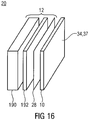
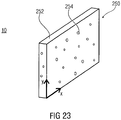
- a diffused-light generator 10 is positioned downstream relative to a direct-light source 12 composed of a 2-dimensional array of first light-emitting devices 14 with each first light-emitting device 14 having a collimator 16 associated therewith so as to collimate light output by the respective first light-emitting device 14.
- the diffused-light generator 10 may be a Rayleigh-like diffuser or may, as will be outlined in more detail below, alternatively or additionally comprise a diffused-light source which is at least partially transparent to the collimated light generated by direct-light source 12.
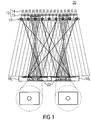
- Fig. 1 also illustrates the observer's eyes 18 L and 18 R looking into the direction of the artificial illumination device generally indicated with reference sign 20.
- the eyes 18 L and 18 R will naturally be set to infinity since due to binocular vision the observer will naturally try to have two sun images in the same position on the respective retina 22. Due to the diffused-light generator 10 being placed close to the plane of collimators 16, the eyes 18 L and 18 R will see a round sun in a blue sky environment.
- Fig. 1 concerns only the formation of the virtual image of the bright spot at infinite distance, while not considering the real image of the LED array which is formed by eye accommodation and convergence onto the LED array plane and contributes in preventing the device represented in Fig. 29 from guaranteeing a natural visual appearance of sky and sun.
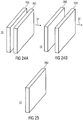
- Figure 2a illustrates an embodiment according to the present invention, which is capable of illuminating an ambient as the sun and the sky do through a window, and which guarantees at the same time a visual appearance of the illumination device that guarantees the experience of virtually infinite depth as the sky and the sun do in nature when they are observed through a window.
- the embodiment illustrates an artificial illumination device 20 for generating natural light as the sun and the sky, i.e. having a luminance profile and an appearance similar to that of the light from the sun and the sky.
- the artificial illumination device of Fig. 2a comprises a direct-light source.
- a first emitting surface 28 of the direct-light source is shown for sake of alleviating the understanding of Fig. 2 .
- the direct-light source comprises a first light-emitting device configured to emit primary light and positioned upstream relative to the light-emitting surface.
- the direct-light source 12 is configured to produce from the primary light a direct light 236 which exits the first emitting surface 28 with a luminance profile L direct (x, y, ⁇ , ⁇ ) which is uniform ( e.g. with respect to the spatial dependence) across the first emitting surface 28 and has a narrow peak 30 ( i.e.
- L direct (x, y, ⁇ , ⁇ ) has a peak subtended by a solid angle which is significantly smaller than 2 ⁇ sr, e.g. smaller than 0.4 sr, preferably smaller than 0.3 sr, more preferably smaller than 0.2 sr.
- the diffused-light generator 10 also not shown for illustration positioned downstream the first emitting surface 28.
- the diffused-light generator 10 comprises a second emitting surface 34 and an input surface 33 facing opposite to the second emitting surface, and is configured to be, at least partially, transparent to the light impinging onto the input surface 33.
- the diffused-light generator 10 is configured to emit a diffused light 35 from the second emitting surface 34, wherein said diffused light 35 is the component of the outer light which exist the second emitting surface 34 being scattered in virtually all forward directions and being uniform or at least weakly dependent on the spatial coordinates x,y.
- the diffused-light generator 10 is configured to emit a diffused light over a solid angle which is at least 4 times larger, preferably 9 times larger, more preferably 16 times larger than the solid angle subtending the narrow peak 30.
- the device of Fig. 2a is configured so that the direct light 236 produced by the direct-light source 12 has a CCT which is lower than a CCT of the diffused light 35 ( e.g. at least 1.2 times lower, preferably 1.3 times lower, more preferably 1.4 times lower).
- the diffused-light generator 10 is at least partially light-transparent, at least a portion of the direct light 236 propagates downstream the second emitting surface 34.
- the outer light comprises a first light component which propagates along directions contained within the narrow peak 30 (for example along at least 90% of the directions subtending the narrow peak 30, i.e.
- the first light component has a CCT which is lower than a CCT of the second light component ( e.g. at least 1.2 times lower, preferably 1.3 times lower, more preferably 1.4 times lower).
- the mutual positions of the first emitting surface 28 and the second emitting surface 34 are inverted with respect to the case of Fig. 2a .
- the second emitting surface 34 forms the outer surface 37 of the device 20
- the first emitting surface 28 forms the outer surface 37 of the device 20.
- the embodiment of Fig. 2b refers to an artificial illumination device which comprises a direct-light source (not shown), which in turn comprises a first light-emitting device 14 (not shown) configured to emit primary light (not shown) and a first emitting surface 28 positioned downstream the direct-light source, wherein said direct-light source 12 is configured to produce from the primary light a direct light 236 which exits the first emitting surface 28 with a luminance profile L direct (x, y, ⁇ , ⁇ ) which is uniform ( e.g. with respect to the spatial dependence) across the first emitting surface 28 and has a narrow peak 30 ( i.e. with respect to the angular dependence) along a direct light direction 32.
- a direct-light source not shown
- first light-emitting device 14 configured to emit primary light
- a first emitting surface 28 positioned downstream the direct-light source
- said direct-light source 12 is configured to produce from the primary light a direct light 236 which exits the first emitting surface 28 with a luminance
- 2b also comprises a diffused-light generator 10 (not shown) positioned downstream the first light-emitting device and upstream the first emitting surface 28 ( i.e. positioned inside the direct-light source 12) and configured to be, at least partially, transparent to the primary light, i.e. to the light impinging onto the input surface 33, and emit a diffused light 35 from a second emitting surface 34, wherein said diffused light 35 is the component of the light which exists the second emitting surface 34 being scattered in virtually all forward directions and being uniform or at least weakly dependent on the spatial coordinates x,y. Therefore, for the embodiment in Fig.
- the first emitting surface 28 is positioned downstream the second emitting surface 34, and the luminance profile L direct (x, y, ⁇ , ⁇ ) is the luminance at the first emitting surface 28 wherein the diffused-light generator 10 is physically removed from the system.
- the illumination device is configured so that the primary light 14 has a CCT which is lower than a CCT of the diffused light 35 ( e.g. at least 1.2 times lower, preferably 1.3 times lower, more preferably 1.4 times lower).
- the outer light at the first emitting surface 28 comprises a first light component which propagates along directions contained within the narrow peak 30 and a second light component which propagates along directions spaced apart from the narrow peak 30, wherein the first light component has a CCT which is lower than a CCT of the second light component.
- the embodiment comprises a dichroic optical element which assures both the functionalities of the diffused-light generator 10 and of the first emitting surface 28, as for example the functionality of generating a diffused-light component with CCT higher than the CCT of the primary light 14 and the functionality of collimating the complementary light component having CCT lower ( e.g. at least 1.2 times lower, preferably 1.3 times lower, more preferably 1.4 times lower) than the CCT of the primary light, respectively, as for the lens 980 in Fig, 30 .
- CCT lower e.g. at least 1.2 times lower, preferably 1.3 times lower, more preferably 1.4 times lower
- the property of generating a luminance profile L direct (x, y, ⁇ , ⁇ ) which is uniform ( e.g. with respect to the spatial dependence) and has a narrow peak 30 ( i.e. with respect to the angular dependence) along a direct light direction 32 should be attributed to the case of a direct-light source 12 which comprises an optical element identical to the dichroic optical element but without the functionality of the diffused-light generator.
- an embodiment is possible wherein the process of transforming the primary light into the direct light (e.g. the collimation process) is performed by a few optical elements positioned upstream of the first emitting surface 28, and wherein the diffused-light generator 10, positioned upstream of the first emitting surface 28, is neither directly lit by the primary nor by the direct light, but it is lit by an intermediate light evolving from the primary light and resulting in the direct-light at the first emitting surface 28.
- L direct (x, y, ⁇ , ⁇ )'s performances has to be verified with having physically removed the diffused-light generator from the illumination device.
- a further, more general, embodiment of the artificial illumination device assures all the features of the four embodiments of above and therefore it comprises:
- L direct (x, y, ⁇ , ⁇ ) (with respect to the spatial coordinates) is sufficient to avoid visual perception cue conflicts.
- the inventors noticed that a uniform luminance profiles cannot lead to a depth perception different from an infinite depth perception for any among the accommodation, binocular-convergence and motion parallax visual cues.
- the narrow peak 30 in the L direct (x, y, ⁇ , ⁇ ) angular profile plays a key role in the visual appearance of a prevailing infinite depth perception.
- a peak 30 in the angular profile of the spatially uniform L direct (x, y, ⁇ , ⁇ ) further improves an infinite depth perception.
- an observer's visual attention is preferentially attracted by the plane where the highest luminance, the highest contrast and the highest spatial frequency (provided that it is smaller than the frequency corresponding to the angular resolution limit) occur.
- the binocular convergence sets the eyes in order to avoid sharp and bright images to be differently positioned on the two retinas, with respect to correlated positions.
- the narrow peak in the L direct (x, y, ⁇ , ⁇ ) angular profile forces the two eyes to be aligned along parallel directions, supporting infinite depth perception of a bright spot representing the sun. Notably, this happens independently of the actual direction along which both the axes of the eye balls are aligned, i.e. even if the eyes are oriented so that the L direct peak creates a spot far from the center of eyes' retinas. In other words, the effect occurs as long as the bright and narrow spot is in the visual field, no matter if it is in the center or on a side.
- L direct L direct
- x, y, ⁇ , ⁇ L direct
- the spatial uniformity of L direct (x, y, ⁇ , ⁇ ) ensures also an infinite depth perception for the visual cue of motion parallax, since a moving observer experiences the virtual image due to any angular structure of L direct (x, y, ⁇ , ⁇ ), e.g the narrow peak 30 which represents the sun, as moving together with him/her as very far away objects appear to move in reality.
- the characteristics of the luminance profile in the embodiments above described result not to depend on the number of observers and their relative position with respect to the source, in the sense that each single observer experiences the same infinite depth perception coherently supported by visual perception cues.
- the luminance profile L direct (x, y, ⁇ , ⁇ ) of the light exiting the first emitting surface 28 of the direct-light source 12 therefore ensures the absence of intra- and inter- conflicts between visual depth perception cues, this being fundamental in order to induce a natural perception of infinity depth of both sun and sky.
- L direct (x, y, ⁇ , ⁇ ) of determining infinite depth perception typically increases with the increase of the contrast between peak and background in the luminance angular profile, i.e. a dark background strongly supports a prevailing infinite depth perception, in presence of a bright angular peak.
- a dark background further improves the prevailing infinite depth perception with respect to a brighter one since the lower the average luminance value of these non-uniform structures is with respect to the main narrow angular peak, the lower the visibility of possible non-uniformities in the background luminance profile is.
- a non-uniformity in a dark background determines much weaker visual perception cue conflicts than a non-uniformity of an intense background, for the same relative amplitude of fluctuations with respect to the average value of the background, where dark or intense are to be intended with respect to the luminance of the narrow angular peak 30.
- the narrow angular peak 30 along the direct-light direction 32 ensures parallel shadows with a sharp penumbra.
- the diffused-light generator 10 ensures on one side that the embodiment represented in Fig. 2 illuminates an ambient as the natural sky and sun, by providing a higher CCT diffused light component which tinges shadows in a bluish color as it happens for natural light entering an actual window. On the other side, the diffused-light generator 10 affects also the visual appearance of the device itself when directly looking at it. In fact, the diffused-light generator 10 creates a diffuse luminous bluish background around the low CCT bright spot determined by the luminance of the direct-light source.
- This luminous background instead of spoiling the infinite depth perception as it would happen for a white or a gray luminous background, further supports the infinite depth perception because of the synergistic action between the aerial perspective visual cue and the other visual cues, already described, supported by the direct-light source alone.
- the inventors notice the key role played by the three concurrent effects of the narrow peak in the L direct angular profile, of the spatial uniformity and smooth angular dependence of the diffused-light emitted from the second emitting surface 34 and of the high value of the diffused-light CCT (with respect to the direct light CCT).
- the spatial uniformity and smooth angular dependence of the diffused light alone would leave the perceived distance of the source of the diffused light as undetermined, i.e.
- the artificial illumination device 20 may be constructed so as to be "compact" in the sense defined herein below: considering the smallest volume Q encompassing the direct-light source 12, being T the length of the (cylindrical) projection of Q onto a line parallel to the direction 32 and being U the maximum distance between any two points on the first emitting surface 28, the direct-light source 12 is configured so that the width of the narrow peak 30 in the L direct angular profile is much smaller than arctan( U /2 / T ), i.e. 2 times, preferably 4 times, more preferably 6 times smaller than 2arctan( U /2 / T ), which means that by no means the narrow peak 30 can be obtained by simply positioning a light emitter far away from surface 28.
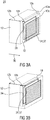
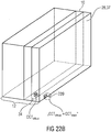
- the light illumination device is compact in the further sense that, as shown in Fig. 3a,b , the direct-light source 12 may be accommodated within a cuboid, the area of the ground face 12a of which is equal to or greater than the area of the light-emitting surface and the height 12b of which is smaller than a maximum width of the first emitting surface 28.
- the ground face 12a may comprise the first emitting surface 28 or may be placed parallel thereto with the first emitting surface 28 completely residing within the cuboid.
- the area of the first emitting surface 28 may be greater than 10 cm x 10 cm.
- the area of the ground face 12a may be smaller than 1.1 times the area of the first emitting surface 28.
- the aforementioned maximum width may be defined as the minimum distance between any two points of the first emitting surface 28.
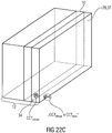
- the diffused-light generator 10 does not accommodate much space.
- the diffused-light generator 10 may be arranged within a cuboid having its ground face 10a in the same plane as the first emitting surface 28 and extending into the downstream direction 36 by a height 10b, as shown in Fig. 3a .
- the area of ground face 10a may be equal to or smaller than ground face 12a and the same applies to height 10b which may be smaller than or equal to height 12b.
- the top face 10c opposite to ground face 10a may comprise the second emitting surface 34 or the latter may be contained within the cuboid of the diffused-light generator 10.
- the area of the second emitting surface 34 is approximately equal to the area of the first emitting surface 28 such as, for example, +/- 10% of the area of the first emitting surface 28.
- the ground faces of the cuboids of generator 10 and source 12 may exceed the areas of the surfaces 34 and 28.
- the height 10b may be smaller than 10% of the aforementioned maximum width of first emitting surface 28 or smaller than 10 cm irrespective of the maximum of first emitting surface 28.
- the downstream direction 36 may, for example, be defined to point into the direction 32 into which the direct light generated by direct-light source 12 is emitted from the first emitting surface 28. As said, this direction 32 may be parallel to the normal of first emitting surface 28.
- Fig. 3b corresponds to the sequential arrangement between surfaces 28 and 34 of Fig. 2b .
- the cuboid of generator 10 may be completely contained within the direct-light source's cuboid.
- the direct-light source ability to produce the direct light such that same exits the first emitting surface 28 with a luminance profile L direct which is uniform across the first emitting surface 28 and has the narrow peak 30 around the direct-light direction 32, it follows that: 1) the direct-light direction 32 is substantially constant all over the first emitting surface 28, 2) the divergence is small, and 3) the divergence is substantially constant over all the first emitting surface 28.
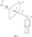
- small and substantially may be obeyed is explained in more detail herein below. In any case, with reference to Fig.
- the observer 38 sees, when looking towards the first emitting surface 28, a bright spot 40 which, when the observer moves relative to the light-emitting surface, moves relative to the first emitting surface 28 as if the bright spot 40 stemmed from an object positioned at infinity.
- the direct-light source 12 emits light with uniform intensity across the first emitting surface 28 at single, given direction 32 with respect to the emitting surface's normal z, with very low, preferably circular symmetric, divergence cone and low background outside such divergence cone, where both the divergence and the background are also uniform across the panel.
- L direct (x, y, ⁇ , ⁇ ) shall denote the luminance of the direct light as generated by the direct-light source at a dark environment, i.e. without any light originating or reflected from outside the direct-light source, where x, y, ⁇ and ⁇ are as defined before.
- the request on L direct is to show minimal spatial amplitude fluctuations for polar angle ⁇ greater than 3 ⁇ HWHM; e.g. the ratio between a standard deviation of said luminance spatial fluctuations and the luminance average value may not exceed the value of 0.3, preferably not exceed the value of 0.1, within any 10 mm diameter spatial circular areas and for at least 90% of the light-emitting surface, and may not exceed the value of 0.4, preferably not exceed the value of 0.3, more preferably not exceed the value of 0.2, within the entire at least 90% of the light-emitting surface, for any fixed azimuthal angle ⁇ and for any fixed polar angle ⁇ greater than 3 ⁇ HWHM ; as far as direct-light uniformity close to direction 32 is concerned, the request on L direct is of not exhibiting spatial fluctuations in a (local) polar angle leading to (local) maximum luminance with standard deviation larger than 20% of ⁇ HWHM within spatial areas of 5 cm diameter, preferably 10 cm
- the just mentioned constraints could be formulated as ⁇ x , y L direct x y
- L direct is fairly weak and uniform
- the observer 38 will see only a bright and round spot 40, with full-width angular size 42 equal to, or similar to, 2 ⁇ ⁇ HWHM , surrounded by a weak and uniform background.
- the direct-light source is configured to ensure dark and uniform background also when it is operated inside a fairly luminous environment, i.e. it is configured so that ambient light is not reflected or back scattered in an amount which may spoil the appearance of the first emitting surface 28 in terms of background luminance level and uniformity.
- the first emitting surface 28 not only emits but also may receive light from, for example, the diffused-light generator 10 (if positioned downstream of it) and/or from the ambient.
- the entire luminous flux generated by the direct-light source would return to the direct-light source itself.
- the direct-light source 12 is configured so that the first emitting surface 28 has a total reflectance (average) factor ⁇ r ⁇ 0.4, preferably n r ⁇ 0.2, more preferably ⁇ r ⁇ 0.1, even more preferably ⁇ r ⁇ 0.04, wherein the total reflectance factor ⁇ r is defined as the ratio of the luminous flux, reflected at all angles within the hemisphere bounded by the plane of the specimen, to the flux reflected from a perfect reflecting diffuser under the same geometric and spectral conditions of measurement, e.g. under diffuse illumination by a D65 standard illuminant which provides uniform illuminance (lux/m) onto the sample.
- a total reflectance (average) factor ⁇ r ⁇ 0.4 preferably n r ⁇ 0.2, more preferably ⁇ r ⁇ 0.1, even more preferably ⁇ r ⁇ 0.04, wherein the total reflectance factor ⁇ r is defined as the ratio of the luminous flux, reflected at all angles within the hemisphere
- the request on the dark and uniform appearance of the first emitting surface 28 far from direction 32 is even more stringent, since it is required that reflected light is always upper bounded by direct light both for what concerns the absolute luminance value and its fluctuations. More precisely, the embodiment ensures that the first emitting surface 28 preserves the same characteristics in terms of the background light also as a passive optical element, i.e. with respect to light that it reflects and diffuses when it is made to operate inside a fairly luminous environment. In other terms, the direct-light source 12 guarantees dark and uniform appearance for any polar angle of observation outside the emitting cone 30 also in the presence of strong ambient light.
- the direct-light source 12 should be configured such that, when the diffused-light generator 10 is removed from the artificial illumination device and the direct-light source 12 is off and the first emitting surface 28 is illuminated by an external diffused light which delivers onto the first emitting surface 28 a constant illuminance equal to the average of the illuminance delivered by the direct-light source 12 itself onto the first emitting surface when it is on, the external diffused light is reflected or back-scattered by the light-emitting surface producing a reflectance luminance profile L R at the first emitting surface 28 which is weaker than L direct at any position and any angle within at last 90% of the first emitting surface 28, and wherein L R exhibits an amplitude standard deviation within any 10 mm diameter spatial circular area that lower than the corresponding standard deviations of L direct within at last 90% of the first emitting surface 28.
- the constraints on the spatial fluctuations in the direction and the width of the narrow peak 30 of light generated by the direct-light source 12 at the first emitting surface 28 are formulated differently, namely the luminance profile L direct shows a range of a distribution of a local direction of a maximum value over the first emitting surface 28, of less than 2°, and the mean value over the first emitting surface 28 of a HWHM of a local average polar angle profile of L direct averaged over all azimuthal angles is below 5°.
- the distribution of the direction of the maximum value of the luminance profile should differ from a radially symmetric vector field so that shadows cast by objects in the direct light are not aligned along converging directions, as it would be the case in the device of Fig. 28 , Fig. 30 and Fig. 31 .
- the direct-light source is configured such that a plurality of elongated objects that are lit by the direct-light source and are oriented along direction 32 and parallel to each other cast onto an arbitrary plane a plurality of shadows that should not be featured by radially symmetric outwardly pointing behavior which is typical for illumination by a localized source at finite distance.
- the spatial fluctuations in the direction of the narrow peak 30, which may occur within the limitation of above, may be irregular or random.
- the artificial illumination device 20 provides a luminous, preferably bluish background that mimics the sky and stems from the diffused-light generator 10, while light caused by the direct-light source 12 which leads to the bright spot 40 is warmer in CCT.
- this spot 40 moves across it as the sun would across a real window.
- the observer 38 will perceive the bright spot 40 at infinite distance.
- the outlined features of the luminance profile L direct impose that the eyes are parallel in order to perceive equally positioned bright spots on the two retinas as depicted in Fig. 1 . This is the condition which guarantees the device 20 to provide large depth perception.
- L direct is independent from x, y and ⁇ and virtually null for ⁇ > ⁇ 0 and has a constant value for ⁇ ⁇ ⁇ 0 , where ⁇ 0 is, for example, 3° or more preferably 1° or even more preferably 0.5°.
- a background luminance of 10% of the maximum is a very high figure, which might, however, be acceptable in certain conditions such as conditions aimed at reproducing the sky and sun illumination at the very sunrise or sunset, i.e. when the luminance of the sun is not as high with respect to the luminance of the sky as during day time.
- the desired specifications can also not be achieved even if the LEDs of the setup of Fig. 29 would be coupled, e.g. with TIR optical concentrators, or more generally, by any among the standard concentrators used in the field of non-imaging optics such as, e.g. compound parabolic concentrators (CPCs) devices.
- CPCs compound parabolic concentrators
- the transverse size that these optical elements should have in order to ensure the desired low divergence is fairly large, namely several centimeters if one considers the minimum size of currently available general lighting LED chips of about 1 mm and the need of coupling most of the LED general light to the optics. This means that, at least close to the light-emitting surface, i.e.
- the observer's eyes will see the bright spot 40 inside each single optics, i.e. the spot size is smaller than the optics size such as, for example, the spot is roughly 2 cm at 1 m distance for 1° full divergence.
- the observer who looks at such low divergence non-imaging optics at a short distance from it cannot perceive a true image of any round spot, and moreover cannot experience any infinite focal depth, because the luminance generated by such non-imaging optics is neither truly uniform ( i.e. shift invariant) nor invariant with respect to the azimuthal angle.
- the two eyes will capture two images which (i) are in general not round, even if the emitting source, e.g. a LED, coupled to the optic is round and are not equal.
- the emitting source e.g. a LED
- the fact that the two eyes perceive different images is very detrimental with respect to what forces the two eyes to be set in parallel directions. Under this circumstance, it is much easier for the two eyes to focus on what, in contrast, is really seen as equal by both, i.e. the direct-light source object at finite distance. This spoils not only the roundness of the sun appearance, but also the infinite depth perception.
- the direct-light source 12 could be construed such that it comprises a 2-dimensional array of LEDs of special structure set out in more detail herein below with respect to Fig. 5 .
- each of LEDs 44 comprise a light emitter 46, such as a light emitting diode comprising phosphor and/or dye or the like and a collimator, e.g. a dome lens 48, wherein the dome is positioned at a distance 49 from the light emitter 46 substantially equal to the dome focal length.
- the light emitters 46 have a circular cross section in a plane perpendicular to direction 32, in order to facilitate the achievement of a luminance distribution independent of the azimuthal coordinate.
- domes 48 All internal surfaces of domes 48, but the windows 52 at the upstream side thereof through which the light emitters 46 emit their light, and the downstream ends thereof where the light collimating lens surfaces 54 are formed, are covered by a light absorber so as to form micro dark boxes as indicated at 56.
- surface 54 may be antireflection coated and the lateral dimension or width of the light emitting zones of the light emitters 46, i.e. 58, should be small enough so that the ratio between width 58 on the one hand and length 49 on the other hand is smaller than 1/10, preferably smaller than 1/20, most preferably smaller than 1/50.
- pitch 50 should be smaller than 3 mm, preferably 1 mm, most preferably 0.5 mm.
- the LEDs 44 may be packed closely such as in a hexagonal manner. The array of LEDs 44 would cover an area as wide as the first emitting surface 28.
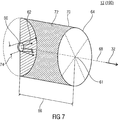
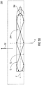
- Fig. 7 shows the direct-light source 12 as comprising a first light-emitting device 60 configured to emit primary light 62 and a collimator in the shape of a collimating lens 64 positioned downstream to, and at a focal distance 66 from, the first light-emitting device along an optical axis 68 which coincides with the direct-light direction 32.
- the lens 64 may be an imaging optical component, in the sense that the lens quality with respect to the given optical lay out parameters (i.e . the system numerical aperture, the distance between lens and emitting device, the ratio between focal length and transverse size of the emitting device, etc .) may be such as to ensure the lens to perform an image of the first light-emitting device 60 at infinity.
- the collimating lens 64 may be a Fresnel lens.
- the first light-emitting device 60 may be embodied as an LED.
- the optical axis 68 may coincide with the optical axis of the collimating lens 64 or may be oblique thereto with the optical axis 68 then being defined by a line connecting the intersection 61 between the collimating lens' 64 principal plane (in case of two principal planes, the one positioned nearer to the first light-emitting device 60) and the lens' 64 optical axis, with a barycenter of the first light-emitting device's 60 light emitting zone.
- the Fresnel lens 64 may be oriented in parallel to the first emitting surface 28 or may lie within the same as further outlined below. In case of other collimating lenses 64, the same may apply for the principal plane.
- the lens' 64 aperture covers an area as wide as the first emitting surface 28.
- the first light-emitting device 60 may have a circular aperture so as to result in a circular shape of the bright spot 40, in the observer's eyes focused at infinity.
- the direct-light source 12 of Fig. 7 may additionally comprise an absorber forming a dark box 70 housing the first light-emitting device 60 and having an aperture where the collimating lens 64 is positioned, wherein an internal surface 72 of the dark box 70 is formed by a light absorbing material having an absorption coefficient for visible light greater than 70%, preferably 90%, more preferably 95%. This results in obeying the reflectance luminance angular profile constraints.
- Fig. 7 is illustrative with respect to many features and could be varied accordingly.
- the collimating lens' 64 aperture does not need to be circular as depicted in Fig. 7 .
- it may be rectangular, hexagonal or have some other polygonal shape.
- the shape of the dark box 70 and its internal surface 72 it should be noted that same does not need to be cylindrical with a top face coinciding with the collimating lens' 64 aperture and the first light-emitting device 60 being integrated into an aperture of the bottom face of the cylinder or positioned within the cylinder. Any other shape may also be valid as long as any direct light paths between the first light-emitting device 60 and the collimating lens' 64 aperture is left unblocked.
- the internal surface 72 could extend between the cylinder shown in Fig. 7 and the frustum being non-concave, having minimum volume and extending between the light emitting zone of first light-emitting device 60 on the one hand and the aperture of the collimating lens 64 on the other hand.
- the ratio between the focal length 66 of collimating lens 64 on the one hand and the width 74 of the first light-emitting device's 60 aperture may be greater than 10 and preferably greater than 50.
- the focal length 66 may, for example, be greater than 10 cm and preferably greater than 20 cm.
- the area of the collimating lens' 64 aperture may, for example, be greater than 80 cm 2 and preferably greater than 300 cm 2 .
- the downstream face of collimating lens 64 may form the light-emitting surface.
- Figs. 5 to 7 may be combined for example with subsequently described embodiments for micro-optics beam-homogenizer layer so as to fulfill the constraints. Accordingly, embodiments of Figs. 5 to 7 may also form merely a part of the direct-light source 12, namely a collimated light source for generating pre-collimated light, e.g.
- a light beam with limited HWHM angular divergence for example with HWHM angular divergence smaller than 2.5°
- HWHM angular divergence smaller than 2.5°
- stray light at larger angles as for example stray light leading to secondary peaks or spikes in the light-beam angular profile.
- the configuration of Fig. 7 results in the angular divergence of the virtual image of the first light-emitting device 60 being smaller than the angular aperture with respect to the observer of the collimating lens 64, thereby ensuring that the image of the bright spot 40, i. e. the image of the first light-emitting device 60, appears as a luminous dot beyond the collimating lens' 64 aperture. That is, the image of the sun appears smaller than the aperture of lens 64 and the lens 64 itself is interpreted as a transparent window between the eye and the virtually distant object 40.
- An advantage of using a Fresnel lens as lens 64 is the technical possibility of achieving smaller output divergence angles.
- typical divergence angles of combinations of LEDs plus TIR lenses are of the order or larger than 8° to 10°.
- One of the main limits is due to the focal distance of the optical element, i.e. the TIR lens, which is of the order or less than 1 to 5 cm.
- the focal length of such a lens may be of the order of 20 to 30 cm, for example.
- the output angular divergence is thus given by the ratio between the spatial aperture 74 of the first light-emitting device 60 (including or not including a primary optics element, such as an LED dome) and the above mentioned focal length 66.
- the divergence is of the order or lower than 1°.
- a further advantage of the configuration of Fig. 7 is the absence of pixelation of the sun image.
- the output divergence is likely to be larger than the angular aperture of the LEDs' optics with respect to the final observer in the final setup for a viewing distance, for example, of the order of, or larger than, 1 m and an aperture of the primary optics, i.e. domes, of the order of 1 cm resulting in an angular aperture of 0.6° to be compared to the output divergence of 8° to 10°.
- Such a pixelation features an angular period definitely larger than the limit period for which the eye is not able to distinguish each single element. This fact along with the additional sensitivity of the eye to contrasts spoils the image effect of the infinite distance source by enabling the observer to actually see each single lens element of the structure of Fig. 29 . This does not happen in the case of Fig. 7 .
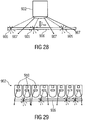
- pairs of first light-emitting devices 60 and lenses 64 may be combined together and positioned in juxtaposition so that the collimating lenses 64 of the pairs abut each other so as to form a joined continuous surface. If the collimating lenses 64 are formed as Fresnel lenses as illustrated in Fig. 8 by circular lines within one of the lenses 64, then the array of Fresnel lenses may be easily formed by one continuous monolithic object such as plastic or glass. As in the case of Fig. 6 , the pairs of first light-emitting devices 60 and collimating lenses 64 may be packed together along the 2-dimensional array of pairs in a hexagonal manner. Accordingly, the apertures of the individual collimating lenses 64 may be formed hexagonally.
- the optical axis 68 of the individual pairs of device 60 and lens 64 can be arranged to extend parallel to each other and the direct-light direction 32, respectively.
- the downstream face of lenses 64 could form the first emitting surface 28 or have, at least, an area being as great as the surface 28.
- the direct-light source 12 comprises a 2-dimensional array of first light-emitting devices 60 which, as described above with respect to Fig. 7 , may comprise a circular aperture in order to provide for a circular appearance of spot 40, a 2-dimensional array of collimating lenses 64, which are advantageously formed as Fresnel lenses, wherein the two arrays are registered to each other so that the optical axes 68 are parallel to each other and parallel to the direct-light direction 32.
- a 2-dimensional array of first light-emitting devices 60 which, as described above with respect to Fig. 7 , may comprise a circular aperture in order to provide for a circular appearance of spot 40, a 2-dimensional array of collimating lenses 64, which are advantageously formed as Fresnel lenses, wherein the two arrays are registered to each other so that the optical axes 68 are parallel to each other and parallel to the direct-light direction 32.
- the array of lenses and the array of first light-emitting devices may be displaced relative to each other such that the optical axes of the lenses 64 are offset from the positions of the first light-emitting devices so as to result in a direct-light direction 32 which is oblique relative to the plane within which the apertures of lenses 64 are positioned and distributed, respectively.
- each collimating lens 64 is placed at a distance from the first light-emitting device 60, which corresponds to, or is of the order of, the focal length of the collimating lenses 64, it is possible to achieve the low divergence constraint previously formulated. Since each collimating lens 64 is coupled to a single associated first light-emitting device, the first light-emitting device pitch is sizably increased relative to the configuration in accordance with Fig. 29 , which means that higher luminous flux per first light-emitting device 60 is needed in order to have the same lumen per unit area.
- the collimating lenses 64 make with the eye lens of the observer a telescope which forms the first light-emitting device and its aperture, respectively, onto the retina. This is the reason why each first light-emitting device should have a circular aperture in order to form a circular image in the observer's eye, i.e. form the roundness of spot 40.
- the embodiments for direct-light source 12 showed the actual light emitting zone to be positioned downstream relative to some collimating lens along an optical axis coinciding with a direct-light direction.
- the direct-light source 12 may comprise an edge-illuminated lightguide emitter panel comprising a wave guiding panel, operated via total internal reflection, one or more light source(s) coupled to an edge of the wave guiding panel, and a plurality of micro-optical elements such as microprisms, microlenses, etc. which contribute in extracting the light from the wave guiding panel into the direct-light direction.
- the embodiments of Figs. 5 to 8 could be called “back-illuminated emitters”
- the embodiments further outlined with respect to the following figures are termed "edge-illuminated lightguide emitter panels”.
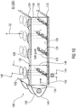
- Fig. 9 shows an embodiment for an edge-illuminated lightguide emitter panel as an example for the direct-light source 12 according to which same comprises a wedge-shaped lightguide layer 80 sandwiched between an absorber shaped as a light absorbing layer 82 and a light exit layer 84 so that the wedge-shaped lightguide layer guides light by total internal reflection and so that the light absorbing layer 82 is positioned upstream relative to the wedge shaped layer 80 and the light exit layer 84 is positioned downstream relative to the wedge shaped lightguide layer 80, wherein n 3 ⁇ n 2 ⁇ n 1 with n 1 being the refractive index of the wedge shaped lightguide layer 80, and n 2 being the refractive index of the light exit layer 84 and n 3 being the refractive index of the light absorbing layer 82.
- layers 80 and 84 may be made of glass or transparent plastics, while several possibilities exist to realize the light absorbing layer 82.
- the wedge-shaped layer 80 may feature a wedge-slope below 1 degree.
- the light absorbing layer 82 may actually be a light absorbing panel 88 separated from the wedge shaped lightguide layer 80 via a gap 90 filled, for example, with air, vacuum or another low refractive index material, the refractive index of which is denoted by n 3 .
- Another possibility would be to form the light absorbing layer 82 by some coating, the coating being composed of material having the refractive index n 3 small enough in order to be lower than n 1 and n 2 , concurrently.
- the light-absorbing layer 82 may absorb at least 70%, preferably 90%, most preferably 95% of the visible light which impinges on the light-absorbing layer 82.
- the light exit layer 84 comprises a plurality of micro-reflectors 94 at an interface 96 between the light exit layer 84 and the wedge shaped lightguide layer 80 so as to redirect light rays 98 having crossed the interface 96 between the wedge shaped lightguide layer 80 and the light exit layer 84 and propagating at an angle with respect to a normal to an upper (or external) surface 118 of the exit layer which is lower than a limit angle for total internal reflection at said upper surface, wherein said upper surface is a surface of the exit layer facing away from the wedge layer, so that the light reflected by the micro-reflectors propagates out of the light-exit layer into the direct light direction 32.
- Fig. 9 exemplarily shows a light ray propagating by internal reflection through the wedge shaped lightguide layer 80 along a guiding direction 106, i.e. the direction of gradient along which the wedge shaped lightguide layer 80 gets thinner, which intersects the interface 96 at a point 97 where the angle of the light ray with respect to the normal to the interface 96 is slightly less than the limit angle for total internal reflection. This allows a portion of the light to cross interface 96 and to propagate further at a small angle relative to interface 96 along guiding direction 106, such as ray 98.
- the micro-reflectors 94 protrude from the interface 96 away from wedge shaped lightguide layer 80 and have reflective surfaces 102 oriented such that reflection of ray 98 points, after refraction from the upper surface 118, into the direct-light direction 32. Accordingly, as shown in at 104, the micro-reflectors 94 may be formed translatory invariant or longitudinally along a direction 99 laying in the plane of interface 96 and perpendicular to the direction of gradient 106, with their face 102 facing upstream relative to this guiding direction 106 being oriented for example at approximately 40° to 50° relative to interface 96 in order to achieve a direct-light direction 32 nearby the normal direction of interface 96.
- the micro-reflectors may, for example, be formed as grooves or voids in the material of the light exit layer 84, at the face of this layer 84 forming the interface 96 with the wedge shaped lightguide layer 80.
- the edge illuminated lightguide emitter panel of Fig. 9 comprises a three-layer structure (TLS).
- the central layer 80 has a wedge shape and is made of a transparent material of refractive index n 1 .
- the bottom layer has refractive index n 3 ⁇ n 1 and is made to absorb visible light which eventually enters the TLS structure from the upper surface 118 of layer 84, e.g. ambient light or light backscattered by the diffused-light generator 10.
- the upper layer 84 is transparent, has refractive index n 2 fulfilling n 3 ⁇ n 2 ⁇ n 1 and comprises micro-optical elements such as void microprisms for extraction of the light out of the TLS.
- the direct-light source 12 of Fig. 9 further comprises an edge illuminator 108 configured to couple light into the wedge shaped lightguide layer 80 from an edge 110 thereof into the guiding direction 106.
- the edge illuminator 108 comprises a light concentrator 112 such as a reflective concentrator and a first light-emitting device in the shape of light source 114.
- the combination of the concentrator 112 and the light source 114 generates light collimated in a first plane determined by directions 106 and 99 and in a second plane containing guiding direction 106 and the normal to surface 118.
- the collimation in the first plane may be stronger than the one in the second plane.
- Such a concentrating device may be shaped for example as a rectangular compound parabolic concentrator (CPC), as depicted in Fig. 9 , which comprises a rectangular input aperture IN that is coupled to the LED source and a rectangular output aperture OUT that faces the input facet of the lightguide 110 and comprises four parabolic mirror surfaces each of which is one-dimensionally curved and has a generator parabola lying either in the first or in the second plane, and with all the generating parabolas having their focus in the plane of the input aperture IN.
- the input aperture IN is shaped as a thin rectangle elongated along the normal to the first plane.
- Light source 114 may be formed by a 1-dimensional array of first light-emitting devices 111 such as LEDs and the same applies for concentrator 112 in the sense that a 1-dimensional array 109 of pairs of first light-emitting devices 111 and light concentrators 113 such as reflective ones, could be used as edge illuminator 108.
- the collimation in the first plane being stronger than in the second plane is useful for guaranteeing the beam exiting the surface 118 to feature similar divergence in a third plane, containing the directions 32 and 106, and in a fourth plane, containing the directions 32 and 99.
- the light extraction mechanism here described may perform a substantial reduction of the beam divergence in the plane of incidence of light rays onto the interface 96, but not in orthogonal planes.
- the combination of layers 80 and 84 behaves as a collimator, which reduces the beam divergence in said plane of incidence of light rays onto the interface 96, and therefore further contributes to the action of the collimating optics 112 to minimize the divergence of the output beam.
- the collimating optics 112 couples the light generated by the primary source 114, such as white light, into the wedge shaped lightguide layer 80, the light rays 100 strike and are initially reflected by total internal reflection by the lower surface 116 of layer 80 facing the light absorbing layer 82 and interface 96 facing layer 84.
- n 1 /n 2 should be chosen large enough to guarantee the coupling for the chosen input light divergence as determined by the combination of primary source 114 and concentrator 112.
- the light beam divergence increases with propagation inside the lightguide layer 80 along propagation guiding direction 106, leading to continuous leakage from layer 80 to layer 84 when crossing interface 96.
- no leakage occurs at the interface between the central and the bottom zone, namely if n 1 /n 2 ⁇ n 1 /n 3 .
- the light that has crossed the interface 96 between layer 80 and layer 84 propagates in the light exit layer 84 almost parallel to interface 96, i.e.
- a small grazing angle which is, for example, lower than 5° with respect to interface 96.
- This light could hit the upper surface 118 of layer 84 facing away from layer 80, experience total internal reflection and then cross the interface 96 between layer 80 and layer 84 again.
- light 98 hits one of the micro reflectors 94, thereby being reflected outside the TLS into direction 32.
- the reflective surface facet of the micro reflectors 84 pointing into the direction of edge illuminator 108 are oriented such that the normal direction of these reflection surfaces 102 are angled relative to the interface 96 at an angle relative to interface 96 corresponding to half the angle which direction 32 encloses with interface 96, plus the aforementioned grazing angle of rays 98.
- the angle has to be chosen according to the desired output angle direction 32.
- the micro reflectors 84 may be formed as microprisms, and in particular these prisms may be made as void prisms as already outlined above and illustrated at 104. Those void prisms would reflect the light via total internal reflection.
- the micro reflectors may be mirror coated indentations of the light exit layer 84. All micro-reflectors 94 may be arranged in parallel to each other and may have the same apex angle in order to achieve a constant output direction 32.
- the size and the number per unit area of the micro-reflectors 94 may change across the TSL, i.e. along the guiding direction 106, in order to optimize the luminance uniformity, i.e. in order to obey the above outlined luminance uniformity request.
- the divergence of the light beam exiting the surface 118 in the third plane decreases with decreasing input divergence of the edge illuminator 108 in the second plane on the one hand and the wedge slope on the other hand.
- the output divergence of the light exiting the TLS in direction 32 in the just mentioned third plane is about 2.25° HWHM.
- 1.001 ⁇ n 1 /n 2 ⁇ 1.1 may hold true, for example.
- the output divergence in the orthogonal plane i.e.
- the output divergences in the two just mentioned orthogonal planes are independent from each other, and the output angular spectrum or luminance angular profile L direct would likely show a rectangular peak into direction 32.
- a square spectrum could be obtained by suitably choosing the ratio between the input divergence in the first and second plane.
- the desired roundness in the light source image appearance i. e. a round appearance of spot 40, may be achieved by adding a low-angle white-light diffuser such as a "Lee filter 253 Hampshire Forst", or a "Lee filter 750 Durham Frost" downstream the TLS shown in Fig. 9 , as it is described herein below.
- a low-angle white-light diffuser is a diffuser which operates by performing the convolution of the angular spectrum of the impinging light with a given response function, which is here taken symmetric around a certain direction (e.g. a normal to a surface of the low-angle white-light diffuser) and having a HWHM divergence less than 10°, preferably less than 5°, more preferably less than 2°.
- a solution alternative to the usage of the edge illuminator 108 for the purpose of obtaining a collimation in the first plane stronger than in the second plane may be also obtained by using an array of LEDs similar to those described in Fig. 6 but configured in such a way to deliver two different divergence values in two orthogonal planes containing direction 49.
- HWHM divergence of 2.25° and 20° in the two planes may be obtained using rectangular LED emitters 46 of size 0.31 ⁇ 2.8mm 2 and a lens dome with focal length 49 of about 4mm.
- the light absorbing layer 82 of the TLS is light absorbing ensures the black appearance of the direct-light source 12 when the same is off, thereby fulfilling the above outlined constraints regarding the reflectance luminance profile, i.e. the low luminance value outside the emission cone.
- the light absorbing layer's interface to layer 80 behaves as a mirror only for the light guided inside the lightguide layer 80, but is virtually transparent for the light coming from outside the TLS, i.e. such as the aforementioned diffused light entering the light-emitting surface of the direct-light source 12 from outside. Such light is then for example absorbed by the light absorbing panel 88.
- Fig. 10 shows another example for an implementation of the direct-light source 12 in the form of an edge illuminated lightguide emitter.
- the edge illuminated lightguide emitter panel comprises a light guide layer 120 sandwiched between an absorber shaped as a light absorbing layer 122 and a light exit layer 124 so that the light absorbing layer 122 is positioned upstream relative to light guide layer 120 and the light exit layer 124 is positioned downstream relative to the light guide layer 120.
- layers 120, 122 and 124 reference is made to the description of Fig. 9 .
- n 3 ⁇ n 1 and n 2 ⁇ n 1 is sufficient with n 1 being the refractive index of the light guide layer 120, n 2 being the refractive index of the light exit layer 124, and n 3 being the refractive index of the light absorbing layer 122, which may comprise a transparent gap as described for the layer 82 of Fig. 9 .
- the light guide layer 120 comprises a plurality of micro-reflectors 126 at an interface 128 between the light absorbing layer 122 and the light guide layer 120 so as to redirect light internally guided within the light guide layer 120 toward the light exit layer 124 at an angle with respect to the normal to the interface 134 between layer 120 and 124 which is smaller than the limit angle for total internal reflection for the light guided within layer 120.
- Each micro-reflector 126 is positioned at a focal point of a respective lens 130 formed on an outer surface 132 of the light exit layer 124 facing away from the light guide layer 120.
- the combination of the micro-reflector 126 and lens 130 arrays thus constitutes a collimator to reduce the divergence of the output light.
- the configuration of the edge illuminated lightguide emitter panel of Fig. 10 is based on a rectangular light guide layer 120, i.e. the light guide layer 120 has parallel interfaces to layers 122 and 124, respectively, namely interface 128 to light absorbing layer 122, and interface 134 to light exit layer 124.
- the micro-reflectors 126 and the collimating lens formed at the outer surface of the light exit layer 124 are 2-dimensionally distributed along the interface 128 and the outer surface 132, respectively, and registered to each other so that the optical axis 135 extending through each micro-reflector 126 and the respective collimating lens 130 are parallel to each other and the direct-light direction 32, respectively.
- an edge illuminator 108 couples light into an edge 136 of the light guide layer 120, wherein as shown in Fig. 10 this edge illuminator 108 may also be composed of a 1-dimensional array of pairs of a first light-emitting device 138 and corresponding concentrator 140 extending 1-dimensionally along the edge 136 just as illustrated in Fig. 9 .
- each micro-reflector 126 faces a corresponding one of the collimating lenses 130, both being positioned at a focal distance from each other.
- the micro-reflectors 126 have an elliptic mirror face oriented so as to mirror light coupled into the light guide layer 120 along a central propagation direction 142 ( i.e. the direction along which the lightguide is illuminated), into the direction 32, i.e. along optical axis 135.
- the shape of the micro-reflectors 126 may be that of a cylinder protruding from interface 128 and being cut at the just mentioned mirror angle, i.e. the angle necessary in order to lead to a circular cross section when projected onto a plane orthogonal to direction 32.
- the size of the lenses 130 is determined by the need of capturing the light reflected by the micro-reflectors. For example, it can be taken 1.5 times the product between the focal length 146 and 2 times the tangent of the internal lightguide mode half divergence, which means a lens diameter 148 of the order of one half of the focal length for a lightguide coupling 2x10° internal divergence mode.
- the lateral distribution or density of the 2-dimensional distribution of the reflector/lens-coupler pairs should be tailored in order to maximize luminance uniformity, averaged over an area of few-lens diameter.
- the lenses 130 may be formed on the material of layer 124 featuring a flat interface 134 with the lightguide layer 120 and a lower refractive index. In doing so, the lenses 130 do not interfere with the lightguide 120 and operate only on that light which is reflected by the micro-reflectors 126 so as to exit the first emitting surface 28 in direction 32.
- Fig. 11 briefly shows another possibility of forming the direct-light source 12.
- a primary light source such as a combination of a first light-emitting device comprising a light emitter and a concentrator, indicated at 150 in Fig. 11 , lights the first emitting surface 28 of the direct-light source via a mirror system 156 which, exemplarily, merely consist of one mirror 152 in the case of Fig. 11 .
- Light source 150 and mirror system 156 are arranged such that the light beam 154 generated by light source 150 is collimated by the mirror system 156 and, thus collimated, impinges onto a rear face of the first emitting surface 28 so as to exit the first emitting surface 28 with a luminance angular profile L direct obeying any of the above mentioned constraints into the direct-light direction 32.
- the mirror system 156 comprises, for example, a concavely curved mirror such as mirror 152.
- the primary light source 150 is placed at a focal plane of mirror system 156, which in turn acts as a collimator for light exiting the primary light source 150, and images primary light source's 150 aperture into infinity along direction 32 through first emitting surface 28.
- light source 150 and mirror system 150 are housed within an absorber shaped as a dark box 158 fully covered by light absorbing material along the dark box's internal surface and comprising a window forming the first emitting surface 28.
- the mirror system 150 is configured such that no light beam emanating from first emitting surface 28 into the inner of dark box 158, which hits that mirror 152 of mirror system 156, which is positioned most downstream along the optical, bended light path 160 leading from light source 150 to first emitting surface 28, is reflected by this mirror system 156 back to first emitting surface 28.
- Some of the embodiments for the direct-light source outlined above may suffer from strong spatial luminance modulation over the first emitting surface 28.
- the light illuminance over each collimating lens 64 is featured by such spatial modulation being, for example, a few times more intense at the center of the lens aperture than at the border of each lens 64.
- the just mentioned illuminance periodic modulation of the collimating lens 64 automatically translates into a periodic luminance modulation of the high CCT background of diffused light generated by the diffused-light generator 10 owing to the very high visual sensitivity to periodic luminance modulation. Such effect is detrimental with respect to the quality of the natural illumination.
- a first solution to this problem is that of adding downstream to the outer emitting surface 37 a coffered ceiling structure, this structure having the same pitch, for example, as the collimating lenses 64 in case of the embodiment of Fig. 8 or having a pitch which is an integer multiple or a unit fraction of the pitch of collimating lenses 64.
- the coffered ceiling structure comprises a network of cells, which are formed by void volumes separated by walls, wherein said walls have negligible total transmittance and wherein said cells have an input facet F_IN lying in a plane parallel to the plane of outer emitting surface 37 and an output facet F_OUT, and wherein F_IN and F_OUT may or may not have the same shape and the barycenter of F_OUT may be offset relative to the projection of the barycenter of F_IN onto F_OUT along the direction 32 and each cell faces a lens 64, in the sense that F_IN is inscribed in the projection of the lens 64 or lens' 64 aperture onto the plane containing F_IN along the direction 32.
- Fig. 12 which shows such a coffered ceiling structure 170 positioned downstream to the diffused-light generator 10 which is, exemplarily, embodied as a Rayleigh diffuser panel with regard to which further details are described below using the direct-light source 12 of Fig. 8 .
- the coffered ceiling structure 170 has a first periodicity 172 being identical to the periodicity 174 at which the collimating lenses 64 and their corresponding first light-emitting devices (not shown in Fig. 12 ) are distributed along the emitting surface 28 which extends between diffused-light generator 10 and the plane of the collimating lenses 64 in the case of Fig. 12 .
- first periodicity 172 being identical to the periodicity 174 at which the collimating lenses 64 and their corresponding first light-emitting devices (not shown in Fig. 12 ) are distributed along the emitting surface 28 which extends between diffused-light generator 10 and the plane of the collimating lenses 64 in the case of Fig. 12 .
- the diffused-light generator 10 is positioned downstream of the first emitting surface 28 and thus constitutes the outer emitting surface 37.
- the presence of the coffered ceiling structure 170 is not to be intended as limited to this case, but it applies also to the case in which the first emitting surface 28 is positioned downstream of the diffused-light generator 10, and constitutes the outer emitting surface 37, or to the case in which the first emitting surface 28 and the second emitting surface 34 of the diffused-light generator 10 coincide to form the outer emitting surface 37.
- the direct-light direction 32 could be taken into account to increase the effect of distracting the observer from realizing the illuminance periodicity originating from the illuminance modulation of the collimating lenses 64.
- the walls or side surfaces of the coffered ceiling structure 170 could be oriented perpendicular to the outer emitting surface 37, while the direct-light direction 32 is tilted or oblique with respect to a direction parallel to the normal of the outer emitting surface 37. More generally, the direct-light direction 32 is tilted or oblique with respect to more than 90% of the outer surface of the coffered ceiling structure.
- the coffered ceiling structure's outer surface could be oriented such that in a projection along the direct-light direction 32 at least 30% of the outer surface of the coffered ceiling structure 170 is facing and at least 30% of the outer surface of the coffered ceiling structure 170 is averted.
- the latter circumstance would even be possible by arranging the direct-light direction 32 to be parallel to the normal direction of the light-emitting surface.
- Fig. 12 shows the coffered ceiling structure in connection with the embodiment for the direct-light source 12 in accordance with Fig. 8
- the coffered ceiling structure is combinable with any embodiment of the direct-light source 12 including those described next.
- periodicities such as periodicity 174 may also occur with other embodiments for the direct-light source and accordingly, the periodicity dependency could also be optionally applied to such other embodiments.
- the periodicity dependency could be selected such that the periodicity 172 is an integer multiple or a unit fraction of periodicity 174.
- Figure 13 refers to the embodiment depicted in Fig. 12 , in which the second emitting surface 34 of the diffused-light generator constitutes the outer emitting surface 37.
- the diffused-light generator 10 is again assumed to be a Rayleigh-like diffuser as will be outlined in more detail below.
- the coffered ceiling structure 170 overcomes the problem of intensity modulation of the artificial sky due to non-uniform illumination of the collimating lenses 64.
- a non-uniform illumination determines a non-uniform output light intensity along the spatial dimension of the lenses 64 themselves.
- non-uniform light impinging on the diffuser panel 10 determines a series of brighter and darker areas in the blue diffused light, i.e. brighter and darker zones in the "sky".
- the array of collimating lenses (in the exemplary case of Fig. 8 ) plus diffuser panel determines a periodicity of such intensity modulations, which is easily spotted by the eye of the observer.
- the coffered ceiling structure 170 consists of a series of barriers extending between the individual zones of diffuser panel 10 (the second emitting surface 34 of which constitutes in this case the outer emitting surface 37) overlapping the individual lenses 64, and elongate outside the outer emitting surface 37, i.e. protrude therefrom.
- the direction of the collimated direct light component with lower CCT originating from the artificial sun i.e. direction 32
- such direct light component can illuminate only one half of the side faces of the barrier structure 170.
- an observer When looking at the ceiling, an observer will see the sky and part of each barrier 170. In particular, the observer will see between each high CCT zone of sky illumination either a part of the barrier 170 lit by direct illumination and thus with lower CCT, which may be called “white” barriers, or a part of the barrier falling into the shadow zone (thus partially illuminated by the diffused high CCT component, which may be called “dark” barriers).
- the luminance of the barrier will be very different from the average luminance of the sky, much higher for the "white” case and much lower for the "dark” case.
- This alternation between sky zones and barriers with very different luminance helps in masking the modulation of the artificial sky, since the sky-to-"white” or sky-to-"dark” modulation is much stronger than the internal modulations of the sky itself, which stem from the unintended illumination modulations illustrated above.
- Such sky modulation then appears highly attenuated.
- the coffered ceiling structure 170 will then appear as a "white” and "dark" grid between the observer and an apparently uniform sky.
- Figs. 12 and 13 it should be mentioned that the term "coffered ceiling structure" as used herein so far should not be understood to restrict these embodiments to cases where the light-emitting surface is arranged horizontally to form, for example, an artificial illumination device on the ceiling of a room. Rather, the term shall merely be understood to structurally describe the structure 170.
- the coffered ceiling structure 170 is advantageous not only with respect to combinations of the direct-light source 12 with a Rayleigh-diffuser as the diffused-light generator 10, but also with respect to other embodiments where the diffused-light generator 10 is composed of a diffused-light source, embodiments for which are described in more detail below.
- the structure 170 is also combinable with any other source 12, and also in the cases in which the diffused-light generator 10 is positioned upstream relative to the first emitting surface 28., provided that the structure 170 is positioned downstream of the outer emitting surface 37.
- the problem just described namely the problem regarding the non-constant illumination across the collimating lens' aperture
- primary lenses such as freeform lenses
- the freeform lens is configured to flatten the illuminance distribution of the primary light onto the collimating lens.
- Fig. 14a shows a freeform lens 180 positioned between the first light-emitting device 60 and its collimating lens 64 along optical axis 68.
- freeform lenses 180 may also be used in the embodiment of Fig. 8 with respect to each pair of first light-emitting device 60 and collimating lens 64.
- Fig. 15 The requirement of uniform illumination improves the final perception of the artificial illumination device by means of a uniform sky appearance as already described above with respect to Figs. 12 and 13 .
- the illumination distribution over the input surface (aperture) of lens 64 is in general nonhomogeneous.
- a further requirement for the light distribution at the input surface of the lens 64 is that the illuminance rapidly decreases outside the area of the aperture of lens 64.
- a second important point is the visual appearance of the source 60 in the observer's eye. Since a circular image of the artificial "sun” shall be obtained, a circular appearance of the first light-emitting device 60 is needed. Freeform lenses could achieve one or possibly most of the previous requirements. In particular, the requirement of uniform illumination may be tackled by using an optical element which redirects light propagating around the axial direction with low propagation angle towards the outer region of emission, as shown on the left hand side of Fig. 15 .
- the freeform lens 180 features a circular shape in order to facilitate the visual appearance of a round source of light when the freeform lens 180 is imaged by the eye of the observer through the lens 64.
- Fig. 14b shows the alternative of using such a reflective CPC 182 in front of, i.e. downstream, the first light-emitting device 60.
- the width 74 of the first light-emitting device 60 and distance 66 between first light-emitting device 60 and lens 64 are corrected in order to account for the differences in construction, due to the presence of the freeform lens 180 or CPC 182.
- Figs. 14a , b and 15 are also combinable with the embodiment of Fig. 8 .
- the embodiments of Figs. 14a , b and 15 are also combinable with the embodiments of Figs. 12 and 13 .
- the embodiments for the direct-light source 12 provided so far may in some cases exhibit minor problems in achieving the above identified luminance angular profile constraints due to, for example, scattering problems or the like.
- these problems are addressed by using any of the above outlined embodiments for the direct-light source 12, namely the ones described with respect to Figs.
- the micro-optics beam-homogenizer layer 192 thus positioned is able to transform a first collimated beam featured by the presence of stray light that impinges onto said homogenizer layer 192 from the collimated light source 190 into a second collimated beam with divergence equal to or larger than the divergence of the first collimated beam and which is free from stray light.
- Such second collimated beam thus exit the first emitting surface 28 towards the diffused-light generator 10 as depicted in Fig. 16 .
- the first emitting surface 28 is positioned downstream of or coincides with the second emitting surface 34 of the diffused-light generator 10, thus this second collimated beam exiting the beam-homogenizer layer 192 impinges onto the diffused-light generator 10 towards the first emitting surface 28.
- Stray light as just described may for example stem from non-ideal behavior of some Fresnel lenses in the case of using Fresnel lenses in order to embody the collimating lens 64.
- the Fresnel lens 64 lit by the first light-emitting device 60 may have a luminance profile which does not go to zero out of the narrow peak 30.
- it may be featured by a residual profile, which is also structured both in angle and in position, which finally might make the Fresnel lenses 64 a clearly visible and luminous object in embodiments of Figs. 7 and 8 , where in contrast a complete dark or uniform background would be needed. Problems like this may also occur with respect to the other embodiments for the direct-light source and collimated light source 190, respectively, described so far.
- a micro-optics beam-homogenizer layer 192 may be used, for which specific embodiments are described further below.
- FIG. 17a-c shows exemplarily a combination of a light emitter and a collimator such as a first light-emitting device 60 and a Fresnel lens 64 as an example for the collimated light source 190, but as already stated in the preceding paragraph, the beam-homogenizer layer 192 exemplified in Fig. 17a-c is combinable with any of the embodiments for the direct-light source 12 described so far above in order to result in further embodiments for the direct-light source 12 comprising a combination of collimated light source 190 and beam-homogenizer layer 192.
- the micro-optics beam-homogenizer layer 192 of Fig. 17a-c comprises a 2-dimensional array of microlenses 194 and an absorber shaped as an absorbing layer 202 perforated by a 2-dimensional array of pinholes 196 positioned and extending downstream the 2-dimensional array of microlenses 194 so that each microlens 194 has a pinhole 196 associated therewith.
- the embodiment of Fig. 17a exemplarily refers to the case in which the direct-light direction 32 is perpendicular to the plane containing the 2-dimensional array of microlenses 194.
- Each pinhole 196 is positioned at a distance to the respective microlens 194 corresponding to a focal length 198 of the respective microlens and at a direction coincident with a direct-light direction 32.
- the microlenses 194 preferably have a circular aperture with a diameter D m .
- the diameter D m is smaller than 5 mm, more preferably smaller than 3 mm, even more preferably smaller than 1.5 mm.
- the microlenses 194 are packed together into the 2-dimensional array as closely as possible, i.e. at the highest possible density, and accordingly the number of microlenses 194 facing one collimating lens 64 in accordance with any of the embodiments of Fig.
- the pitch at which microlenses 194 and pinholes 196, respectively, are arranged within their 2-dimensional arrays may be equal to diameter D m or at least smaller than 1.5 x D m .
- the focal length f m 198 of the microlenses 194 may be chosen so as to obey D m /f m ⁇ 2 ⁇ tan(7.5°)., preferably ⁇ 2 ⁇ tan(5°), most preferably ⁇ 2 ⁇ tan(2.5°).
- the diameter of the pinholes 196 which exemplarily may also be of circular shape, is chosen in accordance to the HWHM divergence ⁇ IN of the collimated light impinging onto the beam-homogenizer layer 192 from the collimated light source 190, e.g. d m may obey d m ⁇ 2f tan( ⁇ IN ).
- the above constraints put onto the luminance profile L direct could be achieved at the downstream side of the beam-homogenizer layer 192 which would, in accordance with the embodiment of Fig. 17a-c , form the first emitting surface 28.
- the first emitting surface 28 may be positioned downstream of the beam-homogenizer layer 192, so that the constraints on the luminance profile L direct would be achieved only at this surface.
- d m may denote the diameter of a circle having the same area as the pinholes 196.
- the micro-optics beam-homogenizer layer 192 may further comprise an absorber shaped as channel separation structure 200 configured to reduce crosstalk between neighboring pairs of microlenses 194 and pinholes 196.
- the channel separation structure 200 may be formed by tubes, each extending along direction 32 with one of the microlenses 194 positioned at an upstream side of the respective tube and one of the pinholes 196 positioned at a downstream side thereof.
- the channel separation structure 200 absorbs light in the visible region and has, for example, in the visible an absorbance of higher than 70%, preferably 90%, more preferably 95% for light impinging onto the channel separation structure 200.
- the channel separation structure 200 may also fill space 204 between the microlenses 194 as shown in Fig. 17b .
- the embodiment of the beam-homogenizer layer 192 thus employs the use of a layer of lenses 194 facing the inbound collimated light front emitted from the collimated light source 190, followed by an absorbing mask 202 placed in the focal plane of these lenses 194 with a series of pinholes 196.
- the center or very center of each pinhole 196 corresponds to the center or very center of a lens 194 of the lens array under direction 32, i.e. the lens 194 and pinhole 196 arrays are registered one with respect to the other.
- the output angular profile L direct exhibits a flat-top distribution featuring the same shape of the aperture of lenses 194, i.e.
- the space between the apertures i.e. space 204, should be light absorbing such as blackened with an absorbing layer.
- the divergence as measured, for example by ⁇ HWHM , of the output beam is related to the focal length f m and the full diameter D m of the lenses 194 as ⁇ HWHM ⁇ arctan(D m /(2f m )).
- the divergence of the beam impinging from the collimated light source 190 onto the array of lenses 194 affects the output divergence ⁇ HWHM by introducing a blur of the flat-top distribution, thus smoothing the sharp order of the circular image.
- the diameter of the pinholes 196 also affects the sharpness of the output angular distribution L direct : smaller pinholes 196 imply a sharper image; however, smaller pinholes 196 with a concurrently relatively large divergence before the array of lenses 194 also mean higher losses at the absorbing mask 202.
- the beam-homogenizer layer 192 of Fig. 17a-c has the advantage that the last layer, i.e. the one arranged at the downstream end of the beam-homogenizer, is a black (absorbing) layer perforated by a 2-dimensional array of pinholes, which masks the presence of the array of lenses 194 to the observer's eyes. Therefore the embodiment of Fig. 17a-c ensures optimal performance with respect to the goal of minimizing the reflected luminance, i.e. of ensuring the black appearance of the direct-light source 12 when the device is off.
- a low-angle white-light diffuser 230 may be positioned downstream the pinholes layer 202, as described also below, in order to blur the image of the pinholes 196 and ensure uniform luminance at the low-angle white-light diffuser 230 plane, which would then coincide with the first emitting surface 28.
- the white-light diffuser 230 is taken with HWHM response function ⁇ 10°, preferably ⁇ 5°, more preferably ⁇ 2°.
- the white-light diffuser 230 is placed sufficiently apart from the plane of pinholes layer 202, e.g. at a distance from 1 to 3 times the f m .
- the usage of white-light diffuser 230 is not always necessary, e.g. it may be not necessary when the observer is supposed to observe the illumination device from a large distance (for example, from a 3-5m distance) and it is not necessary when the diameter D m of lenses 194 is taken as sufficiently small for the foreseen distance of observation, e.g. smaller than 1mm, preferably smaller than 0.5 mm.
- the problem of registering the array of lenses 194 and the array of pinholes 196 is solved by directly manufacturing the array of pinholes 196 by means of the array of lenses 194 itself.
- a high intensity laser focused by lenses 194 onto the absorbing layer 202 which is at the beginning of the fabrication process a continuous layer, i.e. without any holes/pinholes 196, etches the pinholes 196 into layer 202.
- the pinhole dimension i.e. the pinhole diameter d m , is set as appropriate.
- 1.5 mm apertures for the lenses 194 and focal length of the order of 1.7 cm results in a half angular output divergence of 2.5°, approaching the desired divergence of the direct light as described above.
- the use of the described channel separation structure 200 is to prevent crosstalk effects between neighbor pairs of lens 194 and pinhole 196.
- These crosstalk effects may manifest into a series of ghosts replicas of the sun image around the central high intensity one. These might occur in presence of intense stray light in the light beam impinging onto the beam-homogenizer layer 192 at sufficiently large propagation angles, for example larger than (D m /f m )-(d m /(2 f m )) radians, as illustrated by ray 206 in Fig. 17a .
- intense stray light 206 propagating at large angle could be focused by one lens 194 into a pinhole 106 associated with a neighboring lens 194.
- the channel separation structure may be formed by an array of tubes of absorbing material, i.e. one tube per pair of lens 194 and pinhole 196, these tubes constituting a third array of elements positioned between the array of lenses 194 and the array of pinholes 196.
- Light impinging onto the array of lenses 194 at a large angle and which would, without the channel separation structure 200, be focused onto neighboring pinholes, i. e. pinholes belonging to neighboring lenses 194 is then absorbed by the channel separation structure 200, thus eliminating the crosstalk.
- the output pinholes layer 200 may also be eliminated in the latter case since these would be substituted by the apertures of the tubes of the channel separation structure 200 itself, at the cost of adding angular blur to the output luminance distribution.
- a further embodiment for the micro-optics beam-homogenizer layer 192 comprises a 2-dimensional array of microlenses 194 and an absorber shaped as a channel separation structure of a 2-dimensional array of micro tubes 200 extending downstream the 2-dimensional array of microlenses 194 so that each microlens 194 has a micro tube associated therewith which extends from the respective microlens 194 into the direct-light direction 32, just as it was the case with the embodiment of Fig. 17a-c .
- the diameter D m of the microlenses 194and the focal length f m of the microlenses 194 reference is made to the description of the embodiment of Fig. 17a-c .
- such length l may not necessarily be equal to f m , but it may vary in the range 0.5 f m ⁇ l ⁇ 1.2 f m .
- Fig. 19 shows a further embodiment for a micro-optics beam-homogenizer layer 192.
- the micro-optics beam-homogenizer layer 192 is shown in combination with the collimated light source 190 so as to form a further embodiment for a direct-light source 12, but although the collimated light source 190, comprising an emitter and a collimator, is exemplarily shown to comprise a combination of a Fresnel lens 64 and a first light-emitting device 60 as it was the case in the example of Fig. 7 , any of the previously described examples of Figs. 5 to 11 , 14 and 15 could be used for implementing the collimated light source 190.
- the micro-optics beam-homogenizer layer 192 of Fig. 19 comprises a first 2-dimensional array of microlenses 210 of focal length f m1 , a second 2-dimensional array of microlenses 212 of focal length f m2 , and an absorber shaped as an absorbing layer 220 perforated by an array of pinholes 214 arranged between the first and second arrays of microlenses 210, 212 so as to form an array of telescopes 216 distributed laterally in an array-like manner such as hexagonally packed or the like, and having the telescope axes parallel to each other and parallel to the direct-light direction 32.
- each telescope 216 the respective pinhole 214, the respective microlens 210 of the first 2-dimensional array and the respective micro lens 212 of the second 2-dimensional array are arranged along the telescope axis with a distance between the respective pinhole 214 and the respective microlens 210 of the first 2-dimensional array being f m1 and a distance between the respective pinhole 214 and the respective microlens 212 of the second 2-dimensional array be f m2 , wherein f m2 ⁇ ⁇ ⁇ f m1 , with ⁇ ⁇ 1, preferably ⁇ ⁇ 0.9, most preferably ⁇ ⁇ 0.85.
- a downstream facing outer surface 218 of the array of telescopes 216 may comprise an antireflection coating.
- the beam-homogenizer layer 192 is thus composed of two arrays of lenses 210, 212 and a central array of pinholes 214.
- the pinholes 214 placed in the focal plane of both lenses 210 and 212, may be cut out of a thin layer of optical absorbing material. Accordingly, the construction of Fig. 19 is similar to the micro-optics beam-homogenizer systems shown in Figs. 17a-c and 18 , but with an additional array of lenses 212.
- the aperture of each lens 210 corresponds to the aperture of a lens 212 in the downstream array, and to a pinhole 214 centered on the axis 217 between the two lenses 210 and 212.
- the beam-homogenizer layer 192 thus forms an array of optical telescopic filters.
- the absorbing layer 220 within which the pinholes 214 are formed eliminate all spatial components, i.e. propagation angles, which in the focal plane fall outside the pinholes 214.
- the output divergence of this beam-homogenizer layer is, measured in full width, the lowest value between: f m1 /f m2 times the input half width divergence of the light impinging onto the beam-homogenizer 192, and ⁇ ⁇ arctan(d m /2 ⁇ f m2 ), with d m being the pinhole diameter of pinholes 214.
- the image which is formed on the eye of the observer is the image of the focal plane of one single lens 212 of the downstream array. Accordingly, a circular image is given by a circular shape of pinholes 214.
- the presence of same with the lenses 210 images the primary light source 60 onto the central pinholes 214.
- the direct-light source 12 of Fig. 19 images the primary light source 60, which might be clipped by the pinhole aperture 214.
- the focal length f m1 and f m2 should not be the same.
- a 1:1 telescope 216 indeed, given an input divergence of the light impinging on a lens of the first array 210, leads to the generation of a spot onto the plane of the second array 212 which is larger than the full aperture of the corresponding lens belonging to such array 212. This case thus leads to the undesired illumination of the neighbor lenses around such corresponding output lens. From geometrical considerations for given input divergence a shorter focal length f m2 of the downstream array determines a full illumination of the output aperture of a single lens of array 212 without such effect.
- the pinhole diameter d m could favorably be chosen according to the divergence of the beam inbound from the collimated light source 190. If the primary source 60, for example, does not exhibit a circular shape there could be loses in correspondence of the pinholes 214. Contrary to the case of the beam-homogenizer layer 192 of Figs. 17 and 18 , the example of Fig. 19 does not require the apertures of lenses 210 to be circular, nor does it require blackening of portions of its input surface.
- the apertures of lenses 210 may abut each other so as to continuously phase and overlap with the lateral extension of the light front inbound from the collimated light source 190, such as the lateral dimension of collimating lens 64 or the array of such lenses 64 in the case of Fig. 8 .
- the pinholes 214 in the central absorbing layer 220 may be written by use of a high intensity laser beam focused by the first array of lenses 210 similar to the description of the fabrication process described above with respect to Fig. 17a-c .
- laser printing could be used to form the pinholes of the above micro-optics beam homogenizer layers which relies upon a first realization of a component identical to the disclosed homogenizers apart from the fact that a continuous obscurant layer is deposited on the surface where the pinholes have to be positioned, followed by laser micro fabrication of the pinholes obtained by illuminating the above mentioned component by a suitably collimated laser beam trough the upstream microlens layer, so that the micro-lenses will focus the laser beam at the exact position where the pinholes have to be fabricated, and regulating the exposure time and the beam divergence so that the desired diameter of the pinholes is obtained.
- the aperture of lenses 212 may be smaller than 5mm, preferably smaller than 3mm, most preferably smaller than 1.5mm.
- the focal length f m1 and f m2 of lenses 210 and 212 can be of the order of the aperture of the lenses 210 and 212, i.e. much shorter than for the case of the embodiments in Figs. 17 and 18 .
- Said crosstalk originated from light 222 focused by one lens 210 into a pinhole belonging to a neighboring lens 210, may lead to faint replicas of the desired output spot at large propagation angles, which depend on the lens aperture of lenses 210, the focal length f m2 and the pinhole diameter d m .
- the angles at which said faint replicas of the desired output spot might be visible is by far larger for the embodiment of Fig. 19 than Fig. 17 , e.g. of the order or 45°, the reason being the much larger value of the ratio between pitch and focal length and thus the much larger angle under which neighboring pinholes are seen by the lens 210 with respect to the lens 194 .
- the secondary telescope trough which said crosstalk is preformed i . e. the telescope formed by an input lens 210 and an output lens which is the second neighbor to the lens 210 positioned in front of the input lens 210) is not able to transmit collimated light.
- the distance between pinhole 214 and output lens 212 of said secondary telescope is much larger than f m2 ( e.g.
- the secondary spot which might be formed due to crosstalk is much more blurred, and therefore much less visible, than primary spot, even in the case of non-collimated light impinging onto the beam-homogenizer layer 192.
- Higher order cross talk leads to an even larger blurring effect, due to larger telescope-axis angles with respect to direction 32. Therefore the embodiment in Fig. 19 has the advantage of generating a much weaker crosstalk with respect to the embodiment of Fig. 17 as long as the embodiment of Fig. 17 is operated without channel separation structure 200, the price to be played being related to the need of registering the array of lenses 212 with respect to the lenses 210.
- an array of absorbing tubes i.e . an absorbing channel separation structure 224, with one absorbing tube per telescope 216, is positioned downstream the array of lenses 210.
- said absorbing channel separation structure 224 has the function of stopping crosstalk 222, which however is here much less detrimental than for the previous cases, as just described.
- the barriers of this absorbing channel separation structure 224 may form a grid in direct contact with lenses 210. Since the ratio between lens diameter and focal length may be much larger for the case of lens 210 in the embodiment in Fig. 19 than for the case of lens 194 in the embodiments in Figs. 17a and 18 , e.g.
- the aspect ratio of the absorbing channel separation structure 224 i.e. tube length 226 divided by aperture 228 of lenses 210, of the individual tubes of the absorbing channel separation structure 224 could be much lower than in the case of Figs. 17 and 18 , e.g. in the range 0.5-3, thus leading to a much less demanding technological effort.
- tube length 226 shorter than f m1 e.g. 25% shorter than f m1 are sufficient for the cross talk removal, as evident from geometrical consideration (see Fig. 19 ).
- the inventors realized that high uniformity is guaranteed providing that input lenses 210 are uniformly illuminated by the collimated light source 190 and that the ratio f m1 /f m2 is chosen for properly matching the collimated light source 190 beam divergence, i.e. for achieving light spot onto the lens 212 which matches the lens size.
- the telescopes 216 reproduce onto the surface 218 the (axially reverted) luminance profile featuring the inner surface of lenses 210 but deprived from the large angular component, i.e. do not add a major luminance modulation at the lens pitch.
- pitch values less than 5mm are recommended, higher pitch values are also possible providing that telescopes 216 are suitably designed to match the features of collimated source 190.
- All of the above described embodiments for the direct-light source 12 may be extended by additionally providing the direct-light source 12 of the artificial illumination device 20 with a low-angle white-light diffuser 230 which is, as shown in Figs. 20 and 21 , positioned either upstream or downstream of the diffused-light generator 10.
- a low-angle white-light diffuser 230 which is, as shown in Figs. 20 and 21 , positioned either upstream or downstream of the diffused-light generator 10.
- the low-angle white-light diffuser 230 upstream the diffused-light generator 10
- the low-angle white-light diffuser 230 represents a device residing within, and positioned within the internal light path of the direct-light source 12.
- the first emitting surface 28 of the direct-light source 12 is formed at the low-angle white-light diffuser 230, namely its outer face.
- L direct (x, y, ⁇ , ⁇ ) is intended to denote the luminance measurable at the low-angle white-light diffuser 230 outer surface ( i.e. the surface 28 facing in the opposite direction with respect to diffused-light generator 10) when the diffused-light generator 10 is physically removed from the illumination device 20.
- the reference sign 12' has been used to identify the portion of the direct-light source 12 positioned upstream relative to the diffuse-light generator 10. Both parts 12' and 230 belong to the direct-light source 12 as indicated by the brace in Fig.
- the reflectance luminance profile L R is concerned, same may be defined with the diffused-light generator 10 remaining within the direct-light source 12 in case of Fig. 21 .
- the low-angle white-light diffuser 230 is configured so as to cause a blurring of the narrow peak 30 in L direct . Such blurring occurs both when the white-light diffuser 230 is positioned upstream and downstream of the diffused-light generator 10.
- the low-angle white-light diffuser 230 may comprise, for example, a random distribution of micro-refractors, e.g . micro-lenses, micro-voids, micro-prisms, micro-scratches, or a combination of these, formed in an outer surface of a transparent layer material, or a dispersion of transparent microparticles in a transparent bulk material where particles and bulk material experience suitable refractive-index mismatch. That is, in the case of the dispersion of transparent microparticles in a transparent bulk material, a refractive-index mismatch between the transparent microparticles and the transparent bulk material may apply.
- a refractive-index mismatch between the transparent microparticles and the transparent bulk material may apply.
- several other embodiments for the white-light diffuser are also possible.
- a small-angle white-light diffuser is typically a virtually transparent element according to the definition of transparency taken in the context of the present invention (an element is considered as transparent if light rays crosses the element without experiencing angular deviation larger than 2.5°; see below for details). Accordingly, rays that cross the diffuser suffering a small angle deviation are here considered as transmitted rays (see below for details).
- the small-angle white-light diffuser that is here considered should typically ensure that most of the transmitted rays (e.g.
- the diffuser should ensure low regular transmittance (e.g. a regular transmittance lower than 50%, preferably lower than 30%, most preferably lower than 5%).
- the low-angle white-light diffuser 230 may have the following positive effects onto the direct-light luminance profile L direct .
- a scattering cross section of this white-light diffuser 230 may be set to 2° to 10°.
- a first scope is to blur any sharp angular peak in L direct profile, i.e. a peak featured by HWHM less than 1.5° -10°, which might occur outside the narrow peak 30.
- the scope is here therefore to reduce the visibility of sharp secondary angular peaks in L direct .
- the diffuser may be positioned at any plane downstream the plane where said luminance angular peaks are originated.
- a second scope is to blur and so reduce both luminance value and its spatial derivative caused by bright, spatially localized, spots, and improve spatial uniformity in the luminance profile.
- the low-angle white-light diffuser should be positioned at a certain distance from the plane where said luminance spots occurs, e.g . the plane of the pinholes 196 in the embodiment of Fig. 17a , in order to allow each localized spot to lead to a sufficiently large and so sufficiently weak blurred spot onto the plane.
- the low-angle white-light diffuser causes a blur in the spatial luminance profile wherein (in the case of negligible regular transmittance) a point is blurred into a blurred spot with radius approximately equal to the product of the tangent of the diffuser angular response and the distance between the original-luminance plane and the diffuser.
- the new blurred luminance profile occurs at the diffuser plane.
- an observer sees a localized spot of original size ds under a luminance reduced by a factor of ⁇ ⁇ 2 if a 2.5° HWHM white-light diffuser 230 is positioned downstream said spot at a distance of ⁇ 10 ⁇ ⁇ ds, wherein a proportionally larger distance is necessary for white-light diffusers featured by narrow angular response.
- the various embodiments of the artificial illumination device 20 that have been presented concerned variations in the implementation of the direct-light source 12.
- possible variations in the implementation of the diffused-light generator 10 are described.
- the description provided next is combinable with any of the embodiments described above.
- Fig. 22a shows one of the possible general relative arrangements of direct-light source 12 and diffused-light generator 10.
- the diffused-light generator 10 is arranged downstream relative to the direct-light source 12 in this figure. Possible other relative configurations of these elements have already been described before and will be further discussed in the following.
- the backside of the diffused-light generator 10 is lit by the direct light 236 generated by the direct-light source 12 and the first emitting surface 28.
- the diffused-light generator 10 as described above, is at least partially transparent to the direct light 236 or any intermediate light evolving from the primary light and resulting in the direct light 236, a transmitted light portion 238 results at the front face/outer emitting surface 37 of diffused-light generator 10.
- the diffused-light generator 10 generates diffused light 242.
- the diffused-light generator 10 may be configured to generate the diffused light 242 by way of diffusing a portion of an incident light, such as direct light 236 or an intermediate light evolving from the primary light and resulting in the direct light 236, and/or by additionally emitting diffused light as an additional contribution.
- the diffused-light generator 10 may be embodied as a panel, as a layer or layer stack deposited onto, for example, the first emitting surface 28 or some other transparent substrate, but other implementations would also be feasible.
- the direct light 236 emitted by direct-light source 12 covers the visible region of the spectrum, that is wavelengths between 400 nm and 700 nm.
- the spectrum of the direct light 236 has a spectral width ⁇ which is larger than 100 nm, more preferably larger than 200 nm, where the spectral width ⁇ may be defined as the standard deviation of the spectrum of the direct light 236.
- the spectrum of the direct light 236 thus features an associated CCT value which is called CCT direct in the following.
- the diffused-light generator 10 is configured such that same does not increase the CCT of the transmitted light 238, i.e. CCT trans ⁇ CCT direct , but deviations could also be feasible.
- the diffused light 242 same has a spectrum shifted towards smaller wavelengths and accordingly has a higher CCT compared to the direct light 236, and in any case a higher CCT than compared to the CCT of the transmitted light 238, i.e. CCT diffuse > CCT direct and CCT diffuse > CCT trans .
- light 236 and 238 are collimated, i.e.
- CCT direct could be defined as the CCT relative to the mean spectrum of light generated by the illumination device 20 within the narrow peak 30, i.e. within, for example, ⁇ HWHM , when the diffused-light generator 10 is not physically installed into the device 20;
- CCT trans could be defined as the CCT relative to the mean spectrum of light generated by the illumination device 20 within the narrow peak 30, i.e.
- CCT diffuse could be defined as the CCT relative to the mean spectrum of light generated by the illumination device 20 at directions far from direction 32, e.g. for angles ⁇ >3 ⁇ HWHM , when both direct-light source 12 and diffused-light generator 10 are made to operate into the illumination device 20; all means are preformed over all spatial and azimuthal coordinates.
- the diffused-light generator 10 could be embodied or could at least comprise a diffuser panel configured to diffuse the incident light more efficiently for shorter wavelengths within the visible region, i.e. within 400 to 700 nm, than compared to longer wavelengths, thereby behaving similarly to the Rayleigh scattering of the sunlight by the real sky.
- the diffuser is configured such that the luminous flux of the portion diffused/scattered by same within the interval of 400 nm to 550 nm is at least 1.1 times, preferably 1.2 times, more preferably 1.3 times larger than the luminous flux of the portion of incident light within the wavelength interval within 550 nm to 700 nm, in the case of a D65 standard illuminant.
- CCT diffuse is, for example, at least 1.2 times greater than CCT trans , preferably more than 1.3 times greater, more preferably more than 1.4 times greater. Comparing CCT diffuse with CCT direct , CCT diffuse may be 1.2 times greater than CCT direct , or preferably more than 1.3 times greater or more preferably more than 1.4 times greater.
- the diffuser may also decrease the CCT trans relative to CCT direct , as the transmitted light 238 represents the residual component of the incident light not having been scattered/diffused, not belonging to diffused light 242.
- the diffused-light generator 10 does not absorb significant portion of the incident light.
- the diffused-light generator 10 absorbs less than 20% of the luminous flux of the incident light and more preferably less than 10%.
- some of the incident light is scattered or reflected back into the direction pointing away from the input surface 33 in the upstream direction.
- the transmitted diffused light portion 242 should be preferably greater such as, measured in luminous flux, at least 1.1 times greater or preferably 1.3 times greater or even more preferably 1.5 or even 2 times greater than the back-scattered portion.
- the sum of the reflected and back-scattered portion i.e. the portion of incident light reflected back or scattered back by diffused-light generator 10, same should preferably be lower than 40% of the luminous flux of the incident light and preferably lower than 25% or even lower than 10% or even lower than 5% of the luminous flux of the incident light.
- Fig. 23 shows an embodiment where the diffused-light generator 10 is configured as a diffuser 250 comprising a solid matrix of a first material, wherein nanoparticles 254 of a second material are dispersed within the solid matrix 252.
- the refractive index of the nanoparticles material is different from the refractive index of the material of solid matrix 252. Both materials basically should not absorb electromagnetic radiation in the visible wavelength range.
- the first material may be a transparent resin.
- the second material may be an inorganic oxide such as ZnO, TiO 2 , ZrO 2 , SiO 2 , Al 2 O 3 .
- the nanoparticles 254 may be mono-dispersed.
- the nanoparticles 254 may be round shaped or shaped otherwise.
- the effective diameter D - for definition in non-round cases see below - may be within the range [5 nm-350 nm], preferably [10 nm-250 nm], more preferably [40 nm-180 nm], still more preferably [60 nm-150 nm], where D is given by the diameter of nanoparticles 254 times the first material's refractive index.
- the nanoparticles 254 are distributed homogenously, at least as far as the areal density is concerned.
- the areal density varies, for example, by less than 5% or the mean areal density.
- the areal density may vary intentionally in order to compensate for an illumination variance over the panel 250 as lit the incident light.
- an areal density N ⁇ N min is expected to produce scattering efficiency of about 5%.
- the scattering efficiency is expected to grow proportionally to N, as long as multiple scattering or interferences (in case of high volume fraction) occur, which might compromise color quality.
- the choice of the number of nanoparticles is thus biased by the search for a compromise between scattering efficiency and desired color, as described in detail in patent application EP2304478 .
- the ratio ⁇ of the luminous flux of the forward scattered light 242 divided by the luminous flux of the back-scattered light grows, such ratio being equal to one in the Rayleigh limit.
- an antireflective layer can be deposited on the input and second emitting surface 33 and 34, respectively, , with the aim of minimizing reflection; by doing so, the luminous efficiency of the device is raised and the visibility of the diffuser panel 250 to an observer due to ambient reflection on the panel surfaces is diminished.
- the effective diameter D may be defined to be equal to the effective diameter of the equivalent spherical particles, namely to the effective diameter of spherical particles having the same volume as the aforementioned nanoparticles.
- nanoparticles 254 are polydispersed, i.e . their effective diameters are characterized by a distribution N( D ).
- Said effective diameters may be in the range [5 nm-350 nm], i.e. the distribution may be different from zero within that interval. In this case, considering that scattering efficiency grows approximately, i.e.
- D' eff may be selected to lie within any of the above intervals, i.e. within the range [5 nm-350 nm], preferably [10 nm-250 nm], more preferably [40 nm-180 nm], still more preferably [60 nm-150 nm].
- the diffused-light generator 10 is constituted by or comprises a diffused-light source 260 in addition to the diffuser panel 250 of Fig. 23 as shown in Figs. 24a and 24b , or individually as shown in Fig. 25 .
- the diffused-light source 260 might emit diffused light independently from the direct-light source 12, since it comprises a second light-emitting device 266 which differs from the first light-emitting device of the direct-light source.
- the diffused-light source 260 may be placed downstream or upstream relative to the diffuser panel 250.
- the diffused-light source 260 may be panel-shaped, shaped like a layer or be embodied as a layer stack.
- the low-angle white-light diffuser 230 may be positioned downstream or upstream both diffuser 250 and diffused-light source 260 or between them.
- the functionality of the white-light diffuser 230 may be incorporated into the diffuser 250 and/or the diffused-light source 260.
- the diffused-light source 260 is capable of emitting light which is diffuse. Moreover, the diffused-light source is essentially transparent to the direct light 236 or an intermediate light evolving from the primary light and resulting in the direct light 236. As shown in Figs. 24a and 24b , the diffused-light source 260 can be positioned parallel to panel 250 and be virtually in contact with it.
- the diffused-light source 260 can be realized using a diffuser panel 264 shaped as a light guide edge-lit by the second light-emitting device 266 shaped as, e.g. a linear stripe of LEDs or a fluorescent tube lamp, so that light emitted by second light-emitting device 266 propagates in guided-mode inside the diffuser panel 264, which diffuses it homogeneously.
- a diffuser panel 264 can be, for example, a commercial diffuser suitable for side-lighting as, e.g.: "Acrylite® LED” or "Plexiglas® LED EndLighten”.
- the thickness along axis H of the diffuser panel 264 is negligible compared to thickness along direction K perpendicular to panel normal direction H.
- the diffuser panel 264 is formed by a material, e.g., polymethylmethacrylate, wherein microparticles of a material such as zinc oxide, are dispersed; such materials preferably do not absorb light with wavelengths in the visible range.
- the diameters of microparticles range from 2 ⁇ m to 20 ⁇ m.
- part of the radiation guided by the diffuser panel 264 exits the diffuser panel 264 while propagating along the diffuser panel 264, e.g. due to diffusion by microparticles embedded into the diffuser panel 264. Since the diffuser panel 264 has negligible thickness along a direction H orthogonal to the panel major surfaces compared to edge-illumination direction K, the panel 264 is basically transparent to radiation propagating along direction H but works as diffuser for radiation propagating along direction K.
- the diffuser panel 264 is delimited on the upper and the lower side by a surface S 1 , S 2 , respectively, at least one out of such surfaces S 1 , S 2 can be surface-finished to introduce roughness.
- Such roughness contributes in the diffusion by the diffuser panel 264 of the light generated by the second light-emitting device 266, the diffusion process being virtually homogeneous along any direction parallel to direction K.
- roughness can be designed so that great part of the light generated by the second light-emitting device 266 is scattered mainly through one between surfaces S 1 , S 2 , and in particular towards downstream direction 32.
- the diffused-light source 260 is not side-lit but comprises a second light-emitting device shaped as a substantially transparent and emitting layer obtained by means of an OLED film.
- the OLED film is also capable to generate diffused light with controlled color and intensity, being at the same time transparent to the light that crosses it along a direction perpendicular to its surface.
- the diffused-light source 260 allows for changing the color and intensity of the diffused-light component 242, basically without changing the color and intensity of the transmitted component. For this aim, it is possible to act on the color and intensity of the light emitted by the second light-emitting device 266.
- an incident light with low CCT e.g. 2500 K
- the color of the transmitted component 238 is similar to the color of sunlight before sunset when using a diffuser panel 250.
- the color of the component scattered by just the diffuser panel 250 would be remarkably different from the color of the corresponding natural component.
- CCT approximately equal to 6000 K
- the CCT of light scattered by the sky above the observer in the late afternoon hours is significantly higher than the CCT of light scattered by the diffuser panel 250, in the case in which the incident light has low CCT.
- diffused-light source 260 is used, and particularly if the diffuser panel 250 is used together with the second light-emitting device 266, and this latter is made of an ensemble of red, green, blue LED emitters ("RGB”), it is possible to adjust the luminous flux of each of such three elements: this allows panel 264 to generate a scattered component with color and intensity such that the overall component that exits the diffused-light source 260 has the desired color.
- the diffused-light source 260 allows to uncouple the color of the transmitted component from the color of the scattered component. Moreover, if a lamp with adjustable CCT is used as source 260, the variation of natural lighting at different times of the day can be reproduced.
- Panels 250 and 260 need not to be physically separated as depicted for ease of understanding. This applies also for the components drawn as being separated in other figures.
- the diffused-light generator 10 When the source 260 is used in the absence of the diffuser panel 250, the diffused-light generator 10 emits diffused light with higher CCT than the CCT of direct light 236 as long as source 260 is appropriately designed.
- Such diffused-light generator is, at least partially, light-transparent.
- the term "transparency" with reference to an optical element is used for indicating the so called “see through” property, i.e. the property of an optical element of transmitting image-forming light, i.e. of transmitting light rays which crosses the optical element without experiencing angular deviation or being deviated just by a small angle, e.g. by an angle smaller than 2.5°.
- transmitted light refers to the portion of the impinging light crossing the optical sample without experiencing relevant angular deviation, e.g. without experiencing angular deviation larger than 2.5°. Note that the present definition does not rely upon the concept of "regular transmittance", which in contrast accounts only for the light which is transmitted without any angular deviation.
- the diffused-light generator 10 is here defined as partially transparent if a luminance of the D65 emitting surface S s as perceived by the standard observer O s when the diffused-light generator 10 is interposed between the observer O s and the surface S s with its major surface oriented orthogonally to the line connecting the eye of the observer with the barycenter the surface S s , is at least 50%, preferably at least 70%, more preferably at least 85% of a luminance perceived by the observer O s when the diffused-light generator 10 is not interposed between the observer O s and the surface S s .
- a standard illuminant e.g. a D65 source
- the diffused-light generator 10 is here defined as partially transparent if a luminance of the D65 emitting surface S s as perceived by the standard observer O s when the diffused-light generator 10 is interposed between the observer O s and the surface S s with its major surface oriented orthogonally to the line connecting the eye of the
- the diffused-light generator 10 may be embodied as a diffuser panel 250 and/or a diffused-light source 260, i.e. a light source that emits diffused light from a thin panel.
- the diffused-light source 260 does not operate for correcting the color of the diffused light as produced by the diffuser panel 250, but for generating the entire diffused component 242 - with or without adjustability of the diffused light CCT.
- the advantage is that of having one, instead of two, diffusing elements, and therefore less losses.
- a first disadvantage may stem from the difficulty of obtaining sufficiently large luminance from source 260, due to the limit of side illumination in case of Fig. 26 , for example.
- the diffusing mechanism in the diffuser panel is identical to the mechanism taking place in the real sky might result in a luminance spatial and angular distribution of the diffuser 250 being more similar to the natural than compared with the source 260.
- the artificial illumination device further comprises an absorber made of light-absorbing material arranged so that the first emitting surface 28 shows a total reflectance factor ⁇ r ⁇ 0.4.
- the absorber may be made of light-absorbing material. This light-absorbing material may, although not mentioned every time in the above description, have an absorption coefficient for visible light greater than 95 %, although 80% may also suffice.
- the light-absorbing material may be positioned downstream of the direct-light source's 12 first light-emitting device, i.e. 14, 46, 60, 114, 138, 150, where the term "downstream" is then defined to follow the light propagation direction including light-bending at reflectors such as in the case of Figs. 9 , 10 and 11 .
- the light-absorbing material is positioned upstream of the first emitting surface 28 as well as upstream the diffused-light generator 10 and the low-angle white-light diffuser 230 (if present) if they are positioned upstream of the first emitting surface 28.
- the light-absorbing material is configured to substantially absorb light rays which cross the direct-light source's first emitting surface 28 in an upstream direction and which in the absence of the absorber would not be directed toward the direct-light source's first light-emitting device.
- the artificial illumination device comprises a light collimator being an optical element positioned downstream the first light-emitting device of the direct-light source and configured to reduce the divergence of the primary light generated by the first light-emitting device.
- the light collimator was embodied, for example, as a lens 14, 48, 64, 13 (such as dome lens, Fresnel lens, or microlens), a concavely curved mirror 152, a wedge-shaped lightguide 80 coupled to light exit layer 84, a light concentrator (112, 113, 140), but in general the light collimator may be any refractive, reflective (including total internal reflective), diffractive optical component or any system comprising a plurality of such optical components.
- a lens 14, 48, 64, 13 such as dome lens, Fresnel lens, or microlens
- the light collimator may be any refractive, reflective (including total internal reflective), diffractive optical component or any system comprising a plurality of such optical components.
- the absorber has its light-absorbing material positioned such that the absorber substantially absorbs light rays which cross the direct-light sources first emitting surface 28 in the upstream/reverse direction and are redirected by the light collimator toward somewhere else than the first emitting device of the direct-light source, where the term "substantially” may mean that at least 70%, preferably 90%, or more preferably 95% of such light rays may be absorbed.
- the absorber substantially contributes in reducing the amount of stray light in the direct light 236, i.e. the amount of light generated by the direct-light source 12 out of the narrow peak 30.
- the embodiment ensures that, under external illumination and when the direct-light source 12 is off, the first emitting surface 28 may re-emit light only from those directions under which the bright spot is seen when the direct-light source 12 is on. Moreover, such an embodiment ensures that light rays originated by the emitter which are scattered or reflected by the collimator or by other components of the device 20 positioned downstream the emitter and which in the absence of the absorber would not be ascribable to the collimated light beam exiting the first emitting surface 28 are absorbed.
- the direct-light source 12 comprises, as schematically shown in Fig. 27a , a first light-emitting device which is embodied in element 14, 46, 60, 114, 138, 150, respectively.
- This first light emitting device is configured to emit, i.e. actively generate, primary light 62. It might be an LED, an incandescent lamp, a fluorescent lamp, or a metal halide lamp or some other light source.
- the direct-light source 12 comprises a first emitting surface 28 positioned downstream the light-emitting device.
- the diffused-light generator's 10 influence was left off by specifying the direct light 236 at the first emitting surface 28 in a state where the diffused-light generator 10 is removed.
- the removal has effects at least if the generator 10 is positioned upstream the first emitting surface 28.
- the diffused-light generator 10 does not influence the direct light generation from the primary light 62 anyway.
- the direct-light source 12 produces from the primary light 62 the direct light 236 such that the latter exits the first emitting surface 28 with a luminance profile which is uniform across the first emitting surface 28 and has a narrow peak 30 in the angular distribution around the direct-light direction 32.
- the diffused-light generator 10 is positioned downstream of the first light-emitting device of the direct-light source 12 and is at least partially light-transparent.
- generator lets, for example, more than 50% of the primary light 62, the direct light 236 or any intermediate light evolving from the primary light and resulting in the direct light 236, which hits the generator, pass without being substantially deviated, where substantially means that deviation might occur over small angles only, e.g.
- the hatched box 302 in Figs. 27b and 27c indicates that the diffused-light generator 10 may have its own second emitting device. One possible instantiation thereof is shown in Fig. 26 at 266. Another is formed by using an OLED as the diffused-light source 260. Alternatively or additionally, the light-diffuse generator 10 may be of passive nature which co-uses the first light-emitting device of the direct-light source. In other words, it may have a diffuser. Reference is made to Figs. 23 to 25 for details regarding the possible alternatives.
- the diffused-light generator 10 may be positioned upstream or downstream relative to the first emitting surface 28 of the direct-light source 12 and is configured to cause diffused light 242 at the second emitting surface 34 of the diffused-light generator 10.
- the diffused-light generator 10 may or may not have its own light source 302. If the diffused-light generator 10 is positioned downstream relative to the first emitting surface 28 of the direct-light source 12, then the direct light 236 is available and its requirements imposed onto the direct-light source 12 are measurable without removing the diffused-light generator 10.
- one of the emitting surfaces 28 and 34 is positioned downstream with respect to the other.
- the first emitting surface 28 of the direct-light source 12 is positioned downstream relative to the second emitting surface 34 of diffused-light generator 10 and forms, accordingly, the outer emitting surface 37 of the artificial illumination device, while in Fig. 27c it is the second emitting surface 34 of the diffused-light generator 10 which is positioned more downstream and forms the outer emitting surface 37.
- Fig. 27b for example, the first emitting surface 28 of the direct-light source 12 is positioned downstream relative to the second emitting surface 34 of diffused-light generator 10 and forms, accordingly, the outer emitting surface 37 of the artificial illumination device, while in Fig. 27c it is the second emitting surface 34 of the diffused-light generator 10 which is positioned more downstream and forms the outer emitting surface 37.
- FIG. 27d shows, for the sake of completeness, a further alternative according to which the direct-light source's 12 and the diffused-light generator's 10 emitting surfaces 28 and 34 coincide so as to commonly form the outer emitting surface 37 of the artificial illumination device.
- the particles of the diffused-light generator 10 in accordance with the embodiment of Fig. 23 would be interspersed within the material of a Fresnel lens 64 of any of the respective embodiments having the Fresnel lens.
- the lens 64 of the direct-light source 12 would concurrently act as the diffused-light generator 10.
- the particles 254 interspersed within the Fresnel lens' material would form the diffused-light generator 10 and would have to be (fictively) removed in order to determine the luminance characteristic of the direct light produced by the direct-light source 12.
- such a Fresnel lens having particles 254 interspersed therewith could be replaced by an identical Fresnel lens without these particles 254. Accordingly, what is visible from Figs. 27b and 27d is that wherever the diffused-light generator 10 is positioned upstream the first emitting surface 28 of the direct-light source 12, the direct light 236 obeying the luminance constraints explained above is not directly accessible in the situation where the artificial illumination device is built together. Rather, as just explained, the diffused-light generator 10 would have to be removed.
- Figs. 27e and 27f concentrate on the outer light 239 which is formed at the outer emitting surface 37 by the cooperation of the direct-light source 12 and the diffused-light generator 10 for the cases of Figs. 27b and 27c .
- the diffused-light generator 10 is positioned upstream relative to the first emitting surface 28 of the direct-light source 12, thereby forming the outer emitting surface 37, the direct light 236 of the direct-light source 12 obeying the just-mentioned constraints may not directly occur at the first emitting surface 28.
- a transmitted variant thereof having been passed by the diffused-light generator 10, occurs at the first emitting surface 28 wherein the transmitted variant may differ from the direct light as a consequence of the fact that the diffused-light generator 10 may be only partially transparent to the impinging light, e.g. to the primary light 62.
- the diffused-light generator 10 is embodied as a diffused-light source 260 (see Fig. 26 ) based on a side-lit diffuser panel 264 featured by high regular transmittance along the H direction
- the transmitted variant may be virtually identical to the direct light but being slightly weaker (for example, 10% weaker), mainly because of the reflection losses at the diffuser air-panel interfaces.
- the transmitted variant may be substantially weaker than the direct light (for example, 40% weaker).
- the transmitted variant may differ from the direct light just for the lower CCT, as explained below with respect to Fig. 22a .
- diffused-light generator 10 causes a slight deviation (i.e. deviation smaller than 2.5°) in the impinging light rays which pass through the generator, i.e.
- the transmitted variant may differ from the direct light also in the angular spectrum, which might be the convolution of the direct light angular spectrum with the low-angle white-light diffuser angular impulse-response function.
- the outer light 239 at the outer emitting surface 37 is the result of the just mentioned transmitted variant of the direct light and the diffused light 242 emitted by the diffused-light generator 10.
- the outer light 239 comprises a first light component 241 which propagates along directions contained within the narrow peak 30 such as within the aforementioned ⁇ HWHM , and a second light component 243 which propagates along directions based apart from the narrow peak 30, with a first light component 241 having a CCT which is lower than the CCT of the second light component 243 such as into directions greater than 3 ⁇ HWHM .
- FIG. 27d A comparison of Fig. 27d and Fig. 27b makes it clear that both cases merely differ in that the diffused light generated by the diffused-light generator 10 in the case of Fig. 27d is not directly accessible or separable from the direct light caused by the direct-light source 12, as the transmitted variant of the direct light and the diffused light both irreversibly fuse together to form the outer light 239 at the resulting outer emitting surface 37.
- Fig. 27f depicts the situation of the outer light as resulting from the case of Fig. 27c .
- the direct light 236 is accessible and its transmitted variant having CCT trans as shown in Fig. 22a contributes to the outer light 239 at the light emitting surface 37 formed by the second emitting surface 34 of the diffused-light generator 10.
- a composition of the outer light 239 in the angular sense is as shown in Fig. 27e .
- Figs. 22b and 22c are to show two alternatives of positioning a diffused-light generator upstream relative to the first emitting surface 28 of the direct-light source 12.
- Fig. 22b illustrates the case of having a diffused-light generator 10 of the active type which is exemplarily almost completely transparent for the light impinging onto the input surface 33, e.g. for the primary light 62, so that the direct light would substantially directly contribute to the outer light 239 at the emitting surfaces 28 and 37, respectively.
- the first angular light component 241 differs from the direct light in that the first angular light component 241 also comprises a contribution of the diffused light of the diffused-light generator 10.
- the latter contribution is, however, very small due to the small angular fragment covered by the narrow peak 30, and accordingly, all CCT relations relating the CCT of direct light 236 or CCT of transmitted light to the CTT of the diffused light 242 mentioned above shall insofar also apply to the first light component.
- the first angular light component 241 has a narrow angular support, being formed only by light rays propagating along directions within the narrow peak 30 ( i.e. directions supporting the peak in the luminance profile).
- the direct light 236 might feature the presence of background light at any angle.
- Fig. 22c shows the case of the diffused-light generator 10 comprising a diffuser of wavelength selective diffusing efficiency as outlined above with, for example, a blur filter being placed between generator 10 and the outer emitting-surface formed by the emitting surface 28.
- the just mentioned transmitted variant of the direct light results at surfaces 28 and 37, respectively, and contributes to the outer light.
- the angular light component 241 of the outer light 239 within the narrow peak 30 differs from the just mentioned transmitted variant of the direct light in that the light component 241 also comprises the respective angular fragment of the diffused light as generated by the diffused-light generator 10.
Description
- The present invention is concerned with artificial illumination devices which realize the perception of the natural light from the sun and the sky.
- More precisely, the perception of the natural light from the sky and the sun is related both to the capacity of the illumination device to illuminate an ambient with effects very similar to the effects that would manifest in the same room if an aperture with sky and sun beyond it, i.e. a window, would be positioned at the same place, and also to the appearance of the device itself when directly viewing at it, which creates the visual appearance of infinite depth for the sky and infinite position of the sun sources.
- Therefore the aims which the embodiments of the present invention fulfill may be divided into two main categories, related to
- the illumination of an ambient by the light emitted by the artificial illumination device;
- the visual appearance of the illumination device itself.
- For the requirement concerning the illumination of an ambient for the perception of natural light from sky and sun, reference can be made to artificial illumination devices described in
WO 2009/156347 A1 submitted by the same Applicant. One of these artificial illumination devices, for example, is shown inFig. 28 . Same comprises a broadband, spot like,light source 902 and a Rayleighscattering panel 906 placed at a certain distance from thesource 902. Thepanel 906 separates the light rays from thesource 902 into a transmittedcomponent 907 with Correlated Color Temperature (CCT) lower than that of thesource 902, and into a diffusedcomponent 905 with higher CCT, the difference in CCT being due to the fact that the scattering efficiency increases with the inverse of the fourth power of the wavelength in the addressed Rayleigh regime. - As long as the
light source 902 is small in comparison to thepanel 906, thedirect light 907 is able to cast object shadows, which are bluish under the diffused cold light caused by thepanel 906. More precisely, the angle of penumbra is here given by the ratio of the source's 902 size and the source-object distance. Notably, this angle can be easily made similar to that from the real sun (0.5°) in real installations. Moreover, the observer who sees the source through the panel perceives it as a bright spot of low CCT, surrounded by a luminous background of high CCT, as it occurs when he/she observes the sun and the sky. - However, in spite of the small angle of penumbra, the
rays 907 forming the direct light component are by far not parallel, as light is from natural illumination by the sun, since they all diverge from the single source. Notably, this circumstance prevents object shadows from having parallel orientations, as it occurs in the case of the natural sun. In fact each object casts onto an illuminated plane a shadow which is oriented toward the projection of thesource 902 onto said illuminated plane. For example, in the typical case where thelight source 902 is positioned along the normal of the illuminated plane (e.g. a floor or a wall) passing through the center of thediffuser 906, shadows of elongated objects with axis perpendicular to said plane are oriented toward the center of the illuminated scene, contrary to what occurs in nature. This fact thus prevents these illumination devices from faithfully achieving the visual characteristics of an ambient illuminated by natural light. - Moreover, these devices do not properly satisfy the requirements concerning the visual appearance of the illumination device itself when directly viewing at it. In fact, an observer who sees the source through the
panel 906 does not see it at infinity, but at the given spatial position at which thelight source 902 is positioned. The divergence of the direct-light rays 907 implies that neither the direction under which the spot of the artificial sun is seen nor the aperture angle (penumbra) is fixed, but they depend on the observer's position and on his/her distance from the source. Such visual cues prevent the observer to naturally interpret the light source as located at infinite distance, i.e. the visual cues prevents the sky and sun scene from being perceived as having infinite depth, the source itself defining the limit depth of the scene. All these circumstances make the resulting effect not natural, in the sense that it differs from the effect produced by the actual sky and sun. A prevailing infinite depth perception of the sun and sky images generated by the illumination device when viewing directly at it is thus one of the aims concerning the visual appearance of the present invention. - The presence of intra-conflicts in the visual perception cues afflicts for example a further artificial illumination device presented in the above mentioned
WO 2009/156347 A1 , shown inFig. 29 . In this layout thelight source 902 is made of an extended array of white light light-emitting diodes (LEDs) 910, with eachsingle LED 910 comprising a blue/UV emitter, a phosphor and a collimating dome lens so that eachLED 910 generates a white light cone with limited divergence, i.e. with a divergence smaller than the divergence of the light scattered by the Rayleighpanel 906. In this case, the Rayleighpanel 906 is positioned almost in contact with the extendedlight source 902 which allows for the illumination device to be very compact. The illumination device ofFig. 29 thus provides direct and diffused light components with the required CCTs. - However, as will be further described in the following, such illumination device depicted in
Fig. 29 features an intra-conflict between two different planes perceived by an observer. These planes are the real image of theLED 910 array and the virtual image of the sun spot at infinity. - Another artificial illumination device presented in the above mentioned
WO 2009/156347 A1 , is shown inFig. 30 . As an optical collimation element, alens 980 is positioned at a certain distance from the light source exemplarily constituted as alaser diode 982 and a (remote)phosphor 984. Thelens 980, which also contains a nanodiffuser, is antireflection coated in order to optimize transmission of the "warm" component of the radiation preventing reflections which could reduce the efficiency of the device and direct part of this component to the outer area (the outer portion of the beam), reducing the contrast. Furthermore, the device ofFig. 30 comprises a reflector 986 (e.g. reflecting chamber or reflecting box housing thephosphor source 984 and having an aperture where thelens 980 is positioned) so as to retrieve the backward traveling "cold" diffused-light component back-scattered by the nanodiffusing particles, thereby redirecting the back-scattered diffused light outward. The illumination device ofFig. 30 thus provides direct and diffused light components with the required CCTs. - However, such illumination device depicted in
Fig. 30 features an intra-conflict between at least two different planes perceived by an observer. These planes are those of the real image of thelens 980 and the virtual image of thephosphor source 984, wherein said virtual-image plane is not even perceived at infinite distance, as for the case of the device inFig. 29 . In addition, similarly to the case ofFig. 28 , the device inFig. 30 casts shadows featured by typical radially symmetric outwardly pointing behavior resulting from an illumination using a single light source at a limited distance. - A further artificial illumination device presented in the aforementioned WO pamphlet is shown in
Fig. 31 . Here, alight source 990 and thechromatic diffuser 992 are totally separated and spaced apart from each other with the chromatic diffuser forming a window of awall 994 of ahouse 996. However, due to the arrangement chosen, shadows cast by the device ofFig. 31 show the typical radially symmetric outwardly pointing behavior resulting from an illumination using a single light source at a limited distance. Last but not least, the ambient light which enters the observer's eyes from the chromatic diffuser without stemming fromlight source 990, but from ambient light, i.e. from the environment external to the house, spoils the sky/sun impression of the observer. - Accordingly, it is an object of the present invention to provide an artificial illumination device for synthesizing natural light to illuminate an ambient as the actual sky and sun do, in particular by forming shadows that are parallel, sharp and more bluish than the rest of illuminated scene, and to make an observer experience an infinite visual depth perception of a sky and sun image when he/she directly looks at said artificial illumination device, without inter- and intra-conflicts among visual perception cues.
- This object is achieved by the subject matter of the independent claim.
- Advantageous implementations are the subject of the dependent claims.
- In particular, preferred embodiments of the present invention are described below with respect to the figures, among which:
- Fig. 1
- schematically shows an array of pairs of first light-emitting devices and collimating lenses as an example for a direct-light source, combined with a diffused-light generator, wherein observer's eyes are shown as looking onto the artificial illumination device thus obtained;
- Fig. 2a
- schematically show an artificial illumination device in accordance with an embodiment with additionally schematically showing the luminance profile of the direct light;
- Fig. 2b
- schematically shows an artificial illumination device in accordance with an embodiment with additionally schematically showing the luminance profile of the direct light;
- Fig. 3a,b
- show 3-dimensionally a schematic of an arrangement of a direct-light source and a diffused-light generator in accordance with the embodiments of
Fig. 2a and2b , respectively; - Fig. 4
- shows schematically an observer looking onto the emitting surface of a direct-light source and the bright spot appearing for the observer when looking onto the emitting surface;
- Fig. 5
- shows a sectional view of an array of LEDs appropriately configured to result in an appropriate direct-light source in accordance with an embodiment;
- Fig. 6
- shows a top-view of the array of
Fig. 5 ; - Fig. 7
- shows a schematic partial perspective view of a direct-light source in accordance with an embodiment, comprising a pair of a first light-emitting device and a collimating lens;
- Fig. 8
- shows 3-dimensionally an array of pairs in accordance with
Fig. 7 so as to result in a direct-light source in accordance with a further embodiment; - Fig. 9
- shows a schematic of an edge-illuminated lightguide emitter panel in accordance with an embodiment;
- Fig. 10
- shows an alternative embodiment for an edge-illuminated lightguide emitter panel;
- Fig. 11
- shows 3-dimensionally a schematic of an embodiment for the direct-light source using an optical mirror system, oblique back-illumination of the emitting surface and a dark box;
- Fig. 12
- shows a 3-dimensional view of a coffered ceiling structure for obfuscating luminance variations in lateral directions along the emitting surface;
- Fig. 13
- schematically shows the way the coffered ceiling structure is seen by the observer and causes the obfuscation;
- Fig. 14a
- schematically shows the direct-light source of
Fig. 7 including a freeform lens for achieving a homogeneous illumination; - Fig. 14b
- schematically shows a direct-light source of
Fig. 7 including a light concentrator for achieving a homogeneous illumination; - Fig. 15
- schematically shows the targeted influence of the freeform lens and the light concentrator of
Fig. 14a and14b onto the light intensity distribution curve of the first light-emitting device with the left hand side showing the original distribution curve and the right hand side showing the target distribution curve for achieving a homogenous illumination in lateral dimensions along the emitting surface; - Fig. 16
- schematically shows an artificial illumination device with a direct-
light source 12 including a micro-optics beam-homogenizer layer; - Fig. 17a
- schematically shows a cross section of a micro-optics beam-homogenizer layer in accordance with a first embodiment where same comprises one lens array and one pinhole array;
- Fig. 17b
- shows a view onto the upstream face of the beam-homogenizer layer of
Fig. 17a ; - Fig. 17c
- shows the view onto the downstream face of the beam-homogenizer layer of
Fig. 17a ; - Fig. 18
- schematically shows a cross section of a micro-optics beam-homogenizer layer in accordance with a further embodiment where same comprises one lens array and one tube array;
- Fig. 19
- schematically shows a cross section of a further embodiment of a micro-optics beam-homogenizer layer where same comprises two lens arrays and one pinhole or tube array;
- Fig. 20
- schematically shows an artificial illumination device including a low-angle white-light diffuser positioned upstream the diffused-light generator;
- Fig. 21
- schematically shows a further embodiment of an artificial illumination device including a low-angle white-light diffuser which is, however, positioned downstream the diffused-light generator;
- Fig. 22a-c
- schematically shows an artificial illumination device including a combination of a direct-light source and a diffused-light generator with additionally illustrating the CCT offset between direct, transmitted and diffused light;
- Fig. 23
- schematically shows a diffuser panel for implementing the diffused-light generator;
- Fig. 24a,b
- schematically show combinations of a diffuser panel and a diffused-light source for implementing the diffused-light generator;
- Fig. 25
- schematically shows a diffused-light source for implementing a diffused-light generator;
- Fig. 26
- schematically shows a side view of a diffused-light source in accordance with an embodiment;
- Fig. 27a-f
- schematically show artificial illumination devices and the direct-light source thereof according to different embodiments in generic terms with focus onto the interrelationship between direct and diffused light and their contribution to the outer light at the outer emitting surface;
- Fig. 28
- schematically shows a cross section of an artificial illumination device of the prior art;
- Fig. 29
- schematically show a further artificial illumination device in accordance with the prior art; and
- Figs.30,31
- schematically show further artificial illumination devices in accordance with the prior art.
- As already introduced, the perception of natural illumination from sky and sun relies on the one side on the light emitted by the illumination device, which should feature a direct-light component highly collimated with low CCT, mimicking the light from the sun, and a higher CCT diffused-light component, mimicking the illumination effect of the sky, such that the direct-light component is able to cast sharp parallel shadows of the objects illuminated by the illumination device and the diffused-light component gives a bluish color to such shadows. On the other side, the perception of natural illumination from sky and sun relies on the perception of infinite depth of the sky and sun images when directly viewing at the illumination device itself.
- The capability of an observer to evaluate the distance of objects, and therefore the depth of the views that constitute a three-dimensional scenery, is based on multiple physiological and psychological mechanisms connected to focusing, binocular disparity and convergence, motion parallax, luminance, size, contrast, aerial perspective, etc. Some mechanisms may gain significance compared to the others according to both the observing conditions (e.g, whether the observer is moving or still, watching with one or two eyes, etc.) as well as the characteristics of the scenery, these latter depending, for example, on whether objects with known size, distance or luminance are present, serving as a reference to evaluate how distant the observed element of the scenery is. Notably, these mechanisms hold both in the case of real images and of virtual images. More specifically, visual discomfort or eye strain may arise when conflicts exist between two or more different image planes simultaneously perceived at different depths by an observer because of one single visual perception cue, or two or more competing different high-level visual perception cues.
- In other words, the inventors noticed indeed that the visual perception of depth is determined by a series of visual cues such as:
- Accommodation, i.e. the movement of ciliary muscles to adapt the eye lens to focus a scene; accommodation is most effective for distances of a few meters;
- Binocular convergence, i.e. the fact that the axis of two eye balls of an observer converge onto the same object, i.e. converge onto the plane where the object is positioned.
- Motion parallax, i.e. the apparent relative motion of objects against a background seen by a moving observer; strong cues to depth from motion parallax can be obtained even from only very slight body sway;
- Aerial perspective, i.e. the fact that objects at a great distance away have lower luminance contrast and color saturation due to light scattering by the atmosphere. Moreover, the colors of distant objects are shifted toward the blue end of the spectrum;
- Binocular disparity, i.e. the fact that each eye of an observer registers its own image of the same scene; by using such two different images seen from slightly different angles, the observer is able to triangulate the distance to an object with a high degree of accuracy. Autostereograms, 3D movies and stereoscopic photos employ this visual perception cue to obtain depth perception of a bi-dimensional scene;
- Depth from motion, i.e. the dynamical change of object size;
- Perspective, i.e. the property of parallel lines converging at infinity;
- Relative size between known objects;
- Occlusion of objects by others.
- It has been found out that the infinite depth perception of sky and sun images, which represents one of the requirements for the illumination device to appear as the actual sky and sun do in nature, is realized when it is coherently supported in particular by the synergistic action of binocular convergence, motion parallax and accommodation visual depth perception cues, i.e. no conflict exists between these above mentioned visual perception cues. Aerial perspective gives also a further contribution in the perception of an infinite depth of sky and sun image.
- The inventors also noticed that visual perception conflicts may arise for two main reasons:
- ambiguity between two or more different depth planes depending on one single visual perception cue, which will be called intra-conflict;
- conflict between information deriving from different visual perception cues, which will be called inter-conflict.
- The absence of intra- and inter-conflicts between visual depth perception cues is fundamental in order to induce a natural perception of infinity depth of both sun and sky. Furthermore avoiding the lack of congruence among cues prevents from eye strain and discomfort, while increases viewing comfort.
- For example, reference is made to the already mentioned artificial illumination device shown in
Fig. 29 . In particular, when directly viewing at thelight source 902, two competing images are simultaneously perceived by an observer. The first image, owing to the inherent transparency of the Rayleigh panel, is the real image of the LED array, the finite distance of which is supported in particular by accommodation and binocular convergence onto the LED array plane, and motion parallax. The second image is the virtual image of a bright spot surrounded by a bluish background, which is perceived at infinity. This second image is given by the fact that, as long as eachLED 910 shines a circular symmetric light cone having divergence and orientation identical to those of all other LEDs, the group ofLEDs 910 seen by each eye form a circular spot at the retina of the eyes of the observer. In other words, theLEDs 910 are seen under a cone with a fixed direction being given by the LED alignment direction which is, in the case ofFig. 29 , perpendicular to thepanel 906, and with fixed angular aperture which coincides with the LED divergence cone angle. Notably, each of the observer's eyes sees its own group ofilluminated LEDs 910 under the given direction and cone angle. These bright spots are perceived by binocular convergence at infinite distance, this being the setting which produces identical and equally centered images of such round spots on the retinas, as normal vision requires. The size of this bright spot depends on the angular divergence of the light emitted by eachsingle LED element 910. - Since the
light source 902 does not contain any mechanism which prevents the first image plane, i.e. the plane of the real image of the array ofLEDs 910, to be seen by an observer who directly looks at thelight source 902, a visual perception conflict arises between the two above mentioned images perceived at different planes. This conflict, which for example may be explained as an intra-conflict determined by binocular convergence, thus prevents the observer to perceive the appearance of natural sky and sun. Notably, such perception conflict makes the device inFig. 29 unfit for solving the technical problem at the base of the present invention. In other terms, the conflict arises because the observer sees the warm, direct-light component not only from the round bright spot, but also from the entire LED array. In fact, even if most of the light from the LEDs is shined inside their divergence cone, a non-negligible portion is still shined outside of it (e.g. because of the scattering occurring inside the dome-LED device 910, and because of the fact that the dome lens is by far not an imaging optical component), which makes an illuminated LED clearly visible as a luminous object from almost any angle of observation. - The background light produced by the LEDs at large angles, i.e. outside the LED divergence cone, is by far not uniform and follows the LED pitch periodicity. Such absence of uniformity is interpreted by the inventors as the main reason which makes the first image of the LED array at finite distance to prevail onto the second image of the bright spot at infinite distance, even in the case where the average luminance due to LED at large angle is much lower with respect to the bright spot, and even if it is weaker with respect to the uniform luminance of the diffused-light generator, too. In fact, the human eye is made to be very sensitive to luminance spatial gradients, and particularly to luminance spatial periodic modulations.
- Moreover, the background light produced by the LEDs at large angles substantially spoils the color quality of the diffused light with respect, e.g., to the case of the embodiment described in
Fig. 28 , in the sense that the resulting color differs substantially from the color of light from a clear sky. - The fact that the observer clearly sees the overall LED array beyond the panel unavoidably spoils both the uniformity and the color of the background, since contribution to the background from the LED source easily overcomes that from the Rayleigh panel itself. As a consequence, neither the color nor the virtually infinite depth perception of the natural sky and sun scenery are reproduced by the device of
Fig. 29 . - Moreover, the minimum divergence achievable by commercial, dome-equipped LEDs is typically of the order of a few tens of degrees, i.e. a much larger figure than the 0.5° value featuring the actual sun beam divergence. This limit causes for the
light source 902 an angle of penumbra by far larger than the natural one. As a consequence, shadows of objects but those having huge size are not formed at all, whilst the sharpness of said large-object shadows is anyway very weak. The LED light-beam divergence may be reduced, e.g. to values as low as 6° to 7°, by using larger collimators, e.g. the commercially available TIR (total internal reflection) lenses, or CPC (compound parabolic concentrator) reflectors. This option, however, does not help in supporting the perception of infinite depth, these large collimators leading to a very coarse pixelation which is even easier to be spotted by the eye than standard LED domes. - Indeed, a further problem of the
light source 902 depicted inFig. 29 detrimental in the visual appearance of the natural sky and sun is the perceivable pixelation of the bright spot, i.e. on the angle under which such bright spot is observed. In fact, highly collimated LEDs lead to lens (and thus pitch) sizes that are usually much larger than the standard dome, i.e. of about 1 cm or more, which causes the bright spot to be formed by very few pixels, i.e. LED/lens pairs, where the number decreases with the decrease in LED divergence both because of the lower cone angle under which the spot is observed and because of the increase of the lens size. In this circumstance the virtual image which corresponds to an infinite depth plane splits into two substantially different pixelated images which make the perception of the LED array plane to prevail over the infinite depth image. Such circumstance thus prevents an observer to spontaneously perceive an infinite depth for the sun image. - Furthermore, the effect of the ambient light, i.e. of the light which comes from the ambient lit by the illumination device or some other light sources and which, crossing the
Rayleigh scattering panel 906 into upstream/reverse direction, lights again theLED 910 array, as well as the effect of the light which is reflected or diffused back by theRayleigh panel 906 toward the LED array should be considered. This light, which typically comes from all of the directions, i.e. is diffuse, provides an undesired contribution which further increases the visibility of the LED array. In other terms, the device ofFig. 29 is not black even when it is switched off, as it happens when light feedback from the ambient does not play a role. - Summarizing, the device of
Fig. 29 fails in solving the technical problem at the base of the present invention because it fails in the requirement of visual appearance as the actual sky and sun when an observer directly views at the device itself, since it triggers visual perception cue conflicts between concurring visual planes, these planes being for example the real image of theLED 910 array and the virtual image of a bright spot corresponding to the sun. Moreover, it also fails in properly representing the image corresponding to the sun due to the large cone angle under which the bright spot is perceived and the clearly perceivable pixelation of such virtual image. - As a further example of the occurrence of conflicts among visual cues which prevent a device to produce a visual experience of infinite depth reference is made to the already mentioned embodiment depicted in
Fig. 30 . In this respect it is worth mentioning that the embodiment is optimized for maximizing the luminous efficiency by directing as much as possible of both direct and diffused light in the forward direction by means of the usage of a single optical element, instead of two, to perform both collimation and Rayleigh scattering. To increase throughput, an antireflection coating and a reflecting chamber to redirect backscattered light in the forward direction, are provided. Notably, no efforts are made in the device ofFig. 30 in order to generate a warm (e.g. low CCT) direct light with minimum divergence, which would require the warm-light source 984 to be positioned at a focal distance from thelens 980. In contrast, as it is apparent fromFig. 30 , thesource 984 is positioned much closer to lens, the goal being maximizing the amount of light collected by the lens and not that of generating parallel rays. - Owing to the small distance of the
source 984 from the lens, the warm light exiting the circumferential portion of the lens is much weaker than the central one, due to the longer ray-path length from phosphor to lens and the larger inclination angle (each ray contribution to illuminance is proportional to the inverse of the square of said path length times the cosine of the incident angle). In practice, assuming an average incidence angle of 60° on the outer portion of the lens, said difference may lead to warm-light luminance variation across the lens as a factor 8, which induces a strong spatial modulation in the luminosity of the Rayleigh diffuser. Unevenness is here further increased because the diffuser thickness decreases where the illuminance (from source 984) gets smaller. - Therefore, the device shown in
Fig. 30 still suffers from several problems, including but not limited to visual cue conflicts, which prevent the observer from gaining a natural feeling about the artificial illumination. In fact, the small distance between the warm-light source 984 and the lens causes the source's virtual image to appear at finite distance, differently from what occurs for the natural image of the sun. Moreover the uneven illumination of the (lens) Rayleigh diffuser causes an uneven sky-luminance profile, which in turn forces visual cues to trigger the formation of the luminous-lens' real-image at the device plane, determining a cue conflict between said real and virtual image planes. In addition, the same close distance between source and lens leads the device inFig. 30 to cast shadows featured by typical radially symmetric outwardly pointing behavior, differently from the case of the real sun. Finally, thereflector box 986 shines toward the observer several luminous contributions, i.e. light coming directly from thesource 984, light reflected from the two lens-air interfaces, light back-scattered from the nanodiffusers as well as light coming from the illuminated scene downstream of the lens and crossing the lens in upstream direction. As a consequence, the reflector box further prevents any possible large depth visual experience, by creating an uneven and luminous background beyond the Rayleigh diffuser, at intermediate position between lens's and source's image planes. Notably, due to the contribution of light from thesource 984 and from the ambient to the reflected background, with color different from that of Rayleigh scattered light, thereflector box 986 causes the color of the diffused light to depart from the actual color of sky light, thus spoiling the natural appearance of the sky and hindering possible positive effects related to the aerial perspective in deepening the perceived depth. In summary, the device ofFig. 30 fails in solving the technical problem at the base of the present invention because it fails both in the requirement of visual appearance as the actual sky and sun when an observer directly views at the device itself and in the requirement of illuminating an ambient as it is done by the sky and the sun. - In order to further clarify the mechanism by which the virtual image of the bright spot may be formed at infinite distance in the case of an array of identical sources, the inventors of the present invention abstracted the structure shown in
Fig. 29 as illustrated inFig. 1 . That is, a diffused-light generator 10 is positioned downstream relative to a direct-light source 12 composed of a 2-dimensional array of first light-emittingdevices 14 with each first light-emittingdevice 14 having acollimator 16 associated therewith so as to collimate light output by the respective first light-emittingdevice 14. The diffused-light generator 10 may be a Rayleigh-like diffuser or may, as will be outlined in more detail below, alternatively or additionally comprise a diffused-light source which is at least partially transparent to the collimated light generated by direct-light source 12.Fig. 1 also illustrates the observer'seyes reference sign 20. InFig. 1 , theeyes respective retina 22. Due to the diffused-light generator 10 being placed close to the plane ofcollimators 16, theeyes Fig. 1 concerns only the formation of the virtual image of the bright spot at infinite distance, while not considering the real image of the LED array which is formed by eye accommodation and convergence onto the LED array plane and contributes in preventing the device represented inFig. 29 from guaranteeing a natural visual appearance of sky and sun. -
Figure 2a illustrates an embodiment according to the present invention, which is capable of illuminating an ambient as the sun and the sky do through a window, and which guarantees at the same time a visual appearance of the illumination device that guarantees the experience of virtually infinite depth as the sky and the sun do in nature when they are observed through a window.
In other terms, the embodiment illustrates anartificial illumination device 20 for generating natural light as the sun and the sky, i.e. having a luminance profile and an appearance similar to that of the light from the sun and the sky. - The artificial illumination device of
Fig. 2a comprises a direct-light source. Merely a first emittingsurface 28 of the direct-light source is shown for sake of alleviating the understanding ofFig. 2 . However, as became clear fromFig. 1 and will get clear from the following figures, not shown), the direct-light source comprises a first light-emitting device configured to emit primary light and positioned upstream relative to the light-emitting surface. The direct-light source 12 is configured to produce from the primary light adirect light 236 which exits the first emittingsurface 28 with a luminance profile Ldirect(x, y, ϑ, ϕ) which is uniform (e.g. with respect to the spatial dependence) across the first emittingsurface 28 and has a narrow peak 30 (i.e. with respect to the angular dependence) along a directlight direction 32, wherein x and y are the transverse coordinates along axes x and y spanning the first emittingsurface 28, ϑ is the polar angle measured relative to the direct-light direction 32, and ϕ is the azimuthal angle. Although the term "narrow" is rendered more clear below, in general it might be interpreted as saying that Ldirect(x, y, ϑ, ϕ) has a peak subtended by a solid angle which is significantly smaller than 2π·sr, e.g. smaller than 0.4 sr, preferably smaller than 0.3 sr, more preferably smaller than 0.2 sr. Moreover, the artificial illumination device ofFig. 2a also comprises a diffused-light generator 10 which is also not shown for illustration positioned downstream the first emittingsurface 28. The diffused-light generator 10 comprises a second emittingsurface 34 and aninput surface 33 facing opposite to the second emitting surface, and is configured to be, at least partially, transparent to the light impinging onto theinput surface 33. Moreover, the diffused-light generator 10 is configured to emit a diffused light 35 from the second emittingsurface 34, wherein said diffusedlight 35 is the component of the outer light which exist the second emittingsurface 34 being scattered in virtually all forward directions and being uniform or at least weakly dependent on the spatial coordinates x,y. For example, the diffused-light generator 10 is configured to emit a diffused light over a solid angle which is at least 4 times larger, preferably 9 times larger, more preferably 16 times larger than the solid angle subtending thenarrow peak 30. - In addition, the device of
Fig. 2a is configured so that thedirect light 236 produced by the direct-light source 12 has a CCT which is lower than a CCT of the diffused light 35 (e.g. at least 1.2 times lower, preferably 1.3 times lower, more preferably 1.4 times lower). Owing to the fact that the diffused-light generator 10 is at least partially light-transparent, at least a portion of thedirect light 236 propagates downstream the second emittingsurface 34. As a consequence, the outer light comprises a first light component which propagates along directions contained within the narrow peak 30 (for example along at least 90% of the directions subtending thenarrow peak 30, i.e. 90% of the directions with polar angle ϑ smaller than the HWHM polar angle of the narrow peak) and a second light component which propagates along directions spaced apart from thenarrow peak 30, e.g. directions spanning at least 30%, preferably 50%, most preferably 90% of the angular region outside the cone with axis directed alongdirection 32 and half-aperture 3 times larger than the HWHM polar angle of the narrow peak, wherein the first light component has a CCT which is lower than a CCT of the second light component (e.g. at least 1.2 times lower, preferably 1.3 times lower, more preferably 1.4 times lower). - In a further embodiment depicted in
Fig. 2b the mutual positions of the first emittingsurface 28 and the second emittingsurface 34 are inverted with respect to the case ofFig. 2a . In other words, in case ofFig. 2a , the second emittingsurface 34 forms theouter surface 37 of thedevice 20, whereas in case ofFig. 2b , the first emittingsurface 28 forms theouter surface 37 of thedevice 20. - Specifically, the embodiment of
Fig. 2b refers to an artificial illumination device which comprises a direct-light source (not shown), which in turn comprises a first light-emitting device 14 (not shown) configured to emit primary light (not shown) and a first emittingsurface 28 positioned downstream the direct-light source, wherein said direct-light source 12 is configured to produce from the primary light adirect light 236 which exits the first emittingsurface 28 with a luminance profile Ldirect(x, y, ϑ, ϕ) which is uniform (e.g. with respect to the spatial dependence) across the first emittingsurface 28 and has a narrow peak 30 (i.e. with respect to the angular dependence) along a directlight direction 32. Moreover the embodiment inFig. 2b also comprises a diffused-light generator 10 (not shown) positioned downstream the first light-emitting device and upstream the first emitting surface 28 (i.e. positioned inside the direct-light source 12) and configured to be, at least partially, transparent to the primary light, i.e. to the light impinging onto theinput surface 33, and emit a diffused light 35 from a second emittingsurface 34, wherein said diffusedlight 35 is the component of the light which exists the second emittingsurface 34 being scattered in virtually all forward directions and being uniform or at least weakly dependent on the spatial coordinates x,y. Therefore, for the embodiment inFig. 2b the first emittingsurface 28 is positioned downstream the second emittingsurface 34, and the luminance profile Ldirect(x, y, ϑ, ϕ) is the luminance at the first emittingsurface 28 wherein the diffused-light generator 10 is physically removed from the system. In the embodiment ofFig. 2b , the illumination device is configured so that theprimary light 14 has a CCT which is lower than a CCT of the diffused light 35 (e.g. at least 1.2 times lower, preferably 1.3 times lower, more preferably 1.4 times lower). Owing to the fact that the diffused-light generator 10 is at least partially light-transparent, the outer light at the first emittingsurface 28 comprises a first light component which propagates along directions contained within thenarrow peak 30 and a second light component which propagates along directions spaced apart from thenarrow peak 30, wherein the first light component has a CCT which is lower than a CCT of the second light component. - As a particular case, a further embodiment is possible which differs from the embodiment of
Fig. 2b only for the fact that the first emittingsurface 28 coincides with the second emittingsurface 34. In other terms, the embodiment comprises a dichroic optical element which assures both the functionalities of the diffused-light generator 10 and of the first emittingsurface 28, as for example the functionality of generating a diffused-light component with CCT higher than the CCT of theprimary light 14 and the functionality of collimating the complementary light component having CCT lower (e.g. at least 1.2 times lower, preferably 1.3 times lower, more preferably 1.4 times lower) than the CCT of the primary light, respectively, as for thelens 980 inFig, 30 . In this case the property of generating a luminance profile Ldirect(x, y, ϑ, ϕ) which is uniform (e.g. with respect to the spatial dependence) and has a narrow peak 30 (i.e. with respect to the angular dependence) along a directlight direction 32 should be attributed to the case of a direct-light source 12 which comprises an optical element identical to the dichroic optical element but without the functionality of the diffused-light generator. - As a further particular case, an embodiment is possible wherein the process of transforming the primary light into the direct light (e.g. the collimation process) is performed by a few optical elements positioned upstream of the first emitting
surface 28, and wherein the diffused-light generator 10, positioned upstream of the first emittingsurface 28, is neither directly lit by the primary nor by the direct light, but it is lit by an intermediate light evolving from the primary light and resulting in the direct-light at the first emittingsurface 28. Also in this case, Ldirect(x, y, ϑ, ϕ)'s performances has to be verified with having physically removed the diffused-light generator from the illumination device. - A further, more general, embodiment of the artificial illumination device assures all the features of the four embodiments of above and therefore it comprises:
- a direct-
light source 12; and - a diffused-
light generator 10, - wherein the direct-
light source 12 comprises a first light-emittingdevice 14 configured to emit a primary light, and a first emittingsurface 28 positioned downstream the first light-emitting device, - wherein the diffused-
light generator 10 is at least partially light-transparent and is positioned downstream the first light-emitting device and comprises a second emittingsurface 34 and is configured to cause diffused light 35 at the second emittingsurface 34, - wherein the direct-
light source 12 is configured so that, with the diffused-light generator 10 being removed if positioned upstream the first emittingsurface 28, the direct-light source 12 produces from the primary light adirect light 236 that exits the first emittingsurface 28 with a luminance profile which is uniform across the first emittingsurface 28 and has anarrow peak 30 in the angular distribution around a direct-light direction 32, - wherein one of the first emitting
surface 28 and the second emittingsurface 34 is positioned downstream with respect to the other and forms an outer emitting surface of the artificial illumination device or both the first emittingsurface 28 and the second emittingsurface 34 coincide to form the outer emitting surface of the artificial illumination device, - wherein the artificial illumination device is configured such that the direct-
light source 12 and the diffused-light generator 10 co-operate to form outer light at the outer emitting surface which comprises a first light component which propagates along directions contained within the narrow peak 30 (for example along at least 90% of the directions subtending the narrow peak 30) and a second light component which propagates along a directions spaced apart from the narrow peak 30 (for example along directions spanning at least 30%, preferably 50%, most preferably 90% of the angular region outside the cone with axis directed alongdirection 32 and half-aperture 3 times larger than the HWHM polar angle of the narrow peak), - wherein the first light component has a CCT which is lower than a CCT of the second light component, for example 1.2 times lower, preferably 1.3 times lower, most preferably 1.4 times lower.
- The embodiments in
Figs. 2a and2b and the outlined alternatives and generalizations all assure a direct-light source featured by a luminance profile Ldirect(x, y, ϑ, ϕ) which is at the same time uniform with respect to the spatial coordinates, and narrowly peaked with respect to the angular coordinate. As the diffused-light generator is at least partially light-transparent, the actual features of Ldirect(x, y, ϑ, ϕ) are essential with respect to the visual perception cues. - It is noticed that the uniformity of Ldirect(x, y, ϑ, ϕ) (with respect to the spatial coordinates) is sufficient to avoid visual perception cue conflicts. In fact, the inventors noticed that a uniform luminance profiles cannot lead to a depth perception different from an infinite depth perception for any among the accommodation, binocular-convergence and motion parallax visual cues. Moreover, the
narrow peak 30 in the Ldirect(x, y, ϑ, ϕ) angular profile plays a key role in the visual appearance of a prevailing infinite depth perception. - Indeed, the presence of a uniform luminance profile along spatial coordinates with a sharp angular peak generates, similarly to the setup depicted in
Fig. 1 , a virtual image supported by binocular convergence at infinity. Such uniformity overcomes the evident limitations of the embodiment inFig. 29 , since the real image of the LED array is determined by the non-spatially uniform luminance due for example to the LED elements pitch. - It is noted that a peak 30 in the angular profile of the spatially uniform Ldirect(x, y, ϑ, ϕ) further improves an infinite depth perception. In fact, an observer's visual attention is preferentially attracted by the plane where the highest luminance, the highest contrast and the highest spatial frequency (provided that it is smaller than the frequency corresponding to the angular resolution limit) occur. In other terms, the binocular convergence sets the eyes in order to avoid sharp and bright images to be differently positioned on the two retinas, with respect to correlated positions. Therefore the narrow peak in the Ldirect(x, y, ϑ, ϕ) angular profile, as long as it is perceived by the two eyes from the same direction (which follows from Ldirect spatial uniformity and the fact that it is peaked along direct light direction 32) forces the two eyes to be aligned along parallel directions, supporting infinite depth perception of a bright spot representing the sun. Notably, this happens independently of the actual direction along which both the axes of the eye balls are aligned, i.e. even if the eyes are oriented so that the Ldirect peak creates a spot far from the center of eyes' retinas. In other words, the effect occurs as long as the bright and narrow spot is in the visual field, no matter if it is in the center or on a side.
- Moreover, due to the already mentioned fact that an observer's visual attention is preferentially attracted by the plane where the highest luminance, the highest contrast and the highest spatial frequency (below resolution limit) occur, also eye accommodation in the case of the embodiment of
Fig. 2 is prevailingly brought to an infinite plane, this being the virtual plane at which the highest luminance, contrast and spatial frequency occur because of the narrowangular peak 30 in the luminance Ldirect(x, y, ϑ, ϕ). - The spatial uniformity of Ldirect(x, y, ϑ, ϕ) ensures also an infinite depth perception for the visual cue of motion parallax, since a moving observer experiences the virtual image due to any angular structure of Ldirect(x, y, ϑ, ϕ), e.g the
narrow peak 30 which represents the sun, as moving together with him/her as very far away objects appear to move in reality. Moreover, the characteristics of the luminance profile in the embodiments above described result not to depend on the number of observers and their relative position with respect to the source, in the sense that each single observer experiences the same infinite depth perception coherently supported by visual perception cues. - The luminance profile Ldirect(x, y, ϑ, ϕ) of the light exiting the first emitting
surface 28 of the direct-light source 12 therefore ensures the absence of intra- and inter- conflicts between visual depth perception cues, this being fundamental in order to induce a natural perception of infinity depth of both sun and sky. - It is noted that the capacity of Ldirect(x, y, ϑ, ϕ) of determining infinite depth perception typically increases with the increase of the contrast between peak and background in the luminance angular profile, i.e. a dark background strongly supports a prevailing infinite depth perception, in presence of a bright angular peak.
- It is also pointed out that a dark background further improves the prevailing infinite depth perception with respect to a brighter one since the lower the average luminance value of these non-uniform structures is with respect to the main narrow angular peak, the lower the visibility of possible non-uniformities in the background luminance profile is. In other terms, a non-uniformity in a dark background determines much weaker visual perception cue conflicts than a non-uniformity of an intense background, for the same relative amplitude of fluctuations with respect to the average value of the background, where dark or intense are to be intended with respect to the luminance of the narrow
angular peak 30. - It is also noticed that the request of Ldirect(x, y, ϑ, ϕ) being at the same time uniform in the (x,y) profile and peaked in the (ϑ,ϕ) profile is contradictory for the case of the embodiment in
Fig. 29 , since uniformity in the (x,y) profile demands for a minimization of the collimators' size down to the micro-optics regime, so that fluctuations become unperceivable, whilst the narrow peak in the (ϑ,ϕ) profile demands for a maximization of the collimators' size, e.g. in order to remove the inherent divergence of the LED sources. - The narrow
angular peak 30 along the direct-light direction 32 ensures parallel shadows with a sharp penumbra. The diffused-light generator 10 ensures on one side that the embodiment represented inFig. 2 illuminates an ambient as the natural sky and sun, by providing a higher CCT diffused light component which tinges shadows in a bluish color as it happens for natural light entering an actual window. On the other side, the diffused-light generator 10 affects also the visual appearance of the device itself when directly looking at it. In fact, the diffused-light generator 10 creates a diffuse luminous bluish background around the low CCT bright spot determined by the luminance of the direct-light source. This luminous background, instead of spoiling the infinite depth perception as it would happen for a white or a gray luminous background, further supports the infinite depth perception because of the synergistic action between the aerial perspective visual cue and the other visual cues, already described, supported by the direct-light source alone. - With respect to said synergistic action, i.e. with respect to the depth perceived by the observer when looking at the diffused-
light generator 10 while also having the bright spot representing the sun on a side of the visual field, the inventors notice the key role played by the three concurrent effects of the narrow peak in the Ldirect angular profile, of the spatial uniformity and smooth angular dependence of the diffused-light emitted from the second emittingsurface 34 and of the high value of the diffused-light CCT (with respect to the direct light CCT). In fact, the spatial uniformity and smooth angular dependence of the diffused light alone would leave the perceived distance of the source of the diffused light as undetermined, i.e. it would be difficult for an observer to estimate the distance between him/her and the second emittingsurface 34 except for the frames or similar portions where uniformity vanishes. Under such circumstances, the presence of any minor detail which directs the observer's attention to the diffused-light generator physical plane (e.g. the presence of scratches onto the diffuser surface) would create a prevailing depth perception focused onto the second emittingsurface 34. In contrast, the narrow peak in the Ldirect angular profile forces the eyes to converge at infinity. As a consequence, the plane from which the diffused light is perceived to be originated is dragged to infinity as well. This happens because when the observer looks at a uniform background, the distance of which is per se not defined, the convergence, accommodation and motion parallax visual perception cues remain settled by the single defined structure in the scene, represented in this case by the narrowangular peak 30 in the Ldirect. It has been found out that in the case of the embodiment shown inFig. 2 this effect is substantially enhanced when the diffused light has the color and the luminance (with respect to the ambient) similar to that of the sky, as it occurs for a diffuser operating in Rayleigh scattering regime. In fact, in this case the observer's habit of perceiving the sky as a distant object enforces, from a psychological point of view, the infinite depth perception. In other terms, the aerial perspective further contributes in dragging the background to infinite distance. Finally it can be noticed that the outlined dragging of the bluish background to infinite distance was not observed for the embodiment inFig. 29 , since in that case the perceivable pixelation drags the plane of emission of the diffused light onto the LED array plane. - As it will turn out from the specific embodiments outlined below, the
artificial illumination device 20 may be constructed so as to be "compact" in the sense defined herein below: considering the smallest volume Q encompassing the direct-light source 12, being T the length of the (cylindrical) projection of Q onto a line parallel to thedirection 32 and being U the maximum distance between any two points on the first emittingsurface 28, the direct-light source 12 is configured so that the width of thenarrow peak 30 in the Ldirect angular profile is much smaller than arctan( U/2/ T ), i.e. 2 times, preferably 4 times, more preferably 6 times smaller than 2arctan( U/2/ T ), which means that by no means thenarrow peak 30 can be obtained by simply positioning a light emitter far away fromsurface 28. - In a certain embodiment of the present invention, the light illumination device is compact in the further sense that, as shown in
Fig. 3a,b , the direct-light source 12 may be accommodated within a cuboid, the area of theground face 12a of which is equal to or greater than the area of the light-emitting surface and theheight 12b of which is smaller than a maximum width of the first emittingsurface 28. Theground face 12a may comprise the first emittingsurface 28 or may be placed parallel thereto with the first emittingsurface 28 completely residing within the cuboid. Just in order to give examples, the area of the first emittingsurface 28 may be greater than 10 cm x 10 cm. The area of theground face 12a may be smaller than 1.1 times the area of the first emittingsurface 28. The aforementioned maximum width may be defined as the minimum distance between any two points of the first emittingsurface 28. - In the case of the embodiments further outlined below, the diffused-
light generator 10 does not accommodate much space. For example, the diffused-light generator 10 may be arranged within a cuboid having itsground face 10a in the same plane as the first emittingsurface 28 and extending into the downstream direction 36 by aheight 10b, as shown inFig. 3a . The area ofground face 10a may be equal to or smaller thanground face 12a and the same applies toheight 10b which may be smaller than or equal toheight 12b. Thetop face 10c opposite toground face 10a may comprise the second emittingsurface 34 or the latter may be contained within the cuboid of the diffused-light generator 10. Preferably, the area of the second emittingsurface 34 is approximately equal to the area of the first emittingsurface 28 such as, for example, +/- 10% of the area of the first emittingsurface 28. As said before, the ground faces of the cuboids ofgenerator 10 andsource 12 may exceed the areas of thesurfaces height 10b may be smaller than 10% of the aforementioned maximum width of first emittingsurface 28 or smaller than 10 cm irrespective of the maximum of first emittingsurface 28. The downstream direction 36 may, for example, be defined to point into thedirection 32 into which the direct light generated by direct-light source 12 is emitted from the first emittingsurface 28. As said, thisdirection 32 may be parallel to the normal of first emittingsurface 28.Fig. 3b corresponds to the sequential arrangement betweensurfaces Fig. 2b . Here, the cuboid ofgenerator 10 may be completely contained within the direct-light source's cuboid. - As a consequence of the direct-light source ability to produce the direct light such that same exits the first emitting
surface 28 with a luminance profile Ldirect which is uniform across the first emittingsurface 28 and has thenarrow peak 30 around the direct-light direction 32, it follows that: 1) the direct-light direction 32 is substantially constant all over the first emittingsurface 28, 2) the divergence is small, and 3) the divergence is substantially constant over all the first emittingsurface 28. As to what extent "small" and "substantial" may be obeyed is explained in more detail herein below. In any case, with reference toFig. 4 , due to the direct light generated by the direct-light source 12 obeying these constraints, anobserver 38 who looks at the direct-light source and its first emittingsurface 28, respectively, sees abright spot 40 under a narrowvisual cone angle 42, the spot being perceived at infinite distance with respect to binocular-convergence, accommodation and motion parallax depth cues. In other words, theobserver 38 sees, when looking towards the first emittingsurface 28, abright spot 40 which, when the observer moves relative to the light-emitting surface, moves relative to the first emittingsurface 28 as if thebright spot 40 stemmed from an object positioned at infinity. - In order to define the aforementioned constraints to be obeyed with respect to the aforementioned uniformity and the sharpness of the peak by the luminance profile of the light generated by the direct-
light source 12 at the first emittingsurface 28, one could differentiate between the inner direct-light component on the one hand, which contributes to the formation of the narrow peak, and the surrounding more divergent component on the other hand, which leads to the formation of a residual background, and between possible variations of the luminance profile within smaller areas and greater areas, i.e. almost the whole area of the first emittingsurface 28, relating to the binocular-convergence and motion-parallax depth cues. The constraints are defined herein below. - In particular, the direct-
light source 12 emits light with uniform intensity across the first emittingsurface 28 at single, givendirection 32 with respect to the emitting surface's normal z, with very low, preferably circular symmetric, divergence cone and low background outside such divergence cone, where both the divergence and the background are also uniform across the panel. In this regard, Ldirect(x, y, ϑ, ϕ) shall denote the luminance of the direct light as generated by the direct-light source at a dark environment, i.e. without any light originating or reflected from outside the direct-light source, where x, y, ϑ and ϕ are as defined before. It is submitted that in expressing the luminance in function of the spatial and angular coordinates one should account for the actual angular resolution of the detector and its distance from the source, which in turn determines the detectable spatial resolution. In the context of the present invention, it is assumed an angular resolution of 0.07°, which approximates the typical naked eye angular resolution, and a spatial resolution of 1mm, which corresponds to an observation distance of about 1m. Therefore all the constraints concerning the luminance profiles described in the context of the present invention should be intended as referred to the above mentioned resolutions, in the sense that variations that eventually occur at higher angular or spatial frequencies (i.e. which could be detected with higher angular resolution and/or at closer distance) are not relevant for the purpose of the present invention. The constraints may be such that: - far from
direction 32, i.e. for polar angles ϑ > 3ϑHWHM, where ϑHWHM is the HWHM (half width half maximum) of a mean polar-angle distribution being an average over the luminance profile Ldirect over all positions (x,y) in the light-emitting surface and all azimuthal directions ϕ, the luminance profile Ldirect drops below 10%, preferably below 1%, most preferably below 0.1% of an absolute maximum of Ldirect over all positions and angles, and - close to
direction 32, i.e. for polar angle ϑ ≤ ϑHWHM, the luminance profile Ldirect is weakly dependent from the azimuthal coordinate ϕ; e.g. for each position (x,y), the ϑ,ϕ region outside which Ldirect drops below 10% of the maximum is substantially a cone with circular base, which allows the observer to perceive a round spot when looking at the source intodirection 32; quantitatively, the difference between max and min polar angles of said region normalized to the half sum of the same quantities may be below 0.5, preferably below 0.2, most preferably below 0.1 for any position in the sample; - wherein ϑHWHM ≤ 2.5°, preferably ϑHWHM ≤ 1.5°, more preferably ϑHWHM ≤ 0.5°.
- In formulas, this means:


- A denotes the area of the first emitting
surface 28, - ϑHWHM ≤ 2.5°, preferably ϑHWHM ≤ 1.5°, more preferably ϑHWHM ≤ 0.5°,
- k=0.1, preferably k=0.01, most preferably k=0.001,
- h=0.5, preferably h=0.2, most preferably h=0.1
- Putting more focus on the uniformity of the residual direct-light background far from
direction 32, the request on Ldirect is to show minimal spatial amplitude fluctuations for polar angle ϑ greater than 3ϑHWHM; e.g. the ratio between a standard deviation of said luminance spatial fluctuations and the luminance average value may not exceed the value of 0.3, preferably not exceed the value of 0.1, within any 10 mm diameter spatial circular areas and for at least 90% of the light-emitting surface, and may not exceed the value of 0.4, preferably not exceed the value of 0.3, more preferably not exceed the value of 0.2, within the entire at least 90% of the light-emitting surface, for any fixed azimuthal angle ϕ and for any fixed polar angle ϑ greater than 3ϑHWHM;
as far as direct-light uniformity close todirection 32 is concerned, the request on Ldirect is of not exhibiting spatial fluctuations in a (local) polar angle leading to (local) maximum luminance with standard deviation larger than 20% of ϑHWHM within spatial areas of 5 cm diameter, preferably 10 cm diameter, more preferably 20 cm diameter, and does not exhibit spatial fluctuations in the (local) polar angle leading to (local) maximum luminance with standard deviation larger than ϑHWHM within the entire at least 90% of the entire light-emitting surface, wherein ϑHWHM ≤ 2.5°, preferably ϑHWHM ≤ 1.5°, most preferably ϑHWHM ≤ 0.5°. - Described in formulas, the just mentioned constraints could be formulated as

with j=0.3, preferably j=0.1
with g=0.4, preferably g=0.3, more preferably g=0.2.

wherein all (X,Y) ∈ A 90%, ϑHWHM ≤ 2.5°, preferably ϑHWHM ≤ 1.5°, most preferably ϑHWHM ≤ 0.5°, and with A90% denoting a portion taking up 90% of the whole area of the first emittingsurface 28 which portion may be simply connected or not, A10mm denoting any circular area of 10 mm diameter at (X;Y) within A, Adiam denoting a circular area at (X;Y) within A of 5 cm diameter, preferably 10 cm diameter, more preferably 20 cm diameter,


and wherein

- Summarizing, by the above constraints it is assured that for polar angles sufficiently spaced apart from the direct-
light direction 32, Ldirect is fairly weak and uniform, while for polar angles close to direct-light direction 32, Ldirect is weakly dependent on azimuthal coordinate, and is peaked at the same direction, i.e. 9 = 0, for any (x, y) ∈ A, at least substantially, so that the appearance of around spot 40 is assured. As denoted above, by these constraints it is assured that theobserver 38 will see only a bright andround spot 40, with full-widthangular size 42 equal to, or similar to, 2 · ϑHWHM, surrounded by a weak and uniform background. - In a certain embodiment, the direct-light source is configured to ensure dark and uniform background also when it is operated inside a fairly luminous environment, i.e. it is configured so that ambient light is not reflected or back scattered in an amount which may spoil the appearance of the first emitting
surface 28 in terms of background luminance level and uniformity. In fact, in use, the first emittingsurface 28 not only emits but also may receive light from, for example, the diffused-light generator 10 (if positioned downstream of it) and/or from the ambient. For example, in the ideal case of theartificial illumination device 20 illuminating a perfectly white room, the entire luminous flux generated by the direct-light source would return to the direct-light source itself. - The request of above translates into a request for the first emitting
surface 28 to have a dark and uniform appearance under diffuse external illumination when the direct-light source 12 is off. Specifically, in the present embodiment the direct-light source 12 is configured so that the first emittingsurface 28 has a total reflectance (average) factor ηr≤0.4, preferably nr≤0.2, more preferably ηr≤0.1, even more preferably ηr≤0.04, wherein the total reflectance factor ηr is defined as the ratio of the luminous flux, reflected at all angles within the hemisphere bounded by the plane of the specimen, to the flux reflected from a perfect reflecting diffuser under the same geometric and spectral conditions of measurement, e.g. under diffuse illumination by a D65 standard illuminant which provides uniform illuminance (lux/m) onto the sample. - In a further embodiment, the request on the dark and uniform appearance of the first emitting
surface 28 far fromdirection 32 is even more stringent, since it is required that reflected light is always upper bounded by direct light both for what concerns the absolute luminance value and its fluctuations. More precisely, the embodiment ensures that the first emittingsurface 28 preserves the same characteristics in terms of the background light also as a passive optical element, i.e. with respect to light that it reflects and diffuses when it is made to operate inside a fairly luminous environment. In other terms, the direct-light source 12 guarantees dark and uniform appearance for any polar angle of observation outside the emittingcone 30 also in the presence of strong ambient light. - The request could be translated in saying that the direct-
light source 12 should be configured such that, when the diffused-light generator 10 is removed from the artificial illumination device and the direct-light source 12 is off and the first emittingsurface 28 is illuminated by an external diffused light which delivers onto the first emitting surface 28 a constant illuminance equal to the average of the illuminance delivered by the direct-light source 12 itself onto the first emitting surface when it is on, the external diffused light is reflected or back-scattered by the light-emitting surface producing a reflectance luminance profile LR at the first emittingsurface 28 which is weaker than Ldirect at any position and any angle within at last 90% of the first emittingsurface 28, and wherein LR exhibits an amplitude standard deviation within any 10 mm diameter spatial circular area that lower than the corresponding standard deviations of Ldirect within at last 90% of the first emittingsurface 28. - In formulas, the aforementioned constraints on the "weakness" and "uniformity" of LR, read:


wherein all (X,Y) ∈ A 90%
with A90% denoting a portion taking up 90% of the whole area of the first emittingsurface 28 which portion may be simply connected or not, A10mm denoting any circular area of 10 mm diameter at (X;Y) within A,

- In a different embodiment, the constraints on the spatial fluctuations in the direction and the width of the
narrow peak 30 of light generated by the direct-light source 12 at the first emittingsurface 28 are formulated differently, namely the luminance profile Ldirect shows a range of a distribution of a local direction of a maximum value over the first emittingsurface 28, of less than 2°, and the mean value over the first emittingsurface 28 of a HWHM of a local average polar angle profile of Ldirect averaged over all azimuthal angles is below 5°. Expressed in terms of formulas, this means:

wherein

and wherein
- Naturally, the distribution of the direction of the maximum value of the luminance profile should differ from a radially symmetric vector field so that shadows cast by objects in the direct light are not aligned along converging directions, as it would be the case in the device of
Fig. 28 ,Fig. 30 andFig. 31 . More precisely, the direct-light source is configured such that a plurality of elongated objects that are lit by the direct-light source and are oriented alongdirection 32 and parallel to each other cast onto an arbitrary plane a plurality of shadows that should not be featured by radially symmetric outwardly pointing behavior which is typical for illumination by a localized source at finite distance. To this end, the spatial fluctuations in the direction of thenarrow peak 30, which may occur within the limitation of above, may be irregular or random. - By combining the direct-
light source 12 and the diffused-light generator 10 in any of the manners described above, theartificial illumination device 20 provides a luminous, preferably bluish background that mimics the sky and stems from the diffused-light generator 10, while light caused by the direct-light source 12 which leads to thebright spot 40 is warmer in CCT. When walking in front of the first emittingsurface 28, thisspot 40 moves across it as the sun would across a real window. - Notably, once the direct light of the direct-
light source 12 is seen by theobserver 38 with both eyes, theobserver 38 will perceive thebright spot 40 at infinite distance. In fact, the outlined features of the luminance profile Ldirect impose that the eyes are parallel in order to perceive equally positioned bright spots on the two retinas as depicted inFig. 1 . This is the condition which guarantees thedevice 20 to provide large depth perception. These conditions will be ideally guaranteed if Ldirect is independent from x, y and ϕ and virtually null for ϑ > ϑ0 and has a constant value for ϑ < ϑ0, where ϑ0 is, for example, 3° or more preferably 1° or even more preferably 0.5°. However, some discrepancy from this ideal regime is obviously acceptable as the above examples for possible constraints showed. The amount of acceptable discrepancy is mainly dictated by the need of guaranteeing the above-mentioned large (virtually infinite) depth perception to occur in absence of visual perception conflicts, or at least in absence of conflicts which lead to a prevailing depth perception at finite distance. This condition is ensured by the above examples for possible constraints. - The visibility of the real image of direct-light source at finite distance translates into a given contribution to the luminance profile Ldirect, which therefore should be within some limit in order not to spoil the depth effect. In other terms, if the above listed ideal constraints on Ldirect are fulfilled, the direct-
light source 12 is not visible, the only visible object being thebright spot 40. In order to clarify the acceptable discrepancy, one should account that theobserver 38 easily perceives very weak spatial variations on the object luminance as well as color distribution, provided that the angular frequency is not larger than the limit imposed by the eye resolution, i.e. 0.07°. This means that assuming a minimum distance of theobserver 38 from thedevice 20 of 1 meter, for example, spatial variations of the direct-light source 12 are acceptable providing that they occur on a scale smaller than approximately 1mm. The occurrence of luminance variation over large scale can be easily spotted by the eyes of the observer, at least if it occurs for ϑ > ϑ0, where the vision is not saturated. - It is noticed that a background luminance of 10% of the maximum is a very high figure, which might, however, be acceptable in certain conditions such as conditions aimed at reproducing the sky and sun illumination at the very sunrise or sunset, i.e. when the luminance of the sun is not as high with respect to the luminance of the sky as during day time.
- With any of the above outlined constraints, it is clear that these constraints are not fulfilled with the setup shown in
Fig. 28 , as thelight source 902 would have to be placed incredibly far away frompanel 906 in order to ensure the spatial uniformity of Ldirect and prevent shadows to be featured by radially symmetric outwardly pointing behavior. Moreover, the setup ofFig. 29 , which represents an array of LEDs with dome concentrators, does not fulfill the constraints, both because the HWHM of the luminance is more than one order to magnitude larger than necessitated and because the resulting luminance shows strong spatial fluctuations for angles larger than the HWHM cone emission angle due to the pitch of the LED array and on a scale by far larger than 1 mm. It is worth noting that the desired specifications can also not be achieved even if the LEDs of the setup ofFig. 29 would be coupled, e.g. with TIR optical concentrators, or more generally, by any among the standard concentrators used in the field of non-imaging optics such as, e.g. compound parabolic concentrators (CPCs) devices. In fact, the transverse size that these optical elements should have in order to ensure the desired low divergence is fairly large, namely several centimeters if one considers the minimum size of currently available general lighting LED chips of about 1 mm and the need of coupling most of the LED general light to the optics. This means that, at least close to the light-emitting surface, i.e. for observers as close as 1 m away from the light-emitting surface, for example, the observer's eyes will see thebright spot 40 inside each single optics, i.e. the spot size is smaller than the optics size such as, for example, the spot is roughly 2 cm at 1 m distance for 1° full divergence. The observer who looks at such low divergence non-imaging optics at a short distance from it (see above) cannot perceive a true image of any round spot, and moreover cannot experience any infinite focal depth, because the luminance generated by such non-imaging optics is neither truly uniform (i.e. shift invariant) nor invariant with respect to the azimuthal angle. As a consequence, the two eyes will capture two images which (i) are in general not round, even if the emitting source, e.g. a LED, coupled to the optic is round and are not equal. The fact that the two eyes perceive different images is very detrimental with respect to what forces the two eyes to be set in parallel directions. Under this circumstance, it is much easier for the two eyes to focus on what, in contrast, is really seen as equal by both, i.e. the direct-light source object at finite distance. This spoils not only the roundness of the sun appearance, but also the infinite depth perception. - The just mentioned thoughts suggest that a further embodiment for the direct-
light source 12 could even be construed in line with the structure ofFig. 29 , if the following constraints could be fulfilled by the LEDs: - (i) The size of each LED (including the lens dome) in the direction perpendicular to the emission direction would have to be substantially reduced, i.e. it should be reduced down to 3mm, preferably 1mm, most preferably 0.5mm. This would obey the uniformity constraint both in the on and off mode.
- (ii) The ratio between the size of the LED emitter, i.e. the size of the phosphor or dye zone, i.e. its linear dimension which is typically about 1 mm for the smallest currently available general lighting LEDs, and the dome lens focal length, should be about 1/10 to 1/50 in order to guarantee divergences in the range of 1° to 5°. By considering for example 1° divergence and assuming a focal length of 1 mm and a dome diameter comparable to the focal length as would be needed to ensure maximum throughput, one would end up with LED emitter sizes below 20 µm.
- (iii) Moreover, each LED emitter and its associated dome should be embedded into a micro dark box. This box should be covered by an absorber which substantially absorbs all the ambient light which crosses the dome lens apart from the ambient light which returns onto the LED emitter. In this case, the LED matrix would appear dark when lit by external light. Moreover, it should avoid scattered light from the surrounding of the LED (e.g. from the LED board) to be coupled with the lens dome.
- (iv) The LED dome lenses could be antireflection coated in order to minimize reflection of ambient light back to the ambient.
- Summarizing the above, the direct-
light source 12 could be construed such that it comprises a 2-dimensional array of LEDs of special structure set out in more detail herein below with respect toFig. 5 . In particular, each ofLEDs 44 comprise alight emitter 46, such as a light emitting diode comprising phosphor and/or dye or the like and a collimator, e.g. adome lens 48, wherein the dome is positioned at adistance 49 from thelight emitter 46 substantially equal to the dome focal length. Preferably, thelight emitters 46 have a circular cross section in a plane perpendicular todirection 32, in order to facilitate the achievement of a luminance distribution independent of the azimuthal coordinate. All internal surfaces ofdomes 48, but thewindows 52 at the upstream side thereof through which thelight emitters 46 emit their light, and the downstream ends thereof where the light collimating lens surfaces 54 are formed, are covered by a light absorber so as to form micro dark boxes as indicated at 56. As just described,surface 54 may be antireflection coated and the lateral dimension or width of the light emitting zones of thelight emitters 46, i.e. 58, should be small enough so that the ratio betweenwidth 58 on the one hand andlength 49 on the other hand is smaller than 1/10, preferably smaller than 1/20, most preferably smaller than 1/50. Additionally, pitch 50 should be smaller than 3 mm, preferably 1 mm, most preferably 0.5 mm. As mentioned before, theLEDs 44 may be packed closely such as in a hexagonal manner. The array ofLEDs 44 would cover an area as wide as the first emittingsurface 28. - Naturally, it is not necessary to implement the first light-emitting device / collimator pairs of
Fig. 1 intoindividual LED devices 44 as shown inFigs. 5 and 6 . This is explained by way of the following embodiments. -
Fig. 7 , for example, shows the direct-light source 12 as comprising a first light-emittingdevice 60 configured to emitprimary light 62 and a collimator in the shape of acollimating lens 64 positioned downstream to, and at afocal distance 66 from, the first light-emitting device along anoptical axis 68 which coincides with the direct-light direction 32. Differently from standard lighting devices, e.g. the case of the LED dome lens featuring the embodiments ofFig. 28 , in the present embodiment thelens 64 may be an imaging optical component, in the sense that the lens quality with respect to the given optical lay out parameters (i.e. the system numerical aperture, the distance between lens and emitting device, the ratio between focal length and transverse size of the emitting device, etc.) may be such as to ensure the lens to perform an image of the first light-emittingdevice 60 at infinity. - In order to achieve lower fabrication costs and structural compactness, the collimating
lens 64 may be a Fresnel lens. The first light-emittingdevice 60, in turn, may be embodied as an LED. - With regard to the description of
Fig. 7 , it should be noted that theoptical axis 68 may coincide with the optical axis of the collimatinglens 64 or may be oblique thereto with theoptical axis 68 then being defined by a line connecting theintersection 61 between the collimating lens' 64 principal plane (in case of two principal planes, the one positioned nearer to the first light-emitting device 60) and the lens' 64 optical axis, with a barycenter of the first light-emitting device's 60 light emitting zone. In the case ofFresnel lens 64, theFresnel lens 64 may be oriented in parallel to the first emittingsurface 28 or may lie within the same as further outlined below. In case of othercollimating lenses 64, the same may apply for the principal plane. In any case, the lens' 64 aperture covers an area as wide as the first emittingsurface 28. - The first light-emitting
device 60 may have a circular aperture so as to result in a circular shape of thebright spot 40, in the observer's eyes focused at infinity. - As also shown in
Fig. 7 , the direct-light source 12 ofFig. 7 may additionally comprise an absorber forming adark box 70 housing the first light-emittingdevice 60 and having an aperture where the collimatinglens 64 is positioned, wherein aninternal surface 72 of thedark box 70 is formed by a light absorbing material having an absorption coefficient for visible light greater than 70%, preferably 90%, more preferably 95%. This results in obeying the reflectance luminance angular profile constraints. - It should be noted that
Fig. 7 is illustrative with respect to many features and could be varied accordingly. For example, the collimating lens' 64 aperture does not need to be circular as depicted inFig. 7 . Alternatively, it may be rectangular, hexagonal or have some other polygonal shape. With respect to the shape of thedark box 70 and itsinternal surface 72, it should be noted that same does not need to be cylindrical with a top face coinciding with the collimating lens' 64 aperture and the first light-emittingdevice 60 being integrated into an aperture of the bottom face of the cylinder or positioned within the cylinder. Any other shape may also be valid as long as any direct light paths between the first light-emittingdevice 60 and the collimating lens' 64 aperture is left unblocked. For example, theinternal surface 72 could extend between the cylinder shown inFig. 7 and the frustum being non-concave, having minimum volume and extending between the light emitting zone of first light-emittingdevice 60 on the one hand and the aperture of the collimatinglens 64 on the other hand. - In order to fulfill the above outlined possible constraints regarding the luminance profile Ldirect, the ratio between the
focal length 66 of collimatinglens 64 on the one hand and thewidth 74 of the first light-emitting device's 60 aperture may be greater than 10 and preferably greater than 50. Thefocal length 66 may, for example, be greater than 10 cm and preferably greater than 20 cm. The area of the collimating lens' 64 aperture may, for example, be greater than 80 cm2 and preferably greater than 300 cm2. The downstream face of collimatinglens 64 may form the light-emitting surface. - With respect to the values presented regarding the embodiments of
Figs. 5 to 7 , it should be noted that the values presented for these embodiments with regard to for example the ratio between the focal length and the light emitting aperture, do not need to result in a complete obedience of the previously outlined constraints regarding the luminance profile. Rather, the embodiments ofFigs. 5 to 7 may be combined for example with subsequently described embodiments for micro-optics beam-homogenizer layer so as to fulfill the constraints. Accordingly, embodiments ofFigs. 5 to 7 may also form merely a part of the direct-light source 12, namely a collimated light source for generating pre-collimated light, e.g. a light beam with limited HWHM angular divergence (for example with HWHM angular divergence smaller than 2.5°) but featured by the presence of stray light at larger angles, as for example stray light leading to secondary peaks or spikes in the light-beam angular profile. - In any case, for a typical size of the
Fresnel lens 64 of about 20cm and for a typical distance between thelens 64 and the observer of about 1.5m the configuration ofFig. 7 results in the angular divergence of the virtual image of the first light-emittingdevice 60 being smaller than the angular aperture with respect to the observer of the collimatinglens 64, thereby ensuring that the image of thebright spot 40, i. e. the image of the first light-emittingdevice 60, appears as a luminous dot beyond the collimating lens' 64 aperture. That is, the image of the sun appears smaller than the aperture oflens 64 and thelens 64 itself is interpreted as a transparent window between the eye and the virtuallydistant object 40. An advantage of using a Fresnel lens aslens 64 is the technical possibility of achieving smaller output divergence angles. As an example, typical divergence angles of combinations of LEDs plus TIR lenses, for example, are of the order or larger than 8° to 10°. One of the main limits is due to the focal distance of the optical element, i.e. the TIR lens, which is of the order or less than 1 to 5 cm. In the case of the Fresnel lens, the focal length of such a lens may be of the order of 20 to 30 cm, for example. The output angular divergence is thus given by the ratio between thespatial aperture 74 of the first light-emitting device 60 (including or not including a primary optics element, such as an LED dome) and the above mentionedfocal length 66. For a 1 to 2 mm LED as an example for the first light-emittingdevice 60, and a focal length of 20 to 30 cm, the divergence is of the order or lower than 1°. - A further advantage of the configuration of
Fig. 7 is the absence of pixelation of the sun image. In the case ofFig. 29 , the output divergence is likely to be larger than the angular aperture of the LEDs' optics with respect to the final observer in the final setup for a viewing distance, for example, of the order of, or larger than, 1 m and an aperture of the primary optics, i.e. domes, of the order of 1 cm resulting in an angular aperture of 0.6° to be compared to the output divergence of 8° to 10°. This determines a pixelation of the image over the different lens elements. Such a pixelation features an angular period definitely larger than the limit period for which the eye is not able to distinguish each single element. This fact along with the additional sensitivity of the eye to contrasts spoils the image effect of the infinite distance source by enabling the observer to actually see each single lens element of the structure ofFig. 29 . This does not happen in the case ofFig. 7 . - As shown in
Fig. 8 , pairs of first light-emittingdevices 60 andlenses 64 may be combined together and positioned in juxtaposition so that thecollimating lenses 64 of the pairs abut each other so as to form a joined continuous surface. If thecollimating lenses 64 are formed as Fresnel lenses as illustrated inFig. 8 by circular lines within one of thelenses 64, then the array of Fresnel lenses may be easily formed by one continuous monolithic object such as plastic or glass. As in the case ofFig. 6 , the pairs of first light-emittingdevices 60 andcollimating lenses 64 may be packed together along the 2-dimensional array of pairs in a hexagonal manner. Accordingly, the apertures of theindividual collimating lenses 64 may be formed hexagonally. Theoptical axis 68 of the individual pairs ofdevice 60 andlens 64 can be arranged to extend parallel to each other and the direct-light direction 32, respectively. The downstream face oflenses 64 could form the first emittingsurface 28 or have, at least, an area being as great as thesurface 28. - That is, in the case of
Fig. 8 , the direct-light source 12 comprises a 2-dimensional array of first light-emittingdevices 60 which, as described above with respect toFig. 7 , may comprise a circular aperture in order to provide for a circular appearance ofspot 40, a 2-dimensional array ofcollimating lenses 64, which are advantageously formed as Fresnel lenses, wherein the two arrays are registered to each other so that theoptical axes 68 are parallel to each other and parallel to the direct-light direction 32. As described with respect toFig. 7 , the array of lenses and the array of first light-emitting devices may be displaced relative to each other such that the optical axes of thelenses 64 are offset from the positions of the first light-emitting devices so as to result in a direct-light direction 32 which is oblique relative to the plane within which the apertures oflenses 64 are positioned and distributed, respectively. - As already described above, by placing each collimating
lens 64 at a distance from the first light-emittingdevice 60, which corresponds to, or is of the order of, the focal length of thecollimating lenses 64, it is possible to achieve the low divergence constraint previously formulated. Since each collimatinglens 64 is coupled to a single associated first light-emitting device, the first light-emitting device pitch is sizably increased relative to the configuration in accordance withFig. 29 , which means that higher luminous flux per first light-emittingdevice 60 is needed in order to have the same lumen per unit area. Notably, thecollimating lenses 64 make with the eye lens of the observer a telescope which forms the first light-emitting device and its aperture, respectively, onto the retina. This is the reason why each first light-emitting device should have a circular aperture in order to form a circular image in the observer's eye, i.e. form the roundness ofspot 40. - So far, the embodiments for direct-
light source 12 showed the actual light emitting zone to be positioned downstream relative to some collimating lens along an optical axis coinciding with a direct-light direction. The embodiments outlined further below show that the direct-light source 12 may comprise an edge-illuminated lightguide emitter panel comprising a wave guiding panel, operated via total internal reflection, one or more light source(s) coupled to an edge of the wave guiding panel, and a plurality of micro-optical elements such as microprisms, microlenses, etc. which contribute in extracting the light from the wave guiding panel into the direct-light direction. Thus, while the embodiments ofFigs. 5 to 8 could be called "back-illuminated emitters", the embodiments further outlined with respect to the following figures are termed "edge-illuminated lightguide emitter panels". -
Fig. 9 shows an embodiment for an edge-illuminated lightguide emitter panel as an example for the direct-light source 12 according to which same comprises a wedge-shapedlightguide layer 80 sandwiched between an absorber shaped as alight absorbing layer 82 and alight exit layer 84 so that the wedge-shaped lightguide layer guides light by total internal reflection and so that thelight absorbing layer 82 is positioned upstream relative to the wedge shapedlayer 80 and thelight exit layer 84 is positioned downstream relative to the wedge shapedlightguide layer 80, wherein n3 < n2 < n1 with n1 being the refractive index of the wedge shapedlightguide layer 80, and n2 being the refractive index of thelight exit layer 84 and n3 being the refractive index of thelight absorbing layer 82. As tolayers light absorbing layer 82. The wedge-shapedlayer 80 may feature a wedge-slope below 1 degree. As illustrated inFig. 9 at 86, thelight absorbing layer 82 may actually be a light absorbingpanel 88 separated from the wedge shapedlightguide layer 80 via agap 90 filled, for example, with air, vacuum or another low refractive index material, the refractive index of which is denoted by n3. Another possibility would be to form thelight absorbing layer 82 by some coating, the coating being composed of material having the refractive index n3 small enough in order to be lower than n1 and n2, concurrently. The light-absorbinglayer 82 may absorb at least 70%, preferably 90%, most preferably 95% of the visible light which impinges on the light-absorbinglayer 82. - As shown in a magnified
section 92, thelight exit layer 84 comprises a plurality ofmicro-reflectors 94 at aninterface 96 between thelight exit layer 84 and the wedge shapedlightguide layer 80 so as to redirectlight rays 98 having crossed theinterface 96 between the wedge shapedlightguide layer 80 and thelight exit layer 84 and propagating at an angle with respect to a normal to an upper (or external)surface 118 of the exit layer which is lower than a limit angle for total internal reflection at said upper surface, wherein said upper surface is a surface of the exit layer facing away from the wedge layer, so that the light reflected by the micro-reflectors propagates out of the light-exit layer into the directlight direction 32. - To be more precise,
Fig. 9 exemplarily shows a light ray propagating by internal reflection through the wedge shapedlightguide layer 80 along a guidingdirection 106, i.e. the direction of gradient along which the wedge shapedlightguide layer 80 gets thinner, which intersects theinterface 96 at apoint 97 where the angle of the light ray with respect to the normal to theinterface 96 is slightly less than the limit angle for total internal reflection. This allows a portion of the light to crossinterface 96 and to propagate further at a small angle relative to interface 96 along guidingdirection 106, such asray 98. The micro-reflectors 94 protrude from theinterface 96 away from wedge shapedlightguide layer 80 and havereflective surfaces 102 oriented such that reflection ofray 98 points, after refraction from theupper surface 118, into the direct-light direction 32. Accordingly, as shown in at 104, the micro-reflectors 94 may be formed translatory invariant or longitudinally along a direction 99 laying in the plane ofinterface 96 and perpendicular to the direction ofgradient 106, with theirface 102 facing upstream relative to this guidingdirection 106 being oriented for example at approximately 40° to 50° relative to interface 96 in order to achieve a direct-light direction 32 nearby the normal direction ofinterface 96. In particular, the micro-reflectors may, for example, be formed as grooves or voids in the material of thelight exit layer 84, at the face of thislayer 84 forming theinterface 96 with the wedge shapedlightguide layer 80. However, other possibilities do exist, too. In other words, the edge illuminated lightguide emitter panel ofFig. 9 comprises a three-layer structure (TLS). Thecentral layer 80 has a wedge shape and is made of a transparent material of refractive index n1. The bottom layer has refractive index n3 < n1 and is made to absorb visible light which eventually enters the TLS structure from theupper surface 118 oflayer 84, e.g. ambient light or light backscattered by the diffused-light generator 10. Theupper layer 84 is transparent, has refractive index n2 fulfilling n3 < n2 < n1 and comprises micro-optical elements such as void microprisms for extraction of the light out of the TLS. - The direct-
light source 12 ofFig. 9 further comprises anedge illuminator 108 configured to couple light into the wedge shapedlightguide layer 80 from anedge 110 thereof into the guidingdirection 106. Theedge illuminator 108 comprises alight concentrator 112 such as a reflective concentrator and a first light-emitting device in the shape oflight source 114. The combination of theconcentrator 112 and thelight source 114 generates light collimated in a first plane determined bydirections 106 and 99 and in a second plane containing guidingdirection 106 and the normal tosurface 118. The collimation in the first plane may be stronger than the one in the second plane. Such a concentrating device may be shaped for example as a rectangular compound parabolic concentrator (CPC), as depicted inFig. 9 , which comprises a rectangular input aperture IN that is coupled to the LED source and a rectangular output aperture OUT that faces the input facet of thelightguide 110 and comprises four parabolic mirror surfaces each of which is one-dimensionally curved and has a generator parabola lying either in the first or in the second plane, and with all the generating parabolas having their focus in the plane of the input aperture IN. For example, the input aperture IN is shaped as a thin rectangle elongated along the normal to the first plane.Light source 114 may be formed by a 1-dimensional array of first light-emittingdevices 111 such as LEDs and the same applies forconcentrator 112 in the sense that a 1-dimensional array 109 of pairs of first light-emittingdevices 111 andlight concentrators 113 such as reflective ones, could be used asedge illuminator 108. - For what concerns the optical operating principles of the embodiment described in
Fig. 9 , it is noticed that the collimation in the first plane being stronger than in the second plane is useful for guaranteeing the beam exiting thesurface 118 to feature similar divergence in a third plane, containing thedirections directions 32 and 99. In fact, the light extraction mechanism here described may perform a substantial reduction of the beam divergence in the plane of incidence of light rays onto theinterface 96, but not in orthogonal planes. The combination oflayers interface 96, and therefore further contributes to the action of thecollimating optics 112 to minimize the divergence of the output beam. When thecollimating optics 112 couples the light generated by theprimary source 114, such as white light, into the wedge shapedlightguide layer 80, the light rays 100 strike and are initially reflected by total internal reflection by thelower surface 116 oflayer 80 facing thelight absorbing layer 82 andinterface 96 facinglayer 84. - The value n1/n2 should be chosen large enough to guarantee the coupling for the chosen input light divergence as determined by the combination of
primary source 114 andconcentrator 112. Owing to the wedge structure of the wedge shapedlightguide layer 80, the light beam divergence increases with propagation inside thelightguide layer 80 alongpropagation guiding direction 106, leading to continuous leakage fromlayer 80 to layer 84 when crossinginterface 96. Notably, for a proper selection of the refractive index values no leakage occurs at the interface between the central and the bottom zone, namely if n1/n2 < n1/n3. The light that has crossed theinterface 96 betweenlayer 80 andlayer 84 propagates in thelight exit layer 84 almost parallel to interface 96, i.e. at a small grazing angle which is, for example, lower than 5° with respect tointerface 96. This light could hit theupper surface 118 oflayer 84 facing away fromlayer 80, experience total internal reflection and then cross theinterface 96 betweenlayer 80 andlayer 84 again. Alternatively, however, light 98 hits one of themicro reflectors 94, thereby being reflected outside the TLS intodirection 32. The reflective surface facet of themicro reflectors 84 pointing into the direction ofedge illuminator 108 are oriented such that the normal direction of these reflection surfaces 102 are angled relative to theinterface 96 at an angle relative to interface 96 corresponding to half the angle whichdirection 32 encloses withinterface 96, plus the aforementioned grazing angle ofrays 98. In other words, the angle has to be chosen according to the desiredoutput angle direction 32. In fact, themicro reflectors 84 may be formed as microprisms, and in particular these prisms may be made as void prisms as already outlined above and illustrated at 104. Those void prisms would reflect the light via total internal reflection. Alternatively, the micro reflectors may be mirror coated indentations of thelight exit layer 84. All micro-reflectors 94 may be arranged in parallel to each other and may have the same apex angle in order to achieve aconstant output direction 32. - The size and the number per unit area of the micro-reflectors 94, i.e. their density, may change across the TSL, i.e. along the guiding
direction 106, in order to optimize the luminance uniformity, i.e. in order to obey the above outlined luminance uniformity request. - The divergence of the light beam exiting the
surface 118 in the third plane decreases with decreasing input divergence of theedge illuminator 108 in the second plane on the one hand and the wedge slope on the other hand. For example, for n1/n2 = 1.0076, leading to alightguide 80 that supports an internal mode of about 14°, and for a wedge slope of 0.5°, the output divergence of the light exiting the TLS indirection 32 in the just mentioned third plane is about 2.25° HWHM. Alternatively, 1.001 < n1/n2 < 1.1 may hold true, for example. For the embodiment described inFig. 9 , the output divergence in the orthogonal plane, i.e. in the fourth plane, is basically identical to the input divergence in the first plane. Notably, the output divergences in the two just mentioned orthogonal planes are independent from each other, and the output angular spectrum or luminance angular profile Ldirect would likely show a rectangular peak intodirection 32. A square spectrum could be obtained by suitably choosing the ratio between the input divergence in the first and second plane. The desired roundness in the light source image appearance, i. e. a round appearance ofspot 40, may be achieved by adding a low-angle white-light diffuser such as a "Lee filter 253 Hampshire Forst", or a "Lee filter 750 Durham Frost" downstream the TLS shown inFig. 9 , as it is described herein below. As it is known, a low-angle white-light diffuser is a diffuser which operates by performing the convolution of the angular spectrum of the impinging light with a given response function, which is here taken symmetric around a certain direction (e.g. a normal to a surface of the low-angle white-light diffuser) and having a HWHM divergence less than 10°, preferably less than 5°, more preferably less than 2°. - A solution alternative to the usage of the
edge illuminator 108 for the purpose of obtaining a collimation in the first plane stronger than in the second plane may be also obtained by using an array of LEDs similar to those described inFig. 6 but configured in such a way to deliver two different divergence values in two orthogonalplanes containing direction 49. For example, HWHM divergence of 2.25° and 20° in the two planes may be obtained usingrectangular LED emitters 46 of size 0.31 · 2.8mm2 and a lens dome withfocal length 49 of about 4mm. - The fact that the
light absorbing layer 82 of the TLS is light absorbing ensures the black appearance of the direct-light source 12 when the same is off, thereby fulfilling the above outlined constraints regarding the reflectance luminance profile, i.e. the low luminance value outside the emission cone. In fact, the light absorbing layer's interface to layer 80 behaves as a mirror only for the light guided inside thelightguide layer 80, but is virtually transparent for the light coming from outside the TLS, i.e. such as the aforementioned diffused light entering the light-emitting surface of the direct-light source 12 from outside. Such light is then for example absorbed by thelight absorbing panel 88. -
Fig. 10 shows another example for an implementation of the direct-light source 12 in the form of an edge illuminated lightguide emitter. Here, the edge illuminated lightguide emitter panel comprises alight guide layer 120 sandwiched between an absorber shaped as alight absorbing layer 122 and alight exit layer 124 so that thelight absorbing layer 122 is positioned upstream relative tolight guide layer 120 and thelight exit layer 124 is positioned downstream relative to thelight guide layer 120. With regard to possible implementations oflayers Fig. 9 . However, there is a greater freedom in choosing the refractive indices oflayers 120 to 124. In particular, n3 < n1 and n2 < n1 is sufficient with n1 being the refractive index of thelight guide layer 120, n2 being the refractive index of thelight exit layer 124, and n3 being the refractive index of thelight absorbing layer 122, which may comprise a transparent gap as described for thelayer 82 ofFig. 9 . Thelight guide layer 120 comprises a plurality ofmicro-reflectors 126 at aninterface 128 between the light absorbinglayer 122 and thelight guide layer 120 so as to redirect light internally guided within thelight guide layer 120 toward thelight exit layer 124 at an angle with respect to the normal to theinterface 134 betweenlayer layer 120. Each micro-reflector 126 is positioned at a focal point of arespective lens 130 formed on anouter surface 132 of thelight exit layer 124 facing away from thelight guide layer 120. The combination of the micro-reflector 126 andlens 130 arrays thus constitutes a collimator to reduce the divergence of the output light. - Other than the embodiment of
Fig. 9 , the configuration of the edge illuminated lightguide emitter panel ofFig. 10 is based on a rectangularlight guide layer 120, i.e. thelight guide layer 120 has parallel interfaces tolayers layer 122, andinterface 134 tolight exit layer 124. Themicro-reflectors 126 and the collimating lens formed at the outer surface of thelight exit layer 124 are 2-dimensionally distributed along theinterface 128 and theouter surface 132, respectively, and registered to each other so that theoptical axis 135 extending through each micro-reflector 126 and therespective collimating lens 130 are parallel to each other and the direct-light direction 32, respectively. Further, anedge illuminator 108 couples light into anedge 136 of thelight guide layer 120, wherein as shown inFig. 10 thisedge illuminator 108 may also be composed of a 1-dimensional array of pairs of a first light-emittingdevice 138 andcorresponding concentrator 140 extending 1-dimensionally along theedge 136 just as illustrated inFig. 9 . - That is, each micro-reflector 126 faces a corresponding one of the
collimating lenses 130, both being positioned at a focal distance from each other. The micro-reflectors 126 have an elliptic mirror face oriented so as to mirror light coupled into thelight guide layer 120 along a central propagation direction 142 (i.e. the direction along which the lightguide is illuminated), into thedirection 32, i.e. alongoptical axis 135. In particular, the shape of the micro-reflectors 126 may be that of a cylinder protruding frominterface 128 and being cut at the just mentioned mirror angle, i.e. the angle necessary in order to lead to a circular cross section when projected onto a plane orthogonal todirection 32. This circumstance ensures circular output angular spectrum, and thus the visual appearance of a round source orspot 40. The ratio between the lenses' focal length and reflectors' size/width measured in the just mentioned plane orthogonal todirection 32, for example as indicated at 144 inFig. 10 for the case ofdirection 32 perpendicular tosurface 134, defines the output FWHM angular spectrum or luminance profile Ldirect and therefore has, for example, a value in the range of 10 to 100, depending on the desired divergence. For example,reflectors 126 withdiameters 144 of 100 micron and lenses of 3 mmfocal length 146, wherein the focal length is defined in therefractive layers surface 132, wherein refractive index oflayers downstream layer 124. The size of thelenses 130 is determined by the need of capturing the light reflected by the micro-reflectors. For example, it can be taken 1.5 times the product between thefocal length lens diameter 148 of the order of one half of the focal length for a lightguide coupling 2x10° internal divergence mode. The lateral distribution or density of the 2-dimensional distribution of the reflector/lens-coupler pairs should be tailored in order to maximize luminance uniformity, averaged over an area of few-lens diameter. Thelenses 130 may be formed on the material oflayer 124 featuring aflat interface 134 with thelightguide layer 120 and a lower refractive index. In doing so, thelenses 130 do not interfere with thelightguide 120 and operate only on that light which is reflected by themicro-reflectors 126 so as to exit the first emittingsurface 28 indirection 32. -
Fig. 11 briefly shows another possibility of forming the direct-light source 12. In that case a primary light source such as a combination of a first light-emitting device comprising a light emitter and a concentrator, indicated at 150 inFig. 11 , lights the first emittingsurface 28 of the direct-light source via amirror system 156 which, exemplarily, merely consist of onemirror 152 in the case ofFig. 11 .Light source 150 andmirror system 156 are arranged such that thelight beam 154 generated bylight source 150 is collimated by themirror system 156 and, thus collimated, impinges onto a rear face of the first emittingsurface 28 so as to exit the first emittingsurface 28 with a luminance angular profile Ldirect obeying any of the above mentioned constraints into the direct-light direction 32. To this end, themirror system 156 comprises, for example, a concavely curved mirror such asmirror 152. In other words, the primarylight source 150 is placed at a focal plane ofmirror system 156, which in turn acts as a collimator for light exiting the primarylight source 150, and images primary light source's 150 aperture into infinity alongdirection 32 through first emittingsurface 28. In order to conform to the above identified constraints with respect to the reflectance luminance angular profile LR,light source 150 andmirror system 150 are housed within an absorber shaped as adark box 158 fully covered by light absorbing material along the dark box's internal surface and comprising a window forming the first emittingsurface 28. Preferably, themirror system 150 is configured such that no light beam emanating from first emittingsurface 28 into the inner ofdark box 158, which hits thatmirror 152 ofmirror system 156, which is positioned most downstream along the optical, bendedlight path 160 leading fromlight source 150 to first emittingsurface 28, is reflected by thismirror system 156 back to first emittingsurface 28. - It should be noted that the examples for direct-light sources presented with regard to
Figs. 5 to 10 are advantageous over the embodiment ofFig. 11 in that same are more compact and that same are easier to be implemented such that the angle between the direct-light direction 32 on the one hand and the normal direction of the first emittingsurface 28 on the other hand is, for example, smaller than 10° or even smaller than 5°. - Some of the embodiments for the direct-light source outlined above may suffer from strong spatial luminance modulation over the first emitting
surface 28. For example, in case of the embodiments ofFigs. 7 and8 , the light illuminance over each collimatinglens 64 is featured by such spatial modulation being, for example, a few times more intense at the center of the lens aperture than at the border of eachlens 64. However, this leads in the embodiment depicted inFig. 8 to an illuminance periodic modulation which is a problem in the case of using a Rayleigh-like diffuser as the diffused-light generator 10, which generates the diffused light by diffusing a portion of the direct light generated by the direct-light source at the light-emitting surface with a Rayleigh-like dependency of the diffuse efficiency on the wavelength, i.e. the diffusion efficiency being stronger for shorter wavelengths than for longer wavelengths within the visible region. In such case, the just mentioned illuminance periodic modulation of the collimatinglens 64 automatically translates into a periodic luminance modulation of the high CCT background of diffused light generated by the diffused-light generator 10 owing to the very high visual sensitivity to periodic luminance modulation. Such effect is detrimental with respect to the quality of the natural illumination. - A first solution to this problem is that of adding downstream to the outer emitting surface 37 a coffered ceiling structure, this structure having the same pitch, for example, as the
collimating lenses 64 in case of the embodiment ofFig. 8 or having a pitch which is an integer multiple or a unit fraction of the pitch ofcollimating lenses 64. - For example, the coffered ceiling structure comprises a network of cells, which are formed by void volumes separated by walls, wherein said walls have negligible total transmittance and wherein said cells have an input facet F_IN lying in a plane parallel to the plane of outer emitting
surface 37 and an output facet F_OUT, and wherein F_IN and F_OUT may or may not have the same shape and the barycenter of F_OUT may be offset relative to the projection of the barycenter of F_IN onto F_OUT along thedirection 32 and each cell faces alens 64, in the sense that F_IN is inscribed in the projection of thelens 64 or lens' 64 aperture onto the plane containing F_IN along thedirection 32. - See, for example,
Fig. 12 which shows such acoffered ceiling structure 170 positioned downstream to the diffused-light generator 10 which is, exemplarily, embodied as a Rayleigh diffuser panel with regard to which further details are described below using the direct-light source 12 ofFig. 8 . As can be seen inFig. 12 , thecoffered ceiling structure 170 has afirst periodicity 172 being identical to theperiodicity 174 at which thecollimating lenses 64 and their corresponding first light-emitting devices (not shown inFig. 12 ) are distributed along the emittingsurface 28 which extends between diffused-light generator 10 and the plane of thecollimating lenses 64 in the case ofFig. 12 . For sake of clarity, in the embodiment depicted inFig. 12 the diffused-light generator 10 is positioned downstream of the first emittingsurface 28 and thus constitutes the outer emittingsurface 37. In general, the presence of thecoffered ceiling structure 170 is not to be intended as limited to this case, but it applies also to the case in which the first emittingsurface 28 is positioned downstream of the diffused-light generator 10, and constitutes the outer emittingsurface 37, or to the case in which the first emittingsurface 28 and the second emittingsurface 34 of the diffused-light generator 10 coincide to form the outer emittingsurface 37. - Moreover, the direct-
light direction 32 could be taken into account to increase the effect of distracting the observer from realizing the illuminance periodicity originating from the illuminance modulation of thecollimating lenses 64. For example, the walls or side surfaces of thecoffered ceiling structure 170 could be oriented perpendicular to the outer emittingsurface 37, while the direct-light direction 32 is tilted or oblique with respect to a direction parallel to the normal of the outer emittingsurface 37. More generally, the direct-light direction 32 is tilted or oblique with respect to more than 90% of the outer surface of the coffered ceiling structure. In this manner, the observer sees alternate lit (low CCT) side surfaces of the coffered ceiling structure 170 (illustrated white inFig. 12 ), and shaded (high CCT) side surfaces of the coffered ceiling structure 170 (illustrated with a shading inFig. 12 ). This setting creates a strong intensity and color luminance spatial modulation, which is fully compliant with a natural effect, which will dominate over the luminance modulation caused by the inhomogeneous illumination of thecollimating lenses 64. The same effect, however, may also be achieved by tilting the outer surfaces of the walls of thecoffered ceiling structure 170. For example, the coffered ceiling structure's outer surface could be oriented such that in a projection along the direct-light direction 32 at least 30% of the outer surface of thecoffered ceiling structure 170 is facing and at least 30% of the outer surface of thecoffered ceiling structure 170 is averted. The latter circumstance would even be possible by arranging the direct-light direction 32 to be parallel to the normal direction of the light-emitting surface. - Although
Fig. 12 shows the coffered ceiling structure in connection with the embodiment for the direct-light source 12 in accordance withFig. 8 , it should be mentioned that the coffered ceiling structure is combinable with any embodiment of the direct-light source 12 including those described next. Moreover, periodicities such asperiodicity 174 may also occur with other embodiments for the direct-light source and accordingly, the periodicity dependency could also be optionally applied to such other embodiments. Moreover, alternatively, the periodicity dependency could be selected such that theperiodicity 172 is an integer multiple or a unit fraction ofperiodicity 174. - In order to clarify the coffered ceiling structure effect in more detail, reference is made to
Fig. 13. Figure 13 refers to the embodiment depicted inFig. 12 , in which the second emittingsurface 34 of the diffused-light generator constitutes the outer emittingsurface 37. The diffused-light generator 10 is again assumed to be a Rayleigh-like diffuser as will be outlined in more detail below. In particular, thecoffered ceiling structure 170 overcomes the problem of intensity modulation of the artificial sky due to non-uniform illumination of thecollimating lenses 64. In fact, a non-uniform illumination determines a non-uniform output light intensity along the spatial dimension of thelenses 64 themselves. Thus, non-uniform light impinging on thediffuser panel 10 determines a series of brighter and darker areas in the blue diffused light, i.e. brighter and darker zones in the "sky". Moreover, the array of collimating lenses (in the exemplary case ofFig. 8 ) plus diffuser panel determines a periodicity of such intensity modulations, which is easily spotted by the eye of the observer. Thecoffered ceiling structure 170 consists of a series of barriers extending between the individual zones of diffuser panel 10 (the second emittingsurface 34 of which constitutes in this case the outer emitting surface 37) overlapping theindividual lenses 64, and elongate outside the outer emittingsurface 37, i.e. protrude therefrom. Since the direction of the collimated direct light component with lower CCT originating from the artificial sun, i.e.direction 32, may be tilted with respect to the direction perpendicular to the outer emittingsurface 37, such direct light component can illuminate only one half of the side faces of thebarrier structure 170. When looking at the ceiling, an observer will see the sky and part of eachbarrier 170. In particular, the observer will see between each high CCT zone of sky illumination either a part of thebarrier 170 lit by direct illumination and thus with lower CCT, which may be called "white" barriers, or a part of the barrier falling into the shadow zone (thus partially illuminated by the diffused high CCT component, which may be called "dark" barriers). In both cases, the luminance of the barrier will be very different from the average luminance of the sky, much higher for the "white" case and much lower for the "dark" case. This alternation between sky zones and barriers with very different luminance helps in masking the modulation of the artificial sky, since the sky-to-"white" or sky-to-"dark" modulation is much stronger than the internal modulations of the sky itself, which stem from the unintended illumination modulations illustrated above. Such sky modulation then appears highly attenuated. Thecoffered ceiling structure 170 will then appear as a "white" and "dark" grid between the observer and an apparently uniform sky. - With regard to
Figs. 12 and13 , it should be mentioned that the term "coffered ceiling structure" as used herein so far should not be understood to restrict these embodiments to cases where the light-emitting surface is arranged horizontally to form, for example, an artificial illumination device on the ceiling of a room. Rather, the term shall merely be understood to structurally describe thestructure 170. - Finally, it should be noted that the
coffered ceiling structure 170 is advantageous not only with respect to combinations of the direct-light source 12 with a Rayleigh-diffuser as the diffused-light generator 10, but also with respect to other embodiments where the diffused-light generator 10 is composed of a diffused-light source, embodiments for which are described in more detail below. And again, thestructure 170 is also combinable with anyother source 12, and also in the cases in which the diffused-light generator 10 is positioned upstream relative to the first emitting surface 28., provided that thestructure 170 is positioned downstream of the outer emittingsurface 37. - With respect to the embodiments of
Figs. 7 and8 it should also be mentioned that the problem just described, namely the problem regarding the non-constant illumination across the collimating lens' aperture, might also be addressed by the usage of primary lenses, such as freeform lenses, placed downstream the first light-emittingdevice 60 between the first light-emitting device and thecollimating lens 64, preferably nearer to the first light-emittingdevice 60, in order to provide a homogeneous illumination of the collimatinglens 64 across its aperture. In other terms, the freeform lens is configured to flatten the illuminance distribution of the primary light onto the collimating lens. - Exemplarily,
Fig. 14a shows afreeform lens 180 positioned between the first light-emittingdevice 60 and itscollimating lens 64 alongoptical axis 68. Naturally, suchfreeform lenses 180 may also be used in the embodiment ofFig. 8 with respect to each pair of first light-emittingdevice 60 andcollimating lens 64. - In order to understand the issue of the freeform lens better, reference is made to
Fig. 15 . The requirement of uniform illumination improves the final perception of the artificial illumination device by means of a uniform sky appearance as already described above with respect toFigs. 12 and13 . However, due to the propagation of light between the first light-emittingdevice 60 on the one hand and thecollimating lens 64 on the other hand, the illumination distribution over the input surface (aperture) oflens 64 is in general nonhomogeneous. Moreover, in order to minimize loss of light, a further requirement for the light distribution at the input surface of thelens 64 is that the illuminance rapidly decreases outside the area of the aperture oflens 64. - A second important point is the visual appearance of the
source 60 in the observer's eye. Since a circular image of the artificial "sun" shall be obtained, a circular appearance of the first light-emittingdevice 60 is needed.
Freeform lenses could achieve one or possibly most of the previous requirements. In particular, the requirement of uniform illumination may be tackled by using an optical element which redirects light propagating around the axial direction with low propagation angle towards the outer region of emission, as shown on the left hand side ofFig. 15 . - After a certain propagation distance, such intensity profiles achieves a sufficient uniformity on the target.
- In a particular embodiment, the
freeform lens 180 features a circular shape in order to facilitate the visual appearance of a round source of light when thefreeform lens 180 is imaged by the eye of the observer through thelens 64. - Finally, it should be mentioned that optical components different from freeform lenses could also be used for the previous requirements. For example, reflective compound parabolic concentrators CPCs may be used to achieve uniform illumination onto
lens 64. Analogously to the freeform lens case, the output aperture of such CPC elements may be circular in order to facilitate the visual appearance of a round source of light when the output aperture of the CPC is imaged by the eye of the observer through thelens 64.
For the sake of completeness,Fig. 14b shows the alternative of using such areflective CPC 182 in front of, i.e. downstream, the first light-emittingdevice 60. - In the cases of the embodiments shown in
Figs. 14a ,b and 15 thewidth 74 of the first light-emittingdevice 60 anddistance 66 between first light-emittingdevice 60 andlens 64 are corrected in order to account for the differences in construction, due to the presence of thefreeform lens 180 orCPC 182. - Notably, the embodiment of
Figs. 14a ,b and 15 are also combinable with the embodiment ofFig. 8 . Further, the embodiments ofFigs. 14a ,b and 15 are also combinable with the embodiments ofFigs. 12 and13 . - The embodiments for the direct-
light source 12 provided so far may in some cases exhibit minor problems in achieving the above identified luminance angular profile constraints due to, for example, scattering problems or the like. In accordance with the embodiments further outlined below, these problems are addressed by using any of the above outlined embodiments for the direct-light source 12, namely the ones described with respect toFigs. 5 to 11 ,14a ,b and 15 , with any of the micro-optics beam-homogenizer layers described next in that the aforementioned embodiments for direct-light source 12 are used as a collimatedlight source 190 for generating a pre-collimated light front with a micro-optics beam-homogenizer layer 192 being positioned downstream the collimatedlight source 190 and upstream the diffused-light generator 10 with the first emittingsurface 28 being positioned between beam-homogenizer layer 192 and diffused-light generator 10, or positioned downstream of the diffused-light generator 10. The micro-optics beam-homogenizer layer 192 thus positioned is able to transform a first collimated beam featured by the presence of stray light that impinges onto saidhomogenizer layer 192 from the collimatedlight source 190 into a second collimated beam with divergence equal to or larger than the divergence of the first collimated beam and which is free from stray light. Such second collimated beam thus exit the first emittingsurface 28 towards the diffused-light generator 10 as depicted inFig. 16 . In a different embodiment, the first emittingsurface 28 is positioned downstream of or coincides with the second emittingsurface 34 of the diffused-light generator 10, thus this second collimated beam exiting the beam-homogenizer layer 192 impinges onto the diffused-light generator 10 towards the first emittingsurface 28. - Stray light as just described may for example stem from non-ideal behavior of some Fresnel lenses in the case of using Fresnel lenses in order to embody the
collimating lens 64. Owing to scattering from the groove tips ofsuch Fresnel lenses 64, multiple internal reflection, etc., theFresnel lens 64 lit by the first light-emittingdevice 60 may have a luminance profile which does not go to zero out of thenarrow peak 30. In contrast, it may be featured by a residual profile, which is also structured both in angle and in position, which finally might make the Fresnel lenses 64 a clearly visible and luminous object in embodiments ofFigs. 7 and8 , where in contrast a complete dark or uniform background would be needed. Problems like this may also occur with respect to the other embodiments for the direct-light source and collimatedlight source 190, respectively, described so far. - Even if such luminance background is low, e.g. below 1% of the peak luminance value, due to its inhomogeneity and due to the transparency of the diffused-
light generator 10, such luminance background may be visible thus spoiling the quality of the natural sky. In order to solve such a problem, a micro-optics beam-homogenizer layer 192 may be used, for which specific embodiments are described further below. - A first embodiment for the micro-optics beam-
homogenizer layer 192 is described with respect toFig. 17a-c. Fig. 17a-c shows exemplarily a combination of a light emitter and a collimator such as a first light-emittingdevice 60 and aFresnel lens 64 as an example for the collimatedlight source 190, but as already stated in the preceding paragraph, the beam-homogenizer layer 192 exemplified inFig. 17a-c is combinable with any of the embodiments for the direct-light source 12 described so far above in order to result in further embodiments for the direct-light source 12 comprising a combination of collimatedlight source 190 and beam-homogenizer layer 192. - The micro-optics beam-
homogenizer layer 192 ofFig. 17a-c comprises a 2-dimensional array ofmicrolenses 194 and an absorber shaped as anabsorbing layer 202 perforated by a 2-dimensional array ofpinholes 196 positioned and extending downstream the 2-dimensional array ofmicrolenses 194 so that each microlens 194 has apinhole 196 associated therewith. The embodiment ofFig. 17a exemplarily refers to the case in which the direct-light direction 32 is perpendicular to the plane containing the 2-dimensional array ofmicrolenses 194. Eachpinhole 196 is positioned at a distance to therespective microlens 194 corresponding to afocal length 198 of the respective microlens and at a direction coincident with a direct-light direction 32. For reasons set out in more detail below, themicrolenses 194 preferably have a circular aperture with a diameter Dm. Preferably, the diameter Dm is smaller than 5 mm, more preferably smaller than 3 mm, even more preferably smaller than 1.5 mm. Preferably, themicrolenses 194 are packed together into the 2-dimensional array as closely as possible, i.e. at the highest possible density, and accordingly the number ofmicrolenses 194 facing one collimatinglens 64 in accordance with any of the embodiments ofFig. 7 and8 as a collimatedlight source 190 will very likely be higher than illustratively shown inFig. 17a-c . For example, the pitch at which microlenses 194 andpinholes 196, respectively, are arranged within their 2-dimensional arrays, may be equal to diameter Dm or at least smaller than 1.5 x Dm. - Further, the
focal length f m 198 of themicrolenses 194 may be chosen so as to obey Dm/fm < 2 · tan(7.5°)., preferably < 2 · tan(5°), most preferably < 2 · tan(2.5°). The diameter of thepinholes 196, which exemplarily may also be of circular shape, is chosen in accordance to the HWHM divergence ϑIN of the collimated light impinging onto the beam-homogenizer layer 192 from the collimatedlight source 190, e.g. dm may obey dm ≥2f tan(ϑIN). - Using these constraints, the above constraints put onto the luminance profile Ldirect could be achieved at the downstream side of the beam-
homogenizer layer 192 which would, in accordance with the embodiment ofFig. 17a-c , form the first emittingsurface 28. In a different embodiment, as described below, the first emittingsurface 28 may be positioned downstream of the beam-homogenizer layer 192, so that the constraints on the luminance profile Ldirect would be achieved only at this surface. In case of the shape of thepinholes 196 being non-circular, dm may denote the diameter of a circle having the same area as thepinholes 196. - As also shown in
Fig. 17a-c , the micro-optics beam-homogenizer layer 192 may further comprise an absorber shaped aschannel separation structure 200 configured to reduce crosstalk between neighboring pairs ofmicrolenses 194 andpinholes 196. In particular, thechannel separation structure 200 may be formed by tubes, each extending alongdirection 32 with one of themicrolenses 194 positioned at an upstream side of the respective tube and one of thepinholes 196 positioned at a downstream side thereof. Advantageously, thechannel separation structure 200 absorbs light in the visible region and has, for example, in the visible an absorbance of higher than 70%, preferably 90%, more preferably 95% for light impinging onto thechannel separation structure 200. Thechannel separation structure 200 may also fillspace 204 between themicrolenses 194 as shown inFig. 17b . - The embodiment of the beam-
homogenizer layer 192 thus employs the use of a layer oflenses 194 facing the inbound collimated light front emitted from the collimatedlight source 190, followed by an absorbingmask 202 placed in the focal plane of theselenses 194 with a series ofpinholes 196. The center or very center of eachpinhole 196 corresponds to the center or very center of alens 194 of the lens array underdirection 32, i.e. thelens 194 andpinhole 196 arrays are registered one with respect to the other. By means of this configuration, the output angular profile Ldirect exhibits a flat-top distribution featuring the same shape of the aperture oflenses 194, i.e. it is a square flat-top if square type lens apertures were used or hexagonal if hexagonal apertures were used forlenses 194. In order to have a circular image ofspot 40 in the observer's eyes, it is thus necessary to havelenses 194 with circular aperture. The space between the apertures, i.e.space 204, should be light absorbing such as blackened with an absorbing layer. The divergence as measured, for example by ϑHWHM, of the output beam is related to the focal length fm and the full diameter Dm of thelenses 194 as ϑHWHM ≈ arctan(Dm/(2fm)). - The divergence of the beam impinging from the collimated
light source 190 onto the array oflenses 194 affects the output divergence ϑHWHM by introducing a blur of the flat-top distribution, thus smoothing the sharp order of the circular image. The diameter of thepinholes 196 also affects the sharpness of the output angular distribution Ldirect:smaller pinholes 196 imply a sharper image; however,smaller pinholes 196 with a concurrently relatively large divergence before the array oflenses 194 also mean higher losses at the absorbingmask 202. - The beam-
homogenizer layer 192 ofFig. 17a-c has the advantage that the last layer, i.e. the one arranged at the downstream end of the beam-homogenizer, is a black (absorbing) layer perforated by a 2-dimensional array of pinholes, which masks the presence of the array oflenses 194 to the observer's eyes. Therefore the embodiment ofFig. 17a-c ensures optimal performance with respect to the goal of minimizing the reflected luminance, i.e. of ensuring the black appearance of the direct-light source 12 when the device is off. - However, in order to avoid the pixelation of the image in correspondence of the
pinholes layer 202 due to the alternation of transmitting and absorbing zones, a low-angle white-light diffuser 230 may be positioned downstream thepinholes layer 202, as described also below, in order to blur the image of thepinholes 196 and ensure uniform luminance at the low-angle white-light diffuser 230 plane, which would then coincide with the first emittingsurface 28. In order to prevent excessive blurring in thenarrow peak 30 of the luminance profile, the white-light diffuser 230 is taken with HWHM response function ≤10°, preferably ≤5°, more preferably ≤2°. In order to ensure luminance uniformity, the white-light diffuser 230 is placed sufficiently apart from the plane ofpinholes layer 202, e.g. at a distance from 1 to 3 times the fm. However, the usage of white-light diffuser 230 is not always necessary, e.g. it may be not necessary when the observer is supposed to observe the illumination device from a large distance (for example, from a 3-5m distance) and it is not necessary when the diameter Dm oflenses 194 is taken as sufficiently small for the foreseen distance of observation, e.g. smaller than 1mm, preferably smaller than 0.5 mm. - It is worth noting that the problem of registering the array of
lenses 194 and the array ofpinholes 196 is solved by directly manufacturing the array ofpinholes 196 by means of the array oflenses 194 itself. For example, a high intensity laser focused bylenses 194 onto the absorbinglayer 202 which is at the beginning of the fabrication process a continuous layer, i.e. without any holes/pinholes 196, etches thepinholes 196 intolayer 202. By controlling the power and the divergence of such a laser beam, the pinhole dimension, i.e. the pinhole diameter dm, is set as appropriate. - As an example, 1.5 mm apertures for the
lenses 194 and focal length of the order of 1.7 cm results in a half angular output divergence of 2.5°, approaching the desired divergence of the direct light as described above. - The use of the described
channel separation structure 200, the use of which is, though, optional, is to prevent crosstalk effects between neighbor pairs oflens 194 andpinhole 196. These crosstalk effects may manifest into a series of ghosts replicas of the sun image around the central high intensity one. These might occur in presence of intense stray light in the light beam impinging onto the beam-homogenizer layer 192 at sufficiently large propagation angles, for example larger than (Dm/fm)-(dm/(2 fm)) radians, as illustrated byray 206 inFig. 17a . In this case, such intense stray light 206 propagating at large angle could be focused by onelens 194 into apinhole 106 associated with a neighboringlens 194. - The channel separation structure, as explained above and shown in
Fig. 17a-c , may be formed by an array of tubes of absorbing material, i.e. one tube per pair oflens 194 andpinhole 196, these tubes constituting a third array of elements positioned between the array oflenses 194 and the array ofpinholes 196. Light impinging onto the array oflenses 194 at a large angle and which would, without thechannel separation structure 200, be focused onto neighboring pinholes, i. e. pinholes belonging to neighboringlenses 194, is then absorbed by thechannel separation structure 200, thus eliminating the crosstalk. Theoutput pinholes layer 200 may also be eliminated in the latter case since these would be substituted by the apertures of the tubes of thechannel separation structure 200 itself, at the cost of adding angular blur to the output luminance distribution. - Therefore, a further embodiment for the micro-optics beam-
homogenizer layer 192, as shown inFig. 18 , comprises a 2-dimensional array ofmicrolenses 194 and an absorber shaped as a channel separation structure of a 2-dimensional array ofmicro tubes 200 extending downstream the 2-dimensional array ofmicrolenses 194 so that each microlens 194 has a micro tube associated therewith which extends from therespective microlens 194 into the direct-light direction 32, just as it was the case with the embodiment ofFig. 17a-c . For what concerns the diameter Dm of the microlenses 194and the focal length fm of themicrolenses 194 reference is made to the description of the embodiment ofFig. 17a-c . - For what concerns the length l of the
micro tubes 200 marked as 211 inFig. 18 , such length l may not necessarily be equal to fm, but it may vary in the range 0.5 fm < l < 1.2 fm. -
Fig. 19 shows a further embodiment for a micro-optics beam-homogenizer layer 192. Just as it was the case with respectiveFigs. 17a-c and18 , the micro-optics beam-homogenizer layer 192 is shown in combination with the collimatedlight source 190 so as to form a further embodiment for a direct-light source 12, but although the collimatedlight source 190, comprising an emitter and a collimator, is exemplarily shown to comprise a combination of aFresnel lens 64 and a first light-emittingdevice 60 as it was the case in the example ofFig. 7 , any of the previously described examples ofFigs. 5 to 11 ,14 and 15 could be used for implementing the collimatedlight source 190. - The micro-optics beam-
homogenizer layer 192 ofFig. 19 comprises a first 2-dimensional array ofmicrolenses 210 of focal length fm1, a second 2-dimensional array ofmicrolenses 212 of focal length fm2, and an absorber shaped as anabsorbing layer 220 perforated by an array ofpinholes 214 arranged between the first and second arrays ofmicrolenses telescopes 216 distributed laterally in an array-like manner such as hexagonally packed or the like, and having the telescope axes parallel to each other and parallel to the direct-light direction 32. In eachtelescope 216, therespective pinhole 214, therespective microlens 210 of the first 2-dimensional array and the respectivemicro lens 212 of the second 2-dimensional array are arranged along the telescope axis with a distance between therespective pinhole 214 and therespective microlens 210 of the first 2-dimensional array being fm1 and a distance between therespective pinhole 214 and therespective microlens 212 of the second 2-dimensional array be fm2, wherein fm2 < γ · fm1, with γ <1, preferably γ ≤0.9, most preferably γ ≤0.85. A downstream facingouter surface 218 of the array oftelescopes 216 may comprise an antireflection coating. - In the embodiment of
Fig. 19 , the beam-homogenizer layer 192 is thus composed of two arrays oflenses pinholes 214. Thepinholes 214, placed in the focal plane of bothlenses Fig. 19 is similar to the micro-optics beam-homogenizer systems shown inFigs. 17a-c and 18 , but with an additional array oflenses 212. The aperture of eachlens 210 corresponds to the aperture of alens 212 in the downstream array, and to apinhole 214 centered on theaxis 217 between the twolenses homogenizer layer 192 thus forms an array of optical telescopic filters. The absorbinglayer 220 within which thepinholes 214 are formed eliminate all spatial components, i.e. propagation angles, which in the focal plane fall outside thepinholes 214. The output divergence of this beam-homogenizer layer is, measured in full width, the lowest value between: fm1/fm2 times the input half width divergence of the light impinging onto the beam-homogenizer 192, and Δϑ ≈ arctan(dm/2 · fm2), with dm being the pinhole diameter ofpinholes 214. The image which is formed on the eye of the observer is the image of the focal plane of onesingle lens 212 of the downstream array. Accordingly, a circular image is given by a circular shape ofpinholes 214. Moreover, in case of the presence of the collimatinglens 64, the presence of same with thelenses 210 images theprimary light source 60 onto thecentral pinholes 214. Accordingly, similar to the bare collimating lens case as shown inFigs. 7 and8 , in the eye of an observer the direct-light source 12 ofFig. 19 images theprimary light source 60, which might be clipped by thepinhole aperture 214. Since the light impinging onto the array oflenses 210 from the collimatedlight source 190 exhibits an initial divergence such as for example at the exit of the collimatinglens 64, the focal length fm1 and fm2 should not be the same. A 1:1telescope 216 indeed, given an input divergence of the light impinging on a lens of thefirst array 210, leads to the generation of a spot onto the plane of thesecond array 212 which is larger than the full aperture of the corresponding lens belonging tosuch array 212. This case thus leads to the undesired illumination of the neighbor lenses around such corresponding output lens. From geometrical considerations for given input divergence a shorter focal length fm2 of the downstream array determines a full illumination of the output aperture of a single lens ofarray 212 without such effect. - In order to reduce the loss of light at the
absorbing layer 220, the pinhole diameter dm could favorably be chosen according to the divergence of the beam inbound from the collimatedlight source 190. If theprimary source 60, for example, does not exhibit a circular shape there could be loses in correspondence of thepinholes 214. Contrary to the case of the beam-homogenizer layer 192 ofFigs. 17 and18 , the example ofFig. 19 does not require the apertures oflenses 210 to be circular, nor does it require blackening of portions of its input surface. That is, the apertures oflenses 210 may abut each other so as to continuously phase and overlap with the lateral extension of the light front inbound from the collimatedlight source 190, such as the lateral dimension of collimatinglens 64 or the array ofsuch lenses 64 in the case ofFig. 8 . - The
pinholes 214 in the centralabsorbing layer 220 may be written by use of a high intensity laser beam focused by the first array oflenses 210 similar to the description of the fabrication process described above with respect toFig. 17a-c . - That is, laser printing could be used to form the pinholes of the above micro-optics beam homogenizer layers which relies upon a first realization of a component identical to the disclosed homogenizers apart from the fact that a continuous obscurant layer is deposited on the surface where the pinholes have to be positioned, followed by laser micro fabrication of the pinholes obtained by illuminating the above mentioned component by a suitably collimated laser beam trough the upstream microlens layer, so that the micro-lenses will focus the laser beam at the exact position where the pinholes have to be fabricated, and regulating the exposure time and the beam divergence so that the desired diameter of the pinholes is obtained.
- The considerations about pixelation of the output layer of the beam-homogenizer layer of
Figs. 17a-c and18 also apply in the case ofFig. 19 . Accordingly, the aperture oflenses 212 may be smaller than 5mm, preferably smaller than 3mm, most preferably smaller than 1.5mm. However, since the final divergence is not related to the ratio between the lens aperture oflenses lenses lenses Figs. 17 and18 . - It is noted that in presence of intense stray light in the light beam impinging onto the beam-
homogenizer layer 192 at sufficiently large propagation angles, for example larger than (Dm/fm1)-(dm/(2 fm1)) radians, where Dm and dm are the diameters of thelenses 210 and thepinholes 214, respectively, crosstalk might occur also in the embodiment ofFig. 19 as described for embodiments ofFig. 17 . Said crosstalk, originated from light 222 focused by onelens 210 into a pinhole belonging to a neighboringlens 210, may lead to faint replicas of the desired output spot at large propagation angles, which depend on the lens aperture oflenses 210, the focal length fm2 and the pinhole diameter dm. The angles at which said faint replicas of the desired output spot might be visible is by far larger for the embodiment ofFig. 19 thanFig. 17 , e.g. of the order or 45°, the reason being the much larger value of the ratio between pitch and focal length and thus the much larger angle under which neighboring pinholes are seen by thelens 210 with respect to thelens 194 . For the case of the embodiment ofFig. 19 and, for example, for the case of first-order crosstalk, the secondary telescope trough which said crosstalk is preformed (i.e. the telescope formed by aninput lens 210 and an output lens which is the second neighbor to thelens 210 positioned in front of the input lens 210) is not able to transmit collimated light. In fact, being the axis of said secondary telescope strongly tilted with respect to direction 32 (e.g. of about 45°, for a typical case of Dm≅fm1), the distance betweenpinhole 214 andoutput lens 212 of said secondary telescope is much larger than fm2 (e.g. about √2 times larger), whilst the actual focal length oflens 212 in the direction of the secondary-telescope axis is substantially shorter than the nominal value fm2 due to the astigmatism caused by the large operating angle. In this circumstance, rays which might eventually exitlens 212 along parallel direction are blocked by thepinhole 214 since said pinhole is far from the actual focus oflens 212 in the direction of the secondary telescope axis. The fact that the secondary telescope is unable to transmit parallel rays prevents the crosstalk form leading to secondary narrow peaks in the luminance profile, i.e. to peaks of comparable width of thepeak 30. In other terms, the secondary spot which might be formed due to crosstalk is much more blurred, and therefore much less visible, than primary spot, even in the case of non-collimated light impinging onto the beam-homogenizer layer 192. Higher order cross talk leads to an even larger blurring effect, due to larger telescope-axis angles with respect todirection 32. Therefore the embodiment inFig. 19 has the advantage of generating a much weaker crosstalk with respect to the embodiment ofFig. 17 as long as the embodiment ofFig. 17 is operated withoutchannel separation structure 200, the price to be played being related to the need of registering the array oflenses 212 with respect to thelenses 210. - In a further embodiment, an array of absorbing tubes, i.e. an absorbing
channel separation structure 224, with one absorbing tube pertelescope 216, is positioned downstream the array oflenses 210. As for the case ofchannel separation structure 200 the case of the embodiments ofFigs. 17a-c and 18 , said absorbingchannel separation structure 224 has the function of stoppingcrosstalk 222, which however is here much less detrimental than for the previous cases, as just described. The barriers of this absorbingchannel separation structure 224 may form a grid in direct contact withlenses 210. Since the ratio between lens diameter and focal length may be much larger for the case oflens 210 in the embodiment inFig. 19 than for the case oflens 194 in the embodiments inFigs. 17a and18 , e.g. 3-30 times larger, the aspect ratio of the absorbingchannel separation structure 224, i.e.tube length 226 divided byaperture 228 oflenses 210, of the individual tubes of the absorbingchannel separation structure 224 could be much lower than in the case ofFigs. 17 and18 , e.g. in the range 0.5-3, thus leading to a much less demanding technological effort. - It is noted that
tube length 226 shorter than fm1, e.g. 25% shorter than fm1 are sufficient for the cross talk removal, as evident from geometrical consideration (seeFig. 19 ). - For what concerns the characteristics of the light emitted by the
outer surface 218 formed by the array oflenses 212 in the embodiment ofFig. 19 , and particularly for what concerns the potential problem related to luminance modulation with spatial periodicity equal to thelens 212 pitch, the inventors realized that high uniformity is guaranteed providing thatinput lenses 210 are uniformly illuminated by the collimatedlight source 190 and that the ratio fm1/fm2 is chosen for properly matching the collimatedlight source 190 beam divergence, i.e. for achieving light spot onto thelens 212 which matches the lens size. In this case, in fact, thetelescopes 216 reproduce onto thesurface 218 the (axially reverted) luminance profile featuring the inner surface oflenses 210 but deprived from the large angular component, i.e. do not add a major luminance modulation at the lens pitch. This to say that, even if pitch values less than 5mm are recommended, higher pitch values are also possible providing thattelescopes 216 are suitably designed to match the features of collimatedsource 190. - For what concerns the appearance of the
surface 218 formed by the array oflenses 212 when thecollimated source 190 is off, i.e. under external illumination, the inventors noticed that owing to the presence of theabsorbing layer 220 and the possible absorbingchannel separation structure 224 lightrays crossing lenses 212 in the upstream direction are absorbed but those connected to the first light-emittingdevice 60. This circumstance ensures that lightrays crossing lenses 212 in the upstream direction do not produce reflected luminance except for a minor contribution which might arise from reflection by thesource 60, which however falls within thenarrow peak 30 and therefore does not produce any disturbance. A contribution to reflected luminance may arise from direct reflection bylenses 212. To this end, iflarge lens 212 aperture is chosen, i.e. larger than 1-3mm, antireflection coating may be implemented onto thelenses 214 in order to avoid the risk of the occurrence of periodic modulation in the reflected luminance that the eye is able to spot. - All of the above described embodiments for the direct-
light source 12 may be extended by additionally providing the direct-light source 12 of theartificial illumination device 20 with a low-angle white-light diffuser 230 which is, as shown inFigs. 20 and 21 , positioned either upstream or downstream of the diffused-light generator 10. In case of positioning the low-angle white-light diffuser 230 upstream the diffused-light generator 10, the latter is external and downstream the direct-light source 12 as shown inFig. 20 . In the other case, i.e. if the low-angle white-light diffuser 230 is positioned downstream the diffused-light generator 10, then the low-angle white-light diffuser 230 represents a device residing within, and positioned within the internal light path of the direct-light source 12. In both cases, the first emittingsurface 28 of the direct-light source 12 is formed at the low-angle white-light diffuser 230, namely its outer face. In case ofFig. 21 , however, Ldirect(x, y, ϑ, ϕ) is intended to denote the luminance measurable at the low-angle white-light diffuser 230 outer surface (i.e. thesurface 28 facing in the opposite direction with respect to diffused-light generator 10) when the diffused-light generator 10 is physically removed from theillumination device 20. InFig. 21 , the reference sign 12' has been used to identify the portion of the direct-light source 12 positioned upstream relative to the diffuse-light generator 10. Bothparts 12' and 230 belong to the direct-light source 12 as indicated by the brace inFig. 21 . As far as the reflectance luminance profile LR is concerned, same may be defined with the diffused-light generator 10 remaining within the direct-light source 12 in case ofFig. 21 . For example, the low-angle white-light diffuser 230 is configured so as to cause a blurring of thenarrow peak 30 in Ldirect. Such blurring occurs both when the white-light diffuser 230 is positioned upstream and downstream of the diffused-light generator 10. - The low-angle white-
light diffuser 230 may comprise, for example, a random distribution of micro-refractors, e.g. micro-lenses, micro-voids, micro-prisms, micro-scratches, or a combination of these, formed in an outer surface of a transparent layer material, or a dispersion of transparent microparticles in a transparent bulk material where particles and bulk material experience suitable refractive-index mismatch. That is, in the case of the dispersion of transparent microparticles in a transparent bulk material, a refractive-index mismatch between the transparent microparticles and the transparent bulk material may apply. However, several other embodiments for the white-light diffuser are also possible. - Note that, since light rays impinging onto the low-angle white-light diffuser may experience only small-angle deviation (e.g. smaller than 2.5°), a small-angle white-light diffuser is typically a virtually transparent element according to the definition of transparency taken in the context of the present invention (an element is considered as transparent if light rays crosses the element without experiencing angular deviation larger than 2.5°; see below for details). Accordingly, rays that cross the diffuser suffering a small angle deviation are here considered as transmitted rays (see below for details). However, according to the needed functionality, the small-angle white-light diffuser that is here considered should typically ensure that most of the transmitted rays (e.g. at least 50%, preferably 70%, most preferably more than 95%) experience at least some angular deviation (e.g. a deviation of at least 0.5°). In other terms, the diffuser should ensure low regular transmittance (e.g. a regular transmittance lower than 50%, preferably lower than 30%, most preferably lower than 5%).
- The low-angle white-
light diffuser 230 may have the following positive effects onto the direct-light luminance profile Ldirect. In particular, a scattering cross section of this white-light diffuser 230 may be set to 2° to 10°. A first scope is to blur any sharp angular peak in Ldirect profile, i.e. a peak featured by HWHM less than 1.5° -10°, which might occur outside thenarrow peak 30. The scope is here therefore to reduce the visibility of sharp secondary angular peaks in Ldirect. To this end the diffuser may be positioned at any plane downstream the plane where said luminance angular peaks are originated. A second scope is to blur and so reduce both luminance value and its spatial derivative caused by bright, spatially localized, spots, and improve spatial uniformity in the luminance profile. To this end the low-angle white-light diffuser should be positioned at a certain distance from the plane where said luminance spots occurs, e.g. the plane of thepinholes 196 in the embodiment ofFig. 17a , in order to allow each localized spot to lead to a sufficiently large and so sufficiently weak blurred spot onto the plane. In so doing, the low-angle white-light diffuser causes a blur in the spatial luminance profile wherein (in the case of negligible regular transmittance) a point is blurred into a blurred spot with radius approximately equal to the product of the tangent of the diffuser angular response and the distance between the original-luminance plane and the diffuser. Naturally, the new blurred luminance profile occurs at the diffuser plane. For example, an observer sees a localized spot of original size ds under a luminance reduced by a factor of ≅ α2 if a 2.5° HWHM white-light diffuser 230 is positioned downstream said spot at a distance of ≅10α · ds, wherein a proportionally larger distance is necessary for white-light diffusers featured by narrow angular response. - Up to now, the various embodiments of the
artificial illumination device 20 that have been presented concerned variations in the implementation of the direct-light source 12. Next, possible variations in the implementation of the diffused-light generator 10 are described. The description provided next is combinable with any of the embodiments described above. -
Fig. 22a shows one of the possible general relative arrangements of direct-light source 12 and diffused-light generator 10. The diffused-light generator 10 is arranged downstream relative to the direct-light source 12 in this figure. Possible other relative configurations of these elements have already been described before and will be further discussed in the following. InFig. 22a the backside of the diffused-light generator 10 is lit by thedirect light 236 generated by the direct-light source 12 and the first emittingsurface 28. As the diffused-light generator 10, as described above, is at least partially transparent to thedirect light 236 or any intermediate light evolving from the primary light and resulting in thedirect light 236, a transmittedlight portion 238 results at the front face/outer emittingsurface 37 of diffused-light generator 10. - Besides this, the diffused-
light generator 10 generates diffusedlight 242. As outlined in more detail below, the diffused-light generator 10 may be configured to generate the diffusedlight 242 by way of diffusing a portion of an incident light, such asdirect light 236 or an intermediate light evolving from the primary light and resulting in thedirect light 236, and/or by additionally emitting diffused light as an additional contribution. As already described above, the diffused-light generator 10 may be embodied as a panel, as a layer or layer stack deposited onto, for example, the first emittingsurface 28 or some other transparent substrate, but other implementations would also be feasible. - Preferably, the
direct light 236 emitted by direct-light source 12 covers the visible region of the spectrum, that is wavelengths between 400 nm and 700 nm. Preferably, the spectrum of thedirect light 236 has a spectral width Δλ which is larger than 100 nm, more preferably larger than 200 nm, where the spectral width Δλ may be defined as the standard deviation of the spectrum of thedirect light 236. The spectrum of thedirect light 236 thus features an associated CCT value which is called CCTdirect in the following. - It is preferred if the diffused-
light generator 10 is configured such that same does not increase the CCT of the transmittedlight 238, i.e. CCTtrans ≤ CCTdirect, but deviations could also be feasible. As far as the diffusedlight 242 is concerned, same has a spectrum shifted towards smaller wavelengths and accordingly has a higher CCT compared to thedirect light 236, and in any case a higher CCT than compared to the CCT of the transmittedlight 238, i.e. CCTdiffuse > CCTdirect and CCTdiffuse > CCTtrans. It is preferred iflight direct light illumination device 20 within thenarrow peak 30, i.e. within, for example, ϑHWHM, when the diffused-light generator 10 is not physically installed into thedevice 20; CCTtrans could be defined as the CCT relative to the mean spectrum of light generated by theillumination device 20 within thenarrow peak 30, i.e. within, for example, ϑHWHM, when the diffused-light generator 10 is physically made to operate into thedevice 20; CCTdiffuse could be defined as the CCT relative to the mean spectrum of light generated by theillumination device 20 at directions far fromdirection 32, e.g. for angles ϑ >3 ϑHWHM, when both direct-light source 12 and diffused-light generator 10 are made to operate into theillumination device 20; all means are preformed over all spatial and azimuthal coordinates. - As already described above, the diffused-
light generator 10 could be embodied or could at least comprise a diffuser panel configured to diffuse the incident light more efficiently for shorter wavelengths within the visible region, i.e. within 400 to 700 nm, than compared to longer wavelengths, thereby behaving similarly to the Rayleigh scattering of the sunlight by the real sky. For example, the diffuser is configured such that the luminous flux of the portion diffused/scattered by same within the interval of 400 nm to 550 nm is at least 1.1 times, preferably 1.2 times, more preferably 1.3 times larger than the luminous flux of the portion of incident light within the wavelength interval within 550 nm to 700 nm, in the case of a D65 standard illuminant. - CCTdiffuse is, for example, at least 1.2 times greater than CCTtrans, preferably more than 1.3 times greater, more preferably more than 1.4 times greater. Comparing CCTdiffuse with CCTdirect, CCTdiffuse may be 1.2 times greater than CCTdirect, or preferably more than 1.3 times greater or more preferably more than 1.4 times greater.
- In case of the just mentioned Rayleigh-like diffuser, the diffuser may also decrease the CCTtrans relative to CCTdirect, as the transmitted
light 238 represents the residual component of the incident light not having been scattered/diffused, not belonging to diffusedlight 242. - Preferably, the diffused-
light generator 10, irrespective of same being a diffuser and/or a diffused-light source, does not absorb significant portion of the incident light. Preferably, the diffused-light generator 10 absorbs less than 20% of the luminous flux of the incident light and more preferably less than 10%. In this regard however, it should be mentioned that some of the incident light is scattered or reflected back into the direction pointing away from theinput surface 33 in the upstream direction. When comparing the portion of incident light scattered back ion the one hand and the portion of incident light scattered into the forward direction, i.e. away from the second emittingsurface 34 in the downstream direction, then the transmitted diffusedlight portion 242 should be preferably greater such as, measured in luminous flux, at least 1.1 times greater or preferably 1.3 times greater or even more preferably 1.5 or even 2 times greater than the back-scattered portion. - As far as the sum of the reflected and back-scattered portion is concerned, i.e. the portion of incident light reflected back or scattered back by diffused-
light generator 10, same should preferably be lower than 40% of the luminous flux of the incident light and preferably lower than 25% or even lower than 10% or even lower than 5% of the luminous flux of the incident light. -
Fig. 23 shows an embodiment where the diffused-light generator 10 is configured as adiffuser 250 comprising a solid matrix of a first material, whereinnanoparticles 254 of a second material are dispersed within thesolid matrix 252. The refractive index of the nanoparticles material is different from the refractive index of the material ofsolid matrix 252. Both materials basically should not absorb electromagnetic radiation in the visible wavelength range. For example, the first material may be a transparent resin. For example, the second material may be an inorganic oxide such as ZnO, TiO2, ZrO2, SiO2, Al2O3. - The
nanoparticles 254 may be mono-dispersed. Thenanoparticles 254 may be round shaped or shaped otherwise. The effective diameter D - for definition in non-round cases see below - may be within the range [5 nm-350 nm], preferably [10 nm-250 nm], more preferably [40 nm-180 nm], still more preferably [60 nm-150 nm], where D is given by the diameter ofnanoparticles 254 times the first material's refractive index. - Moreover,
nanoparticles 254 may be distributed inside thediffuser 250 so that their number per square meter N, i.e. the number of such particles within a panel volume element delimited by a portion of surface S orthogonal to the direction of light propagation and with a 1 m2 area, satisfies the condition Nmin≤N, where:
- Preferably, the
nanoparticles 254 are distributed homogenously, at least as far as the areal density is concerned. The areal density varies, for example, by less than 5% or the mean areal density. Alternatively, the areal density may vary intentionally in order to compensate for an illumination variance over thepanel 250 as lit the incident light. For example, the areal density N(x,y) at point (x,y) within the second emittingsurface 34 may be related to the illuminance I(x,y) produced by thesource 2 at point (x,y) via N(x,y) = NavIav /I(x,y)+-5%, where Nav and Iav are the averaged illuminance and areal density over the panel area. - In the limit of small D and small volume fractions (i.e. thick panels) an areal density N ≈ N min is expected to produce scattering efficiency of about 5%. As the number of nanoparticles per unit area gets larger, the scattering efficiency is expected to grow proportionally to N, as long as multiple scattering or interferences (in case of high volume fraction) occur, which might compromise color quality. The choice of the number of nanoparticles is thus biased by the search for a compromise between scattering efficiency and desired color, as described in detail in patent application
EP2304478 . Furthermore, as the size of nanoparticles gets larger, the ratio η of the luminous flux of the forward scattered light 242 divided by the luminous flux of the back-scattered light grows, such ratio being equal to one in the Rayleigh limit. Moreover, as η grows, the aperture of the forward scattering cone gets smaller. Therefore, the choice of η is biased by the search for a compromise between having light scattered at large angles and minimizing the flux of backward scattered light. However, in a way known by itself, an antireflective layer can be deposited on the input and second emittingsurface diffuser panel 250 to an observer due to ambient reflection on the panel surfaces is diminished. - Embodiments are however possible where
nanoparticles 254 do not have spherical shape: in such case, the effective diameter D may be defined to be equal to the effective diameter of the equivalent spherical particles, namely to the effective diameter of spherical particles having the same volume as the aforementioned nanoparticles. - Furthermore, embodiments are possible where
nanoparticles 254 are polydispersed, i.e. their effective diameters are characterized by a distribution N(D). Such distribution describes the number of nanoparticles per surface unit and unit interval of effective diameter in a neighborhood of the effective diameter D (that is, the number of particles per surface unit with diameter between D1 and D2 is equal to


- D'eff may be selected to lie within any of the above intervals, i.e. within the range [5 nm-350 nm], preferably [10 nm-250 nm], more preferably [40 nm-180 nm], still more preferably [60 nm-150 nm].
- However, alternatively, it is possible that the diffused-
light generator 10 is constituted by or comprises a diffused-light source 260 in addition to thediffuser panel 250 ofFig. 23 as shown inFigs. 24a and 24b , or individually as shown inFig. 25 . Differently from thediffuser panel 250, the diffused-light source 260 might emit diffused light independently from the direct-light source 12, since it comprises a second light-emittingdevice 266 which differs from the first light-emitting device of the direct-light source. - As shown in
Figs. 24a and 24b the diffused-light source 260 may be placed downstream or upstream relative to thediffuser panel 250. As described herein below, the diffused-light source 260 may be panel-shaped, shaped like a layer or be embodied as a layer stack. When combining any of the embodiments ofFigs. 24a and 24b with the embodiment ofFigs. 20 and 21 , it should be noted that the low-angle white-light diffuser 230 may be positioned downstream or upstream bothdiffuser 250 and diffused-light source 260 or between them. Moreover, the functionality of the white-light diffuser 230 may be incorporated into thediffuser 250 and/or the diffused-light source 260. The diffused-light source 260 is capable of emitting light which is diffuse. Moreover, the diffused-light source is essentially transparent to thedirect light 236 or an intermediate light evolving from the primary light and resulting in thedirect light 236. As shown inFigs. 24a and 24b , the diffused-light source 260 can be positioned parallel topanel 250 and be virtually in contact with it. - The diffused-
light source 260 can be realized using adiffuser panel 264 shaped as a light guide edge-lit by the second light-emittingdevice 266 shaped as, e.g. a linear stripe of LEDs or a fluorescent tube lamp, so that light emitted by second light-emittingdevice 266 propagates in guided-mode inside thediffuser panel 264, which diffuses it homogeneously.Such panel 264 can be, for example, a commercial diffuser suitable for side-lighting as, e.g.: "Acrylite® LED" or "Plexiglas® LED EndLighten". Moreover, as shown inFig. 26 , the thickness along axis H of thediffuser panel 264 is negligible compared to thickness along direction K perpendicular to panel normal direction H. - In a particular configuration, the
diffuser panel 264 is formed by a material, e.g., polymethylmethacrylate, wherein microparticles of a material such as zinc oxide, are dispersed; such materials preferably do not absorb light with wavelengths in the visible range. In particular, the diameters of microparticles range from 2 µm to 20 µm. - When in use, part of the radiation guided by the
diffuser panel 264 exits thediffuser panel 264 while propagating along thediffuser panel 264, e.g. due to diffusion by microparticles embedded into thediffuser panel 264. Since thediffuser panel 264 has negligible thickness along a direction H orthogonal to the panel major surfaces compared to edge-illumination direction K, thepanel 264 is basically transparent to radiation propagating along direction H but works as diffuser for radiation propagating along direction K. - Moreover, assuming that the
diffuser panel 264 is delimited on the upper and the lower side by a surface S1, S2, respectively, at least one out of such surfaces S1, S2 can be surface-finished to introduce roughness. Such roughness contributes in the diffusion by thediffuser panel 264 of the light generated by the second light-emittingdevice 266, the diffusion process being virtually homogeneous along any direction parallel to direction K. In a way known by itself, roughness can be designed so that great part of the light generated by the second light-emittingdevice 266 is scattered mainly through one between surfaces S1, S2, and in particular towardsdownstream direction 32. In the case in which at least one between surfaces S1, S2 features roughness, no microparticles may need to be dispersed in thediffuser panel 264. In any case, roughness may be present on both the surface S1, S2 of thediffuser panel 264. - In a different configuration, the diffused-
light source 260 is not side-lit but comprises a second light-emitting device shaped as a substantially transparent and emitting layer obtained by means of an OLED film. Similarly to the side-lit panel source, the OLED film is also capable to generate diffused light with controlled color and intensity, being at the same time transparent to the light that crosses it along a direction perpendicular to its surface. - The diffused-
light source 260 allows for changing the color and intensity of the diffused-light component 242, basically without changing the color and intensity of the transmitted component. For this aim, it is possible to act on the color and intensity of the light emitted by the second light-emittingdevice 266. - For example, aiming at reproducing the characteristics of late afternoon light, an incident light with low CCT, e.g. 2500 K, can be used; in this way, the color of the transmitted
component 238 is similar to the color of sunlight before sunset when using adiffuser panel 250. Without the diffused-light source 260, the color of the component scattered by just thediffuser panel 250 would be remarkably different from the color of the corresponding natural component. As a matter of fact, what happens in nature is that the sky above the observer is lit by white sunlight, i.e. by sunlight that has not crossed the atmosphere yet, with CCT approximately equal to 6000 K, a much higher value than the lamp's CCT. As a consequence, the CCT of light scattered by the sky above the observer in the late afternoon hours is significantly higher than the CCT of light scattered by thediffuser panel 250, in the case in which the incident light has low CCT. However, if diffused-light source 260 is used, and particularly if thediffuser panel 250 is used together with the second light-emittingdevice 266, and this latter is made of an ensemble of red, green, blue LED emitters ("RGB"), it is possible to adjust the luminous flux of each of such three elements: this allowspanel 264 to generate a scattered component with color and intensity such that the overall component that exits the diffused-light source 260 has the desired color. In other words, the diffused-light source 260 allows to uncouple the color of the transmitted component from the color of the scattered component. Moreover, if a lamp with adjustable CCT is used assource 260, the variation of natural lighting at different times of the day can be reproduced. -
Panels - When the
source 260 is used in the absence of thediffuser panel 250, the diffused-light generator 10 emits diffused light with higher CCT than the CCT ofdirect light 236 as long assource 260 is appropriately designed. Such diffused-light generator is, at least partially, light-transparent. In this context, the term "transparency" with reference to an optical element is used for indicating the so called "see through" property, i.e. the property of an optical element of transmitting image-forming light, i.e. of transmitting light rays which crosses the optical element without experiencing angular deviation or being deviated just by a small angle, e.g. by an angle smaller than 2.5°. In this context, therefore, the term "transmitted light" refers to the portion of the impinging light crossing the optical sample without experiencing relevant angular deviation, e.g. without experiencing angular deviation larger than 2.5°. Note that the present definition does not rely upon the concept of "regular transmittance", which in contrast accounts only for the light which is transmitted without any angular deviation. - More precisely, given a standard illuminant (e.g. a D65 source) which emits light uniformly from a circular emitting surface Ss, and given a standard observer Os who sees the emitting surface Ss under a conical HWHM solid angle of 2.5°, preferably 1.5°, most preferably 0.5°, the diffused-
light generator 10 is here defined as partially transparent if a luminance of the D65 emitting surface Ss as perceived by the standard observer Os when the diffused-light generator 10 is interposed between the observer Os and the surface Ss with its major surface oriented orthogonally to the line connecting the eye of the observer with the barycenter the surface Ss, is at least 50%, preferably at least 70%, more preferably at least 85% of a luminance perceived by the observer Os when the diffused-light generator 10 is not interposed between the observer Os and the surface Ss. - Summarizing, the diffused-
light generator 10 may be embodied as adiffuser panel 250 and/or a diffused-light source 260, i.e. a light source that emits diffused light from a thin panel. In the case of using just the diffused-light source 260, the diffused-light source 260 does not operate for correcting the color of the diffused light as produced by thediffuser panel 250, but for generating the entire diffused component 242 - with or without adjustability of the diffused light CCT. Here, the advantage is that of having one, instead of two, diffusing elements, and therefore less losses. A first disadvantage may stem from the difficulty of obtaining sufficiently large luminance fromsource 260, due to the limit of side illumination in case ofFig. 26 , for example. Moreover, the fact that the diffusing mechanism in the diffuser panel is identical to the mechanism taking place in the real sky might result in a luminance spatial and angular distribution of thediffuser 250 being more similar to the natural than compared with thesource 260. - In accordance with many of the above described embodiments, the artificial illumination device further comprises an absorber made of light-absorbing material arranged so that the first emitting
surface 28 shows a total reflectance factor ηr < 0.4. - Examples for such absorbers were shown with
reference signs Figs. 9 ,10 and11 . On the other hand, the light-absorbing material is positioned upstream of the first emittingsurface 28 as well as upstream the diffused-light generator 10 and the low-angle white-light diffuser 230 (if present) if they are positioned upstream of the first emittingsurface 28. To be more precise, thus positioned, the light-absorbing material is configured to substantially absorb light rays which cross the direct-light source's first emittingsurface 28 in an upstream direction and which in the absence of the absorber would not be directed toward the direct-light source's first light-emitting device. In many of the above described embodiments, for example, the artificial illumination device comprises a light collimator being an optical element positioned downstream the first light-emitting device of the direct-light source and configured to reduce the divergence of the primary light generated by the first light-emitting device. In the above embodiments, the light collimator was embodied, for example, as alens curved mirror 152, a wedge-shapedlightguide 80 coupled tolight exit layer 84, a light concentrator (112, 113, 140), but in general the light collimator may be any refractive, reflective (including total internal reflective), diffractive optical component or any system comprising a plurality of such optical components. In that case, the absorber has its light-absorbing material positioned such that the absorber substantially absorbs light rays which cross the direct-light sources first emittingsurface 28 in the upstream/reverse direction and are redirected by the light collimator toward somewhere else than the first emitting device of the direct-light source, where the term "substantially" may mean that at least 70%, preferably 90%, or more preferably 95% of such light rays may be absorbed. In this circumstance, the absorber substantially contributes in reducing the amount of stray light in thedirect light 236, i.e. the amount of light generated by the direct-light source 12 out of thenarrow peak 30. In fact, it is noticed that such an embodiment guarantees for the direct-light source 12 a black appearance when off for observation directions departing fromdirection 32 of an angle larger than the angle width of thenarrow peak 30. In other terms, the embodiment ensures that, under external illumination and when the direct-light source 12 is off, the first emittingsurface 28 may re-emit light only from those directions under which the bright spot is seen when the direct-light source 12 is on. Moreover, such an embodiment ensures that light rays originated by the emitter which are scattered or reflected by the collimator or by other components of thedevice 20 positioned downstream the emitter and which in the absence of the absorber would not be ascribable to the collimated light beam exiting the first emittingsurface 28 are absorbed. - Summarizing the above, specific embodiments have been described as well as the thoughts underlying the same. In particular,
Figs. 5 to 11 and14a to 21 concentrated on different exemplary implementations for the direct-light source 12. These embodiments have in common that the direct-light source 12 comprises, as schematically shown inFig. 27a , a first light-emitting device which is embodied inelement primary light 62. It might be an LED, an incandescent lamp, a fluorescent lamp, or a metal halide lamp or some other light source. Further, the direct-light source 12 comprises a first emittingsurface 28 positioned downstream the light-emitting device. As far as the direct-light source's 12 ability to generatedirect light 236 at the first emittingsurface 28 is concerned, the diffused-light generator's 10 influence was left off by specifying thedirect light 236 at the first emittingsurface 28 in a state where the diffused-light generator 10 is removed. The removal has effects at least if thegenerator 10 is positioned upstream the first emittingsurface 28. In the other case the diffused-light generator 10 does not influence the direct light generation from theprimary light 62 anyway. In particular, as described above, the direct-light source 12 produces from theprimary light 62 thedirect light 236 such that the latter exits the first emittingsurface 28 with a luminance profile which is uniform across the first emittingsurface 28 and has anarrow peak 30 in the angular distribution around the direct-light direction 32. - The above figures
Figs. 20 to 26 concentrated on possible implementations for the diffused-light generator 10 and its relative position with respect to the direct-light source 12 and its individual components. The CCT of different light components occurring in the artificial illumination device was also considered. In general, the diffused-light generator 10, as shown inFigs. 27b and 27c , is positioned downstream of the first light-emitting device of the direct-light source 12 and is at least partially light-transparent. For example, generator lets, for example, more than 50% of theprimary light 62, thedirect light 236 or any intermediate light evolving from the primary light and resulting in thedirect light 236, which hits the generator, pass without being substantially deviated, where substantially means that deviation might occur over small angles only, e.g. over HWHM angles smaller than 2.5°. The hatchedbox 302 inFigs. 27b and 27c indicates that the diffused-light generator 10 may have its own second emitting device. One possible instantiation thereof is shown inFig. 26 at 266. Another is formed by using an OLED as the diffused-light source 260. Alternatively or additionally, the light-diffusegenerator 10 may be of passive nature which co-uses the first light-emitting device of the direct-light source. In other words, it may have a diffuser. Reference is made toFigs. 23 to 25 for details regarding the possible alternatives. In case of the diffuser, same is positioned so as to be lit by the direct-light, the primary light or light corresponding to an intermediate version of the primary light on the way to its conversion into the direct light. Irrespective of the diffused-light generator 10 being of the passive and/or active type, same may be positioned upstream or downstream relative to the first emittingsurface 28 of the direct-light source 12 and is configured to cause diffused light 242 at the second emittingsurface 34 of the diffused-light generator 10. Again, the diffused-light generator 10 may or may not have its ownlight source 302. If the diffused-light generator 10 is positioned downstream relative to the first emittingsurface 28 of the direct-light source 12, then thedirect light 236 is available and its requirements imposed onto the direct-light source 12 are measurable without removing the diffused-light generator 10. - As also became clear from the above embodiments, one of the emitting
surfaces Fig. 27b , for example, the first emittingsurface 28 of the direct-light source 12 is positioned downstream relative to the second emittingsurface 34 of diffused-light generator 10 and forms, accordingly, the outer emittingsurface 37 of the artificial illumination device, while inFig. 27c it is the second emittingsurface 34 of the diffused-light generator 10 which is positioned more downstream and forms the outer emittingsurface 37.Fig. 27d shows, for the sake of completeness, a further alternative according to which the direct-light source's 12 and the diffused-light generator's 10 emittingsurfaces surface 37 of the artificial illumination device. Imagine, for example, that the particles of the diffused-light generator 10 in accordance with the embodiment ofFig. 23 would be interspersed within the material of aFresnel lens 64 of any of the respective embodiments having the Fresnel lens. In that case, thelens 64 of the direct-light source 12 would concurrently act as the diffused-light generator 10. To be even more precise, theparticles 254 interspersed within the Fresnel lens' material would form the diffused-light generator 10 and would have to be (fictively) removed in order to determine the luminance characteristic of the direct light produced by the direct-light source 12. In practice, such a Fresnellens having particles 254 interspersed therewith could be replaced by an identical Fresnel lens without theseparticles 254. Accordingly, what is visible fromFigs. 27b and27d is that wherever the diffused-light generator 10 is positioned upstream the first emittingsurface 28 of the direct-light source 12, thedirect light 236 obeying the luminance constraints explained above is not directly accessible in the situation where the artificial illumination device is built together. Rather, as just explained, the diffused-light generator 10 would have to be removed. -
Figs. 27e and 27f concentrate on theouter light 239 which is formed at the outer emittingsurface 37 by the cooperation of the direct-light source 12 and the diffused-light generator 10 for the cases ofFigs. 27b and 27c . InFig. 27e , where the diffused-light generator 10 is positioned upstream relative to the first emittingsurface 28 of the direct-light source 12, thereby forming the outer emittingsurface 37, thedirect light 236 of the direct-light source 12 obeying the just-mentioned constraints may not directly occur at the first emittingsurface 28. Rather, a transmitted variant thereof, having been passed by the diffused-light generator 10, occurs at the first emittingsurface 28 wherein the transmitted variant may differ from the direct light as a consequence of the fact that the diffused-light generator 10 may be only partially transparent to the impinging light, e.g. to theprimary light 62. For example, in the case where the diffused-light generator 10 is embodied as a diffused-light source 260 (seeFig. 26 ) based on a side-litdiffuser panel 264 featured by high regular transmittance along the H direction, the transmitted variant may be virtually identical to the direct light but being slightly weaker (for example, 10% weaker), mainly because of the reflection losses at the diffuser air-panel interfaces. In the case where diffused-light generator 10 is embodied as a diffused-light source 260 embodied as an OLED film, the transmitted variant may be substantially weaker than the direct light (for example, 40% weaker). In the case where diffused-light generator 10 is embodied as apassive diffuser panel 250 which scatters the impinging light in the Rayleigh regime, the transmitted variant may differ from the direct light just for the lower CCT, as explained below with respect toFig. 22a . Finally, in the case where diffused-light generator 10 causes a slight deviation (i.e. deviation smaller than 2.5°) in the impinging light rays which pass through the generator, i.e. if it incorporates the function of the low-angle white-light diffuser 230, the transmitted variant may differ from the direct light also in the angular spectrum, which might be the convolution of the direct light angular spectrum with the low-angle white-light diffuser angular impulse-response function. - In the case of
Fig. 27e , theouter light 239 at the outer emittingsurface 37 is the result of the just mentioned transmitted variant of the direct light and the diffused light 242 emitted by the diffused-light generator 10. In an angular sense, theouter light 239 comprises afirst light component 241 which propagates along directions contained within thenarrow peak 30 such as within the aforementioned ϑHWHM, and a secondlight component 243 which propagates along directions based apart from thenarrow peak 30, with afirst light component 241 having a CCT which is lower than the CCT of the secondlight component 243 such as into directions greater than 3ϑHWHM. - A comparison of
Fig. 27d andFig. 27b makes it clear that both cases merely differ in that the diffused light generated by the diffused-light generator 10 in the case ofFig. 27d is not directly accessible or separable from the direct light caused by the direct-light source 12, as the transmitted variant of the direct light and the diffused light both irreversibly fuse together to form theouter light 239 at the resulting outer emittingsurface 37. -
Fig. 27f depicts the situation of the outer light as resulting from the case ofFig. 27c . As the diffused-light generator 10 is positioned downstream thesurface 28, thedirect light 236 is accessible and its transmitted variant having CCTtrans as shown inFig. 22a contributes to theouter light 239 at thelight emitting surface 37 formed by the second emittingsurface 34 of the diffused-light generator 10. A composition of theouter light 239 in the angular sense is as shown inFig. 27e . - With regard to
Fig. 27e ,Figs. 22b and22c are to show two alternatives of positioning a diffused-light generator upstream relative to the first emittingsurface 28 of the direct-light source 12.Fig. 22b illustrates the case of having a diffused-light generator 10 of the active type which is exemplarily almost completely transparent for the light impinging onto theinput surface 33, e.g. for theprimary light 62, so that the direct light would substantially directly contribute to theouter light 239 at the emittingsurfaces - Nevertheless, however, it should be noted that the first
angular light component 241 differs from the direct light in that the firstangular light component 241 also comprises a contribution of the diffused light of the diffused-light generator 10. The latter contribution is, however, very small due to the small angular fragment covered by thenarrow peak 30, and accordingly, all CCT relations relating the CCT ofdirect light 236 or CCT of transmitted light to the CTT of the diffused light 242 mentioned above shall insofar also apply to the first light component. - Moreover, the first
angular light component 241 has a narrow angular support, being formed only by light rays propagating along directions within the narrow peak 30 (i.e. directions supporting the peak in the luminance profile). In contrast, thedirect light 236 might feature the presence of background light at any angle. -
Fig. 22c shows the case of the diffused-light generator 10 comprising a diffuser of wavelength selective diffusing efficiency as outlined above with, for example, a blur filter being placed betweengenerator 10 and the outer emitting-surface formed by the emittingsurface 28. In this case, merely the just mentioned transmitted variant of the direct light results atsurfaces angular light component 241 of theouter light 239 within thenarrow peak 30 differs from the just mentioned transmitted variant of the direct light in that thelight component 241 also comprises the respective angular fragment of the diffused light as generated by the diffused-light generator 10.
Claims (21)
- An artificial illumination device for generating natural light similar to that from the sun and the sky with making an observer experience a visual infinite-depth perception of a sky and sun image when the observer directly looks at the artificial illumination device, comprising:a direct-light source (12) that comprisesa first light-emitting device (14; 46; 60; 114; 138; 150) configured to emit a primary light (62), anda first emitting surface (28) positioned downstream of the first light-emitting device; andwherein the direct-light source (12) is configured so that the direct-light source (12) produces from the primary light (62) a direct light (236) that exits the first emitting surface (28) with a luminance profile Ldirect(x, y, ϑ, ϕ)which is - with respect to the spatial coordinates (x, y) - uniform across the first emitting surface (28) such that the ratio between a standard deviation of luminance spatial fluctuations and a luminance average value does not exceed the value of 0.3 within any 10 mm diameter spatial circular areas and for at least 90% of the first emitting surface, for any fixed azimuthal angle ϕ and for any fixed polar angle ϑ greater than 3ϑHWHM andwhich has a narrow peak (30) in the angular distribution around a direct-light direction (32), such that the luminance profile drops, for polar angles ϑ>3ϑHWHM, below 10% of a maximum value of the luminance profile ,where ϑHWHM is the HWHM of a mean polar-angle distribution being an average of the luminance profile over all the first emitting surface (28) and all azimuthal directions and the mean value over the first emitting surface (28) of a HWHM of a local average polar angle profile of Ldirect averaged over all azimuthal angles is below 5°, andwherein the luminance profile for polar angles ϑ≤ϑHWHM is virtually independent on the azimuthal angle ϕ, wherein the polar angles and the azimuthal angles are measured in an angular coordinate system assigning ϑ = 0 to the direct light direction corresponding to an average of the directions of the maximum value of the luminance profile, averaged over all the first emitting surface (28)a diffused-light generator (10) thatis configured to emit a diffused light over a HWHM solid angle which is at least 9 times larger than the HWHM solid angle subtending the narrow peak 30,is at least partially light-transparent,is positioned downstream of the first light-emitting device, comprises a second emitting surface (34), andis configured to emit from the second emitting surface (34) diffused light (35; 242) with a spatial uniformity ,wherein one of the first emitting surface (28) and the second emitting surface (34) is positioned downstream with respect to the other and forms an outer emitting surface (37) of the artificial illumination device or both the first emitting surface (28) and the second emitting surface (34) coincide to form the outer emitting surface (37) of the artificial illumination device,wherein the artificial illumination device is configured such that the direct-light source (12) and the diffused-light generator (10) co-operate to form outer light (239) at the outer emitting surface (37) which comprises a first light component (241) which propagates along directions contained within the narrow peak (30) and a second light component (243) which propagates along directions spaced apart from the narrow peak (30), andwherein the first light component (241) has a correlated color temperature, CCT, which is at least 1.3 times lower than a CCT of the second light component (243).
- The artificial illumination device of claim 1, wherein regarding a direct-light uniformity close to the direct-light direction (32), the luminance profile
does not have spatial fluctuations in polar angle leading to maximum luminance with standard deviation larger than 20% of ϑHWHM within spatial areas of 5 cm diameter. - The artificial illumination device of claim 1 or claim 2, whereinthe weakly dependence of the luminance profile from the azimuthal coordinate ϕ is such that, for each position (x,y), the ϑ, ϕ region, outside which Ldirect drops below 10% of the maximum, is substantially a cone with circular base and/or it is such that the difference between max and min polar angles of said region normalized to the half sum of the same quantities is below 0.2 for any position in the sample; and/orthe direct-light source (12) is configured such that the ratio between a standard deviation of the luminance spatial fluctuations and a luminance average value does not exceed the value of 0.4 within the entire at least 90% of the first emitting surface, for any fixed azimuthal angle ϕ and for any fixed polar angle ϑ greater than 3ϑHWHM.
- The artificial illumination device of any one of claims 1 to 3, wherein the diffused-light generator (10) is configured to absorb less than 10% of the luminous flux of the incident light.
- The artificial illumination device of any one of claims 1 to 4, wherein the diffused-light generator (10) comprises
a diffused-light source (260) which comprises a second light-emitting device (266), wherein the diffused-light source (260) is configured to emit the diffused light (35; 242) independently from the direct-light source (12), and the diffused-light source (260) in particular comprises an edge-illuminated scattering diffuser (264) or an OLED, and/or wherein a CCT of at least one of the direct-light source (12) or diffused-light source (260) is in particular controllable. - The artificial illumination device according to any of the preceding claims, whereinthe diffused-light generator (10) comprises a diffuser (250) that ispositioned so as to be lit by the direct-light (236) or the primary light or an intermediate light evolving from the primary light and resulting in the direct-light (236), andconfigured to scatter the direct-light or the primary light or the intermediate light by which the diffuser is lit, with a scattering efficiency which is higher for shorter wavelengths within the visible wavelength region than compared to longer wavelengths, andwherein the diffuser (250) comprises a solid matrix (252) of a first material comprising a dispersion of nanoparticles (254) of a second material configured to obtain a light-scattering efficiency which is higher for shorter wavelengths within the visible wavelength region than compared to longer wavelengths, andwherein the nanoparticles (254) are in particular distributed homogenously, at least as far as the areal density is concerned.
- The artificial illumination device of any one of the preceding claims, wherein the artificial illumination device comprises an absorber (58; 72; 82; 122; 158; 200; 224)that is made of light-absorbing material,that has an absorption coefficient for visible light greater than 80%,that is positioned downstream of the first light-emitting device (14; 46; 60; 114; 138; 150) and upstream of the first emitting surface (28), and that is arranged so that the first emitting surface (28) has a total reflectance factor ηr ≤0.4,wherein the total reflectance factor ηr is defined as the ratio of the luminous flux, reflected at all angles within the hemisphere bounded by the plane of the specimen, to the flux reflected from a perfect reflecting diffuser under the same geometric and spectral conditions of measurement under diffuse illumination by a D65 standard illuminant which provides uniform illuminance onto the sample.
- The artificial illumination device of any one of the preceding claims, wherein the artificial illumination device comprises an absorber (58; 72; 82; 122; 158; 200; 224) made of light-absorbing material positioned downstream the first light-emitting device (14; 46; 60; 114: 138; 150) and upstream the first emitting surface (28) and configured to substantially absorb light rays which cross the first emitting surface (28) in an upstream direction and which, in the absence of the absorber would not be directed toward the first light-emitting device.
- The artificial illumination device of any one of the preceding claims, wherein the direct-light source comprises a plurality of pairs of
a first light-emitting device (60) configured to emit primary light; and
a collimating lens (64) positioned downstream to, and at focal distance from, the first light-emitting device along an optical axis (68) which coincides with the direct-light direction (32),
wherein the plurality of pairs is positioned in juxtaposition with the collimating lenses of the pairs abutting each other so that the collimating lenses form a joint surface. - The artificial illumination device of claim 9. further comprising a dark box housing the first light-emitting device and having an aperture where the collimating lens is positioned, wherein the internal surface of the dark box is formed by the light-absorbing material of the absorber and the light-absorbing material has an absorption coefficient for visible light greater than 70%.
- The artificial illumination device of any one of claims 9 or 10, wherein
the collimating lens is a Fresnel lens, and/or
the first light-emitting device (60) comprises an LED, and/or
a freeform lens (180) is positioned between the first light-emitting device (60) and the collimating lens (64), the freeform lens (180) being configured to flatten an illuminance distribution of the primary light onto the collimating lens, and/or
the first light-emitting device has a circular aperture, and
wherein in particular a ratio between a focal length (66) of the collimating lens (64) on the one hand and a width (74) of the aperture is greater than 10. - The artificial illumination device of any one of the preceding claims, wherein the direct-light source (12) comprises an edge-illuminated light guide emitter panel, wherein light is extracted by the edge-illuminated lightguide panel by means of micro reflectors (126) which have reflecting surface with circular appearance when seen from the direct-light direction (32) and is oriented so that the direct-light direction (32) forms a specular direction with respect to a waveguide central propagation direction (142), and wherein each micro reflector is positioned at a focal distance and on the optical axis of a respective micro lens (130) formed at an output surface (132) of the edge-illuminated lightguide panel, and wherein a side of the edge-illuminated lightguide panel opposite to the output surface faces an obscurant layer.
- The artificial illumination device of any one of the preceding claims, wherein the direct light direction (32) is tilted with respect to the direction perpendicular to the outer emitting surface (37).
- The artificial illumination device of any one of the preceding claims, further comprising:a coffered ceiling structure (170) positioned downstream the outer emitting surface and configured such that an observer sees alternate lit side surfaces of the coffered ceiling structure, and shaded side surfaces of the coffered ceiling structure; andwherein in particular an outer surface of the coffered ceiling structure is oriented such that in a projection along the direct-light direction (32) at least 30% of the outer surface of the coffered ceiling structure (170) is facing and at least 30% of the outer surface of the coffered ceiling structure (170) is averted.
- The artificial illumination device of claim 14, wherein the coffered ceiling structure (170) has a first periodicity being an integer multiple or unit fraction of a second periodicity in a structure of the direct-light source (12) across the first emitting surface (28).
- The artificial illumination device of any one of the preceding claims, wherein the direct-light source (12) comprises a collimated light source (190) for generating pre-collimated light and including the first light-emitting device, and a micro-optics beam-homogenizer layer (192) positioned downstream the collimated light source, wherein the micro-optics beam-homogenizer layer is configured to reduce a stray light component of the pre-collimated light such as the amount of light generated by the direct-light source (12) out of the narrow peak (30).
- The artificial illumination device of claim 16, wherein the micro-optics beam-homogenizer layer comprises a 2-dimensional array of microlenses (194) and - as the absorber - a light-absorbing layer (202) perforated by a 2-dimensional array of pinholes (196) positioned and extending downstream the 2-dimensional array of microlenses so that each microlens has a pinhole associated therewith which is positioned at a distance to the respective microlens corresponding to a focal length of the respective microlens and at a direction coincident with the direct light direction (32).
- The artificial illumination device of claim 17, wherein the microlenses (194) have a circular aperture, and/or
wherein the micro-optics beam-homogenizer layer further comprises a channel separation structure (220) configured to reduce cross-talk between neighboring pairs of microlenses and the associated pinholes. - The artificial illumination device of claim 16, wherein the micro-optics beam-homogenizer layer comprises a 2-dimensional array of microlenses (194) with a circular aperture and - as the absorber - a channel separation structure (220) of a 2-dimensional array of micro-channels extending downstream the 2-dimensional array of microlenses so that each microlens has a micro-channel associated therewith, which extends, from the respective microlens, into the direct-light direction (32), and
wherein in particular for each microlens with a focal lens fm, an output aperture of the associated micro-channel is spaced apart from the respective microlens, at a distance l with 0.5 fm< l < 1.2 fm. - The artificial illumination device of claim 16, wherein the micro-optics beam-homogenizer layer comprises a first 2-dimensional array (210) of microlenses, a second 2-dimensional array (212) of microlenses, and - as the absorber - an absorbing layer (220) perforated by an array of pinholes (214) of circular shape arranged between the first and second arrays of micro lenses so as to form an array of telescopes (216) distributed over a plane parallel to a plane of the first emitting surface (28) and having their telescope axis parallel to each other and parallel to the direct light direction (32).
- The artificial illumination device of any one of the preceding claims, further comprising a low-angle white-light diffuser (230) configured to subject an angular characteristic of the luminance profile to blur filtering with a filter impulse response HWHM of lower than 10° degrees.
Applications Claiming Priority (1)
| Application Number | Priority Date | Filing Date | Title |
|---|---|---|---|
| PCT/EP2012/072648 WO2014075721A1 (en) | 2012-11-14 | 2012-11-14 | Artificial illumination device for generating natural light |
Publications (3)
| Publication Number | Publication Date |
|---|---|
| EP2920511A1 EP2920511A1 (en) | 2015-09-23 |
| EP2920511B1 true EP2920511B1 (en) | 2020-04-22 |
| EP2920511B2 EP2920511B2 (en) | 2023-10-11 |
Family
ID=47221379
Family Applications (1)
| Application Number | Title | Priority Date | Filing Date |
|---|---|---|---|
| EP12790514.9A Active EP2920511B2 (en) | 2012-11-14 | 2012-11-14 | Artificial illumination device for generating natural light |
Country Status (7)
| Country | Link |
|---|---|
| US (4) | US9791130B2 (en) |
| EP (1) | EP2920511B2 (en) |
| JP (1) | JP6129983B2 (en) |
| KR (2) | KR101991334B1 (en) |
| CN (4) | CN107420789B (en) |
| DK (1) | DK2920511T3 (en) |
| WO (2) | WO2014075721A1 (en) |
Families Citing this family (74)
| Publication number | Priority date | Publication date | Assignee | Title |
|---|---|---|---|---|
| CN107420789B (en) | 2012-11-14 | 2020-07-07 | 科勒克斯有限责任公司 | Artificial lighting device for generating natural light |
| EP2920505B1 (en) | 2012-11-14 | 2020-05-13 | CoeLux S.r.l. | Illumination device synthesizing light from an object at virtually infinite distance |
| DE102013201772A1 (en) * | 2013-02-04 | 2014-08-07 | Osram Gmbh | Illumination arrangement and method for producing a lighting arrangement |
| EP3117142B1 (en) | 2014-03-10 | 2020-06-10 | Coelux S.R.L. | Lighting system |
| TWI573494B (en) * | 2014-04-15 | 2017-03-01 | 索玉昇 | Illuminance based illumination regulating system and method |
| CN105095845A (en) * | 2014-05-22 | 2015-11-25 | 宁波舜宇光电信息有限公司 | Iris and face identification system as well as application and method thereof |
| EP3040600A1 (en) * | 2015-01-05 | 2016-07-06 | Schreder | Method for controlling the light distribution of a luminaire |
| US10088125B2 (en) | 2015-02-23 | 2018-10-02 | Coelux S.R.L. | Illumination system for optically widened perception |
| JP6426297B2 (en) | 2015-02-23 | 2018-11-21 | コエルクス・エッセ・エッレ・エッレCoeLux S.r.l. | Seat lighting system |
| GB2536712A (en) * | 2015-03-27 | 2016-09-28 | Jaguar Land Rover Ltd | Cabin interior lighting system |
| JP6806775B2 (en) * | 2015-08-28 | 2021-01-06 | コエルクス・エッセ・エッレ・エッレCoeLux S.r.l. | Large area light source and large area luminaire |
| KR102536758B1 (en) * | 2015-09-16 | 2023-05-24 | 이너시네, 인크. | Artificial Skylights and Methods |
| EP3359873B1 (en) * | 2015-10-09 | 2019-04-03 | Signify Holding B.V. | Lighting system and a method of generating a light output |
| US11162658B2 (en) | 2015-11-10 | 2021-11-02 | Hubbell Incorporated | Lighting assembly with illuminative panel member |
| DE202015106256U1 (en) * | 2015-11-18 | 2017-02-22 | Zumtobel Lighting Gmbh | Blendarme lighting technology |
| KR20180084937A (en) * | 2015-11-19 | 2018-07-25 | 코에룩스 에스알엘 | Hierarchical panel structure for solar-sky-mimic lighting systems |
| WO2017152940A1 (en) * | 2016-03-07 | 2017-09-14 | Coelux S.R.L. | Sun-sky imitating lighting system with enlarged perceived window area |
| US9903566B1 (en) * | 2016-05-06 | 2018-02-27 | Darryl R. Johnston | Portable floor light |
| JP7298809B2 (en) | 2016-07-15 | 2023-06-27 | ライト フィールド ラボ、インコーポレイテッド | Energy propagation and lateral Anderson localization by two-dimensional, light-field and holographic relays |
| CN113050293B (en) * | 2016-07-21 | 2023-02-17 | 天马微电子股份有限公司 | Stereoscopic display device |
| EP3282179B1 (en) * | 2016-08-11 | 2020-04-08 | ABL IP Holding LLC | Luminaires with transition zones for glare control |
| EP3542097A1 (en) | 2016-11-19 | 2019-09-25 | CoeLux S.r.l. | Lighting system with appearance affecting optical system |
| US10563841B2 (en) | 2016-11-19 | 2020-02-18 | Coelux S.R.L. | Tunability in sun-light imitating lighting systems |
| EP3336412B1 (en) * | 2016-12-13 | 2020-04-08 | CoeLux S.r.l. | Moon appearance generating system |
| JP6788798B2 (en) * | 2017-01-25 | 2020-11-25 | パナソニックIpマネジメント株式会社 | Lighting device |
| CN110140069A (en) * | 2017-02-07 | 2019-08-16 | 三井金属矿业株式会社 | Light diffusion sheet |
| US10830405B2 (en) | 2017-02-28 | 2020-11-10 | Coelux S.R.L. | Sunlight-based large area light source and large area luminaire |
| US10440792B2 (en) | 2017-03-24 | 2019-10-08 | Panasonic Intellectual Property Management Co., Ltd. | Illumination apparatus and illumination system |
| JP6887122B2 (en) * | 2017-03-29 | 2021-06-16 | パナソニックIpマネジメント株式会社 | Lighting system |
| JP6837220B2 (en) * | 2017-03-29 | 2021-03-03 | パナソニックIpマネジメント株式会社 | Lighting device |
| CN107166213A (en) * | 2017-05-02 | 2017-09-15 | 曹云东 | The assemblage method of UVLED light |
| US10403180B2 (en) * | 2017-05-09 | 2019-09-03 | Abl Ip Holding Llc | Apparatus with isolated display and lighting portions and optical passages for backlit illumination |
| CN107166177A (en) * | 2017-05-23 | 2017-09-15 | 广东省半导体产业技术研究院 | A kind of adjustable LED artificial sun lights illumination system layout method of spectrum |
| US11143386B2 (en) | 2017-06-01 | 2021-10-12 | Signify Holding B.V. | Collimator device, a lighting device, a lamp and a luminaire |
| WO2019063750A1 (en) | 2017-09-28 | 2019-04-04 | Coelux S.R.L. | Combined system for sun-sky imitating illumination |
| US10664962B1 (en) * | 2017-12-13 | 2020-05-26 | Amazon Technologies, Inc. | Determining direction of illumination |
| US10699152B1 (en) | 2017-12-13 | 2020-06-30 | Amazon Technologies, Inc. | Image data illumination detection |
| US11481568B1 (en) | 2017-12-29 | 2022-10-25 | Cognex Corporation | Dome illuminator for vision system camera and method for using the same |
| AU2019206621A1 (en) | 2018-01-14 | 2020-07-30 | Light Field Lab, Inc. | Systems and methods for transverse energy localization in energy relays using ordered structures |
| IT201800003925A1 (en) * | 2018-03-26 | 2019-09-26 | Artemide Spa | LIGHTING APPLIANCE |
| CN112119259B (en) | 2018-05-18 | 2023-05-30 | 三菱电机株式会社 | Lighting unit and lighting fixture |
| IT201800005680A1 (en) * | 2018-05-24 | 2019-11-24 | Adjustable white light illumination | |
| US11143364B2 (en) | 2018-10-18 | 2021-10-12 | Luxtech, Llc | Illuminated panel |
| WO2020143915A1 (en) * | 2019-01-10 | 2020-07-16 | Osram Gmbh | Image displaying device and method for displaying an image on a screen |
| CN109632088B (en) * | 2019-01-17 | 2024-02-02 | 南京易纹兴智能科技有限公司 | Automatic control system for detecting and correcting illuminance of multiple light sources |
| US10831034B2 (en) | 2019-01-18 | 2020-11-10 | Himax Technologies Limited | Illumination device |
| TWI677645B (en) * | 2019-01-23 | 2019-11-21 | 奇景光電股份有限公司 | Illumination device |
| WO2020161124A1 (en) | 2019-02-08 | 2020-08-13 | Signify Holding B.V. | A lighting device |
| IT201900004775A1 (en) | 2019-03-29 | 2020-09-29 | Coelux Srl | LIGHTING SYSTEM IMITATING SKY - SUN |
| IT201900004783A1 (en) | 2019-03-29 | 2020-09-29 | Coelux Srl | DIRECT LIGHT GENERATOR FOR SKY - SUN IMITATION LIGHTING SYSTEMS |
| EP3956606B1 (en) * | 2019-04-18 | 2023-10-11 | Signify Holding B.V. | Sparkle spot light |
| WO2020240933A1 (en) * | 2019-05-27 | 2020-12-03 | 三菱電機株式会社 | Diffusion body and illumination device |
| CN110702380B (en) * | 2019-09-19 | 2021-06-11 | 北京控制工程研究所 | Method for evaluating performance of Wolter-I type X-ray optical reflecting lens |
| KR20210044401A (en) | 2019-10-15 | 2021-04-23 | 삼성전자주식회사 | Light emminting device and control method thereof |
| CN110778927A (en) * | 2019-10-29 | 2020-02-11 | 中国计量大学 | Artificial lighting device for generating sky blue sky light |
| CN111217151B (en) * | 2020-01-08 | 2021-09-17 | 上海向隆电子科技有限公司 | Stacking processing method and stacking processing equipment for wedge-shaped light guide plate |
| KR102236653B1 (en) * | 2020-01-17 | 2021-04-06 | 주식회사 프리드라이프 | Display Panel for Funeral Parlor Entrance with Natural Lighting Windows Effect |
| US10845030B1 (en) * | 2020-02-26 | 2020-11-24 | Electronic Theatre Controls, Inc. | Lighting fixture with internal shutter blade |
| CN111623283A (en) * | 2020-07-07 | 2020-09-04 | 青岛易来智能科技股份有限公司 | Lighting lamp |
| CN116802433A (en) * | 2020-07-29 | 2023-09-22 | 科勒克斯有限责任公司 | Lighting device simulating natural light |
| CN112303511A (en) * | 2020-10-30 | 2021-02-02 | 青岛易来智能科技股份有限公司 | Lighting device |
| IT202100000074A1 (en) * | 2021-01-04 | 2022-07-04 | Coelux Srl | OPTICAL FILTER, LIGHTING DEVICE SIMULATING THE NATURAL LIGHT OF THE SKY AND THE SUN EMPLOYING THE SAME AND MANUFACTURING PROCESS AS AN OPTICAL FILTER |
| IT202100000077A1 (en) * | 2021-01-04 | 2022-07-04 | Coelux Srl | OPTICAL FILTER, LIGHTING DEVICE SIMULATING THE NATURAL LIGHT OF THE SKY AND THE SUN EMPLOYING THE SAME AND MANUFACTURING PROCESS AS AN OPTICAL FILTER |
| EP4271936A1 (en) * | 2021-01-04 | 2023-11-08 | CoeLux S.r.l. | Optical filter and lighting device to reproduce the light of the sky and the sun comprising the same |
| US11508888B2 (en) | 2021-02-22 | 2022-11-22 | Lumileds Llc | Light-emitting device assembly with emitter array, micro- or nano-structured lens, and angular filter |
| CN113028319B (en) * | 2021-03-01 | 2023-05-23 | 东莞市五丰电子有限公司 | Rotary expansion type LED lighting device |
| US11734529B2 (en) * | 2021-03-29 | 2023-08-22 | Zebra Technologies Corporation | Compact dual-LED illumination system |
| WO2023037150A1 (en) * | 2021-09-13 | 2023-03-16 | Coelux S.R.L. | Optical filter and lighting unit comprising the same |
| WO2023044394A1 (en) * | 2021-09-16 | 2023-03-23 | Magic Leap, Inc. | Uv and visible light exit grating for eyepiece fabrication and operation |
| CN114384679B (en) * | 2021-10-27 | 2023-09-01 | 安徽省茂鑫家居工艺品有限公司 | Natural light shines vanity mirror |
| GB2615122A (en) * | 2022-01-29 | 2023-08-02 | Innerscene Ltd | Optical display device |
| US11662079B1 (en) | 2022-03-28 | 2023-05-30 | Samsung Electronics Co., Ltd. | Systems and methods for emulating natural daylight with an interior luminaire |
| US11933463B2 (en) | 2022-06-09 | 2024-03-19 | Goodrich Corporation | Light box |
| US11740689B1 (en) | 2022-06-16 | 2023-08-29 | Apple Inc. | Electronic devices with projectors |
Family Cites Families (48)
| Publication number | Priority date | Publication date | Assignee | Title |
|---|---|---|---|---|
| US2772498A (en) † | 1952-04-23 | 1956-12-04 | Bendix Aviat Corp | Edge illuminated panel |
| US3302016A (en) * | 1964-08-21 | 1967-01-31 | Textron Electronics Inc | Optical collimating system |
| US4656562A (en) * | 1985-09-13 | 1987-04-07 | Santa Barbara Research Center | Optical integrator means for intensity modification of Gaussian beam |
| US6283613B1 (en) * | 1999-07-29 | 2001-09-04 | Cooper Technologies Company | LED traffic light with individual LED reflectors |
| JP4059623B2 (en) | 2000-12-15 | 2008-03-12 | 株式会社リコー | Illumination device and uniform illumination device |
| US9955551B2 (en) * | 2002-07-12 | 2018-04-24 | Yechezkal Evan Spero | Detector controlled illuminating system |
| US7271886B2 (en) | 2002-11-18 | 2007-09-18 | Panomics, Inc. | Uncaging device |
| DE10360943A1 (en) * | 2003-12-23 | 2005-07-21 | Engel, Hartmut S. | lighting device |
| JP5058815B2 (en) * | 2004-11-24 | 2012-10-24 | バッテル メモリアル インスティチュート | Optical system for cell imaging |
| JP4868331B2 (en) | 2005-02-18 | 2012-02-01 | ミネベア株式会社 | Surface lighting device |
| US7352927B2 (en) | 2005-04-11 | 2008-04-01 | Capella Photonics | Optical add-drop multiplexer architecture with reduced effect of mirror edge diffraction |
| US8262252B2 (en) | 2005-07-13 | 2012-09-11 | Koninklijke Philips Electronics N.V. | Illumination system |
| JP4961167B2 (en) † | 2005-07-15 | 2012-06-27 | 三洋電機株式会社 | Illumination device and projection display device |
| JPWO2007123134A1 (en) * | 2006-04-17 | 2009-09-03 | パナソニック株式会社 | Liquid crystal display module, wavelength dispersive diffusion sheet, and liquid crystal display device |
| WO2008096545A1 (en) * | 2007-02-09 | 2008-08-14 | Kabushiki Kaisha Toshiba | White light-emitting lamp and illuminating device using the same |
| GB0711695D0 (en) | 2007-06-16 | 2007-07-25 | Flynn Sean | An infinity display with autostereoscopic capability |
| ITMI20081135A1 (en) | 2008-06-24 | 2009-12-25 | Trapani Paolo Di | LIGHTING DEVICE |
| JP2010067441A (en) * | 2008-09-10 | 2010-03-25 | Dainippon Printing Co Ltd | Back light unit and liquid crystal display device |
| WO2010048221A2 (en) * | 2008-10-20 | 2010-04-29 | Robe Lighting, Inc. | Led array beam control luminaires |
| US7869145B2 (en) | 2008-11-10 | 2011-01-11 | Texas Instruments Incorporated | System and method for illuminating a target |
| US8157414B2 (en) * | 2009-01-30 | 2012-04-17 | Koninklijke Philips Electronics N.V. | LED optical assembly |
| KR20120030388A (en) † | 2009-04-24 | 2012-03-28 | 코닌클리즈케 필립스 일렉트로닉스 엔.브이. | Luminaire with functionality-enhancing structure |
| US8068285B1 (en) | 2009-05-19 | 2011-11-29 | Sean Thomas Flynn | Infinity display with autostereoscopic capability |
| JP4570680B1 (en) | 2009-06-12 | 2010-10-27 | シャープ株式会社 | Light irradiation device and inspection device |
| IT1399180B1 (en) * | 2009-06-12 | 2013-04-11 | Sharp Kk | SOLAR SIMULATOR |
| JP5374332B2 (en) | 2009-11-25 | 2013-12-25 | パナソニック株式会社 | Lighting device |
| JP5666557B2 (en) | 2010-03-16 | 2015-02-12 | 山下電装株式会社 | Solar simulator |
| TWI518736B (en) * | 2010-03-31 | 2016-01-21 | Ats自動模具系統股份有限公司 | Light generator systems and methods |
| CN101915614B (en) * | 2010-07-26 | 2012-09-05 | 武汉大学 | Three-dimensional curve perfect diffusion solar simulator |
| JP5180269B2 (en) * | 2010-09-10 | 2013-04-10 | 株式会社永田製作所 | Lighting device |
| EP2436986B1 (en) * | 2010-09-30 | 2017-12-13 | Electrolux Home Products Corporation N.V. | Oven muffle with welding connection |
| CN103283047B (en) * | 2010-12-29 | 2017-06-16 | 3M创新有限公司 | For the reflections from phosphor particles device assembly of long-distance fluorescent powder LED matrix |
| JP2012174601A (en) | 2011-02-23 | 2012-09-10 | Mitsubishi Electric Corp | Lighting device |
| JP5053448B1 (en) | 2011-03-28 | 2012-10-17 | シャープ株式会社 | Simulated solar irradiation device |
| CN102734742B (en) † | 2011-04-13 | 2016-08-03 | 皇家飞利浦电子股份有限公司 | For obtaining the optical element of daylight appearance, illumination system and light fixture |
| WO2013011481A2 (en) * | 2011-07-20 | 2013-01-24 | Koninklijke Philips Electronics N.V. | An optical element, a lighting system and a luminaire for providing a skylight appearance |
| US9562672B2 (en) * | 2011-10-23 | 2017-02-07 | Martin Professional A/S | Illumination device with multi-colored light beam |
| CN102518964A (en) | 2011-12-11 | 2012-06-27 | 深圳市光峰光电技术有限公司 | Light source and lighting device |
| EP2888525B1 (en) * | 2012-08-24 | 2016-11-16 | Philips Lighting Holding B.V. | A lighting device |
| CN107420789B (en) | 2012-11-14 | 2020-07-07 | 科勒克斯有限责任公司 | Artificial lighting device for generating natural light |
| ITTO20120988A1 (en) * | 2012-11-14 | 2014-05-15 | Light In Light S R L | ARTIFICIAL LIGHTING SYSTEM TO SIMULATE A NATURAL LIGHTING |
| EP2920505B1 (en) * | 2012-11-14 | 2020-05-13 | CoeLux S.r.l. | Illumination device synthesizing light from an object at virtually infinite distance |
| DE102013104046A1 (en) * | 2013-04-22 | 2014-10-23 | Osram Opto Semiconductors Gmbh | Optical arrangement and display device |
| US10502391B2 (en) * | 2013-12-05 | 2019-12-10 | Harman Professional Denmark Aps | Light collector with a plurality of lenslets packed in an optimized dense circular pattern |
| EP3117142B1 (en) | 2014-03-10 | 2020-06-10 | Coelux S.R.L. | Lighting system |
| US10544920B2 (en) * | 2015-05-04 | 2020-01-28 | Signify Holding B.V. | Repeatable louver accessory for luminaires |
| US9904063B2 (en) | 2015-06-15 | 2018-02-27 | Innerscene, Inc. | Collimating display and methods |
| KR102536758B1 (en) | 2015-09-16 | 2023-05-24 | 이너시네, 인크. | Artificial Skylights and Methods |
-
2012
- 2012-11-14 CN CN201710424118.0A patent/CN107420789B/en not_active Expired - Fee Related
- 2012-11-14 DK DK12790514.9T patent/DK2920511T3/en active
- 2012-11-14 KR KR1020177034496A patent/KR101991334B1/en active IP Right Grant
- 2012-11-14 JP JP2015542172A patent/JP6129983B2/en active Active
- 2012-11-14 WO PCT/EP2012/072648 patent/WO2014075721A1/en active Application Filing
- 2012-11-14 EP EP12790514.9A patent/EP2920511B2/en active Active
- 2012-11-14 CN CN201280078131.0A patent/CN105431679B/en active Active
- 2012-11-14 KR KR1020157014394A patent/KR101804858B1/en active IP Right Grant
-
2013
- 2013-11-14 CN CN201710331362.2A patent/CN107270177B/en not_active Expired - Fee Related
- 2013-11-14 CN CN201380070311.9A patent/CN105378377B/en active Active
- 2013-11-14 WO PCT/EP2013/073893 patent/WO2014076217A1/en active Application Filing
-
2015
- 2015-05-13 US US14/711,554 patent/US9791130B2/en active Active
- 2015-05-13 US US14/711,562 patent/US9709245B2/en active Active
-
2017
- 2017-06-14 US US15/623,224 patent/US10775022B2/en active Active
- 2017-10-04 US US15/724,419 patent/US10317044B2/en active Active
Non-Patent Citations (1)
| Title |
|---|
| None * |
Also Published As
| Publication number | Publication date |
|---|---|
| CN105431679A (en) | 2016-03-23 |
| KR101804858B1 (en) | 2017-12-05 |
| CN107420789A (en) | 2017-12-01 |
| KR101991334B1 (en) | 2019-06-21 |
| CN107420789B (en) | 2020-07-07 |
| CN107270177B (en) | 2020-03-17 |
| WO2014076217A1 (en) | 2014-05-22 |
| JP2015535135A (en) | 2015-12-07 |
| KR20170136000A (en) | 2017-12-08 |
| CN107270177A (en) | 2017-10-20 |
| EP2920511B2 (en) | 2023-10-11 |
| CN105378377A (en) | 2016-03-02 |
| CN105431679B (en) | 2017-07-04 |
| US10317044B2 (en) | 2019-06-11 |
| US20180259155A1 (en) | 2018-09-13 |
| US20150316232A1 (en) | 2015-11-05 |
| JP6129983B2 (en) | 2017-05-17 |
| WO2014076217A8 (en) | 2014-11-27 |
| CN105378377B (en) | 2017-06-06 |
| US10775022B2 (en) | 2020-09-15 |
| EP2920511A1 (en) | 2015-09-23 |
| US9791130B2 (en) | 2017-10-17 |
| DK2920511T3 (en) | 2020-07-27 |
| WO2014075721A1 (en) | 2014-05-22 |
| KR20150084024A (en) | 2015-07-21 |
| US20170350574A1 (en) | 2017-12-07 |
| US9709245B2 (en) | 2017-07-18 |
| US20150316231A1 (en) | 2015-11-05 |
Similar Documents
| Publication | Publication Date | Title |
|---|---|---|
| US10775022B2 (en) | Artificial illumination device | |
| US10267492B2 (en) | Illumination device for synthesizing light from an object at virtually infinite distance | |
| US10077884B2 (en) | Artificial lighting system for simulating natural lighting | |
| RU2671285C2 (en) | Source of light and lighting system, imitating sunlight | |
| TW201723378A (en) | Large area light source and large area luminaire | |
| JP6401330B2 (en) | Artificial lighting device | |
| WO2019063753A1 (en) | Artificial illumination system for sun-sky imitation | |
| JP6592154B2 (en) | Artificial lighting device | |
| EP2920512B2 (en) | Artificial illumination device comprising light-emitter/collimator pair array for generating natural light |
Legal Events
| Date | Code | Title | Description |
|---|---|---|---|
| PUAI | Public reference made under article 153(3) epc to a published international application that has entered the european phase |
Free format text: ORIGINAL CODE: 0009012 |
|
| 17P | Request for examination filed |
Effective date: 20150527 |
|
| AK | Designated contracting states |
Kind code of ref document: A1 Designated state(s): AL AT BE BG CH CY CZ DE DK EE ES FI FR GB GR HR HU IE IS IT LI LT LU LV MC MK MT NL NO PL PT RO RS SE SI SK SM TR |
|
| AX | Request for extension of the european patent |
Extension state: BA ME |
|
| DAX | Request for extension of the european patent (deleted) | ||
| RAP1 | Party data changed (applicant data changed or rights of an application transferred) |
Owner name: COELUX S.R.L. |
|
| GRAP | Despatch of communication of intention to grant a patent |
Free format text: ORIGINAL CODE: EPIDOSNIGR1 |
|
| STAA | Information on the status of an ep patent application or granted ep patent |
Free format text: STATUS: GRANT OF PATENT IS INTENDED |
|
| RIC1 | Information provided on ipc code assigned before grant |
Ipc: F21S 8/06 20060101ALI20190528BHEP Ipc: F21W 121/00 20060101ALI20190528BHEP Ipc: F21Y 105/10 20160101ALI20190528BHEP Ipc: F21V 5/00 20180101ALI20190528BHEP Ipc: F21V 8/00 20060101ALI20190528BHEP Ipc: F21V 9/02 20180101AFI20190528BHEP Ipc: F21Y 115/10 20160101ALI20190528BHEP Ipc: G02B 6/00 20060101ALI20190528BHEP Ipc: F21S 8/00 20060101ALI20190528BHEP |
|
| INTG | Intention to grant announced |
Effective date: 20190703 |
|
| RIN1 | Information on inventor provided before grant (corrected) |
Inventor name: MAGATTI, DAVIDE Inventor name: DI TRAPANI, PAOLO |
|
| GRAS | Grant fee paid |
Free format text: ORIGINAL CODE: EPIDOSNIGR3 |
|
| GRAJ | Information related to disapproval of communication of intention to grant by the applicant or resumption of examination proceedings by the epo deleted |
Free format text: ORIGINAL CODE: EPIDOSDIGR1 |
|
| GRAL | Information related to payment of fee for publishing/printing deleted |
Free format text: ORIGINAL CODE: EPIDOSDIGR3 |
|
| STAA | Information on the status of an ep patent application or granted ep patent |
Free format text: STATUS: REQUEST FOR EXAMINATION WAS MADE |
|
| STAA | Information on the status of an ep patent application or granted ep patent |
Free format text: STATUS: EXAMINATION IS IN PROGRESS |
|
| INTC | Intention to grant announced (deleted) | ||
| 17Q | First examination report despatched |
Effective date: 20191127 |
|
| GRAP | Despatch of communication of intention to grant a patent |
Free format text: ORIGINAL CODE: EPIDOSNIGR1 |
|
| STAA | Information on the status of an ep patent application or granted ep patent |
Free format text: STATUS: GRANT OF PATENT IS INTENDED |
|
| GRAA | (expected) grant |
Free format text: ORIGINAL CODE: 0009210 |
|
| STAA | Information on the status of an ep patent application or granted ep patent |
Free format text: STATUS: THE PATENT HAS BEEN GRANTED |
|
| INTG | Intention to grant announced |
Effective date: 20200310 |
|
| AK | Designated contracting states |
Kind code of ref document: B1 Designated state(s): AL AT BE BG CH CY CZ DE DK EE ES FI FR GB GR HR HU IE IS IT LI LT LU LV MC MK MT NL NO PL PT RO RS SE SI SK SM TR |
|
| REG | Reference to a national code |
Ref country code: GB Ref legal event code: FG4D |
|
| REG | Reference to a national code |
Ref country code: CH Ref legal event code: EP |
|
| REG | Reference to a national code |
Ref country code: DE Ref legal event code: R096 Ref document number: 602012069497 Country of ref document: DE |
|
| REG | Reference to a national code |
Ref country code: IE Ref legal event code: FG4D |
|
| REG | Reference to a national code |
Ref country code: AT Ref legal event code: REF Ref document number: 1260594 Country of ref document: AT Kind code of ref document: T Effective date: 20200515 |
|
| REG | Reference to a national code |
Ref country code: DK Ref legal event code: T3 Effective date: 20200720 |
|
| REG | Reference to a national code |
Ref country code: NL Ref legal event code: FP |
|
| REG | Reference to a national code |
Ref country code: SE Ref legal event code: TRGR |
|
| REG | Reference to a national code |
Ref country code: LT Ref legal event code: MG4D |
|
| PG25 | Lapsed in a contracting state [announced via postgrant information from national office to epo] |
Ref country code: LT Free format text: LAPSE BECAUSE OF FAILURE TO SUBMIT A TRANSLATION OF THE DESCRIPTION OR TO PAY THE FEE WITHIN THE PRESCRIBED TIME-LIMIT Effective date: 20200422 Ref country code: PT Free format text: LAPSE BECAUSE OF FAILURE TO SUBMIT A TRANSLATION OF THE DESCRIPTION OR TO PAY THE FEE WITHIN THE PRESCRIBED TIME-LIMIT Effective date: 20200824 Ref country code: GR Free format text: LAPSE BECAUSE OF FAILURE TO SUBMIT A TRANSLATION OF THE DESCRIPTION OR TO PAY THE FEE WITHIN THE PRESCRIBED TIME-LIMIT Effective date: 20200723 Ref country code: NO Free format text: LAPSE BECAUSE OF FAILURE TO SUBMIT A TRANSLATION OF THE DESCRIPTION OR TO PAY THE FEE WITHIN THE PRESCRIBED TIME-LIMIT Effective date: 20200722 Ref country code: FI Free format text: LAPSE BECAUSE OF FAILURE TO SUBMIT A TRANSLATION OF THE DESCRIPTION OR TO PAY THE FEE WITHIN THE PRESCRIBED TIME-LIMIT Effective date: 20200422 Ref country code: IS Free format text: LAPSE BECAUSE OF FAILURE TO SUBMIT A TRANSLATION OF THE DESCRIPTION OR TO PAY THE FEE WITHIN THE PRESCRIBED TIME-LIMIT Effective date: 20200822 |
|
| REG | Reference to a national code |
Ref country code: AT Ref legal event code: MK05 Ref document number: 1260594 Country of ref document: AT Kind code of ref document: T Effective date: 20200422 |
|
| PG25 | Lapsed in a contracting state [announced via postgrant information from national office to epo] |
Ref country code: RS Free format text: LAPSE BECAUSE OF FAILURE TO SUBMIT A TRANSLATION OF THE DESCRIPTION OR TO PAY THE FEE WITHIN THE PRESCRIBED TIME-LIMIT Effective date: 20200422 Ref country code: HR Free format text: LAPSE BECAUSE OF FAILURE TO SUBMIT A TRANSLATION OF THE DESCRIPTION OR TO PAY THE FEE WITHIN THE PRESCRIBED TIME-LIMIT Effective date: 20200422 Ref country code: BG Free format text: LAPSE BECAUSE OF FAILURE TO SUBMIT A TRANSLATION OF THE DESCRIPTION OR TO PAY THE FEE WITHIN THE PRESCRIBED TIME-LIMIT Effective date: 20200722 Ref country code: LV Free format text: LAPSE BECAUSE OF FAILURE TO SUBMIT A TRANSLATION OF THE DESCRIPTION OR TO PAY THE FEE WITHIN THE PRESCRIBED TIME-LIMIT Effective date: 20200422 |
|
| PG25 | Lapsed in a contracting state [announced via postgrant information from national office to epo] |
Ref country code: AL Free format text: LAPSE BECAUSE OF FAILURE TO SUBMIT A TRANSLATION OF THE DESCRIPTION OR TO PAY THE FEE WITHIN THE PRESCRIBED TIME-LIMIT Effective date: 20200422 |
|
| REG | Reference to a national code |
Ref country code: DE Ref legal event code: R026 Ref document number: 602012069497 Country of ref document: DE |
|
| PLBI | Opposition filed |
Free format text: ORIGINAL CODE: 0009260 |
|
| PG25 | Lapsed in a contracting state [announced via postgrant information from national office to epo] |
Ref country code: EE Free format text: LAPSE BECAUSE OF FAILURE TO SUBMIT A TRANSLATION OF THE DESCRIPTION OR TO PAY THE FEE WITHIN THE PRESCRIBED TIME-LIMIT Effective date: 20200422 Ref country code: SM Free format text: LAPSE BECAUSE OF FAILURE TO SUBMIT A TRANSLATION OF THE DESCRIPTION OR TO PAY THE FEE WITHIN THE PRESCRIBED TIME-LIMIT Effective date: 20200422 Ref country code: CZ Free format text: LAPSE BECAUSE OF FAILURE TO SUBMIT A TRANSLATION OF THE DESCRIPTION OR TO PAY THE FEE WITHIN THE PRESCRIBED TIME-LIMIT Effective date: 20200422 Ref country code: RO Free format text: LAPSE BECAUSE OF FAILURE TO SUBMIT A TRANSLATION OF THE DESCRIPTION OR TO PAY THE FEE WITHIN THE PRESCRIBED TIME-LIMIT Effective date: 20200422 Ref country code: ES Free format text: LAPSE BECAUSE OF FAILURE TO SUBMIT A TRANSLATION OF THE DESCRIPTION OR TO PAY THE FEE WITHIN THE PRESCRIBED TIME-LIMIT Effective date: 20200422 Ref country code: AT Free format text: LAPSE BECAUSE OF FAILURE TO SUBMIT A TRANSLATION OF THE DESCRIPTION OR TO PAY THE FEE WITHIN THE PRESCRIBED TIME-LIMIT Effective date: 20200422 |
|
| PLAX | Notice of opposition and request to file observation + time limit sent |
Free format text: ORIGINAL CODE: EPIDOSNOBS2 |
|
| 26 | Opposition filed |
Opponent name: REUTELER & CIE SA Effective date: 20210120 |
|
| PG25 | Lapsed in a contracting state [announced via postgrant information from national office to epo] |
Ref country code: PL Free format text: LAPSE BECAUSE OF FAILURE TO SUBMIT A TRANSLATION OF THE DESCRIPTION OR TO PAY THE FEE WITHIN THE PRESCRIBED TIME-LIMIT Effective date: 20200422 Ref country code: SK Free format text: LAPSE BECAUSE OF FAILURE TO SUBMIT A TRANSLATION OF THE DESCRIPTION OR TO PAY THE FEE WITHIN THE PRESCRIBED TIME-LIMIT Effective date: 20200422 |
|
| PLAB | Opposition data, opponent's data or that of the opponent's representative modified |
Free format text: ORIGINAL CODE: 0009299OPPO |
|
| R26 | Opposition filed (corrected) |
Opponent name: REUTELER & CIE SA Effective date: 20210120 |
|
| PLAF | Information modified related to communication of a notice of opposition and request to file observations + time limit |
Free format text: ORIGINAL CODE: EPIDOSCOBS2 |
|
| PG25 | Lapsed in a contracting state [announced via postgrant information from national office to epo] |
Ref country code: SI Free format text: LAPSE BECAUSE OF FAILURE TO SUBMIT A TRANSLATION OF THE DESCRIPTION OR TO PAY THE FEE WITHIN THE PRESCRIBED TIME-LIMIT Effective date: 20200422 |
|
| REG | Reference to a national code |
Ref country code: DK Ref legal event code: EBP Effective date: 20201130 |
|
| REG | Reference to a national code |
Ref country code: SE Ref legal event code: EUG |
|
| PG25 | Lapsed in a contracting state [announced via postgrant information from national office to epo] |
Ref country code: MC Free format text: LAPSE BECAUSE OF FAILURE TO SUBMIT A TRANSLATION OF THE DESCRIPTION OR TO PAY THE FEE WITHIN THE PRESCRIBED TIME-LIMIT Effective date: 20200422 |
|
| REG | Reference to a national code |
Ref country code: CH Ref legal event code: PL |
|
| PG25 | Lapsed in a contracting state [announced via postgrant information from national office to epo] |
Ref country code: LU Free format text: LAPSE BECAUSE OF NON-PAYMENT OF DUE FEES Effective date: 20201114 |
|
| REG | Reference to a national code |
Ref country code: BE Ref legal event code: MM Effective date: 20201130 |
|
| PLBB | Reply of patent proprietor to notice(s) of opposition received |
Free format text: ORIGINAL CODE: EPIDOSNOBS3 |
|
| PG25 | Lapsed in a contracting state [announced via postgrant information from national office to epo] |
Ref country code: CH Free format text: LAPSE BECAUSE OF NON-PAYMENT OF DUE FEES Effective date: 20201130 Ref country code: SE Free format text: LAPSE BECAUSE OF NON-PAYMENT OF DUE FEES Effective date: 20201115 Ref country code: LI Free format text: LAPSE BECAUSE OF NON-PAYMENT OF DUE FEES Effective date: 20201130 |
|
| PG25 | Lapsed in a contracting state [announced via postgrant information from national office to epo] |
Ref country code: IE Free format text: LAPSE BECAUSE OF NON-PAYMENT OF DUE FEES Effective date: 20201114 |
|
| PG25 | Lapsed in a contracting state [announced via postgrant information from national office to epo] |
Ref country code: DK Free format text: LAPSE BECAUSE OF NON-PAYMENT OF DUE FEES Effective date: 20201130 |
|
| PG25 | Lapsed in a contracting state [announced via postgrant information from national office to epo] |
Ref country code: TR Free format text: LAPSE BECAUSE OF FAILURE TO SUBMIT A TRANSLATION OF THE DESCRIPTION OR TO PAY THE FEE WITHIN THE PRESCRIBED TIME-LIMIT Effective date: 20200422 Ref country code: MT Free format text: LAPSE BECAUSE OF FAILURE TO SUBMIT A TRANSLATION OF THE DESCRIPTION OR TO PAY THE FEE WITHIN THE PRESCRIBED TIME-LIMIT Effective date: 20200422 Ref country code: CY Free format text: LAPSE BECAUSE OF FAILURE TO SUBMIT A TRANSLATION OF THE DESCRIPTION OR TO PAY THE FEE WITHIN THE PRESCRIBED TIME-LIMIT Effective date: 20200422 |
|
| PG25 | Lapsed in a contracting state [announced via postgrant information from national office to epo] |
Ref country code: MK Free format text: LAPSE BECAUSE OF FAILURE TO SUBMIT A TRANSLATION OF THE DESCRIPTION OR TO PAY THE FEE WITHIN THE PRESCRIBED TIME-LIMIT Effective date: 20200422 |
|
| PG25 | Lapsed in a contracting state [announced via postgrant information from national office to epo] |
Ref country code: BE Free format text: LAPSE BECAUSE OF NON-PAYMENT OF DUE FEES Effective date: 20201130 |
|
| APBM | Appeal reference recorded |
Free format text: ORIGINAL CODE: EPIDOSNREFNO |
|
| APBP | Date of receipt of notice of appeal recorded |
Free format text: ORIGINAL CODE: EPIDOSNNOA2O |
|
| APAH | Appeal reference modified |
Free format text: ORIGINAL CODE: EPIDOSCREFNO |
|
| APAW | Appeal reference deleted |
Free format text: ORIGINAL CODE: EPIDOSDREFNO |
|
| APBM | Appeal reference recorded |
Free format text: ORIGINAL CODE: EPIDOSNREFNO |
|
| APBP | Date of receipt of notice of appeal recorded |
Free format text: ORIGINAL CODE: EPIDOSNNOA2O |
|
| APBU | Appeal procedure closed |
Free format text: ORIGINAL CODE: EPIDOSNNOA9O |
|
| P01 | Opt-out of the competence of the unified patent court (upc) registered |
Effective date: 20230404 |
|
| PUAH | Patent maintained in amended form |
Free format text: ORIGINAL CODE: 0009272 |
|
| STAA | Information on the status of an ep patent application or granted ep patent |
Free format text: STATUS: PATENT MAINTAINED AS AMENDED |
|
| 27A | Patent maintained in amended form |
Effective date: 20231011 |
|
| AK | Designated contracting states |
Kind code of ref document: B2 Designated state(s): AL AT BE BG CH CY CZ DE DK EE ES FI FR GB GR HR HU IE IS IT LI LT LU LV MC MK MT NL NO PL PT RO RS SE SI SK SM TR |
|
| REG | Reference to a national code |
Ref country code: DE Ref legal event code: R102 Ref document number: 602012069497 Country of ref document: DE |
|
| PGFP | Annual fee paid to national office [announced via postgrant information from national office to epo] |
Ref country code: NL Payment date: 20231127 Year of fee payment: 12 |
|
| REG | Reference to a national code |
Ref country code: NL Ref legal event code: FP |
|
| PGFP | Annual fee paid to national office [announced via postgrant information from national office to epo] |
Ref country code: GB Payment date: 20231123 Year of fee payment: 12 |
|
| PGFP | Annual fee paid to national office [announced via postgrant information from national office to epo] |
Ref country code: IT Payment date: 20231129 Year of fee payment: 12 Ref country code: FR Payment date: 20231127 Year of fee payment: 12 Ref country code: DE Payment date: 20231121 Year of fee payment: 12 |