JP6592154B2 - Artificial lighting device - Google Patents

Artificial lighting device Download PDF

Info

Publication number
JP6592154B2
JP6592154B2 JP2018165697A JP2018165697A JP6592154B2 JP 6592154 B2 JP6592154 B2 JP 6592154B2 JP 2018165697 A JP2018165697 A JP 2018165697A JP 2018165697 A JP2018165697 A JP 2018165697A JP 6592154 B2 JP6592154 B2 JP 6592154B2
Authority
JP
Japan
Prior art keywords
light
direct
light source
lens
light emitting
Prior art date
Legal status (The legal status is an assumption and is not a legal conclusion. Google has not performed a legal analysis and makes no representation as to the accuracy of the status listed.)
Active
Application number
JP2018165697A
Other languages
Japanese (ja)
Other versions
JP2019003947A (en
JP2019003947A5 (en
Inventor
ディ・トラーパニ・パオロ
マガッティ・ダヴィデ
Current Assignee (The listed assignees may be inaccurate. Google has not performed a legal analysis and makes no representation or warranty as to the accuracy of the list.)
CoeLux SRL
Original Assignee
CoeLux SRL
Priority date (The priority date is an assumption and is not a legal conclusion. Google has not performed a legal analysis and makes no representation as to the accuracy of the date listed.)
Filing date
Publication date
Application filed by CoeLux SRL filed Critical CoeLux SRL
Priority to JP2018165697A priority Critical patent/JP6592154B2/en
Publication of JP2019003947A publication Critical patent/JP2019003947A/en
Publication of JP2019003947A5 publication Critical patent/JP2019003947A5/ja
Application granted granted Critical
Publication of JP6592154B2 publication Critical patent/JP6592154B2/en
Active legal-status Critical Current
Anticipated expiration legal-status Critical

Links

Images

Description

本発明は、太陽及び空からの自然光の知覚を実現する人工照明装置に関する。   The present invention relates to an artificial lighting device that realizes natural light perception from the sun and the sky.

より正確には、太陽及び空からの自然光の知覚は、周囲を所定の効果で照射する照明装置の能力と、装置自体を直接見たときの装置自体の見え方の両方に関係している。ここで、所定の効果とは、もし、それのかなたの空や太陽との開口、即ち窓、が同じ場所にあったとしたならば同じ部屋の中で得られるであろう効果に非常に似た効果である。一方、装置自体の見え方は、空の無限の深さや、太陽源の無限の位置の視覚的な見え方を作り出す。
したがって、本発明の実施形態が満たす目的は、次の2つに関連する主なカテゴリに分類することができる。
(a)人工照明装置から放射される光による周囲の照明
(b)人工照明装置自体の視覚的な見え方
More precisely, the perception of natural light from the sun and the sky is related both to the ability of the lighting device to illuminate the surroundings with a predetermined effect and to how the device itself looks when viewed directly. Here, a given effect is very similar to the effect that would be obtained in the same room if the opening to the sky or the sun, ie the window, was in the same place. Effect. On the other hand, the appearance of the device itself creates an infinite depth of the sky and a visual appearance of an infinite position of the solar source.
Therefore, the objectives fulfilled by the embodiments of the present invention can be classified into the following two main categories.
(A) Ambient illumination by light emitted from the artificial lighting device (b) Visual appearance of the artificial lighting device itself

空及び太陽からの自然光の知覚のための周囲の照明に関する要求については、同じ出願人が提出した特許文献1に開示された人工照明装置を参照することができる。   For the requirements regarding ambient lighting for the perception of natural light from the sky and the sun, reference can be made to the artificial lighting device disclosed in US Pat.

これらの人工照明装置の1つは、例えば、図28に示される。この装置は、広帯域で、スポット状の光源902と、光源902から一定の距離に配置されたレイリー散乱パネル906とを備えている。パネル906は、光源902からの光線を、光源902の相関色温度(CCT)よりも低いCCTを有する透過成分907と、より高いCCTを有する拡散成分905に分離し、CCTの差は、散乱効率が、該当のレイリー領域における波長の4乗の逆数で増加するという事実に因るものである。   One of these artificial lighting devices is shown, for example, in FIG. This apparatus includes a broadband, spot-like light source 902 and a Rayleigh scattering panel 906 arranged at a certain distance from the light source 902. Panel 906 separates the light from light source 902 into a transmissive component 907 having a CCT lower than the correlated color temperature (CCT) of light source 902 and a diffusing component 905 having a higher CCT, the difference in CCT being the scattering efficiency. Is due to the fact that it increases with the inverse of the fourth power of the wavelength in the Rayleigh region of interest.

光源902がパネル906に比べて小さい限り、直接光907は、パネル906に起因する拡散冷光の下で青みがかっている対象物の影を落とすことができる。より正確には、半影の角度は、ここでは、光源902の大きさと、光源−対象物の距離との比によって与えられる。特に、この角度は、実際の装置において、実際の太陽の大きさ(0.5度)のものと容易に同様とすることができる。また、パネルを介して光源を見ている観察者は、観測者が太陽と空を観察するときにそれが発生するように、高CCTの発光背景に囲まれた、低CCTの輝点としてそれを知覚する。   As long as the light source 902 is small compared to the panel 906, the direct light 907 can cast the shadow of the object that is bluish under diffuse cold light due to the panel 906. More precisely, the penumbra angle is here given by the ratio of the size of the light source 902 to the distance of the light source-object. In particular, this angle can easily be similar to that of an actual sun size (0.5 degrees) in an actual device. Also, an observer looking at the light source through the panel will see it as a low CCT bright spot surrounded by a high CCT emission background so that it occurs when the observer observes the sun and sky. Perceive.

しかしながら、半影の小さな角度にもかかわらず、直接光成分を形成する光線907は全く平行ではない。何故なら、光が太陽の自然照射からくるとき、それらのすべてが単一の光源から分岐するからである。特に、この状況によって、対象物の影が自然の太陽のケースで発生するときに、平行な向きを有することが妨げられる。実際、各対象物は、照射面上に、光源902の投影に向かって配向される影を当該照射面に落とすことになる。例えば、光源902が、拡散体906の中心を通る照射面(例えば、床又は壁)の法線に沿って位置している典型的なケースでは、この面に垂直な軸を有する細長い対象物の影は、自然に起こるものに反して、照射された光景の中心に向かって配向される。この事実によって、これらの照明装置が、自然光により照射される周囲の視覚特性を忠実に実現することが妨げられる。   However, despite the small angle of the penumbra, the rays 907 that directly form the light component are not parallel at all. This is because when light comes from natural solar radiation, all of them diverge from a single light source. In particular, this situation prevents the object's shadow from having a parallel orientation when it occurs in the natural sun case. Actually, each object will drop a shadow oriented on the irradiation surface toward the projection of the light source 902 on the irradiation surface. For example, in the typical case where the light source 902 is located along the normal of an illuminated surface (eg, floor or wall) through the center of the diffuser 906, an elongated object having an axis perpendicular to this surface. The shadow is oriented towards the center of the illuminated scene, contrary to what happens naturally. This fact prevents these lighting devices from faithfully realizing the surrounding visual characteristics illuminated by natural light.

さらに、これらの装置は、直接その装置を見たとき、照明装置自体の視覚的な見え方に関する要求を適正に満たすものではない。実際には、パネル906を介して光源を見ている観察者は、無限遠で見ているのではなく、光源902が位置する所定の空間的位置で見ている。直接光線907の分岐は、人工太陽のスポットが見える方向、及び開口角(半影)が固定されている方向を示しているのではなく、それらは観察者の位置と、光源からの観察者の距離に依存している。このような視覚的キュー(visual cue)によって、観察者は、光源が無限の距離に位置しているとして自然に理解することが妨げられ、すなわち、視覚的キューによって、空及び太陽が無限の深さを有するとして知覚されることが妨げられ、光源自体が光源の深さを制約することなる。これらすべての状況によって、実際の空及び太陽により作り出される効果とは異なるという意味において、不自然な効果を作り出してしまうことになる。そこで、照明装置を直接見たとき、照明装置によって生成される太陽及び空の像の広範な無限の奥行き感が、本発明の視覚的な見え方に関する目的の1つである。   Furthermore, these devices do not adequately meet the requirements regarding the visual appearance of the lighting device itself when viewed directly. Actually, an observer watching the light source through the panel 906 does not look at infinity but looks at a predetermined spatial position where the light source 902 is located. The branch of the direct ray 907 does not indicate the direction in which the spot of the artificial sun can be seen and the direction in which the aperture angle (penumbra) is fixed, but they do not indicate the position of the observer and the observer's position from the light source. Depends on distance. Such visual cues prevent observers from naturally understanding that the light source is located at an infinite distance, i.e., the visual cues cause the sky and sun to reach infinite depths. The light source itself limits the depth of the light source. All these situations create an unnatural effect in the sense that it differs from the effect created by the actual sky and sun. Thus, when viewing the lighting device directly, the wide infinite sense of depth of the sun and sky images produced by the lighting device is one of the objectives of the visual appearance of the present invention.

視覚的キューにおける内的矛盾の存在は、例えば、図29に示す上述した特許文献1に提示された人工照明装置においても悩ましい問題を呈している。この配置において、光源902は、白色発光ダイオード(LED)910が拡張した配列で構成され、それぞれの単一のLED910は、青色/UV放射体、蛍光体、及びコリメートドームレンズを備えており、それによって、各LED910は、限定された分岐、即ち、レイリーパネル906によって発散される光の分岐よりも小さな分岐、を有する白色光円錐を生成する。このケースでは、レイリーパネル906は、照明装置を非常にコンパクトにすることを可能にする拡張光源902にほぼ接触するように位置する。よって、図29の照明装置は、要求されるCCTを有する直接光成分と拡散光成分とを提供している。   The presence of an internal contradiction in the visual cue presents a troublesome problem even in the artificial lighting device presented in Patent Document 1 described above shown in FIG. In this arrangement, the light source 902 is comprised of an expanded array of white light emitting diodes (LEDs) 910, each single LED 910 comprising a blue / UV emitter, a phosphor, and a collimating dome lens. Thus, each LED 910 produces a white light cone with a limited branch, ie, a branch that is smaller than the branch of light emitted by the Rayleigh panel 906. In this case, the Rayleigh panel 906 is positioned to substantially contact the extended light source 902 that allows the lighting device to be very compact. Therefore, the illumination device of FIG. 29 provides a direct light component and a diffused light component having the required CCT.

しかしながら、以下でさらに説明するように、図29に示されたこのような照明装置は、観察者によって知覚される2つの異なる面の間での内部矛盾を有している。これらの面は、LED910配列の実像及び無限遠での太陽のスポットの虚像である。   However, as described further below, such an illuminating device shown in FIG. 29 has an internal discrepancy between two different planes perceived by the observer. These planes are a real image of the LED 910 array and a virtual image of the sun spot at infinity.

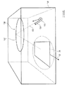
上述した特許文献1で提示される別の人工照明装置が図30に示される。光学コリメーション素子として、レンズ980が、光源からの一定の距離に位置し、光源は例示的にはレーザダイオード982及び(リモート)蛍光体984から構成される。ナノ拡散体をも含むレンズ980は、反射防止被膜されており、それによって、装置の効率性を低下させる反射を防ぐ、放射線の「温」成分、及びこの成分の外部領域への直接部分(ビームの直接部分)の透過を最適化し、コントラストを低下させる。さらに、図30の装置は、ナノ拡散体粒子により後方散乱された、後方に伝わる「冷」拡散光成分を取り出すための反射体986(例えば、蛍光体源984を収容し、且つレンズ980が位置する開口部を有する反射房又は反射箱)を備え、それによって、後方散乱拡散光を外側にリダイレクトする。よって、図30の照明装置は、要求されるCCTを有する直接光成分及び拡散光成分を提供する。   FIG. 30 shows another artificial lighting device presented in Patent Document 1 described above. As an optical collimation element, a lens 980 is located at a certain distance from the light source, and the light source is illustratively composed of a laser diode 982 and a (remote) phosphor 984. The lens 980, which also includes a nano-diffuser, is anti-reflective coated, thereby preventing reflection that reduces the efficiency of the device, and a direct portion (beam) of this component to the external region that prevents reflection. Optimize the transmission of the direct part) and reduce the contrast. In addition, the apparatus of FIG. 30 contains a reflector 986 (eg, a phosphor source 984 and a lens 980 is located) to extract back-transmitted “cold” diffuse light components backscattered by the nanodiffuser particles. A reflection chamber or a reflection box with an opening to thereby redirect the backscattered diffused light outward. Thus, the lighting device of FIG. 30 provides a direct light component and a diffuse light component having the required CCT.

しかしながら、図30に示されたそのような照明装置は、観察者によって知覚される少なくとも2つの異なる面の間での内部矛盾を有している、これらの面は、レンズ980の実像及び蛍光体源984の虚像の面であり、虚像面は、図29における装置のケースに関して、無限の距離でさえ知覚されない。加えて、図28のケースと同様に、図30の装置は、有限の距離で単一の光源を使用した照明から生じる典型的な放射状に対称的な外側に向かう挙動によって特徴付けられる影を落とす。   However, such an illuminating device shown in FIG. 30 has an internal discrepancy between at least two different surfaces perceived by the observer, these surfaces being the real image of the lens 980 and the phosphor. The virtual image plane of source 984, which is not perceived even at an infinite distance for the case of the device in FIG. In addition, similar to the case of FIG. 28, the apparatus of FIG. 30 casts a shadow characterized by typical radially symmetric outward behavior resulting from illumination using a single light source at a finite distance. .

上述した特許文献1で提示された更なる人工照明装置が図31に示される。ここで、光源990及び有色拡散体992は、全体的に分離しており、且つハウジング996の壁994の窓を形成する有色拡散体と相互に間隔を介している。しかしながら、選択された配置に因って、図31の装置により落とされる影は、有限の距離で単一の光源を使用した照明から生じる典型的な放射状に対称的な外側に向かう挙動を示している。最後に、光源990から生じるものではないが、周囲光から、すなわち、ハウジングの外部の環境から生じる、有色拡散体から観察者の目に入る周囲光は、観察者の空/太陽の印象を損ねる。   FIG. 31 shows a further artificial lighting device presented in Patent Document 1 described above. Here, the light source 990 and the colored diffuser 992 are entirely separated and are spaced from each other by the colored diffuser forming the window of the wall 994 of the housing 996. However, due to the chosen arrangement, the shadow cast by the apparatus of FIG. 31 shows a typical radially symmetric outward behavior resulting from illumination using a single light source at a finite distance. Yes. Finally, ambient light entering the viewer's eyes from a colored diffuser that does not originate from the light source 990, but from ambient light, ie from the environment outside the housing, detracts from the viewer's sky / sun impression. .

国際公開第2009/156347号International Publication No. 2009/156347

したがって、本発明の目的は、特に、平行し、鮮明、且つ照射された光景の残りよりも青みがかった影を形成することによって、実際の空及び太陽が行うような、周囲を照射し、且つ観察者が人工照明装置を直接見るときに、視覚キューの間の相互的矛盾及び内的矛盾がなく、空及び太陽の像の無限遠の視覚的な奥行き感を経験させるための自然光を合成する人工照明装置を提供することにある。   Therefore, the object of the present invention is to illuminate and observe the surroundings, especially as the real sky and the sun do, by creating a shadow that is parallel, sharp and bluer than the rest of the illuminated scene. Synthesizing natural light to allow viewers to experience the infinite visual depth of the sky and the sun image without mutual and internal contradictions between visual cues when looking directly at the artificial lighting device The object is to provide a lighting device.

この目的は、独立請求項の主題によって達成される。
有利な実装形態は、非独立請求項の主題である。
特に、本発明の好ましい実施形態が、図面に関して以下で説明される。
This object is achieved by the subject matter of the independent claims.
Advantageous implementations are the subject matter of the independent claims.
In particular, preferred embodiments of the invention are described below with reference to the drawings.

直接光源の例として、観察者の目が人工照明装置を見ているものとして示され、且つ得られる、拡散光発生器と組み合わされた第1の光放射デバイス及びコリメートレンズの対の配列を概略的に示す図である。As an example of a direct light source, an array of a first light emitting device and collimating lens pair in combination with a diffuse light generator is shown and obtained as the observer's eye is looking at an artificial illuminator. FIG. 直接光の輝度プロファイルを追加で概略的に示している、実施形態に従った人工照明装置を概略的に示す図である。FIG. 6 schematically illustrates an artificial lighting device according to an embodiment, additionally schematically illustrating a direct light luminance profile; 直接光の輝度プロファイルを追加で概略的に示している、実施形態に従った人工照明装置を概略的に示す図である。FIG. 6 schematically illustrates an artificial lighting device according to an embodiment, additionally schematically illustrating a direct light luminance profile; (A)は、図2A及び図2Bそれぞれの実施形態に従った直接光源及び拡散光発生器の配置の3次元概略図である。(B)は、図2A及び図2Bそれぞれの実施形態に従った直接光源及び拡散光発生器の配置の3次元概略図である。(A) is a three-dimensional schematic diagram of an arrangement of direct light sources and diffused light generators according to the respective embodiments of FIGS. 2A and 2B. FIG. 2B is a three-dimensional schematic diagram of an arrangement of direct light sources and diffused light generators according to the respective embodiments of FIGS. 2A and 2B. 直接光源の放射面を見ている観察者、及び観察者が放射面を見ているときの観察者に見える輝点を概略的に示す図である。It is a figure which shows roughly the bright spot seen by the observer who is looking at the radiation surface of a direct light source, and an observer when the observer is looking at the radiation surface. 実施形態に従った、適切な直接光源を提供するように適切に構成されたLEDの配列の断面図である。FIG. 3 is a cross-sectional view of an array of LEDs suitably configured to provide a suitable direct light source, according to an embodiment. 図5の配列の上面図である。FIG. 6 is a top view of the arrangement of FIG. 実施形態に従った、第1の光放射デバイス及びコリメートレンズの対を備える直接光源の部分透視図である。FIG. 4 is a partial perspective view of a direct light source comprising a first light emitting device and collimating lens pair, according to an embodiment. 更なる実施形態に従った、直接光源を提供するように図7に係る対の配列を3次元で示す図である。FIG. 8 shows in three dimensions an array of pairs according to FIG. 7 to provide a direct light source according to a further embodiment. 実施形態に従った端部照射型導光放射パネルを概略的に示す図である。It is a figure which shows schematically the edge part irradiation type light guide radiation panel according to embodiment. 端部照射型導光放射パネルの代替的な実施形態を示す図である。It is a figure which shows alternative embodiment of an edge part irradiation type | formula light guide radiation panel. 光学ミラー系、放射面の非透過背面照明、及び暗箱を使用した直接光源の実施形態の3次元概略図である。FIG. 3 is a three-dimensional schematic diagram of an embodiment of a direct light source using an optical mirror system, a non-transparent backlight of the radiation surface, and a dark box. 放射面に沿った側面方向の輝度変動を不明確にする格天井構造の3次元図である。It is a three-dimensional view of the case ceiling structure that makes the luminance variation in the side direction along the radiation surface unclear. 格天井構造が観察者によって見られ、且つ不明確さを生じさせる方法を概略的に示す図である。It is a figure which shows roughly the method by which a case ceiling structure is seen by an observer, and produces ambiguity. 均一な照明を達成するための自由形状レンズを含む、図7の直接光源を概略的に示す図である。FIG. 8 schematically shows the direct light source of FIG. 7 including a free-form lens for achieving uniform illumination. 均一な照明を達成するための集光器を含む、図7の直接光源を概略的に示す図である。FIG. 8 schematically illustrates the direct light source of FIG. 7 including a concentrator for achieving uniform illumination. 左側は元の分布曲線を示し、右側は放射面に沿った横次元での均一な照明を達成するための目標分布曲線を示す、図14A及び図14Bの自由形状レンズ及び集光器の、第1の光放射デバイスの光度分布曲線への目標となる影響を概略的に示す図である。The left side shows the original distribution curve and the right side shows the target distribution curve to achieve uniform illumination in the horizontal dimension along the emission surface, the first of the freeform lens and concentrator of FIGS. 14A and 14B. It is a figure which shows roughly the influence used as the target to the luminous intensity distribution curve of 1 light emitting device. 微小光学ビームホモジナイザ層を含む直接光源12を有する人工照明装置を概略的に示す図である。It is a figure which shows schematically the artificial illuminating device which has the direct light source 12 containing a micro optical beam homogenizer layer. 1つのレンズ配列及び1つのピンホール配列を備える、第1の実施形態に従った微小光学ビームホモジナイザ層の断面を概略的に示す図である。FIG. 2 schematically shows a cross section of a micro-optical beam homogenizer layer according to the first embodiment, comprising one lens arrangement and one pinhole arrangement. 図17Aのビームホモジナイザ層の上流面を示す図である。It is a figure which shows the upstream surface of the beam homogenizer layer of FIG. 17A. 図17Aのビームホモジナイザ層の下流面を示す図である。It is a figure which shows the downstream surface of the beam homogenizer layer of FIG. 17A. 1つのレンズ配列及び1つの管配列を備える、更なる実施形態に従った微小光学ビームホモジナイザ層の断面を概略的に示す図である。FIG. 6 schematically shows a cross section of a micro-optical beam homogenizer layer according to a further embodiment comprising one lens arrangement and one tube arrangement. 2つのレンズ配列及び1つのピンホール配列又は管配列を備える、微小光学ビームホモジナイザ層の更なる実施形態の断面を概略的に示す図である。FIG. 6 schematically shows a cross section of a further embodiment of a micro-optic beam homogenizer layer comprising two lens arrays and one pinhole array or tube array. 拡散光発生器の上流に位置する、低角度白色光拡散体を含む人工照明装置を概略的に示す図である。It is a figure which shows roughly the artificial lighting apparatus containing the low angle white light diffuser located upstream of a diffused light generator. 拡散光発生器の下流に位置する、低角度白色光拡散体を含む人工照明装置の更なる実施形態を概略的に示す図である。FIG. 6 schematically illustrates a further embodiment of an artificial lighting device including a low angle white light diffuser located downstream of a diffuse light generator. 直接光、透過光、及び拡散光の間のCCTオフセットを追加的に示す直接光源と拡散光発生器との組合せを含む人工照明装置を概略的に示す図である。FIG. 2 schematically illustrates an artificial lighting device including a combination of a direct light source and a diffuse light generator that additionally shows a CCT offset between direct light, transmitted light, and diffuse light. 直接光、透過光、及び拡散光の間でのCCTオフセットを追加的に示す直接光源と拡散光発生器との組合せを含む人工照明装置を概略的に示す図である。FIG. 2 schematically illustrates an artificial lighting device including a combination of a direct light source and a diffuse light generator that additionally shows a CCT offset between direct light, transmitted light and diffuse light. 直接光、透過光、及び拡散光の間でのCCTオフセットを追加的に示す直接光源と拡散光発生器との組合せを含む人工照明装置を概略的に示す図である。FIG. 2 schematically illustrates an artificial lighting device including a combination of a direct light source and a diffuse light generator that additionally shows a CCT offset between direct light, transmitted light and diffuse light. 拡散光発生器を実装する拡散体パネルを概略的に示す図である。It is a figure which shows roughly the diffuser panel which mounts a diffused light generator. (A)は、拡散光発生器を実装する拡散体パネルと拡散光源との組合せを概略的に示す図である。(B)は、拡散光発生器を実装する拡散体パネルと拡散光源との組合せを概略的に示す図である。(A) is a figure which shows roughly the combination of the diffuser panel and diffusion light source which mount a diffused light generator. (B) is a figure which shows roughly the combination of the diffuser panel and diffused light source which mount a diffused light generator. 拡散光発生器を実装する拡散光源を概略的に示す図である。It is a figure which shows roughly the diffused light source which mounts a diffused light generator. 実施形態に従った拡散光源の側面を概略的に示す図である。It is a figure which shows schematically the side surface of the diffused light source according to embodiment. 直接光と拡散光との間の関係、及びそれらの外側放射面における外側光への寄与に焦点をおいた一般的な用語での、異なる実施形態に従った人工照明装置及びそれの直接光源を概略的に示す図である。An artificial lighting device and its direct light source according to different embodiments in general terms focused on the relationship between direct light and diffused light and their contribution to outer light at the outer emission surface It is a figure shown roughly. 直接光と拡散光との間の関係、及びそれらの外側放射面における外側光への寄与に焦点をおいた一般的な用語での、異なる実施形態に従った人工照明装置及びそれの直接光源を概略的に示す図である。An artificial lighting device and its direct light source according to different embodiments in general terms focused on the relationship between direct light and diffused light and their contribution to outer light at the outer emission surface It is a figure shown roughly. 直接光と拡散光との間の関係、及びそれらの外側放射面における外側光への寄与に焦点をおいた一般的な用語での、異なる実施形態に従った人工照明装置及びそれの直接光源を概略的に示す図である。An artificial lighting device and its direct light source according to different embodiments in general terms focused on the relationship between direct light and diffused light and their contribution to outer light at the outer emission surface It is a figure shown roughly. 直接光と拡散光との間の関係、及びそれらの外側放射面における外側光への寄与に焦点をおいた一般的な用語での、異なる実施形態に従った人工照明装置及びそれの直接光源を概略的に示す図である。An artificial lighting device and its direct light source according to different embodiments in general terms focused on the relationship between direct light and diffused light and their contribution to outer light at the outer emission surface It is a figure shown roughly. 直接光と拡散光との間の関係、及びそれらの外側放射面における外側光への寄与に焦点をおいた一般的な用語での、異なる実施形態に従った人工照明装置及びそれの直接光源を概略的に示す図である。An artificial lighting device and its direct light source according to different embodiments in general terms focused on the relationship between direct light and diffused light and their contribution to outer light at the outer emission surface It is a figure shown roughly. 直接光と拡散光との間の関係、及びそれらの外側放射面における外側光への寄与に焦点をおいた一般的な用語での、異なる実施形態に従った人工照明装置及びそれの直接光源を概略的に示す図である。An artificial lighting device and its direct light source according to different embodiments in general terms focused on the relationship between direct light and diffused light and their contribution to outer light at the outer emission surface It is a figure shown roughly. 従来技術の人工照明装置の断面を概略的に示す図である。It is a figure which shows schematically the cross section of the artificial lighting apparatus of a prior art. 従来技術に従った更なる人工照明装置を概略的に示す図である。FIG. 2 schematically shows a further artificial lighting device according to the prior art. 従来技術に従った更なる人工照明装置を概略的に示す図である。FIG. 2 schematically shows a further artificial lighting device according to the prior art. 従来技術に従った更なる人工照明装置を概略的に示す図である。FIG. 2 schematically shows a further artificial lighting device according to the prior art.

既に紹介したように、空及び太陽からの自然照射の知覚は、照明装置により放射される光の一側面に依存し、それは、太陽からの光を再現する、低CCTで多大にコリメートされる直接光成分と、空の照明効果を再現する、高CCT拡散光成分とを特徴付けるはずであり、それによって、直接光成分が、照明装置により照射される対象物の鮮明且つ平行な影を落とすことが可能となり、且つ拡散光成分が、そのような影に青みがかった色の影を与える。一方、空及び太陽からの自然照射の知覚は、照明装置自体を直接見るときの空及び太陽像の無限の深さの知覚に依存する。   As already introduced, the perception of natural illumination from the sky and the sun depends on one aspect of the light emitted by the illuminator, which directly reproduces the light from the sun and is highly collimated at low CCT. It should characterize the light component and the high CCT diffuse light component that reproduces the sky lighting effect, so that the direct light component can cast a clear and parallel shadow of the object illuminated by the illuminator. A possible and diffuse light component gives such a shadow a bluish color. On the other hand, the perception of natural illumination from the sky and the sun depends on the perception of the infinite depth of the sky and the sun image when looking directly at the lighting device itself.

対象物の距離、よって3次元の光景を構成する見え方の深さを評価する観察者の能力は、集束、両眼視差及び輻輳、運動視差、輝度、大きさ、コントラスト、空気遠近法などに結び付けられる多数の生理学的及び心理学的なメカニズムに基づいている。いくつかのメカニズムは、観察条件(例えば、観察者が移動又は静止しているか、片眼又は両眼で見ているか、など)、及び光景の特性の両方に従って、他と比較して重要となることがあり、後者(光景の特性)は、例えば、既知の大きさ、距離、又は輝度を有する対象物が存在するかに依存し、光景の観察される要素がどの程度離れているかを評価する基準として機能する。特に、これらのメカニズムは、実像及び虚像の両方のケースに適用される。さらに具体的には、単一の視覚キュー、又は2以上の矛盾する異なる高レベルの視覚キューを理由に、観察者によって異なる深さで同時に知覚される2以上の異なる像の面の間に矛盾が存在するときに、視覚的不快感又は目の負担が生じることがある。
言い換えると、発明者は、深さの視覚が一連の視覚キューによって判定されると実際に気付いており、例えば、
(a)調節、すなわち、光景に焦点を合わせるための接眼レンズを適合させる毛様筋の動き、調節は数メートルの距離では最も効果的である。
(b)両眼輻輳、すなわち、観察者の2つの眼球の軸が同一の対象物上で収束する、すなわち、対象物が位置している面上で収束するという事実。
(c)運動視差、すなわち、移動している観察者によって見られる背景に対する対象物の明確な相対的な動き、運動視差から深さへの強いキューをごくわずかな身体のゆれのみからでさえ取得することができる。
(d)空気遠近法、すなわち、遠く離れた対象物が、大気によって散乱される光に因る低輝度コントラスト及び彩度を有するという事実。さらに、離れた対象物の色は、スペクトルの最後の青に向かってシフトされる。
(e)両眼視差、すなわち、観察者のそれぞれの目は、同一の光景のその自身の像を記憶する、わずかに異なる角度から見られるそのような2つの異なる像を使用することによって、観察者は、高度な精度で対象物への距離を三角測量することが可能になる。オートステレオグラム、3D映画、及び立体写真は、この視覚キューを使用して、2次元光景の奥行き感を得る。
(f)動きからの深さ、すなわち、対象物の大きさの動的な変化
(g)遠近法、すなわち、無限に集束する平行線の特性
(h)既知の対象物間の相対的大きさ
(i)他による対象物の遮断
The observer's ability to evaluate the distance of an object, and thus the depth of view that makes up a three-dimensional scene, includes focusing, binocular parallax and convergence, motion parallax, brightness, size, contrast, air perspective Based on numerous physiological and psychological mechanisms that are linked. Some mechanisms are important compared to others, both according to viewing conditions (eg, whether the viewer is moving or stationary, looking with one or both eyes, etc.) and the characteristics of the scene The latter (scene characteristics), for example, evaluates how far the observed elements of the scene are, depending on the presence of objects of known size, distance, or brightness. Serves as a reference. In particular, these mechanisms apply to both real and virtual image cases. More specifically, because of a single visual cue, or two or more contradicting different high-level visual cues, a discrepancy between two or more different image planes perceived simultaneously at different depths by an observer When present, visual discomfort or eye strain may occur.
In other words, the inventor has actually realized that depth vision is determined by a series of visual cues, for example,
(A) Adjustment, i.e. movement of the ciliary muscle to adjust the eyepiece to focus on the scene, adjustment is most effective at distances of several meters.
(B) Binocular convergence, i.e. the fact that the axes of the two eyes of the observer converge on the same object, i.e. on the plane where the object is located.
(C) Acquire motion parallax, ie a clear relative movement of the object relative to the background seen by a moving observer, a strong cue from motion parallax to depth, even from very little bodily shaking can do.
(D) Air perspective, that is, the fact that an object that is far away has low brightness contrast and saturation due to light scattered by the atmosphere. Furthermore, the color of the distant object is shifted towards the last blue of the spectrum.
(E) binocular parallax, ie, each eye of the observer observes by using two such different images viewed from slightly different angles, storing their own image of the same scene The person can triangulate the distance to the object with high accuracy. Autostereograms, 3D movies, and stereoscopic photographs use this visual cue to get a sense of depth in a two-dimensional scene.
(F) Dynamic change in depth from motion, i.e. object size (g) Perspective, i.e. properties of infinitely focused parallel lines (h) Relative size between known objects (I) Blocking objects by others

実際の空及び太陽が本来行っているように見える照明装置の要件の1つを表す、空及び太陽の無限の奥行き感が、特に、両眼輻輳、運動視差、及び調節視覚的奥行き感キューなどの相乗効果によって一貫してサポートされるとき、すなわち、上述したそれらの視覚キューの間に矛盾が存在しないときに、実現される。空気遠近法は、空及び太陽の像の無限の深さの知覚にもさらに寄与する。
発明者はまた、視覚の矛盾が以下の2つの主要な理由によって生じることを気付いた。
(a)内的矛盾と称される、単一の視覚キューに応じた2以上の異なる深さ面の間の不明瞭さ
(b)相互的矛盾と称される、異なる視覚キューから派生する情報の間の矛盾
The infinite depth of the sky and the sun, which represents one of the requirements of the luminaire that the natural sky and the sun seem to do, especially binocular vergence, motion parallax, and adjusted visual depth cues This is achieved when it is consistently supported by the synergistic effects of the above, i.e. when there is no conflict between those visual cues mentioned above. The air perspective further contributes to the perception of infinite depth of sky and sun images.
The inventor has also noticed that the visual contradiction arises for two main reasons:
(A) ambiguity between two or more different depth planes depending on a single visual cue, referred to as an internal discrepancy (b) information derived from different visual cues, referred to as a mutual discrepancy Contradiction between

視覚的奥行き感のキューの間の内的矛盾及び相互的矛盾がないことは、太陽及び空の両方の無限の深さの自然な知覚をもたらすために必須である。さらに、キューの間での一致の欠如を避けることによって、目の負担及び不快感を回避することができるとともに、見ることの快感を高める。   The absence of internal and mutual contradictions between visual depth cues is essential to provide a natural perception of infinite depth in both the sun and the sky. Furthermore, avoiding the lack of coincidence between cues can avoid eye strain and discomfort and increase the pleasure of viewing.

例えば、図29で示した上述した人工照明装置を既に参照した。特に、光源902を直接見るとき、2つの矛盾する像が観察者によって同時に知覚される。レイリーパネルの固有の透過性に起因する第1の像は、LEDの配列、調節及びLEDの配列面上の両眼輻輳によって特にサポートされる有限の距離、並びに運動視差の実像である。第2の像は、無限に知覚される、青みがかった背景によって囲まれる輝点の虚像である。この第2の像は、各LED910がすべての他のLEDのそれらと同一の分岐及び配光を有する円形対称光円錐を光らせる限り、それぞれの目によって見られるLED910のグループが、観察者の目の網膜において円形スポットを形成するという事実によって与えられる。言い換えると、LED910は、図29のケースではパネル906に垂直なLEDの配列方向によって与えられる固定した方向、及びLEDの分岐の円錐角と一致する固定した開口角を有する円錐の下で見られる。特に、観察者の目の各々は、所与の方向及び円錐角の下に、照射されたLED910のその自身のグループを見る。これらの輝点は、無限の距離で両眼輻輳によって知覚され、これは、通常の視覚が要求するように、網膜上でそのような円形スポットの同一の中心像を作り出す状況である。この輝点の大きさは、各々の単一のLED素子910によって放射される光の角分岐に依存する。   For example, the above-described artificial lighting device shown in FIG. 29 has already been referred to. In particular, when viewing the light source 902 directly, two contradictory images are perceived simultaneously by the viewer. The first image due to the inherent transparency of the Rayleigh panel is a real image of the LED array, the finite distance specifically supported by the accommodation and binocular convergence on the LED array plane, and the motion parallax. The second image is a virtual image of a bright spot surrounded by a bluish background that is perceived indefinitely. This second image shows that as long as each LED 910 shines a circular symmetric light cone with the same branching and light distribution as those of all other LEDs, the group of LEDs 910 seen by each eye Given by the fact that it forms a circular spot in the retina. In other words, the LED 910 is seen under a cone having a fixed direction given by the LED alignment direction perpendicular to the panel 906 in the case of FIG. 29 and a fixed opening angle that matches the cone angle of the LED branch. In particular, each of the observer's eyes sees its own group of illuminated LEDs 910 under a given direction and cone angle. These bright spots are perceived by binocular convergence at infinite distances, a situation that creates the same central image of such a circular spot on the retina as required by normal vision. The size of this bright spot depends on the angular branching of light emitted by each single LED element 910.

光源902は、第1の像面、すなわち、LED910の配列の実像の面が、光源902を直接見る観察者によって見られることを妨げるいかなるメカニズムをも含まないので、異なる面において知覚された2つの上述した像の間で、視覚矛盾が生じる。よって、例えば、両眼輻輳によって判定される内的矛盾として説明することができるこの矛盾は、観察者が自然の空及び太陽の見え方を知覚することを妨げる。特に、そのような知覚矛盾によって、図29における装置は、本発明の根底にある技術的課題を解決するのに不適格である。言い換えると、観察者が円形輝点からの温光成分、直接光成分のみでなく、LED配列全体からの温光成分、直接光成分をも見ているので、矛盾が生じる。実際には、LEDからの光のほとんどが、分岐円錐の内部で光っている場合でさえ、無視できない部分は未だに、それの外側で光っており(例えば、ドーム状LED装置910の内部で発散が発生していることを理由に、及びドーム状レンズが撮像光学部品では全くないという事実を理由に)、そのことによって、観察の任意のほとんどの角度からの照射対象物として、照射されたLEDが明確に可視的なものとなる。   The light source 902 does not include any mechanism that prevents the first image plane, i.e., the real image plane of the array of LEDs 910, from being viewed by an observer looking directly at the light source 902, so that two perceived in different planes. A visual contradiction occurs between the above-mentioned images. Thus, for example, this contradiction, which can be described as an internal contradiction determined by binocular congestion, prevents the observer from perceiving the natural sky and the sun's appearance. In particular, due to such perceptual contradiction, the apparatus in FIG. 29 is ineligible for solving the technical problem underlying the present invention. In other words, the observer sees not only the warm light component and direct light component from the circular luminescent spot, but also the warm light component and direct light component from the entire LED array, so a contradiction arises. In practice, even if most of the light from the LED is shining inside the branch cone, a non-negligible part is still shining outside of it (eg, divergence inside the dome-shaped LED device 910). (Because it occurs, and because of the fact that the dome-shaped lens is not an imaging optic), this allows the illuminated LED to be illuminated as an object to be illuminated from almost any angle of observation. It will be clearly visible.

大角度での、すなわち、LEDの分岐円錐の外部での、LEDによって生成される背景光は、全く均一でなく、且つLEDのピッチ周期に従う。そのような均一の不存在は、大角度でのLEDに因る平均輝度が輝点に対して非常に低い場合でさえ、且つそれが拡散光発生器の均一な輝度に対しても弱い場合でさえ、有限の距離でのLED配列の第1の像を、無限の距離での輝点の第2の像上に広がらせる主要な理由として、発明者によって理解される。実際には、人類の目は、輝度の空間的勾配に対して、特に輝度の空間的周期変調に対して非常に敏感である。   The background light generated by the LED at a large angle, i.e. outside the LED branch cone, is not uniform at all and follows the pitch period of the LED. Such non-uniformity exists even when the average brightness due to the LED at a large angle is very low relative to the bright spot and when it is weak to the uniform brightness of the diffuse light generator. Even, it is understood by the inventor as the main reason for spreading the first image of the LED array at a finite distance over the second image of the bright spot at an infinite distance. In practice, the human eye is very sensitive to the spatial gradient of luminance, in particular to the spatial periodic modulation of luminance.

さらに、大角度でのLEDによって生成される背景光は、例えば、図28で説明された実施形態のケースに対して、結果として生じる色が、澄んだ空からの光の色と相当に異なるという意味で、拡散光の色品質を多大に損なう。   Furthermore, the background light produced by the LED at a large angle is, for example, that the resulting color is considerably different from the color of the light from the clear sky, for the case of the embodiment described in FIG. In a sense, the color quality of diffused light is greatly impaired.

パネルを超えてLED配列全体を観察者が明確に見ているという事実は、LED光源からの背景への寄与が、レイリーパネル自体からのそれを克服することから、背景の均一性及び色の両方を損なう。結果として、自然の空及び太陽の光景の色及び実質的に無限の奥行き感のいずれもが、図29の装置によって再生されない。   The fact that the observer clearly sees the entire LED array beyond the panel is that both the background uniformity and color, since the contribution from the LED light source to the background overcomes that from the Rayleigh panel itself. Damage. As a result, neither the color of the natural sky and the sun scene nor the virtually infinite depth of sensation is reproduced by the device of FIG.

さらに、商業的な、ドーム状の装備されたLEDによって達成可能な最小の分岐は概して、数10度の階数、すなわち、実際の太陽ビームの分岐を特徴付ける0.5度の値よりもはるかに大きい数字の分岐である。この制限によって、光源902に対し自然の一つよりもはるかに大きい半影の角度が生じる。結果として、対象物の影であるが莫大な大きさを有するそれらが全く生成されず、その大きな対象物の影の鮮明さは、とにかく非常に弱い。LED光ビームの分岐は、より大きなコリメータ、例えば、商業的に利用可能なTIR(全反射)レンズ、又はCPC(複合放物集光器)反射体を使用することによって、例えば、6度から7度程度の低い値に低減される。しかしながら、この選択は、無限の深さの知覚をサポートすることを補助することにならず、これらの大きなコリメータは、標準的なLEDドームよりも、目によってさらに容易にスポットされる非常に粗い画素化に通じる。   Furthermore, the minimum branching achievable with commercial, domed-equipped LEDs is generally much higher than the tens of degrees, ie, the 0.5 degree value that characterizes the actual solar beam branching. It is a branch of numbers. This limitation results in a penumbra angle for the light source 902 that is much greater than one of nature. As a result, no shadows of the object but those of enormous size are generated at all, and the sharpness of the shadow of the large object is very weak anyway. The branching of the LED light beam can be achieved, for example, from 6 degrees to 7 by using a larger collimator, such as a commercially available TIR (total reflection) lens, or CPC (compound parabolic concentrator) reflector. It is reduced to a low value. However, this choice does not help support infinite depth perception, and these large collimators are very coarse pixels that are spotted more easily by the eye than a standard LED dome. Leads to

実際に、自然の空及び太陽の視覚的な見え方において不利な、図29に示された光源902の更なる問題は、輝点、すなわち、そのような輝点が観察される角度上の知覚可能な画素化である。実際には、多大にコリメートされたLEDは、標準的なドームよりも通常ははるかに大きい、すなわち、約1cm以上のレンズ(よってピッチ)の大きさにつながり、非常に少ない画素、すなわち、LED/レンズの対によって形成されることになる輝点を生じさせ、スポットが観察されるより低い円錐角を理由に、及びレンズの大きさの増加を理由に、LED分岐の減少とともに数が減少する。この状況で、無限の深さの面に対応する虚像は、2つの非常に異なる画素化された像に分離し、それらの像によって、LEDの配列面の知覚が無限の深さ像上で広がる。よって、そのような状況によって、観察者が無意識に太陽の像に対する無限の深さを知覚することが妨げられる。   Indeed, a further problem with the light source 902 shown in FIG. 29, which is detrimental to the visual appearance of the natural sky and the sun, is the bright spot, ie the perception on the angle at which such a bright spot is observed. Possible pixelization. In practice, highly collimated LEDs are usually much larger than standard dome, i.e., lead to lens size (and hence pitch) of about 1 cm or more, and very few pixels, i.e. LED / The number decreases with decreasing LED branching, due to the lower cone angle at which the spot is observed, and because of the increased lens size, resulting in bright spots that will be formed by the lens pair. In this situation, the virtual image corresponding to the infinite depth plane separates into two very different pixelated images, which spread the perception of the LED array plane over the infinite depth image. . Thus, such a situation prevents the viewer from unknowingly perceiving infinite depth relative to the sun image.

さらに、周囲光の効果、すなわち、照明装置又はいくつかの他の光源によって照らされる周囲から来る光、及びレイリー散乱パネル906を上流/逆方向に交差させる、LED910の配列を再度照らす光の効果とともに、レイリーパネル906によってLED配列に向かって反射又は拡散される光の効果が考慮されるべきである。概してすべての方向から来る、すなわち、拡散されたこの光は、LED配列の可視性をさらに高める、好ましくない寄与をもたらす。言い換えると、図29の装置は、周囲からの光フィードバックが役割を果たさないときに発生するように、オフに切り替わったときでさえ黒くない。   In addition, with the effect of ambient light, ie light coming from the surroundings illuminated by the lighting device or some other light source, and the effect of light illuminating the array of LEDs 910 crossing the Rayleigh scattering panel 906 upstream / reversely The effect of light reflected or diffused towards the LED array by the Rayleigh panel 906 should be considered. This light, which generally comes from all directions, ie diffused, provides an undesirable contribution that further increases the visibility of the LED array. In other words, the device of FIG. 29 is not black even when switched off, as occurs when optical feedback from the surroundings does not play a role.

要約すると、図29の装置は本発明の根底にある技術的課題を解決することができない。何故ならば、観察者が直接装置自身を見ているとき、同時に発生する視覚面の間での視覚キューの矛盾を引き起こし、それらの面は例えば、LED910の配列の実像、及び太陽に対応する輝点の虚像であるので、実際の空及び太陽としての視覚的な見え方の要件を満たさないからである。さらに、輝点が知覚される大きな円錐角、及びそのような虚像の明確に知覚可能な画素化に因って、太陽に対応する像を的確に表すことができない。   In summary, the device of FIG. 29 cannot solve the technical problem underlying the present invention. This is because when the observer is looking directly at the device itself, it causes visual cue discrepancies between the simultaneous visual planes, such as the real image of the array of LEDs 910 and the brightness corresponding to the sun. This is because it is a virtual image of a point and does not satisfy the requirement of visual appearance as the actual sky and the sun. Furthermore, due to the large cone angle at which bright spots are perceived and the clearly perceivable pixelation of such virtual images, images corresponding to the sun cannot be accurately represented.

装置が無限の深さの視覚的な経験を作り出すことを妨げる視覚キューの間での矛盾の発生の更なる例として、図30に示した既に述べた実施形態への参照がなされる。この点において、コリメーション及びレイリー散乱の両方を実行することに代わって、単一の光学素子の使用によって、直接光及び拡散光の両方を可能な限り前方方向に案内することによって、輝度効率を最大化するために、実施形態が最適化されることに触れる価値がある。処理能力を高めるために、逆散乱光を前方方向にリダイレクトする反射防止被膜及び反射房が提供される。特に、レンズ980からの焦点距離に位置する温光源984を必要とする、最小分岐を有する温(例えば、低CCT)直接光を生成するために、図30の装置では何ら努力がなされていない。一方で、図30から明らかなように、光源984はレンズのより近くに位置し、目的は、レンズによる集光量を最大化することであって、平行光線を生成することではない。   As a further example of the occurrence of discrepancies between visual cues that prevent the device from creating an infinite depth visual experience, reference is made to the previously described embodiment shown in FIG. In this regard, instead of performing both collimation and Rayleigh scattering, the use of a single optical element maximizes luminance efficiency by guiding both direct and diffused light as far forward as possible. It is worth mentioning that the embodiments are optimized to In order to increase throughput, anti-reflection coatings and tufts that redirect backscattered light in the forward direction are provided. In particular, no effort has been made in the apparatus of FIG. 30 to generate warm (eg, low CCT) direct light with minimal branching that requires a warm light source 984 located at the focal length from lens 980. On the other hand, as is clear from FIG. 30, the light source 984 is located closer to the lens, and the purpose is to maximize the amount of light collected by the lens, not to generate parallel rays.

レンズから光源984の短い距離に起因して、蛍光体からレンズへの光線経路がより長く、且つ傾斜角度がより大きい(照射への各光線の寄与は、入射角のコサイン倍の経路長の2乗の逆数に比例する)ことに因って、レンズの円周部に存在する温光は中心よりも弱い。実際には、レンズの外側部分上の60度の平均入射角を想定すると、差異が係数8としてのレンズにわたる温光輝度変動につながることがあり、それは、レイリー拡散体の輝度における強い空間変調をもたらす。ここで、照度(光源984からの)が小さくなる場合に拡散体の密度が下がるので、不均一さが更に増す。   Due to the short distance of the light source 984 from the lens, the ray path from the phosphor to the lens is longer and the tilt angle is larger (the contribution of each ray to illumination is 2 of the path length of cosine times the incident angle). Is proportional to the reciprocal of the power), the warm light present at the circumference of the lens is weaker than the center. In fact, assuming an average angle of incidence of 60 degrees on the outer part of the lens, the difference can lead to warm-intensity fluctuations across the lens as a factor of 8, which results in strong spatial modulation in the brightness of the Rayleigh diffuser. Bring. Here, when the illuminance (from the light source 984) decreases, the density of the diffuser decreases, further increasing the non-uniformity.

したがって、図30に示す装置は未だに、観察者が人工照明に関する自然な感覚を得ることを妨げる、視覚的キューの矛盾を含む(それに限定されない)、いくつかの問題を抱えている。実際に、温光源984とレンズとの間の短い距離によって、光の虚像が、太陽の自然な像に対して生じるものと異なって、無限の距離で現れることが生じる。さらに、(レンズ)レイリー拡散体の不均質な照明によって、不均質な空−輝度プロファイルが生じ、空輝度プロファイルによって、視覚キューが、実像面と虚像面との間のキュー矛盾を判定する、装置面における照射レンズの実像を形成する。加えて、光源とレンズとの間の同一の近距離は、図30の装置が、実際の太陽のケースと異なり、典型的な放射状に対称的な外側に向かう挙動によって特徴付けられる影を落とすことにつながる。最終的に、反射体箱986は、観察者に向かって、いくつかの照射寄与物を照らす、すなわち、照射寄与物は、光源984から直接来る光、2つのレンズ−空気境界面から反射される光、ナノ拡散体から逆散乱される光、並びにレンズ下流の照射された光景から来る光、及び上流方向にレンズを交差させる光、である。結果として、反射体箱によって更に、レンズの像面と光の像面との間の中間位置において、レイリー拡散体を超える、不均質且つ発光背景を作り出すことによって、いずれかの潜在的な大きな深さの視覚的経験が妨げられる。特に、レイリー散乱光の色とは異なる色を有する、光源984からの光と、周囲から反射された背景への光との寄与に因って、反射体箱986によって、拡散光の色が空の光の実際の色とは異なることが生じ、よって、空の自然な見え方を損ね、且つ知覚された深さを深める空気遠近法に関連する潜在的な好ましい効果を妨げる。要するに、図30の装置は、本発明の根底にある技術的課題を解決することができない。何故ならば、観察者が装置自体を直接見るときの実際の空及び太陽としての視覚的な見え方の要件と、空及び太陽によって行われるような周囲を照射する要件との両方を満たさないからである。   Thus, the apparatus shown in FIG. 30 still has several problems, including but not limited to visual cue conflicts that prevent the viewer from getting a natural sense of artificial lighting. In fact, the short distance between the warm light source 984 and the lens can cause the virtual image of light to appear at an infinite distance, unlike that produced for the natural image of the sun. In addition, the inhomogeneous illumination of the (lens) Rayleigh diffuser results in an inhomogeneous sky-luminance profile, whereby the visual cues determine the cue discrepancy between the real and virtual image planes. A real image of the illumination lens on the surface is formed. In addition, the same short distance between the light source and the lens causes the device of FIG. 30 to cast a shadow characterized by a typical radially symmetric outward behavior, unlike the actual sun case. Leads to. Eventually, the reflector box 986 illuminates several illumination contributions towards the viewer, i.e. the illumination contributions are reflected directly from the light source 984 and from the two lens-air interfaces. Light, backscattered from the nanodiffuse, light coming from the illuminated scene downstream of the lens, and light crossing the lens in the upstream direction. As a result, the reflector box further creates any potential large depth by creating an inhomogeneous and luminescent background that exceeds the Rayleigh diffuser at an intermediate position between the lens image plane and the light image plane. The visual experience is hindered. In particular, due to the contribution of light from the light source 984, which has a color different from the color of the Rayleigh scattered light, and the light reflected from the surroundings to the background, the reflector box 986 causes the diffuse light color to be emptied. Differ from the actual color of the light, thus compromising the natural appearance of the sky and hindering the potential positive effects associated with air perspective that increase the perceived depth. In short, the apparatus of FIG. 30 cannot solve the technical problem underlying the present invention. This is because the observer does not meet both the requirement of visual appearance as the actual sky and sun when looking directly at the device itself and the requirement of illuminating the surroundings as is done by the sky and sun. It is.

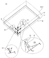
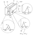
同一の光源の配列のケースで、輝点の虚像を無限の距離で形成することができるメカニズムをさらに明確にするために、本発明の発明者は図1に例示されるような図29に示された構造を概念化した。すなわち、拡散光発生器10が、第1の光放射デバイス14の2次元配列で構成された直接光源12に対して下流に位置し、各々の第1の光放射デバイス14は、それぞれの第1の光放射デバイス14によって出力される光をコリメートするように、それに関連付けられたコリメータ16を有する。拡散光発生器10は、レイリーライク拡散体であってもよく、又は以下でさらに詳細に述べられるような、代替的に若しくは追加的に、直接光源12によって生成されるコリメート光に対して少なくとも部分的に透過的な拡散光源を備えてもよい。図1はまた、全体的に、参照符号20で示される人工照明装置の方向を見ている観察者の目18及び18を示す。図1では、目18及び18は、両眼視力に因って、観察者は必然的にそれぞれの網膜22上の同一の位置で2つの太陽の像を有することを試みることから、本来的に無限遠に設定される。拡散光発生器10がコリメータ16の面の近くに配置されていることに因って、目18及び18は、青い空の環境での丸い太陽を見ることになる。特に、部屋の中で歩くことによって、目は、パネルを交差する視太陽を、それが実際に起こっているように見る。光源の角スペクトルがフラットトップでないが鐘形である場合、太陽の像は鮮明でなく青みがかることになる。図1が無限の距離での輝点の虚像の形成のみに関係していることが思い出される一方で、目の調節及びLED配列面への収束によって形成され、且つ図29で示された装置が、空及び太陽の自然の視覚的な見え方を保証することを妨げる、LED配列の実像を考慮していない。 In order to further clarify the mechanism by which virtual images of bright spots can be formed at infinite distances in the case of the same light source arrangement, the inventors of the present invention show in FIG. 29 as illustrated in FIG. Conceptualized the structure. That is, the diffuse light generator 10 is located downstream with respect to the direct light source 12 configured with a two-dimensional array of first light emitting devices 14, and each first light emitting device 14 has a respective first light emitting device 14. A collimator 16 associated therewith to collimate the light output by the light emitting device 14. The diffuse light generator 10 may be a Rayleigh-like diffuser, or alternatively or in addition, as described in more detail below, at least partially with respect to collimated light generated by the direct light source 12. A transparent diffusing light source may be provided. FIG. 1 also generally shows the viewer's eyes 18 L and 18 R looking at the direction of the artificial lighting device indicated by reference numeral 20. In FIG. 1, the eyes 18 L and 18 R are inherently due to the binocular vision, because the observer necessarily tries to have two images of the sun at the same location on each retina 22. Is set to infinity. Diffused light generator 10 is due to being positioned near the surface of the collimator 16, the eye 18 L and 18 R will see a round sun in blue sky environment. In particular, by walking in the room, the eye sees the sighting sun crossing the panels as if it were actually happening. If the angular spectrum of the light source is not flat-top but bell-shaped, the sun image will not be clear and bluish. While it is recalled that FIG. 1 relates only to the formation of bright spot virtual images at infinite distances, the apparatus shown in FIG. 29 formed by eye adjustment and convergence to the LED array plane is shown. It does not take into account the real image of the LED array, which precludes ensuring the natural visual appearance of the sky and the sun.

図2Aは、太陽及び空が窓を介して行うような周囲を照射することが可能であり、且つ空及び太陽が窓を介して観察されるときに本来行うのと同時に、実質的に無限の深さの経験を保証する照明装置の視覚的な見え方を保証する、本発明に従った実施形態を示している。   FIG. 2A shows that it is possible to illuminate the surroundings as the sun and sky do through the window, and at essentially the same time as it does when the sky and sun are observed through the window. Fig. 4 shows an embodiment according to the invention that guarantees the visual appearance of a lighting device that guarantees depth experience;

言い換えると、実施形態は、太陽及び空のように、すなわち、太陽及び空からの光と類似する輝度プロファイル及び見え方を有する、自然光を生成する人工照明装置20を示している。   In other words, the embodiment shows an artificial lighting device 20 that produces natural light, like the sun and sky, i.e. having a brightness profile and appearance similar to light from the sun and sky.

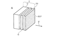
図2Aの人工照明装置は、直接光源を備えている。図2の理解を軽減する目的で、直接光源の第1の放射面28が単に示されている。しかしながら、図1から明確になり、且つ以下の図面からより明確になるように(図示しない)、直接光源は、主要光を放射するように構成され、且つ光放射面に対して上流に位置する第1の光放射デバイスを備えている。直接光源12は、主要光から直接光236を生成するように構成され、直接光236は、第1の放射面28にわたって均一な(例えば、空間依存性に関して)輝度プロファイルLdirect(x、y、θ、φ)を有する第1の放射面28を出射し、且つ直接光方向32に沿って狭いピーク30(すなわち、角度依存に関して)を有し、x及びyは、第1の放射面28に及ぶ軸x及びyに沿った横軸座標であり、θは、直接光方向32に対して測定される極角(polar angle)であり、φは、方位角(azimuthal angle)である。用語「狭い」は、以下で更に明確にされるが、概して、Ldirect(x、y、θ、φ)が2πsrよりも非常に小さく、例えば、0.4srよりも小さく、好ましくは0.3srよりも小さく、更に好ましくは0.2srよりも小さい、立体角によって定められるピークを有する、として理解されてもよい。さらに、図2Aの人工照明装置はまた、第1の放射面28の下流に位置するとしても例示されていない、拡散光発生器10を備えている。拡散光発生器10は、第2の放射面34及び第2の放射面と対向する入力面33を備え、且つ少なくとも部分的に、入力面33上に影響する光に対して透過的になるように構成されている。さらに、拡散光発生器10は、第2の放射面34から拡散光35を放射するように構成され、拡散光35は、実質的にすべての前方方向に散乱され、且つ空間座標x、yに応じて均一又は少なくとも弱い、第2の放射面34を出射する、外側光の成分である。例えば、拡散光発生器10は、狭いピーク30を定める立体角の少なくとも4倍大きく、好ましくは9倍大きく、より好ましくは16倍大きい立体角上で、拡散光を放射するように構成されている。 The artificial lighting device of FIG. 2A includes a direct light source. For the purpose of reducing the understanding of FIG. 2, the first light emitting surface 28 of the direct light source is merely shown. However, as will become clear from FIG. 1 and from the following figures (not shown), the direct light source is configured to emit the main light and is located upstream with respect to the light emitting surface. A first light emitting device is provided. The direct light source 12 is configured to generate direct light 236 from the primary light, which direct light 236 is uniform (eg, with respect to spatial dependence) the luminance profile L direct (x, y, exits the first radiation surface 28 with θ, φ) and has a narrow peak 30 (ie with respect to angular dependence) directly along the light direction 32, x and y are at the first radiation surface 28. The abscissa coordinates along the extending axes x and y, θ is the polar angle measured with respect to the direct light direction 32, and φ is the azimuthal angle. The term “narrow” will be further clarified below, but in general, L direct (x, y, θ, φ) is much less than 2πsr, eg, less than 0.4 sr, preferably 0.3 sr. May be understood as having a peak defined by a solid angle that is less than, more preferably less than 0.2 sr. In addition, the artificial lighting device of FIG. 2A also includes a diffused light generator 10, which is not illustrated if located downstream of the first radiation surface 28. The diffused light generator 10 includes a second radiation surface 34 and an input surface 33 that faces the second radiation surface, and is at least partially transparent to light that affects the input surface 33. It is configured. Furthermore, the diffused light generator 10 is configured to emit diffused light 35 from the second radiation surface 34, the diffused light 35 being scattered in substantially all forward directions and in spatial coordinates x, y. It is the component of the outside light that exits the second radiation surface 34, which is uniform or at least weak accordingly. For example, the diffuse light generator 10 is configured to emit diffuse light over a solid angle that is at least 4 times larger, preferably 9 times larger, more preferably 16 times larger than the solid angle defining the narrow peak 30. .

加えて、図2Aの装置は、直接光源12によって生成される直接光236が、拡散光35のCCTよりも低い(例えば、少なくとも1.2倍低い、好ましくは1.3倍低い、より好ましくは1.4低い)CCTを有するように構成されている。拡散光発生器10が少なくとも部分的に光透過であるという事実に因って、直接光236の少なくとも一部は、第2の放射面34の下流に伝播する。結果として、外側光は、狭いピーク30内に含まれる方向に沿って(例えば、狭いピーク30を定める方向の少なくとも90%に沿って、すなわち、狭いピークのHWHM極角よりも小さい極角θを有する方向の90%に沿って)伝播する第1の光成分と、狭いピーク30から間隔を介した方向、例えば、方向32及び狭いピークのHWHM極角よりも3倍大きい半開口部に沿って向けられた軸を有する円錐の外側の角領域の少なくとも30%、好ましくは50%、最も好ましくは90%に及ぶ方向、に沿って伝播する第2の光成分とを備えている。   In addition, the apparatus of FIG. 2A is such that the direct light 236 generated by the direct light source 12 is lower than the CCT of the diffused light 35 (eg, at least 1.2 times lower, preferably 1.3 times lower, more preferably 1.4 low) configured to have a CCT. Due to the fact that the diffuse light generator 10 is at least partially light transmissive, at least a portion of the direct light 236 propagates downstream of the second emitting surface 34. As a result, the outer light has a polar angle θ along the direction contained within the narrow peak 30 (eg, along at least 90% of the direction defining the narrow peak 30, ie, less than the HWHM polar angle of the narrow peak. A first light component that propagates (along 90% of the direction it has) and a direction spaced from the narrow peak 30, eg, along a half-opening that is three times larger than the HWHM polar angle of direction 32 and the narrow peak. A second light component propagating along a direction extending at least 30%, preferably 50%, most preferably 90% of the outer corner region of the cone having an oriented axis.

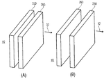
図2Bに示される更なる実施形態では、第1の放射面28及び第2の放射面34の相互位置は、図2Aのケースに対して逆になる。言い換えると、図2Aのケースでは、第2の放射面34が装置20の外側面37を形成し、図2Bのケースでは、第1の放射面28が装置20の外側面37を形成する。   In a further embodiment shown in FIG. 2B, the mutual position of the first radiating surface 28 and the second radiating surface 34 is reversed relative to the case of FIG. 2A. In other words, in the case of FIG. 2A, the second radiating surface 34 forms the outer surface 37 of the device 20, and in the case of FIG. 2B, the first radiating surface 28 forms the outer surface 37 of the device 20.

具体的には、図2Bの実施形態は、主要光(図示せず)を放射するように構成された第1の光放射デバイス14(図示せず)及び直接光源の下流に位置する第1の放射面28を備える直接光源(図示せず)を備える人工照明装置に言及し、直接光源12は、輝度プロファイルLdirect(x、y、θ、φ)を有する第1の放射面28を出射する直接光236を、主要光から生成するように構成されており、輝度プロファイルは、第1の放射面28にわたって均一であり(例えば、空間依存性に関して)、且つ直接光方向32に沿って狭いピーク30を有する(すなわち、角度依存性に関して)。さらに、図2Bにおける実施形態はまた、第1の光放射デバイスの下流に位置し、且つ第1の放射面28の上流に位置し(すなわち、直接光源12の内部に位置する)、且つ少なくとも部分的に主要光、すなわち、入力面33上に影響する光に対して透過的であり、第2の放射面34から拡散光35を放射するように構成された拡散光発生器10(図示せず)を備えており、拡散光35は、実質的にすべての前方方向に散乱され、且つ空間座標x、yに応じて均一又は少なくとも弱い、第2の放射面34を出射する光の成分である。したがって、図2Bにおける実施形態について、第1の放射面28は、第2の放射面34の下流に位置し、輝度プロファイルLdirect(x、y、θ、φ)は、第1の放射面28における輝度であり、拡散光発生器10は、系から物理的に除去される。図2Bの実施形態では、照明装置は、主要光14が、拡散光35のCCTよりも低いCCT(例えば、少なくとも1.2倍低く、好ましくは1.3倍低く、より好ましくは1.4倍低い)を有するように構成されている。拡散光発生器10が少なくとも部分的に光透過であるという事実に因って、第1の放射面28における外側光は、狭いピーク30内に含まれる方向に沿って伝播する第1の光成分と、狭いピーク30と間隔を介した方向に沿って伝播する第2の光成分とを備え、第1の光成分は、第2の光成分のCCTよりも低いCCTを有する。 Specifically, the embodiment of FIG. 2B includes a first light emitting device 14 (not shown) configured to emit primary light (not shown) and a first located directly downstream of the light source. Reference is made to an artificial lighting device comprising a direct light source (not shown) comprising a radiation surface 28, where the direct light source 12 emits a first radiation surface 28 having a luminance profile L direct (x, y, θ, φ). Direct light 236 is configured to be generated from the primary light, and the luminance profile is uniform across the first emission surface 28 (eg, with respect to spatial dependence) and has a narrow peak along the direct light direction 32. 30 (ie with respect to angular dependence). In addition, the embodiment in FIG. 2B is also located downstream of the first light emitting device and upstream of the first emitting surface 28 (ie, located directly within the light source 12) and at least partially In particular, the diffuse light generator 10 (not shown) that is transparent to the primary light, i.e., light that affects the input surface 33 and is configured to emit diffuse light 35 from the second radiation surface 34. The diffused light 35 is a component of light that exits the second radiation surface 34 that is scattered in substantially all forward directions and is uniform or at least weak depending on the spatial coordinates x, y. . Thus, for the embodiment in FIG. 2B, the first radiation surface 28 is located downstream of the second radiation surface 34 and the luminance profile L direct (x, y, θ, φ) is the first radiation surface 28. The diffuse light generator 10 is physically removed from the system. In the embodiment of FIG. 2B, the lighting device has a CCT in which the primary light 14 is lower than the CCT of the diffused light 35 (eg, at least 1.2 times lower, preferably 1.3 times lower, more preferably 1.4 times lower). Low). Due to the fact that the diffuse light generator 10 is at least partially light transmissive, the outer light at the first emitting surface 28 propagates along the direction contained within the narrow peak 30. And a second light component propagating along a direction through the narrow peak 30 and the interval, the first light component having a CCT lower than the CCT of the second light component.

特定のケースとして、第1の放射面28が第2の放射面34と一致するという事実のみについて図2Bの実施形態とは異なる更なる実施形態が考えられる。言い換えると、実施形態は、拡散光発生器10及び第1の放射面28の両方の機能、例えば、主要光14のCCTよりも高いCCTを有する拡散光成分を生成する機能、及び図30におけるレンズ980に関して、それぞれ主要光のCCTよりも低いCCT(例えば、少なくとも1.2倍低く、好ましくは1.3倍低く、より好ましくは1.4倍低い)を有する補完光成分をコリメートする機能、を保証する2色性光学素子を備えている。このケースでは、均一であり(例えば、空間依存性に関して)、且つ直接光方向32に沿って狭いピーク30を有する(すなわち、角度依存性に関して)輝度プロファイルLdirect(x、y、θ、φ)を生成する特性は、2色性光学素子と同一の光学素子を備えるが、拡散光発生器の機能を有しない直接光源12のケースに起因するはずである。 As a specific case, further embodiments are conceivable that differ from the embodiment of FIG. 2B only in the fact that the first radiating surface 28 coincides with the second radiating surface 34. In other words, the embodiment provides the function of both the diffuse light generator 10 and the first emission surface 28, eg, the function of generating a diffuse light component having a CCT higher than the CCT of the primary light 14, and the lens in FIG. With respect to 980, the ability to collimate complementary light components each having a CCT lower than the CCT of the primary light (eg, at least 1.2 times lower, preferably 1.3 times lower, more preferably 1.4 times lower), A dichroic optical element is provided. In this case, the luminance profile L direct (x, y, θ, φ) that is uniform (eg, with respect to spatial dependence) and has a narrow peak 30 along the direct light direction 32 (ie, with respect to angular dependence). The characteristic of generating the light source should be due to the case of the direct light source 12 having the same optical element as the dichroic optical element but not having the function of a diffuse light generator.

更なる特定のケースとして、主要光を直接光に変換する処理(例えば、コリメーション処理)が、第1の放射面28の上流に位置する幾つかの光学素子によって実行される実施形態が可能であり、第1の放射面28の上流に位置する拡散光発生器10は、主要光及び直接光のいずれによっても直接照らされないが、主要光から発展し且つ第1の放射面28において直接光をもたらす中間光によって照らされる。またこのケースでは、Ldirect(x、y、θ、φ)の性能が、照明装置から拡散光発生器を物理的に除去して検証される必要がある。
より全体的な人工照明装置の更なる実施形態が、上記4つの機能のすべての特徴を保証し、したがって、
直接光源12と、
拡散光発生器10と
を備え、直接光源12は、主要光を放射するように構成された第1の光放射デバイス14と、第1の光放射デバイスの下流に位置する第1の放射面28とを備え、
拡散光発生器10は、少なくとも部分的に光透過であり、及び第1の光放射デバイスの下流に位置し、且つ第2の放射面34を備え、及び第2の放射面34において拡散光35を生じさせるように構成され、
直接光源12は、第1の放射面28の上流に位置する場合に拡散光発生器10が除去され、直接光源12は、第1の放射面28にわたって均一であり、且つ直接光方向32の周りの角度分布において狭いピーク30を有する輝度プロファイルを有する第1の放射面28を出射する直接光236を、主要光から生成するように構成され、
第1の放射面28及び第2の放射面34の1つが他に対して下流に位置し、且つ人工照明装置の外側放射面を形成し、又は第1の放射面28及び第2の放射面34の両方が、人工照明装置の外側放射面を形成するように一致し、
人工照明装置は、直接光源12及び拡散光発生器10が外側放射面において外側光を形成するように協働するように構成され、外側光は、狭いピーク30に含まれる方向に沿って(例えば、狭いピーク30を定める方向の少なくとも90%に沿って)伝播する第1の光成分と、狭いピーク30から間隔を介した方向に沿って(例えば、方向、及び狭いピークのHWHM極角よりも3倍大きい半開口部の少なくとも30%、好ましくは50%、最も好ましくは90%にかかる方向、に沿って)伝播する第2の光成分とを備え、
第1の光成分は、第2の光成分のCCTよりも低い、例えば、1.2倍低く、好ましくは1.3倍低く、より好ましくは1.4倍低い、CCTを有している。
As a further specific case, embodiments are possible in which the process of converting the primary light directly into light (eg, collimation) is performed by several optical elements located upstream of the first emission surface 28. The diffuse light generator 10 located upstream of the first emission surface 28 is not directly illuminated by either the main light or the direct light, but develops from the main light and provides direct light at the first emission surface 28. Illuminated by intermediate light. Also in this case, the performance of L direct (x, y, θ, φ) needs to be verified by physically removing the diffused light generator from the lighting device.
A further embodiment of a more comprehensive artificial lighting device guarantees all the features of the above four functions and therefore
A direct light source 12,
A direct light source 12 comprising a diffuse light generator 10 and configured to emit primary light, and a first emitting surface 28 located downstream of the first light emitting device. And
The diffuse light generator 10 is at least partially light transmissive and is located downstream of the first light emitting device and comprises a second emitting surface 34, and diffused light 35 at the second emitting surface 34. Configured to give rise to
When the direct light source 12 is located upstream of the first emission surface 28, the diffuse light generator 10 is removed, and the direct light source 12 is uniform over the first emission surface 28 and around the direct light direction 32. Direct light 236 emanating from the first emission surface 28 having a luminance profile with a narrow peak 30 in the angular distribution of
One of the first radiation surface 28 and the second radiation surface 34 is located downstream with respect to the other and forms the outer radiation surface of the artificial lighting device, or the first radiation surface 28 and the second radiation surface 34 coincide to form the outer radiation surface of the artificial lighting device,
The artificial lighting device is configured such that the direct light source 12 and the diffuse light generator 10 cooperate to form outer light at the outer emission surface, the outer light being along a direction included in the narrow peak 30 (e.g. A first light component propagating along at least 90% of the direction defining the narrow peak 30 and along a direction spaced from the narrow peak 30 (eg, more than the direction and the HWHHM polar angle of the narrow peak) A second light component that propagates (along a direction that spans at least 30%, preferably 50%, most preferably 90% of a half-opening that is three times larger),
The first light component has a CCT that is lower than the CCT of the second light component, for example, 1.2 times lower, preferably 1.3 times lower, more preferably 1.4 times lower.

図2A及び図2Bにおける実施形態、並びに述べられた代替手段及び一般化はすべて、輝度プロファイルLdirect(x、y、θ、φ)によって特徴づけられる直接光源を保証し、輝度プロファイルは、空間座標に関して同時に均一であり、且つ角座標に関して狭いピークがある。拡散光発生器が少なくとも部分的に光透過であるので、Ldirect(x、y、θ、φ)の実際の特徴は、視覚キューに関して本質的なものである。 The embodiments in FIGS. 2A and 2B, as well as the alternatives and generalizations described, all guarantee a direct light source characterized by a luminance profile L direct (x, y, θ, φ), where the luminance profile is a spatial coordinate Are simultaneously uniform and have narrow peaks with respect to angular coordinates. Since the diffuse light generator is at least partially light transmissive, the actual characteristics of L direct (x, y, θ, φ) are essential with respect to visual cues.

なお、Ldirect(x、y、θ、φ)の均一性(空間座標に関して)は、視覚キューの矛盾を回避するのに十分である。実際には、発明者は、均一の輝度プロファイルが調節、両眼輻輳、及び運動視差の視覚的キューの中のいずれかに対する無限の奥行き感とは異なる奥行き感につながることがないことに気付いた。さらに、Ldirect(x、y、θ、φ)角プロファイルにおける狭いピーク30は、広範な無限の奥行き感の視覚的な見え方において重要な役割を果たす。 Note that the uniformity of L direct (x, y, θ, φ) (in terms of spatial coordinates) is sufficient to avoid visual cue conflicts. In practice, the inventor has realized that a uniform brightness profile does not lead to a sense of depth that is different from an infinite depth sense for any of the visual cues of accommodation, binocular vergence, and motion parallax. . Furthermore, the narrow peak 30 in the L direct (x, y, θ, φ) angular profile plays an important role in the visual appearance of a wide range of infinite depth.

実際には、鮮明な角度ピークを有する空間座標に沿った均一な輝度プロファイルの存在は、図1に示した配置と同様に、無限遠で両眼輻輳によりサポートされる虚像を生成する。そのような均一性は、LED配列の実像が、例えば、LED素子のピッチに因る非空間的に均一な照射によって判定されるので、図29における実施形態の明白な制約を克服する。   In practice, the presence of a uniform luminance profile along spatial coordinates with sharp angular peaks produces a virtual image supported by binocular convergence at infinity, similar to the arrangement shown in FIG. Such uniformity overcomes the obvious limitations of the embodiment in FIG. 29 because the real image of the LED array is determined by non-spatial uniform illumination due to, for example, the pitch of the LED elements.

なお、空間的に均一なLdirect(x、y、θ、φ)の角度プロファイルにおけるピーク30はさらに、無限の奥行き感を改善する。実際に、観察者の視覚的な注意は、好ましくは、最大輝度、最大コントラスト、及び最大空間周波数(角分解能制限に対応する周波数よりも小さいと仮定して)が発生する面に向けられる。言い換えると、鮮明且つ明るい像が、相関位置に関して2つの網膜上に異なって位置することを回避するために、両眼輻輳は目を定める。したがって、Ldirect(x、y、θ、φ)角度プロファイルにおける狭いピークは、同一方向(Ldirect空間的均一性、及び直接光方向32に沿ってピークとなる事実から得られる)から両眼で知覚される限り、太陽を表す輝点の無限の奥行き感をサポートする、平行方向に沿って両眼を配置させる。特に、これは、眼球の軸の両方が配置される実際の方向に独立して発生する(すなわち、Ldirectのピークが目の網膜の中心から離れてスポットを作り出すように目が向けられる場合でさえ)。言い換えると、明るく且つ狭いスポットが視野にある限り、たとえ、それが中心又は側面にあったとしても、効果が生じる。 It should be noted that the peak 30 in the spatially uniform angle profile of L direct (x, y, θ, φ) further improves the infinite sense of depth. In fact, the viewer's visual attention is preferably directed to the plane where the maximum brightness, maximum contrast, and maximum spatial frequency (assuming less than the frequency corresponding to the angular resolution limit) occur. In other words, binocular vergence defines the eye to avoid having a clear and bright image located differently on the two retinas with respect to the correlation position. Thus, a narrow peak in the L direct (x, y, θ, φ) angular profile is binocular from the same direction (obtained from the L direct spatial uniformity and the fact that it peaks directly along the light direction 32). As long as it is perceived, binocular eyes are placed along the parallel direction to support the infinite depth of the bright spot representing the sun. In particular, this occurs independently in the actual direction in which both axes of the eyeball are placed (ie, when the eye is directed so that the peak of L direct creates a spot away from the center of the eye's retina). even). In other words, as long as a bright and narrow spot is in the field of view, the effect will occur even if it is in the center or side.

さらに、既に述べた、観察者の視覚的注意が好ましくは、最大輝度、最大コントラスト、及び最大空間周波数(分解能未満の)が発生する面に向けられるという事実に因って、図2の実施形態のケースにおける目の調節が、無限遠面を広くもたらし、これは、輝度Ldirect(x、y、θ、φ)における狭い角度ピーク30を理由に、最大輝度、最大コントラスト、及び最大空間周波数が発生する仮想面である。 Furthermore, due to the fact that the observer's visual attention already mentioned is preferably directed to the plane where maximum brightness, maximum contrast and maximum spatial frequency (less than resolution) occur, the embodiment of FIG. The eye adjustment in this case results in a wide infinity plane, which is because the maximum brightness, maximum contrast, and maximum spatial frequency are due to the narrow angular peak 30 in the brightness L direct (x, y, θ, φ). It is a virtual surface that occurs.

direct(x、y、θ、φ)の空間的均一性は、運動視差の視覚キューに対する無限の奥行き感をも保証する。何故ならば、移動している観察者が、Ldirect(x、y、θ、φ)のいずれかの角度構造、例えば、実際に移動しているように見える対象物から非常に離れた観察者とともに太陽が移動しているとして表す狭いピーク30に因る虚像を経験するからである。 The spatial uniformity of L direct (x, y, θ, φ) also guarantees an infinite sense of depth for visual parallax of motion parallax. This is because the moving observer is an angle structure of any of L direct (x, y, θ, φ), for example, an observer very far from the object that appears to actually move. This is because a virtual image due to the narrow peak 30 expressed as the sun moving is experienced.

さらに、上述した実施形態における輝度プロファイルの特性によって、各々の単一の観察者が視覚キューによって一貫してサポートされる同一の無限の奥行き感を経験するという意味で、観察者の数及び光源に対する相対的位置に依存しないようになる。   In addition, the characteristics of the luminance profile in the above-described embodiments, for each observer and number of light sources, in the sense that each single observer experiences the same infinite depth feeling that is consistently supported by visual cues. It becomes independent of the relative position.

したがって、直接光源12の第1の放射面28に存在する光の輝度プロファイルLdirect(x、y、θ、φ)は、視覚的奥行き感のキューの間での相互的及び内的矛盾がないことを保証し、これは、太陽及び空の両方の無限の深さの自然な知覚をもたらすために必須となる。 Therefore, the light intensity profile L direct (x, y, θ, φ) existing on the first emission surface 28 of the direct light source 12 is free of mutual and internal contradiction between visual depth cues. This is essential to provide a natural perception of infinite depth in both the sun and the sky.

なお。無限の奥行き感を判定するLdirect(x、y、θ、φ)の能力は概して、輝度角度プロファイルにおけるピークと背景とのコントラストが増加するとともに増加する、すなわち、明るい角度ピークが存在すると、暗い背景が広範の無限の奥行き感を強くサポートする。 Note that. The ability of L direct (x, y, θ, φ) to determine infinite depth generally increases with increasing contrast between the peak and background in the luminance angle profile, ie, dark when there is a bright angle peak. Strong support for infinite depth with a wide background.

また、暗い背景はさらに、より明るい1つに関して広範の無限の奥行き感を改善する。何故ならば、それらの不均一な構造の平均輝度値が、主な狭い角度ピークに関して低くなると、背景輝度プロファイルにおける潜在的な不均一性の視界が低くなるからである。言い換えると、暗い背景における不均一性は、背景の平均値に関する変動の同一の相対量について、密な背景の不均一性よりも弱い視覚キューの矛盾を判定し、暗さ又は密度は、狭い角度ピーク30の輝度に関するものとなる。   Also, the dark background further improves a wide range of infinite depth with respect to the brighter one. This is because, if the average luminance value of those non-uniform structures is low with respect to the main narrow angle peak, the field of potential non-uniformity in the background luminance profile is low. In other words, the non-uniformity in the dark background determines a visual cue discrepancy that is weaker than the dense background non-uniformity for the same relative amount of variation with respect to the average of the background, and the darkness or density is a narrow angle This is related to the luminance of the peak 30.

また、Ldirect(x、y、θ、φ)が同時に(x、y)プロファイルにおいて均一となり、且つ(θ、φ)プロファイルにおいてピークとなるという要求は、図29における実施形態のケースと矛盾する。何故ならば、変動が知覚できなくなるように、(x、y)プロファイルにおける均一性が、コリメータの大きさを微小光学領域まで最小化することを要求しており、且つ例えば、LED光源の固有の分岐を除去するために、(θ、φ)プロファイルにおける狭いピークが、コリメータの大きさを最大化することを要求しているからである。 Further, the requirement that L direct (x, y, θ, φ) is simultaneously uniform in the (x, y) profile and peaks in the (θ, φ) profile contradicts the case of the embodiment in FIG. . This is because uniformity in the (x, y) profile requires that the collimator size be minimized to the micro-optical region so that variations are not perceptible, and for example, the inherent nature of LED light sources This is because the narrow peaks in the (θ, φ) profile require the collimator size to be maximized to eliminate the branch.

直接光方向32に沿った狭い角度ピークは、鮮明な反影を有する平行な影を保証する。拡散光発生器10は、一方では、図2に示された実施形態が、実際の窓に入射する自然光に対して発生するように、影を青みがかった色にする高いCCT拡散光成分を提供することによって、自然の空及び太陽として周囲を照射することを保証する。もう一方で、拡散光発生器10は、装置自体を直接見ているときに、装置自体の視覚的な見え方にも影響を与える。実際に、拡散光発生器10は、直接光源の輝度によって判定される低CCT輝点の周りの拡散発光の青みがかった背景を作りだす。この発光背景は、白または灰色の発光背景に対して発生するような無限の奥行き感を損ねる代わりに、空気遠近法の視覚キューと、直接光源に沿ってサポートされる、既に述べた他の視覚キューとの間の相乗作用を理由に、無限の奥行き感をさらにサポートする。   Narrow angular peaks along the direct light direction 32 ensure parallel shadows with sharp reflections. The diffuse light generator 10 on the one hand provides a high CCT diffuse light component that makes the shadow bluish, as the embodiment shown in FIG. 2 generates for natural light incident on an actual window. By ensuring that the surroundings are illuminated as a natural sky and the sun. On the other hand, the diffused light generator 10 also affects the visual appearance of the device itself when looking directly at the device itself. In practice, the diffuse light generator 10 creates a bluish background of diffuse emission around a low CCT bright spot that is directly determined by the brightness of the light source. This luminous background replaces the infinite depth sensation that occurs with white or gray luminous backgrounds, instead of the aerial visual cues and other previously described visuals supported directly along the light source. Further support for a sense of infinite depth due to the synergy with the cue.

上記相乗作用に関して、すなわち、拡散光発生器10を見ているとともに、視界の側面上で太陽を表す輝点を有しているとき、観察者によって知覚される深さに関して、発明者は、Ldirect角度プロファイルにおける狭いピークの効果、空間的均一性及び第2の放射面34から放射される拡散光の平坦な角度依存の効果、並びに拡散光CCT(直接光CCTに関して)の高い値の効果、の3つの同時効果が重要な役割を果たすことに気付いた。実際に、空間的均一性及び拡散光の平坦な角度依存は単独で、拡散光の光源の知覚された距離を不確定なものとし、すなわち、観察者と、均一性がなくなるフレーム又はそれと同様の部分を除く第2の放射面34との間の距離を観察者が推定することは困難である。そのような状況下で、観察者の注意を拡散光発生器の物理面に向けるいずれかの細事の存在(例えば、拡散体の面上の傷の存在)は、第2の放射面34に焦点を置いた広範の奥行き感を作り出す。一方で、Ldirect角度プロファイルにおける狭いピークは、目を無限遠で集束させる。結果として、拡散光がそこから向けられる知覚される面も、無限遠とされる。観察者が均一な背景を見ているとき、それ自体が定められていない距離、集束、調節、及び運動視差の視覚キューが、Ldirectにおける狭い角度ピーク30によるこのケースで表される光景の単一の定められた構造によって解決されていないままであることを理由に、これが発生する。図2に示された実施形態のケースでは、拡散体がレイリー発散領域で動作しているような、空の色及び輝度(周囲に関する)と同様の色及び輝度を拡散光が有するときに、この効果が大幅に改良されることが発見されている。実際にこのケースでは、心理学的な観点から、離れた対象物として空を知覚する観察者の習性が、無限の奥行き感を実施する。言い換えると、空気遠近法はさらに、背景を無限の距離に引き込むことに寄与する。最終的に、青みがかった背景の無限の距離への述べられた引き込みは、図29における実施形態では観察されなかったことに気付くことができる。何故ならば、この場合、知覚可能な画素化が、拡散光の放射の面をLED配列の面に引き込むからである。 With regard to the above synergism, i.e. regarding the depth perceived by the observer when looking at the diffuse light generator 10 and having a bright spot representing the sun on the side of the field of view, the inventor the effect of narrow peaks in the direct angle profile, the spatial uniformity and the flat angle-dependent effect of diffused light emitted from the second emitting surface 34, and the effect of high values of diffused light CCT (with respect to direct light CCT); I found that the three simultaneous effects played an important role. In fact, the spatial uniformity and the flat angle dependence of the diffuse light alone make the perceived distance of the diffuse light source uncertain, i.e. the observer and the frame or the like that loses uniformity. It is difficult for the observer to estimate the distance from the second radiation surface 34 excluding the portion. Under such circumstances, the presence of any detail that directs the viewer's attention to the physical surface of the diffuse light generator (eg, the presence of a flaw on the diffuser surface) may cause the second emitting surface 34 to Create a broad sense of depth with a focus. On the other hand, a narrow peak in the L direct angle profile focuses the eye at infinity. As a result, the perceived surface from which diffuse light is directed is also at infinity. When the observer is looking at a uniform background, the visual cues of undefined distance, focus, adjustment, and motion parallax are simply the scenes represented in this case by the narrow angle peak 30 in L direct . This occurs because it remains unresolved by one defined structure. In the case of the embodiment shown in FIG. 2, when the diffuse light has a color and brightness similar to the sky color and brightness (with respect to the surroundings), such as when the diffuser is operating in a Rayleigh divergence region, It has been discovered that the effect is greatly improved. In fact, in this case, from the psychological point of view, the observer's habit of perceiving the sky as a distant object implements an infinite sense of depth. In other words, the air perspective further contributes to pulling the background to an infinite distance. Finally, it can be noticed that the stated pull into the infinite distance of the bluish background was not observed in the embodiment in FIG. This is because in this case perceptible pixelation draws the plane of diffuse light emission into the plane of the LED array.

Figure 0006592154
Figure 0006592154

本発明の或る実施形態では、光照明装置は、図3(A)、(B)に示すように、直接光源12が立方骨内に収容されてもよいという意味でコンパクトであり、その地面12aの領域は、光放射面の領域以上であり、高さ12bは、第1の放射面28の最大幅よりも小さい。地面12aは、第1の放射面28を備えてもよく、又は立方骨内に完全に入る第1の放射面28と平行に位置してもよい。まさに例を与えるために、第1の放射面28の領域は、10cm×10cmよりも大きくてもよい。地面12aの領域は、第1の放射面28の領域の1.1倍よりも小さくてもよい。上述した最大幅は、第1の放射面28のいずれか2つのポイントの間の最小距離として定められ   In one embodiment of the present invention, the light illuminator is compact in the sense that the direct light source 12 may be housed in a cubic bone, as shown in FIGS. The region 12 a is equal to or larger than the region of the light emitting surface, and the height 12 b is smaller than the maximum width of the first emitting surface 28. The ground surface 12a may include a first radiating surface 28, or may be located parallel to the first radiating surface 28 that completely enters the cubic bone. To give just an example, the area of the first emitting surface 28 may be larger than 10 cm × 10 cm. The area of the ground 12 a may be smaller than 1.1 times the area of the first radiation surface 28. The maximum width described above is defined as the minimum distance between any two points on the first radiating surface 28.

以下、さらに概要を説明する実施形態では、拡散光発生器10は、広い空間を収容することができない。例えば、拡散光発生器10は、図3(A)に示すように、第1の放射面28と同一面内の研削端面10aを有するとともに高さ10bだけ下流方向36へ延びた立方体内に配置され得る。研削端面10aの面積は、研削端面12a以下であってもよい。高さ10bについても同様であり、高さ12b以下であり得る。研削端面10aとは反対側の上面10cは、第2の放射面34を備えてもよく、後者は、拡散光発生器10の立方体内に含まれ得る。第2の放射面34の面積は、例えば第1の放射面28の面積の±10%の程度に、第1の放射面28の面積とほぼ等しいことが好ましい。上述のように、発生器10と光源12とは、面34および28の面積を超えてもよい。高さ10bは、第1の放射面28の最大値にかかわらず、第1の放射面28の上述の最大幅の10%未満でもよく、10cm未満でもよい。下流方向36は、例えば、直接光源12で発生した直接光が第1の放射面28から放射される方向32を指すように定義され得る。上述のように、この方向32は、第1の放射面28の法線と平行であってよい。図3(B)は、図2Bの面28および34の一連の配列に対応する。ここで、発生器10の立方体は、直接光源の立方体内に完全に含まれ得る。   Hereinafter, in the embodiment that further outlines, the diffused light generator 10 cannot accommodate a wide space. For example, as shown in FIG. 3A, the diffused light generator 10 has a ground end surface 10a in the same plane as the first radiation surface 28 and is disposed in a cube extending in the downstream direction 36 by a height 10b. Can be done. The area of the grinding end surface 10a may be equal to or less than the grinding end surface 12a. The same applies to the height 10b, which may be 12b or less. The upper surface 10 c opposite to the grinding end surface 10 a may include a second radiation surface 34, and the latter may be included in the cube of the diffused light generator 10. The area of the second radiation surface 34 is preferably approximately equal to the area of the first radiation surface 28, for example, approximately ± 10% of the area of the first radiation surface 28. As mentioned above, generator 10 and light source 12 may exceed the area of surfaces 34 and 28. Regardless of the maximum value of the first radiation surface 28, the height 10b may be less than 10% of the above-mentioned maximum width of the first radiation surface 28 or less than 10 cm. The downstream direction 36 may be defined, for example, to refer to a direction 32 in which direct light generated by the direct light source 12 is emitted from the first emission surface 28. As described above, this direction 32 may be parallel to the normal of the first radiation surface 28. FIG. 3B corresponds to a series of arrangements of faces 28 and 34 of FIG. 2B. Here, the cube of the generator 10 can be completely contained within the cube of the direct light source.

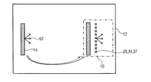
第1の放射面28の全体に亘って均一であって直接光方向32周辺に狭いピーク30がある輝度プロファイルLdirectで、第1の放射面28から同様に発せられる直接光を放射する直接光源の機能の結果として、以下のようになる。1)直接光方向32は、第1の放射面28の全体において実質的に一定であり、2)発散は小さく、3)発散は、第1の放射面28の全体において実質的に一定である。「小さく」および「実質的に」の程度については、以下により詳細に説明する。いずれの場合でも、図4を参照すると、これらの制約に従う直接光源12により発せられる直接光により、直接光源およびその第1の放射面28を見ている観察者38は、輝点40を狭い可視円錐角42で見ており、輝点は、両眼輻輳、遠近調節および運動視差の深さキュー(motion parallax depth cue)に関して、無限の距離で知覚される。換言すれば、観察者38は、第1の放射面28を見るときに、輝点40を見ており、観察者が光放射面に対して動くと、輝点40は、無限遠の位置にある対象物から生じているかのように、第1の放射面28に対して動く。 A direct light source that emits direct light similarly emitted from the first emitting surface 28 with a luminance profile L direct that is uniform over the entire first emitting surface 28 and has a narrow peak 30 around the direct light direction 32. As a result of the function: 1) The direct light direction 32 is substantially constant throughout the first radiation surface 28, 2) the divergence is small, and 3) the divergence is substantially constant throughout the first radiation surface 28. . The degree of “small” and “substantially” will be described in more detail below. In any case, referring to FIG. 4, the direct light emitted by the direct light source 12 subject to these constraints allows the observer 38 looking at the direct light source and its first emitting surface 28 to see the bright spot 40 narrowly visible. Looking at cone angle 42, the bright spot is perceived at infinite distance with respect to binocular vergence, accommodation and motion parallax depth cue. In other words, the observer 38 looks at the bright spot 40 when viewing the first emission surface 28, and when the observer moves with respect to the light emission plane, the bright spot 40 is positioned at infinity. It moves relative to the first emitting surface 28 as if it originated from an object.

第1の放射面28で直接光源12により発せられた光の輝度プロファイルによる上述の均一性およびピークの尖鋭性に関して従うべき上述の制約を定義するため、狭いピークの形成に寄与する一方の内側直接光成分と、残余の背景を形成することになる周辺のより発散性のある他方の成分とを、区別し得るものであり、輝度プロファイルのとりうる変化を、両眼輻輳および運動視差の深さキューに関し、より狭い領域とより広い領域(すなわち、第1の放射面28のほぼ全領域)とで区別し得る。その制約について、以下に定義する。   In order to define the above constraints to be followed with respect to the above uniformity and peak sharpness due to the intensity profile of light emitted directly by the light source 12 at the first emitting surface 28, one inner direct that contributes to the formation of a narrow peak. It can distinguish the light component from the other more divergent component that will form the rest of the background, and the possible changes in the luminance profile to the depth of binocular convergence and motion parallax With respect to cues, a distinction can be made between a narrower area and a wider area (ie, almost the entire area of the first radiation surface 28). The restrictions are defined below.

特に、直接光源12は、第1の放射面28の全体に亘り均一な強度で、放射面の法線zに対して単一の所定方向32に光を発し、発散円錐が非常に低く、好ましくは円形対称で、このような発散円錐の外側の背景も低く、発散と背景の両方ともパネル全体に亘って均一になっている。これについて、Ldirect(x,y,θ,φ)は、暗環境で直接光源から発せられた直接光の輝度を示すこととする。ここで、暗環境とは、直接光源外部で光が一切発せられたり反射したりすることがないものであり、x、y、θおよびφは、既に定義したとおりである。なお、輝度を、空間および角座標の関数で表すには、検出器の実際の角分解能および光源からの距離を説明すべきであり、これにより、検出可能な空間分解能が決まる。本発明に関し、角分解能は0.07°と想定されており、これは、典型的な裸眼の角分解能に近似するものである。空間分解能は1mmと想定されており、これは、観察距離が約1mであることに対応する。したがって、本発明に関連して説明した輝度プロファイルに関する全ての制約は、上述の分解能となることが意図されている。これは、高い角周波数または空間周波数で(すなわち、高い角分解能および/または近接した距離で)最終的に生じる変動は、本発明の目的からして関係がないということである。制約は以下のようになる。 In particular, the direct light source 12 emits light in a single predetermined direction 32 with respect to the normal z of the radiating surface with a uniform intensity across the first radiating surface 28 and has a very low divergence cone, preferably Is circularly symmetric, the background outside such a divergence cone is also low, and both the divergence and background are uniform across the panel. In this regard, L direct (x, y, θ, φ) represents the luminance of direct light emitted directly from a light source in a dark environment. Here, the dark environment means that no light is emitted or reflected directly outside the light source, and x, y, θ, and φ are as already defined. In order to express the brightness as a function of space and angular coordinates, the actual angular resolution of the detector and the distance from the light source should be described, and this determines the spatial resolution that can be detected. For the present invention, the angular resolution is assumed to be 0.07 °, which approximates the typical naked eye angular resolution. The spatial resolution is assumed to be 1 mm, which corresponds to an observation distance of about 1 m. Therefore, all constraints on the luminance profile described in connection with the present invention are intended to be the resolution described above. This means that variations that eventually occur at high angular or spatial frequencies (ie, at high angular resolution and / or close distance) are irrelevant for purposes of the present invention. The constraints are as follows:

方向32から遠い。すなわち、極角θ>θHWHM。ここで、θHWHMは、平均極角分布のHWHM(半値半幅)であり、これは、光放射面における全ての位置(x,y)および全ての方位方向φについての輝度プロファイルLdirectの平均であり、輝度プロファイルLdirectは、全ての位置および角度でのLdirectの絶対最大値の10%を下回り、好ましくは1%、より好ましくは0.1%を下回る。 Far from direction 32. That is, polar angle θ> θ HWHM . Here, θ HWHM is the average polar angle distribution HWHM (half width at half maximum), which is the average of the luminance profiles L direct for all positions (x, y) and all azimuth directions φ on the light emitting surface. Yes , the luminance profile L direct is below 10% of the absolute maximum of L direct at all positions and angles, preferably below 1%, more preferably below 0.1%.

方向32に近い。すなわち、極角θ≦θHWHM。ここで、輝度プロファイルLdirectは、方位座標φに弱く依存する。例えば、各位置(x,y)について、外側でLdirectが最大値の10%を下回る領域θ,φは、実質的に底面が円形の円錐となり、これにより、観察者は、光源を方向32に見たときに、円形の点を知覚可能となる。定量的には、同量の合計の半分に規格化された上記領域の最大極角と最小極角との差は、サンプルにおけるあらゆる位置について、0.5を下回り、好ましくは0.2を、より好ましくは0.1を下回ることになる。
ここで、θHWHM≦2.5°であり、好ましくはθHWHM≦1.5°、より好ましくはθHWHM≦0.5°である。
数式では、以下のようになる。

Figure 0006592154
および
Figure 0006592154
ここで、
Aは、第1の放射面28の面積、
θHWHM≦2.5°であり、好ましくはθHWHM≦1.5°、より好ましくはθHWHM≦0.5°であり、
k=0.1であり、好ましくはk=0.01、より好ましくはk=0.001であり、
h=0.5であり、好ましくはh=0.2、より好ましくはh=0.1である。
ここで、以下の定義が真として成り立つ。
Figure 0006592154
Close to direction 32. That is, polar angle θ ≦ θ HWHM . Here, the luminance profile L direct is weakly dependent on the azimuth coordinate φ. For example, for each position (x, y), the regions θ, φ outside which L direct is less than 10% of the maximum value are substantially cones with a circular bottom surface, which allows the observer to point the light source in direction 32. It becomes possible to perceive a circular point when viewed. Quantitatively, the difference between the maximum and minimum polar angles of the region, normalized to half the sum of the same amount, is less than 0.5, preferably less than 0.2, for every position in the sample. More preferably, it will be less than 0.1.
Here, θ HWHM ≦ 2.5 °, preferably θ HWHM ≦ 1.5 °, and more preferably θ HWHM ≦ 0.5 °.
The formula is as follows.
Figure 0006592154
and
Figure 0006592154
here,
A is the area of the first radiation surface 28,
θ HWHM ≦ 2.5 °, preferably θ HWHM ≦ 1.5 °, more preferably θ HWHM ≦ 0.5 °,
k = 0.1, preferably k = 0.01, more preferably k = 0.001,
h = 0.5, preferably h = 0.2, more preferably h = 0.1.
Here, the following definition holds true.
Figure 0006592154

方向32から遠く離れた残りの直接光の背景の均一性にさらに注目すると、Ldirectについての要件は、極角θが3θHWHMより大きい場合に、空間振幅変動が最小となることを示している。例えば、上記輝度空間変動の標準偏差と輝度平均値との比は、あらゆる10mm径空間円形領域内で光放射面の少なくとも90%について、0.3の値を超えず、好ましくは0.1の値を超えず、光放射面の少なくとも90%の全体内であらゆる既定の方位角φおよび3θHWHMより大きいあらゆる既定の極角θについて、0.4の値を超えず、好ましくは0.3の値を超えず、より好ましくは0.2の値を超えなくともよい。 Further focusing on the uniformity of the background of the remaining direct light far from direction 32, the requirement for L direct indicates that the spatial amplitude variation is minimized when the polar angle θ is greater than 3θ HWHM . . For example, the ratio between the standard deviation of the luminance space variation and the luminance average value does not exceed a value of 0.3, preferably 0.1, for at least 90% of the light emitting surface in any 10 mm diameter circular space region. not exceed the value, for at least 90% and any default azimuth φ in the entire 3q HWHM larger every predetermined polar angle of the light emitting surface theta, it does not exceed the value of 0.4, preferably of 0.3 The value may not be exceeded, more preferably the value of 0.2 may not be exceeded.

方向32に近接した直接光の均一性が考慮される限り、5cm径の空間領域内でθHWHMの20%より大きな標準偏差で、好ましくは10cm径、より好ましくは20cm径で、Ldirectについての要件は、(極大)最大輝度となる(局所的)極角内の空間変動を示すものではなく、光放射面の全体の少なくとも90%の全体内で、標準偏差がθHWHMより大きい(極大)最大輝度となる(局所的)極角内の空間変動を示すものではない。ここでθHWHM≦2.5°、好ましくはθHWHM≦1.5°、最も好ましくはθHWHM≦0.5°である。
数式で表現すると、上述の制約は、以下のように定式化される。

Figure 0006592154
As long as the uniformity of the direct light close to the direction 32 is considered, a large standard deviation of 20% theta HWHM in the space area of 5cm diameter, preferably 10cm diameter, more preferably 20cm diameter, for L direct The requirement does not indicate a spatial variation within the (local) polar angle that results in the (maximum) maximum brightness, and the standard deviation is greater than θ HWHHM within at least 90% of the entire light emitting surface (maximum). It does not indicate the spatial variation within the (local) polar angle that gives the maximum brightness. Here, θ HWHM ≦ 2.5 °, preferably θ HWHM ≦ 1.5 °, and most preferably θ HWHM ≦ 0.5 °.
Expressed in mathematical terms, the above constraints are formulated as follows.
Figure 0006592154

要約すると、上記の制約により、直接光方向32から充分に離れた極角については、Ldirectが相当に弱く、均一となる一方、直接光方向32に近接した極角については、Ldirectは方位座標に弱く依存し、同方向にピークを持つ、すなわち、任意の(x,y)∈Aについてθ=0、少なくとも実質的に円形の点40が確実に現れることが、保障される。上述のように、これらの制約により、観察者38は、2・θHWHMと同じかまたは同様の全幅角サイズ42で、弱く均一な背景に囲まれた、明るく円形の点40のみを見るようになることが保障される。 In summary, due to the above constraints, L direct is considerably weak and uniform for polar angles far away from direct light direction 32, while L direct is azimuth for polar angles close to direct light direction 32. It is guaranteed to depend reliably on the coordinates and have a peak in the same direction, ie, for any (x, y) εA, θ = 0, and at least a substantially circular point 40 to appear reliably. As mentioned above, these constraints allow the observer 38 to see only bright and circular points 40 with a full width angle size 42 equal to or similar to 2 · θ HWHHM and surrounded by a weak and uniform background. It is guaranteed to become.

ある実施形態では、直接光源は、かなり明るい環境内で動作するときにも、背景が確実に暗く均一となるように構成される。すなわち、周辺光は、背景輝度レベルおよび均一性について、第1の放射面28の形成を損なう程には、反射されたり、後方散乱されたりしない。実際に、第1の放射面28は、発光するだけでなく、例えば拡散光発生器10(その下流に位置する場合)からおよび/または周辺から受光する。例えば、人工照明装置20が完全に白い部屋を照明する理想的な場合には、直接光源から発せられた全光束は、直接光源自体に戻ることになる。   In some embodiments, the direct light source is configured to ensure that the background is dark and uniform, even when operating in a fairly bright environment. That is, the ambient light is not reflected or backscattered to the extent that it impairs the formation of the first radiating surface 28 in terms of background luminance level and uniformity. In fact, the first emitting surface 28 not only emits light but also receives light from, for example, the diffuse light generator 10 (if located downstream) and / or from the periphery. For example, in the ideal case where the artificial lighting device 20 illuminates a completely white room, the total luminous flux emitted from the direct light source returns directly to the light source itself.

上記要件は、換言すれば、直接光源12がオフであるときに、拡散した外側の照明下で外観が暗く均一であるという、第1の放射面28の要件である。特に、本実施形態では、直接光源12は、第1の放射面28の全反射(平均)係数がη≦0.4、好ましくはη≦0.2、より好ましくはη≦0.1、さらに好ましくは、η≦0.04となるように、構成されている。ここで、全反射係数ηは、試料の面が境界となった半球内の全角度で反射した光束と、同一の幾何学的空間的測定条件において完全反射拡散体で反射した光束との比として定義される。これは、例えば、サンプルに均一な照度(lux/m)を提供するD65標準光源による拡散照明下でなされる。 In other words, the above requirement is a requirement of the first emitting surface 28 that the appearance is dark and uniform under diffused outer illumination when the direct light source 12 is off. In particular, in the present embodiment, the direct light source 12 has a total reflection (average) coefficient of the first radiation surface 28 of η r ≦ 0.4, preferably η r ≦ 0.2, more preferably η r ≦ 0. 1, and more preferably, η r ≦ 0.04. Here, the total reflection coefficient η r is the ratio of the light beam reflected at all angles in the hemisphere bounded by the sample surface to the light beam reflected by the perfect reflection diffuser under the same geometric spatial measurement conditions. Is defined as This is done, for example, under diffuse illumination with a D65 standard light source that provides uniform illuminance (lux / m) to the sample.

さらに別の実施形態では、方向32から遠く離れた第1の放射面28の外観が暗く均一であるという要件は、更に厳しくなっている。これは、絶対輝度値とその変動の両方に関わるため、反射光の上限が直接光により制限されることが要請されるためである。さらに正確には、本実施形態は、第1の放射面28が、背景光について、受動光学素子としても、同じ特性を保つことを保障している。すなわち、かなり明るい環境内で動作する場合に、反射および拡散する光についても、保障されている。換言すると、直接光源12は、放射円錐30の外側での観測におけるあらゆる極角について、また、強い周辺光があるときにも、暗く均一な外観を保障している。   In yet another embodiment, the requirement that the appearance of the first emitting surface 28 far away from the direction 32 is dark and uniform is even more stringent. This is because the upper limit of the reflected light is required to be limited by direct light because it relates to both the absolute luminance value and its variation. More precisely, this embodiment ensures that the first radiating surface 28 maintains the same characteristics for the background light as a passive optical element. That is, light that is reflected and diffused when operating in a fairly bright environment is also guaranteed. In other words, the direct light source 12 ensures a dark and uniform appearance for every polar angle in the observation outside the radiation cone 30 and also in the presence of strong ambient light.

この要件は、換言すると、拡散光発生器10が人工照明装置から取り外されて、直接光源12がオフで、第1の放射面28が第1の放射面28に当たる外部の拡散光により照明され、オンになっているときに直接光源12自体によって第1の放射面に当たる照度の平均に等しい一定の照度となる場合、外側の拡散光が、光放射面により反射または後方散乱され、あらゆる位置でLdirectより弱く、あらゆる角度で第1の放射面28の少なくとも90%となる、第1の放射面28での反射率輝度プロファイルLを生じるように、直接光源12が構成されるべきということになる。ここで、Lは、任意の10mm径の空間円形領域内での振幅の標準偏差が、第1の放射面28の少なくとも90%内である対応するLdirectの標準偏差よりも小さくなっている。
数式におけるLの「弱さ」および「均一性」についての上述の制約は、以下のように読み取ることができる。

Figure 0006592154
全ての(x,y)∈A10mm(X,Y),全てのφ∈[0;2π[,および全てのθ∈[0,π]について
ここで、(X,Y)∈A90%について、
90%は、第1の放射面28の全領域の90%を占める部分を示し、この部分は単連結であってもそうでなくともよく、A10mmは、A内の(X,Y)での10mm径の任意の
Figure 0006592154
This requirement is, in other words, the diffused light generator 10 is removed from the artificial lighting device, the direct light source 12 is off, and the first radiating surface 28 is illuminated by external diffused light that strikes the first radiating surface 28, When the light source 12 itself has a constant illuminance equal to the average of the illuminance striking the first radiation surface when turned on, the outer diffused light is reflected or backscattered by the light radiation surface and is L at every position. weaker than direct, at any angle is at least 90% of the first radiation surface 28, to produce the reflectance intensity profile L R of the first radiation surface 28, the fact that should a direct light source 12 is constituted Become. Here, LR is smaller than the standard deviation of the corresponding L direct in which the standard deviation of the amplitude in an arbitrary 10 mm-diameter spatial circular region is within at least 90% of the first radiation surface 28. .
Above limitations of "weakness" and "uniformity" of L R in formula can be read as follows.
Figure 0006592154
For all (x, y) εA 10 mm (X, Y), for all φε [0; 2π [, and for all θε [0, π], where (X, Y) εA 90 % ,
A 90 % indicates a portion that occupies 90% of the entire area of the first radiation surface 28, and this portion may or may not be simply connected, and A 10 mm is (X, Y) within A Any of 10mm diameter at
Figure 0006592154

その他の実施形態では、第1の放射面28での直接光源12により発せられた光の狭いピーク30の方向および幅における空間変動についての制約は、異なる形に定式化される。すなわち、輝度プロファイルLdirectは、第1の放射面28の全体における最大値の局所方向の分布範囲が2°未満であることを示し、全ての方位角に亘るLdirectの局所平均極角プロファイルのHWHMの第1の放射面28の全体における平均値が、5°未満である。数式により表現すると、これは以下のようになる。

Figure 0006592154
In other embodiments, constraints on spatial variations in the direction and width of the narrow peak 30 of light emitted by the direct light source 12 at the first emitting surface 28 are formulated differently. That is, the luminance profile L direct indicates that the distribution range in the local direction of the maximum value in the entire first radiation surface 28 is less than 2 °, and the local average polar angle profile of L direct over all azimuth angles. The average value of the entire first radiation surface 28 of HWHM is less than 5 °. This is expressed by the following mathematical formula.
Figure 0006592154

もちろん、輝度プロファイルの最大値の方向の分布は、放射対称ベクトル場とは異なるべきであるので、直接光内の物体により投射される影は、収束方向に揃わない。これは、図28、図30および図31の装置の場合である。より正確には、直接光源により照明されて、方向32に沿って互いに平行に配列された複数の長尺物は、有限距離で局所化された光源による照明に典型的な外側に放射対称に向く作用により特徴づけられるものではない、複数の影を、任意の平面に落とすように、直接光源は構成されている。この目的を達成するために、狭いピーク30の方向の空間変動は、上述の制限内で発生し得るものであり、不規則またはランダムである。   Of course, since the distribution in the direction of the maximum value of the luminance profile should be different from the radial symmetric vector field, the shadow directly projected by the object in the light is not aligned in the convergence direction. This is the case for the devices of FIGS. 28, 30 and 31. More precisely, a plurality of elongate objects illuminated by a direct light source and arranged parallel to each other along direction 32 are directed radially outwardly typical of illumination by a light source localized at a finite distance. The direct light source is configured to drop a plurality of shadows, which are not characterized by action, onto an arbitrary plane. To achieve this goal, spatial variations in the direction of the narrow peak 30 can occur within the limits described above and are irregular or random.

直接光源12と拡散光発生器10とを、上述のいずれかの方法で組み合わせることにより、人工照明装置20は、明るく、好ましくは、空を模して拡散光発生器10から発せられる青みがかった背景を提供するとともに、直接光源12から発せられて輝点40となる光は、より暖かいCCTとなる。第1の放射面28の前を歩くと、太陽が実際の窓を横切るように、この点40は面に沿って横切って行く。   By combining the direct light source 12 and the diffused light generator 10 by any one of the methods described above, the artificial lighting device 20 is bright and preferably has a bluish background emitted from the diffused light generator 10 imitating the sky. In addition, light emitted directly from the light source 12 to become the bright spot 40 becomes a warmer CCT. As you walk in front of the first radiating surface 28, this point 40 traverses along the surface so that the sun crosses the actual window.

特に、直接光源12の直接光が観察者38の両眼で一旦視認されると、観察者38は、無限の距離に輝点40を知覚する。実際に、輝度プロファイルLdirectの概略的特徴によると、図1に示すように、2つの網膜上に等しく位置したそれぞれの輝点を両眼が平行に知覚するようになっている。これは、装置20が深い奥行き感を提供することを保障する条件である。Ldirectがx,yおよびφから独立し、θ>θについて仮想的に0で、θ<θについて定数値をとる場合に、これらの条件は理想的に保障され、ここで、θは、例えば3°、より好ましくは1°、さらに好ましくは0.5°である。しかしながら、この理想的な領域とある程度の差異は、可能な制約の上述の例に示すように、明らかに許容可能である。許容される差異量は、視覚の不一致の不在または少なくとも有限距離で支配的な奥行き感をもたらす不一致の不在をもたらすように、上述の大きな(仮想的には無限の)奥行き感を保障する必要によって主として決定される。この条件は、可能な制約についての上記の例により保障される。 In particular, once the direct light of the direct light source 12 is visually recognized by both eyes of the observer 38, the observer 38 perceives the bright spot 40 at an infinite distance. Actually, according to the general feature of the luminance profile L direct , as shown in FIG. 1, both eyes perceive the luminescent spots equally positioned on the two retinas in parallel. This is a condition that ensures that the device 20 provides a deep sense of depth. These conditions are ideally guaranteed when L direct is independent of x, y and φ and is virtually zero for θ> θ 0 and constant values for θ <θ 0 , where θ 0 Is, for example, 3 °, more preferably 1 °, and even more preferably 0.5 °. However, some differences from this ideal region are clearly acceptable, as shown in the above example of possible constraints. The amount of difference allowed depends on the need to ensure a large (virtually infinite) sense of depth as described above, so as to result in the absence of visual discrepancies or the absence of discrepancies that at least give a dominant sense of depth at a finite distance. Mainly determined. This condition is guaranteed by the above example for possible constraints.

有限距離での直接光源の実像の視認性は、換言すれば、奥行き効果を妨げないようにある程度の制限内とされた輝度プロファイルLdirectへの所定の寄与である。すなわち、Ldirectに対する上述の理想的な制約が満たされた場合、直接光源12は視認不能であり、可視の物体は輝点40のみである。許容可能な差異を明瞭にするためには、角周波数は、眼の分解能、すなわち0.07°により課される制限よりも大きくないという条件で、観察者38は、色分布と同様、物体の輝度上の非常に弱い空間変動を容易に知覚するものと説明されることになる。これは、観察者38の装置20からの最短距離を1mと想定して、例えば、直接光源12の空間変動は、約1mm未満のスケールで生じるとすれば許容可能であることを意味する。大きなスケールでのこのような変動の発生は、少なくともθ>θについて発生する場合、観察者の眼で容易に特定可能である。なお、ここで、視覚は飽和していない。 In other words, the visibility of the real image of the direct light source at a finite distance is a predetermined contribution to the luminance profile L direct that is within some limits so as not to disturb the depth effect. That is, when the above-described ideal constraint on L direct is satisfied, the direct light source 12 is not visible and the visible object is only the bright spot 40. In order to clarify the acceptable difference, the observer 38, as well as the color distribution, is allowed to observe the object on the condition that the angular frequency is not greater than the limit imposed by the eye resolution, ie 0.07 °. It will be explained that a very weak spatial variation in luminance is easily perceived. This means that assuming that the shortest distance of the observer 38 from the apparatus 20 is 1 m, for example, if the spatial variation of the direct light source 12 occurs on a scale of less than about 1 mm, it is acceptable. The occurrence of such fluctuations on a large scale can be easily identified by the observer's eye when it occurs at least for θ> θ 0 . Here, vision is not saturated.

なお、最大値の10%の背景輝度は、非常に高い数値であるが、ある条件下で許容可能となりうる。条件は、まさに日の出と日没における空および太陽の照明を再現するためのもので、すなわち、太陽の輝度が、空の輝度に対して、日中と同じようには高くない時である。   Note that a background brightness of 10% of the maximum value is a very high value, but may be acceptable under certain conditions. The condition is just to reproduce the sky and solar lighting at sunrise and sunset, i.e. when the brightness of the sun is not as high as that of the day with respect to the brightness of the sky.

略述した制約のいずれかにて、これらの制約が図28に示す設定を満たさないことは明らかである。これは、光源902は、Ldirectの空間的均一性が、外側に放射対称に向く作用により特徴づけられる影を確実に妨げるように、パネル906から極めて離れたところに配置されるべきであるためである。さらに、図29の設定は、ドーム集光器を伴うLEDアレイを示し、制約を満たさない。これは、輝度のHWHMは、必要とされるよりも1オーダー大きいため、および結果としての輝度が、LEDアレイのピッチにより1mmよりもかなり大きいスケール上で、HWHM円錐放射角について強い空間変動を示すためである。図29の設定のLEDが接続されていなければ、所望の仕様も得られないことに注目すべきである。例えば、TIR光学集光器で、より一般的には、例えば、複合放物面集光器(CPC)デバイス等、非結像光学の分野で用いられる標準的な集光器のうちの任意のものによる。実際に、所望の低い発散がかなり大きくなることが保障されるように、これらの光学素子がとるべき横寸法は、すなわち、現在入手可能な一般的照明LEDチップの最小寸法が約1mmであることと、一般的LEDライトと光学素子との結合の必要について考慮する場合、数センチである。このことは、少なくとも光放射面に近接して、すなわち、光放射面から1m離れた観察者について、例えば、観察者の眼は、光学素子の各々の内側の輝点40を見る、すなわち、例えば、1°の完全な発散で1mの距離で輝点が2cmなどのように、輝点の寸法は光学素子の寸法よりも小さいことを意味する。そこから(上記参照)短い距離のこのような低発散非結像光学素子を見ている観察者は、あらゆる円形の点の真像を知覚することができず、さらには、あらゆる無限遠焦点深度を経験することができない。これは、このような非結像光学素子により生じた輝度は、真に均一(すなわち、シフト不変)ではなく、方位角について不変でもないからである。結果として、両眼は2つの像を捉える。これらの像は、光学素子と接続された放射光源(例えばLED)が円形であって一様でなくとも、(i)が一般には円形ではない。両眼が異なる像を知覚するという事実は、平行方向に向いた両眼が従うべきものについては、非常に好ましくない。一方、この環境下で、両眼にとって真に等しく見えるものに、すなわち有限距離の光源物体に、両眼が焦点を合わせることははるかに容易である。このことにより、太陽の外観の丸みだけでなく、無限の奥行き感をも妨げる。
言及した考え方は、以下の制約がLEDにより満たされる場合には、直接光源12のさらに別の実施形態が図29の文脈で解釈され得ることを示唆している。
It is clear that for any of the constraints outlined, these constraints do not meet the settings shown in FIG. This is because the light source 902 should be placed very far from the panel 906 to ensure that the spatial uniformity of L direct prevents shadows characterized by outwardly radiating effects. It is. Furthermore, the setup of FIG. 29 shows an LED array with a dome concentrator and does not meet the constraints. This is because the luminance HWHM is one order of magnitude greater than needed, and on the scale where the resulting luminance is significantly greater than 1 mm due to the pitch of the LED array, it shows a strong spatial variation for the HWHM cone emission angle. Because. It should be noted that the desired specification cannot be obtained unless the LED set in FIG. 29 is connected. For example, a TIR optical concentrator, more generally any of the standard concentrators used in the field of non-imaging optics, such as, for example, a compound parabolic concentrator (CPC) device Depends on things. In fact, to ensure that the desired low divergence is quite large, the lateral dimension that these optical elements should take, i.e., the minimum dimension of currently available general illumination LED chips is about 1 mm. In consideration of the necessity of coupling a general LED light and an optical element, it is several centimeters. This means that for an observer at least close to the light emitting surface, i.e. 1 meter away from the light emitting surface, for example, the eyes of the observer see the bright spot 40 inside each of the optical elements, i.e. It means that the size of the bright spot is smaller than that of the optical element, such as 2 cm at a distance of 1 m with a complete divergence of 1 °. From there (see above) an observer looking at such a low divergence non-imaging optic at a short distance cannot perceive the true image of any circular point, and at any infinity depth of focus. Can not experience. This is because the brightness produced by such a non-imaging optical element is not truly uniform (ie, shift invariant) and is not invariant with respect to azimuth. As a result, both eyes capture two images. These images are generally not circular, even though the radiation source (eg, LED) connected to the optical element is circular and not uniform. The fact that both eyes perceive different images is very unfavorable for what both eyes facing in a parallel direction should follow. On the other hand, in this environment, it is much easier for both eyes to focus on what appears to be truly equal to both eyes, ie, a light source object of a finite distance. This hinders not only the roundness of the sun's appearance but also the infinite depth.
The idea mentioned suggests that yet another embodiment of the direct light source 12 can be interpreted in the context of FIG. 29 if the following constraints are met by the LED.

(i)放射方向に垂直な方向の各LED(レンズドームを含む)の大きさは、実質的に小さくなり得る。すなわち、3mm、好ましくは1mm、最も好ましくは0.5mmにまで低減し得る。このことは、オンおよびオフの両モードにおいて、均一性の制約に従うことになる。   (I) The size of each LED (including the lens dome) in the direction perpendicular to the radiation direction can be substantially reduced. That is, it can be reduced to 3 mm, preferably 1 mm, most preferably 0.5 mm. This obeys uniformity constraints in both on and off modes.

(ii)LED発光器の大きさ、すなわち蛍光体または色素帯の大きさ、すなわち、その線形寸法は、現在入手可能な最小の一般照明LEDについて通例約1mmであり、これとドームレンズの焦点距離との比は、1°から5°の範囲の発散を保障するためには、約1/10から1/50となるべきである。例えば、1°の発散を考慮して、焦点距離を1mmとし、ドーム径が、最大のスループットを保障するのに必要な焦点距離と同等になると想定して、LED発光器の寸法が、結局、20μm未満となる。   (Ii) The size of the LED emitter, i.e. the size of the phosphor or pigment band, i.e. its linear dimension, is typically about 1 mm for the smallest general illumination LED currently available, and this is the focal length of the dome lens. The ratio should be about 1/10 to 1/50 to ensure divergence in the range of 1 ° to 5 °. For example, considering the divergence of 1 °, assuming that the focal length is 1 mm and the dome diameter is equivalent to the focal length necessary to ensure maximum throughput, the dimensions of the LED emitter are It becomes less than 20 μm.

(iii)さらに、各LED発光器および対応するドームは、微小な暗箱に実装されている。この暗箱は、LED発光器に帰る周辺光から離れたドームレンズを横切る周辺光を実質的に全て吸収する吸収体により被覆されるべきである。この場合、LEDマトリクスは、外部の光により照明された場合に暗くなり得る。さらに、レンズドームと組み合わされるLED周辺から(例えば、LEDボードから)の散乱光を防ぐことになる。   (Iii) Furthermore, each LED light emitter and the corresponding dome are mounted in a minute dark box. This dark box should be covered with an absorber that absorbs substantially all of the ambient light across the dome lens away from the ambient light returning to the LED emitter. In this case, the LED matrix can become dark when illuminated by external light. Furthermore, scattered light from the periphery of the LED combined with the lens dome (eg, from the LED board) will be prevented.

(iv)LEDドームレンズは、周辺から戻る周辺光の反射を最小化するために、反射防止コーティングされ得る。   (Iv) The LED dome lens may be anti-reflective coated to minimize the reflection of ambient light returning from the periphery.

上記内容を要約すると、直接光源12は、図5を参照して以下により詳細に説明する特別な構造のLEDの2次元アレイを備えるものと解釈され得る。特に、各LED44は、蛍光体および/または色素などを含む発光ダイオードなどの発光体46と、コリメータとを備える。コリメータは、例えばドームレンズ48であり、ドームは、発光体46からドームの焦点距離と実質的に等しい距離49をとって配置される。発光体46は、方位座標から独立した輝度分布が得られやすくなるように、方向32に垂直な平面内に円形の断面を有することが好ましい。ドーム48における窓52の上流側を通じて発光体46が光を発し、下流端部にて光コリメートレンズ面54が形成されており、窓以外のドームの全内面は、56として示す微小暗箱を形成するように、光吸収体により被覆される。ここで述べたように、面54には、反射防止コーティングが施されてもよく、発光体46の発光帯の横寸法または幅、すなわち58は、充分に小さくする必要があり、一方の幅58と他方の長さ49との比が1/10未満となる必要があり、好ましくは1/20未満、最も好ましくは1/50未満となるとよい。さらに、ピッチ50は、3mm未満となる必要があり、好ましくは1mm未満、最も好ましくは0.5mm未満になるとよい。上述のように、LED44は、六角形状になるように密に充填され得る。LED44のアレイは、第1の放射面28と同じ面積を覆うことになる。   In summary, the direct light source 12 can be interpreted as comprising a two-dimensional array of specially structured LEDs that will be described in more detail below with reference to FIG. In particular, each LED 44 includes a light emitter 46 such as a light emitting diode including a phosphor and / or a dye, and a collimator. The collimator is, for example, a dome lens 48, and the dome is disposed at a distance 49 substantially equal to the focal length of the dome from the light emitter 46. The light emitter 46 preferably has a circular cross section in a plane perpendicular to the direction 32 so that a luminance distribution independent of the azimuth coordinates can be easily obtained. The light emitter 46 emits light through the upstream side of the window 52 in the dome 48, and a light collimating lens surface 54 is formed at the downstream end, and the entire inner surface of the dome other than the window forms a micro dark box indicated as 56. Thus, it is coated with a light absorber. As described herein, the surface 54 may be provided with an anti-reflective coating, and the lateral dimension or width of the light emission band of the light emitter 46, ie, 58, should be sufficiently small, while one width 58 And the other length 49 must be less than 1/10, preferably less than 1/20, and most preferably less than 1/50. Furthermore, the pitch 50 needs to be less than 3 mm, preferably less than 1 mm, and most preferably less than 0.5 mm. As described above, the LEDs 44 can be densely packed into a hexagonal shape. The array of LEDs 44 will cover the same area as the first emitting surface 28.

もちろん、図1の光放射デバイス/コリメータの対を、図5および図6に示すような個々のLED素子44に実装することは、必ずしも必要ではない。これは、以下の実施形態のために説明されている。   Of course, it is not necessary to mount the light emitting device / collimator pair of FIG. 1 on individual LED elements 44 as shown in FIGS. This has been described for the following embodiments.

図7は、例えば、直接光源12を、主要光62を発するように構成された第1の光放射デバイス60と、コリメートレンズ64の形をとるコリメータとを備えるものとして示し、コリメータは、下流側に、第1の光放射デバイスから、直接光方向32と一致する光軸68に沿って焦点距離66で配置されている。例えば、図28の実施形態を特徴づけるLEDドームレンズの場合のような標準的な照明デバイスとは異なり、本実施形態では、レンズ64は、結像光学素子であってもよい。これは、所定の光学レイアウトパラメータ(系の開口数、レンズと放射デバイスとの距離、焦点距離と横寸法との比など)が、レンズに、第1の光放射デバイス60の像を無限遠において確実に形成させ得るという意味においてである。   FIG. 7 shows, for example, the direct light source 12 as comprising a first light emitting device 60 configured to emit primary light 62 and a collimator in the form of a collimating lens 64, the collimator being downstream And from the first light emitting device at a focal length 66 along an optical axis 68 that coincides directly with the light direction 32. For example, unlike a standard lighting device, such as in the case of an LED dome lens that characterizes the embodiment of FIG. 28, in this embodiment, the lens 64 may be an imaging optic. This is because predetermined optical layout parameters (such as the numerical aperture of the system, the distance between the lens and the radiating device, the ratio of the focal length to the lateral dimension, etc.) allow the lens to image the first light emitting device 60 at infinity. In the sense that it can be reliably formed.

製造コストの削減、および構造的な小型化を図るために、コリメートレンズ64は、フレネルレンズであってもよい。それにより、第1の光放射デバイス60は、LEDとして実装され得る。   The collimating lens 64 may be a Fresnel lens in order to reduce manufacturing costs and reduce the size of the structure. Thereby, the first light emitting device 60 may be implemented as an LED.

なお、図7の説明を参照し、光軸68は、コリメートレンズ64の光軸と一致してもよく、それとは斜行していてもよく、ここで、光軸68は、コリメートレンズ64の主平面(主平面が2つの場合、第1の光放射デバイス60により近接して位置する面)とレンズ64の光軸との交点61を、第1の光放射デバイス60の発光帯の重心とを結ぶ線により定義されている。フレネルレンズ64の場合、フレネルレンズ64は、第1の放射面28と平行に配列されてもよく、以下に概要を示すように、面内にあってもよい。他のコリメートレンズ64の場合、主平面について同様のことが適用され得る。いずれにせよ、レンズ64の開口が、第1の放射面28と同じ広さの領域を覆う。
第1の光放射デバイス60は、無限遠に合焦した観察者の眼において輝点40が円形状になるように、円形の開口を有してもよい。
Referring to the description of FIG. 7, the optical axis 68 may coincide with the optical axis of the collimating lens 64, and may be skewed with the optical axis 68. The intersection 61 between the principal plane (the surface located closer to the first light emitting device 60 when there are two principal planes) and the optical axis of the lens 64 is defined as the center of gravity of the emission band of the first light emitting device 60. Is defined by the line connecting In the case of the Fresnel lens 64, the Fresnel lens 64 may be arranged in parallel with the first radiation surface 28 and may be in-plane as outlined below. For other collimating lenses 64, the same can be applied for the main plane. In any case, the opening of the lens 64 covers an area having the same area as the first radiation surface 28.
The first light emitting device 60 may have a circular opening so that the bright spot 40 has a circular shape in the eyes of the observer focused at infinity.

図7にも示すように、図7の直接光源12は、第1の光放射デバイス60を格納する暗箱70を形成するとともにコリメートレンズ64が配置される開口を有する吸収体を、さらに備え得る。暗箱70の内面72は、可視光の吸収係数が70%より高く、好ましくは90%、より好ましくは95%より高い光吸収材で、形成されている。これにより、反射率輝度角度プロファイルの制約に従う結果となる。   As shown also in FIG. 7, the direct light source 12 of FIG. 7 may further include an absorber that forms a dark box 70 that houses the first light emitting device 60 and has an opening in which the collimating lens 64 is disposed. The inner surface 72 of the dark box 70 is formed of a light absorbing material having a visible light absorption coefficient higher than 70%, preferably higher than 90%, more preferably higher than 95%. This results in compliance with the constraints of the reflectance luminance angle profile.

なお、図7は、多くの特徴についての説明に役立つものであり、それぞれの特徴に応じて変化する。例えば、コリメートレンズ64の開口は、図7に示すように円形である必要はない。その代わりに、矩形、六角形、または他の多角形状でもよい。暗箱70の形状およびその内面72についても、上面がコリメートレンズ64の開口に一致し、第1の光放射デバイス60が円柱の底面の開口に統合されるか、または円柱内に位置する円柱形である必要はない。第1の光放射デバイス60とコリメートレンズ64の開口との間のあらゆる直接光の経路が、遮蔽されていない限り、任意の形状が有効である。例えば、内面72は、図7に示す円柱と円錐台との間に亘りうる。この円錐台は、非凹状で、最小の体積を有し、一方の第1の光放射デバイス60の発光帯と他方のコリメートレンズ64の開口との間に延びる。   FIG. 7 is useful for explaining many features, and changes according to each feature. For example, the opening of the collimating lens 64 does not have to be circular as shown in FIG. Instead, it may be rectangular, hexagonal, or other polygonal shape. As for the shape of the dark box 70 and its inner surface 72, the upper surface coincides with the opening of the collimating lens 64, and the first light emitting device 60 is integrated into the opening of the bottom surface of the cylinder, or is a cylindrical shape located in the cylinder. There is no need. Any shape is valid as long as any direct light path between the first light emitting device 60 and the aperture of the collimating lens 64 is not shielded. For example, the inner surface 72 can span between the cylinder and the truncated cone shown in FIG. The truncated cone is non-concave and has a minimum volume, and extends between the light emission band of one first light emitting device 60 and the opening of the other collimating lens 64.

輝度プロファイルLdirectに関する、既に略述した可能な制約を満たすために、一方のコリメートレンズ64の焦点距離66と第1の光放射デバイス60の開口との比は、10より大きくともよく、好ましくは40より大きくともよい。焦点距離66は、例えば、10cmより長くてもよく、好ましくは20cmより長くてもよい。コリメートレンズ64の開口の面積は、例えば、80cmより広くてもよく、好ましくは300cmより広くてもよい。コリメートレンズ64の下流側の面は、光放射面を形成し得る。 In order to satisfy the possible constraints already outlined for the luminance profile L direct , the ratio of the focal length 66 of one collimating lens 64 to the aperture of the first light emitting device 60 may be greater than 10, preferably It may be larger than 40. The focal length 66 may be longer than 10 cm, for example, and preferably longer than 20 cm. The area of the opening of the collimating lens 64 may be, for example, wider than 80 cm 2 and preferably larger than 300 cm 2 . The downstream surface of the collimating lens 64 can form a light emitting surface.

なお、図5から図7の実施形態に関して提示された値につき、例えば焦点距離と光出射開口との比に関してこれらの実施形態について提示された値は、輝度プロファイルに関して既に略述された制約に必ずしも完全に従う結果となる必要はない。むしろ、図5から図7の実施形態は、例えば、制約を満たすために、以下に述べる微小光学ビームホモジナイザ層の実施形態と組み合わされてもよい。したがって、図5から図7の実施形態は、直接光源12の一部のみを形成してもよい。すなわち、プリコリメート光を生成するためのコリメート光源であり、プリコリメート光は、例えば、制限されたHWHM角度発散(たとえば、2.5°未満のHWHM角度発散)であるが、例えば、光ビーム角度プロファイルにおける第2のピークまたはスパイクとなる迷光のように、大きい角度では迷光の存在により特徴づけられる。   It should be noted that for the values presented for the embodiments of FIGS. 5-7, the values presented for these embodiments, for example with respect to the ratio of the focal length to the light exit aperture, are not necessarily the constraints already outlined for the luminance profile. The result does not have to be completely followed. Rather, the embodiments of FIGS. 5-7 may be combined with the micro-optical beam homogenizer layer embodiments described below, for example, to meet constraints. Accordingly, the embodiments of FIGS. 5-7 may form only a portion of the direct light source 12. That is, a collimated light source for generating pre-collimated light, which is, for example, limited HWHM angle divergence (eg, HWHM angle divergence less than 2.5 °), for example, light beam angle Like stray light that becomes the second peak or spike in the profile, it is characterized by the presence of stray light at large angles.

いずれにせよ、フレネルレンズ64の典型的な寸法である約20cm、およびレンズ64と観察者との典型的な距離である約1.5mにつき、図7の構成は、コリメートレンズ64の観察者について、第1の光放射デバイス60の虚像の角度発散は、開口角未満という結果になるので、輝点40の像、すなわち、第1の光放射デバイス60の像が、コリメートレンズ64の開口を超えて明るい点として確実に現れる。すなわち、太陽の像が、レンズ64の開口よりも小さく現れ、レンズ64自体は、眼と仮想的に遠方にある対象物40との間にある透明な窓とみなされる。フレネルレンズをレンズ64として用いる利点は、出力発散角低減を実現する技術的可能性である。例として、LEDとTIRレンズとの組み合わせの典型的な発散角は、例えば、8°から10°よりも大きいオーダーである。主要な制限の一つは、光学素子の焦点距離による。すなわち、TIRレンズでは、1cmから5cmオーダーまたはそれ未満である。フレネルレンズの場合、このようなレンズの焦点距離は、例えば、20cmから30cmのオーダーであり得る。このように、出力発散角は、第1の光放射デバイス60の空間開口74(LEDドームなどの一次光学素子を含むかまたは含まない)と上述の焦点距離66との比により与えられる。第1の光放射デバイス60の例としての1mmから2mmのLEDおよび20cmから30cmの焦点距離について、発散は1°のオーダーまたはそれ未満である。   In any case, the configuration of FIG. 7 is about the observer of the collimating lens 64, about 20 cm, which is a typical dimension of the Fresnel lens 64, and about 1.5 m, which is a typical distance between the lens 64 and the observer. Since the angular divergence of the virtual image of the first light emitting device 60 results in less than the aperture angle, the image of the bright spot 40, that is, the image of the first light emitting device 60 exceeds the aperture of the collimating lens 64. Appears as a bright spot. That is, the sun image appears smaller than the aperture of the lens 64, and the lens 64 itself is regarded as a transparent window between the eye and the object 40 that is virtually distant. An advantage of using a Fresnel lens as the lens 64 is the technical possibility of realizing a reduced output divergence angle. As an example, a typical divergence angle for a combination of an LED and a TIR lens is, for example, on the order of 8 ° to greater than 10 °. One major limitation is due to the focal length of the optical element. That is, for a TIR lens, it is on the order of 1 cm to 5 cm or less. In the case of a Fresnel lens, the focal length of such a lens can be, for example, on the order of 20 cm to 30 cm. Thus, the output divergence angle is given by the ratio of the spatial aperture 74 of the first light emitting device 60 (with or without a primary optical element such as an LED dome) and the focal length 66 described above. For a 1 mm to 2 mm LED as an example of the first light emitting device 60 and a focal length of 20 cm to 30 cm, the divergence is on the order of 1 ° or less.

図7の構成のさらなる利点は、太陽像のピクセレーションがないことである。図29の場合、最終的に観察者が遠方を見る最終設定に関し、出力発散は、LEDの光学素子の開口角より大きくなりがちであり、例えば、1mのオーダーまたはそれより長くなり、一次光学素子、すなわちドームの開口が1cmのオーダーとなり、それにより、出力発散が8°から10°であるのに対し、開口角が0.6°という結果となる。このことにより、様々なレンズ素子について像のピクセレーションが決まる。このようなピクセレーションは、眼が個々の素子を区別不能となる限界周期よりも明確に大きい角度周期を特徴づける。この事実は、コントラストに対する眼のさらなる感度とともに、無限遠光源の像の効果を妨げる。これは、観察者が実際に図29の構造の個々のレンズ素子を実際に見えるようになることによる。このようなことは、図7の例では発生しない。   A further advantage of the configuration of FIG. 7 is the absence of sun image pixelation. In the case of FIG. 29, for the final setting where the observer finally looks far away, the output divergence tends to be larger than the aperture angle of the LED optical element, for example on the order of 1 m or longer, the primary optical element That is, the dome opening is on the order of 1 cm, which results in an output divergence of 8 ° to 10 °, whereas the opening angle is 0.6 °. This determines the pixelation of the image for various lens elements. Such pixelation features an angular period that is clearly greater than the critical period at which the eye cannot distinguish individual elements. This fact, along with further sensitivity of the eye to contrast, hinders the effect of the image of the infinity light source. This is because the observer actually sees the individual lens elements of the structure of FIG. Such a situation does not occur in the example of FIG.

図8に示すように、第1の光放射デバイス60とレンズ64とのペアが、組み合わされて並列配置され、ペアのコリメートレンズ64が、結合された連続的な平面を形成するように隣接してもい。1つのレンズ64内の環状の線により図8に示すように、コリメートレンズ64がフレネルレンズとして形成される場合、フレネルレンズのアレイは、プラスチックまたはガラスなどの単一の連続的な物体で、容易に形成され得る。図6の場合にあるように、光放射デバイス60とコリメートレンズ64とのペアは、ペアの2次元アレイに沿って六角形状に充填され得る。したがって、個々のコリメートレンズ64の開口は、六角形状に形成され得る。素子60およびレンズ64の対の各々の光軸68は、相互にかつ直接光方向32に平行になるように配列され得る。レンズ64の下流側の面は、第1の放射面28を形成し、または少なくとも面28と同じ面積になり得る。   As shown in FIG. 8, a pair of first light emitting device 60 and lens 64 are combined and placed side by side, and the pair of collimating lenses 64 are adjacent to form a combined continuous plane. Well. When the collimating lens 64 is formed as a Fresnel lens, as shown in FIG. 8 by an annular line in one lens 64, the array of Fresnel lenses is a single continuous object, such as plastic or glass, easily Can be formed. As in the case of FIG. 6, pairs of light emitting devices 60 and collimating lenses 64 may be filled in a hexagonal shape along a two-dimensional array of pairs. Therefore, the openings of the individual collimating lenses 64 can be formed in a hexagonal shape. The optical axes 68 of each pair of element 60 and lens 64 can be arranged to be parallel to each other and directly to the light direction 32. The downstream surface of the lens 64 may form the first radiation surface 28 or may be at least as large as the surface 28.

すなわち、図8の場合、直接光源12は、図7を参照して上述したように、輝点40の円形の外観が得られるように円形の開口を備え得る第1の光放射デバイス60の2次元アレイと、有利な形態としてフレネルレンズとして形成されたコリメートレンズ64の2次元アレイとを備え、2次元アレイは互いに位置合わせされて、光軸68が互いに平行かつ直接光方向32に平行となっている。図7を参照して説明したように、レンズのアレイおよび第1の光放射デバイスのアレイは、互いに変位して、結果的に直接光方向32となるように、レンズ64の光軸が第1の光放射デバイスの位置からずれており、直接光方向は、レンズ64の開口が配置されて分布する面に対して斜行している。   That is, in the case of FIG. 8, the direct light source 12 is provided with two of the first light emitting devices 60 that can have a circular opening so as to obtain a circular appearance of the bright spot 40 as described above with reference to FIG. 7. Comprising a two-dimensional array of collimating lenses 64, advantageously formed as a Fresnel lens, the two-dimensional arrays being aligned with one another so that the optical axes 68 are parallel to each other and directly to the light direction 32. ing. As described with reference to FIG. 7, the optical axis of the lens 64 is the first so that the array of lenses and the array of first light emitting devices are displaced from each other, resulting in a direct light direction 32. The direct light direction is skewed with respect to the surface where the apertures of the lenses 64 are arranged and distributed.

既に上述したように、各コリメートレンズ64を、第1の光放射デバイス60から、コリメートレンズ64の焦点距離に対応するかまたは焦点距離のオーダーで、距離をとって配置することにより、既に定式化した発散の制約を低くすることができるようになる。各コリメートレンズ64が、対応する単一の第1の光放射デバイスと結合されるため、第1の光放射デバイスのピッチは、図29による構成と比較して、相当に大きくなっている。このことは、単位面積当たり同じルーメンとなるように、第1の光放射デバイス毎の光束を高める必要があることを意味している。すなわち、コリメートレンズ64は、観察者の眼のレンズとともに、第1の光放射デバイスとその開口とを網膜上に形成する望遠鏡を形成する。このことが、各第1の光放射デバイスが、観察者の眼で円形の像を形成する、すなわち、輝点40の丸みを形成するために、円形の開口を有すべき理由である。   As already mentioned above, each collimating lens 64 is already formulated by placing it at a distance from the first light emitting device 60 corresponding to the focal length of the collimating lens 64 or in the order of the focal length. The divergence constraint can be lowered. Since each collimating lens 64 is coupled with a corresponding single first light emitting device, the pitch of the first light emitting devices is considerably larger compared to the configuration according to FIG. This means that it is necessary to increase the luminous flux for each first light emitting device so that the same lumen per unit area is obtained. That is, the collimating lens 64 forms a telescope that forms the first light emitting device and its opening on the retina together with the lens of the observer's eye. This is why each first light emitting device should have a circular aperture in order to form a circular image with the observer's eye, i.e. to form a rounded bright spot 40.

これまでのところ、直接光源12の実施形態は、いくつかのコリメートレンズの下流側に、直接光方向と一致した光軸に沿って配置されるべき実際の発光帯を示してきた。以下にさらに概説する実施形態は、直接光源12が、端部照射型導光放射パネルを備えうることを示す。端部照射型導光放射パネルは、全反射により作用する導波パネルと、導波パネルの端部に結合した1つまたは複数の光源と、微小プリズムや微小レンズなどの複数の微小光学素子とを備え、微小光学素子は、導波パネルから直接光方向に光を抽出することに寄与する。このように、図5から図8の実施形態が、「背景照明発光体」と呼ばれることがあり、以下の図面を参照してさらに概説する実施形態は、「端部照射型導光放射パネル」と称する。   So far, embodiments of the direct light source 12 have shown the actual emission band to be placed along the optical axis coincident with the direct light direction downstream of some collimating lenses. The embodiments outlined further below show that the direct light source 12 can comprise an end-illuminated light-guided radiating panel. The edge-illuminated light-guiding radiation panel includes a waveguide panel that operates by total reflection, one or more light sources coupled to the end of the waveguide panel, and a plurality of micro-optical elements such as micro-prisms and micro-lenses. The micro optical element contributes to extracting light in the light direction directly from the waveguide panel. Thus, the embodiment of FIGS. 5-8 may be referred to as a “background illumination illuminator”, and the embodiment further outlined with reference to the following drawings is an “end-illuminated light-guided radiating panel”: Called.

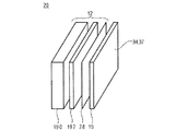
図9は、直接光源12の例として端部照射型導光放射パネルの実施形態を示し、これによると、パネルは、光吸収層82の形態の吸収体と光出射層84との間に挟まれた楔形導光層80を備えて、端部照射型導光放射パネルが全反射により導光し、光吸収層82が楔形層80よりも上流側に配置され、光出射層84が、楔形導光層80よりも下流側に配置される。ここで、n<n<n、nは、楔形導光層80の屈折率、nは光出射層84の屈折率、nは光吸収層82の屈折率である。レイヤ80および84については、これらはガラスまたは透明プラスチックからなる一方、光吸収層82を実現するにはいくつかの可能性がある。楔形層80が、1°未満の楔形の傾斜を特徴付けてもよい。図9に86として示すように、光吸収層82は、実際に、間隙90を隔てて楔形導光層80から分離した、光吸収パネル88であってもよく、間隙は、例えば空気、真空、または低屈折率材で満たされ、その屈折率をnとして示す。他の可能性として、光吸収層82をある種のコーティングで形成することがある。コーティングは、n未満かつn未満となるように充分小さい屈折率nの材料から成る。光吸収層82は、光吸収層82に当たる可視光の少なくとも70%、好ましくは90%、最も好ましくは95%を吸収し得る。 FIG. 9 shows an embodiment of an edge-illuminated light guiding radiation panel as an example of a direct light source 12, according to which the panel is sandwiched between an absorber in the form of a light absorbing layer 82 and a light emitting layer 84. A wedge-shaped light guide layer 80, the end-irradiated light guide radiation panel guides light by total reflection, the light absorption layer 82 is disposed upstream of the wedge-shaped layer 80, and the light emission layer 84 has a wedge shape. The light guide layer 80 is disposed on the downstream side. Here, n 3 <n 2 <n 1 , n 1 is the refractive index of the wedge-shaped light guide layer 80, n 2 is the refractive index of the light emitting layer 84, and n 3 is the refractive index of the light absorbing layer 82. For layers 80 and 84, while they are made of glass or transparent plastic, there are several possibilities for realizing light absorbing layer 82. The wedge-shaped layer 80 may characterize a wedge-shaped slope of less than 1 °. As shown at 86 in FIG. 9, the light absorbing layer 82 may actually be a light absorbing panel 88 separated from the wedge-shaped light guide layer 80 with a gap 90 therebetween, for example, air, vacuum, Alternatively, it is filled with a low refractive index material, and its refractive index is denoted as n 3 . Another possibility is to form the light absorbing layer 82 with some kind of coating. The coating consists of a material with a refractive index n 3 that is small enough to be less than n 1 and less than n 2 . The light absorbing layer 82 can absorb at least 70%, preferably 90%, most preferably 95% of visible light impinging on the light absorbing layer 82.

拡大部92に示すように、光出射層84は、楔形導光層80と光出射層84との境界面96と交差して出射層の上(または外側)面118の法線に対して所定の角度で伝搬する光線98の方向を変えるように、光出射層84と楔形導光層80との境界面96にある複数の微小反射体94を備え、この角度は、上記上面にて全反射の臨界角未満であり、ここで、上記上面は、出射層における楔形層から離れた側の面であり、微小反射体により反射した光は、光出射層外へと方向が変えられて、直接光方向へと伝搬する。   As shown in the enlarged portion 92, the light emitting layer 84 intersects the boundary surface 96 between the wedge-shaped light guide layer 80 and the light emitting layer 84 and is predetermined with respect to the normal line of the upper (or outer) surface 118 of the emitting layer. Is provided with a plurality of micro-reflectors 94 on the boundary surface 96 between the light emitting layer 84 and the wedge-shaped light guide layer 80 so as to change the direction of the light beam 98 propagating at an angle of Here, the upper surface is a surface of the emission layer on the side away from the wedge-shaped layer, and the light reflected by the micro-reflector is directly redirected to the outside of the light emission layer. Propagates in the light direction.

より正確には、図9は、全反射により楔形導光層80内を導光方向106に沿って伝搬する光線を示す。すなわち、この方向は、楔形導光層80が薄くなる勾配方向であり、点97で境界面96と交わり、ここで、境界面96の法線に対する光線の角度は、全反射の臨界角よりもわずかに小さくなっている。このことにより、光の一部が、光線98のように、境界面96と交差し、境界面96に対して小さな角度で導光方向106に沿って伝搬することが可能となる。微小反射体94は、境界面96から楔形導光層80と反対の向きに突出し、上面118で反射した後に光線98の反射が直接光方向32を指すように配列された反射面102を有する。したがって、104として示すように、微小反射体94は、一方向に一様に、すなわち、長手方向には、境界面96内に勾配106の方向に垂直な方向99に沿って形成され、それらの面102は、この導光方向10よりも上流に向き、境界面96の法線方向に近い直接光方向32となるように、例えば、境界面に対して40°から50°に向けられている。特に、微小反射体は、例えば、光出射層84の材料内の溝または空隙として形成されてもよく、この層84の面には、楔形導光層80との境界面96が形成される。しかしながら、他の可能性も存在する。すなわち、図9の端部照射型導光放射パネルは、3層構造(TLS)を備える。中心層80は、楔形であり、屈折率nの透明材料から成る。下層は、屈折率n<nを有し、最終的に層84の上面118からTLS構造に入射する可視光を吸収するようになっている。例えば、周辺光または拡散光発生器10により後方散乱した光を吸収する。上層84は透明であり、屈折率nは、n<n<nを満たし、TLSから光を抽出する空隙微小プリズムなどの微小光学素子を備える。 More precisely, FIG. 9 shows light rays propagating along the light guide direction 106 in the wedge-shaped light guide layer 80 by total reflection. That is, this direction is a gradient direction in which the wedge-shaped light guide layer 80 becomes thin and intersects the boundary surface 96 at a point 97, where the angle of the light ray with respect to the normal of the boundary surface 96 is greater than the critical angle of total reflection. Slightly smaller. As a result, a part of the light crosses the boundary surface 96 like the light ray 98 and can propagate along the light guide direction 106 at a small angle with respect to the boundary surface 96. The micro reflector 94 protrudes from the boundary surface 96 in the direction opposite to the wedge-shaped light guide layer 80, and has a reflecting surface 102 arranged so that the reflection of the light beam 98 directly points in the light direction 32 after being reflected by the upper surface 118. Thus, as shown at 104, the micro-reflectors 94 are formed in one direction uniformly, ie, in the longitudinal direction, along the direction 99 perpendicular to the direction of the gradient 106 in the interface 96, and The surface 102 is directed upstream from the light guide direction 10 and is directed, for example, from 40 ° to 50 ° with respect to the boundary surface so as to be in the direct light direction 32 close to the normal direction of the boundary surface 96. . In particular, the micro-reflector may be formed, for example, as a groove or void in the material of the light emitting layer 84, and a boundary surface 96 with the wedge-shaped light guide layer 80 is formed on the surface of the layer 84. However, there are other possibilities. That is, the edge-illuminated light guide radiation panel of FIG. 9 includes a three-layer structure (TLS). The center layer 80 has a wedge shape and is made of a transparent material having a refractive index n 1 . The lower layer has a refractive index n 3 <n 1 and absorbs visible light that finally enters the TLS structure from the upper surface 118 of the layer 84. For example, ambient light or diffused light from the diffuse light generator 10 is absorbed. The upper layer 84 is transparent, the refractive index n 2 satisfies n 3 <n 2 <n 1 , and includes a micro optical element such as a gap micro prism that extracts light from TLS.

図9の直接光源12は、端面照射体108をさらに備え、この端面照射体は、その端部110からの光を導光方向106に楔形導光層80へと結合させるように構成されている。端面照射体108は、反射集光器などの集光器112と、光源114の形態の第1の光放射デバイスとを備える。集光器112と光源114との組み合わせは、方向106および99により規定された第1の面、ならびに導光方向106を含み面118と垂直な第2の面においてコリメートされる光を発する。第1の面でのコリメートは、第2の面よりも強い。このような集光素子は、図9に示すように、例えば、矩形の複合放物面集光器(CPC)の形状をとり得るものであり、LED光源と結合された矩形入射開口INと、ライトガイド110の入射面に面した矩形出射開口OUTとを備え、4つの放物鏡面を備え、各面は、一次元的に屈曲して発生放物面を有し、いずれも、第1または第2の面内にあり、全ての発生放物面は、入射開口INの面内に焦点を有する。例えば、入射開口INは、第1の面の法線に沿って長尺の薄い矩形状に形成されている。光源114は、LEDなどの第1の光放射デバイス111の1次元アレイで形成され得るもので、同じことが集光器112にも当てはまり、これは、第1の光放射デバイス111と反射器などの集光器113との対の1次元アレイ109が、端面照射体108として利用可能という意味においてである。   The direct light source 12 of FIG. 9 further includes an end surface illuminator 108, which is configured to couple light from its end 110 to the wedge-shaped light guide layer 80 in the light guide direction 106. . The end-face illuminator 108 comprises a concentrator 112, such as a reflective concentrator, and a first light emitting device in the form of a light source 114. The combination of concentrator 112 and light source 114 emits light that is collimated on a first surface defined by directions 106 and 99 and a second surface that includes light guide direction 106 and is perpendicular to surface 118. The collimation on the first surface is stronger than the second surface. Such a condensing element can take the shape of, for example, a rectangular compound parabolic concentrator (CPC), as shown in FIG. 9, and has a rectangular incident aperture IN coupled with an LED light source, A rectangular exit aperture OUT facing the incident surface of the light guide 110, four parabolic mirror surfaces, each surface being bent one-dimensionally and having a generated parabolic surface, Within the second plane, all the generated paraboloids have a focal point in the plane of the entrance aperture IN. For example, the incident opening IN is formed in a long and thin rectangular shape along the normal line of the first surface. The light source 114 may be formed of a one-dimensional array of first light emitting devices 111, such as LEDs, and the same applies to the concentrator 112, which includes the first light emitting device 111 and reflectors, etc. This means that the one-dimensional array 109 paired with the concentrator 113 can be used as the end surface irradiation body 108.

なお、図9に示す実施形態の光学作用原理に関するものにつき、第2の面より強い第1の面でのコリメート作用は、面118に存在する光線が第3の面の同様の発散を特徴付け、第3の面での同様の発散を特徴付け、第3の面は方向32および106を含み、第4の面は方向32および99を含む。実際に、ここに説明する光抽出機構は、光線が境界面96に入射する面における光線の発散を実質的に減少させ得ものであるが、直交面においてではない。層80および84の組み合わせは、はコリメータとして作用し、上記の境界面96へと光線が入射する面内の光線の発散を減少させるので、コリメート光学素子の作用が出射光線の発散を最小化するのに、さらに寄与する。コリメート光学素子112が、白色光などの一次光源114から発せられる光を、楔形導光層80と結合させると、光線100は、光吸収層82に面した層80の下面116と層84に面した境界面96に当たって全反射する。   Note that, with respect to the optical action principle of the embodiment shown in FIG. 9, the collimating action on the first surface, which is stronger than the second surface, characterizes the same divergence of the third surface by the rays present on the surface 118. , Characterized by similar divergence at the third plane, the third plane including directions 32 and 106 and the fourth plane including directions 32 and 99. In fact, the light extraction mechanism described herein can substantially reduce the divergence of the light ray at the surface where the light ray enters the interface 96, but not in the orthogonal plane. The combination of layers 80 and 84 acts as a collimator and reduces the divergence of the rays in the plane where the rays are incident on the interface 96, so that the action of the collimating optics minimizes the divergence of the emitted rays. In addition, it contributes further. When the collimating optical element 112 combines light emitted from the primary light source 114 such as white light with the wedge-shaped light guide layer 80, the light beam 100 faces the lower surface 116 and the layer 84 of the layer 80 facing the light absorbing layer 82. It hits the boundary surface 96 and is totally reflected.

値n/nは、一次光源114と集光器112との組み合わせによって決まる選択された入射光の発散についての結合を保障するのに充分に大きく選択されるべきである。 The value n 1 / n 2 should be selected large enough to ensure coupling for the divergence of the selected incident light, which is determined by the combination of the primary light source 114 and the collector 112.

楔形導光層80の楔構造により、光ビームの発散は、導光層80内の伝搬導光方向106に沿った伝搬が増えるにつれて増加し、境界面96と交差するときに、層80から層84への連続的な漏出をもたらす。すなわち、屈折率値を適切に選択すれば、すなわち、n/n<n/nであれば、中心帯と下部帯との境界で漏出は発生しない。層80と層84との境界96と交差する光は、境界面96にほぼ平行な光出射層84内を伝搬する。すなわち、例えば、境界面96に対して5°未満のわずかなかすめ角をとる。この光は、層80から離れた層84の上面118に当たり、全反射してから、層80と層84との境界面96と再び交差する。一方、光98は、微小反射体94の1つに当たるので、TLS外へと方向32に反射する。端面照射体108の方向を指す微小反射体84の反射面は、これらの反射面102の法線方向が、界面96に対して半分の角度に対応した角度を成し、その方向32は、境界面96とともに、さらに上述の光線98のかすめ角をも加えて、その角度を囲むように、配置されている。換言すれば、角度は、所望の出力角方向32に応じて選択される必要がある。実際に、微小反射体84は、微小プリズムとして形成されてもよく、特に、これらのプリズムは、既に略述して104として図示した空隙プリズムとして形成されてもよい。空隙プリズムは、全反射にて光を反射させることになる。一方、微小反射体は、光出射層84における鏡面コーティングされた刻み目であってもよい。全ての微小反射体94は、互いに平行に配置され、出射方向32が一定になるように同じ頂角を有し得る。 Due to the wedge structure of the wedge-shaped light guide layer 80, the divergence of the light beam increases as propagation along the propagation light guide direction 106 in the light guide layer 80 increases and from layer 80 to layer when intersecting the interface 96. Results in a continuous leak to 84. That is, if the refractive index value is appropriately selected, that is, if n 1 / n 2 <n 1 / n 3 , no leakage occurs at the boundary between the central band and the lower band. Light that intersects the boundary 96 between the layer 80 and the layer 84 propagates in the light emitting layer 84 that is substantially parallel to the boundary surface 96. That is, for example, a slight grazing angle of less than 5 ° with respect to the boundary surface 96 is taken. This light strikes the top surface 118 of the layer 84 away from the layer 80 and is totally reflected before crossing the interface 96 between the layer 80 and layer 84 again. On the other hand, since the light 98 hits one of the minute reflectors 94, the light 98 is reflected in the direction 32 outside the TLS. The reflecting surfaces of the minute reflectors 84 pointing to the direction of the end surface illuminator 108 are such that the normal direction of these reflecting surfaces 102 forms an angle corresponding to a half angle with respect to the interface 96, and the direction 32 is a boundary. Along with the surface 96, the above-described grazing angle of the light ray 98 is added to be arranged so as to surround the angle. In other words, the angle needs to be selected according to the desired output angle direction 32. In practice, the micro-reflector 84 may be formed as a micro-prism, and in particular, these prisms may be formed as gap prisms that have already been outlined and illustrated as 104. The air gap prism reflects light by total reflection. On the other hand, the minute reflector may be a mirror-coated notch in the light emitting layer 84. All the micro reflectors 94 may be arranged in parallel to each other and have the same apex angle so that the emission direction 32 is constant.

微小反射体94の単位面積当たりの寸法および数、すなわち密度は、輝度の均一性を最適化するため、すなわち、既に略述した輝度の均一性の要件に従うため、TSL全体に亘って、すなわち導光方向106に沿って変化する。   The size and number of micro reflectors 94 per unit area, i.e., density, is optimized throughout the TSL, i.e., to optimize brightness uniformity, i.e., to comply with the brightness uniformity requirements already outlined. It changes along the light direction 106.

第3の面における表面118から出射する光線の発散は、一方の第2の面における端面照射体108の入力の発散および他方の楔形勾配が減少するにつれて、減少する。例えば、n/n=1.0076については、約14°の内部モードに対応したライトガイド80となる。0.5°の楔形勾配については、上述の第3の面における方向32にTLSを出射する光の出力の発散は、約2.25°HWHMである。一方、1.001<n/n<1.1で、例えば真となり得る。図9に示す実施形態について、直交面、すなわち第4の面における出力の発散は、第1の面における入力の発散と基本的に同じである。すなわち、既述の2つの直交面における出力の発散は、互いに独立しており、出力角スペクトルまたは輝度角度プロファイルLdirectは、方向32に矩形のピークを示しやすい。矩形スペクトルは、第1および第2の面の入力の発散の比を適切に選択することにより得られる。光源の像の外観における所望の丸み、すなわち、輝点40の丸い外観は、以下に説明するように、図9に示すTLSの下流側に「Leeフィルタ253Hampshire Forst」または「Leeフィルタ750 Durham Frost」などの小角度白色光拡散体(low−angle white−light diffuser)を追加することにより得られる。既知のように、小角度白色光拡散体は、所定の応答関数で照射光の角スペクトルのたたみ込みを実行することにより作用する拡散体であり、ここでは、ある方向(例えば、小角度白色光拡散体の表面の法線)のまわりに対称となり、HWHM発散が10°未満であり、好ましくは5°、より好ましくは2°である。 The divergence of rays emanating from the surface 118 on the third surface decreases as the input divergence of the end-face illuminator 108 on one second surface and the wedge-shaped gradient on the other decrease. For example, for n 1 / n 2 = 1.0076, the light guide 80 corresponds to the internal mode of about 14 °. For a 0.5 ° wedge gradient, the divergence of the output of light exiting the TLS in direction 32 in the third plane described above is about 2.25 ° HWHM. On the other hand, 1.001 <n 1 / n 2 <1.1 may be true, for example. For the embodiment shown in FIG. 9, the output divergence on the orthogonal plane, ie the fourth plane, is essentially the same as the input divergence on the first plane. That is, the output divergence in the two orthogonal planes described above is independent of each other, and the output angle spectrum or the luminance angle profile L direct tends to show a rectangular peak in the direction 32. A rectangular spectrum is obtained by appropriately selecting the ratio of the divergence of the first and second surface inputs. The desired roundness of the appearance of the light source image, that is, the rounded appearance of the bright spot 40, as described below, is “Lee filter 253 Hampshire Forst” or “Lee filter 750 Durham Frost” on the downstream side of TLS shown in FIG. Is obtained by adding a low-angle white-light diffuser. As is known, a small angle white light diffuser is a diffuser that works by performing a convolution of the angular spectrum of the illuminating light with a predetermined response function, where a certain direction (eg, small angle white light diffuser). Symmetric about the diffuser surface normal) and the HWHM divergence is less than 10 °, preferably 5 °, more preferably 2 °.

また、第2の面よりも強い第1の面のコリメート作用を得る目的において、端面照射体108の利用の代替となる解決策は、図6に説明したものと同様のLEDのアレイを用いるが、方向49を含む2つの直交面において2つの異なる発散値をもたらすように構成することによっても得られる。例えば、2つの面における2.25°および20°のHWHM発散は、大きさが0.31・2.8mmの矩形LED発光器46と、焦点距離49が約4mmのレンズドームとを用いることにより得られる。 Further, for the purpose of obtaining a collimating action of the first surface stronger than the second surface, an alternative solution to the use of the end-face illuminator 108 uses an LED array similar to that described in FIG. Can also be obtained by providing two different divergence values in two orthogonal planes including the direction 49. For example, 2.25 ° and 20 ° HWHM divergence in two planes uses a rectangular LED emitter 46 with a size of 0.31 · 2.8 mm 2 and a lens dome with a focal length 49 of about 4 mm. Is obtained.

TLSの光吸収層82が光を吸収することにより、直接光源12がオフの際に外観が黒くなることが保障されるので、反射率輝度プロファイルに関して既に略述した制約、すなわち、出射円錐外の輝度値が低いという制約を満たす。実際に、光吸収層と層80との境界面は、導光層80内で導かれた光についてのみ、鏡面として作用するが、TLS外から到来した光、すなわち外部から直接光源12の光放射面に入射する上述の拡散光などについては、仮想的に透明である。そして、このような光は、例えば、光吸収パネル88により吸収される。   Since the light absorption layer 82 of TLS absorbs light, it is guaranteed that the external appearance becomes black when the light source 12 is directly turned off. Therefore, the constraints already outlined with respect to the reflectance luminance profile, that is, outside the emission cone. Satisfies the constraint that the luminance value is low. Actually, the boundary surface between the light absorption layer and the layer 80 acts as a mirror surface only for the light guided in the light guide layer 80, but the light coming from outside the TLS, that is, the light emission of the light source 12 directly from the outside. The above-described diffused light incident on the surface is virtually transparent. And such light is absorbed by the light absorption panel 88, for example.

図10は、端部照射型導光放射の形態の直接光源12の他の実装例を示す。ここで、端部照射型導光放射パネルは、光吸収層122として形成された吸収体と光出射層124とに挟まれた導光層120を備え、光吸収層122は、導光層120の上流側に配置され、光出射層124は、導光層120の下流側に配置される。層120、122および124の可能な実装例に関して、図9の説明を参照する。ただし、層120から124の屈折率を選択するには、より高い自由度がある。特に、n<nおよびn<nは、nが導光層120の屈折率、nが光出射層124の屈折率、nが光吸収層122の屈折率で充分であり、図9の層82について説明したように、透明な間隙を備える。導光層120は、光が層120および124の境界面134の法線に対して所定の角度で、導光層120内を光出射層124へ向けて導かれるように向きを変えるために、光吸収層122と導光層120との境界面128に、複数の微小反射体126を備え、その角度は、層120内を導かれる光の全反射の臨界角未満である。各微小反射体126は、導光層120から離れた側の光出射層124の外側面132上に形成されたレンズ130の焦点に配置されている。このように、微小反射体126とレンズ130アレイとの組み合わせは、コリメータを構成して、出力光の分散を低下させる。 FIG. 10 shows another implementation of the direct light source 12 in the form of edge-illuminated guided light radiation. Here, the edge irradiation type light guide radiation panel includes a light guide layer 120 sandwiched between an absorber formed as the light absorption layer 122 and the light emission layer 124, and the light absorption layer 122 includes the light guide layer 120. The light emitting layer 124 is disposed on the downstream side of the light guide layer 120. Refer to the description of FIG. 9 for possible implementations of layers 120, 122, and 124. However, there is a higher degree of freedom in selecting the refractive index of layers 120-124. In particular, n 3 <n 1 and n 2 <n 1 are sufficient when n 1 is the refractive index of the light guide layer 120, n 2 is the refractive index of the light emitting layer 124, and n 3 is the refractive index of the light absorbing layer 122. Yes, with a transparent gap as described for layer 82 in FIG. The light guide layer 120 is turned so that the light is guided in the light guide layer 120 toward the light emitting layer 124 at a predetermined angle with respect to the normal line of the boundary surface 134 between the layers 120 and 124. A plurality of minute reflectors 126 are provided on the boundary surface 128 between the light absorption layer 122 and the light guide layer 120, and the angle thereof is less than the critical angle of total reflection of light guided through the layer 120. Each minute reflector 126 is disposed at the focal point of the lens 130 formed on the outer surface 132 of the light emitting layer 124 on the side away from the light guide layer 120. As described above, the combination of the minute reflector 126 and the lens 130 array constitutes a collimator and reduces the dispersion of the output light.

図9の実施形態の他に、図10の端部照射型導光放射パネルの構成は、矩形の導光層120に基づく。すなわち、導光層120は、層122および124とそれぞれ平行な境界面を有する。すなわち、境界面128と光吸収層122、および境界面134と光出射層124である。微小反射体126と、光出射層124の外側面に形成されたコリメートレンズとは、境界面128と外側面132とにそれぞれ沿って、2次元的に分布し、相互に位置決めされ、各微小反射体126およびそれぞれのコリメートレンズ130を通って延びる光軸135は、相互におよび直接光方向32と平行になる。さらに、端面照射体108は、光を導光層120の端部136に結合し、ここで、図10に示すように、この端面照射体108は、第1の光放射デバイス138と、端部136に沿って1次元的に延びる対応する集光器140とのペアの1次元アレイによっても構成され得る。これは図9に示したとおりである。   In addition to the embodiment of FIG. 9, the configuration of the edge-illuminated light guide radiation panel of FIG. 10 is based on a rectangular light guide layer 120. That is, the light guide layer 120 has a boundary surface parallel to each of the layers 122 and 124. That is, the boundary surface 128 and the light absorbing layer 122, and the boundary surface 134 and the light emitting layer 124. The minute reflector 126 and the collimating lens formed on the outer surface of the light emitting layer 124 are two-dimensionally distributed along the boundary surface 128 and the outer surface 132, respectively, and are positioned relative to each other. The optical axes 135 extending through the body 126 and the respective collimating lens 130 are parallel to each other and directly to the light direction 32. Further, the end-face illuminator 108 couples light to the end 136 of the light guide layer 120, where the end-face illuminator 108 is coupled to the first light emitting device 138 and the end as shown in FIG. It may also be constituted by a one-dimensional array of pairs with corresponding concentrators 140 extending one-dimensionally along 136. This is as shown in FIG.

すなわち、各微小反射体126は、コリメートレンズ130のうちの対応する1つに面し、両者は、互いに焦点距離をとって配置される。微小反射体126は、楕円鏡面を有し、この面は、光を反射して、中心伝搬方向142(すなわち、ライトガイドが照明される方向)に沿った導光層120に結合した光を、方向32、すなわち、光軸135に沿って反射するように配置される。特に、微小反射体126の形状は、境界面128から突出した円柱形状であってもよく、既述の鏡角で切られており、この角度は、すなわち、方向32と直交する平面上に突出したときに、円形の断面とするのに必要な角度である。この環境により、円形の出力角スペクトルが保障されて、これにより円形の光源または輝点40の外観が保障される。レンズの焦点距離と、方向32と直交する既述の面内で測定された反射体の大きさ/幅との比は、出力FWHM角スペクトルまたは輝度プロファイルLdirectを規定するので、例えば、所望の分散に応じて、10から100の範囲の値を有し、この幅は、例えば、面134と垂直の方向32について図10にて144と示すものである。例えば、反射体126の直径144が100ミクロンで、レンズの焦点距離146が3mmであり、ここで、焦点距離は、屈折層120および124内で規定されて、面132の下流側の分散HWHMが約1.5°となり、ここで、層120および124の屈折率が、約1.5の値を有するものと想定され、空気中の伝搬が下流側の層124と想定されている。レンズ130の大きさは、微小反射体で反射した光を補足する必要性によって決まる。例えば、焦点距離146と内部ライトガイドモードの半分散の正接の2倍との積の1.5倍とすることができ、これは、レンズ径148が、2×10°の内部分散モードと結合したライトガイドの焦点距離の半分のオーダーであることを意味している。横分布または反射体/レンズ−カプラ対の2次元分布の密度は、いくつかのレンズ径の領域に亘って平均化された輝度の均一性を最大化するために、調整されるべきである。レンズ130は、導光層120との平坦な境界面134を特徴付けるとともに屈折率の低い層124の材料上に形成され得る。この際、レンズ130は、ライトガイド120と干渉せず、第1の放射面28から方向32に出射するように微小反射体126で反射した光についてのみ作用する。 That is, each micro-reflector 126 faces a corresponding one of the collimating lenses 130, and both are arranged with a focal length. The micro-reflector 126 has an elliptical mirror surface, which reflects light and couples light coupled to the light guide layer 120 along the center propagation direction 142 (i.e., the direction in which the light guide is illuminated), It is arranged to reflect along the direction 32, that is, along the optical axis 135. In particular, the shape of the minute reflector 126 may be a cylindrical shape protruding from the boundary surface 128, and is cut by the mirror angle described above, that is, the angle protrudes on a plane orthogonal to the direction 32. The angle is necessary to obtain a circular cross section. This environment ensures a circular output angle spectrum, thereby ensuring the appearance of the circular light source or bright spot 40. The ratio of the focal length of the lens and the size / width of the reflector measured in the plane perpendicular to the direction 32 defines the output FWHM angular spectrum or the luminance profile L direct , for example, as desired. Depending on the variance, it has a value in the range of 10 to 100, and this width is, for example, 144 in FIG. For example, reflector 126 has a diameter 144 of 100 microns and a lens focal length 146 of 3 mm, where the focal length is defined within refractive layers 120 and 124 and the dispersion HWHM downstream of surface 132 is About 1.5 °, where the refractive index of layers 120 and 124 is assumed to have a value of about 1.5, and propagation in air is assumed to be downstream layer 124. The size of the lens 130 is determined by the necessity of supplementing the light reflected by the minute reflector. For example, it can be 1.5 times the product of the focal length 146 and twice the tangent of the semi-dispersion of the internal light guide mode, which is coupled to the internal dispersion mode with a lens diameter 148 of 2 × 10 °. This means that the order is half the focal length of the light guide. The density of the lateral distribution or the two-dimensional distribution of reflector / lens-coupler pairs should be adjusted in order to maximize the uniformity of brightness averaged over several lens diameter regions. The lens 130 may be formed on the material of the layer 124 that characterizes the flat interface 134 with the light guide layer 120 and has a low refractive index. At this time, the lens 130 does not interfere with the light guide 120 and acts only on the light reflected by the minute reflector 126 so as to be emitted from the first radiation surface 28 in the direction 32.

図11は、直接光源12を形成するその他の可能性の概略を示す。その場合、発光体を備えるとともに図11で150として示す第1の光放射デバイスと集光器との組み合わせなどの一次光源は、直接光源の第1の光放射デバイス28を、ミラー系156を介して照射する。図11の場合、ミラー系は、1つのミラー152のみから成る。光源150とミラー系156とは、光源150により発せられた光線154がミラー系156によりコリメートされ、上述の制約のいずれかに従って第1の放射面28から輝度角度プロファイルLdirectで直接光方向32に出射するように、このようにコリメートされて第1の放射面28の後面に当たる。この目的を達成するために、ミラー系156は、例えば、ミラー152のように凹状に屈曲したミラーを備える。換言すれば、一次光源150は、ミラー系156の焦平面に位置し、一次光源150を出射した光のためのコリメータとして作用することになり、一次光源150の開口を、方向32に第1の放射面28を通じて無限遠に結像する。反射率輝度角度プロファイルLについて上記のように特定された制約に従うために、光源150およびミラー系150は、吸収体内に格納される。吸収体は、暗箱158の形状をとり、暗箱の内面に沿って光吸収材で完全に被覆され、第1の放射面28を形成する窓を備える。好ましくは、ミラー系150は、第1の放射面28から暗箱158内部へと光が出射してミラー系156のミラー152に当たることがないように構成され、ミラー系は、光源150から第1の放射面28へと導く光路160に沿って最も下流側に配置され、光がこのミラー系156で反射して第1の放射面28に戻ることがないように構成される。 FIG. 11 outlines other possibilities for forming the direct light source 12. In that case, a primary light source such as a combination of a first light-emitting device and a concentrator, which includes a light emitter and indicated as 150 in FIG. 11, passes the first light-emitting device 28 of a direct light source via a mirror system 156. Irradiate. In the case of FIG. 11, the mirror system includes only one mirror 152. The light source 150 and the mirror system 156 collimate the light beam 154 emitted by the light source 150 by the mirror system 156 and directly in the light direction 32 from the first emitting surface 28 with the luminance angle profile L direct according to any of the above constraints. The light is collimated in this manner so as to be emitted and strikes the rear surface of the first radiation surface 28. In order to achieve this object, the mirror system 156 includes a mirror bent in a concave shape, for example, a mirror 152. In other words, the primary light source 150 is located in the focal plane of the mirror system 156 and acts as a collimator for the light emitted from the primary light source 150, and the opening of the primary light source 150 is moved in the direction 32 in the first direction. An image is formed at infinity through the radiation surface 28. In order to comply with the specified constraint as described above for reflectance luminance angle profile L R, the light source 150 and a mirror system 150 is stored in the absorption body. The absorber is in the shape of a dark box 158 and comprises a window that is completely covered with a light absorber along the inner surface of the dark box and forms a first radiation surface 28. Preferably, the mirror system 150 is configured such that light does not exit from the first radiation surface 28 into the dark box 158 and hit the mirror 152 of the mirror system 156, and the mirror system is It is arranged on the most downstream side along the optical path 160 leading to the radiation surface 28, and is configured so that the light is not reflected by the mirror system 156 and returned to the first radiation surface 28.

なお、図5から図10を参照して提示した直接光源の例は、図11の実施形態よりもコンパクトであり、より容易に実装され、一方の直接光方向32と他方の第1の放射面28の法線方向との角度が、例えば、10°未満またはさらに5°未満となっているという点で有利である。   Note that the direct light source example presented with reference to FIGS. 5 to 10 is more compact and easier to implement than the embodiment of FIG. 11, with one direct light direction 32 and the other first emitting surface. It is advantageous in that the angle with the normal direction of 28 is, for example, less than 10 ° or even less than 5 °.

既に略述した直接光源の実施形態のいくつかは、第1の放射面28の全体に亘って強い空間輝度変調にさらされ得る。例えば、図7および図8の実施形態の場合、各コリメートレンズ64に亘る光の照度は、このような空間変調により特徴づけられる。その空間変調は、例えば、レンズの開口の中央において、各レンズ64の縁よりも数倍強い。しかしながら、これは、図8に示した実施形態では、照度周期変調となり、これは、レイリー様拡散体を拡散光発生器10として用いる場合の問題である。この拡散体は、光放射面で直接光源により発せられた直接光の一部を、波長についての拡散効率のレイリー様の依存性を伴って拡散することにより、拡散光を発する。すなわち、拡散効率は、可視領域では、短波長において長波長よりも強い。このような場合、コリメートレンズ64の既述の照度周期変調は、拡散光発生器10により発せられた拡散光の高いCCT背景の周期輝度変調へと、自動的に変換される。これは、周期輝度変調の極めて高い視覚感度によるものである。このような効果は、自然照明の品質にとって有害である。   Some of the direct light source embodiments already outlined may be subjected to strong spatial intensity modulation throughout the first emitting surface 28. For example, in the embodiment of FIGS. 7 and 8, the illuminance of light across each collimating lens 64 is characterized by such spatial modulation. The spatial modulation is several times stronger than the edge of each lens 64 at the center of the lens opening, for example. However, this is illuminance periodic modulation in the embodiment shown in FIG. 8, which is a problem when using a Rayleigh-like diffuser as the diffused light generator 10. This diffuser emits diffused light by diffusing a part of the direct light emitted by the light source directly on the light emitting surface with the Rayleigh-like dependence of the diffusion efficiency on the wavelength. That is, the diffusion efficiency is stronger at short wavelengths than at long wavelengths in the visible region. In such a case, the above-described illuminance periodic modulation of the collimator lens 64 is automatically converted into periodic luminance modulation of a CCT background with high diffused light emitted by the diffused light generator 10. This is due to the extremely high visual sensitivity of periodic luminance modulation. Such an effect is detrimental to the quality of natural lighting.

この問題に対する第1の解決法は、格天井構造を外側放射面37の下流側に加えることであり、この構造は、例えば、図8の実施形態の場合のコリメートレンズ64と同じピッチを有する、又はコリメートレンズ64のピッチの整数倍又は単位分数であるピッチを有する。   A first solution to this problem is to add a case ceiling structure downstream of the outer radiating surface 37, which structure has, for example, the same pitch as the collimating lens 64 in the embodiment of FIG. The pitch is an integral multiple of the pitch of the collimating lens 64 or a unit fraction.

例えば、格天井構造は、壁面によって分割された隙間容量によって形成されたセルのネットワークを備えており、前記壁面は、僅かな全透過率を有し、外側放射面37の平面及び出力ファセットF_OUTに平行な平面にあり、F_IN及びF_OUTは、同じ形状を有していても有していなくてもよく、F_OUTの重心は方向32に沿ってF_OUT上のF_INの重心の投射に対してずれている可能性があり、F_INが、方向32に沿ってF_INを含む平面上でレンズ64及びレンズ64の開口部の投射内に内接されているという意味では、各セルはレンズ64に面している。   For example, the case ceiling structure comprises a network of cells formed by a gap capacity divided by wall surfaces, the wall surfaces having a slight total transmittance and parallel to the plane of the outer radiation surface 37 and the output facet F_OUT. F_IN and F_OUT may or may not have the same shape, and the center of gravity of F_OUT may be offset from the projection of the center of gravity of F_IN on F_OUT along direction 32 Each cell faces lens 64 in the sense that F_IN is inscribed in the projection of lens 64 and the opening of lens 64 on a plane containing F_IN along direction 32.

例えば、図12を参照すると、さらなる詳細が図8の直接光源12を使用して以下説明されるレイリー拡散パネルとして例示的に具体化された拡散光発生器10の下流側に位置決めされたこのような格天井構造170を示している。図12から分かるように、格天井構造170は、コリメートレンズ64及び対応する第1の光放射デバイス(図12には図示せず)が、図12の場合に拡散光発生器10とコリメートレンズ64の平面の間に延びる放射面28に沿って分散されている周期性174と同一の第1の同期性172を有する。明確にするため、図12に図示した実施形態では、拡散光発生器10は、第1の放射面28の下流側に位置決めされ、したがって、外側放射面27を構成する。普通、格天井構造170の存在は、この場合に限ることを意図するものではないが、第1の放射面28が拡散光発生器10の下流側に位置決めされ、外側放射面37を構成する場合、又は拡散光発生器10の第1の放射面28及び第2の放射面34は適合して、外側放射面37を形成する場合にも当てはまる。   For example, referring to FIG. 12, further details such as this are positioned downstream of the diffuse light generator 10, which is illustratively embodied as a Rayleigh diffuser panel described below using the direct light source 12 of FIG. A simple ceiling structure 170 is shown. As can be seen from FIG. 12, the ceiling structure 170 includes a collimating lens 64 and a corresponding first light-emitting device (not shown in FIG. 12), in the case of FIG. It has a first synchrony 172 that is the same as the periodicity 174 distributed along the emitting surface 28 extending between the planes. For clarity, in the embodiment illustrated in FIG. 12, the diffuse light generator 10 is positioned downstream of the first radiation surface 28 and thus constitutes the outer radiation surface 27. Normally, the presence of the case ceiling structure 170 is not intended to be limited to this case, but when the first radiation surface 28 is positioned downstream of the diffused light generator 10 and constitutes the outer radiation surface 37, Alternatively, the first radiating surface 28 and the second radiating surface 34 of the diffuse light generator 10 may be adapted to form the outer radiating surface 37.

さらに、直接光方向32は、観察者がコリメートレンズ64の輝度変調に起因する輝度周期性を実現することから目をそらせる影響を大きくするために考慮することができる。例えば、格天井構造170の壁面又は側面は、外側放射面37に垂直に配向することができ、直接光方向32は外側放射面37の法線と平行な方向に対して傾斜又は斜めになっている。さらに一般的には、直接光方向32は、格天井構造の外側面の90%より大きく傾斜又は斜めになっている。このように、観察者は、格天井構造170の交互に照明される(低CCT)側面(図12では白く示されている)、及び格天井構造170の陰影の付いた(高CCT)側面(図12では斜線で示されている)を見る。この設定は、強い強度及び色輝度空間変調を作り出し、自然な効果と完全に準拠しており、コリメートレンズ64の不均一な照明によって生じる輝度変調を支配する。しかし、格天井構造170の壁面の外面を傾斜させることによっても同じ効果を得ることができる。例えば、格天井構造の外面は、直接光方向32に沿った投射では、格天井構造170の外面の少なくとも30%は対面しており、格天井構造170の外面の少なくとも30%が防止されるように配向させることができる。後者の環境は、光放射面の法線方向に平行であるように直接光方向32を配置することによってさらに可能になる。   Furthermore, the direct light direction 32 can be taken into account to increase the effect that the observer turns away from realizing the luminance periodicity due to the luminance modulation of the collimating lens 64. For example, the wall surface or side surface of the case ceiling structure 170 can be oriented perpendicular to the outer radiation surface 37, and the direct light direction 32 is inclined or oblique with respect to a direction parallel to the normal of the outer radiation surface 37. . More generally, the direct light direction 32 is inclined or inclined more than 90% of the outer surface of the case ceiling structure. In this way, the observer is alternately illuminated (low CCT) sides of the case ceiling structure 170 (shown in white in FIG. 12) and shaded (high CCT) sides of the case ceiling structure 170 (FIG. 12). (It is shown with diagonal lines.) This setting creates strong intensity and color luminance spatial modulation, is fully compliant with natural effects, and dominates the luminance modulation caused by non-uniform illumination of the collimating lens 64. However, the same effect can be obtained by inclining the outer surface of the wall surface of the case ceiling structure 170. For example, in the projection along the direct light direction 32, the outer surface of the case ceiling structure is oriented so that at least 30% of the outer surface of the case ceiling structure 170 faces and at least 30% of the outer surface of the case ceiling structure 170 is prevented. be able to. The latter environment is further made possible by placing the light direction 32 directly so as to be parallel to the normal direction of the light emitting surface.

図12は、図8による直接光源12に対する実施形態に関する格天井構造を示しているが、格天井構造は次に説明するものを含む直接光源12のあらゆる実施形態と組み合わせることが可能であることを説明すべきである。さらに、周期性174などの周期性はまた、直接光源に対する他の実施形態でも起こる可能性があり、したがって、周期性依存はまた、任意でこのような他の実施形態に当てはめることができる。さらに別の実施形態では、周期性依存は、周期性172は、周期性174の整数倍又は単位分数であるように選択することができる。   FIG. 12 shows the case ceiling structure for the embodiment for the direct light source 12 according to FIG. 8, but it is explained that the case ceiling structure can be combined with any embodiment of the direct light source 12 including those described below. Should. Furthermore, periodicity, such as periodicity 174, can also occur in other embodiments for direct light sources, and thus periodicity dependence can also optionally be applied to such other embodiments. In yet another embodiment, the periodicity dependence can be selected such that the periodicity 172 is an integer multiple or unit fraction of the periodicity 174.

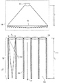
格天井構造をより詳細に明確にするために、図13を参照する。図13は、図12に示した実施形態に言及しており、拡散光発生器の第2の放射面34は、外側放射面37を構成している。拡散光発生器10はまた、以下により詳細に概略を説明するレイリー拡散体であると考えられる。特に、格天井構造170は、コリメートレンズ64の非均一照明による人工空の強度変調の問題を解消する。実際、非均一照明により、レンズ64自体の空間的寸法に沿った非均一出力光強度が決まる。したがって、拡散体パネル10に衝突する非均一光により、拡散青色光内の一連のより明るい及び暗い領域、すなわち「空」内のより明るい及び暗いゾーンが決まる。さらに、拡散体パネルに加えて(図8の例示的な場合では)コリメートレンズのアレイにより、このような強度変調の周期性が決まり、観察者の目によって容易に見分けられる。格天井構造170は、個別のレンズ64に重なる(その第2の放射面34は、この場合、外側放射面37を構成する)拡散体パネル10の個別のゾーンの間に延びる一連のバリアからなり、外側放射面37の外側に延びる、すなわち、そこから突起する。人工太陽からのより低いCCTを有するコリメート直接光成分の方向、すなわち方向32は、外側放射面37と垂直な方向に対して傾斜させることができるので、このような直接光成分は、バリア構造170の側面の半分だけを照明することしかできない。天井を見る場合、観察者は空と各バリア170の一部を見る。より詳細には、観察者は空照明の各高CCTゾーンの間で、「白色」バリアと呼ぶことができる直接照明によって照らされ、したがってより低いCCTを備えたバリア170の一部、又は陰影ゾーンに入る(したがって、「暗い」バリアと呼ぶことができる拡散高CCT成分によって部分的に照明される)バリアの一部を見る。両方の場合とも、バリアの輝度は、空の平均輝度とは非常に異なり、「白色」の場合にははるかに高く、「暗い」場合にははるかに低い。空ゾーンと非常に異なる輝度を有するバリアの間のこのような交代は、人工空の変調をマスキングするのに有用である。というのは、空から「白色」へ、又は空から「暗い」への変調は、上に例示したような意図しない輝度変調から生じる、空自体の内部変調よりもはるかに強いからである。このような空変調はその後、大きく減衰するように見える。格天井構造170はその後、観察者と明らかに均一な空の間の「白色」及び「暗い」グリッドとして見える。   To clarify the case ceiling structure in more detail, reference is made to FIG. FIG. 13 refers to the embodiment shown in FIG. 12 where the second emitting surface 34 of the diffuse light generator constitutes an outer emitting surface 37. The diffuse light generator 10 is also considered to be a Rayleigh diffuser, which will be outlined in more detail below. In particular, the case ceiling structure 170 solves the problem of intensity modulation of the artificial sky due to the non-uniform illumination of the collimating lens 64. Indeed, non-uniform illumination determines the non-uniform output light intensity along the spatial dimensions of the lens 64 itself. Thus, the non-uniform light impinging on the diffuser panel 10 determines a series of brighter and darker areas in the diffuse blue light, ie, brighter and darker zones in the “sky”. Furthermore, in addition to the diffuser panel (in the exemplary case of FIG. 8), an array of collimating lenses determines the periodicity of such intensity modulation and is easily discernable by the observer's eyes. The ceiling structure 170 consists of a series of barriers that extend between individual zones of the diffuser panel 10 that overlap the individual lenses 64 (whose second radiating surface 34 in this case constitutes the outer radiating surface 37); It extends outside the outer radiation surface 37, i.e. protrudes therefrom. Since the direction of the collimated direct light component with a lower CCT from the artificial sun, ie direction 32, can be tilted with respect to the direction perpendicular to the outer radiation surface 37, such direct light component can be reflected by the barrier structure 170. You can only illuminate half of the sides. When looking at the ceiling, the observer looks at the sky and part of each barrier 170. More specifically, the observer is illuminated by direct illumination, which can be referred to as a “white” barrier, between each high CCT zone in the sky illumination, and thus a portion of the barrier 170 with a lower CCT, or shadow zone Look at the part of the barrier that enters (and thus is partly illuminated by the diffuse high CCT component, which can be called the “dark” barrier). In both cases, the brightness of the barrier is very different from the average brightness of the sky, much higher for “white” and much lower for “dark”. Such an alternation between the sky zone and a barrier with very different brightness is useful for masking the modulation of the artificial sky. This is because the modulation from the sky to “white” or from the sky to “dark” is much stronger than the internal modulation of the sky itself resulting from unintentional luminance modulation as illustrated above. Such null modulation then appears to be greatly attenuated. The ceiling structure 170 then appears as a “white” and “dark” grid between the observer and the apparently uniform sky.

図12及び13に関して、本明細書において使用される限り「格天井構造」という用語は、光放射面が水平に配置されて、例えば、部屋の天井に人工照明デバイスを形成する場合にこれらの実施形態を限るものと理解すべきではない。むしろ、この用語は単に、構造170を構造的に説明するものと理解されたい。   With reference to FIGS. 12 and 13, as used herein, the term “case ceiling structure” refers to these embodiments where the light emitting surfaces are arranged horizontally to form, for example, an artificial lighting device on the ceiling of a room. Should not be understood as limiting. Rather, it is to be understood that this term merely describes structure 170 structurally.

最後に、格天井構造170は、拡散光発生器10としてのレイリー拡散体との直接光源12の組合せに関してだけでなく、拡散光発生器10が、その実施形態を以下により詳細に説明する拡散光源からなる他の実施形態に関しても有利であることに留意されたい。また、構造170は、あらゆる他の源12と組み合わせることができ、また、構造170が外側放射面37の下流側に位置決めされている限り、拡散光発生器10が第1の放射面28に対して上流側に位置決めされている場合にもそうである。   Finally, the case ceiling structure 170 is not only related to the combination of the direct light source 12 with the Rayleigh diffuser as the diffuse light generator 10, but the diffuse light generator 10 is from a diffuse light source whose embodiments are described in more detail below. It should be noted that this is also advantageous with respect to other embodiments. Also, the structure 170 can be combined with any other source 12 and the diffuse light generator 10 is relative to the first radiation surface 28 as long as the structure 170 is positioned downstream of the outer radiation surface 37. This is also the case when it is positioned upstream.

図7及び8の実施形態に関して、ちょうど説明した問題、すなわちコリメートレンズの開口部にわたる一定でない照明に関する問題を、その開口部にわたってコリメートレンズ64の均一照明を行なうために、第1の光放射デバイスとコリメートレンズ64の間で第1の光放射デバイス60の下流側に、好ましくは第1の光放射デバイス60のより近くに配置された、自由形状レンズなどの主要レンズの使用によって対処することもできる。他の意味では、自由形状レンズは、コリメートレンズの上で主要光の輝度分布を平坦にするように構成されている。   To solve the problem just described with respect to the embodiment of FIGS. 7 and 8, i.e. the problem of non-constant illumination over the aperture of the collimating lens, to provide uniform illumination of the collimating lens 64 over the aperture, It can also be addressed by the use of a main lens, such as a free-form lens, arranged between the collimating lenses 64 downstream of the first light emitting device 60, preferably closer to the first light emitting device 60. . In another sense, the free-form lens is configured to flatten the luminance distribution of the main light on the collimating lens.

例示的には、図14Aは、光軸68に沿って第1の光放射デバイス60とそのコリメートレンズ64の間に位置決めされた自由形状レンズ180を示している。自然に、このような自由形状レンズ180はまた、各対の第1の光放射デバイス60とコリメートレンズ64に対して、図8の実施形態で使用することができる。   Illustratively, FIG. 14A shows a free-form lens 180 positioned between the first light emitting device 60 and its collimating lens 64 along the optical axis 68. Naturally, such a free-form lens 180 can also be used in the embodiment of FIG. 8 for each pair of first light emitting device 60 and collimating lens 64.

自由形状レンズの問題をよりよく理解するために、図15を参照する。均一照明の要件により、図12及び13に関して上で既に説明したように、均一な空外観により人工照明デバイスの最終知覚が良くなる。しかし、一方の第1の光放射デバイス60ともう一方のコリメートレンズ64の間の光の伝搬により、レンズ64の入力面(開口部)上の輝度分布は一般的に非均一である。さらに、光の損失を最小限にするために、レンズ64の入力面での光分布のさらなる要件は、輝度がレンズ64の開口部の領域の外側で急速に小さくなることである。   To better understand the problem of free-form lenses, refer to FIG. The requirement for uniform illumination improves the final perception of the artificial lighting device due to the uniform sky appearance, as already described above with respect to FIGS. However, due to light propagation between one first light emitting device 60 and the other collimating lens 64, the luminance distribution on the input surface (opening) of the lens 64 is generally non-uniform. Furthermore, to minimize light loss, a further requirement for light distribution at the input surface of lens 64 is that the brightness rapidly decreases outside the area of the aperture of lens 64.

第2の重要な点は、観察者の目に源60が視覚的に現れることである。人工「太陽」の円形画像が得られるので、第1の光放射デバイス60の円形外観が必要である。   The second important point is that the source 60 appears visually in the eyes of the observer. Since a circular image of the artificial “sun” is obtained, a circular appearance of the first light emitting device 60 is required.

自由形状レンズは、前の要件の1つ或いはほとんどを達成することができる。より詳細には、均一な照明の要件は、図15の左手側に示されるように、放射の外側領域に向かって低い伝搬角度で軸方向周りに伝搬する光の方向を変える光学素子を使用することによって対処することができる。
特定の伝搬距離の後、このような強度プロファイルにより、ターゲット上の十分な均一性が達成される。
Free-form lenses can achieve one or most of the previous requirements. More specifically, the requirement for uniform illumination uses an optical element that redirects light propagating around the axis at a low propagation angle towards the outer region of radiation, as shown on the left hand side of FIG. Can be dealt with.
After a certain propagation distance, such an intensity profile achieves sufficient uniformity on the target.

特定の実施形態では、自由形状レンズ180は、自由形状レンズ180がレンズ64を通して観察者の目によって画像化される場合に、丸い光源の視覚的外観を容易にするために、円の形状を特徴とする。   In certain embodiments, the free-form lens 180 features a circular shape to facilitate the visual appearance of a round light source when the free-form lens 180 is imaged by the observer's eye through the lens 64. And

最後に、自由形状レンズと異なる光学成分を前の要件に使用することもできる。例えば、反射複合放物面集光器CPCを使用して、レンズ64上に均一の照明を得ることができる。自由形状レンズの場合と同様に、このようなCPC要素の出力開口部は、CPCの出力開口部がレンズ64を通して観察者の目によって画像化される場合に、丸い光源の視覚的外観を容易にするために、円形であってもよい。完全性のために、図14bは、第1の光放射デバイス60の前、すなわち下流側でこのような反射CPC182を使用することの代替形態を示している。   Finally, optical components different from freeform lenses can be used for the previous requirements. For example, a reflective composite parabolic concentrator CPC can be used to obtain uniform illumination on the lens 64. As with free-form lenses, the output opening of such a CPC element facilitates the visual appearance of a round light source when the output opening of the CPC is imaged by the observer's eye through the lens 64. In order to do so, it may be circular. For completeness, FIG. 14 b shows an alternative to using such a reflective CPC 182 before the first light emitting device 60, ie downstream.

図14A、図14B及び15に示す実施形態の場合、第1の光放射デバイス60の幅74、及び第1の光放射デバイス60とレンズ64の間の距離66は、自由形状レンズ180又はCPC182の存在により、構成の差を説明するために修正される。   For the embodiment shown in FIGS. 14A, 14B and 15, the width 74 of the first light emitting device 60 and the distance 66 between the first light emitting device 60 and the lens 64 are such that the freeform lens 180 or CPC 182 Existence is modified to account for configuration differences.

特に、図14A、図14B及び15の実施形態はまた、図8の実施形態と組み合わせることができる。さらに、図14A、図14B及び15の実施形態はまた、図12及び13の実施形態と組み合わせることができる。   In particular, the embodiment of FIGS. 14A, 14B and 15 can also be combined with the embodiment of FIG. Furthermore, the embodiment of FIGS. 14A, 14B and 15 can also be combined with the embodiment of FIGS.

これまで提供した直接光源12に対する実施形態は、いくつかの場合では、例えば、散乱問題などによる上記輝度角度プロファイル制約を達成する際の小さな問題を示している。以下にさらに概略を説明する実施形態によると、これらの問題は、直接光源12に対する上記実施形態が、コリメート光源190の下流側、及び拡散光発生器10の上流側に位置決めされた微小光学ビームホモジナイザ層192が、ビームホモジナイザ層192と拡散光発生器10の間に位置決めされている、又は拡散光発生器10の下流側に位置決めされた第1の放射面28と共に、事前コリメート光を発生させるコリメート光源190として使用される点において、次に説明する微小光学ビームホモジナイザ層のいずれかで、直接光源12に対して概略を説明した実施形態、すなわち図5から11、14a、b及び15に関して記載したもののいずれかを使用することによって対処される。そのように位置決めされた微小光学ビームホモジナイザ層192は、コリメート光源190から前記ホモジナイザ層192に衝突する迷光の存在によって特徴付けられる第1のコリメートビームを、第1のコリメートビームの発散と同じ又はそれより大きい分散を備え、迷光の影響を受けない第2のコリメートビームに変換する。このような第2のコリメートビームはしたがって、図16に示すように、拡散光発生器10に向かって第1の放射面28を出る。異なる実施形態では、第1の放射面28は、拡散光発生器10の第2の放射面34の下流側に位置決めされる、又はこれと一致し、したがって、ビームホモジナイザ層192から出る第2のコリメートビームは、第1の放射面28に向かって拡散光発生器10の上に衝突する。   The embodiments for the direct light source 12 provided so far show in some cases minor problems in achieving the above luminance angle profile constraints, for example due to scattering problems. According to embodiments described further below, these problems are addressed by the micro-optical beam homogenizer in which the above embodiment for the direct light source 12 is positioned downstream of the collimated light source 190 and upstream of the diffuse light generator 10. A collimator that generates pre-collimated light with a first emitting surface 28 positioned between the beam homogenizer layer 192 and the diffused light generator 10 or positioned downstream of the diffused light generator 10 In terms of its use as light source 190, it has been described with respect to the embodiment outlined for direct light source 12, in any of the micro-optical beam homogenizer layers described below, namely FIGS. 5 to 11, 14a, b and 15. Be addressed by using one of the things. The so-positioned micro-optical beam homogenizer layer 192 is the same as or more than the divergence of the first collimated beam, characterized by the presence of stray light impinging on the homogenizer layer 192 from the collimating light source 190. Convert to a second collimated beam with greater dispersion and unaffected by stray light. Such a second collimated beam thus exits the first radiation surface 28 towards the diffuse light generator 10 as shown in FIG. In a different embodiment, the first emission surface 28 is positioned downstream of or coincides with the second emission surface 34 of the diffuse light generator 10, and thus the second emission surface exiting the beam homogenizer layer 192. The collimated beam impinges on the diffuse light generator 10 toward the first radiation surface 28.

説明したばかりの迷光は、例えば、コリメートレンズ64を具体化するために、フレネルレンズを使用した場合に、いくつかのフレネルレンズの非理想的挙動から生じる可能性がある。このようなフレネルレンズ64の溝先端からの散乱、多数の内部反射などにより、第1の光放射デバイス60によって照らされたフレネルレンズ64は、狭いピーク30からゼロには到達しない輝度プロファイルを有する可能性がある。これに対して、完全に暗い又は均一な背景が必要である、図7及び8の実施形態では、最後にフレネルレンズ64をはっきり視覚可能で明るい物体にする、角度及び位置の両方でも構造化された残りのプロファイルによって特徴付けることができる。このような問題はまた、それぞれ今までのところ説明した、直接光源及びコリメート光源190に対する他の実施形態に関して起こることもある。   The stray light just described can result from the non-ideal behavior of some Fresnel lenses when, for example, a Fresnel lens is used to embody the collimating lens 64. Due to such scattering from the groove tip of the Fresnel lens 64, numerous internal reflections, etc., the Fresnel lens 64 illuminated by the first light emitting device 60 may have a luminance profile that does not reach zero from the narrow peak 30. There is sex. In contrast, in the embodiment of FIGS. 7 and 8, where a completely dark or uniform background is required, it is structured in both angle and position, finally making the Fresnel lens 64 a clearly visible and bright object. It can be characterized by the remaining profile. Such problems may also occur with other embodiments for direct light sources and collimated light sources 190, each of which has been described so far.

このような輝度背景が、その不均一性、及び拡散光発生器10の透明度により、低い、例えば、ピーク輝度値の1%低いとしても、このような輝度背景は視覚可能であり、したがって、自然の空の質を損なう可能性がある。このような問題を解決するため、微小光学ビームホモジナイザ層192を使用することができ、それに対する特定の実施形態を以下にさらに説明する。   Even if such a luminance background is low due to its non-uniformity and the transparency of the diffuse light generator 10, such as 1% lower than the peak luminance value, such a luminance background is visible and therefore natural. May damage the quality of the sky. To solve such problems, a micro-optical beam homogenizer layer 192 can be used, and specific embodiments for it are further described below.

微小光学ビームホモジナイザ層192の第1の実施形態を、図17A〜図17Cを参照して説明する。図17A〜図17Cは、コリメート光源190に対する例として、第1の光放射デバイス60及びフレネルレンズ64などの光放射器及びコリメータの組合せを例示的に示しているが、前のパラグラフで既に説明したように、図17A〜図17Cに例示されたビームホモジナイザ層192は、コリメート光源190及びビームホモジナイザ層192の組合せからなる直接光源12に対する別の実施形態につながるために、上記までに記載した直接光源12に対する実施形態のいずれかと組み合わせることができる。   A first embodiment of the micro-optical beam homogenizer layer 192 will be described with reference to FIGS. 17A to 17C. FIGS. 17A-17C exemplarily illustrate a combination of a light emitter and collimator, such as the first light emitting device 60 and the Fresnel lens 64, as an example for a collimated light source 190, as already described in the previous paragraph. As such, the beam homogenizer layer 192 illustrated in FIGS. 17A-17C is directed to the direct light source described above to lead to another embodiment for the direct light source 12 comprising a combination of the collimated light source 190 and the beam homogenizer layer 192. Can be combined with any of the 12 embodiments.

図17A〜図17Cの微小光学ビームホモジナイザ層192は、2次元アレイの微小レンズ194、及び各微小レンズ194はそれに関連するピンホール196を有するように、2次元アレイの微小レンズ194の下流側に位置決めされ、延びている2次元アレイのピンホール196によって穿孔された吸収層202として成形された吸収体を備えている。図17Aの実施形態は例示的に、直接光方向32が2次元アレイの微小レンズ194を含む平面と垂直である場合のことに言及している。各ピンホール196は、それぞれの微小レンズの焦点長さ198に対応するそれぞれの微小レンズ194に対する長さで、直接光方向32と一致する方向に位置決めされている。以下により詳細に設定した理由により、微小レンズ194は、直径Dを有する円形開口部を有することが好ましい。直径Dは、5mm未満であることが好ましく、3mm未満であることがさらに好ましく、1.5mm未満であることがより好ましい。微小レンズ194は、できるだけ密接に、すなわち可能な最も高い密度で2次元アレイに一緒に固められていることが好ましく、したがって、コリメート光源190として図7及び8の実施形態のいずれかにより、1つのコリメートレンズ64に面する微小レンズ194の数は、図17A〜図17Cに例示的に示したものより高い可能性が極めて高い。例えば、微小レンズ194及びピンホール196がそれぞれ2次元アレイ内に配置されているピッチは、直径Dに等しい、又は少なくとも1.5×D未満であってもよい。 The micro-optic beam homogenizer layer 192 of FIGS. 17A-17C is downstream of the two-dimensional array of microlenses 194 such that each microlens 194 has a pinhole 196 associated therewith. It comprises an absorbent body shaped as an absorbent layer 202 that is positioned and perforated by an extending two-dimensional array of pinholes 196. The embodiment of FIG. 17A exemplarily refers to the case where the direct light direction 32 is perpendicular to the plane containing the two-dimensional array of microlenses 194. Each pinhole 196 has a length corresponding to each microlens 194 corresponding to the focal length 198 of each microlens and is positioned in a direction that directly matches the light direction 32. For the reasons set in more detail below, the micro lenses 194 preferably has a circular opening having a diameter D m. The diameter D m is preferably less than 5 mm, more preferably less than 3 mm, more preferably less than 1.5 mm. The microlenses 194 are preferably consolidated together in a two-dimensional array as closely as possible, i.e. with the highest density possible, and thus, as a collimated light source 190, one of the embodiments of FIGS. The number of microlenses 194 facing the collimating lens 64 is very likely higher than that illustrated in FIGS. 17A-17C. For example, the pitch of the micro lenses 194 and pinhole 196 are disposed respectively in the two-dimensional array is equal to the diameter D m, or at least 1.5 × may be less than D m.

さらに、微小レンズ194の焦点長さf198は、D/f<2・tan(7.5°)、好ましくは<2・tan(5°)、最も好ましくは<2・tan(2.5°)に従うように選択することができる。例示的に円形である可能性があるピンホール196の直径は、コリメート光源190からビームホモジナイザ層192に衝突するコリメート光のHWHM発散θINにしたがって選択される、例えば、dはd≧2ftan(θIN)に従うことがある。 Further, the focal length f m 198 of the microlens 194 is D m / f m <2 · tan (7.5 °), preferably <2 · tan (5 °), most preferably <2 · tan (2 .5 °) can be selected. The diameter of the exemplary pinhole 196 that may be a circle, is selected according to HWHM divergence theta IN of collimated light impinging from the collimating light source 190 to the beam homogenizer layer 192, for example, d m is d m2ftanIN ) may be obeyed.

これらの制約を使用して、輝度プロファイルLdirectへの上記制約は、図17A〜図17Cの実施形態により、第1の放射面28を形成するビームホモジナイザ層192の下流側で達成することができる。異なる実施形態では、以下に説明するように、第1の放射面28は、ビームホモジナイザ層192の下流側に位置決めすることができ、それによって、輝度プロファイルLdirectへの制約は、この表面でのみ達成される。非円形であるピンホール196の形状の場合、dは、ピンホール196と同じ面積を有する円の直径を示すことがある。 Using these constraints, the above constraints on the luminance profile L direct can be achieved downstream of the beam homogenizer layer 192 that forms the first radiation surface 28, according to the embodiment of FIGS. 17A-17C. . In different embodiments, as described below, the first emission surface 28 can be positioned downstream of the beam homogenizer layer 192 so that the constraint on the luminance profile L direct is only at this surface. Achieved. For the shape of the pinholes 196 is non-circular, d m may indicate the diameter of a circle having the same area as the pinhole 196.

また、図17A〜図17Cに示すように、微小光学ビームホモジナイザ層192はさらに、隣り合った対の微小レンズ194及びピンホール196の間のクロストークを小さくするように構成されたチャネル分離構造200として成形された吸収体を備えることができる。特に、チャネル分離構造200は、微小レンズ194の1つがそれぞれの管の上流側に位置決めされ、ピンホール196の1つがその下流側に位置決めされた方向32に沿ってそれぞれ延びる管によって形成することができる。有利には、チャネル分離構造200は、可視領域で光を吸収し、チャネル分離構造200の上に衝突する光に対して、例えば、70%、好ましくは90%、より好ましくは95%より高い吸収度を可視で有する。チャネル分離構造200はまた、図17Bに示すように、微小レンズ194の間の空間204を埋めることができる。   17A to 17C, the micro optical beam homogenizer layer 192 further has a channel separation structure 200 configured to reduce crosstalk between adjacent pairs of micro lenses 194 and pinholes 196. An absorbent body molded as can be provided. In particular, the channel separation structure 200 may be formed by tubes each extending along a direction 32 in which one of the microlenses 194 is positioned upstream of each tube and one of the pinholes 196 is positioned downstream thereof. it can. Advantageously, the channel separation structure 200 absorbs light in the visible region and absorbs, for example, 70%, preferably 90%, more preferably greater than 95% for light impinging on the channel separation structure 200. Has a visible degree. The channel separation structure 200 can also fill the space 204 between the microlenses 194, as shown in FIG. 17B.

ビームホモジナイザ層192の実施形態はしたがって、一連のピンホール196を備えたこれらのレンズ194の焦点面に置かれた吸収マスク202の後に、コリメート光源190から放射される入射コリメート光前面に面するレンズ194の層の使用を利用する。各ピンホール196の中心又はちょうど中心は、方向32の下でレンズアレイのレンズ194の中心又はちょうど中心に対応する、すなわち、レンズ194及びピンホール196アレイは、互いに対して見当合わせされている。この構成により、出力角度プロファイルLdirectは、レンズ194の開口部と同じ形状を特徴とするフラットトップ分布を示す、すなわち、四角形タイプのレンズ開口が使用された場合には四角形フラットトップであり、六角形開口部がレンズ194に対して使用された場合には六角形である。観察者の目内にスポット40の円形画像を有するために、したがって、円形開口部を備えたレンズ194を有する必要がある。開口部間の空間、すなわち空間204は、吸収層で黒くなっているなど、光吸収であるべきである。出力ビームの例えば、θHWHMによって測定したような発散は、θHWHM≒arctan(D/(2f))などの、レンズ194の焦点長さf及び全直径Dに関連している。 The embodiment of the beam homogenizer layer 192 is therefore a lens facing the front of the incident collimated light emitted from the collimating light source 190 after the absorption mask 202 placed in the focal plane of these lenses 194 with a series of pinholes 196. Utilizes the use of 194 layers. The center or just center of each pinhole 196 corresponds to the center or just center of the lens 194 of the lens array under direction 32, ie, the lens 194 and the pinhole 196 array are registered with respect to each other. With this configuration, the output angle profile L direct exhibits a flat top distribution characterized by the same shape as the aperture of the lens 194, that is, a square flat top when a square type lens aperture is used, When a square opening is used for lens 194, it is hexagonal. In order to have a circular image of the spot 40 in the observer's eye, it is therefore necessary to have a lens 194 with a circular opening. The space between the openings, i.e. the space 204, should be light absorbing, such as blackened by the absorbing layer. The divergence of the output beam, for example as measured by θ HWHM , is related to the focal length f m and total diameter D m of the lens 194, such as θ HWHM ≈arctan (D m / (2f m )).

コリメート光源190からレンズ194のアレイに衝突するビームの発散は、フラットトップ分布のブレを案内し、したがって、円形画像の鮮明な位数を円滑にすることによって、出力発散θHWHMに影響を与える。ピンホール196の直径はまた、出力角度分布Ldirectの鮮明さに影響を与える。より小さいピンホール196は、より鮮明な画像を暗示するが、レンズ194のアレイの前の共に比較的大きい発散を備えたより小さいピンホール196はまた、吸収マスク202でのより高い損失を意味する。 The divergence of the beam impinging on the array of lenses 194 from the collimating light source 190 affects the output divergence θ HWHM by guiding the blur of the flat top distribution and thus smoothing the sharp order of the circular image. The diameter of the pinhole 196 also affects the sharpness of the output angle distribution L direct . A smaller pinhole 196 implies a sharper image, but a smaller pinhole 196 with a relatively large divergence together in front of the array of lenses 194 also means a higher loss at the absorption mask 202.

図17A〜図17Cのビームホモジナイザ層192は、最後の層、すなわちビームホモジナイザの下流端部に配置されたものが、観察者の目に対してレンズ194のアレイの存在をマスキングする、2次元アレイのピンホールによって穿孔された黒い(吸収)層である。したがって、図17A〜図17Cの実施形態は、反射輝度を最小限に抑える、すなわち、デバイスがオフの場合に直接光源12の黒い外観を保証する目的に関して最適の性能を保証する。   The beam homogenizer layer 192 of FIGS. 17A-17C is a two-dimensional array in which the last layer, ie, located at the downstream end of the beam homogenizer, masks the presence of an array of lenses 194 to the viewer's eyes. A black (absorbing) layer perforated by a pinhole. Thus, the embodiment of FIGS. 17A-17C ensures optimal performance with respect to the objective of minimizing reflected brightness, ie, ensuring the black appearance of the light source 12 directly when the device is off.

しかし、伝達及び吸収ゾーンの変更によるピンホール層202に関連する画像のピクセル化を避けるためには、低角度白色光拡散体230は、ピンホール196の画像をぼかし、第1の放射面28とその後一致する低角度白色光拡散体230平面で均一な輝度を保証するように、以下に記載するように、ピンホール層202の下流側に位置決めすることができる。輝度プロファイルの狭いピーク30内の余分なブレを防ぐために、白色光拡散体230は、HWHM応答関数≦10°、好ましくは≦5°、より好ましくは≦2°をとる。輝度均一を保証するために、白色光拡散体230は、ピンホール層202の平面から十分離れて、例えば、fから1から3倍の距離に置かれる。しかし、白色光拡散体230の使用は常に必要ではない、例えば、観察者は大きな距離(例えば、3〜5mの距離)からの照明デバイスを観察することになっている場合に必要ないことがあり、レンズ194の直径Dが観察の予測距離に対して十分小さく、例えば、1mm未満、好ましくは0.5mm未満をとる場合に必要ない。 However, to avoid pixelation of the image associated with the pinhole layer 202 due to transmission and absorption zone changes, the low angle white light diffuser 230 blurs the image of the pinhole 196 and It can then be positioned downstream of the pinhole layer 202 as described below to ensure uniform brightness in the plane of the matching low angle white light diffuser 230. In order to prevent excessive blurring within the narrow peak 30 of the luminance profile, the white light diffuser 230 takes a HWHM response function ≦ 10 °, preferably ≦ 5 °, more preferably ≦ 2 °. To ensure uniform brightness, white light diffuser 230 is sufficiently away from the plane of the pinhole layer 202, for example, it is placed from 1 to f m to 3 times the distance. However, the use of white light diffuser 230 is not always necessary, for example, if the observer is supposed to observe a lighting device from a large distance (eg, a distance of 3-5 m), it may not be necessary. This is not necessary when the diameter D m of the lens 194 is sufficiently small relative to the predicted distance of observation, for example, less than 1 mm, preferably less than 0.5 mm.

レンズ194のアレイ、及びピンホール196のアレイを見当合わせする問題が、レンズ194のアレイ自体によりピンホール196のアレイを製造することによって直接解決されても意味がない。例えば、製造プロセスの始めでは、連続層である、すなわちいかなるホール/ピンホール196もない吸収層202上のレンズ194によって焦点が合わせられた高強度層は、層202内にピンホール196をエッチングする。このようなレーザビームの出力及び発散を制御することによって、ピンホール寸法、すなわち、ピンホール直径dは、適当に設定される。 There is no point in solving the problem of registering the array of lenses 194 and the array of pinholes 196 directly by manufacturing the array of pinholes 196 with the array of lenses 194 itself. For example, at the beginning of the manufacturing process, a high-strength layer that is focused by the lens 194 on the absorbing layer 202 that is a continuous layer, ie, without any holes / pinholes 196, etches the pinholes 196 in the layer 202. . By controlling the output and divergence of such a laser beam, the pinhole size, i.e., a pinhole diameter d m is set appropriately.

例として、レンズ194に対する1.5mmの開口部、及び約1.7cmの焦点長さは、2.5°の半分の角度出力発散につながり、上に記載したように、直接光の所望の発散に近づく。   As an example, a 1.5 mm aperture for lens 194 and a focal length of about 1.7 cm leads to an angular output divergence of half the 2.5 °, and as described above, the desired divergence of direct light. Get closer to.

記載したチャネル分離構造200の使用は、任意選択であるが、隣り合った対のレンズ194及びピンホール196の間のクロストーク効果を防ぐためのものである。これらのクロストーク効果は、中心高強度のものの周りの太陽画像の一連のゴースト複製内に現れる可能性がある。これらは、図17Aで光線206によって示されるように、十分に大きい伝搬角度、例えば(D/f)−(d/(2f))ラジアンより大きい、ビームホモジナイザ層192に衝突する光ビーム内の強い迷光の存在で起こることがある。この場合、大きな角度で伝搬するこのように強い迷光206は、隣接するレンズ194に関連するピンホール106内で1つのレンズ194によって焦点を合わせることができる。 The use of the described channel separation structure 200 is optional, but to prevent crosstalk effects between adjacent pairs of lenses 194 and pinholes 196. These crosstalk effects can appear in a series of ghost replicas of the sun image around the central high intensity one. These are light impinging on the beam homogenizer layer 192 that is greater than a sufficiently large propagation angle, eg, (D m / f m ) − (d m / (2f m )) radians, as shown by light ray 206 in FIG. 17A. May be caused by the presence of strong stray light in the beam. In this case, such intense stray light 206 propagating at a large angle can be focused by one lens 194 within the pinhole 106 associated with the adjacent lens 194.

上で説明し、図17A〜図17Cに示したように、チャネル分離構造は、吸収材料の管のアレイ、すなわちレンズ194及びピンホール196の対毎に1つの管で形成することができ、これらの管はレンズ194のアレイとピンホール196のアレイの間に位置決めされた要素の第3のアレイを構成している。大きな角度でレンズ194のアレイに衝突し、チャネル分離構造200なしで、隣接するピンホール、すなわち隣接するレンズ194に属するピンホール上で焦点が合わせられる光は、その後、チャネル分離構造200によって吸収され、したがってクロストークがなくなる。出力ピンホール層200はまた、後者の場合になくすことができる。というのは、これらは、出力輝度分布に角度ブレを加える代償を払って、チャネル分離構造200自体の管の開口部に置き換えられる。   As described above and shown in FIGS. 17A-17C, the channel isolation structure can be formed of an array of tubes of absorbent material, ie, one tube per lens 194 and pinhole 196 pair, This tube constitutes a third array of elements positioned between the array of lenses 194 and the array of pinholes 196. Light that strikes the array of lenses 194 at a large angle and is focused on an adjacent pinhole, ie, a pinhole belonging to the adjacent lens 194, without the channel separation structure 200 is then absorbed by the channel separation structure 200. Thus, there is no crosstalk. The output pinhole layer 200 can also be eliminated in the latter case. This is because they are replaced by the opening of the tube of the channel separation structure 200 itself at the cost of adding angular blur to the output luminance distribution.

したがって、図18に示すように、微小光学ビームホモジナイザ層192に対する別の実施形態は、2次元アレイの微小レンズ194と、2次元アレイの微小レンズ194の下流側に延びる2次元アレイの微小管200のチャネル分離構造として成形された吸収体とを備えており、それによって、各微小レンズ194は、図17A〜図17Cの実施形態の場合と同様に、それぞれの微小レンズ194から直接光方向32に延びるこれに関連した微小管を有する。微小レンズ194の直径D、及び微小レンズ194の焦点長さfに関連して、図17A〜図17Cの実施形態の説明を参照する。図18で211と印がつけられた微小管200の長さlに関して、このような長さlは必ずしもfと等しくなく、0.5f<l<1.2fの範囲で変化してもよい。 Accordingly, as shown in FIG. 18, another embodiment for the micro-optical beam homogenizer layer 192 is a two-dimensional array of microlenses 194 and a two-dimensional array of microtubules 200 extending downstream of the two-dimensional array of microlenses 194. In which the microlenses 194 are arranged in the light direction 32 directly from the respective microlenses 194 as in the embodiment of FIGS. 17A to 17C. Has an associated microtubule that extends. In connection with the diameter D m of the microlens 194 and the focal length f m of the microlens 194, reference is made to the description of the embodiment of FIGS. With respect to the length l of FIG. 18 at 211 and microtubules 200 marked, such length l is not necessarily equal to f m, and varies from 0.5f m <l <1.2f m Also good.

図19は、微小光学ビームホモジナイザ層192に対する別の実施形態を示している。図17A〜図17C及び図18それぞれの場合と同様に、微小光学ビームホモジナイザ層192は図では、直接光源12に対する別の実施形態を形成するように、コリメート光源190と組み合わせられているが、放射器及びコリメータを備えたコリメート光源190は例示的には、図7の例と同様に、フレネルレンズ64と第1の光放射デバイス60の組合せを備えているように示されており、図5から11、14及び15の前に記載した例のいずれも、コリメート光源190を実施するために使用することができる。   FIG. 19 shows another embodiment for the micro-optical beam homogenizer layer 192. As in each of FIGS. 17A-17C and FIG. 18, the micro-optic beam homogenizer layer 192 is combined with a collimated light source 190 to form another embodiment for the direct light source 12 in the figure. A collimating light source 190 with a vessel and a collimator is illustratively shown as comprising a combination of Fresnel lens 64 and first light emitting device 60, similar to the example of FIG. Any of the examples described before 11, 14, and 15 can be used to implement the collimated light source 190.

図19の微小光学ビームホモジナイザ層192は、焦点長さfm1の第1の2次元アレイの微小レンズ210、焦点長さfm2の第2の2次元アレイの微小レンズ212、及び六角形などにつめられたようなアレイ状に横方向に分配され、互いに平行であり、直接光方向32と平行な望遠鏡軸を有する望遠鏡216のアレイを形成するように、第1及び第2のアレイの微小レンズ210、212の間に配置されたピンホール214のアレイによって穿孔された吸収層220として成形された吸収体を備えている。各望遠鏡216では、それぞれのピンホール214、第1の2次元アレイのそれぞれの微小レンズ210、及び第2の2次元アレイのそれぞれの微小レンズ212が、fm1である第1の2次元アレイのそれぞれのピンホール214とそれぞれの微小レンズ210の間の距離、及びfm2である第2の2次元アレイのそれぞれのピンホール214とそれぞれの微小レンズ212の間の距離で、望遠鏡軸に沿って配置されている。fm2<γ・fm1において、γ<1、好ましくはγ≦0.9、最も好ましくはγ≦0.85である。望遠鏡216のアレイの下流側に面した外面218は、反射防止コーティングを備えることができる。 The micro-optical beam homogenizer layer 192 in FIG. 19 is formed in a first two-dimensional array of microlenses 210 having a focal length f m1 , a second two-dimensional array of microlenses 212 having a focal length f m2 , and a hexagon. The microlenses of the first and second arrays so as to form an array of telescopes 216 that are distributed laterally in an array such as a nail and are parallel to each other and have a direct telescope axis parallel to the light direction 32 It comprises an absorbent body shaped as an absorbent layer 220 perforated by an array of pinholes 214 disposed between 210 and 212. In each telescope 216, the respective pinhole 214, the respective microlenses 210 of the first two-dimensional array, and the respective microlenses 212 of the second two-dimensional array are of the first two-dimensional array of f m1 . Along the telescope axis at a distance between each pinhole 214 and each microlens 210, and a distance between each pinhole 214 and each microlens 212 of the second two-dimensional array, which is f m2. Has been placed. In f m2 <γ · f m1 , γ <1, preferably γ ≦ 0.9, and most preferably γ ≦ 0.85. The outer surface 218 facing the downstream side of the array of telescopes 216 can be provided with an anti-reflective coating.

図19の実施形態では、ビームホモジナイザ層192はしたがって、2つのアレイのレンズ210、212、及びピンホール214の中心アレイから構成されている。両方のレンズ210及び212の焦点平面に配置されたピンホール214は、薄い層の光吸収材料から切り出すことができる。したがって、図19の構成は、図17A〜図17C及び図18に示した微小光学ビームホモジナイザシステムと同様であるが、レンズ212の追加アレイを備えている。各レンズ210の開口部は、下流側アレイのレンズ212の開口部に、2つのレンズ210と212の間の軸217上で中心合わせされたピンホール214に対応する。ビームホモジナイザ層192はしたがって、光学望遠フィルタのアレイを形成する。中にピンホール214が形成された吸収層220は、全ての空間的成分、すなわち、焦点平面内ではピンホール214の外側になる伝搬角度をなくす。このビームホモジナイザ層の出力発散は、全幅において測定され、ビームホモジナイザ192に衝突する光の入力半幅拡散のfm1/fm2倍と、Δθ≒arctan(d/2・fm2)の間の最低値であり、dはピンホール214のピンホール直径である。観察者の目に形成される画像は、下流側アレイの1つの単レンズ212の焦点平面の画像である。したがって、円形画像がピンホール214の円形形状によって与えられる。さらに、コリメートレンズ64が存在する場合、レンズ210と同じ存在により、中心ピンホール214の上に主要光源60が画像化される。したがって、図7及び8に示すむき出しになったコリメートレンズの場合と同様に、観察者の目の中で、図19の直接光源12は、ピンホール開口部214によってクリッピングすることができる主要光源60を画像化する。コリメート光源190からレンズ210のアレイに衝突する光は、例えば、コリメートレンズ64の出口などで初期発散を示すので、焦点長さfm1及びfm2は同じであるべきではない。第1のアレイ210のレンズに衝突する光の入力発散が与えられる、1:1顕微鏡216は実際、このようなアレイ212に属する対応するレンズの全開口部より大きい第2のアレイ212の平面上でのスポットの生成につながる。このような場合はしたがって、このような対応する出力レンズの周りの隣接するレンズの望ましくない照明につながる。所与の入力発散に対する幾何学的検討から、下流側アレイのより短い焦点長さfm2により、このような効果なしでアレイ212の単レンズの出力開口部の全照明が決まる。 In the embodiment of FIG. 19, the beam homogenizer layer 192 is thus composed of two arrays of lenses 210, 212 and a central array of pinholes 214. A pinhole 214 located in the focal plane of both lenses 210 and 212 can be cut from a thin layer of light absorbing material. Accordingly, the configuration of FIG. 19 is similar to the micro-optical beam homogenizer system shown in FIGS. 17A-17C and 18, but with an additional array of lenses 212. The opening of each lens 210 corresponds to a pinhole 214 centered on the axis 217 between the two lenses 210 and 212 to the opening of the lens 212 in the downstream array. The beam homogenizer layer 192 thus forms an array of optical telephoto filters. The absorption layer 220 with the pinhole 214 formed therein eliminates all spatial components, that is, the propagation angle that is outside the pinhole 214 in the focal plane. The output divergence of this beam homogenizer layer is measured at full width and is the lowest between f m1 / f m2 times the input half-width diffusion of light impinging on the beam homogenizer 192 and Δθ≈arctan (d m / 2 · f m2 ). a value, the d m a pinhole diameter of the pinhole 214. The image formed in the eyes of the observer is an image of the focal plane of one single lens 212 in the downstream array. Thus, a circular image is provided by the circular shape of the pinhole 214. Further, when the collimating lens 64 is present, the main light source 60 is imaged on the central pinhole 214 due to the same presence as the lens 210. Thus, as in the case of the bare collimating lens shown in FIGS. 7 and 8, the direct light source 12 of FIG. 19 is the main light source 60 that can be clipped by the pinhole opening 214 in the eyes of the observer. Image. The light impinging on the array of lenses 210 from the collimating light source 190 exhibits an initial divergence, such as at the exit of the collimating lens 64, so the focal lengths f m1 and f m2 should not be the same. Given the input divergence of the light impinging on the lenses of the first array 210, the 1: 1 microscope 216 is actually in the plane of the second array 212 that is larger than the full aperture of the corresponding lens belonging to such an array 212. Leads to the generation of spots. Such a case therefore leads to undesirable illumination of adjacent lenses around such a corresponding output lens. From geometric considerations for a given input divergence, the shorter focal length f m2 of the downstream array determines the total illumination of the single lens output aperture of the array 212 without such effects.

吸収層220での光損失を少なくするために、ピンホール直径dは、コリメート光源190から入射するビームの発散にしたがって選択することができることが望ましい。主要源60が、例えば、円形形状を呈していない場合、ピンホール214に関して損失がある可能性がある。図17及び18のビームホモジナイザ層192の場合に対して、図19の例は、レンズ210の開口部は円形である必要はなく、その入力面の部分の黒色化は必要ない。すなわち、レンズ210の開口部は互いに当接して、コリメートレンズ64の横寸法、又は図8の場合にはこのようなレンズ64のアレイなどのコリメート光源190から入射する光前部の横延長部と連続して位相が重なる、及び重複することができる。 In order to reduce the light loss in the absorption layer 220, the pinhole diameter d m, it is desirable to be able to choose in accordance with the divergence of the beam incident from the collimating light source 190. If the main source 60 does not exhibit a circular shape, for example, there may be a loss with respect to the pinhole 214. In the case of the beam homogenizer layer 192 of FIGS. 17 and 18, in the example of FIG. 19, the opening of the lens 210 does not need to be circular, and the blackening of the input surface portion is not necessary. That is, the apertures of the lens 210 abut each other and the lateral dimension of the collimating lens 64, or in the case of FIG. 8, a lateral extension of the front part of the light incident from a collimating light source 190, such as an array of such lenses 64. Phases can overlap and overlap in succession.

中心吸収層220内のピンホール214は、図17A〜図17Cに関して上に記載した製造プロセスの説明と同様に、レンズ210の第1のアレイによって焦点が合わせられた高強度レーザビームの使用によって書き込むことができる。   The pinhole 214 in the central absorber layer 220 is written by use of a high intensity laser beam focused by the first array of lenses 210, similar to the description of the manufacturing process described above with respect to FIGS. 17A-17C. be able to.

すなわち、レーザ印刷を使用して、微小レンズはピンホールを製造しなければならない正確な位置でレーザビームに焦点を合わせるように、上流側微小レンズ層を通して適切にコリメートされたレーザビームによって上記成分を照らし、ピンホールの所望の直径が得られるように露光時間及びビーム散乱を調節することによって得られるピンホールのレーザ微小製造の後に、ピンホールを位置決めしなければならない表面上に連続遮断層が蒸着されているという事実とは別に、開示するホモジナイザと同一の成分の第1の実現に依存する上記微小光学ビームホモジナイザ層のピンホールを形成することができる。   That is, using laser printing, the microlens is focused by the laser beam appropriately collimated through the upstream microlens layer so that the microlens is focused on the laser beam at the exact location where the pinhole must be manufactured. After laser microfabrication of the pinhole obtained by illuminating and adjusting the exposure time and beam scattering to obtain the desired diameter of the pinhole, a continuous barrier layer is deposited on the surface where the pinhole must be positioned Apart from that, pinholes in the micro-optical beam homogenizer layer can be formed that depend on a first realization of the same components as the disclosed homogenizer.

図17A〜図17C及び図18のビームホモジナイザ層の出力層のピクセル化に関する検討は、図19の場合にも当てはまる。したがって、レンズ212の開口部は、5mm未満、好ましくは3mm未満、最も好ましくは1.5mm未満であってもよい。しかし、最終散乱は、一方ではレンズ210及び212のレンズ開口部間の比に、もう一方では焦点長さfm1及びfm2に関連していないので、レンズ210及び212の焦点長さfm1及びfm2はそれぞれ、ほぼレンズ210及び212の開口部である、すなわち、図17及び18の実施形態の場合よりはるかに短い。 The discussion on pixelization of the output layer of the beam homogenizer layer of FIGS. 17A to 17C and FIG. 18 also applies to the case of FIG. Thus, the opening of lens 212 may be less than 5 mm, preferably less than 3 mm, and most preferably less than 1.5 mm. However, the final scattering, whereas the ratio between the lens opening of the lens 210 and 212, since on the other hand does not relate to the focal length f m1 and f m @ 2, the focal length of the lens 210 and 212 f m1 and f m2 is approximately the aperture of lenses 210 and 212, respectively, ie, much shorter than in the embodiment of FIGS.

十分に大きい、例えば、D及びdはそれぞれレンズ210及びピンホール214の直径である、(D/fm1)−(d/(2 fm1))ラジアンより大きい伝搬角度で、ビームホモジナイザ層192に衝突する光ビーム内の強い迷光が存在する状態で、クロストークは、図17の実施形態で説明したように、図19の実施形態でも起こる。隣接するレンズ210に属するピンホール内に1つのレンズ210によって焦点が合わせられた光222から生じる前記クロストークは、レンズ210のレンズ開口部、焦点長さfm2、及びピンホール直径dに依存する、大きな伝搬角度で所望の出力スポットの薄れた複製につながる可能性がある。所望の出力スポットの前記薄れた複製が見える可能性がある角度は、図19の実施形態では、図17よりはるかに大きく、例えば、約45°である。その理由は、ピッチと焦点長さの間の比のはるかに大きな値、及びレンズ194に関してレンズ210によって隣接するピンホールが見られるはるかに大きな角度である。図19の実施形態の場合では、例えば、1次クロストークの場合では、これを通して前記クロストークが予め成形される二次顕微鏡(すなわち、入力レンズ210、及び入力レンズ210の前に位置決めされたレンズ210に二番目に隣接した出力レンズによって形成された顕微鏡)は、コリメート光を伝達することが可能ではない。実際、方向32に対して大きく傾斜した前記二次顕微鏡の軸であり(D≒fm1の典型的な場合に、約45°である)、前記二次顕微鏡のピンホール214と出力レンズ212の間の距離はfm2よりはるかに大きく(例えば、√2倍大きい)、二次顕微鏡軸の方向にレンズ212の実際の焦点長さは、大きな動作角度によって生じる非点収差により、公称値fm2より実質的に短い。この状況では、平行方向に沿ってレンズ212から次第に出る光線は、ピンホール214によって遮断される。というのは、前記ピンホールは二次顕微鏡軸の方向にレンズ212の実焦点から離れているからである。二次顕微鏡が平行光線を伝達することができないという事実は、輝度プロファイル中の二次的な狭いピーク、すなわち、ピーク30の幅に相当するピークにつながるクロストーク形を防ぐ。すなわち、クロストークにより形成することができる二次スポットは、ビームホモジナイザ層192に衝突する非コリメート光の場合でさえも、はるかに大きくぶれ、したがって、はるかに見えにくい。より高次のクロストークは、方向32に対するより大きな顕微鏡軸角度により、さらに大きなブレ効果につながる。したがって、図17の実施形態が、チャネル分離構造200なしで作用する限り、図19の実施形態は、図17の実施形態に対してはるかに弱いクロストークを発生する利点があり、動作される価格はレンズ210に対するレンズ212のアレイを見当合わせする必要性に関連している。 Sufficiently large, for example, D m and d m is the diameter of each lens 210 and pinhole 214, (D m / f m1 ) - in (d m / (2 f m1 )) radians greater than the propagation angle, the beam Crosstalk also occurs in the embodiment of FIG. 19, as described in the embodiment of FIG. 17, in the presence of strong stray light in the light beam that impinges on the homogenizer layer 192. The crosstalk caused from the adjacent light 222 focused by a single lens 210 in the pin holes belonging to the lens 210 is aligned to the lens aperture of the lens 210, the focal length f m @ 2, and the pinhole diameter d m depends Can lead to faint replication of the desired output spot at large propagation angles. The angle at which the faint replica of the desired output spot may be visible is much larger in FIG. 19 than in FIG. 17, for example about 45 °. The reason is the much larger value of the ratio between pitch and focal length, and the much larger angle at which the adjacent pinhole is seen by lens 210 with respect to lens 194. In the case of the embodiment of FIG. 19, for example, in the case of primary crosstalk, a secondary microscope through which the crosstalk is preformed (ie, the input lens 210 and the lens positioned in front of the input lens 210). The microscope formed by the output lens second adjacent to 210) is not capable of transmitting collimated light. In fact, it is the axis of the secondary microscope that is largely inclined with respect to direction 32 (about 45 ° in the typical case of D m ≈f m1 ), and the pinhole 214 and output lens 212 of the secondary microscope. Is much larger than f m2 (eg, √2 times larger), and the actual focal length of the lens 212 in the direction of the secondary microscope axis is the nominal value f due to the astigmatism caused by the large operating angle. It is substantially shorter than m2 . In this situation, light rays that gradually exit the lens 212 along the parallel direction are blocked by the pinhole 214. This is because the pinhole is away from the actual focus of the lens 212 in the direction of the secondary microscope axis. The fact that the secondary microscope cannot transmit parallel rays prevents a crosstalk shape that leads to a secondary narrow peak in the luminance profile, ie a peak corresponding to the width of the peak 30. That is, the secondary spots that can be formed by crosstalk are much more blurred, and therefore much less visible, even in the case of non-collimated light impinging on the beam homogenizer layer 192. Higher order crosstalk leads to a greater blur effect due to a larger microscope axis angle relative to direction 32. Thus, as long as the embodiment of FIG. 17 operates without the channel isolation structure 200, the embodiment of FIG. 19 has the advantage of generating much weaker crosstalk than the embodiment of FIG. Is related to the need to register an array of lenses 212 to lenses 210.

別の実施形態では、顕微鏡216毎に1つの吸収管がある、吸収管のアレイ、すなわち吸収チャネル分離構造224は、レンズ210のアレイの下流側に位置決めされている。チャネル分離構造200の場合、図17A〜図17C及び図18の実施形態の場合に関して、前記吸収チャネル分離構造224は、停止クロストーク222の関数を有し、これはしかし、ちょうど説明した前の場合よりもここでははるかに影響が少ない。この吸収チャネル分離構造224のバリアは、レンズ210と直接接触しているグリッドを形成することができる。レンズ直径と焦点長さの間の比は、図17A及び図18の実施形態ではレンズ194の場合より、図19の実施形態のレンズ210の場合でははるかに大きい、例えば、3〜30倍大きい可能性があるので、吸収チャネル分離構造224の個別の管の吸収チャネル分離構造224、すなわち、レンズ210の開口部228によって分割される管長さ226は、図17及び18の場合よりはるかに低い、例えば、0.5〜3の範囲である可能性があり、したがって、はるかに少ない要求の技術的労力につながる。   In another embodiment, an array of absorption tubes, or absorption channel separation structure 224, with one absorption tube per microscope 216, is positioned downstream of the array of lenses 210. In the case of the channel separation structure 200, with respect to the case of the embodiment of FIGS. 17A-17C and FIG. 18, the absorption channel separation structure 224 has a function of stop crosstalk 222, but this is the case just before described. Is much less affected here. The barrier of this absorption channel separation structure 224 can form a grid that is in direct contact with the lens 210. The ratio between the lens diameter and the focal length can be much larger, for example 3 to 30 times, in the case of the lens 210 of the embodiment of FIG. 19 than in the case of the lens 194 in the embodiment of FIGS. As a result, the absorption channel separation structure 224 of the individual tubes of the absorption channel separation structure 224, ie, the tube length 226 divided by the opening 228 of the lens 210, is much lower than in the case of FIGS. In the range of 0.5-3, thus leading to much less demanding technical effort.

m1より短い、例えばfm1より25%短い管長さ226は、幾何学的検討から明らかであるように、クロストーク除去に十分であることに留意されたい(図19参照)。 shorter than f m1, for example, f m1 than 25% short tube length 226, as is apparent from the geometrical consideration, it should be noted that it is sufficient to cross-talk removing (see Figure 19).

図19の実施形態ではレンズ212のアレイによって形成される外面218によって放射される光の特徴に関連して、より詳細には、レンズ212のピッチと等しい空間的周期性を有する輝度変調に関する潜在的な問題に関連して、発明者らは、入力レンズ210がコリメート光源190によって均一に照らされ、比fm/fmが、コリメート光源190ビーム発散を適切に適合させる、すなわち、レンズ寸法に合うレンズ212上の光スポットを達成するために選択される前提で、高い均一性が保証されることに気が付いた。この場合、実際、顕微鏡216は表面218で、レンズ210の内面を特徴付けるが、大きな角度成分から生じる(軸方向に反転した)輝度プロファイルを再生する、すなわち、レンズピッチで大きな輝度変調を加えない。すなわち、顕微鏡216がコリメート源190の特性に合うように適切に設計されているという前提で、5mm未満のピッチ値が推奨される場合でも、より高いピッチ値も可能である。 In connection with the characteristics of the light emitted by the outer surface 218 formed by the array of lenses 212 in the embodiment of FIG. 19, more particularly, the potential for brightness modulation having a spatial periodicity equal to the pitch of the lenses 212. In relation to this problem, the inventors have the input lens 210 illuminated uniformly by the collimated light source 190 and the ratio fm 1 / fm 2 properly matches the collimated light source 190 beam divergence, ie fits the lens dimensions. It has been found that high uniformity is guaranteed under the assumption that it is selected to achieve a light spot on the lens 212. In this case, in fact, the microscope 216 characterizes the inner surface of the lens 210 at the surface 218, but reproduces the luminance profile resulting from the large angular component (inverted in the axial direction), ie, does not apply large luminance modulation at the lens pitch. That is, even if a pitch value of less than 5 mm is recommended, assuming that the microscope 216 is properly designed to match the characteristics of the collimating source 190, higher pitch values are possible.

コリメート源190がオフの場合に、すなわち、外部照明の下で、レンズ212のアレイによって形成される表面218の外観に関して、吸収層220及び可能性のある吸収チャネル分離構造224の存在により、上流方向のレンズ212を交差する光線が吸収されるが、これらは第1の光放射デバイス60に接続されていることに、発明者らは気が付いた。このような状況により、上流方向にレンズ212を交差する光線は、源60による反射により生じる可能性がある小さな貢献を除いて、反射輝度を作り出さないが、これは狭いピーク30の範囲内であり、したがっていかなる外乱も生じさせない。反射輝度への貢献は、レンズ212による直接反射により生じる可能性がある。このために、大きなレンズ212開口部が選択された、すなわち、1〜3mmより大きい場合、目がスポットを当てる反射輝度での周期的変調が生じる危険性を防ぐために、反射防止コーティングは、レンズ214上で実施することができる。   When the collimating source 190 is off, i.e., under external illumination, with respect to the appearance of the surface 218 formed by the array of lenses 212, due to the presence of the absorbing layer 220 and possible absorbing channel separation structure 224, the upstream direction The inventors have noticed that the light rays crossing the lens 212 are absorbed, but these are connected to the first light emitting device 60. Under such circumstances, rays that cross the lens 212 in the upstream direction do not produce reflected brightness except for a small contribution that may be caused by reflection by the source 60, which is within the narrow peak 30. Therefore, no disturbance will be caused. The contribution to the reflected brightness can be caused by direct reflection by the lens 212. For this reason, when a large lens 212 opening is selected, i.e., greater than 1 to 3 mm, the anti-reflective coating is applied to the lens 214 to prevent the risk of periodic modulation in the reflected brightness at which the eye shines. Can be implemented above.

直接光源12に対する上記実施形態の全ては、図20及び21に示すように、拡散光発生器10の上流側又は下流側のいずれかに位置決めされた、低角度白色光拡散体230を人工照明装置20の直接光源12に追加で設けることによって拡張することができる。低角度白色拡散器230を拡散光発生器10の上流側に位置決めする場合、後者は、図20に示すように、直接光源12の外部及び下流側にある。他の場合では、すなわち、低角度白色拡散体230が拡散光発生器10の下流側に位置決めされている場合、低角度白色光拡散体230は、直接光源12の内部光経路内にあり、その中に位置決めされたデバイスを意味する。両方の場合で、直接光源12の第1の放射面28は、低角度白色光拡散体230、すなわちその外面に形成される。しかし、図21の場合、拡散光発生器10が照明装置20から物理的に取り除かれる場合に、Ldirect(x,y,θ,φ)は、低角度白色光拡散体230外面(すなわち、拡散光発生器10に対して反対の方向に面する表面28)で測定可能な輝度を示すことを意図している。図21では、参照符号12’が、拡散光発生器10に対して上流側に位置決めされた直接光源12の部分を特定するために使用されている。部分12’及び230は両方とも、図21の中括弧によって示されるように、直接光源12に属している。反射輝度プロファイルLに関する限り、図21の場合の直接光源12内にある拡散光発生器10で同じことを規定することができる。例えば、低角度白色光拡散体230は、Ldirect内の狭いピーク30のブレを生じさせるように構成されている。白色光拡散体230が拡散光発生器10の上流側及び下流側に位置決めされた両方の場合で、このようなブレが生じる。 In all of the above embodiments for the direct light source 12, as shown in FIGS. 20 and 21, the low-angle white light diffuser 230 positioned on either the upstream side or the downstream side of the diffused light generator 10 is used as an artificial lighting device. It can be expanded by additionally providing 20 direct light sources 12. When positioning the low-angle white diffuser 230 on the upstream side of the diffused light generator 10, the latter is directly outside and downstream of the light source 12, as shown in FIG. In other cases, i.e., when the low angle white diffuser 230 is positioned downstream of the diffuse light generator 10, the low angle white light diffuser 230 is directly in the internal light path of the light source 12, Means a device positioned inside. In both cases, the first emitting surface 28 of the direct light source 12 is formed on the low angle white light diffuser 230, ie its outer surface. However, in the case of FIG. 21, when the diffused light generator 10 is physically removed from the lighting device 20, L direct (x, y, θ, φ) is the outer surface of the low-angle white light diffuser 230 (ie, diffused). It is intended to show measurable brightness on the surface 28) facing away from the light generator 10. In FIG. 21, reference numeral 12 ′ is used to identify the portion of the direct light source 12 that is positioned upstream with respect to the diffuse light generator 10. Both parts 12 'and 230 belong directly to the light source 12, as shown by the braces in FIG. As far as the reflection luminance profile L R, can be defined the same with diffused light generator 10 which is in direct light source 12 in the case of FIG. 21. For example, the low-angle white light diffuser 230 is configured to cause a narrow peak 30 blur in L direct . Such blurring occurs in both cases where the white light diffuser 230 is positioned upstream and downstream of the diffuse light generator 10.

低角度白色拡散体230は、例えば、透明層材料の外面に形成された、微小屈折器、例えば、微小レンズ、微小空隙、微小プリズム、微小傷、又はこれらの組合せのランダム分布、又は透明なバルク材料内の透明な微小粒子の分散を含むことができ、粒子及びバルク材料は屈折率の不一致がある。すなわち、透明なバルク材料内の透明な微小粒子の分散の場合、透明な微小粒子と透明なバルク材料の間の屈折率の不一致が当てはまる可能性がある。しかし、白色光拡散体に対するいくつかの他の実施形態も可能である。   The low-angle white diffuser 230 is, for example, a microrefractor formed on the outer surface of the transparent layer material, such as a random distribution of microlenses, microvoids, microprisms, microscratches, or combinations thereof, or a transparent bulk It can include a dispersion of transparent microparticles within the material, where the particles and bulk material have a refractive index mismatch. That is, in the case of a dispersion of transparent microparticles within a transparent bulk material, a refractive index mismatch between the transparent microparticles and the transparent bulk material may apply. However, some other embodiments for white light diffusers are possible.

低角度白色光拡散体に衝突する光線は小さな角度偏差(例えば、2.5°未満)があるだけであるので、小角度白色光拡散体は典型的には、本発明の内容で解釈する透明度の定義にしたがって仮想的に透明な要素であることに留意されたい(光線が2.5°より大きい角度偏差なしで要素を交差する場合に、要路は透明であると考えられる;以下の詳細を参照のこと)。したがって、小角度偏差がある拡散体を交差する光線はここでは、透過光線と考えられる(詳細は以下を参照のこと)。しかし、必要な機能にしたがって、ここで考えられる小角度白色光拡散体により典型的には、透過光線のほとんど(例えば、少なくとも50%、好ましくは70%、最も好ましくは95%)が、少なくともいくつかの角度偏差(例えば、少なくとも0.5°の偏差)があることが保証されるべきである。すなわち、拡散体は、低角度透過率(例えば、50%未満、好ましくは30%未満、最も好ましくは5%未満の角度透過度)を保証すべきである。   Since light rays impinging on the low angle white light diffuser have only a small angular deviation (eg, less than 2.5 °), the small angle white light diffuser is typically transparent as interpreted in the context of the present invention. Note that a path is considered transparent if the ray intersects the element without an angular deviation greater than 2.5 °; details below checking). Thus, rays that cross a diffuser with a small angle deviation are considered here as transmitted rays (see below for details). However, depending on the function required, the small angle white light diffusers contemplated herein typically typically have at least some of the transmitted light (eg, at least 50%, preferably 70%, most preferably 95%) at least some It should be ensured that there is some angular deviation (eg a deviation of at least 0.5 °). That is, the diffuser should ensure low angle transmission (eg, less than 50%, preferably less than 30%, most preferably less than 5% angular transmission).

低角度白色拡散体230は、直接光輝度プロファイルLdirectに以下のプラスの効果を有することができる。より詳細には、この白色光拡散体230の散乱断面は、2°から10°に設定することができる。第1の範囲は、Ldirectプロファイル内のあらゆる鮮明な角度ピーク、すなわち、狭いピーク30の外側で生じる可能性がある、1.5°〜10°未満のHWHMによって特徴付けられるピークをぼかすことである。範囲はここでは、Ldirect内の鮮明な二次角度ピークの可視性を小さくすることである。このため、拡散体は、前記輝度角度ピークが配向される平面の下流側であらゆる平面に位置決めすることができる。第2の範囲は、明るく、空間的に局所化されたスポットによって生じる輝度値及びその空間は派生物の両方をぼかし、したがって小さくし、輝度プロファイルの空間的均一性を良くすることである。このため、低角度白色光拡散体は、各局所化されたスポットを、平面上の十分大きく、したがって十分弱いブレたスポットにすることを可能にするために、前記輝度スポットが発生する平面、例えば、図17Aの実施形態のピンホール196の平面から特定の距離に位置決めすべきである。そうする際、低角度白色光拡散体は、空間輝度プロファイル内のブレを生じさせ、(僅かな角度透過率の場合)点は、拡散体角度応答のタンジェント及びオリジナルの輝度平面と拡散体の間の距離の積にほぼ等しい半径のブレたスポットにぼやける。自然に、新しくブレた輝度プロファイルが、拡散体平面に生じる。例えば、2.5°HWHM白色光拡散体230が、≒10α・dsの距離で前記スポットの下流側に位置決めされている場合に、≒αの因数によって約分した輝度においてオリジナルの寸法dsの局所化スポットを観察者が見る。ここで、比例して大きくなる距離は、狭い角度応答によって特徴付けられる白色光拡散体に必要である。 The low-angle white diffuser 230 can have the following positive effects on the direct light intensity profile L direct . More specifically, the scattering cross section of the white light diffuser 230 can be set to 2 ° to 10 °. The first range is to blur every sharp angular peak in the L direct profile, i.e. a peak characterized by a HWHM of less than 1.5 ° to 10 ° that can occur outside the narrow peak 30. is there. The range here is to reduce the visibility of sharp secondary angle peaks in L direct . For this reason, the diffuser can be positioned in any plane downstream of the plane in which the luminance angle peak is oriented. The second range is that the brightness value produced by a bright, spatially localized spot and its space blurs both the derivatives and therefore reduces, improving the spatial uniformity of the brightness profile. For this reason, the low-angle white light diffuser allows each localized spot to be a sufficiently large and thus sufficiently weak blurred spot on the plane, such as the plane on which the luminance spot is generated, e.g. , Should be positioned at a specific distance from the plane of the pinhole 196 of the embodiment of FIG. 17A. In doing so, the low-angle white light diffuser causes blurring in the spatial luminance profile, and (in the case of slight angular transmission) the point is between the tangent of the diffuser angular response and the original luminance plane and diffuser. Blurred spots with a radius approximately equal to the product of the distances of Naturally, a new blurred brightness profile occurs in the diffuser plane. For example, 2.5 ° HWHM white light diffuser 230, ≒ when 10 [alpha] · ds is a distance of positioned downstream of the spot, the original dimensions ds in luminance was reduced fraction by a factor of ≒ alpha 2 The observer sees the localized spot. Here, proportionally larger distances are necessary for white light diffusers characterized by a narrow angular response.

今まで、提示した人工照明装置20の様々な実施形態は、直接光源12の実施における変更形態に関連するものであった。次に、拡散光発生器10の実施における可能性のある変更形態を説明する。次に行なう説明は、上に記載した実施形態のいずれかと組み合わせることができる。   To date, the various embodiments of the artificial lighting device 20 presented have been related to variations in the implementation of the direct light source 12. Next, possible modifications in the implementation of the diffused light generator 10 will be described. The following description can be combined with any of the embodiments described above.

図22Aは、直接光源12及び拡散光発光器10の可能性のある一般的な相対配置の1つを示している。拡散光発生器10は、この図において、直接光源12に対して下流側に配置されている。これらの要素の可能性のある他の相対構成は既に、前に説明したが、以下でさらに論じる。図22Aでは、拡散光発生器10の裏側は、直接光源12及び第1の放射面28によって生成された直接光236によって照らされる。拡散光発生器10は上に記載したように、直接光236、又は主要光から生じ直接光236につながるあらゆる中間光に対して少なくとも部分的に透過性があるので、透過した光部分238は、拡散光発生器10の前面/外側放射面37で生じる。   FIG. 22A shows one possible general relative arrangement of the direct light source 12 and the diffuse light emitter 10. The diffused light generator 10 is disposed downstream of the direct light source 12 in this figure. Other possible relative configurations of these elements have already been described previously and are discussed further below. In FIG. 22A, the back side of the diffuse light generator 10 is illuminated by direct light 236 generated by the direct light source 12 and the first emitting surface 28. Since the diffuse light generator 10 is at least partially transparent to direct light 236, or any intermediate light that originates from the primary light and leads to the direct light 236, as described above, the transmitted light portion 238 is: This occurs at the front / outside radiation surface 37 of the diffuse light generator 10.

これに加えて、拡散光発生器10は拡散光242を生成する。以下により詳細に概略を説明するように、拡散光発生器10は、直接光236、又は主要光から生じ直接光236につながる中間光などの入射光の一部を拡散する、及び/又は加えて追加の貢献として拡散光を放射することによって、拡散光242を生成するように構成することができる。上で既に説明したように、拡散光発生器10は、例えば、第1の放射面28又はいくつかの他の透明物質の上に蒸着された層又は層スタックとしてのパネルとして具体化することができるが、他の実施も実現可能である。   In addition to this, the diffused light generator 10 generates diffused light 242. As outlined in more detail below, the diffuse light generator 10 diffuses and / or in addition to a portion of incident light, such as direct light 236 or intermediate light originating from the main light and leading to the direct light 236. As an additional contribution, it can be configured to generate diffused light 242 by emitting diffused light. As already explained above, the diffuse light generator 10 may be embodied as a panel, for example as a layer or layer stack deposited on the first emitting surface 28 or some other transparent material. While other implementations are possible.

直接光源12によって放射される直接光236は、400nmと700nmの間の波長であるスペクトルの可視領域をカバーしていることが好ましい。直接光236のスペクトルは、好ましくは100nmより大きい、より好ましくは200nmより大きいスペクトル幅Δλを有し、ここでスペクトル幅Δλは直接光236のスペクトルの標準偏差として定義することができる。直接光236のスペクトルはしたがって、以下においてCCTdirectと呼ばれる関連するCCT値を特徴付ける。 The direct light 236 emitted by the direct light source 12 preferably covers the visible region of the spectrum, which is a wavelength between 400 nm and 700 nm. The spectrum of the direct light 236 preferably has a spectral width Δλ greater than 100 nm, more preferably greater than 200 nm, where the spectral width Δλ can be defined as the standard deviation of the spectrum of the direct light 236. The spectrum of direct light 236 thus characterizes an associated CCT value, referred to below as CCT direct .

拡散光発生器10が、透過光238のCCTを増加させない、すなわちCCTtrans≦CCTdirectであるが、偏差も可能であることが好ましい。拡散光242に関する限り、これは、直接光236と比較して、より小さい波長に向かってシフトするスペクトル、したがって、より高いCCT、及びいずれの場合でも、透過光238のCCTと比較してより高いCCTを有する、すなわち、CCTdiffuse>CCTdirect及びCCTdiffuse>CCTtransである。光236及び238がコリメートされる、すなわち狭い角度分布を有する、及び直接光236、242及び238のスペクトルが、(スペクトルがそのピーク値に標準化された場合)角度方向から実質的に独立していることが好ましい。この場合、CCTdirect、CCTdiffuse、及びCCTtransの定義は直接的である。しかし、より正確にするため、及び一般的な場合、拡散光発生器10が装置20内に物理的に設置されない場合に、CCTdirectは狭いピーク30内、すなわち、例えばθHWHM内で照明装置20によって生成された光の平均スペクトルに対して、CCTと定義することができる。拡散光発生器10が装置20内で物理的に動作される場合に、CCTtransは狭いピーク30内、すなわち、例えばθHWHM内で照明装置20によって生成された光の平均スペクトルに対して、CCTと定義することができる。直接光源12及び拡散光発生器10の両方が、照明装置20内で動作させられる場合に、CCTdiffuseは方向32から離れた方向で、例えば、角度θ>3θHWHMに対して照明装置20によって生成された光の平均スペクトルに対してCCTと定義することができる。全ての平均は、全ての空間的及び方位角座標の上で予め形成されている。 The diffuse light generator 10 does not increase the CCT of the transmitted light 238, that is, CCT trans ≦ CCT direct , but it is preferable that deviation is also possible. As far as diffuse light 242 is concerned, this is a spectrum that shifts towards smaller wavelengths compared to direct light 236, and thus higher CCT, and in any case higher than the CCT of transmitted light 238. With CCT, ie CCT diffuse > CCT direct and CCT diffuse > CCT trans . The lights 236 and 238 are collimated, i.e. have a narrow angular distribution, and the spectrum of the direct lights 236, 242 and 238 is substantially independent of the angular direction (if the spectrum is normalized to its peak value). It is preferable. In this case, the definitions of CCT direct , CCT diffuse and CCT trans are straightforward. However, for more accuracy and in the general case, when the diffuse light generator 10 is not physically installed in the device 20, the CCT direct is within the narrow peak 30, i.e., for example, in [theta] HWHHM . Can be defined as CCT. When the diffuse light generator 10 is physically operated in the device 20, the CCT trans is within the narrow peak 30, i.e., the average spectrum of light generated by the illuminator 20, for example, within θ HWHM . Can be defined as When both the direct light source 12 and the diffuse light generator 10 are operated in the illuminator 20, the CCT diffuse is generated by the illuminator 20 in a direction away from the direction 32, for example, for an angle θ> 3θ HWHM . CCT can be defined for the average spectrum of the emitted light. All averages are pre-formed on all spatial and azimuthal coordinates.

既に上で説明したように、拡散光発生器10を具体化することができる、又はより長い波長と比較して、可視領域内、すなわち400から700nm内のより短い波長に対してより十分に入射光を拡散するように構成された拡散体パネルを少なくとも備え、それによって、実際の空による太陽光のレイリー発散と同様に挙動することができる。例えば、400nmから550nmの間隔内でこれによって拡散/発散された部分の光束は、D65標準発光体の場合に、500nmから700nm内の波長間隔内の入射光の部分の光束より、少なくとも1.1倍、好ましくは1.2倍、より好ましくは1.3倍大きいように、拡散体が構成されている。   As already explained above, the diffuse light generator 10 can be embodied or more fully incident for shorter wavelengths in the visible region, ie in the 400 to 700 nm range compared to longer wavelengths. At least a diffuser panel configured to diffuse light can be provided so that it can behave similarly to Rayleigh divergence of sunlight by the actual sky. For example, the portion of the light beam diffused / diverged in the interval of 400 nm to 550 nm is at least 1.1 in the case of the D65 standard illuminant than the light flux of the incident light portion in the wavelength interval of 500 nm to 700 nm. The diffuser is configured to be twice, preferably 1.2 times, more preferably 1.3 times larger.

CCTdiffuseは、例えば、CCTtransより少なくとも1.2倍大きい、好ましくは1.3倍大きい、より好ましくは1.4倍大きい。CCTdiffuseをCCTdirectと比較すると、CCTdiffuseは、CCTdirectより1.2倍大きい、又は好ましくは1.3倍大きい、又はより好ましくは1.4倍大きい可能性がある。 CCT diffuse is, for example, at least 1.2 times, preferably 1.3 times, more preferably 1.4 times greater than CCT trans . When comparing CCT diffuse to CCT direct , CCT diffuse may be 1.2 times greater, or preferably 1.3 times greater, or more preferably 1.4 times greater than CCT direct .

ちょうど説明したレイリー型拡散体の場合、透過光238が、拡散光242に属していない、散乱/拡散されていない入射光の残りの成分を示しているので、拡散体はまた、CCTdirectに対してCCTtransを小さくすることができる。 In the case of the Rayleigh type diffuser just described, the transmitted light 238 shows the remaining components of the unscattered / undiffused incident light that does not belong to the diffused light 242, so the diffuser also has no CCT direct. Thus, CCT trans can be reduced.

拡散体及び/又は拡散光源であるこれとは別に、拡散光発生器10は、入射光のかなりの部分を吸収しないことが好ましい。拡散光発生器10は、好ましくは入射光の光束の20%未満、より好ましくは10%未満を吸収する。しかし、これに関して、入射光の一部は、上流方向で入力面33から離れる方向に後方散乱又は反射されることを説明すべきである。一方では散乱された入射光の部分、及び前方向に、すなわち、下流方向に第2の放射面34から離れて散乱された入射光の部分を比較すると、透過した拡散光部242は、後方散乱された部分より、少なくとも1.1倍大きい、又は1.3倍大きい、又はさらには1.5倍大きい、又はさらには2倍大きいように、光束内で測定して、より大きいことが好ましい。   Apart from being a diffuser and / or a diffuse light source, the diffuse light generator 10 preferably does not absorb a significant portion of the incident light. The diffuse light generator 10 preferably absorbs less than 20%, more preferably less than 10%, of the incident light flux. In this regard, however, it should be explained that some of the incident light is backscattered or reflected away from the input surface 33 in the upstream direction. On the other hand, comparing the portion of the incident light scattered and the portion of the incident light scattered away from the second radiation surface 34 in the forward direction, that is, in the downstream direction, the transmitted diffused light portion 242 is backscattered. Preferably, it is larger, measured in the luminous flux, such that it is at least 1.1 times greater, or 1.3 times greater, or even 1.5 times greater, or even 2 times greater than the portion that has been made.

反射及び後方散乱された部分の合計、すなわち、拡散光発生器10によって後方反射又は後方散乱された入射光の部分に関する限り、これは入射光の光束の40%より低いことが好ましく、入射光の光束の25%より低い、又はさらには10%より低い、又はさらには5%より低いことが好ましい。   As far as the sum of the reflected and backscattered parts, ie the part of the incident light back-reflected or back-scattered by the diffuse light generator 10, this is preferably lower than 40% of the incident light flux. Preferably less than 25% of the luminous flux, or even less than 10%, or even less than 5%.

図23は、拡散光発光体10が、第1の材料の固体マトリックスを有する拡散体250として構成されており、第2の材料のナノ粒子254は固体マトリックス252内で分散されている実施形態を示している。ナノ粒子材料の屈折率は、固体マトリックス252の材料の屈折率とは異なる。両方の材料とも基本的には、可視波長内の電磁放射を吸収するべきではない。例えば、第1の材料は透明樹脂であってもよい。例えば、第2の材料は、ZnO、TiO、ZrO、SiO、Alなどの無機酸化物であってもよい。 FIG. 23 illustrates an embodiment in which the diffuse light emitter 10 is configured as a diffuser 250 having a solid matrix of a first material and the nanoparticles 254 of the second material are dispersed within the solid matrix 252. Show. The refractive index of the nanoparticle material is different from the refractive index of the material of the solid matrix 252. Both materials should basically not absorb electromagnetic radiation in the visible wavelength. For example, the first material may be a transparent resin. For example, the second material may be an inorganic oxide such as ZnO, TiO 2 , ZrO 2 , SiO 2 , Al 2 O 3 .

ナノ粒子254は、モノ分散されていてもよい。ナノ粒子254は、丸い形状、又は他の形状であってもよい。有効直径D(非円形の場合の定義は以下を参照のこと)は、5nm〜350nm、好ましくは10nm〜250nm、より好ましくは40nm〜180nm、さらに好ましくは60nm〜150nmの範囲内であってもよく、Dはナノ粒子254の直径×第1の材料の屈折率によって求められる。   The nanoparticles 254 may be monodispersed. Nanoparticles 254 may be round or other shapes. The effective diameter D (see below for definition for non-circular shape) may be in the range of 5 nm to 350 nm, preferably 10 nm to 250 nm, more preferably 40 nm to 180 nm, even more preferably 60 nm to 150 nm. , D is determined by the diameter of the nanoparticles 254 x the refractive index of the first material.

さらに、ナノ粒子254は拡散体250の内側に分配することができ、それによって、平方メートル毎の数N、すなわち光伝搬の方向に直交する表面Sの部分によって、1m面積で区切られたパネル容量要素内のこのような粒子の数は、条件Nmin≦Nを満たす。

Figure 0006592154
(Dがmで示された、数/m
式中、有効直径Dはメートル(寸法用語)で表さなければならず、mは第1の材料の屈折率に対する第2の屈折率の比に等しい。 Furthermore, the nanoparticles 254 can be distributed inside the diffuser 250 so that a panel capacity delimited by an area of 1 m 2 by a number N per square meter, ie the part of the surface S perpendicular to the direction of light propagation. The number of such particles in the element satisfies the condition N min ≦ N.
Figure 0006592154
(D is expressed in m, number / m 2 )
Where the effective diameter D must be expressed in meters (dimension term) and m is equal to the ratio of the second refractive index to the refractive index of the first material.

ナノ粒子254は、少なくとも面積密度に関する限り、均一に分配されていることが好ましい。面積密度は、例えば、5%未満又は平均面積密度だけ変化する。別の方法では、面積密度は、入射光によって照らされるようなパネル250の上の照明分散を補償するために、意図的に変化することがある。例えば、第2の放射面34内の点(x,y)での面積密度N(x,y)は、N(x,y)=Navav/I(x,y)+−5%により、点(x,y)で源2によって作り出された照度I(x,y)に関連していてもよい。式中、Nav及びIavは、パネル領域上の平均照度及び面積密度である。 The nanoparticles 254 are preferably uniformly distributed as far as at least the area density is concerned. The area density varies, for example, by less than 5% or an average area density. In another method, the area density may be intentionally changed to compensate for illumination dispersion on the panel 250 as illuminated by incident light. For example, the area density N (x, y) at the point (x, y) in the second radiation surface 34 is N (x, y) = N av I av / I (x, y) + − 5% May relate to the illuminance I (x, y) produced by the source 2 at the point (x, y). In the formula, N av and I av are average illuminance and area density on the panel region.

小さなD及び小さな容量断片(すなわち、厚いパネル)の限界では、面積密度N≒Nminは、約5%の散乱効率を作り出すようになっている。単位面積毎のナノ粒子の数が大きくなれば大きくなるほど、色品質を損なう可能性がある、多数の散乱又は干渉(高容量断片の場合)が生じる限り、散乱効率はNに比例して成長するようになっている。ナノ粒子の数の選択はしたがって、特許出願EP2304478に詳細に記載されているように、散乱効率と所望の色の間の妥協に対する探究によって偏る。さらに、ナノ粒子の寸法が大きくなれば大きくなるほど、後方散乱光の光束で割った前方散乱光242の光束の比ηが大きくなり、このような比は、レイリー限界内のものと等しい。さらに、ηが大きくなると、前方散乱錐体の開口部はより小さくなる。したがって、ηの選択は、大きな角度で散乱した光を有することと、後方散乱光の束を最小限に抑えることの妥協に対する探究によって偏る。しかし、それ自体知られている方法で、反射防止層は、反射を最小限に抑える目的で、入力及び第2の放射表面33及び34上にそれぞれ蒸着させることができる。そうすることによって、装置の輝度効率が上げられ、パネル面上の大気反射による観察者への拡散体パネル250の視認性が小さくなる。 At the limits of small D and small capacitive pieces (ie thick panels), the area density N≈N min is designed to produce a scattering efficiency of about 5%. As the number of nanoparticles per unit area increases, the scattering efficiency grows in proportion to N as long as a large number of scattering or interference (in the case of high-capacity fragments) occurs, which can impair the color quality. It is like that. The selection of the number of nanoparticles is therefore biased by a search for a compromise between scattering efficiency and the desired color, as described in detail in patent application EP2304478. Furthermore, the larger the size of the nanoparticles, the greater the ratio η of the forward scattered light 242 divided by the backscattered light flux, which is equal to that within the Rayleigh limit. Furthermore, as η increases, the opening of the forward scattering cone becomes smaller. Therefore, the choice of η is biased by the search for a compromise between having light scattered at large angles and minimizing the backscattered light bundle. However, in a manner known per se, an antireflection layer can be deposited on the input and second radiation surfaces 33 and 34, respectively, in order to minimize reflection. By doing so, the luminance efficiency of the apparatus is increased, and the visibility of the diffuser panel 250 to the observer due to atmospheric reflection on the panel surface is reduced.

しかし、ナノ粒子254は球体形状を有していない実施形態が可能である。このような場合、有効直径Dは、等価球状粒子の有効直径、すなわち、上記ナノ粒子と同じ容量を有する球状粒子の有効直径と等しくなるように定義することができる。

Figure 0006592154
However, embodiments in which the nanoparticles 254 do not have a spherical shape are possible. In such a case, the effective diameter D can be defined to be equal to the effective diameter of the equivalent spherical particles, that is, the effective diameter of the spherical particles having the same capacity as the nanoparticles.
Figure 0006592154

D’effは、上記間隔のいずれかのうちに、すなわち、5nm〜350nm、好ましくは10nm〜250nm、より好ましくは40nm〜180nm、さらにより好ましくは60nm〜150nmの範囲内にあるように選択することができる。 D ′ eff is selected to be within any of the above intervals, ie, in the range of 5 nm to 350 nm, preferably 10 nm to 250 nm, more preferably 40 nm to 180 nm, and even more preferably 60 nm to 150 nm. Can do.

しかし、別の方法では、拡散光発生器10は、図24a及び24bに示されるように、又は個別に図25に示されるように、図23の拡散体パネル250に加えて拡散光源260によって構成されている、又は備えている可能性がある。拡散体パネル250とは異なり、拡散光源260は、直接光源12とは独立して拡散光を放射することができる。というのは、直接光源の第1の光放射デバイスとは異なる第2の光放射デバイス266を備えているからである。   However, in another method, the diffuse light generator 10 is configured with a diffuse light source 260 in addition to the diffuser panel 250 of FIG. 23, as shown in FIGS. 24a and 24b, or individually as shown in FIG. May or may have been provided. Unlike the diffuser panel 250, the diffuse light source 260 can emit diffuse light independently of the direct light source 12. This is because the second light emitting device 266 is different from the first light emitting device of the direct light source.

図24a及び24bに示すように、拡散光源260は、拡散体パネル250に対して下流側又は上流側に配置することができる。本明細書で以下に説明するように、拡散光源260はパネル形状をしている、層のような形状をしている、又は層スタックとして具体化することができる。図24a及び24bの実施形態のいずれかを図20及び21の実施形態と組み合わせる場合、低角度白色光拡散体230は、拡散体250及び拡散光源260の両方の下流側又は上流側に、又はその間に位置決めすることができる。さらに、白色光拡散体230の機能性は、拡散体250及び/又は拡散光源260に組み込むことができる。拡散光源260は、拡散された光を放射することが可能である。さらに、拡散光源は基本的に、直接光236、又は主要光から生じ直接光236につながる中間光に対して透過性がある。図24a及び24bに示すように、拡散光源260は、パネル250に平行に位置決めし、これと実質的に接触することができる。   As shown in FIGS. 24 a and 24 b, the diffused light source 260 can be disposed downstream or upstream with respect to the diffuser panel 250. As described herein below, the diffuse light source 260 may be embodied as a panel, a layer, or a layer stack. When combining any of the embodiments of FIGS. 24 a and 24 b with the embodiments of FIGS. 20 and 21, the low angle white light diffuser 230 may be downstream or upstream of both the diffuser 250 and the diffused light source 260. Can be positioned. Further, the functionality of the white light diffuser 230 can be incorporated into the diffuser 250 and / or the diffuse light source 260. The diffuse light source 260 can emit diffused light. Furthermore, the diffuse light source is essentially transparent to direct light 236 or intermediate light originating from the main light and leading to the direct light 236. As shown in FIGS. 24a and 24b, the diffuse light source 260 can be positioned parallel to the panel 250 and substantially in contact therewith.

拡散光源260は、例えば、LED又は蛍光灯の直線ストライプとして成形された第2の光放射デバイス266によって端部が照らされたライトガイドとして成形された拡散体パネル264を使用して実現することができ、それによって、第2の光放射デバイス266は均一に拡散させる拡散体パネル264の内側でガイドモードで伝搬する。このようなパネル264は、例えば、「Acrylite(登録商標)LED」又は「Plexiglas(登録商標)LED EndLighten」などの側面照明に適切な市販の拡散体であってもよい。さらに、図26に示すように、拡散体パネル264の軸Hに沿った厚さは、パネル法線方向Hに垂直な方向Kに沿った厚さと比べて、僅かである。   The diffuse light source 260 may be implemented using a diffuser panel 264 shaped as a light guide, for example, illuminated by a second light emitting device 266 shaped as a straight stripe of LEDs or fluorescent lamps. So that the second light emitting device 266 propagates in a guided mode inside the diffuser panel 264 that diffuses uniformly. Such a panel 264 may be, for example, a commercially available diffuser suitable for side illumination such as “Acrylite® LED” or “Plexiglas® LED EndLightten”. Furthermore, as shown in FIG. 26, the thickness of the diffuser panel 264 along the axis H is slightly smaller than the thickness along the direction K perpendicular to the panel normal direction H.

特定の構成では、拡散体パネル264は、材料、例えばポリメチルメタクリレートによって形成されており、酸化亜鉛などの材料の微小粒子が分散される。このような材料は、可視範囲内の波長を有する光を吸収しないことが好ましい。より詳細には、微小粒子の直径は2μmから20μmの範囲である。   In a particular configuration, the diffuser panel 264 is formed of a material, such as polymethyl methacrylate, in which fine particles of a material such as zinc oxide are dispersed. Such a material preferably does not absorb light having a wavelength in the visible range. More specifically, the diameter of the microparticles ranges from 2 μm to 20 μm.

使用の際、拡散体パネル264によって案内される放射の一部は、例えば、拡散体パネル264内に埋め込まれた微小粒子による拡散により、拡散体パネル264に沿って伝搬しながら、拡散体パネル264から出る。拡散体パネル264は端部放射方向Kと比べてパネル主要面に垂直な方向Hに沿った僅かな厚さを有するので、パネル264は基本的に、方向Hに沿って伝搬する放射に対して透過性があるが、方向Kに沿って伝搬する放射に対して拡散体として働く。   In use, a portion of the radiation guided by the diffuser panel 264 propagates along the diffuser panel 264, for example by diffusion due to microparticles embedded in the diffuser panel 264, while the diffuser panel 264 Get out of. Since the diffuser panel 264 has a slight thickness along the direction H perpendicular to the main surface of the panel as compared to the edge radiation direction K, the panel 264 is essentially sensitive to radiation propagating along the direction H. Although transparent, it acts as a diffuser for radiation propagating along direction K.

さらに、拡散体パネル264が、それぞれ面S、Sによって上側及び下側で区切られていると想定すると、このような面S、Sの少なくとも1つを表面仕上げして、粗さを出すことができる。このような粗さは、第2の光放射デバイス266によって生成される光の拡散体パネル264による拡散に貢献し、拡散プロセスは方向Kと平行なあらゆる方向に沿って実質的に均一である。それ自体知られている方法で、第2の光放射デバイス266によって生成される光の大部分が、主に面S、Sの間の1つを通して散乱されるように、特に下流方向32に向かって、粗さを設計することができる。面S、Sの間の少なくとも1つが粗さを特徴付ける場合、拡散体パネル264内で微小粒子を拡散させる必要がないことがある。あらゆる場合において、粗さは、拡散体パネル264の面S、Sの両方に存在することがある。 Further, the diffuser panel 264, assuming the respective surfaces S 1, S 2 and are separated by upper and lower, at least one of such surfaces S 1, S 2 and surface finish roughness Can be issued. Such roughness contributes to the diffusion by the diffuser panel 264 of the light produced by the second light emitting device 266 and the diffusion process is substantially uniform along any direction parallel to the direction K. In a manner known per se, in particular in the downstream direction 32 so that most of the light generated by the second light emitting device 266 is mainly scattered through one between the surfaces S 1 , S 2. Towards, the roughness can be designed. If at least one between the surfaces S 1 , S 2 characterizes roughness, it may not be necessary to diffuse the microparticles within the diffuser panel 264. In all cases, roughness may be present on both surfaces S 1 and S 2 of the diffuser panel 264.

異なる構成では、拡散光源260は側面が照らされていないが、OLEDフィルムにより得られる実質的に透明な放射層として成形された第2の光放射デバイスを備えている。側面が照らされたパネル源と同様に、OLEDフィルムはまた、調節された色及び強度を有する拡散光を生成することが可能であり、同時に、その表面に垂直な方向に沿って交差する光に対して透過性があることが可能である。   In a different configuration, the diffuse light source 260 comprises a second light emitting device that is not illuminated on the side but is shaped as a substantially transparent emitting layer obtained by an OLED film. Similar to side-lit panel sources, OLED films can also produce diffuse light with controlled color and intensity, while at the same time light that intersects along a direction perpendicular to its surface. It can be transparent.

拡散光源260により、基本的には透過成分の色及び強度を変えることなく、拡散光成分242の色及び強度を変更することが可能になる。この目的で、第2の光放射デバイス266によって放射された光の色及び強度に作用することが可能である。   The diffused light source 260 makes it possible to change the color and intensity of the diffused light component 242 basically without changing the color and intensity of the transmitted component. For this purpose, it is possible to influence the color and intensity of the light emitted by the second light emitting device 266.

例えば、遅い午後の光の特徴を再現する目的で、低CCT、例えば2500Kを有する入射光を使用することができる。このように、透過成分238の色は、拡散体パネル250を使用する場合の日暮れ前の太陽光の色と同様である。拡散光源260なしで、ちょうど拡散体パネル250によって散乱された成分の色は、対応する自然の成分の色とは明らかに異なる。実際のところ、自然に起こることは、観察者の上の空が、白色の太陽光によって、すなわち、ランプのCCTよりはるかに高い値である、6000Kにほぼ等しいCCTを有する、まだ大気と交差していない太陽光によって照らされていることである。その結果、遅い午後の時間に観察者の上の空によって散乱された光のCCTは、入射光が低CCTを有する場合に、拡散体パネル250によって散乱された光のCCTよりかなり高い。しかし、拡散光源260が使用される場合、特に、拡散体パネル250が第2の光放射デバイス266と一緒に使用され、後者が赤色、緑色、青色LED放射体の組合せ(「RGB」)で作られている場合、このような3つの要素の光束を調節することが可能である。これにより、拡散光源260から出る全成分が望ましい色を有するように、パネル264が、色及び強度を有する散乱成分を生成することが可能になる。すなわち、拡散光源260により、透過成分の色を散乱成分の色から分離させることが可能になる。さらに、調節可能なCCTを有するランプが源260として使用される場合、一日の異なる時間での自然の照明の変化を再現することができる。   For example, incident light with a low CCT, eg 2500K, can be used to reproduce the characteristics of late afternoon light. Thus, the color of the transmissive component 238 is similar to the color of sunlight before sunset when the diffuser panel 250 is used. Without the diffuse light source 260, the color of the component just scattered by the diffuser panel 250 is clearly different from the color of the corresponding natural component. In fact, what happens naturally is that the sky above the viewer has a CCT approximately equal to 6000 K, which is much higher than the CCT of the lamp, due to white sunlight, but has not yet intersected the atmosphere. It is illuminated by sunlight. As a result, the CCT of light scattered by the sky above the viewer in the late afternoon time is significantly higher than the CCT of light scattered by the diffuser panel 250 when the incident light has a low CCT. However, when a diffuse light source 260 is used, in particular, a diffuser panel 250 is used with a second light emitting device 266, the latter being made of a combination of red, green and blue LED emitters (“RGB”). If so, it is possible to adjust the light flux of these three elements. This allows the panel 264 to produce a scattered component having color and intensity so that all components exiting the diffuse light source 260 have the desired color. That is, the diffuse light source 260 can separate the color of the transmissive component from the color of the scattered component. Furthermore, if a lamp with adjustable CCT is used as the source 260, natural lighting changes at different times of the day can be reproduced.

パネル250及び260は、理解を容易にするために示されているように、物理的に離れている必要はない。これはまた、他の図で離れているように描かれている構成部品にも当てはまる。   Panels 250 and 260 need not be physically separated, as shown for ease of understanding. This is also true for components that are depicted as separate in the other figures.

光源260が、拡散体パネル250がない状態で使用される場合、光源260が適切に設計されている限り、拡散光発生器10は、直接光236のCCTより高いCCTを有する、拡散光を放射する。そのような拡散光発生器は少なくとも部分的に光を透過する。この文脈において、光学素子に関する用語「透過性(transparency)」は、いわゆる「透けて見える」性質、すなわち画像形成光が透過する光学素子の性質、すなわち、角度偏移を経験することなく、又は小さな角度だけ、例えば、2.5°より小さな角度だけずれるだけで、光学素子を横断する光線が透過する性質を示すために使用される。この文脈において、それ故、用語「透過光」は、妥当な角度偏移を経験することなく、例えば2.5°より大きな角度偏移を経験することなく、光学試料を横断する衝突光の一部を意味する。本定義が「正透過」の概念に依存せず、対照的に、任意の角度偏移なく透過される光を単に説明することに注意されたい。   If the light source 260 is used without the diffuser panel 250, the diffuse light generator 10 emits diffuse light having a CCT higher than the CCT of the direct light 236, as long as the light source 260 is properly designed. To do. Such diffuse light generators are at least partially transparent for light. In this context, the term “transparency” with respect to an optical element refers to the so-called “transparent” nature, ie the nature of the optical element through which the imaging light is transmitted, ie without experiencing an angular shift or small It is used to indicate the property of transmitting light rays that traverse an optical element by an angle only, eg, an angle less than 2.5 °. In this context, therefore, the term “transmitted light” is a term for impinging light that traverses an optical sample without experiencing a reasonable angular shift, for example, without experiencing an angular shift greater than 2.5 °. Part. Note that this definition does not rely on the concept of “regular transmission”, in contrast, only describes light transmitted without any angular deviation.

さらに正確に、円形の放射面Sから一様に光を放射する標準光源(例えばD65光源)を想定し、2.5°、好ましくは1.5°、最も好ましくは0.5°の円錐形のHWHM立体角の下で放射面Sを視界にとらえる標準観測者Oを想定すると、拡散光発生器10が、観測者Oと、その主要面が観測者の目と面Sとの重心を接続するラインに直角に向いている面Sと、の間に配置される場合に、標準観測者Oによって把握されるD65放射面Sの輝度が、拡散光発生器10が観測者Oと面Sとの間に配置されない場合に観測者Oによって把握される輝度の、少なくとも50%、好ましくは少なくとも70%、さらに好ましくは少なくとも85%であるならば、拡散光発生器10は、ここで、部分的に透過であると定義される。 More precisely, assuming standard light source (e.g., D65 light source) that emits uniformly light from the circular radiating surface S S, 2.5 °, cone preferably 1.5 °, and most preferably 0.5 ° assuming standard observer O S to capture the radiation surface S S under the HWHM solid angle shape into view, diffused light generator 10, the observer O S and, eyes and face S S of the main surfaces observer when placed with the surface S S which is oriented perpendicular to the line connecting the center of gravity, between the brightness of D65 radiation surface S S grasped by the standard observer O S is diffused light generator 10 brightness but it grasped if not disposed between the observer O S and the plane S S by an observer O S, at least 50%, preferably at least 70% and more preferably at least 85%, diffusion The light generator 10 is now partially transmissive It is defined.

要約すると、拡散光発生器10が、拡散体パネル250及び/又は拡散光源260、すなわち薄いパネルから拡散光を放射する光源として、具現化されてもよい。まさに拡散光源260を使用する場合、拡散光源260は、拡散体パネル250によって生成される拡散光の色を補正するためでなく、拡散光CCTの調整有り無しで、全体の拡散成分242を生成するために動作する。この場合に、利点は2つではなく1つの拡散素子を有することであり、したがって損失はより少ない。第1の短所は、例えば、図26の場合には側面からの照射が制限されるため、光源260から十分に大きな輝度を取得することの難しさから生じるだろう。さらに、拡散体パネルの拡散メカニズムが実際の空で起こっているメカニズムと同一であるという事実は、拡散体250の角度分布及び空間の輝度が光源260と比較してより自然に類似するという結果になるだろう。   In summary, the diffuse light generator 10 may be embodied as a diffuser panel 250 and / or a diffuse light source 260, ie, a light source that emits diffuse light from a thin panel. When the diffuse light source 260 is used, the diffuse light source 260 generates the entire diffuse component 242 without adjusting the diffused light CCT, not for correcting the color of the diffused light generated by the diffuser panel 250. Work for. In this case, the advantage is to have one diffusing element instead of two, so there is less loss. The first disadvantage may arise from the difficulty of obtaining a sufficiently large luminance from the light source 260, for example, in the case of FIG. Furthermore, the fact that the diffusion mechanism of the diffuser panel is identical to the mechanism occurring in the actual sky results in the angular distribution and spatial brightness of the diffuser 250 being more naturally similar compared to the light source 260. It will be.

上記で説明した多くの実施形態に従って、人工照明装置は、第1の放射面28が全反射率係数η<0.4を示すように配置された、光吸収材で作られた吸収体をさらに含む。 In accordance with many of the embodiments described above, the artificial lighting device includes an absorber made of a light absorber, wherein the first radiation surface 28 is arranged to exhibit a total reflectance coefficient η r <0.4. In addition.

そのような吸収体の例は、参照符号58、72、82、122、158、200、及び224によって示された。吸収体は光吸収材で作られてもよい。この光吸収材は、上記の説明では毎回は言及されないが、可視光について95%より大きい吸収係数をおそらく有し、とはいえ80%でも十分だろう。光吸収材は、直接光源12の第1の光放射デバイス、すなわち14、46、60、114、138、150、の下流に置かれてもよく、次に、用語「下流」は、図9、10、及び11の場合などにおいて、反射器における軽い屈曲を含む、光伝搬方向に従うように定義される。一方では、光吸収材は、第1の放射面28の上流に置かれ、さらには拡散光発生器10及び低角度白色光拡散体230(存在する場合)の上流にも置かれるが、これはそれらが第1の放射面28の上流に置かれた場合である。もっと正確に言うと、このように置かれた場合、光吸収材は、直接光源の第1の放射面28を上流方向に横切ると共に、吸収体がない状態では直接光源の第1の光放射デバイスの方向に向かないだろう、光線を吸収するように実質的に構成される。多くの上記で説明した実施形態において、例えば、人工照明装置は、直接光源の第1の光放射デバイスの下流に置かれると共に、第1の光放射デバイスによって生成される主要光の発散を減少させるように構成される、光学素子である光コリメータを含む。上記の実施形態において、光コリメータは、例えば、レンズ14、48、64、13(ドームレンズ、フレネルレンズ、又は微小レンズなど)、凹面鏡152、光出射層84に連結される楔形ライトガイド80、集光器(112、113、140)として具現化されたが、しかし一般に、光コリメータは、任意の屈折、反射(全ての内部反射を含む)、回折型光学部品、又は複数のそのような光学部品を含む任意のシステムであってもよい。その場合、吸収体は、上流/逆方向に直接光源の第1の放射面28を横切ると共に、直接光源の第1の光放射デバイス以外の他の場所の方へ光コリメータによって向きを変える、光線を吸収体が実質的に吸収するように置かれる、その光吸収材を有し、用語「実質的に」は、そのような光線の少なくとも70%、好ましくは90%、又はさらに好ましくは95%が、吸収されるだろうことを意味する。この状況において、吸収体は、直接光236の迷光の量、すなわち直接光源12によって狭いピーク30の範囲外に生成される光量、の減少に実質的に寄与する。実際、狭いピーク30の角度幅より大きな角度の方向32から出発して観察方向へ向かう場合、そのような実施形態が直接光源12に黒い外観を保証することに注目する。言い換えれば、実施形態は、外部の照明の下で且つ直接光源12がオフである場合、第1の放射面28は、直接光源12がオンである場合に輝点が視界にとらえられる方向から、単に光を再放出してもよいことを保証する。さらに、そのような実施形態は、放出素子の下流に置かれた、コリメータによって、又はデバイス20の他の部品によって、散乱するか又は反射すると共に、吸収体がない状態では第1の放射面28から出射するコリメートされた光ビームに起因しないだろう、放出素子によって発生する光線が吸収されることを保証する。   Examples of such absorbers are indicated by reference numerals 58, 72, 82, 122, 158, 200, and 224. The absorber may be made of a light absorber. This light absorber is not mentioned every time in the above description, but probably has an absorption coefficient greater than 95% for visible light, though 80% would be sufficient. The light absorber may be placed downstream of the first light emitting device of the direct light source 12, ie 14, 46, 60, 114, 138, 150, and then the term “downstream” refers to FIG. In cases such as 10 and 11, it is defined to follow the direction of light propagation, including light bends in the reflector. On the one hand, the light absorber is placed upstream of the first emitting surface 28 and further upstream of the diffuse light generator 10 and the low angle white light diffuser 230 (if present), This is the case when they are placed upstream of the first radiation surface 28. More precisely, when placed in this way, the light absorber crosses the first light emitting surface 28 of the direct light source in the upstream direction and in the absence of an absorber, the first light emitting device of the direct light source. It is substantially configured to absorb light rays that would not be oriented in the direction of. In many of the above-described embodiments, for example, an artificial illuminator is placed downstream of the first light emitting device of the direct light source and reduces the divergence of the main light generated by the first light emitting device. The optical collimator which is an optical element comprised is comprised. In the above-described embodiment, the light collimator includes, for example, the lenses 14, 48, 64, and 13 (dome lens, Fresnel lens, or micro lens), the concave mirror 152, the wedge-shaped light guide 80 that is connected to the light emitting layer 84, the collection. Although embodied as an optical device (112, 113, 140), in general, an optical collimator can be any refractive, reflective (including all internal reflections), diffractive optical component, or a plurality of such optical components. Any system including In that case, the absorber traverses the first light emitting surface 28 of the direct light source in the upstream / reverse direction and is redirected by the light collimator to other locations other than the first light emitting device of the direct light source. Having the light absorbing material placed so that the absorber substantially absorbs, the term “substantially” means at least 70%, preferably 90%, or more preferably 95% of such light rays. Means it will be absorbed. In this situation, the absorber substantially contributes to a reduction in the amount of stray light of the direct light 236, ie, the amount of light generated by the direct light source 12 outside the narrow peak 30 range. In fact, note that such an embodiment ensures a black appearance directly on the light source 12 when starting from a direction 32 of angles greater than the angular width of the narrow peak 30 and heading towards the viewing direction. In other words, the embodiment shows that, under external illumination and when the direct light source 12 is off, the first emitting surface 28 is from the direction in which the bright spot is captured in the field of view when the direct light source 12 is on, It simply ensures that the light may be re-emitted. Furthermore, such an embodiment may be scattered or reflected by a collimator or other components of the device 20 placed downstream of the emitting element, and in the absence of an absorber, the first emitting surface 28. Ensures that the light generated by the emitting element will be absorbed, which would not be attributed to the collimated light beam emanating from.

上記を要約すると、具体的な実施形態は、同一のものに基礎をなす考えと同程度にうまく説明された。特に、図5から11及び14aから21は、直接光源12の異なる例示的な実装に的をしぼった。これらの実施形態は、直接光源12が、概略的に図27Aに示されるように、それぞれ、素子14、46、60、114、138、150で具現化される、第1の光放射デバイスを含むことを共通に持つ。この第1の光放射デバイスは主要光62を放射する、すなわち能動的に生成する、ように構成される。それはLED、白熱電球、蛍光ランプ、又はハロゲン化金属ランプ、又はある他の光源であるかもしれない。さらに、直接光源12は光放射デバイスの下流に置かれた第1の放射面28を含む。第1の放射面28において直接光236を生成する直接光源の12の能力に関する限り、拡散光発生器10の影響は、拡散光発生器10が取り除かれる状態の第1の放射面28において、直接光236を特定することによって排除された。少なくとも、発生器10が第1の放射面28の上流に置かれた場合に、除去は効果を有する。他の場合において、拡散光発生器10はいずれにしろ主要光62からの直接光の発生に影響しない。特に、上記で説明したように、直接光236が、第1の放射面28に亘って均一であると共に、直接光の方向32のまわりの角度分布において狭いピーク30を有する輝度プロファイルで、第1の放射面28から出射するように、直接光源12は主要光62から直接光236を生成する。   In summary, the specific embodiments have been described as well as the idea underlying the same. In particular, FIGS. 5 to 11 and 14 a to 21 have focused on different exemplary implementations of the direct light source 12. These embodiments include a first light emitting device in which the direct light source 12 is embodied with elements 14, 46, 60, 114, 138, 150, respectively, as schematically shown in FIG. 27A. Have in common. This first light emitting device is configured to emit, ie actively generate, the primary light 62. It may be an LED, an incandescent bulb, a fluorescent lamp, or a metal halide lamp, or some other light source. Further, the direct light source 12 includes a first emitting surface 28 located downstream of the light emitting device. As far as the ability of the direct light source 12 to generate direct light 236 at the first emission surface 28 is concerned, the effect of the diffuse light generator 10 is directly at the first emission surface 28 with the diffuse light generator 10 removed. Excluded by identifying light 236. At least, removal is effective when the generator 10 is placed upstream of the first radiation surface 28. In other cases, the diffuse light generator 10 does not affect the generation of direct light from the main light 62 anyway. In particular, as explained above, the direct light 236 is uniform over the first emitting surface 28 and has a first luminance profile with a narrow peak 30 in the angular distribution around the direct light direction 32. The direct light source 12 generates direct light 236 from the main light 62 so as to exit from the radiation surface 28 of the main light 62.

上記の図20から26は、拡散光発生器10と、直接光源12及びその個別部品に対するその相対的な位置との実現可能な実装に的をしぼった。人工照明装置で生じる異なる光成分のCCTがさらに考慮された。一般に、拡散光発生器10は、図27B及び図27Cに示すように、直接光源12の第1の光放射デバイスの下流に置かれ、少なくとも部分的に光を透過する。例えば、発生器は、主要光62の、直接光236の、又は、発生器にぶつかり、主要光から進行して結果として直接光236になる任意の中間光の、例えば50%より多くを、実質的にずれることなく通過させ、実質的に、偏差は、単なる小さな角度に亘って、例えば2.5°より小さなHWHM角度に亘って、発生する可能性があることを意味する。図27B及び図27Cの斜線の部分302は、拡散光発生器10が、それ自身の第2の放射デバイスを有してもよいことを示す。1つの実現可能な具体例は図26の266に示される。もう一方は、拡散光源260としてOLEDを使用することにより形成される。代わりに、又は加えて、光拡散発生器10は直接光源の第1の光放射デバイスを共通使用する受動的なものでもよい。換言すれば、それは拡散体を有してもよい。使用可能な代替例に関して詳細のために図23から25が参照される。拡散体の場合には、それは、直接光、主要光、又は、直接光へのその変換の途中での主要光の中間バージョンに対応する光によって、点灯されるように置かれる。拡散光発生器10の受動及び/又は能動型にかかわりなく、それは、直接光源12の第1の放射面28に対して上流側又は下流側に置かれてもよいが、拡散光発生器10の第2の放射面34において拡散光242を生じさせるように構成される。また、拡散光発生器10はそれ自身の光源302を有しても有さなくてもよい。拡散光発生器10が、直接光源12の第1の放射面28に対して下流側に置かれた場合、そのとき、直接光236は利用可能であり、直接光源12へ課されるその要求値は、拡散光発生器10を除去せずに測定可能である。   FIGS. 20-26 above focused on possible implementations of the diffuse light generator 10 and its relative position with respect to the direct light source 12 and its individual components. The CCT of the different light components that occur in the artificial lighting device was further considered. In general, the diffuse light generator 10 is placed downstream of the first light emitting device of the direct light source 12 and at least partially transmits light, as shown in FIGS. 27B and 27C. For example, the generator may substantially emit, for example, more than 50% of the primary light 62, direct light 236, or any intermediate light that hits the generator and travels from the primary light to result in direct light 236. It means that the deviation can occur over just a small angle, for example over a HWHM angle smaller than 2.5 °. The shaded portion 302 in FIGS. 27B and 27C indicates that the diffuse light generator 10 may have its own second radiating device. One possible implementation is shown at 266 in FIG. The other is formed by using an OLED as the diffuse light source 260. Alternatively or additionally, the light diffusing generator 10 may be passive, commonly using the first light emitting device of the direct light source. In other words, it may have a diffuser. Reference is made to FIGS. 23 to 25 for details regarding possible alternatives. In the case of a diffuser, it is placed to be lit by direct light, main light, or light corresponding to an intermediate version of the main light in the middle of its conversion to direct light. Regardless of the passive and / or active type of diffuse light generator 10, it may be placed upstream or downstream relative to the first emitting surface 28 of the direct light source 12, although It is configured to generate diffused light 242 at the second radiation surface 34. Further, the diffuse light generator 10 may or may not have its own light source 302. If the diffuse light generator 10 is placed downstream relative to the first emitting surface 28 of the direct light source 12, then the direct light 236 is available and its requirement imposed on the direct light source 12. Can be measured without removing the diffused light generator 10.

さらに上記の実施形態から明らかになったように、放射面28及び34の一方は他方に対して下流側に置かれる。図27Bの場合、例えば、直接光源12の第1の放射面28は、拡散光発生器10の第2の放射面34に対して下流側に置かれ、したがって、人工照明装置の外側放射面37を形成し、一方、図27Cにおいて、それはより下流に置かれる拡散光発生器10の第2の放射面34であり、外側放射面37を形成する。図27Dは、直接光源12及び拡散光発生器10の放射面28及び34のどちらが、一般に人工照明装置の外側放射面37を形成することに合致するかに従って、完全性のために更なる代替例を示す。例えば、拡散光発生器10の粒子が、図23の実施形態に従って、フレネルレンズを有している任意のそれぞれの実施形態のフレネルレンズ64の物質内で散在するだろうことを想像する。その場合、直接光源12のレンズ64は、同時に拡散光発生器10として機能する。もっと正確に言うと、フレネルレンズの物質内で散在する粒子254は、拡散光発生器10を形成するだろうが、直接光源12によって生成される直接光の輝度特性を決定するために(想像上で)取り除かれなければならないだろう。実際には、それら自体が散在する粒子254を有している、そのようなフレネルレンズは、これらの粒子254のない同一のフレネルレンズによって置き換えられるだろう。したがって、図27B及び図27Dから認識できることは、拡散光発生器10が直接光源12の第1の放射面28の上流のどこに置かれても、人工照明装置が連携して作られる状況において、上記で説明された輝度制約に従っている直接光236は直接入手可能ではない。逆に、まさに説明されたように、拡散光発生器10は取り除かれなければならないだろう。   Further, as becomes clear from the above embodiments, one of the radiating surfaces 28 and 34 is placed downstream relative to the other. In the case of FIG. 27B, for example, the first radiating surface 28 of the direct light source 12 is placed downstream with respect to the second radiating surface 34 of the diffuse light generator 10, and thus the outer radiating surface 37 of the artificial lighting device. While in FIG. 27C, it is the second radiation surface 34 of the diffuse light generator 10 placed further downstream, forming the outer radiation surface 37. FIG. 27D shows a further alternative for completeness, depending on which of the direct light source 12 and the radiating surfaces 28 and 34 of the diffuse light generator 10 is generally matched to form the outer radiating surface 37 of the artificial lighting device. Indicates. For example, imagine that the particles of diffuse light generator 10 will be scattered within the material of Fresnel lens 64 of any respective embodiment having a Fresnel lens, according to the embodiment of FIG. In that case, the lens 64 of the direct light source 12 simultaneously functions as the diffused light generator 10. More precisely, the particles 254 scattered in the material of the Fresnel lens will form the diffuse light generator 10, but to determine the luminance characteristics of the direct light generated by the direct light source 12 (imaginary Would have to be removed). In practice, such Fresnel lenses that have particles 254 that are themselves scattered would be replaced by identical Fresnel lenses without these particles 254. Therefore, it can be recognized from FIG. 27B and FIG. 27D that in the situation where the artificial lighting device is made in cooperation with the diffused light generator 10 wherever it is placed directly upstream of the first emission surface 28 of the light source 12, Direct light 236 that complies with the luminance constraints described in is not directly available. Conversely, as just described, the diffuse light generator 10 would have to be removed.

図27E及び27Fは、直接光源12との連携によって、外側放射面37において形成される外側光239、及び、図27B及び図27Cの場合に関する拡散光発生器10に的をしぼる。図27Eにおいて、ここでは、拡散光発生器10は、直接光源12の第1の放射面28に対して上流側に置かれ、それによって、外側放射面37を形成し、まさに言及された制約に従っている直接光源12の直接光236は、第1の放射面28において、直接に発生しないだろう。逆に、拡散光発生器10を通過したその透過変形体が第1の放射面28で発生し、ここで、透過変形体は、拡散光発生器10が衝突光に対して、例えば主要光62に対して、単に部分的に透過させるだろうという事実の結果として、直接光と異なっているだろう。例えば、H方向に沿って高い規則性を持つ透過率によって特徴づけられる側面が点灯された拡散パネル264に基づいて、拡散光源260(図26参照)として拡散光発生器10が具現化される場合には、透過変形体は直接光と実質的に同一でもよいが、しかし、主に拡散体空気パネル境界面における反射損失のため、わずかに弱い(例えば、10%さらに弱い)。拡散光発生器10が、OLEDフィルムとして具現化された、拡散光源260として具現化される場合には、透過変形体は直接光より実質的に弱い(例えば、40%さらに弱い)だろう。拡散光発生器10が、レイリー領域で衝突光を散乱させる、受動的な拡散パネル250として具現化される場合には、図22Aに関して以下に説明するように、透過変形体は、まさに低いCCTため直接光と異なるだろう。最後に、拡散光発生器10が、発生器を通過する衝突光線にわずかな偏差(すなわち2.5°より小さな偏差)を生じさせる場合、すなわち、それが低角度白色光拡散体230の関数を組み込む場合は、透過変形体は、直接光の角スペクトルと低角度白色光拡散体角インパルス応答関数との畳み込みである、角スペクトルにおいても直接光と異なるだろう。   27E and 27F focus on the outer light 239 formed at the outer emission surface 37 and the diffuse light generator 10 for the cases of FIGS. 27B and 27C in cooperation with the direct light source 12. In FIG. 27E, here the diffuse light generator 10 is placed upstream relative to the first radiation surface 28 of the direct light source 12, thereby forming an outer radiation surface 37, in accordance with the constraints just mentioned. The direct light 236 of the direct light source 12 will not be generated directly at the first emitting surface 28. On the contrary, the transmission deformed body that has passed through the diffused light generator 10 is generated on the first radiation surface 28, where the diffused light generator 10 is configured to generate, for example, main light 62 with respect to the collision light. In contrast, it will differ from direct light as a result of the fact that it will only partially transmit. For example, when the diffused light generator 10 is embodied as a diffused light source 260 (see FIG. 26) based on a diffused panel 264 whose side surface is characterized by a transmittance having high regularity along the H direction. In some cases, the transmissive deformation body may be substantially identical to direct light, but is slightly weaker (eg, 10% even weaker), mainly due to reflection losses at the diffuser air panel interface. If the diffuse light generator 10 is embodied as a diffuse light source 260, embodied as an OLED film, the transmissive variant will be substantially weaker than direct light (eg, 40% even weaker). If the diffuse light generator 10 is embodied as a passive diffuse panel 250 that scatters impinging light in the Rayleigh region, the transmission variant is just because of the low CCT, as described below with respect to FIG. 22A. It will be different from direct light. Finally, if the diffuse light generator 10 causes a slight deviation (ie, a deviation less than 2.5 °) in the impinging light beam that passes through the generator, that is, it is a function of the low angle white light diffuser 230. If incorporated, the transmission variant will also differ from direct light in the angular spectrum, which is a convolution of the angular spectrum of direct light and the low angle white light diffuser angular impulse response function.

図27Eの場合、外側放射面37における外側光239は、直接光のまさに前述の透過変形体と、拡散光発生器10によって放射される拡散光242との結果である。角度方向において、外側光239は、上述のθHWHM内などの狭いピーク30内に含まれる方向に沿って伝搬する、第1の光成分241、及び、狭いピーク30から基本的に離れた方向に沿って伝搬する、第2の光成分243を含み、第1の光成分241は、例えば3θHWHMより大きい方向の第2の光成分243のCCTより低いCCTを有している。 In the case of FIG. 27E, the outer light 239 at the outer radiation surface 37 is the result of just the aforementioned transmissive variant of direct light and the diffused light 242 emitted by the diffused light generator 10. In the angular direction, the outer light 239 propagates along a direction included in the narrow peak 30 such as in the above-described θ HWHM, in a direction basically away from the first light component 241 and the narrow peak 30. along propagates comprises a second optical component 243, the first optical component 241 has, for example, 3q HWHM lower CCT than CCT larger direction of the second optical component 243.

図27D及び図27Bの比較は、両方の場合が単に異なることを明らかにし、その違いは、直接光の透過変形体及び拡散光の両方を共に不可逆的に融合させ、結果として生じる外側放射面37において外側光239を形成するので、図27Dの場合に拡散光発生器10によって生成される拡散光が直接光源12によって生じる直接光から、直接入手可能でないか、又は分離可能でない点にある。   Comparison of FIG. 27D and FIG. 27B reveals that both cases are simply different, which difference irreversibly fuses both the direct light transmission variant and the diffused light together, resulting in the outer radiating surface 37. Since the outer light 239 is formed in FIG. 27D, the diffused light generated by the diffused light generator 10 in the case of FIG. 27D is not directly available or separable from the direct light generated by the direct light source 12.

図27Fは、図27Cの場合からの結果として生じる外側光の状態を示す。拡散光発生器10は、面28の下流に置かれるので、直接光236は入手可能であり、図22Aに示すようにCCTtransを有する、その透過変形体は、拡散光発生器10の第2の放射面34によって形成される光放射面37における外側光239に寄与する。角度方向における外側光239の構成は、図27Eにおいて示される。 FIG. 27F shows the resulting external light condition from the case of FIG. 27C. Since the diffuse light generator 10 is placed downstream of the surface 28, the direct light 236 is available and its transmission variant with CCT trans as shown in FIG. 22A is the second of the diffuse light generator 10. This contributes to the outer light 239 in the light emitting surface 37 formed by the emitting surface 34 of the light. The configuration of the outer light 239 in the angular direction is shown in FIG. 27E.

図27Eに関して、図22B及び図22Cは、直接光源12の第1の放射面28に対して、拡散光発生器を上流側に置く2つの代替例を示す。図22Bは、入力面33へ衝突する光にとって、例えば主要光62にとって、例示的にほぼ完全に透過する、能動型拡散光発生器10を有する場合を例示し、直接光は、それぞれ、放射面28及び37において、外側光239に実質的に直接寄与する。それにもかかわらず、しかしながら、第1の配光成分241は、第1の配光成分241が拡散光発生器10の拡散光の寄与をさらに含むという点で直接光と異なることに注意すべきである。しかしながら、狭いピーク30によってカバーされる小さな角片のため、後者の寄与はきわめて小さく、したがって、直接光236のCCT又は透過光のCCTと前述の拡散光242のCTTとを関連付けるすべてのCCT関係は、その範囲においてさらに第1の光成分に適用されるだろう。   With respect to FIG. 27E, FIGS. 22B and 22C show two alternatives for placing the diffuse light generator upstream relative to the first emitting surface 28 of the direct light source 12. FIG. 22B illustrates the case of having an active diffuse light generator 10 that is substantially completely transparent for light impinging on the input surface 33, for example for the primary light 62, where the direct light is respectively emitted by the emission surface. At 28 and 37, it contributes substantially directly to the outer light 239. Nevertheless, it should be noted, however, that the first light distribution component 241 differs from direct light in that the first light distribution component 241 further includes the diffuse light contribution of the diffuse light generator 10. is there. However, because of the small square pieces covered by the narrow peak 30, the latter contribution is very small, so all CCT relationships relating the CCT of direct light 236 or transmitted light to the CTT of diffused light 242 described above are In that range, it will be further applied to the first light component.

さらに、第1の配光成分241は、狭いピーク30内の方向に沿った光線伝搬によってのみ形成される、狭角支援(すなわち輝度プロファイルのピークを支持する方向)を有する。対照的に、直接光236は、任意の角度における背景光の存在を特徴とするかもしれない。   Furthermore, the first light distribution component 241 has narrow angle assistance (ie, the direction that supports the peak of the luminance profile) formed only by light propagation along the direction within the narrow peak 30. In contrast, direct light 236 may be characterized by the presence of background light at any angle.

図22Cは、例えば、ブラーフィルタを発生器10と放射面28によって形成される外側放射面との間に配置して、上記で概説されたように、波長選択性拡散効率の拡散体を含む拡散光発生器10の場合を示す。この場合、単にまさに前述の直接光の透過変形体が、それぞれ、表面28及び37において結果として生じ、外側光に寄与する。再び、狭いピーク30内の外側光239の配光成分241は、光成分241が拡散光発生器10によって生成される拡散光のそれぞれの角片をさらに含む点で、まさに前述の直接光の透過変形体と異なる。   FIG. 22C illustrates, for example, a diffusion that includes a diffuser of wavelength selective diffusion efficiency, as outlined above, with a blur filter disposed between the generator 10 and the outer emitting surface formed by the emitting surface 28. The case of the light generator 10 is shown. In this case, just the direct light transmission variant just described results in the surfaces 28 and 37 respectively and contributes to the outside light. Again, the light distribution component 241 of the outer light 239 within the narrow peak 30 is exactly the direct light transmission described above in that the light component 241 further includes respective square pieces of diffused light generated by the diffused light generator 10. Different from the deformed body.

Claims (14)

太陽と空からの自然光に似た自然光を生成する人工照明装置であって、
主要光を放射するように構成された複数の第1の光放射デバイスと、前記第1の光放射デバイスの、光伝搬方向に関して下流に設けられる第1の放射面とを具備する直接光源と、
少なくとも部分的に光を透過し、前記第1の光放射デバイスの下流に設けられ、第2の放射面を具備し、前記第2の放射面において拡散光を生成するように構成される拡散光発生器と、
を備え、
前記直接光源は、
前記複数の第1の光放射デバイスと夫々に関連付けられた複数のコリメートレンズと、
前記光伝搬方向に関して、前記第1の光放射デバイスの下流であって、前記第1の放射面の上流側に配置される吸収体と、を具備し、
前記コリメートレンズの夫々は、焦点距離を有しており、前記光伝搬方向に関して前記第1の光放射デバイスの下流に配置され、
前記吸収体は、
前記第1の放射面を上流方向に横切り、吸収体がない状態では前記直接光源の前記第1の光放射デバイスの方向に向かないであろう光線、を実質的に吸収するように構成されると共に、
前記第1の光放射デバイスと前記コリメートレンズの開口との間のあらゆる直接光の経路が遮蔽されないように構成され、
前記複数の第1の光放射デバイスは、
前記複数のコリメートレンズに向けて光を放射する複数の発光ダイオードであって、前記コリメートレンズから夫々の焦点距離のオーダで距離をとって配置される複数の発光ダイオード、又は、
前記複数のコリメートレンズに向けて光の向きを変える複数の微小反射体であって、前記コリメートレンズから夫々の焦点距離のオーダで距離をとって配置される複数の微小反射体に関連付けられる複数の発光ダイオード、を具備し、
前記直接光源は、前記拡散光発生器が前記第1の放射面の上流にある場合には前記拡散光発生器が取り除かれた状態において、前記第1の放射面に亘って一様であり、かつ、直接光方向周りの角度分布に狭いピークを有する輝度プロファイルで前記第1の放射面から出射する直接光を、前記主要光から生成するように構成され、
前記人工照明装置は、前記直接光源と前記拡散光発生器とが協働して、前記狭いピークの中に含まれる方向に沿って伝搬する第1の光成分と、前記狭いピークから離れた方向に沿って伝搬する第2の光成分とを有する外側光を、前記人工照明装置の外側放射面において形成するように構成され、
前記第1の光成分のCCT(相関色温度)は、前記第2の光成分のCCTよりも低く、
前記直接光源は、前記直接光源を見る観察者に、狭い可視円錐角の下で輝点が見えるように構成され、前記輝点は、両眼輻輳に関する手がかり、及び、運動視差深度に関する手がかりの双方に関して、無限の距離にあると把握されるものである、
人工照明装置。
An artificial lighting device that generates natural light similar to natural light from the sun and sky,
A direct light source comprising a plurality of first light emitting devices configured to emit primary light and a first emitting surface provided downstream of the first light emitting device with respect to a light propagation direction;
Diffused light that is at least partially transparent to light, is provided downstream of the first light emitting device, includes a second emitting surface, and is configured to generate diffused light at the second emitting surface A generator,
With
The direct light source is
A plurality of collimating lenses respectively associated with the plurality of first light emitting devices;
An absorber disposed downstream of the first light emitting device with respect to the light propagation direction and upstream of the first emitting surface;
Each of the collimating lenses has a focal length and is arranged downstream of the first light emitting device with respect to the light propagation direction;
The absorber is
Traversing the first emitting surface in the upstream direction and configured to substantially absorb light rays that would not be directed to the first light emitting device of the direct light source in the absence of an absorber. ,
Configured to block any direct light path between the first light emitting device and the aperture of the collimating lens;
The plurality of first light emitting devices include:
A plurality of light emitting diodes that emit light toward the plurality of collimating lenses, the plurality of light emitting diodes being arranged at a distance of respective focal lengths from the collimating lens, or
A plurality of micro-reflectors that change the direction of light toward the plurality of collimating lenses, the plurality of micro-reflectors being arranged at a distance from the collimating lens on the order of their focal lengths. A light emitting diode,
The direct light source is uniform across the first radiation surface with the diffuse light generator removed when the diffuse light generator is upstream of the first radiation surface; And configured to generate, from the main light, direct light emitted from the first emission surface with a luminance profile having a narrow peak in an angular distribution around the direct light direction,
In the artificial lighting device, the direct light source and the diffused light generator cooperate with each other, a first light component propagating along a direction included in the narrow peak, and a direction away from the narrow peak An outer light having a second light component propagating along the outer light emitting surface of the artificial lighting device.
The CCT (correlated color temperature) of the first light component is lower than the CCT of the second light component ,
The direct light source is configured so that a viewer viewing the direct light source can see a bright spot under a narrow visible cone angle, and the bright spot is both a clue related to binocular convergence and a clue related to motion parallax depth. Is understood to be at an infinite distance,
Artificial lighting device.
前記吸収体は、
70%より高い可視光の吸収係数をもつ光吸収材によって形成される内面を有する複数の暗箱として形成される、
請求項1に記載の人工照明装置。
The absorber is
Formed as a plurality of dark boxes having an inner surface formed by a light absorber having a visible light absorption coefficient higher than 70%,
The artificial lighting device according to claim 1.
前記暗箱は、前記発光ダイオードを夫々格納すると共に、前記コリメートレンズが配置される開口を有し、前記暗箱の内面は、可視光の吸収係数が90%より高い光吸収材で形成される、
請求項2に記載の人工照明装置。
The dark box stores the light emitting diodes and has an opening in which the collimating lens is disposed, and the inner surface of the dark box is formed of a light absorbing material having a visible light absorption coefficient higher than 90%.
The artificial lighting device according to claim 2 .
前記発光ダイオードは、蛍光体及び色素の少なくとも一方を含み、
前記発光ダイオードは、方位方向に依存しない輝度分布を実現し易くするために、直接光に直交する面において円形の断面を有し、
前記第1の光放射デバイスは、円形の開口を有する、
請求項3に記載の人工照明装置。
The light emitting diode includes at least one of a phosphor and a dye,
The light-emitting diode has a circular cross section in a plane orthogonal to direct light in order to easily realize a luminance distribution independent of the azimuth direction,
The first light emitting device has a circular opening;
The artificial lighting device according to claim 3 .
前記暗箱及びその内面の形状は、前記コリメートレンズの円形又は多角形の開口と合致する上面を有する円柱であり、前記発光ダイオードは、前記円柱の底面の開口に統合されている又は前記円柱内に位置しており、
前記暗箱は、前記発光ダイオードと前記コリメートレンズの開口との間のあらゆる直接光の経路が遮蔽されないように構成される、
請求項2乃至4のいずれか1項に記載の人工照明装置。
The shape of the dark box and its inner surface is a cylinder having an upper surface that matches the circular or polygonal opening of the collimating lens, and the light emitting diode is integrated into the opening of the bottom surface of the cylinder or in the cylinder Located
The dark box is configured such that any direct light path between the light emitting diode and the aperture of the collimating lens is not blocked.
The artificial lighting device according to any one of claims 2 to 4 .
前記発光ダイオードは、1°から5°の範囲の発散を保証するために選択されるLEDエミッタサイズに基づいており、
前記発光ダイオードの、放射方向に直交する方向におけるピッチは、3mmより小さく、
前記発光ダイオードは、六角形状となるように密に充填される、
請求項1乃至5のいずれか1項に記載の人工照明装置。
The light emitting diode is based on the LED emitter size selected to ensure divergence in the range of 1 ° to 5 °;
The pitch of the light emitting diodes in the direction perpendicular to the radiation direction is smaller than 3 mm,
The light emitting diode is closely packed so as to have a hexagonal shape,
The artificial lighting device according to any one of claims 1 to 5 .
前記第1の放射面と前記第2の放射面の一方が他方に対して下流側に配置され、前記人工照明装置の前記外側放射面を形成するか、又は、前記第1の放射面と前記第2の放射面とが合致して前記人工照明装置の前記外側放射面を形成し、
前記発光ダイオードと前記コリメートレンズの対は、複数の前記コリメートレンズが1つの接合面を形成するように、前記対の前記コリメートレンズが相互に隣接して並置される、
請求項1乃至6のいずれか1項に記載の人工照明装置。
One of the first radiation surface and the second radiation surface is disposed downstream of the other to form the outer radiation surface of the artificial lighting device, or the first radiation surface and the second radiation surface A second radiating surface coincides to form the outer radiating surface of the artificial lighting device;
A pair of the light emitting diode and the collimating lens, wherein the collimating lenses of the pair are juxtaposed adjacent to each other such that a plurality of the collimating lenses form one joint surface;
The artificial lighting device according to any one of claims 1 to 6 .
前記拡散光発生器は、第2の光放射デバイスを有する拡散光源をさらに具備し、
前記拡散光源は、前記直接光源からは独立して前記拡散光を放射するように構成される、
請求項1乃至7のいずれか1項に記載の人工照明装置。
The diffuse light generator further comprises a diffuse light source having a second light emitting device,
The diffuse light source is configured to emit the diffused light independently of the direct light source;
The artificial lighting device according to any one of claims 1 to 7 .
自由形状レンズ又は反射複合放物面集光器(CPC)が、前記発光ダイオードと前記コリメートレンズとの間に配置され、前記自由形状レンズ又は前記反射複合放物面集光器(CPC)は、前記主要光の照度分布を前記コリメートレンズの上において平坦化するように構成される、
請求項1乃至8のいずれか1項に記載の人工照明装置。
A free-form lens or a reflective composite parabolic concentrator (CPC) is disposed between the light emitting diode and the collimating lens, and the free-form lens or the reflective composite parabolic concentrator (CPC) is Configured to flatten the illumination distribution of the primary light on the collimating lens;
The artificial lighting device according to any one of claims 1 to 8 .
前記輝度プロファイルの角度特性を、10度未満の半値半幅のフィルタインパルス応答をもつぼけフィルタにかけるように構成された低角度白色光拡散体をさらに備える、
請求項1乃至9のいずれか1項に記載の人工照明装置。
A low angle white light diffuser configured to subject the angular characteristics of the luminance profile to a blur filter with a half-width half-width filter impulse response of less than 10 degrees;
The artificial lighting device according to any one of claims 1 to 9 .
前記低角度白色光拡散体は、
透明層材料の外面にランダムに分散されて形成される微小屈折体、又は、屈折率が互いに一致しない透明なバルク材と透明な微小粒子であって、前記透明なバルク材に拡散して含まれた透明な微小粒子、を含む、
請求項10に記載の人工照明装置。
The low angle white light diffuser is
A fine refractor formed by being randomly dispersed on the outer surface of the transparent layer material, or a transparent bulk material and transparent fine particles whose refractive indexes do not match each other, and diffused into the transparent bulk material. Transparent fine particles,
The artificial lighting device according to claim 10 .
前記直接光源の下流に配置され、前記直接光の方向に沿って延びる、吸収材料の2次元アレイ状の管として構成されるチャネル分離構造、をさらに備える、
請求項1乃至11のいずれか1項に記載の人工照明装置。
Further comprising a channel separation structure arranged as a two-dimensional array of absorbent material tubes disposed downstream of the direct light source and extending along the direction of the direct light.
The artificial lighting device according to any one of claims 1 to 11 .
第1の2次元アレイ状のレンズ、をさらに備え、
前記吸収材料の2次元アレイ状の管は、前記第1の2次元アレイ状のレンズと関連付けられるように、前記第1の2次元アレイ状のレンズの下流に延びる、
請求項12に記載の人工照明装置。
Further comprising a first two-dimensional array of lenses,
A two-dimensional array of tubes of absorbent material extends downstream of the first two-dimensional array of lenses to be associated with the first two-dimensional array of lenses;
The artificial lighting device according to claim 12 .
2次元アレイ状のピンホール、をさらに備え、
前記第1の2次元アレイ状のレンズの夫々が、それらと関連付けられた1つのピンホールをもつように、前記2次元アレイ状のピンホールは、前記第1の2次元アレイ状のレンズ及び前記2次元アレイ状の管の下流に配置される、
請求項13に記載の人工照明装置。
A two-dimensional array of pinholes;
The two-dimensional array of pinholes includes the first two-dimensional array of lenses and the first two-dimensional array of lenses so that each of the first two-dimensional array of lenses has one pinhole associated therewith. Arranged downstream of a two-dimensional array of tubes,
The artificial lighting device according to claim 13 .
JP2018165697A 2018-09-05 2018-09-05 Artificial lighting device Active JP6592154B2 (en)

Priority Applications (1)

Application Number Priority Date Filing Date Title
JP2018165697A JP6592154B2 (en) 2018-09-05 2018-09-05 Artificial lighting device

Applications Claiming Priority (1)

Application Number Priority Date Filing Date Title
JP2018165697A JP6592154B2 (en) 2018-09-05 2018-09-05 Artificial lighting device

Related Parent Applications (1)

Application Number Title Priority Date Filing Date
JP2017078967A Division JP6401330B2 (en) 2017-04-12 2017-04-12 Artificial lighting device

Publications (3)

Publication Number Publication Date
JP2019003947A JP2019003947A (en) 2019-01-10
JP2019003947A5 JP2019003947A5 (en) 2019-02-21
JP6592154B2 true JP6592154B2 (en) 2019-10-16

Family

ID=65007994

Family Applications (1)

Application Number Title Priority Date Filing Date
JP2018165697A Active JP6592154B2 (en) 2018-09-05 2018-09-05 Artificial lighting device

Country Status (1)

Country Link
JP (1) JP6592154B2 (en)

Families Citing this family (1)

* Cited by examiner, † Cited by third party
Publication number Priority date Publication date Assignee Title
CN113728193A (en) * 2021-07-14 2021-11-30 深圳市一窗科技有限责任公司 Lighting module and lighting device

Family Cites Families (3)

* Cited by examiner, † Cited by third party
Publication number Priority date Publication date Assignee Title
ITMI20081135A1 (en) * 2008-06-24 2009-12-25 Trapani Paolo Di LIGHTING DEVICE
JP5374332B2 (en) * 2009-11-25 2013-12-25 パナソニック株式会社 Lighting device
JP2012174601A (en) * 2011-02-23 2012-09-10 Mitsubishi Electric Corp Lighting device

Also Published As

Publication number Publication date
JP2019003947A (en) 2019-01-10

Similar Documents

Publication Publication Date Title
JP6129983B2 (en) Artificial lighting device
AU2017265107B2 (en) Artificial lighting system for simulating a natural lighting
US10267492B2 (en) Illumination device for synthesizing light from an object at virtually infinite distance
JP6401330B2 (en) Artificial lighting device
JP6592154B2 (en) Artificial lighting device
EP2920512B2 (en) Artificial illumination device comprising light-emitter/collimator pair array for generating natural light

Legal Events

Date Code Title Description
A621 Written request for application examination

Free format text: JAPANESE INTERMEDIATE CODE: A621

Effective date: 20180905

A521 Request for written amendment filed

Free format text: JAPANESE INTERMEDIATE CODE: A523

Effective date: 20181225

A977 Report on retrieval

Free format text: JAPANESE INTERMEDIATE CODE: A971007

Effective date: 20190513

A131 Notification of reasons for refusal

Free format text: JAPANESE INTERMEDIATE CODE: A131

Effective date: 20190521

A521 Request for written amendment filed

Free format text: JAPANESE INTERMEDIATE CODE: A523

Effective date: 20190814

TRDD Decision of grant or rejection written
A01 Written decision to grant a patent or to grant a registration (utility model)

Free format text: JAPANESE INTERMEDIATE CODE: A01

Effective date: 20190827

A61 First payment of annual fees (during grant procedure)

Free format text: JAPANESE INTERMEDIATE CODE: A61

Effective date: 20190919

R150 Certificate of patent or registration of utility model

Ref document number: 6592154

Country of ref document: JP

Free format text: JAPANESE INTERMEDIATE CODE: R150

R250 Receipt of annual fees

Free format text: JAPANESE INTERMEDIATE CODE: R250

R250 Receipt of annual fees

Free format text: JAPANESE INTERMEDIATE CODE: R250