JP6806775B2 - Large area light source and large area luminaire - Google Patents
Large area light source and large area luminaire Download PDFInfo
- Publication number
- JP6806775B2 JP6806775B2 JP2018529710A JP2018529710A JP6806775B2 JP 6806775 B2 JP6806775 B2 JP 6806775B2 JP 2018529710 A JP2018529710 A JP 2018529710A JP 2018529710 A JP2018529710 A JP 2018529710A JP 6806775 B2 JP6806775 B2 JP 6806775B2
- Authority
- JP
- Japan
- Prior art keywords
- light
- light source
- light guide
- guide unit
- source according
- Prior art date
- Legal status (The legal status is an assumption and is not a legal conclusion. Google has not performed a legal analysis and makes no representation as to the accuracy of the status listed.)
- Active
Links
- 239000000463 material Substances 0.000 claims description 70
- 238000000605 extraction Methods 0.000 claims description 65
- 230000008878 coupling Effects 0.000 claims description 64
- 238000010168 coupling process Methods 0.000 claims description 64
- 238000005859 coupling reaction Methods 0.000 claims description 64
- 238000006243 chemical reaction Methods 0.000 claims description 61
- 230000003287 optical effect Effects 0.000 claims description 57
- 238000009792 diffusion process Methods 0.000 claims description 27
- 239000002105 nanoparticle Substances 0.000 claims description 26
- 230000005540 biological transmission Effects 0.000 claims description 22
- 230000004907 flux Effects 0.000 claims description 19
- 239000011159 matrix material Substances 0.000 claims description 14
- -1 phosphor compound Chemical class 0.000 claims description 11
- 230000001902 propagating effect Effects 0.000 claims description 11
- 230000003595 spectral effect Effects 0.000 claims description 11
- 239000002131 composite material Substances 0.000 claims description 9
- 230000005855 radiation Effects 0.000 claims description 8
- 238000000295 emission spectrum Methods 0.000 claims description 5
- 239000000758 substrate Substances 0.000 claims description 5
- 239000002096 quantum dot Substances 0.000 claims description 4
- 239000000284 extract Substances 0.000 claims description 3
- 230000009365 direct transmission Effects 0.000 claims description 2
- 230000000903 blocking effect Effects 0.000 claims 2
- 238000006073 displacement reaction Methods 0.000 claims 2
- 239000010410 layer Substances 0.000 description 74
- 230000007246 mechanism Effects 0.000 description 28
- 239000002245 particle Substances 0.000 description 28
- 238000001228 spectrum Methods 0.000 description 27
- 230000000694 effects Effects 0.000 description 19
- 230000009102 absorption Effects 0.000 description 16
- 238000010521 absorption reaction Methods 0.000 description 16
- 229920003229 poly(methyl methacrylate) Polymers 0.000 description 15
- 239000004926 polymethyl methacrylate Substances 0.000 description 15
- 238000010586 diagram Methods 0.000 description 14
- 239000003086 colorant Substances 0.000 description 12
- 238000013461 design Methods 0.000 description 12
- 230000001965 increasing effect Effects 0.000 description 11
- 238000002834 transmittance Methods 0.000 description 10
- 230000003993 interaction Effects 0.000 description 9
- 238000004088 simulation Methods 0.000 description 9
- OAICVXFJPJFONN-UHFFFAOYSA-N Phosphorus Chemical class [P] OAICVXFJPJFONN-UHFFFAOYSA-N 0.000 description 8
- 230000008859 change Effects 0.000 description 8
- 150000001875 compounds Chemical class 0.000 description 8
- 239000007787 solid Substances 0.000 description 8
- 230000000875 corresponding effect Effects 0.000 description 7
- 238000002156 mixing Methods 0.000 description 7
- 238000011049 filling Methods 0.000 description 6
- 230000015556 catabolic process Effects 0.000 description 5
- 238000005286 illumination Methods 0.000 description 5
- 238000004519 manufacturing process Methods 0.000 description 5
- 238000005259 measurement Methods 0.000 description 5
- 230000003278 mimic effect Effects 0.000 description 5
- 230000009466 transformation Effects 0.000 description 5
- 239000011230 binding agent Substances 0.000 description 4
- 230000006870 function Effects 0.000 description 4
- 238000000034 method Methods 0.000 description 4
- 230000008447 perception Effects 0.000 description 4
- 239000012798 spherical particle Substances 0.000 description 4
- 230000007704 transition Effects 0.000 description 4
- 238000000149 argon plasma sintering Methods 0.000 description 3
- 230000015572 biosynthetic process Effects 0.000 description 3
- 230000001419 dependent effect Effects 0.000 description 3
- 239000004065 semiconductor Substances 0.000 description 3
- 239000000243 solution Substances 0.000 description 3
- 230000008685 targeting Effects 0.000 description 3
- 206010028980 Neoplasm Diseases 0.000 description 2
- 239000006096 absorbing agent Substances 0.000 description 2
- NIXOWILDQLNWCW-UHFFFAOYSA-N acrylic acid group Chemical group C(C=C)(=O)O NIXOWILDQLNWCW-UHFFFAOYSA-N 0.000 description 2
- 239000000853 adhesive Substances 0.000 description 2
- 230000001070 adhesive effect Effects 0.000 description 2
- 238000013459 approach Methods 0.000 description 2
- 201000011510 cancer Diseases 0.000 description 2
- 230000002060 circadian Effects 0.000 description 2
- 239000011248 coating agent Substances 0.000 description 2
- 238000000576 coating method Methods 0.000 description 2
- 230000002596 correlated effect Effects 0.000 description 2
- 230000007423 decrease Effects 0.000 description 2
- 239000011521 glass Substances 0.000 description 2
- 230000001976 improved effect Effects 0.000 description 2
- 239000010954 inorganic particle Substances 0.000 description 2
- 239000002184 metal Substances 0.000 description 2
- 229910052751 metal Inorganic materials 0.000 description 2
- 229920001296 polysiloxane Polymers 0.000 description 2
- 230000009103 reabsorption Effects 0.000 description 2
- 238000009877 rendering Methods 0.000 description 2
- 230000001932 seasonal effect Effects 0.000 description 2
- 238000000926 separation method Methods 0.000 description 2
- 238000007493 shaping process Methods 0.000 description 2
- 239000010409 thin film Substances 0.000 description 2
- 238000001429 visible spectrum Methods 0.000 description 2
- 229910018072 Al 2 O 3 Inorganic materials 0.000 description 1
- 101100258233 Caenorhabditis elegans sun-1 gene Proteins 0.000 description 1
- PEDCQBHIVMGVHV-UHFFFAOYSA-N Glycerine Chemical compound OCC(O)CO PEDCQBHIVMGVHV-UHFFFAOYSA-N 0.000 description 1
- 241001085205 Prenanthella exigua Species 0.000 description 1
- VYPSYNLAJGMNEJ-UHFFFAOYSA-N Silicium dioxide Chemical compound O=[Si]=O VYPSYNLAJGMNEJ-UHFFFAOYSA-N 0.000 description 1
- 229910010413 TiO 2 Inorganic materials 0.000 description 1
- 230000002745 absorbent Effects 0.000 description 1
- 239000002250 absorbent Substances 0.000 description 1
- 230000009471 action Effects 0.000 description 1
- 230000002411 adverse Effects 0.000 description 1
- 230000003321 amplification Effects 0.000 description 1
- 230000006399 behavior Effects 0.000 description 1
- 230000008901 benefit Effects 0.000 description 1
- 230000002457 bidirectional effect Effects 0.000 description 1
- 239000005388 borosilicate glass Substances 0.000 description 1
- 239000013590 bulk material Substances 0.000 description 1
- 230000004456 color vision Effects 0.000 description 1
- 230000000295 complement effect Effects 0.000 description 1
- 238000009833 condensation Methods 0.000 description 1
- 230000005494 condensation Effects 0.000 description 1
- 238000010276 construction Methods 0.000 description 1
- 238000001831 conversion spectrum Methods 0.000 description 1
- 229910052802 copper Inorganic materials 0.000 description 1
- 230000007812 deficiency Effects 0.000 description 1
- 238000011161 development Methods 0.000 description 1
- 230000018109 developmental process Effects 0.000 description 1
- 206010012601 diabetes mellitus Diseases 0.000 description 1
- 201000010099 disease Diseases 0.000 description 1
- 208000037265 diseases, disorders, signs and symptoms Diseases 0.000 description 1
- 230000008030 elimination Effects 0.000 description 1
- 238000003379 elimination reaction Methods 0.000 description 1
- 238000005516 engineering process Methods 0.000 description 1
- 230000007613 environmental effect Effects 0.000 description 1
- 238000001914 filtration Methods 0.000 description 1
- 239000005350 fused silica glass Substances 0.000 description 1
- 230000004313 glare Effects 0.000 description 1
- 230000005484 gravity Effects 0.000 description 1
- 230000005802 health problem Effects 0.000 description 1
- 238000003384 imaging method Methods 0.000 description 1
- 238000002513 implantation Methods 0.000 description 1
- 230000006872 improvement Effects 0.000 description 1
- 230000006698 induction Effects 0.000 description 1
- 230000001939 inductive effect Effects 0.000 description 1
- 238000002347 injection Methods 0.000 description 1
- 239000007924 injection Substances 0.000 description 1
- 238000009434 installation Methods 0.000 description 1
- 230000001795 light effect Effects 0.000 description 1
- 239000004973 liquid crystal related substance Substances 0.000 description 1
- 238000004020 luminiscence type Methods 0.000 description 1
- 230000000873 masking effect Effects 0.000 description 1
- 239000000203 mixture Substances 0.000 description 1
- 230000004048 modification Effects 0.000 description 1
- 238000012986 modification Methods 0.000 description 1
- 238000003199 nucleic acid amplification method Methods 0.000 description 1
- 239000011146 organic particle Substances 0.000 description 1
- 238000012856 packing Methods 0.000 description 1
- 230000000737 periodic effect Effects 0.000 description 1
- 229920003023 plastic Polymers 0.000 description 1
- 239000004033 plastic Substances 0.000 description 1
- 239000004417 polycarbonate Substances 0.000 description 1
- 229920000515 polycarbonate Polymers 0.000 description 1
- 229920000642 polymer Polymers 0.000 description 1
- 230000008569 process Effects 0.000 description 1
- 239000013074 reference sample Substances 0.000 description 1
- 230000004044 response Effects 0.000 description 1
- 239000000523 sample Substances 0.000 description 1
- 229910052709 silver Inorganic materials 0.000 description 1
- 239000002356 single layer Substances 0.000 description 1
- 239000005361 soda-lime glass Substances 0.000 description 1
- 239000007921 spray Substances 0.000 description 1
- 239000012780 transparent material Substances 0.000 description 1
- 230000001960 triggered effect Effects 0.000 description 1
- 238000011144 upstream manufacturing Methods 0.000 description 1
- 230000000007 visual effect Effects 0.000 description 1
Images


Classifications
-
- F—MECHANICAL ENGINEERING; LIGHTING; HEATING; WEAPONS; BLASTING
- F21—LIGHTING
- F21S—NON-PORTABLE LIGHTING DEVICES; SYSTEMS THEREOF; VEHICLE LIGHTING DEVICES SPECIALLY ADAPTED FOR VEHICLE EXTERIORS
- F21S8/00—Lighting devices intended for fixed installation
- F21S8/006—Solar simulators, e.g. for testing photovoltaic panels
-
- F—MECHANICAL ENGINEERING; LIGHTING; HEATING; WEAPONS; BLASTING
- F21—LIGHTING
- F21S—NON-PORTABLE LIGHTING DEVICES; SYSTEMS THEREOF; VEHICLE LIGHTING DEVICES SPECIALLY ADAPTED FOR VEHICLE EXTERIORS
- F21S8/00—Lighting devices intended for fixed installation
- F21S8/04—Lighting devices intended for fixed installation intended only for mounting on a ceiling or the like overhead structures
-
- F—MECHANICAL ENGINEERING; LIGHTING; HEATING; WEAPONS; BLASTING
- F21—LIGHTING
- F21V—FUNCTIONAL FEATURES OR DETAILS OF LIGHTING DEVICES OR SYSTEMS THEREOF; STRUCTURAL COMBINATIONS OF LIGHTING DEVICES WITH OTHER ARTICLES, NOT OTHERWISE PROVIDED FOR
- F21V13/00—Producing particular characteristics or distribution of the light emitted by means of a combination of elements specified in two or more of main groups F21V1/00 - F21V11/00
- F21V13/02—Combinations of only two kinds of elements
-
- F—MECHANICAL ENGINEERING; LIGHTING; HEATING; WEAPONS; BLASTING
- F21—LIGHTING
- F21V—FUNCTIONAL FEATURES OR DETAILS OF LIGHTING DEVICES OR SYSTEMS THEREOF; STRUCTURAL COMBINATIONS OF LIGHTING DEVICES WITH OTHER ARTICLES, NOT OTHERWISE PROVIDED FOR
- F21V29/00—Protecting lighting devices from thermal damage; Cooling or heating arrangements specially adapted for lighting devices or systems
- F21V29/50—Cooling arrangements
- F21V29/70—Cooling arrangements characterised by passive heat-dissipating elements, e.g. heat-sinks
-
- F—MECHANICAL ENGINEERING; LIGHTING; HEATING; WEAPONS; BLASTING
- F21—LIGHTING
- F21V—FUNCTIONAL FEATURES OR DETAILS OF LIGHTING DEVICES OR SYSTEMS THEREOF; STRUCTURAL COMBINATIONS OF LIGHTING DEVICES WITH OTHER ARTICLES, NOT OTHERWISE PROVIDED FOR
- F21V7/00—Reflectors for light sources
- F21V7/0008—Reflectors for light sources providing for indirect lighting
-
- F—MECHANICAL ENGINEERING; LIGHTING; HEATING; WEAPONS; BLASTING
- F21—LIGHTING
- F21V—FUNCTIONAL FEATURES OR DETAILS OF LIGHTING DEVICES OR SYSTEMS THEREOF; STRUCTURAL COMBINATIONS OF LIGHTING DEVICES WITH OTHER ARTICLES, NOT OTHERWISE PROVIDED FOR
- F21V9/00—Elements for modifying spectral properties, polarisation or intensity of the light emitted, e.g. filters
- F21V9/02—Elements for modifying spectral properties, polarisation or intensity of the light emitted, e.g. filters for simulating daylight
-
- G—PHYSICS
- G02—OPTICS
- G02B—OPTICAL ELEMENTS, SYSTEMS OR APPARATUS
- G02B19/00—Condensers, e.g. light collectors or similar non-imaging optics
- G02B19/0033—Condensers, e.g. light collectors or similar non-imaging optics characterised by the use
- G02B19/0047—Condensers, e.g. light collectors or similar non-imaging optics characterised by the use for use with a light source
-
- G—PHYSICS
- G02—OPTICS
- G02B—OPTICAL ELEMENTS, SYSTEMS OR APPARATUS
- G02B6/00—Light guides; Structural details of arrangements comprising light guides and other optical elements, e.g. couplings
- G02B6/0001—Light guides; Structural details of arrangements comprising light guides and other optical elements, e.g. couplings specially adapted for lighting devices or systems
- G02B6/0011—Light guides; Structural details of arrangements comprising light guides and other optical elements, e.g. couplings specially adapted for lighting devices or systems the light guides being planar or of plate-like form
- G02B6/0013—Means for improving the coupling-in of light from the light source into the light guide
-
- G—PHYSICS
- G02—OPTICS
- G02B—OPTICAL ELEMENTS, SYSTEMS OR APPARATUS
- G02B6/00—Light guides; Structural details of arrangements comprising light guides and other optical elements, e.g. couplings
- G02B6/0001—Light guides; Structural details of arrangements comprising light guides and other optical elements, e.g. couplings specially adapted for lighting devices or systems
- G02B6/0011—Light guides; Structural details of arrangements comprising light guides and other optical elements, e.g. couplings specially adapted for lighting devices or systems the light guides being planar or of plate-like form
- G02B6/0033—Means for improving the coupling-out of light from the light guide
- G02B6/0035—Means for improving the coupling-out of light from the light guide provided on the surface of the light guide or in the bulk of it
- G02B6/0036—2-D arrangement of prisms, protrusions, indentations or roughened surfaces
-
- G—PHYSICS
- G02—OPTICS
- G02B—OPTICAL ELEMENTS, SYSTEMS OR APPARATUS
- G02B6/00—Light guides; Structural details of arrangements comprising light guides and other optical elements, e.g. couplings
- G02B6/0001—Light guides; Structural details of arrangements comprising light guides and other optical elements, e.g. couplings specially adapted for lighting devices or systems
- G02B6/0011—Light guides; Structural details of arrangements comprising light guides and other optical elements, e.g. couplings specially adapted for lighting devices or systems the light guides being planar or of plate-like form
- G02B6/0033—Means for improving the coupling-out of light from the light guide
- G02B6/005—Means for improving the coupling-out of light from the light guide provided by one optical element, or plurality thereof, placed on the light output side of the light guide
- G02B6/0051—Diffusing sheet or layer
-
- G—PHYSICS
- G02—OPTICS
- G02B—OPTICAL ELEMENTS, SYSTEMS OR APPARATUS
- G02B6/00—Light guides; Structural details of arrangements comprising light guides and other optical elements, e.g. couplings
- G02B6/0001—Light guides; Structural details of arrangements comprising light guides and other optical elements, e.g. couplings specially adapted for lighting devices or systems
- G02B6/0011—Light guides; Structural details of arrangements comprising light guides and other optical elements, e.g. couplings specially adapted for lighting devices or systems the light guides being planar or of plate-like form
- G02B6/0033—Means for improving the coupling-out of light from the light guide
- G02B6/005—Means for improving the coupling-out of light from the light guide provided by one optical element, or plurality thereof, placed on the light output side of the light guide
- G02B6/0055—Reflecting element, sheet or layer
-
- G—PHYSICS
- G02—OPTICS
- G02B—OPTICAL ELEMENTS, SYSTEMS OR APPARATUS
- G02B6/00—Light guides; Structural details of arrangements comprising light guides and other optical elements, e.g. couplings
- G02B6/0001—Light guides; Structural details of arrangements comprising light guides and other optical elements, e.g. couplings specially adapted for lighting devices or systems
- G02B6/0011—Light guides; Structural details of arrangements comprising light guides and other optical elements, e.g. couplings specially adapted for lighting devices or systems the light guides being planar or of plate-like form
- G02B6/0066—Light guides; Structural details of arrangements comprising light guides and other optical elements, e.g. couplings specially adapted for lighting devices or systems the light guides being planar or of plate-like form characterised by the light source being coupled to the light guide
- G02B6/0068—Arrangements of plural sources, e.g. multi-colour light sources
-
- G—PHYSICS
- G02—OPTICS
- G02B—OPTICAL ELEMENTS, SYSTEMS OR APPARATUS
- G02B6/00—Light guides; Structural details of arrangements comprising light guides and other optical elements, e.g. couplings
- G02B6/0001—Light guides; Structural details of arrangements comprising light guides and other optical elements, e.g. couplings specially adapted for lighting devices or systems
- G02B6/0011—Light guides; Structural details of arrangements comprising light guides and other optical elements, e.g. couplings specially adapted for lighting devices or systems the light guides being planar or of plate-like form
- G02B6/0066—Light guides; Structural details of arrangements comprising light guides and other optical elements, e.g. couplings specially adapted for lighting devices or systems the light guides being planar or of plate-like form characterised by the light source being coupled to the light guide
- G02B6/0073—Light emitting diode [LED]
-
- G—PHYSICS
- G02—OPTICS
- G02B—OPTICAL ELEMENTS, SYSTEMS OR APPARATUS
- G02B6/00—Light guides; Structural details of arrangements comprising light guides and other optical elements, e.g. couplings
- G02B6/0001—Light guides; Structural details of arrangements comprising light guides and other optical elements, e.g. couplings specially adapted for lighting devices or systems
- G02B6/0011—Light guides; Structural details of arrangements comprising light guides and other optical elements, e.g. couplings specially adapted for lighting devices or systems the light guides being planar or of plate-like form
- G02B6/0075—Arrangements of multiple light guides
- G02B6/0076—Stacked arrangements of multiple light guides of the same or different cross-sectional area
-
- G—PHYSICS
- G02—OPTICS
- G02B—OPTICAL ELEMENTS, SYSTEMS OR APPARATUS
- G02B6/00—Light guides; Structural details of arrangements comprising light guides and other optical elements, e.g. couplings
- G02B6/0001—Light guides; Structural details of arrangements comprising light guides and other optical elements, e.g. couplings specially adapted for lighting devices or systems
- G02B6/0011—Light guides; Structural details of arrangements comprising light guides and other optical elements, e.g. couplings specially adapted for lighting devices or systems the light guides being planar or of plate-like form
- G02B6/0075—Arrangements of multiple light guides
- G02B6/0078—Side-by-side arrangements, e.g. for large area displays
-
- F—MECHANICAL ENGINEERING; LIGHTING; HEATING; WEAPONS; BLASTING
- F21—LIGHTING
- F21V—FUNCTIONAL FEATURES OR DETAILS OF LIGHTING DEVICES OR SYSTEMS THEREOF; STRUCTURAL COMBINATIONS OF LIGHTING DEVICES WITH OTHER ARTICLES, NOT OTHERWISE PROVIDED FOR
- F21V2200/00—Use of light guides, e.g. fibre optic devices, in lighting devices or systems
- F21V2200/10—Use of light guides, e.g. fibre optic devices, in lighting devices or systems of light guides of the optical fibres type
-
- F—MECHANICAL ENGINEERING; LIGHTING; HEATING; WEAPONS; BLASTING
- F21—LIGHTING
- F21Y—INDEXING SCHEME ASSOCIATED WITH SUBCLASSES F21K, F21L, F21S and F21V, RELATING TO THE FORM OR THE KIND OF THE LIGHT SOURCES OR OF THE COLOUR OF THE LIGHT EMITTED
- F21Y2113/00—Combination of light sources
- F21Y2113/10—Combination of light sources of different colours
- F21Y2113/13—Combination of light sources of different colours comprising an assembly of point-like light sources
-
- F—MECHANICAL ENGINEERING; LIGHTING; HEATING; WEAPONS; BLASTING
- F21—LIGHTING
- F21Y—INDEXING SCHEME ASSOCIATED WITH SUBCLASSES F21K, F21L, F21S and F21V, RELATING TO THE FORM OR THE KIND OF THE LIGHT SOURCES OR OF THE COLOUR OF THE LIGHT EMITTED
- F21Y2115/00—Light-generating elements of semiconductor light sources
- F21Y2115/10—Light-emitting diodes [LED]
Description
本開示は、概して照明器具に関し、特に、たとえば自然の太陽光照明を模倣するように意図されている照明器具のための光源に関する。その上、本開示は、概して大きい面積から、明度が高く、面積にわたって輝度が均一な光ビームを生成することに関する。 The present disclosure relates to luminaires in general, and in particular to light sources for luminaires that are intended to mimic natural solar lighting, for example. Moreover, the present disclosure relates to producing a light beam of generally high brightness and uniform brightness over an area from a large area.
閉鎖環境のための人工照明システムは、多くの場合、ユーザが体験する視覚的な快適さを改善することを目標とする。特に、相関色温度(CCT)が高く、演色評価数(CRI)が大きい光を特に使用して自然照明、具体的には太陽光照明を模倣する照明システムが知られている。模倣されるべきそのような屋外照明の特性は、太陽光と地球大気との間の相互作用に応じて決まり、特定の陰影特性を生成する。 Artificial lighting systems for closed environments often aim to improve the visual comfort experienced by the user. In particular, there are known lighting systems that imitate natural lighting, specifically solar lighting, by using light having a high correlated color temperature (CCT) and a large color rendering index (CRI). The characteristics of such outdoor lighting to be mimicked depend on the interaction between sunlight and the Earth's atmosphere, producing certain shadow characteristics.
すべて同じ出願人によって出願されている、2014年3月27日に出願された特許文献1、特許文献2、特許文献3、特許文献4および特許文献5は、特に低発散光ビームの形態の可視光を生成する光源と、ナノ粒子を含むパネルとを有する照明システムを開示している。照明システムの動作中、パネルは光源からの光を受け、いわゆるレイリー拡散器として作用し、すなわち、晴天状況における地球大気と同様に光線を拡散させる。具体的には、この概念は、太陽光に対応して被照明物体の存在下で影を生成する指向性光、および、青空の光に対応するより大きいCCTを有する拡散光を使用する。
中輝度白色光および高輝度白色光を与えるために、たとえば、蛍光体変換白色LEDおよび/または様々な色のLEDの組合せに基づくLEDベースの光源を使用することができる。LEDから放出される光の光学特性は、通常はレンズおよび/またはミラーシステムのようなコリメート光学素子である、ビーム成形光学構成を必要とする。光ビームプロジェクタとして構成されている例示的な光源が、同じ出願人によって2014年5月13日に出願された国際公開第2015/172794号に開示されている。 To provide medium-brightness white light and high-brightness white light, for example, LED-based light sources based on a combination of phosphor-converted white LEDs and / or LEDs of various colors can be used. The optical properties of the light emitted from an LED require a beam-formed optical configuration, which is usually a collimating optic such as a lens and / or mirror system. An exemplary light source configured as an optical beam projector is disclosed in WO 2015/172794, filed May 13, 2014 by the same applicant.
さらに、天空光の外観をもたらすように意図されている照明器具が、米国特許出願公開第2014/0321113号明細書に開示されている。 In addition, luminaires intended to provide the appearance of skylight are disclosed in US Patent Application Publication No. 2014/0321113.
本開示は、少なくとも部分的に、従来のシステムの1つまたは複数の態様を改善または克服することを対象とする。特に、大量かつ低コストの製造に適した形状因子を有する、太陽光および天空光を再現するための光源および照明器具が対象である。 The present disclosure is intended to, at least in part, improve or overcome aspects of one or more conventional systems. In particular, light sources and luminaires for reproducing sunlight and sky light, which have a shape factor suitable for mass production and low cost production, are targeted.
本開示の一態様において、特に、隅照明大面積照明器具のような大面積照明器具とすることができる、コリメート光を放出するための光源が開示される。光源は、複数の導光ストリップを備える導光ユニットを備え、導光ストリップはともに、導光ユニットの、主前面、主後面、および少なくとも1つの結合面を画定する。たとえば、結合面は、主前面および主後面を厚さ方向において接続することができる。光源のために、複数の導光ストリップの各導光ストリップは、少なくとも1つの結合面において受ける光を誘導するように構成されている。光は、たとえば、内部全反射によって誘導することができる。各導光ストリップは、光を通過させるために、主前面に複数の局在化光源領域を備え、光源領域は、非光源領域内で導光ストリップに沿って設けられる。光源は、少なくとも1つの結合面のそれぞれの部分を通じて導光ストリップへと光を放出するための複数の発光ユニットと、主前面に沿って延伸し、複数のコリメート素子を備えるコリメーションユニットとをさらに備える。各コリメート素子は、入力側および出力側を備え、複数の光源領域のうちの1つと光学的に関連付けられ、その入力側において、関連付けられている光源領域から現れる光を受け、その出力側において形成される、それぞれのコリメート光放出領域からコリメート光を放出するように構成されている。 In one aspect of the present disclosure, in particular, a light source for emitting collimated light, which can be a large area luminaire such as a corner luminaire large area luminaire, is disclosed. The light source comprises a light guide unit with a plurality of light guide strips, both of which define a main front surface, a main rear surface, and at least one coupling surface of the light guide unit. For example, the connecting surface can connect the main front surface and the main rear surface in the thickness direction. For the light source, each light guide strip of the plurality of light guide strips is configured to guide the light received at at least one coupling surface. Light can be induced, for example, by total internal reflection. Each light guide strip comprises a plurality of localized light source regions on the main front surface to allow light to pass through, and the light source region is provided along the light guide strip within the non-light source region. The light source further comprises a plurality of light emitting units for emitting light to the light guide strip through each portion of at least one coupling surface, and a collimation unit extending along the main front surface and comprising a plurality of collimating elements. .. Each collimating element has an input side and an output side, is optically associated with one of a plurality of light source regions, receives light emitted from the associated light source region on the input side, and is formed on the output side. It is configured to emit collimated light from each collimated light emitting region.
別の態様において、特に大面積照明器具、たとえば隅照明大面積照明器具のための、コリメート光を放出するための光源は、主前面、主後面、および、主前面および主後面を厚さ方向において接続する側方結合面であってもよい少なくとも1つの結合面を有する導光ユニットを備える。導光ユニットは、たとえば、主前面と主後面との間の内部全反射によって、少なくとも1つの結合面において受けられる光を誘導するように構成されている。その主前面は、光を通過させるために、主前面に複数の局在化光源領域を備え、光源領域は、非光源領域内で実質的に均一に設けられる。光源は、少なくとも1つの結合面を通じて導光ユニットへと光を放出するための複数の発光ユニットと、主前面に沿って延伸し、複数のコリメート素子を備えるコリメーションユニットとをさらに備え、各コリメート素子は、入力側および出力側を備え、複数の光源領域のうちの1つと光学的に関連付けられ、その入力側において、関連付けられている光源領域から現れる光を受け、その出力側において形成される、それぞれのコリメート光放出領域からコリメート光を放出するように構成されている。 In another embodiment, the light source for emitting collimated light, especially for large area luminaires, such as corner lighting large area luminaires, has a main front surface, a main rear surface, and a main front surface and a main rear surface in the thickness direction. It comprises a light guide unit having at least one coupling surface which may be a side coupling surface to be connected. The light guide unit is configured to guide light received at at least one coupling surface, for example, by internal total internal reflection between the main front surface and the main rear surface. The main front surface is provided with a plurality of localized light source regions on the main front surface to allow light to pass through, and the light source areas are provided substantially uniformly within the non-light source area. The light source further includes a plurality of light emitting units for emitting light to the light guide unit through at least one coupling surface, and a collimation unit extending along the main front surface and having a plurality of collimating elements, and each collimating element. Has an input side and an output side, is optically associated with one of a plurality of light source regions, receives light emerging from the associated light source region on the input side, and is formed on the output side. It is configured to emit collimated light from each collimated light emitting region.
別の態様において、特に(たとえば隅照明)大面積照明器具のための、コリメート光を放出するための光源は、主前面、主後面、および、少なくとも1つの結合面(たとえば、主前面および主後面を厚さ方向において接続する側方結合面として構成されている)を画定する複数の導光ストリップを備える導光ユニットを備える。複数の導光ストリップの各導光ストリップは、たとえば、内部全反射によって、少なくとも1つの結合面において受ける光を誘導するように構成されている。光源は、少なくとも1つの結合面のそれぞれの部分を通じて導光ユニットへと光を放出するための複数の発光ユニットと、主前面に沿って延伸し、複数のコリメート素子を備えるコリメーションユニットとをさらに備え、各コリメート素子は、複数の導光ストリップのうちの1つに光学的に結合されている入力側を有する複合放物面型集光器またはTIRレンズを含み、それによって、複合放物面型集光器またはTIRレンズが導光ストリップから光を受けるそれぞれの導光ストリップに沿って複数の光源領域が形成され、各コリメート素子は、その出力側において形成される、それぞれのコリメート光放出領域からコリメート光を放出するようにさらに構成されている。 In another embodiment, the light source for emitting collimated light, especially for large area luminaires (eg, corner luminaires), is a main front surface, a main rear surface, and at least one coupling surface (eg, main front surface and main rear surface). It comprises a light guide unit with a plurality of light guide strips defining the lateral coupling surfaces that connect the lights in the thickness direction. Each of the light guide strips of the plurality of light guide strips is configured to guide light received at at least one coupling surface by, for example, internal total internal reflection. The light source further comprises a plurality of light emitting units for emitting light to the light guide unit through each portion of at least one coupling surface, and a collimation unit extending along the main front surface and comprising a plurality of collimating elements. Each collimating element includes a composite parenchymal concentrator or TIR lens with an input side that is optically coupled to one of a plurality of light guide strips, thereby Multiple light source regions are formed along each light guide strip where the condenser or TIR lens receives light from the light guide strips, and each collimating element is formed from each collimated light emission region formed on its output side. It is further configured to emit collimated light.
別の態様において、特に大面積照明器具のための、コリメート光を放出するための光源は、主前面、主後面、および、主前面および主後面を厚さ方向において接続する側方結合面のような少なくとも1つの結合面を画定する複数の導光ストリップを備える導光ユニットを備える。複数の導光ストリップの各導光ストリップは、たとえば、内部全反射によって、少なくとも1つの側方結合面において受ける光を誘導するように構成されており、光を通過させるために主前面にある複数の局在化光源領域を備える。光源は、少なくとも1つの結合面のそれぞれの部分を通じて導光ストリップへと光を放出するための複数の発光ユニットをさらに備え、光放出は、入力光中心方向の周りで約10°など、20°未満のような40°未満の角度範囲にわたって厚さ方向において延伸する。光源は、主前面に沿って延伸し、複数のコリメート素子を備えるコリメーションユニットをさらに備え、各コリメート素子は、入力側および出力側を備え、複数の光源領域のうちの1つと光学的に関連付けられ、その入力側において、関連付けられている光源領域から現れる光を受け、その出力側において形成される、それぞれのコリメート光放出領域からコリメート光を放出するように構成されている。 In another embodiment, the light source for emitting collimated light, especially for large area luminaires, is such as a main front surface, a main rear surface, and a side coupling surface connecting the main front surface and the main rear surface in the thickness direction. A light guide unit comprising a plurality of light guide strips defining at least one coupling surface. Each of the light guide strips of the plurality of light guide strips is configured to guide light received at at least one lateral coupling surface by, for example, internal total reflection, and is located in the main front surface for passing light. It has a localized light source region of. The light source further comprises a plurality of light emitting units for emitting light to the light guide strip through each portion of at least one coupling surface, and the light emission is 20 °, such as about 10 ° around the center of the input light. Stretch in the thickness direction over an angular range of less than 40 °, such as less than. The light source extends along the main anterior surface and further comprises a collimation unit with a plurality of collimating elements, each collimating element having an input side and an output side and optically associated with one of a plurality of light source regions. , The input side is configured to receive light emerging from the associated light source region and emit collimated light from the respective collimated light emission regions formed on the output side.
いくつかの実施形態において、発光ユニットは、導光ユニット内を伝播している間に一次光によって累積されるスペクトル損失を補償するスペクトル分布を有する一次光を放出するように構成することができ、かつ/または、発光ユニットは、導光ユニット内を伝播している間に一次光によって累積される損失を補償し、発光面の面積部分あたりの輝度が本質的に均質であるように、同等の光源領域において同等の光抽出を可能にするために、逆伝播光を生成するためのサブグループを備えることができる。 In some embodiments, the light emitting unit can be configured to emit primary light having a spectral distribution that compensates for the spectral loss accumulated by the primary light while propagating within the light guide unit. And / or the light emitting unit compensates for the loss accumulated by the primary light while propagating in the light guide unit and is equivalent so that the brightness per area portion of the light emitting surface is essentially homogeneous. Subgroups for generating back-propagated light can be provided to allow equivalent light extraction in the light source region.
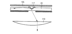
別の態様において、大面積照明器具、たとえば、隅照明大面積照明器具は、上述したような光源と、マトリックス内に埋め込まれている複数のナノ粒子を備え、青色よりも赤色においてより大きい直接透過、および、赤色よりも青色においてより大きい拡散透過を可能にするように構成されている色拡散層とを備え、色拡散層は、特に、コリメート光によって照明されるように位置決めされ、または、コリメーションユニットの入力側および/もしくはコリメーションユニットの出力側の下流のような、光源領域の下流に位置決めされる。 In another embodiment, a large area luminaire, such as a corner luminaire, has a light source as described above and multiple nanoparticles embedded in a matrix, with greater direct transmission in red than in blue. , And a color diffuse layer configured to allow greater diffuse transmission in blue than red, the color diffuse layer being particularly positioned or collimated to be illuminated by collimated light. It is positioned downstream of the light source area, such as downstream of the input side of the unit and / or the output side of the collimation unit.
照明器具のいくつかの実施形態において、色拡散層は、入射光によって照明されるように、光源の発光面に設けられる裏側を有するパネルとして提供することができ、特に、コリメーションユニットの間には空隙があってもよく、かつ/または、コリメーションユニットは、第1のコリメート素子層と第2のコリメート素子層とを備えることができ、色拡散層は、第1のコリメート素子層と第2のコリメート素子層との間に位置決めすることができ、または、コリメーションユニットは、第1のコリメート素子層と、第1のコリメート素子層の下流に位置し、マトリックスおよび複数のナノ粒子を備える第2のコリメート素子層とを備えることができ、または、コリメーションユニットは、コリメート光放出領域と関連付けられている表面によって形成される発光面に施与される、マトリックスおよび複数のナノ粒子を有するコーティングを含むことができる。 In some embodiments of the luminaire, the color diffusion layer can be provided as a panel with a backside provided on the light emitting surface of the light source so that it is illuminated by incident light, especially between collimation units. There may be voids and / or the collimation unit may include a first collimating element layer and a second collimating element layer, and the color diffusion layer may include a first collimating element layer and a second collimating element layer. A second collimating unit, which can be positioned between the collimating device layer or is located downstream of the first collimating device layer and the first collimating device layer, comprises a matrix and a plurality of nanoparticles. A collimating device layer can be provided, or the collimation unit comprises a coating with a matrix and multiple nanoparticles applied to the light emitting surface formed by the surface associated with the collimated light emitting region. Can be done.
従属請求項として1つまたは複数の独立請求項のために挙げられている特徴が、本明細書において開示されている、または、特許請求の範囲においてリストされている他の態様に等しく適用されることに留意されたい。本開示の他の特徴および態様は、以下の説明および添付の図面から明らかになるであろう。 The features listed for one or more independent claims as dependent claims apply equally to other aspects disclosed herein or listed in the claims. Please note that. Other features and aspects of the disclosure will become apparent from the following description and accompanying drawings.
以下は、本開示の例示的な実施形態の詳細な説明である。詳細な説明において説明されており、図面に示されている例示的な実施形態は、本開示の原理を教示するように意図されており、当業者が、多くの異なる環境において、多くの異なる用途のために、本開示を実施および使用することを可能にする。それゆえ、例示的な実施形態は、特許保護の範囲の記載を限定するようには意図されておらず、そのように解釈されるべきではない。むしろ、特許保護の範囲は、添付の特許請求の範囲によって定義されるものとする。 The following is a detailed description of the exemplary embodiments of the present disclosure. The exemplary embodiments described in the detailed description and shown in the drawings are intended to teach the principles of the present disclosure, and those skilled in the art will appreciate many different uses in many different environments. Allows this disclosure to be implemented and used for the purposes of. Therefore, the exemplary embodiments are not intended to limit the description of the scope of patent protection and should not be construed as such. Rather, the scope of patent protection shall be defined by the appended claims.
本開示は、部分的に、場合によっては円対称放出(円錐内の光放出など)で、非常に小さいビーム発散(4°未満など)で光ビーム放出をもたらす出力を有する(薄型)導光体(本明細書においては導波路手法とも参照される)の構成に関する態様に基づく。 The present disclosure is a (thin) light guide having an output that, in some cases, is circularly symmetric emission (such as light emission within a cone) and results in light beam emission with a very small beam emission (such as less than 4 °). It is based on an aspect relating to the configuration (also referred to herein as a waveguide technique).
たとえば、本開示は、部分的に、導波路手法が以下の態様に対処し得るという認識に基づく。効率、すなわち、光をいかに効率的に導光ユニットへと結合することができるか、および、導光ユニットから誘導することができるか、および、導光ユニットから外方に結合することができるか。(材料、反射面などの)吸収および損失(散乱、表面の欠陥、スプリアス反射)が光出力を大きく低減し得るため。コリメーション、すなわち、得られるビーム発散を非常に小さくしながら、いかに導光ユニットから光を抽出することができるか。本明細書において、コリメーションまたはコリメートという用語は、特定の実施形態およびたとえば照明器具実施態様に対応して発散の低い光を指すものとして理解されることに留意されたい。そのような実施形態において、光源から放出される低発散ビームは、4°未満、たとえば2°などの、5°(未満)の範囲内の全幅ビーム角度を有してもよく、一方、他の実施形態では、4°未満、たとえば2°などの、7°などの10°(未満)の範囲内であってもよい。 For example, the present disclosure is based in part on the recognition that the waveguide approach can address the following aspects: Efficiency, i.e., how efficiently light can be coupled to and guided from the light guide unit, and whether light can be coupled outward from the light guide unit. .. Because absorption and loss (scattering, surface imperfections, spurious reflections) (of materials, reflective surfaces, etc.) can significantly reduce light output. How can light be extracted from the light guide unit while collimating, i.e., obtaining very small beam divergence? It should be noted that in the present specification, the term collimation or collimation is understood to refer to low divergence light corresponding to a particular embodiment and, for example, a luminaire embodiment. In such embodiments, the low divergence beam emitted from the light source may have a full width beam angle within the range of 5 ° (less than), such as less than 4 °, eg 2 °, while other In embodiments, it may be in the range of less than 4 °, such as 10 ° (less than) such as 7 °, such as 2 °.
たとえば、上記態様に関して、本発明者らは、とりわけ、光に±θ、θは最大でもTIR角度の余角(TIR角度はPMMAの場合、n=1.4936を考慮して約42°)、の誘導方向に対する角度範囲内で導光ユニット内にビームを伝播させる代わりに、光が、より狭い角度の扇形で導光ユニットへと結合することができることを認識した。たとえば、誘導媒質内で、扇形は、±10°、またはさらには±5°、またはさらにはそれ未満など、±15°にわたって拡散してもよい。扇形は、扇が導光体許容範囲の縁部に近接するような角度方向を中心としてもよい。本発明者らは、導光ユニット内を伝播する光が、光抽出機構が(たとえばアレイ構造に)編成されている表面と相互作用する確率が増大することを認識した。 For example, with respect to the above aspects, the present inventors, in particular, ± θ for light, θ is the margin of the TIR angle at the maximum (in the case of PMMA, the TIR angle is about 42 ° in consideration of n = 1.4936). Instead of propagating the beam into the light guide unit within an angular range with respect to the guiding direction of the light, it was recognized that light could be coupled to the light guide unit in a fan shape with a narrower angle. For example, in the induction medium, the sector may diffuse over ± 15 °, such as ± 10 °, or even ± 5 °, or even less. The fan shape may be centered in an angular direction such that the fan is close to the edge of the light guide body allowable range. We have recognized that the light propagating within the light guide unit is more likely to interact with the surface on which the light extraction mechanism is organized (eg, in an array structure).
その上、本発明者らは、完全な平面導光ユニットを考慮する代わりに、導光ユニットが、一例の平行な「ストリップ」を含む(ストリップに分割する)ことができることを認識した。各ストリップは、それらの極端部において、一方または両方の端部に位置決めされているLED光源からの一次光を受ける。抽出機構は、ストリップに沿った単一ラインアレイであってもよい。また、ストリップ構成は、表面導光ユニット内を伝播する光が、光抽出機構が位置決めされている表面と相互作用する確率を増大させる。 Moreover, we have realized that instead of considering a perfect planar light guide unit, the light guide unit can include (split into strips) an example of parallel "strips". Each strip receives primary light from an LED light source located at one or both ends at their extremes. The extraction mechanism may be a single line array along the strip. The strip configuration also increases the probability that the light propagating within the surface light guide unit will interact with the surface on which the light extraction mechanism is positioned.
概して、本発明者らは、導光ユニットの抽出機構と相互作用する確率を増強し、したがって、導光体のボリューム内部の光線の経路を低減するソリューションを実現した。これはさらに、材料および導光体極端部(100%反射性ではない)からの吸収を低減する。 In general, we have realized a solution that increases the probability of interacting with the extraction mechanism of the light guide unit and thus reduces the path of light rays inside the volume of the light guide. This further reduces absorption from the material and light guide extremes (not 100% reflective).
その上、本発明者らは、導光体内を伝播する光の入力スペクトルを適切に調整することによって、吸収に起因する出力スペクトルにおける色度ずれを補償することができることを認識した。 Moreover, the present inventors have recognized that by appropriately adjusting the input spectrum of the light propagating in the light guide body, the chromaticity deviation in the output spectrum due to absorption can be compensated.
以下において、本明細書において開示されている光源および照明器具の様々な態様の基礎を形成する、太陽−天空の様な照明の概念の文脈におけるエテンデュ保存則の背景考慮事項が与えられる。 In the following, background considerations of the Etendu conservation law in the context of the concept of lighting such as sun-heaven, which form the basis of various aspects of the light sources and luminaires disclosed herein, are given.
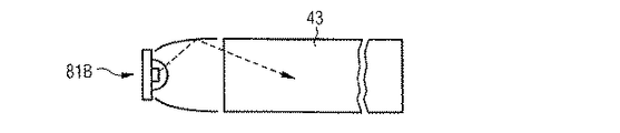
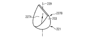
図1を参照すると、太陽1は、地球から149,600,000km離れており、直径は1,391,684kmである。その結果、地表面(例示的に窓3によって示されている)における直接太陽放射のおおよその全幅ビーム角は約0.53°になる。本出願人の上記で引用されている特許開示に記載されているように、地球における太陽からの光は、高強度光源5を適切に設計されたレイリー状作用拡散器7と組み合わせることによって再現することができる。直接太陽光を近似するように設計されている標準的な2’(0.61m)x4’(1.22m)の開口(面積:0.74m2)を有する光源を仮定すると、光源のエテンデュは、≦0.74m2πsin(0.53/2)2sr〜50mm2srであると推定される。光源が単一であり、ランバート円形発光器をもたらすチップオンボード(COB)型発光ダイオード(LED)に基づくとすると、許容可能な発光面積は50mm2sr/πsr=約16mm2になり、これは、LEDの発光面(LES)直径が4.5mmになることを意味する。
Referring to FIG. 1, the
2’x4’開口からの標準的な光出力は通常、少なくとも3000lmである(DesignLights Consortium(商標)製品品質基準、表4:一次利用要件参照)。妥当なレベルの光出力をもたらすために、また、妥当なシステム光学損失を考慮に入れると、4.5mm LESより大型のCOB LEDを選択する必要があり得る。たとえば、Nichia CorporationのNFDWJ130Bは、14.6mmのLES直径で6000lm超を提供することができ、または、167mm2πsr=526mm2srのエテンデュを提供することができる。エテンデュ制約に起因して、そのような光源は、上記開口サイズ、すなわち、直接太陽放射の開口よりも大きいが、依然として非常に狭く、可能性として太陽照明を模倣するには十分な開口サイズを仮定すると、最良で0.86°のビーム半角発散を達成し得る。 The standard light output from a 2'x4' aperture is typically at least 3000 lm (see DesignLights Consortium ™ Product Quality Standards, Table 4: Primary Usage Requirements). It may be necessary to select COB LEDs larger than 4.5 mm LES in order to provide a reasonable level of light output and taking into account reasonable system optical losses. For example, Nichia Corporation's NFDWJ130B can provide more than 6000 lm with a LES diameter of 14.6 mm, or can provide an etendu of 167 mm 2 π sr = 526 mm 2 sr. Due to the Etendu constraint, such a light source is larger than the aperture size, i.e., the aperture of direct solar radiation, but still very narrow, assuming an aperture size that is potentially sufficient to mimic solar illumination. Then, a beam half-angle divergence of 0.86 ° can be achieved at the best.
照明システムで使用するためにCOB LEDのランバート光出力をコリメートすることは、本明細書においてはそれぞれCPCレンズおよびTIRレンズとしても参照される、レンズもしくは複合放物面型集光器(CPC)または内部全反射(TIR)光学素子のような既知のコリメート光学ソリューションに基づき得る。全CPCを用いる場合、光学素子寸法は、関係L=cot(β_in/2)(a+b)/2によって決定され、Lは光学素子長であり、aおよびbは入力面および出力面の直径であり、β_in/2は、CPC内の最大許容発散半角である。このとき、CPCを出る最大半角β_out/2は、n sin(β_in/2)=sin(β_out/2)によって与えられる。エテンデュ保存則から、CPCの出力面の面積は約1/sin(0.86)2=入力面の面積の約4400倍であり、または直径が約1mである。光学素子が2’x4’開口にはやや大きすぎることを無視すると、CPCレンズの長さは実際に実現可能なものを超えるものになる。 Collimating the Lambert light output of a COB LED for use in a lighting system is also referred to herein as a CPC lens and a TIR lens, respectively, as a lens or composite surface condenser (CPC) or It can be based on known collimated optical solutions such as internal total internal reflection (TIR) optics. When all CPCs are used, the optic dimensions are determined by the relationship L = cot (β_in / 2) (a + b) / 2, where L is the optical element length and a and b are the diameters of the input and output surfaces. , Β_in / 2 is the maximum permissible divergence half-width in CPC. At this time, the maximum half-width β_out / 2 leaving the CPC is given by n sin (β_in / 2) = sin (β_out / 2). According to the conservation law of Etendu, the area of the output surface of the CPC is about 1 / sin (0.86) 2 = about 4400 times the area of the input surface, or the diameter is about 1 m. Ignoring that the optics are a little too large for a 2'x4' aperture, the length of the CPC lens will exceed what is actually feasible.
本発明者らは、光がLEDから放出される総面積(わずか約170mm2)が、開口の面積(0.74m2)よりもはるかに小さいことに気付いた。図1に示すように、ともに太陽のシミュレーションを達成する複数の発光ユニット11からなるアレイを備える光学系を形成することができる。レイアウトの凝縮を示す中間ステップとして、少数の光源(ここでは4つの光源9)を有する構成が、図1に示されている。同様の概念が、参照により本明細書に組み込まれる上記で引用した特許文献4に開示されている。
We have noticed that the total area of light emitted from the LED (only about 170 mm 2 ) is much smaller than the area of the aperture (0.74 m 2 ). As shown in FIG. 1, it is possible to form an optical system including an array of a plurality of light emitting
多数の発光ユニット11を有する実施形態の場合、任意の1つの発光源は光学系の発光面の総面積よりもはるかに小さいため、単一CPCレンズの事例に対して厚さは低減されるであろう。
In the case of an embodiment having a large number of light emitting
上述したエテンデュに基づく設計考慮事項に従って、図2Aは、CPCレンズの長さ対個々の光源直径の依存関係を示す。依存関係は例示的に、0.5°、1°、2°、および4°の標的ビーム発散について与えられる。この依存性は、本明細書において開示されている直接太陽光照明器具の設計において考慮される。たとえば、図2Aは、光源領域の50μmの直径が、約120mmのCPC長による2°のビーム発散を可能にし得ることを示す。それらの寸法はすでに、全体的な厚さが6インチ(152mm)よりも小さい平坦な照明器具システムの設計の可能性を示しており、これは費用(部品表、BOM)および設置の観点から非常に魅力的である。 According to the design considerations based on Etendu described above, FIG. 2A shows the dependency between the length of the CPC lens and the diameter of the individual light sources. Dependencies are exemplified for target beam divergence of 0.5 °, 1 °, 2 °, and 4 °. This dependency is taken into account in the design of the direct solar luminaires disclosed herein. For example, FIG. 2A shows that a 50 μm diameter of the light source region can allow a 2 ° beam divergence with a CPC length of about 120 mm. Their dimensions already show the possibility of designing a flat luminaire system with an overall thickness of less than 6 inches (152 mm), which is very costly (Bill of Materials, BOM) and installation. It is attractive to.
図2Bに示すように、全CPC(それぞれのコリメーションを可能にするものとしてCPCのみを考慮する)を、発散角が大きい(30°またはさらには45°以上など)CPCおよびフレネルレンズのようなコリメートレンズを含むコリメート光学素子の組合せ(本明細書においてはCPCレンズコリメータとして参照される)と置き換えることによって、コリメーションユニットの全長を大幅に短縮することができる。この場合、コリメーションの一部がコリメーションレンズによって実施されるため、CPCの制限された集光効果が許容可能である。たとえば、図2Aに関連して上述したようなコリメートユニットに必要な長さは120mmから約8mmに低減され、それによって、市場において非常に魅力的である、さらにより低いプロファイルの太陽/天空照明器具が可能になる。 As shown in FIG. 2B, all CPCs (considering only CPCs as allowing each collimation) are collimated with large divergence angles (such as 30 ° or even 45 ° or more) and Fresnel lenses. By replacing with a combination of collimating optical elements including a lens (referred to herein as a CPC lens collimator), the overall length of the collimation unit can be significantly reduced. In this case, since part of the collimation is performed by the collimation lens, the limited focusing effect of the CPC is acceptable. For example, the length required for a collimating unit as described above in connection with FIG. 2A has been reduced from 120 mm to about 8 mm, which makes it a very attractive on the market, even lower profile sun / sky luminaires. Becomes possible.
図2Cにおいて、全CPCレンズの直径対光源サイズおよびビーム発散の依存関係が示されている。同様の寸法が、エテンデュ保存則の考慮事項に照らして上述したCPCレンズコリメータに適用されよう。この情報は、コリメーションユニットの下流のコリメート光放出領域の予測面積をもたらす。本発明者らは、主要な狭いビームの外部の領域からの迷光または光のない領域(すなわち、コリメート光放出領域の周囲の非コリメート光または暗い領域)が、深度の印象および太陽光のシミュレーションに悪影響を及ぼし得るため、この情報を使用することが重要であると認識した。そのような迷光は、光学素子の縁部において発生し得る。したがって、本発明者らは、迷光のピッチまたはスケールが、コリメート光学素子レンズ直径に結びつけられると認識した。具体的には、迷光は、コリメーション光学素子のピッチに関連付けられる輝度周期性によって知覚可能になり得る(ただし、これに限定されるものではない)。 In FIG. 2C, the dependency between diameter vs. light source size and beam divergence of all CPC lenses is shown. Similar dimensions will apply to the CPC lens collimator described above in light of the considerations of the Etendu conservation law. This information provides a predicted area of the collimated light emission region downstream of the collimation unit. We have found that areas without stray or light from the outer regions of the major narrow beam (ie, non-colimated or dark regions around the collimated light emitting region) are used for depth impressions and sunlight simulations. We recognize that it is important to use this information as it can have adverse effects. Such stray light can occur at the edges of the optics. Therefore, we have recognized that the pitch or scale of stray light is tied to the collimating optic lens diameter. Specifically, stray light can be perceptible by the luminance periodicity associated with the pitch of the collimation optics (but not limited to).
したがって、図2Aおよび図2Bの態様に加えて、図2Cの教示を使用して、本明細書において開示されている原理による太陽光照明器具を設計することができる。特に、迷光が十分に小さいピッチにわたって発生するシステムを設計することができる。たとえば、1m〜5mのような一般的な観察距離について、本発明者らは、数ミリメートル以下のピッチにある迷光であれば、無限遠点において発生する「太陽」の像の見た目をはっきりとわかるほど損なうものではないことに気付いた。これは、太陽をシミュレートするときに重要な特徴である。図2Cは、2°のビーム発散について、約50μm直径の光源サイズによって、2.9mmのCPC出口直径を達成することができることを示している。同様に、約100μm直径の光源サイズは、5.8mmのCPC出口直径を達成することができる。環境によっては、より小さい(エレベータ:数十センチメートル〜約1メートル)またはより大きい(大広間:最大10m以上)の観察距離が生じる場合があり、小さい観察距離は、光学設計の観点からより困難を伴うことに留意されたい。 Therefore, in addition to the aspects of FIGS. 2A and 2B, the teachings of FIG. 2C can be used to design solar luminaires according to the principles disclosed herein. In particular, it is possible to design a system in which stray light is generated over a sufficiently small pitch. For a typical observation distance, for example 1 m to 5 m, we can clearly see the appearance of the "sun" image that occurs at point at infinity if the stray light is at a pitch of a few millimeters or less. I realized that it wasn't as damaging as it was. This is an important feature when simulating the sun. FIG. 2C shows that for a 2 ° beam divergence, a CPC outlet diameter of 2.9 mm can be achieved with a light source size of about 50 μm diameter. Similarly, a light source size of about 100 μm diameter can achieve a CPC outlet diameter of 5.8 mm. Depending on the environment, smaller (elevator: tens of centimeters to about 1 meter) or larger (large hall: up to 10 m or more) observation distances may occur, and small observation distances make it more difficult from the viewpoint of optical design. Please note that it accompanies.
上記から、たとえば、側方範囲において50μm〜100μm程度の光源サイズが、直接太陽光をシミュレートし、適度に薄く、可能性として低い費用で製造することができる照明器具を提供するための基礎を形成することができる。しかしながら、LEDは一般的に、200μmよりも大きいLES寸法を有する。2°のビーム発散を目標とする200×200μm2のLEDチップソリューションでさえ、全CPCコリメーションユニットについて0.5mよりも厚い照明器具をもたらし得、約1cmの距離にわたる迷光空間変動を有し(CPC出口直径のサイズに対応し、したがって、本質的に、光源間のピッチを設定する)、これは太陽シミュレーション効果を低減するおそれがある。したがって、より小さい光源またはより小さい光源領域が望ましい。 From the above, for example, a light source size of about 50 μm to 100 μm in the lateral range provides the basis for providing a luminaire that directly simulates sunlight and can be reasonably thin and potentially inexpensive to manufacture. Can be formed. However, LEDs generally have LES dimensions greater than 200 μm. Even a 200 x 200 μm 2 LED chip solution targeting 2 ° beam divergence can result in luminaires thicker than 0.5 m for all CPC collimation units and has stray spatial variation over a distance of about 1 cm (CPC). Corresponds to the size of the outlet diameter and therefore essentially sets the pitch between the light sources), which can reduce the solar simulation effect. Therefore, a smaller light source or a smaller light source region is desirable.
本発明者らは、本明細書においては抽出器としても参照される、下方変換および/もしくは散乱機構ならびに/または反射機構を利用することによって、LEDのような光源を1つの形状因子から別の形状因子へと変換することが可能であることを認識した。例示的な抽出器は、発光下方変換蛍光体化合物のディスクである。たとえば、発光下方変換蛍光体化合物の粒子を適切な結合剤(たとえば、シリコーン)に混合して、ディスクの形態で表面上に(たとえば、ディスペンサ機械によって)施与することができる。一次発光ユニット(たとえば、LEDまたはレーザダイオード、LD)からの光をディスク上に方向付ける/落とすことができる。その後、下方変換蛍光体化合物のディスク自体が、新たな光源になることができる。概して、そのような新たな光源は、本明細書においては、一次光源(本明細書においては発光ユニットとしても参照される)の光によって励起される局在化光源領域として参照される。その局在化光源領域は、上述した薄型光学構造におけるコリメーションにとっての所望のサイズを有することができる。 We use a downward transformation and / or scattering mechanism and / or reflection mechanism, which is also referred to herein as an extractor, to separate a light source such as an LED from one shape factor. It was recognized that it can be converted into a shape factor. An exemplary extractor is a disk of luminescent downward-converting fluorophore compound. For example, particles of a luminescent down-converting fluorophore compound can be mixed with a suitable binder (eg, silicone) and applied onto the surface in the form of a disc (eg, by a dispenser machine). Light from a primary light emitting unit (eg, LED or laser diode, LD) can be directed / dropped onto the disk. After that, the disc itself of the downward conversion phosphor compound can become a new light source. In general, such a new light source is referred to herein as a localized light source region that is excited by the light of a primary light source (also referred to herein as a light emitting unit). The localized light source region can have the desired size for collimation in the thin optical structure described above.
適切な下方変換材料は、蛍光体、蛍光体化合物、有機発光材料、半導体材料、および半導体ナノ粒子(「量子ドット」など)を含む。一般的な下方変換材料のリストが米国特許出願公開第2015/0049460号明細書に開示されており、その一部を下記の表Iに例示的に列挙する。 Suitable downward conversion materials include phosphors, phosphor compounds, organic light emitting materials, semiconductor materials, and semiconductor nanoparticles (such as "quantum dots"). A list of common down-conversion materials is disclosed in US Patent Application Publication No. 2015/0049460, some of which are exemplified by Table I below.
例示的な実施形態において、下方変換蛍光体化合物のディスクは、導光板(LGP)のいずれかの面に堆積されてもよい。LGPは一般的に、フラットパネルディスプレイ業界で使用されており、それらは、その縁部に適切に結合されている一次光源を含み得る。しかしながら、それらのフラットパネルディスプレイは、光放出のための高密度の内蔵光抽出または光散乱機構を含み得る(たとえば、それらの機構のサイズは、最近傍間の距離に相当する(かつ、本開示のものと比較してそれほど小さくはない))。対照的に、本明細書において開示されている概念のLGPは、一次光源からの光を、局在化光源領域(たとえば、ディスク)の特定の抽出位置へと誘導するように構成されている。 In an exemplary embodiment, the disc of the down-conversion fluorophore compound may be deposited on any surface of the light guide plate (LGP). LGPs are commonly used in the flat panel display industry and may include primary light sources that are properly coupled to their edges. However, those flat panel displays may include a high density built-in light extraction or light scattering mechanism for light emission (eg, the size of those mechanisms corresponds to the distance between the nearest neighbors (and the present disclosure). Not so small compared to the one)). In contrast, the concept LGP disclosed herein is configured to direct light from a primary light source to a particular extraction location in a localized light source region (eg, a disk).
上記の例示的な実施形態において、また、LGPの縁部が(たとえば、反射薄膜を使用して)反射性にされることを条件として、LGP内の光は、ディスクに行き当たるときに実質的にとらえられたままであり得る。その後、ディスクからの二次(下方変換)光(存在する場合)および散乱された一次光が、多かれ少なかれランバート放射パターンで放出され、これは、その光の相当の割合が、ディスクにおいて直接的に、または、反対側でLGPから逃げるであろうことを意味する。その光は、ディスクのサイズによって決定される光源サイズと関連付けられよう。多くのそのようなディスクが提供され得ると仮定すると、縁部においてLGPに結合される一次光源からの光は、非常に小さいディスクからなるアレイから発する光に変換され得る。 In the exemplary embodiments described above, and provided that the edges of the LGP are made reflective (eg, using a reflective thin film), the light within the LGP is substantially when it hits the disc. Can remain trapped in. The secondary (downward conversion) light (if present) and the scattered primary light from the disc are then emitted in a more or less Lambertian radiation pattern, which means that a significant proportion of that light is directly on the disc. , Or means that you will escape from the LGP on the other side. The light will be associated with a light source size that is determined by the size of the disc. Assuming that many such discs can be provided, the light from the primary light source coupled to the LGP at the edges can be converted to light from an array of very small discs.
上記例示的な実施形態を拡張して、小さいディスクは、コリメート素子のアレイ、たとえば、上述したようなCPCもしくはCPCレンズコリメータ、またはTIRレンズもしくはTIRレンズ−レンズコリメータに結合することができ、それによって、太陽光をシミュレートするコンパクトな照明器具を形成する。特に、コリメート素子の出力面積(円形状の場合は直径)が、光源の発光面にわたる光の均一で均質な放出を保証するための、LPGに適用される抽出器機構/ディスクのピッチを設定する。コリメート素子の入力面積は、それぞれの光源領域から相当量の光(たとえば、80%超、またはさらには90%超などの、50%超)を受けるように構成されている。 Extending the above exemplary embodiment, the small disc can be coupled to an array of collimating elements, such as a CPC or CPC lens collimator as described above, or a TIR lens or TIR lens-lens collimator. , Form a compact luminaire that simulates sunlight. In particular, the output area of the collimating element (diameter in the case of a circular shape) sets the extractor mechanism / disk pitch applied to LPG to ensure uniform and homogeneous emission of light across the light emitting surface of the light source. .. The input area of the collimating element is configured to receive a significant amount of light (eg, greater than 80%, or even greater than 90%, greater than 50%) from each light source region.
上記の例示的な実施形態において、下方変換蛍光体化合物は、太陽のような光スペクトルをもたらすように選択および調整することができる。しかしながら、本発明者らは、様々な色の複数の光源を組み合わせることによってそれぞれの太陽のようなスペクトルを生成することができる場合には、下方変換材料は省いてもよいことをさらに認識した。たとえば、一次光源は、青色、緑色、赤色またはさらには白色の発光LEDを含み得る。この場合、光抽出器は、LGPの透過を規定の局在化された様式で損なう粗面領域、または、屈折率が変化する領域のような、散乱機構であり得る。これによって、異なる色の光源の均一な光混合の手段を提供することができ、極端に小さい形状因子においては、上記の教示と組み合わせて、色調整の選択肢を伴って非常に発散の狭い光ビームを実現するようにできることを本発明者らは認識した。たとえば、一次光源の相対光出力は、色および/または強度における振幅またはパルス幅変調によって変えることができる。いくつかの実施形態において、散乱中心の効果と下方変換材料の効果とを組み合わせることさえできる。後者は、「量子ドット」と呼ばれることが多い半導体ナノ粒子の場合のように、下方変換材料が本質的に散乱性でない場合に有用であり得る。 In the above exemplary embodiments, the down-converted fluorophore compound can be selected and adjusted to provide a sun-like light spectrum. However, we have further recognized that the down-conversion material may be omitted if the combination of multiple light sources of different colors can produce a respective sun-like spectrum. For example, the primary light source may include blue, green, red or even white light emitting LEDs. In this case, the light extractor can be a scattering mechanism, such as a rough surface region that impairs the transmission of LGP in a defined localized manner, or a region where the refractive index changes. This can provide a means of uniform light mixing of light sources of different colors, and in extremely small shape factors, in combination with the teachings above, a very narrow divergence light beam with color adjustment options. The present inventors have recognized that the above can be realized. For example, the relative light output of a primary light source can be varied by amplitude or pulse width modulation in color and / or intensity. In some embodiments, the effect of the scattering center and the effect of the downward transform material can even be combined. The latter can be useful when the down-conversion material is not essentially scatterable, as in the case of semiconductor nanoparticles, often referred to as "quantum dots".
エテンデュ保存則を仮定することによって、入力面の面積と出力面の面積との間の比、たとえば、後述するような、光源領域の(組み合わせた)面積と、導光体によって被覆されているそれぞれの面積(たとえば、導光パネルの主前面の面積または導光ストリップ構成の場合は開口サイズ)との間の比は、入力面および出力面に応じた光の立体角の間の比(またはその逆数)である(r=(0.5*sinα_out)2/n2(0.5*sinα_in)2)。 By assuming the Ettendu Conservation Law, the ratio between the area of the input surface to the area of the output surface, for example, the (combined) area of the light source region, as described below, and each covered by the light guide. The ratio to the area of (for example, the area of the main front surface of the light guide panel or the opening size in the case of a light guide strip configuration) is the ratio between the stereoscopic angles of light depending on the input and output surfaces (or its). (Inverse number) (r = (0.5 * sinα_out) 2 / n 2 (0.5 * sinα_in) 2 ).
以下において、それぞれ一次光源(導光体の外部)の入力発散、導光体内のそれぞれの入力発散、および2°および4°の標的出力発散について、比が示されている。導光体および全角度発散について1.493の反射率が考慮された。当業者には理解されるように、導光ユニット内の角度発散は、エテンデュ保存則の考慮事項のために適用される必要がある。その上、光源領域は導光体の前面にあるため、角分は入力面に均一に分散されると仮定される。いくつかの実施形態において、光源領域は必ずしも抽出相互作用の領域に対応しない場合があり(たとえば図5Bの反射構造117およびそれぞれの実施形態の説明を参照されたい)、それによって、角分はもはや均等に分散されないように展開され得ることに留意されたい。後者は、たとえエテンデュが保存される場合であっても、それぞれの光源領域の面積がエテンデュ保存則の考慮事項によって必要とされるよりも大きい理由の一例である。下記の概説に与えられる比は、可能性としてより大きい抽出相互作用の面積の代わりに小さい面積を参照する。
Below, the ratios are shown for the input divergence of the primary light source (outside the light guide), the respective input divergence inside the light guide, and the target output divergence of 2 ° and 4 °, respectively. A reflectance of 1.493 was considered for the light guide and all-angle divergence. As will be appreciated by those skilled in the art, angular divergence within the light guide unit needs to be applied due to the considerations of the Etendu conservation law. Moreover, since the light source region is in front of the light guide, it is assumed that the corners are evenly distributed on the input surface. In some embodiments, the light source region may not necessarily correspond to the region of extraction interaction (see, eg,

表から明らかなように、比は、導光体に結合される、使用される発散光を少なくすることによって増大することができる。したがって、比は、入力発散および標的出力発散に応じて決まり、指示されているパラメータについて0.1%未満〜10%、またはさらには最大16%の範囲内にある。ランバート未満の入力発散は特に、下方変換LEDのようなCPC結合を使用する白色発光一次光源に適用され、一方で、レーザダイオードと、コリメート素子の入口側の下方変換材料との組合せは基本的にランバート発光器に対応することに留意されたい。LEDベースの実施形態について、たとえば、最大10%の比が、所望の低発散光ビームをもたらす構成を可能にすることができる。 As is clear from the table, the ratio can be increased by reducing the divergence light used that is bound to the light guide. Therefore, the ratio depends on the input divergence and the target output divergence and is in the range of less than 0.1% to 10%, or even up to 16% for the indicated parameters. Input divergence below Lambert is particularly applied to white light emitting primary sources that use CPC coupling, such as down-conversion LEDs, while the combination of a laser diode and a down-conversion material on the inlet side of the collimating element is essentially. Note that it corresponds to the Lambert light source. For LED-based embodiments, for example, a ratio of up to 10% can allow configurations that result in the desired low divergence beam.
光源領域においてある種の事前コリメート光をもたらすことを可能にする実施形態において、上記で要約したエテンデュの考慮事項は、開始点として低減したエテンデュを含み得ることに留意されたい。したがって、当業者であれば、許容可能なビーム半角発散を依然として可能にするピッチのより小さい構成が可能であり得ることを認識するであろう。これは、たとえば、ファン低減LED(導光体における低い角度範囲をもたらす)、レーザダイオードおよび/または合焦抽出器を使用する実施形態に適用され得る。 It should be noted that in embodiments that allow certain pre-collimated light to be provided in the light source region, the etendu considerations summarized above may include reduced etendu as a starting point. Therefore, one of ordinary skill in the art will recognize that smaller pitch configurations may be possible that still allow acceptable beam half-width divergence. This may be applied, for example, to embodiments using fan-reduced LEDs (which provide a low angular range in the light guide), laser diodes and / or focus extractors.
以下において、まず、本明細書に開示されている概念に基づく照明器具の一般的な構成の概説を記載する。その後、光源、基礎となる導光ユニットへの光結合および導光ユニットからの光抽出のような部分の様々な実施形態が例示される。 The following first outlines the general configuration of a luminaire based on the concepts disclosed herein. After that, various embodiments of parts such as a light source, light coupling to the underlying light guide unit and light extraction from the light guide unit are exemplified.
図3Aおよび図3Bは、たとえば、建造物の部屋の壁23(天井または側壁)に取り付けることができるものとしての照明器具21を示す。照明器具21は、ともに太陽のような照明を可能にする光源25および色拡散層27を備える。具体的には、光源25が直接光ビーム29のアレイを提供し、その一部が色拡散層27によって天空様拡散光31に変換され、残りの部分が色拡散層27を通過し、壁23の窓を通じて降り注ぐ太陽光線として知覚される。
3A and 3B show, for example, a
概して、照明器具21は、例示的なマウントとして様々な構成要素をともに被覆および保持するハウジング33を備えることができる。図3Bに示すように、いくつかの実施形態において、ハウジング33は、照明器具21の開口35を境界することができ、当該開口を通じて、直接光ビーム29のアレイおよび天空様拡散光31が部屋に入ることができる。いくつかの実施形態において、照明器具21は、壁23の中に取り付けることができ、かつ/または、ハウジングが、側面および裏側のみを被覆するようにすることができる。
In general, the
電源および/または制御ユニット34をハウジング内に設けることができ、または、図3Bに示すように、ハウジング33の外部に位置決めすることができる。
The power supply and / or
図3Aおよび図3Bにおいて、光源25の例示的な内部構造の構成要素は、複数の発光ユニット41、導光ユニット43、およびコリメーションユニット45を含む。
In FIGS. 3A and 3B, the components of the exemplary internal structure of the light source 25 include a plurality of light emitting
具体的には、発光ユニット41は一次光源として機能し、発光方向49において導光ユニット43の少なくとも1つの側方結合面47を通じて導光ユニット43へと光を放出するように構成されている。発光方向49は、本明細書においては、図3Aにおいては2つの発光ユニットについて例示的に示されているように、複数の発光ユニット41のそれぞれから導光ユニット43までの方向として理解される。
Specifically, the
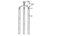
図3Aにおいて、発光ユニット41は、2つのサブグループ51Aおよび51Bにグループ分けされる。各サブグループ51Aおよび51Bについて、それぞれの発光ユニット41は、導光ユニット43のそれぞれの側面に沿って分散され、導光ユニット43の長手方向側面が延伸する方向に沿って光を発する。サブグループ51Aおよび51Bは、それぞれの基板53A、53Bに取り付けることができ、基板は、電源および/または制御ユニット34に接続されており、発光ユニット41のタイプに応じて強度および色スペクトルのような発光ユニット41の出力パラメータを制御するように構成されている電子デバイスを含むことができる。
In FIG. 3A, the
概して、導光ユニット43は、概して厚さ方向dTにおいて側方結合面47によって接続されている主前面55A、主後面55Bを有する。導光ユニット43は、主前面55Aと主後面55Bとの間の内部全反射(TIR)によって、少なくとも1つの結合側面において受けられる光を誘導するように構成されている。導光ユニット43は、たとえば、ハイインデックス導波路であってもよい。
Generally, the
理解されるように、導光ユニット43内で、光は反対の側面からそれぞれの他方の側面に向かって伝播し、他方の側面において、光の一部は反射し戻され得る。概して、導光ユニット43内の光分布は、発光ユニット41の位置、導光ユニット43への結合のタイプ、および、側面の内部全反射、吸収効果および反射のような導光ユニット43内の光伝播条件、ならびに、導光ユニット43から光を抽出するために与えられる光抽出に応じて決まる。
As will be appreciated, within the
図3Aの実施形態において、パネル状の形状の導光ユニット43が示されているが、下記に説明するように、三角形またはストリップ構成のような他の形状も可能であり得る。概して、導光ユニット43の厚さは、1mm〜5mm、または、特にストリップ構成においてはさらにそれ未満の範囲内であってもよい。
In the embodiment of FIG. 3A, the panel-shaped
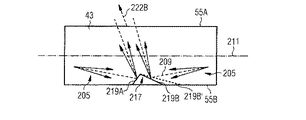
図3Aにおいて、5×3局在化光源領域57の格子が、例示的に示されている。しかしながら、概して最大数万個の多数の光源領域57が存在してもよい(たとえば、4°の最終的な発散のための2インチ×4インチパネル状の、88,000個の100μm抽出機構および2°の最終的な発散のための約22,000個の抽出機構からなる「発光器格子」)。局在化光源領域57において、光をコリメーションユニット45に入れるために、導光ユニット43から光が抽出される。光源領域57は、少なくとも開口35内で導光ユニット43にわたって均等に分散されている。たとえば、光源領域57は、発光方向49において等距離をおいて、非発光領域59にわたって分散している。光源25において、非光源領域59とは、導光ユニット43の主前面55Aのうち、基本的に光を照明に供しない領域である。たとえば、導光ユニット43は、基本的にその非光源領域59において光が漏出しないように構成されている。一切の光が、たとえば、何らかの散乱などによって引き起こされる漏れによって非光源領域59から導光ユニット43を出ない場合、その光は、強度が低いか、大きい角度範囲にわたって分散しているかのいずれかであり、それによって、光は、知覚に寄与しておらず、または、本明細書において開示されているようなバッフル構造によって遮断され得る。たとえば、非光源領域59からの全光束(パワー)は、下記に定義するように、すべての光源領域から発する光束の約10%以下、約5%以下、またはさらには約2%以下であってもよい。その上、非光源領域59の局部光束密度(平均)は、光源領域から放出される光束密度(平均)の、約1%以下またはさらにはそれを数等級下回るような、約3%以下であってもよい。隣接する光源領域間の距離は、たとえば、約3mm〜約6mmなど、0.5mm〜15mmの範囲内であってもよい(本明細書においては、通常、光伝播方向において存在するピッチ距離としても参照される。光伝播方向は、特に、導光ユニット、特に導光ストリップの長さ寸法の中心軸の方向と一致する)。各光源領域のサイズが小さいことに照らして、複数の光源領域57の面積と、主前面55Aの面積(または、非光源領域59の面積)との比は、たとえば、0.2%以下であってもよい。本明細書において開示されているストリップ構成に関して、非光源領域は、導光ストリップと関連付けられる区画、および、導光ストリップ間の領域を含むことができることに留意されたい。
In FIG. 3A, a grid of 5 × 3 localized
光伝播条件の何らかのタイプの変化の結果として、光が、光源領域57において主前面55Aを通過することになる。通過する光は、一次光、すなわち、発光ユニット41の光の一部分であってもよく、または、光は、たとえば、一次光と、蛍光体化合物もしくは量子井戸構造との相互作用によって生成される下方変換光であってもよい。例示的な実施形態は下記に説明される。言い換えれば、光源領域57は、光が散乱、反射、下方変換などに起因する非TIR条件を伴って導光ユニットを形成する壁/境界面に入射するという事実に起因して、または、導光ユニットを形成する壁/境界面の局部領域においてTIR条件を変更/除去することによってのいずれかで、領域を通過する光によって画定されると考えることができる。
As a result of some type of change in light propagation conditions, light will pass through the main
上記で示したように、複数の光源領域57と、主前面55Aの面積(または同様に、非光源領域59の面積)との比は、コリメート素子に与えられる光(たとえば、光源領域から発せられるものとしての)の角度分布、および、意図されるコリメーション角度に応じて決まる。したがって、比は、たとえば、2°または4°の固定コリメーション角度、および、導光ユニット内で誘導される光の角分(扇形)のような一次光条件について大きく異なり得る。コリメート素子に対するランバート入力光について、複数の光源領域57の面積と、主前面55Aの面積との比は、たとえば、0.5%または0.2%またはそれ以下であってもよい。しかしながら、光源領域が狭い立体角の光を発する事例については、複数の光源領域57の面積、したがって、比は、大規模な実施形態について、たとえば、最大10%またはさらには最大15%または16%と、大幅に増大することができる。例示的な光源領域は、(たとえば、出口側のコリメート素子の直径に対応する)10mmのピッチをおいて配置される、約3mmの直径を有してもよい。概して、コリメート素子に与えられている角度分布の角度と、意図されているコリメーション角度との間の比が小さくなるほど、光源領域の面積と主前面の面積との間の比は小さくなる。それらの考慮事項は、光学設計においてエテンデュが保存されると仮定している。
As shown above, the ratio of the plurality of
上記比の一般的な値は、言及されている0.2%のような0.5%未満、またはさらには0.1%未満であってもよい。さらなる例として、100μm光源領域および2.9mmコリメータ(ピッチ)について、コリメート素子間に「損失した」領域(図8Bの領域199など)を一切有しない完全な光源を仮定すると、比は単一のコリメート素子と同じであり、すなわち、7850μm2/8.41mm2(すなわち、約0.1%)である。
General values for the above ratios may be less than 0.5%, such as the 0.2% mentioned, or even less than 0.1%. As a further example, for a 100 μm light source region and a 2.9 mm collimator (pitch), assuming a complete light source with no “lost” regions between collimating elements (such as
概して、光源領域57のサイズは、100μmのような10μm〜500μmの範囲内の側方延伸を有してもよい。その上、光源領域57は、円形、楕円形、矩形、もしくは正方形の形状または原則として任意の形状を有してもよいが、形状は、遠距離場にある光源の外観の影響を受け得る。それとは対照的に、導光ユニット43の厚さ方向延伸は、1mm〜5mmの範囲内、場合によっては1mm未満であってもよい。光源領域57は、同じサイズまたは基本的に同様のサイズで設けられてもよい。複数のコリメート素子についてそのような光源領域57を設けることによって、コリメート素子の入力側において受けられる光について同様の入力条件を保証することができる。
In general, the size of the
概して、導光ユニットの非光源領域を通じた発光が回避され、または、少なくとも、天空太陽模倣の知覚を損なわないように低減される。 In general, light emission through the non-light source region of the light guide unit is avoided, or at least reduced so as not to impair the perception of sky-sun imitation.
したがって、コリメーションユニット45は、光源領域57から光を受け、概して、たとえば、太陽光を模倣するために数度の発散を有するコリメート光をもたらすように構成される。
Thus, the
コリメーションユニット45は、主前面55Aに沿って延伸し、導光ユニット43の形状、特に、光源領域57の分布および開口35の形状に適合されている形状を有する。
The
コリメーションユニット45は、光源領域57の格子に対応する複数のコリメート素子を備える。コリメーションユニット45、したがって、コリメート素子の厚さは、2mm〜15cmなど、1mm〜0.3mの範囲内であってもよい。
The
各コリメート素子は、複数の光源領域57のうちの1つに光学的に結合される。したがって、各コリメート素子は、それぞれの光源領域57から現れる光(基本的にはそれのみ)を受け、それぞれのコリメート光放出領域61からコリメート光を発するように構成される。コリメート光放出領域61は、たとえば、0.5mm〜50mmの範囲内の光源領域57のピッチ距離と同様の、0.2mm未満でさえあるダイオードレーザからの光のような、よくコリメートされた一次光に対する側方延伸を有することができる。コリメート光放出領域61は、光源25の発光面63を形成する。面63は、たとえば、コリメートユニットがレンズアレイ構造または反射性CPCアレイ構造から形成される実施形態において、連続面であってもよい。コリメートユニットが、たとえば、反射性CPCアレイ構造から形成される実施形態では、光コリメート領域61が表面構造とは関連付けられず、代わりに、CPCアレイ構造のそれぞれの出力面と関連付けられてもよいため、面63は表面でなくてもよい。
Each collimating element is optically coupled to one of a plurality of
コリメーションを実施するために、コリメート素子は、レンズおよび/またはCPCレンズのような1つまたは複数の光学素子を含んでもよい。コリメート素子はともに、たとえば、PMMA(導光ユニットおよび/または色拡散層のマトリックスに使用することもできる)のような透明材料のレンズ層/CPC構造を形成することができる。 To perform collimation, the collimating element may include one or more optical elements such as a lens and / or a CPC lens. Both collimating elements can form a lens layer / CPC structure of a transparent material, such as PMMA (which can also be used as a light guide unit and / or a matrix of color diffusion layers).
発光面63は、たとえば、発光領域61の間の境界(図3Aにおいては、レンズもしくは反射性CPCまたは反射性CPCの壁の間の遷移部または接合部のような、発光領域61を分離する格子線として示されている)にある、非発光領域65のそれぞれ小さい部分を含むことができる。
The
各発光領域61の放出は、広いスペクトル(たとえば、白色光)および主光ビーム伝播軸67を中心とした規定の小さい発散を有する指向性光であり、これは、色拡散層27を通過した指向性光のその部分について、図3Bに概略的に示されている。具体的には、放出される光は、放出立体角にわたって分散し、それによって、主光ビーム伝播軸67の方向に沿って伝播する光ビームを形成する。図3Bは、遠距離場における例示的に発散する(ゆるやかに発散する)直接光ビーム29を示す。遠距離場は、それぞれのコリメート素子によって生成される近接場、および、コリメート素子によって処理されている光に依存する。
The emission of each
遠距離場において、発散光ビーム29にわたる局所伝播方向、すなわち、指向性非拡散光の伝播方向は、伝播軸67に対する直接光ビーム29の断面内の位置に応じて変化する。具体的には、局所伝播方向69は、内側領域からの距離が増大するにつれて、主光ビーム伝播軸67に対して次第に傾いていく。例示的に、最も離れている局所伝播方向の最大角度α_out/2が図3Bに示されており、これは、直接光ビーム29の、たとえば2°または4°のビーム発散(本明細書においては、遠距離場におけるビーム全角発散または全角発散としても参照される)に対応する。単一光源領域の光ビーム29(たとえば、ただ1つの光源領域における切り換え)について、遠距離場はすでに、天井−床の距離に等しい距離(屋内照明器具−標的であってもよい)、または、さらにはより局在化された照明のためのより小さい距離において基本的に形成され得る。これは、光ビーム29を基本的に円形として示すことによって、図3Cに示されている。照明器具全体の主光ビーム(多くの光源領域から構成されており、したがって、はるかに大きい面積にわたって延在する)に関して、遠距離場は、たとえば、数十メートルとはるかにより大きい距離に形成されていると考えられ得る。遠距離場において、図3Cにおいて線72によって示されている基本的に矩形のスポットは、開口の形状の記憶を失うにつれて円形になる。主光ビームの遠距離場を形成するための距離は、光角度発散および照明器具サイズに応じて決まることに留意されたい。
In a long-distance field, the local propagation direction across the
均質な放出について、非発光領域65とコリメート光放出領域61との間の面積比は、光源25の発光面63にわたって基本的に一定である。そのような一定の比は、発光面63からの均質な発光に寄与することができる。その上、1つのコリメート光放出領域61からの放出は、コリメート光放出領域61内部で側方に完全に含まれている(十分に光っている)ものとして知覚されるように構成することができる。直接光ビーム29のビーム発散が対称であると仮定すると、このとき、光ビーム内から見る観察者によって、並置されたコリメート光放出領域61が、明るい円盤の像として知覚され、この直径は、コリメート光放出領域61に対応する「画素」のセットに分割されている、遠距離場内の全角発散に関連する。単一コリメート光放出領域61の寸法は、領域内の可能な光変調が、一般的な観察距離から見る観察者によって知覚される可能性が低くなるようなものであるべきである。
For homogeneous emission, the area ratio between the
図3Bにさらに概略的に示されているように、コリメーションユニット45は、特に隣接する、発光領域61の下流のコリメート素子の間の光の相互作用(本明細書においては、光源領域、およびコリメート素子を含む、個々の光ビーム生成光学シーケンス間のクロストークとしても参照される)を低減し、またはさらには回避するための、何らかのタイプのバッフル構造71を備えることができる。いくつかの実施形態において、バッフル構造71は、たとえば、吸光および/または暗色層/材料をコーティングされている、または、暗色仕上げを有する構造要素(たとえば、遮蔽板または光学素子の表面)であってもよい。
As more schematically shown in FIG. 3B, the
反射性構造ユニットの色拡散層に関して、本開示は、同じ出願人によって出願された国際公開第2009/156348号に開示されている光拡散器に関する。 With respect to the color diffusing layer of the reflective structural unit, the present disclosure relates to a light diffusing device disclosed in WO 2009/156348 filed by the same applicant.
これは、たとえば、サンドイッチの実施形態のような薄膜、コーティング、またはバルク材料内に複数の固体透明ナノ粒子が分散された、本質的に透明な固体マトリックスを備えることができる。本明細書では、「拡散層」、「ナノ拡散器」、および「色拡散層」という用語は、一般に、それらの(本質的に透明な)ナノ粒子を埋め込んだマトリックスを備える光学要素を示す。 It can include, for example, an essentially transparent solid matrix in which multiple solid transparent nanoparticles are dispersed within a thin film, coating, or bulk material as in a sandwich embodiment. As used herein, the terms "diffusing layer," "nanodiffusing layer," and "color diffusing layer" generally refer to optical elements that include a matrix in which their (essentially transparent) nanoparticles are embedded.
色拡散層は、原理的に、本質的に色分離を生じる同じメカニズムによって、(一般的には白色光などの)広いスペクトル帯域を有する入射光の異なる色成分を(色的に)分離することができる。レイリー散乱は、たとえば、天空光および太陽光のスペクトル分布特性を生成している。より具体的には、色拡散層は、可視白色光に曝されると、2つの異なる色成分、青色、すなわち青色または「冷たい」スペクトル部分が支配的な拡散された空のような光、および、青色が減少した成分、すなわち黄色または「暖かい」スペクトル部分を有する、透過された光が同時に存在する状態を再現することができる。 The color diffusion layer, in principle, separates (colorwise) different color components of incident light with a wide spectral band (generally white light, etc.) by the same mechanism that essentially results in color separation. Can be done. Rayleigh scattering, for example, produces spectral distribution characteristics for skylight and sunlight. More specifically, when the color diffuser is exposed to visible white light, it has two different color components: blue, a diffuse sky-like light dominated by blue, or "cold" spectral portions, and It is possible to reproduce the simultaneous presence of transmitted light, with a reduced blue component, i.e. a yellow or "warm" spectral portion.
照明器具21の色拡散層の透過特性を参照すると、その構造は、ナノ粒子に基づいて、青色よりも赤色においてより大きい透過、および、赤色よりも青色においてより大きい拡散散乱を含むような特定の光学特性を達成するようなものである。この光学特性は、本質的に、開口35の全範囲にわたって存在し得る。
With reference to the transmission characteristics of the color diffusion layer of
本明細書では、Standard Terminology of Appearance、ASTMインターナショナル、E284−09aで定義されているように、透過率は、一般に、所与の条件における入射光束に対する透過光束の比である。たとえば、拡散透過率は、入射光束に対する反射光束の比によって与えられるそれぞれの試料の特性であり、透過は、正透過角の方向を除く測定平面によって境界付けられた半球内のすべての角度におけるものである。同様に、正透過率は、非拡散角、すなわち、入射角の下での透過率である。本開示の文脈において、所与の波長および色拡散層上の所与の位置について、拡散透過率および正透過率は、主光ビーム伝播軸67に対応する入射角を有する非偏光入射光を対象とする。測定について、透過の測定のための検出器の角度サイズ、および入射ビームの開口角は、当業者には明らかな範囲内で選択可能である。特に、(白色光)低角拡散器を考慮する場合、たとえば、正透過の測定のための検出器の角度サイズ、および入射ビームの開口角は、センサが入射角の周りの円錐内の透過を有する光線を受け入れるように構成されるべきである。いくつかの実施形態では、0.9°の2倍の開口角が使用され得る。
As defined herein by Standard Terminology of Appearance, ASTM International, E284-09a, transmittance is generally the ratio of transmitted luminous flux to incident luminous flux under given conditions. For example, diffuse transmittance is a characteristic of each sample given by the ratio of reflected luminous flux to incident luminous flux, and transmission is at all angles within the hemisphere bounded by the measurement plane except in the direction of the positive transmission angle. Is. Similarly, the positive transmittance is the non-diffusion angle, that is, the transmittance under the angle of incidence. In the context of the present disclosure, for a given wavelength and a given position on the color diffusing layer, the diffusing and positive transmittances are for unpolarized incident light having an incident angle corresponding to the principal light
その上、透過光束は、すべての可能な入射方位角にわたって平均化される。拡散透過率および/または正透過率の測定が、照明器具の構成に関連する幾何学的制約または他の物理的制約によって妨げられる場合、当業者は、少なくとも1つの別個の色拡散層を形成し、その部分への透過率を直接測定することによって、上述した量を得ることができる。微視的な構造的特性の詳細については、たとえば、上述した公報国際公開第2009/156348号を参照されたい。しかしながら、微視的パラメータの異なる値が適用可能であり得る。たとえば、非散乱光に対してより多くの散乱光をもたらすパラメータを適用することができる。同様に、可能性のある迷光の可視性を最小化するか、または少なくとも低減する目的で、結果として知覚される色が完全な晴天の色から逸脱する可能性があるという事実にもかかわらず、拡散光に起因する色拡散層の輝度への寄与を増加させることを選好することができる。後者は、その中で生じる多重散乱の結果として彩度のレベルを低下させることによって引き起こされる可能性があり、多重散乱を引き起こす濃度未満の濃度でも引き起こされる可能性がある。
以下では、いくつかの微視的な特徴を例示的に要約する。
Moreover, the transmitted luminous flux is averaged over all possible incident azimuths. If the diffuse transmission and / or positive transmission measurement is hampered by geometric or other physical constraints associated with the construction of the luminaire, the person skilled in the art forms at least one separate color diffusion layer. , The above-mentioned amount can be obtained by directly measuring the transmittance to the portion. For more information on microscopic structural properties, see, for example, WO 2009/156348 described above. However, different values of microscopic parameters may be applicable. For example, parameters that result in more scattered light for non-scattered light can be applied. Similarly, despite the fact that the resulting perceived color may deviate from the perfect clear sky color in order to minimize or at least reduce the visibility of possible stray light. It may be preferred to increase the contribution of the diffused light to the brightness of the color diffuser layer. The latter can be caused by reducing the level of saturation as a result of the multiple scattering that occurs in it, and can also be caused at concentrations below the concentration that causes multiple scattering.
The following is an exemplary summary of some microscopic features.
色効果は、たとえば、10nm〜240nmの範囲内のサイズを有するナノ粒子に基づく。たとえば、平均サイズがその範囲内にあってもよい。 The color effect is based on nanoparticles having a size in the range of 10 nm to 240 nm, for example. For example, the average size may be within that range.
透明マトリックスと、マトリックスに対して異なる屈折率を有し、可視波長よりも(かなり)小さいサイズを有する透明ナノ粒子とを備える透明光学素子が、スペクトルの青色部分(青色)を優先的に散乱させ、赤色部分(赤色)を透過させることは、光散乱の原理からよく知られている。単一の粒子あたりの散乱効率の波長依存性が、波長λの1/10よりも小さいか、またはほぼ等しい粒子サイズのλ−4レイリー限界法則に近づく間、それぞれの許容可能な光学的効果は、ナノ粒子のサイズの上記範囲内にすでに達する可能性がある。一般に、より大きいサイズ、たとえば、波長の半分のサイズで、共振および回折効果が発生し始める可能性がある。 A transparent optic with a transparent matrix and transparent optics having a different refractive index to the matrix and a size (significantly) smaller than the visible wavelength causes the blue portion (blue) of the spectrum to be preferentially scattered. It is well known from the principle of light scattering that the red part (red) is transmitted. While the wavelength dependence of the scattering efficiency per single particle approaches the λ- 4 Rayleigh limit law of particle size less than or about equal to 1/10 of the wavelength λ, each acceptable optical effect , It is possible that the size of the nanoparticles will already reach the above range. In general, at larger sizes, such as half the wavelength, resonance and diffraction effects can begin to occur.
一方、単一の粒子あたりの散乱効率は、粒子サイズdが減少するとともに、d−6に比例して低下し、小さすぎる粒子の使用を不便にし、伝播方向に多数の粒子を必要とし、これは、許容される充填率によって制限される可能性がある。たとえば、厚い散乱層について、マトリックス内に埋め込まれるナノ粒子のサイズ(特に、それらの平均サイズ)は、20nm〜180nmなどの、10nm〜240nmの範囲内であってもよい。 On the other hand, the scattering efficiency per single particle decreases in proportion to d- 6 as the particle size d decreases, which makes it inconvenient to use particles that are too small and requires a large number of particles in the propagation direction. May be limited by the filling rate allowed. For example, for thick scattering layers, the size of the nanoparticles embedded in the matrix (particularly their average size) may be in the range of 10 nm to 240 nm, such as 20 nm to 180 nm.
いくつかの実施形態では、その範囲外の寸法のより大きい粒子がマトリックス内に設けられてもよいが、それらの粒子は、レイリー状の特徴に影響を与えず、たとえば、主光ビーム方向の周りに低角散乱円錐を形成することのみに寄与する可能性がある。たとえば、ナノ粒子よりも大きい寸法を有する粒子を備え、主光ビーム方向の周りに低角散乱円錐を形成することに寄与するようにサイズおよび密度を選択される低角散乱層は、別個の層として設けられてもよく、または、色拡散層内に組み込まれてもよい。 In some embodiments, particles larger in size outside that range may be provided in the matrix, but these particles do not affect Rayleigh features, eg, around the direction of the main light beam. May only contribute to the formation of low-angle scattering cones. For example, a low-angle scattering layer that has particles with dimensions larger than nanoparticles and whose size and density are selected to contribute to the formation of a low-angle scattering cone around the direction of the principal light beam is a separate layer. It may be provided as, or it may be incorporated in the color diffusion layer.
色効果は、さらに、埋め込みマトリックスの屈折率とは異なる屈折率を有するナノ粒子に基づく。散乱するために、ナノ粒子は、光散乱が起こることを可能にするために、マトリックス(ホスト材料とも呼ばれる)の屈折率nhとは十分に異なる実際の屈折率npを有する。たとえば、粒子の屈折率とホスト媒質の屈折率との間の比m(=np/nh)は、範囲0.7≦m≦2.1または0.7≦m≦1.9などの範囲0.5≦m≦2.5内であってよい。 The color effect is further based on nanoparticles having a refractive index different from that of the embedded matrix. To scatter, the nanoparticles have an actual index of refraction n p that is sufficiently different from the index of refraction n h of the matrix (also called the host material) to allow light scattering to occur. For example, the ratio m (= n p / n h ) between the refractive index of the particles and the refractive index of the host medium has a range of 0.7 ≦ m ≦ 2.1 or 0.7 ≦ m ≦ 1.9. It may be within the range 0.5 ≦ m ≦ 2.5.
色効果は、さらに、所与の方向に伝播する衝突光によって見られる単位面積あたりのナノ粒子の数、ならびに、体積充填率fに基づく。体積充填率fは、 The color effect is further based on the number of nanoparticles per unit area seen by the collision light propagating in a given direction, as well as the volume filling factor f. The volume filling factor f is
によって与えられ、ρ[メートル−3]は、単位体積あたりの粒子数である。fを増加させることによって、拡散層中のナノ粒子の分布は、そのランダム性を失う可能性があり、粒子の位置は、相関するようになる可能性がある。結果として、粒子分布によって散乱された光は、単一粒子の特性だけでなく、いわゆる構造因子にも依存する変調を受ける。概して、高い充填率の影響は、散乱効率をひどく減少させることである。その上、特に、より小さい粒子サイズについて、高い充填率はまた、散乱効率の波長依存性と、同様に角度依存性とに影響を及ぼす。f≦0.1などのf≦0.4、またはさらにはf=0.001などのf≦0.01の充填率で作業することによって、それらの「密充填」効果を回避することができる。 Given by, ρ [meter- 3 ] is the number of particles per unit volume. By increasing f, the distribution of nanoparticles in the diffusion layer can lose its randomness and the position of the particles can become correlated. As a result, the light scattered by the particle distribution undergoes modulation that depends not only on the properties of a single particle, but also on so-called structural factors. In general, the effect of high filling rates is to severely reduce scattering efficiency. Moreover, high fill rates also affect the wavelength dependence of scattering efficiency, as well as the angle dependence, especially for smaller particle sizes. By working with a filling factor of f ≦ 0.4 such as f ≦ 0.1 or even f ≦ 0.01 such as f = 0.001, their “dense filling” effect can be avoided. ..
色効果は、さらに、有効粒子直径D=dnhに依存して、色拡散層の単位面積あたりのナノ粒子の数Nに基づく。それによって、d[メートル]は、[T.C.GRENFELL、およびS.G.WARREN、「Representation of a non−spherical ice particle by a collection of independent spheres for scattering and absorption of radiation」、Journal of Geophysical Research104、D24、31,697−31,709(1999)]に定義されているように、球状粒子の場合には平均粒子直径として、非球状粒子の場合には体積−面積が同等の球状粒子の平均直径として定義された平均粒子サイズである。有効粒子直径は、メートルで与えられ、またはnmで指定される。
いくつかの実施形態では、
The color effect is further based on the number N of nanoparticles per unit area of the color diffusion layer, depending on the effective particle diameter D = dhn h . As a result, d [meter] becomes [T. C. GRENFELL, and S.M. G. WARREN, "Representation of a non-sphere particle by a collection of independence for scattering for scattering and scattering and absorption of radiation", Jour, 104 , In the case of spherical particles, it is the average particle size, and in the case of non-spherical particles, it is the average particle size defined as the average diameter of spherical particles having the same volume-area. The effective particle diameter is given in meters or specified in nm.
In some embodiments,
たとえば、純粋な晴天の存在をシミュレートすることを目的とする実施形態について、 For example, for an embodiment aimed at simulating the existence of pure clear sky.
正反射されたシーンの寄与を最小化することを目的とする他の実施形態では、 In other embodiments aimed at minimizing the contribution of a specularly reflected scene,
それらの物理的パラメータおよびそれらの一般的な相互作用に関しては、たとえば、国際公開第2009/156348号を再び参照されたい。 See again, for example, WO 2009/156348 for their physical parameters and their general interactions.
本明細書で開示される色拡散層の巨視的な光学特性は、以下の2つの量で説明され得る。 The macroscopic optical properties of the color diffusing layer disclosed herein can be explained by the following two quantities.
(i)拡散層が10nm〜240nmの範囲内のサイズを有するナノ粒子、すなわち、衝突する放射線の短波長を優先的に拡散させる原因となるナノ粒子を含まないという事実を除いて、散乱光の寄与を有しない色拡散層の透過率、たとえば、正透過率と、色拡散層と同一の基準サンプルの透過率との間の比として定義される単色正規化共線透過率T(λ)。 (I) Except for the fact that the diffuse layer does not contain nanoparticles having a size in the range of 10 nm to 240 nm, i.e., nanoparticles that cause the short wavelengths of the colliding radiation to diffuse preferentially. Monochromatic normalized coline transmittance T (λ), which is defined as the ratio between the transmittance of a color diffusing layer having no contribution, for example, the positive transmittance and the transmittance of the same reference sample as the color diffusing layer.
(ii)衝突する放射線の長波長成分と短波長成分との間の色分離を提供する色拡散層の能力を測定するγ≡Log[T(450nm)]/Log[T(630nm)]として定義される、青色光学濃度と赤色光学濃度との間の比γ。 (Ii) Defined as γ≡Log [T (450 nm)] / Log [T (630 nm)] to measure the ability of the color diffusion layer to provide color separation between the long and short wavelength components of the colliding radiation. The ratio γ between the blue optical density and the red optical density.
いくつかの実施形態では、色拡散層は、以下を有することができる。 In some embodiments, the color diffusing layer can have:
0.05〜0.95、たとえば、0.1〜0.9、たとえば、0.2〜0.8の範囲内のT(450nm)。たとえば、純粋な晴天の存在をシミュレートすることを目的とする実施形態について、T(450nm)は、0.4〜0.95、たとえば、0.5〜0.9、たとえば、0.6〜0.8の範囲内であり得る。 T (450 nm) in the range of 0.05 to 0.95, eg 0.1 to 0.9, eg 0.2 to 0.8. For example, for embodiments aimed at simulating the presence of pure clear sky, T (450 nm) is 0.4 to 0.95, eg 0.5 to 0.9, eg 0.6 to. It can be in the range of 0.8.
正反射されたシーンの寄与を減少させる(たとえば、最小化する)ことを目的とする実施形態では、T(450nm)は、0.05〜0.5、たとえば、0.1〜0.4、たとえば、0.2〜0.3の範囲であり得る。 In embodiments aimed at reducing (eg, minimizing) the contribution of a specularly reflected scene, T (450 nm) is 0.05-0.5, eg 0.1-0.4, For example, it can be in the range of 0.2 to 0.3.
いくつかの実施形態では、青色光学濃度と赤色光学濃度との間の比γに関して、γは、5≧γ≧1.5、または5≧γ≧2、または5≧γ≧2.5、たとえば、5≧γ≧3.5の範囲内であり得る。 In some embodiments, with respect to the ratio γ between the blue and red optical densities, γ is 5 ≧ γ ≧ 1.5, or 5 ≧ γ ≧ 2, or 5 ≧ γ ≧ 2.5, eg. It can be in the range of 5, ≧ γ ≧ 3.5.
完全性のために、限定はしないが、たとえば、それぞれ屈折率np=2.0、2.6、2.1、1.5、および1.7を有するZnO、TiO2、ZrO2、SiO2、およびAl2O3と、可視領域において本質的に透明である任意の他の酸化物とを含むもののような、無機粒子が使用され得る。無機粒子の場合には、粒子を埋め込むために、ソーダ石灰シリカガラス、ホウケイ酸ガラス、溶融シリカ、ポリメチルメタクリレート(PMMA)、およびポリカーボネート(PC)などの有機マトリックスまたは無機マトリックスが使用され得る。一般に、有機粒子も使用され得る。材料の種類については、特許文献1をさらに参照されたい。
For completeness, for example, ZnO, TiO 2 , ZrO 2 , and SiO having refractive indexes n p = 2.0, 2.6, 2.1, 1.5, and 1.7, respectively, without limitation. Inorganic particles such as those containing 2 and Al 2 O 3 and any other oxide that is essentially transparent in the visible region can be used. In the case of inorganic particles, organic or inorganic matrices such as soda lime silica glass, borosilicate glass, fused silica, polymethylmethacrylate (PMMA), and polycarbonate (PC) can be used to embed the particles. In general, organic particles can also be used. Further refer to Patent
ナノ粒子の形状は、本質的に任意であり得るが、球状粒子が最も一般的である。 The shape of the nanoparticles can be essentially arbitrary, but spherical particles are the most common.
上述したように、ナノ粒子および/またはマトリックスおよび/またはさらなる埋め込まれた粒子は、可視光を吸収しなくてもよく、またはある程度制限されるだけでもよい。それによって、色拡散層を出る光の輝度および/またはスペクトル(すなわち、色)は、吸収による影響をほとんどしかまたはまったく受けない可能性がある。可視スペクトルにおける本質的に波長に依存しない吸収は、許容可能であり得る。 As mentioned above, the nanoparticles and / or the matrix and / or the further embedded particles may not absorb visible light or may only be limited to some extent. Thereby, the brightness and / or spectrum (ie, color) of the light exiting the color diffusion layer may be affected little or no by absorption. Essentially wavelength-independent absorption in the visible spectrum can be acceptable.
図3Aおよび図3Bを再び参照すると、コリメーションユニット45上に、色拡散層27を、たとえば、連続層として直接的に施与することができる。いくつかの実施形態において、色拡散層27は、たとえば、平坦なポリマーなどのプラスチックまたはガラス製の基板などの支持基板上に設けることができる。他の実施形態において、色拡散層は、照明器具、特にコリメーションユニット45またはその一部のための支持として機能するのに十分強固に構成されてもよい。上述したように、色拡散層27は、コリメーションユニット45からの入射光の長波長成分に対して、コリメーションユニット45からの入射光の短波長成分を優先的に散乱させるように構成される。散乱光は、本明細書においては拡散光31として参照され、ナノ粒子の散乱条件の所与の選択を仮定して、青(短波長)色と関連付けられる。
With reference to FIGS. 3A and 3B again, the
観察者の例示的な観察方向73が示されている。観察方向73において、拡散光31は色拡散層27からすべての方向において本質的に均質に発せられるため、観察者は、自身の方向において発せられる拡散光31の部分を見ることになる。明らかに、光源25、たとえば、コリメーションユニット45に向かって発せられる部分は、失われ、または、部分的に擬似ランダムに反射され得る。加えて、観察者は、自身の位置に応じて、光源25の透過光のいくらかの直接光ビーム29を見ることができる。光ビーム29は、共通の主光ビーム(図3Cおよび関連する説明を参照されたい)として知覚され、たとえば、青色成分の散乱に起因して、光源の光のスペクトルに対して「黄色がかっている」。見える透過光は、入射光の、色拡散層または何らかの前方散乱によって、観察者の観察方向73に向くように方向付けられるか、または、ある程度方向転換される部分に基づく。
An
ナノ粒子が埋め込まれる結果として、入射光の、色拡散層27との散乱相互作用によって散逸されることなく透過される部分は、スペクトルがより長い波長へと(すなわち、黄色の色調を与える赤色へと)シフトされるため、関連する質量中心の波長において、入射光のスペクトルとは異なる可視スペクトルを有する。ナノ粒子によって本質的にレイリー状の散乱を受ける入射光の部分は、拡散して放射され、それによって、その表面から離れた方を指すすべての方向において実質的に均質な輝度をもたらす。
As a result of the implantation of nanoparticles, the portion of the incident light that is transmitted without being dissipated by the scattering interaction with the
図3Cおよび図3Dに関連して、図3Aおよび図3Bの照明器具21の外観を説明する。具体的には、図3Cは照明器具21によって照明されている部屋60の概略3D図を示し、一方、図3Dは、下から見たときの開口35内の照明器具21の外観を示す。
The appearance of the
拡散光31は主に、コリメーションユニット45から現れる光によって生成される。拡散光31は常に、開口35において見るときに見えるであろう。
The diffused
加えて、図3Cは、照明器具21の開口35から発し、主光ビーム伝播軸67に沿って伝播する主光ビーム66を示す。主光ビーム66は、複数の部分光ビーム、すなわち、直接光ビーム29から構成され、そのうち2つが例示を目的として示されているが、それらの直接光ビームは、動作中に主光ビーム66内で解像可能ではない。
In addition, FIG. 3C shows a
図3Bにすでに示したように、光源25の構成要素が適切に位置合わせされていると仮定した場合、直接光ビーム29はまた、主光ビーム伝播軸67の方向に沿って伝播する。
As already shown in FIG. 3B, the
それとともに、光ビーム29は、主光ビーム66について開口35にわたって本質的に一定の輝度分布を形成する。光ビーム29の多かれ少なかれ均質な指向性を仮定して、主光ビーム66の発散は、光ビーム29の発散と実質的に同様である。
At the same time, the
主光ビーム66内に位置する観察者70は、発散および開口35に対する位置が観察者70の目に落ちる光をもたらす直接光ビーム29の直接光を見ることになる。
The
特に図3Dに示す太陽模倣概念を参照すると、観察者70は、より弱い均質な青色がかった背景光(「青空」として知覚される)、すなわち、拡散光31によって囲まれている明るい円盤68(高輝度ピーク、それぞれの限定された発散、均質な青色背景などのそれぞれの条件下で「太陽」として知覚される)を見る。光ビーム29の発散が限定されていること(たとえば、4°未満の範囲内のビーム角)、および、角分が照明器具の出力面全体にわたって基本的に同じであることに起因して、観察者70が、図3Cにおいて矢印70’によって示すように、部屋60にわたって、具体的には主光ビーム66にわたって動くと、太陽は青空にわたって動くように見えるだろう(図3Dの矢印68’によって示すように、すなわち、現実の太陽のように、太陽が観察者70についてくる)。
In particular, referring to the sun imitation concept shown in FIG. 3D, the
言い換えれば、開口35は、各点において角放出が表面にわたってほぼ一定の輝度(単位立体角あたりの単位面積あたりのパワー)で狭い表面を境界付ける。以下の考慮事項について色拡散層27を無視すると、スクリーンを開口35に近接近して配置することは近接場分布を示し、一方、スクリーンを照明器具21から離れて配置することは、光源21の遠距離場を示すであろう。近接場において、均質に照明される、開口35と同じサイズのスポットが形成される。遠距離場において、本質的に開口35を通過する光の角分によって決定される形状を有するスポットが、スクリーン上に形成される(たとえば、光が太陽を模倣するための円錐内で発せられる場合は円形)。
In other words, the
図3Cの場合、主光ビーム66は、本質的に近接場下条件においては、線72(主光ビーム66の外部の影への遷移を示す)の形状が丸みを帯びた矩形、すなわち、隅がわずかに丸みを帯びた矩形になるように、床に落ちることになる。同様に、光ビーム29の形状は、円形ビーム断面に向かう光方向の円錐分布に従って発現しているものとして示されているが、一般的に屋内伝播距離について、上記で言及したように、各単一光ビーム29の寄与が解像可能でない、主光ビーム66の形状全体は、本質的に近接場分布により近い。本明細書において開示されている実施形態は、各コリメート光放出領域の内部で、各点において同じ角分を有することを可能にすることができる。たとえば、これは、その焦点面内で光源の無限遠における像を形成するレンズ、またはCPCの場合に概ね(ほぼ)当てはまり得る。
In the case of FIG. 3C, the
近接場分布は、色拡散層27に衝突する照度(単位面積あたりのパワー)分布である。色拡散層27からの拡散光の角放出がその点の各々について同じである(ランバート放出に近似する)とき、「青空」の輝度は、この照度分布に正比例する。それゆえ、「青空」を均一にするために、色拡散層27に応じた照度分布は、観察者の目によって解像可能な空間スケールにおいて均質であるべきである。
The near-field distribution is an illuminance (power per unit area) distribution that collides with the
光ビーム29の角分が非常に大きい(たとえば±5°または±10°の円錐)場合、局所的な不均一性は伝播中に速やかに混同され、そのような不均一性は、開口35の正面の数センチメートルまたは数ミリメートルにおいてすでに「洗い流されている」場合がある。太陽模倣に関して、角分は、非常に狭くなるように(たとえば、±1°などの±2°以下の円錐)選択されるが、可能な不均一性は、より大きい伝播距離を「洗い流す」ことを必要とし得る。したがって、概して、照度分布は、可能な限り平滑であるべきである。
If the angle of the
以下において、光源の様々な構成要素および構成を、それぞれの図面に関連して説明する。 In the following, various components and configurations of the light source will be described in relation to their respective drawings.
図4A〜図4Mを参照すると、発光ユニットは、照明器具の一次光源であり、導光ユニットの側面に結合することができる。結合は、とりわけ、発光ユニットのタイプおよび導光ユニットのタイプに応じて、様々な方法で実施することができる。一般に、光は、導光ユニット内の光伝播についてTIRが発生するように、導光ユニットに結合される。たとえば、一次光源としてLEDについて図4A〜図4Dの概略側面図に示すように、LEDは、いくつかの方法で導光ユニットに縁部結合することができる。LED81A、81Bは、導光ユニット43に結合するために、それぞれ屈折光学素子(図4A)または反射光学素子(図4B)を使用してカプセル化することができる。LED81C、81Dは、導光ユニット43に結合するために、非カプセル化とし、それぞれ屈折光学素子(図4C)または反射光学素子(図4D)を使用することができる。さらに、非カプセル化LED81Eを、導光ユニット43に突き合わせ結合することができる(図4E)。
With reference to FIGS. 4A-4M, the light emitting unit is the primary light source of the luminaire and can be coupled to the side surface of the light guide unit. The coupling can be carried out in various ways, among other things, depending on the type of light emitting unit and the type of light guide unit. Generally, the light is coupled to the light guide unit such that a TIR occurs for light propagation within the light guide unit. For example, as shown in the schematic side views of FIGS. 4A-4D for an LED as a primary light source, the LED can be edge-coupled to the light guide unit in several ways. The
いくつかの実施形態において、一次光源は、レーザダイオードを含んでもよく、この場合、コリメート素子は必要とされない場合がある。たとえば、レーザダイオード83Aを、導光ユニット43に突き合わせ結合することができる(図4F)。しかしながら、放射レーザビームを何らかの望ましい様式で(たとえば、楕円から円形へのビーム成形)調整するために、アナモルフィックプリズム対(図示せず)のような他の光学素子が使用されてもよい。
In some embodiments, the primary light source may include a laser diode, in which case a collimating element may not be required. For example, the
それらの実施形態において、たとえば、導光ユニット43に結合されたときに、導光ユニット43の平面に対して対称になるLEDまたはレーザダイオード発光が設けられる。例示的に、平行である、結合前の主伝播方向85Aが図4Aに示されている。
In those embodiments, for example, an LED or laser diode emission that is symmetrical with respect to the plane of the
下記に説明するように、導光ユニット43に結合される光のそれぞれの指向性を選択することによって、外方に結合することができる光の量をさらに向上させることができる。その目的のために、導光ユニット43に結合されるときに、導光ユニット43の平面に対して対称(たとえば、本質的に平行)であるLEDまたはレーザダイオード発光を設ける代わりに、結合前に、導光ユニット43内の主伝播方向、たとえば、パネルタイプの実施形態における導光ユニットの平面に対して傾斜されている主伝播方向を設けることができる。
As described below, the amount of light that can be coupled outward can be further improved by selecting the directivity of each of the lights coupled to the
たとえば、LED81Fは、非カプセル化とし、本質的にTIR角に近い角度で導光ユニット43に結合するための屈折光学素子(図4G)を使用することができる。同様に、レーザダイオード83Bは導光ユニット43に突き合わせ結合することができ、側面87Aを、導光ユニット43の平面に対して傾けることができ(図4H)、または、側面87Bが、主前面55Aおよび主後面55Bを、導光ユニット43の平面に対して直角に接続することができる(図4I)。一次光源の入力光中心方向のこの変化に関するさらなる詳細は、図9A〜図9Cに関連して開示される。
For example, the
上述したように、発光ユニットは、広いスペクトル(白色光LED)または狭いスペクトルにおいて発光していることができる。後者の場合、発光ユニットは、すべてが同様の放出波長でなくてもよい。たとえば、色の調整を可能にするために、複数の異なるセットの一次LED(たとえば、3セット)が、導光ユニット43に沿ってインタレース結合されてもよい。
As mentioned above, the light emitting unit can emit light in a wide spectrum (white light LED) or a narrow spectrum. In the latter case, the light emitting units do not all have to have similar emission wavelengths. For example, a plurality of different sets of primary LEDs (eg, 3 sets) may be interlaced along the
たとえば、図4Kおよび図4Lは、3つのタイプのLED89から光を受けるパネル形状導光ユニット43の上面図を示す。たとえば、LED89は、広い色域を調整することを可能にするために、青色、緑色、赤色、またはさらには白色発光していてもよい。
For example, FIGS. 4K and 4L show top views of a panel-shaped
同様の実施形態において、異なる放出波長を有するレーザダイオード90が、図4Lに概略的に示されているように使用されてもよい。
In a similar embodiment,
無論、4原色(たとえば、青色、緑色、アンバー、赤色)または5原色(たとえば、バイオレット、シアン、緑色、アンバー、赤色)またはそれ以上を含む、より多数のカテゴリの一次光源が使用されてもよい。 Of course, more categories of primary light sources may be used, including 4 primary colors (eg blue, green, amber, red) or 5 primary colors (eg violet, cyan, green, amber, red) or more. ..
一次光源は、100%直接発光であってもよく、または、下方変換材料を含んでもよい。たとえば、下方変換に基づくアンバー発光LEDが市販されており(Lumileds社製のLXZ1−PL02)、また、様々な白色発光LEDが入手可能である。 The primary light source may be 100% direct emission or may include a downward conversion material. For example, amber light emitting LEDs based on downward conversion are commercially available (LXZ1-PL02 manufactured by Lumileds), and various white light emitting LEDs are available.
一次光源および下方変換材料の構成例が、下記表Iにリストされている。それら光源の各々は、上述したように導光ユニットに結合される一次発光器としての候補である。下方変換材料の各々は、導光ユニットに結合する(たとえば、白色光一次光源を生成する)前に一次光を下方変換するために使用することができ、または、導光ユニットから光を受け、コリメート素子に下方変換光を発する二次光源として組み込まれるための候補として使用することができる。本明細書において記載されている例は、導光ユニット上に、または、CPCもしくはTIRレンズの入力側に設けられる下方変換ディスクである。 Configuration examples of the primary light source and the downward conversion material are listed in Table I below. Each of these light sources is a candidate as a primary light emitter coupled to the light guide unit as described above. Each of the down-conversion materials can be used to down-convert the primary light before binding to the light guide unit (eg, producing a white light primary light source), or receives light from the light guide unit. It can be used as a candidate for being incorporated into a collimating element as a secondary light source that emits downward conversion light. An example described in the present specification is a downward conversion disk provided on the light guide unit or on the input side of the CPC or TIR lens.
表Iにリストされていない多くの他の可能な組合せが存在する。表Iにおいて、以下のようなピーク放出波長に従って、様々な可視スペクトルカラーレジームが参照される:バイオレット400nm〜440nm、青色440nm〜480nm、シアン480nm〜510nm、緑色510nm〜550nm、黄色550nm〜580nm、アンバー580nm〜610nm、および赤色610nm〜700nm。 There are many other possible combinations not listed in Table I. In Table I, various visible spectral color regimens are referenced according to peak emission wavelengths such as: Violet 400 nm-440 nm, Blue 440 nm-480 nm, Cyan 480 nm-510 nm, Green 510 nm-550 nm, Yellow 550 nm-580 nm, Amber. 580 nm to 610 nm, and red 610 nm to 700 nm.
その上、白色光源について、導光ユニットにおける吸収の色効果および色反射効果が、特に直接光ビームの色の知覚に影響を及ぼし得る。たとえば、側面またはそれぞれのLED/レーザダイオードにおける反射は、導光ユニット内でスペクトルの色吸収のような効果を及ぼし得る。一次光源の放出スペクトル、および、一般的に、抽出機構と相互作用する光のスペクトルは、材料色吸収および反射の任意の色度に適合され得る。波混合ガイド構成内のそれらの波長依存効果を補償するために、それに応じて入力スペクトルを調整することができる。具体的には、高いCCT、高い演色評価数、およびR9値を有する出力スペクトルを有するために、入力スペクトルを調整することができる。たとえば、色成分に関する吸収を補償するために、単一光源の(または、複数の光源が抽出機構に存在する光に寄与する場合は複数の光源の)スペクトルを(青色および赤色成分を増大することによって)バイオレットに向けてシフトすることができる。 Moreover, for white light sources, the color and reflection effects of absorption in the light guide unit can affect the color perception of the direct light beam in particular. For example, reflections on the sides or on each LED / laser diode can have effects such as color absorption of the spectrum within the light guide unit. The emission spectrum of the primary light source, and generally the spectrum of light that interacts with the extraction mechanism, can be adapted to any chromaticity of material color absorption and reflection. The input spectrum can be adjusted accordingly to compensate for their wavelength dependent effects in the wave mixing guide configuration. Specifically, the input spectrum can be adjusted to have an output spectrum with a high CCT, a high color rendering index, and an R9 value. For example, increasing the spectrum (or blue and red components) of a single light source (or multiple light sources if multiple light sources contribute to the light present in the extraction mechanism) to compensate for absorption with respect to the color components. Can be shifted towards violet).
図4Mは、一連の導光ストリップ91を備える特定のタイプの導光ユニットにおける光の結合を概略的に示す。たとえば、導光ストリップ91は、互いに対して平行に延伸する。各導光ストリップは、対向する側端面を含む(一方の側にあるすべての側面が一緒になって、側方結合面47として理解され得る)。図4Mにおいて、導光ストリップ91あたり1つのレーザダイオードまたは1つのLEDを有する構成が示されている(概略的なレーザダイオード93Aが破線で示されている)。しかしながら、複数の導光ストリップ91(隣接するかまたはインタレースされている)が、何らかの導光ファイバ−スプリッタ構造95によって単一のレーザダイオード93B、または単一のLEDに接続されてもよい。
FIG. 4M schematically shows the coupling of light in a particular type of light guide unit comprising a series of light guide strips 91. For example, the light guide strips 91 extend parallel to each other. Each light guide strip includes opposing side end faces (all sides on one side together can be understood as a side coupling surface 47). In FIG. 4M, a configuration with one laser diode or one LED per
光源領域は、主後面(本明細書においては反射モードとして参照される)または主前面(本明細書においては透過モードとして参照される)において導光ユニットを通じて進行するTIRから能動的に取り出された光によって画定することができる。一般に、光源領域は、ディスク状の形状であってもよく、または、多くの他の形状を有してもよい。 The light source region was actively extracted from the TIR traveling through the light guide unit on the main rear surface (referred to herein as reflection mode) or the main front surface (referred to herein as transmission mode). It can be defined by light. In general, the light source region may have a disc-like shape or may have many other shapes.
一般に、動作モードは、広い白色スペクトルを生成するために下方変換を使用する狭いスペクトルの一次光、または、天空−太陽のような照明に類似するために必要なすべての色をすでに本質的に含んでいる広い白色光一次光源のいずれかに基づく。しかしながら、一般に、本明細書において記載されている光源の概念はまた、たとえば、何らかの他のスペクトル特性において、または、たとえば、レイリーのようなタイプの拡散器の効果がない場合に、本明細書において説明されているような指向性光が必要とされる場合、太陽光模倣とは無関係に適用可能であってもよい。 In general, the mode of operation already essentially contains a narrow spectrum of primary light that uses downward transformation to produce a wide white spectrum, or all the colors needed to resemble lighting such as sky-sun. Based on one of the widest white light primary sources. However, in general, the concept of light sources described herein is also described herein, for example, in some other spectral characteristic, or in the absence of the effect of a type of diffuser, such as Rayleigh. If directional light as described is required, it may be applicable independently of solar imitation.
反射モードを参照すると、図5Aは、導光ユニット43上に設けられた多くの光源領域のうちの単一の光源領域の領域内の下方変換に基づく構成101の第1の実施形態を示す。具体的には、ディスク状下方変換材料103が、光生成ユニット43の主後面55B上に(すなわち、発光主前面55Aとは反対に)堆積される。材料103は、導光ユニット43から、たとえば、短波長光を受け入れ、その光を広い波長スペクトルに変換し、その後、下方変換光をとりわけ、導光ユニット43に放出し戻す。材料103の厚さは、材料が不透明になるまで増大され得る。その上、材料103の裏面は、温度管理のためにヒートシンク105(たとえば、AlまたはCuから作成される)に取り付けられてもよい。下方変換光は、材料103に近接する領域において導光ユニット43を通過し、全反射CPCレンズ107のようなコリメート光学素子によって収集されるであろう。
With reference to the reflection mode, FIG. 5A shows a first embodiment of
他の実施形態において(または付加的に)、材料103は、たとえば、それぞれの一次光源の広いスペクトルの光と相互作用する散乱材料であってもよい(または、何らかの散乱材料を含んでもよい)。
In other embodiments (or additionally), the
図5Aを詳細に参照すると、材料103は、下方変換材料(および/または特定の散乱特性を有する材料)を含む。一次光が、一次光源(図示せず)から導光ユニット43に結合され、材料103に衝突するまで、導光ユニット43内を誘導される。図5Aにおいて、例示的に、新たな放出光線111に変換される一次光線109が示されており、新たな放出光線は、導光ユニット43を出て、CPCレンズ107によって収集および集束/コリメートされる。いくつかの他の伝播事例では、一次光は、導光ユニット43内に捕らえられたままになる光線113(図5A内で左に進行する)に変換されてもよい。この光線113には、さらなる散乱事象において別の光源領域にある別の材料に衝突するときに、導光板43から逃れる機会がある。図5Aにおいて、この他の領域は、この事例においては逃れ、同じくCPCレンズ107によって収集およびコリメートされている、光線115によって示されている材料103である。
With reference to FIG. 5A in detail, the
図5Aに示す実施形態の幾何学的形状において、導光ユニット43の厚さは、CPCレンズ107の直径および長さを決定づける。具体的には、導光体の厚さを可能な限り薄くすることが望ましい。レーザ光は非常に薄い導光体(場合によっては10μmよりも薄い)に結合することができるため、後者は、レーザダイオードを、このタイプの幾何学的形状にとって魅力的なものにし得る。
In the geometry of the embodiment shown in FIG. 5A, the thickness of the
上記で示したように、材料103は、側部、すなわち、導光ユニットの外部において光を放出することができる(たとえば、その厚さが有限であることに起因する材料の内部の中からの散乱または放出光、たとえば、蛍光体化合物層は、10μm以上であってもよく、またはさらには最高数百μm厚であってもよい)。それゆえ、光生成ユニット43に向かって戻る放出を増大させるために、材料103の周りに、たとえば、その裏面および側面において、反射性封じ込め構造(図示せず)を含むことが望ましい場合がある。
As shown above, the
図5Aの実施形態における導光ユニット43の主前面55A上の光源領域の範囲に関して、これは、材料103の側方サイズ、導光ユニット43の厚さに関係付けられ、これによって、材料103から放出される光をCPCレンズ107によって収集することができる、主前面55A上の領域が画定される。したがって、CPCレンズ107の入力サイズは同様に、材料103の側方延伸および導光ユニット43の厚さに応じて決まる。
With respect to the range of the light source region on the main
図5Bは、反射モード幾何学的形状の別の実施形態を示す。具体的には、複数の傾斜反射構造117が、導光ユニット43に組み込まれる。たとえば、反射構造117は、導光ユニット43によって画定される導光面に対して45°傾けることができる。それらの傾斜面部分は、反射性金属(たとえば、AgもしくはAl)または二色性積層体のような鏡面反射材料によってコーティングすることができる。この幾何学的形状には、結合される一次光(40°未満、たとえば、約30°もしくは20°またはそれ未満、たとえば、約10°の、導光ユニット内の角度範囲にわたって分散し得る)が、エテンデュを保存する結像様式において反射構造117によって調整されるという利点があり得る。これによって、たとえば、図5Cに示すCPCレンズのような一次光学素子を必要とすることなく、従来の二次図5に示すものなど)のみによって完了されるべきコリメーションユニット45内の最終的なコリメーションが可能になり得る。
FIG. 5B shows another embodiment of the reflection mode geometry. Specifically, a plurality of
図5Bの実施形態における導光ユニット43の主前面55A上の光源領域の範囲に関して、これは、傾斜反射構造117の側方サイズ、導光ユニット43の厚さ、および、傾斜反射構造117から放出される光が通過する主前面55A上の領域を画定する一次光源の入力発散によるある範囲に関係付けられる。
With respect to the range of the light source region on the main
図5Aおよび図5Bならびに本明細書において開示されているエテンデュの考慮事項を参照すると、光源領域は導光ユニットの前面上に画定されるため、導光ユニットに交差するときに「ビーム」が広くなることに起因して、それらの領域は実際には、抽出素子の面積(たとえば、後面上の傾斜反射構造117の面積)よりも大きくなり得る。それゆえ、光源領域をまとめた面積と、主前面の面積との間の比は、それらの実施形態においてはわずかに増大し得る。
With reference to FIGS. 5A and 5B as well as the Etendu considerations disclosed herein, the light source area is defined above the front surface of the light guide unit so that the "beam" is wide when crossing the light guide unit. Due to this, those regions can actually be larger than the area of the extraction element (eg, the area of the tilted
図5Cに示す実施形態において、一次光はスペクトルが狭く(たとえば、単色LEDまたはレーザダイオードのような単色光源から放出される)、したがって、下方変換する必要がある。したがって、図5Cの実施形態は、反射抽出と、CPCレンズ/下方変換材料の接合部における抽出との混合を表す。上記で言及した厚さが有限である問題を低減するために、蛍光体材料の必要な量を低減することができる。たとえば、蛍光体材料は、CPCレンズの空洞または半空洞形状内に配置することができる。 In the embodiment shown in FIG. 5C, the primary light has a narrow spectrum (emitted from a monochromatic light source such as a monochromatic LED or laser diode) and therefore needs to be transformed downwards. Therefore, the embodiment of FIG. 5C represents a mixture of reflection extraction and extraction at the junction of the CPC lens / downward conversion material. In order to reduce the problem of finite thickness mentioned above, the required amount of fluorophore material can be reduced. For example, the fluorophore material can be placed within the cavity or semi-cavity shape of the CPC lens.
図5Cに示すように、蛍光体化合物の薄い(場合によって単一の単分子層ほどに薄い)層121が、CPCレンズ123と導光ユニット43との間に堆積される。CPCレンズ123の出口面125は、一次光波長(たとえば、青色がかった光)を反射し、それによって、蛍光体化合物に光を戻し、蛍光体化合物とのより多くの相互作用を導入するダイクロイック127によってコーティングすることができる。たとえば、蛍光体化合物の層121に衝突するが、吸収されない青色一次光(光線129)は、青色反射ダイクロイックスタックによって、蛍光体化合物121に向かって反射し戻される。
As shown in FIG. 5C, a
図5Cの実施形態における導光ユニット43の主前面55A上の光源領域の範囲に関して、これは、傾斜反射構造117の側方サイズ、導光ユニット43の厚さ、および、傾斜反射構造117から放出される光が通過する主前面55A上の領域を画定する一次光源の入力発散によるある範囲に関係付けられる。蛍光体化合物の層121は、傾斜反射構造117によって方向転換される光を変換するように意図されており、それゆえ、本質的に、光源領域のサイズに対応するが、実質的に、光抽出には寄与しない。
With respect to the range of the light source region on the main
図5Cの実施形態において、CPCレンズ123は、コリメーションの一部を可能にするようにのみ構成されている。二次レンズアレイ(図示されておらず、原則的に、図5Bの二次レンズ構造119と同様である)が、コリメーションユニット45のそれぞれのコリメート素子を完成させる。二次レンズは、2つの光源領域、この場合は2つの反射構造117の間のピッチの範囲内で、個々のレンズ間の側方延伸をもたらす。この場合、光源領域57は、蛍光体化合物の層として識別され得る。導光ユニット43は薄く(光源領域57のサイズに対して)、または、扇形が狭い場合、蛍光体化合物の層121は、反射構造117のサイズに比肩する。
In the embodiment of FIG. 5C, the
図5Cのものと同様の関連実施形態において、下方変換が必要ないように、一次光は、白色光であってもよい。したがって、CPCレンズ123の出力側の二色性反射器も、必要ない。それにもかかわらず、CPCレンズ123の角度入力をわずかに補完するために、順方向において主に機能する拡散器を、CPCレンズ123の入力側に設けることができる。
In a related embodiment similar to that of FIG. 5C, the primary light may be white light so that no downward conversion is required. Therefore, the dichroic reflector on the output side of the
透過モードを参照すると、図6Aは、下方変換材料131が導光ユニット43の主前面55Aに位置決めされる、たとえば、ディスク形状蛍光体化合物材料が光収集側に堆積される、さらなる実施形態を示す。この場合、下方変換材料131は、導光ユニット43からの光を受け入れ、この光を導光ユニット43へと、または、導光ユニット43から、たとえば、屈折性全CPCレンズ133へと変換/放出(または散乱器の実施形態では散乱)し戻す。下方変換材料131のサイズは、光をCPCレンズ133に光学的に結合するように選択される。導光ユニットの主前面側から放出(または散乱)される光は、反射器135によってディスクに向かって方向転換し戻すことができる。下方変換材料131ではなく、導光ユニット43の他の面から逃れることになるそのような光は、太陽シミュレーションを損なうおそれがあるため、主前面55Aから現れる制御されない光の望ましくない効果を回避するために、光マスキング層137によってマスクすべきである。
With reference to the transmission mode, FIG. 6A shows a further embodiment in which the
下方変換材料131の近傍から、導光ユニット43から放出(または散乱)される光が、下方変換される。下方変換光はその後、上述したようなコリメート光学素子として機能するCPCレンズ133によって収集される。図6Aを詳細に参照すると、下方変換材料131は、たとえば、下方変換蛍光体および/または散乱特性を含み、コリメート光学素子への光生成を最大化するように選択される厚さを有する。一次光源(図示せず)を介して導光ユニット43に結合される一次光線139は、屈折率の変化、したがって、TIR条件の変化として作用する限り、下方変換材料131に衝突するまで、導光ユニット43内で誘導される。一次光線139は、図5Aにおいて、導光ユニット43を出る放出光線141に変換され得、CPCレンズ133によって収集および集束/コリメートされる。別の一次光線が、導光ユニット43内に捕らえられるようになる新たな放出光線143に変換され得る。この光線143には、後に、光線145によって示すように、散乱事象において別の下方変換材料に衝突するときに導光ユニット43を逃れ、この場合は、逃れてCPCレンズ133によって収集および(部分的に)コリメートされる機会があり得る。
The light emitted (or scattered) from the
加えて、放出および/または散乱される光線146が、主後面55Bから導光ユニット43を逃れ得、反射器135によって導光ユニット43の発光側に向かって下向きに戻され得る。CPCレンズ133に結合することにならない(非光源)領域において、光が導光ユニット43から発せられることを遮断するために、マスク層148を使用することができる。
In addition, the emitted and / or scattered
図6Aの実施形態における導光ユニット43の主前面55A上の光源領域の範囲に関して、これは、下方変換材料131の側方サイズ、および、その領域において光が下方変換材料131と相互作用して導光体43を出ることができるためにTIR条件の変化がもたらされるそれぞれの領域に関係付けられる。CPCレンズ107の入力サイズは同様に、下方変換材料131の側方延伸、および、収集されるように意図されている下方変換光の仮定されるランバート分布に応じて決まる。
Regarding the range of the light source region on the main
図6Bは、別の透過モード幾何学的形状を示しており、放出するための光源領域が、導光ユニット43に対するCPCレンズ149の光学的結合147によって設けられる。光インターフェースにおける屈折率不整合の誘発される局所的な破綻、および、TIR条件のそれぞれの局所的な破綻に起因して、導光ユニット43から抽出されている光を収集するために、CPCレンズ149をその「ソース」に自己整合的に取り付けることができるため、この幾何学的形状は魅力的である。自己整合は、光源領域が、CPCおよび導光ユニット43を光学的に結合することによって形成されることに起因する。
FIG. 6B shows another transmission mode geometry in which a light source region for emission is provided by an
図6Bの実施形態における導光ユニット43の主前面55A上の光源領域の範囲に関して、これは、CPCレンズ149の側方サイズ、および、その領域において光が導光体43を出るために誘発されるTIR条件の破綻に関係付けられる。したがって、CPCレンズ107の入力サイズは本質的に、光源領域のサイズである。
With respect to the range of the light source region on the main
散乱中心が存在しないと仮定すると、CPCレンズ149を満たす光分布は、結合される一次光線の分布に応じて決まる。それに応じて、これは、「太陽」の所望の近接場および遠距離場の像を達成するために、下流の二次光学素子において光分布を均質化することによって、遠距離場光分布、および、結果として太陽の外観を改善しているものであり得る。たとえば、何らかの穏やかな(順方向、低角度)散乱中心を、光学素子/導光ユニット界面151に含めることができる。
Assuming that there is no scattering center, the light distribution that fills the
加えて、点線が示すように、光源領域において外方に結合される光の量を増大させるために、反射構造117が付加的に設けられてもよい。
In addition, as indicated by the dotted line, a
図6Aおよび図6Bの全CPCとは対照的に、二次レンズ155、たとえば、フレネルレンズと結合される「短い」CPC153が、図6Cに示されている。さらに図示され、本明細書において開示されているすべての実施形態に適用可能であるように、上述した側方バッフル構造159に加えて、迷光効果を低減するために、レンズ系内に垂直光バッフル構造157を含めることが望ましい場合がある。
In contrast to the full CPC of FIGS. 6A and 6B, a
図6Cの実施形態における導光ユニット43の主前面55A上の光源領域の範囲に関して、これは、図6Bの実施形態のように、CPCレンズ149の側方サイズに関係付けられる。
With respect to the range of the light source region on the main
導光ユニットから光を抽出するためにレンズを使用する、別の透過モード幾何学的形状が、図6Dに概略的に示されている。特に、接触光学素子は、導光ユニット43へと直に形成または成形されるレンズ構造161である。これによって、最終的なコリメーションのための二次レンズ構造163に結合することができる放出面が生成される。
Another transmission mode geometry, which uses a lens to extract light from the light guide unit, is schematically shown in FIG. 6D. In particular, the contact optical element is a
図6Dの実施形態における導光ユニット43の主前面55A上の光源領域の範囲に関して、これは、レンズ161の側方サイズ、および、その領域において光が導光体43を出ることによる図6Bおよび図6Dの実施形態と同様の誘発されるTIR条件の破綻に関係付けられる。したがって、レンズ161のサイズは本質的に、光源領域のサイズである。
With respect to the range of the light source region on the main
図6Dのものと関係付けられるいくつかの実施形態において、レンズ構造161と導光ユニット43との間の界面のサイズおよび形状は、特定的に選択することができる。たとえば、レンズよりも直径が小さい円筒体を、レンズを導光体(図示せず)に接続するために使用することができる。円筒体は、ある種の混合ロッドとして機能し、または、主に順方向において、レンズの入力である入射光の角度間隙を充填するように作用する散乱粒子を含み得る。
In some embodiments associated with those of FIG. 6D, the size and shape of the interface between the
本明細書において開示されている扇形の概念を参照すると、導光ユニット内部の伝播は、TIR角に近い狭い角度開口内であり得る。このとき、抽出光学素子に衝突する角分は、TIR角に近いその角度の周りに中心を置かれる。任意の一次光学素子の入力側に順方向散乱粒子を使用することによって、遠距離場と近接場の両方の光分布の充填が増大するであろう。導光ユニット内の双(またはより多くの)方向性の光伝播のために、抽出光学素子に衝突する角分は、両方の(またはより多い)の方向についてその角度の周りに中心を置かれ、それによって、一次光学素子(レンズおよびCPCレンズ)の入力開口がより広く充填され、したがって、遠距離場像をより均質にすることができることに留意されたい。 With reference to the fan-shaped concept disclosed herein, propagation within the light guide unit can be within a narrow angular opening close to the TIR angle. At this time, the angle portion that collides with the extraction optical element is centered around the angle close to the TIR angle. The use of forward-scattered particles on the input side of any primary optic will increase the fill of the light distribution in both long-range and near-field fields. Due to bidirectional (or more) directional light propagation within the light guide unit, the angles that collide with the extraction optics are centered around that angle in both (or more) directions. It should be noted that thereby the input aperture of the primary optics (lens and CPC lens) is filled wider and therefore the long-range image can be made more homogeneous.
当業者には明らかになるように、二次レンズ構造163のすぐ下流、および、一般にコリメート光放出領域の下流の照度分布は、可能な限り均一になり、それによって、コリメート光放出領域が観察者によって解像され得る場合に外観の均一性の望ましくない欠如が回避または少なくとも低減されるように設計されるべきである。
As will be apparent to those skilled in the art, the illuminance distribution immediately downstream of the
図6Eおよび図6Fは、隣接するコリメート素子間のクロストークを低減またはさらには回避するためにレンズアレイ構造に適用され得る場合の、バッフル構造165および167のさらなる実施態様を示す。
6E and 6F show further embodiments of
図7Aおよび図7Bを参照すると、本開示のさらなる態様は、結果としてもたらされる指向性の高いビームの色変化に関する。たとえば、異なる色の一次光源の2つ以上のセットが、導光ユニットに結合され、外部電源(たとえば、配電線、または電池)によって給電される別個の電子ドライバまたはドライバチャネルによって操作される。 With reference to FIGS. 7A and 7B, a further aspect of the present disclosure relates to the resulting highly directional beam color change. For example, two or more sets of primary light sources of different colors are coupled to a light guide unit and operated by a separate electronic driver or driver channel powered by an external power source (eg, distribution line, or battery).
図7Aに示す光源の例示的な実施形態は、導光ユニット43において2つの異なる色を混合するように構成されている。光は、2つのタイプの発光ユニット169A、169Bによって生成される。各タイプの発光ユニット169A、169Bは、電源173から電力を受け取る特定のドライバユニット171A、171Bによって操作される。導光ユニット43内で、光は、たとえば、二次光源「ディスク」と相互作用して、結果として個々の局在化光源領域を形成することができ、これによってサイズをより小さくし、より均質にすることができる。二次光源の色は、たとえば、増幅またはパルス幅変調によってドライバユニット171A、171Bの駆動条件を変更することによって調整することができる。一般に、この概念は、たとえば、色平衡または色設定を実施するために制御システムを介して制御可能である、3セット、4セット、5セット、6セット、またはより多くのセットの一次発光ユニットを含む、より多くのタイプ/セットの一次光源に拡張可能である。
An exemplary embodiment of the light source shown in FIG. 7A is configured to mix two different colors in the
図7Aに関連して説明されている光源設計は、シミュレートされた直接太陽光をもたらすために使用することができる。光源は、上述したように、シミュレートされた直接太陽光および(拡散)天空光を同時に生成するために、レイリーのようなタイプの拡散器と組み合わせることができる。空間フィルタリング(可能性のある迷光を低減または吸収するための)、または、照明器具開口に対する法線に対してある角度で高強度ビームを方向付けるための、たとえば、コリメートユニット出力光がそのような方向の周りに中心を置かれる場合に、導光体出力窓に対する法線に対して主光ビーム伝播軸を傾けるための、(直接光を導波面に対する直角とは異なる角度において太陽光ビームを生成するために直接光を傾けるように構成されているプリズムシートまたは傾斜/ステアリング光学層のような)変向光学素子のような、追加の調整光学素子が、導光ユニットおよび/または拡散器の間に設けられてもよい。上述したように、照明器具全体の厚さは、たとえば、フレネルレンズ、またはフレネルレンズアレイの形態の、高指向性ビームのためのコリメート光学素子を使用すると、さらに低減することができる。 The light source design described in connection with FIG. 7A can be used to provide simulated direct sunlight. The light source can be combined with a diffuser of the type like Rayleigh to simultaneously generate simulated direct sunlight and (diffused) sky light, as described above. Spatial filtering (to reduce or absorb potential stray light), or to direct a high intensity beam at an angle to the normal to the optics opening, such as the collimating unit output light. Generates a solar beam (direct light at a different angle than perpendicular to the waveguide) to tilt the principal light beam propagation axis with respect to the normal to the light guide output window when centered around the direction. Additional adjusting optics, such as turning optics (such as prism sheets or tilting / steering optics) that are configured to tilt the light directly, are between the light guide unit and / or the diffuser. It may be provided in. As mentioned above, the overall thickness of the luminaire can be further reduced by using, for example, a Fresnel lens, or a collimating optic for a highly directional beam in the form of a Fresnel lens array.
図7Bにおいて、上記の色変更概念の同様の実施態様が、複数の導光ストリップ91を備える導光ユニットについて示されている。たとえば、各導光ストリップ91は、各端部においてLED169A’、169B’と端部結合することができる。しかしながら、LED169A’、169B’は、異なる発光色を有する。たとえば、LED169B’がアンバー発光である一方で、LED169A’は白色発光であってもよい。
In FIG. 7B, a similar embodiment of the above color change concept is shown for a light guide unit including a plurality of light guide strips 91. For example, each
図7Bの例示的な実施形態において、白色/アンバーLED169A’、169B’の位置は、導光ストリップ91が照明器具の開口35にわたってレイアウトされているため、交互になっている。異なる色のLED169A’、169B’を駆動するために、別個のドライバユニット171A、171Bが使用され得る。その上、ドライバユニット171A、171Bは、下記にさらに説明するようにネットワーク接続することができるクロック/コントローラ175によって提供される情報に従って操作することができる。
In an exemplary embodiment of FIG. 7B, the positions of the white /
図7Aおよび図7Bに示すように、発光ユニットは、照明器具の開口にわたる光強度の均一性を改善するために、導光ユニットの2つの対向する側面上に設けることができる。さらに、縁部結合光源に近接する望ましくない光強度の不均一性が見えるのを回避するために、発光面の開口部にベゼル(図示せず)が設けられてもよい。 As shown in FIGS. 7A and 7B, the light emitting unit can be provided on two opposing sides of the light guide unit in order to improve the uniformity of light intensity across the aperture of the luminaire. Further, a bezel (not shown) may be provided at the opening of the light emitting surface in order to avoid the appearance of undesired non-uniformity of light intensity in the vicinity of the edge-coupled light source.
色混合をさらに例示するために、図7Cは、発光照明器具開口35の小部分の上面図である。散乱および/または変換光(上述のような)を放出するための光源領域177が、短CPCレンズ181によって収集および方向転換される光線179A、179Bを受け入れる。光線179A、179Bは、異なる色のものであってもよい。たとえば、光線179Aは白色光分布であってもよく、光線179Bはアンバー分布であってもよい。追加の光源から追加の光線(図示せず)が加わってもよい。いくつかの光線は、ディスク内でその光源領域177に関係付けられる発光材料によって下方変換することができ、一方で、他の光線は、下方変換工程を経ずに、散乱され、または、短CPCレンズ181に方向転換されるであろう。光源の広範な組合せについて、ここでも例示的に表Iが参照される。
To further illustrate color mixing, FIG. 7C is a top view of a small portion of the light emitting
以下において、照明器具の一実施形態を、上述した概念に基づいてより詳細に説明する。 Hereinafter, an embodiment of the luminaire will be described in more detail based on the above-mentioned concept.
照明器具は、2インチ×4インチ照明開口をもたらすのに十分な面積を有する導光板(LGP)を備える。そのようなLGPは、今日、ディスプレイ産業について、液晶ディスプレイ(LCD)テレビおよびモニタのバックライトとして広く生産されている。LGPは、アクリルとしても知られているポリメチルメタクリレート(PMMA)から作成することができ、供給元は、Wooyoung、Radiant、Coretronic、Pontex、Kenmos、JinMinShang、GLT、Enplas、およびZeonのような企業を含む。アクリルは非常に一般的であるが、さらにはガラスなど、より強固な材料からLGPを作成することも可能である。しかしながら、LCD用途とは異なり、照明器具については、高密度の抽出機構はLGPに組み込まれず、代わりに、局在化光源領域が、LGPにわたって均質に分散される。ここで必要とされるサイズのLGPの一般的な厚さは3mmであり得るが、より薄い(約1mmまで)構成およびより厚い(3mm超)構成が実現可能であり得る。 The luminaire comprises a light guide plate (LGP) having an area sufficient to provide a 2 inch x 4 inch luminaire aperture. Such LGPs are widely produced today as backlights for liquid crystal display (LCD) televisions and monitors in the display industry. LGP can be made from polymethylmethacrylate (PMMA), also known as acrylic, from companies such as Wooyoung, Radiant, Polyesteric, Pontex, Kenmos, JinMinShang, GLT, Enplas, and Zeon. Including. Acrylic is very common, but it is also possible to make LGP from stronger materials such as glass. However, unlike LCD applications, for luminaires, the high density extraction mechanism is not incorporated into the LGP, instead the localized light source region is uniformly dispersed across the LGP. The general thickness of an LGP of the size required here can be 3 mm, but thinner (up to about 1 mm) and thicker (greater than 3 mm) configurations can be feasible.
光源領域を生成するために、下方変換材料が、シリコーンのような適切な結合剤に混合され、周期的な間隔をおいて均一なサイズでLGP上に堆積される。たとえば、下方変換材料は、緑色/黄色および赤色発光蛍光体化合物の蛍光体粒子を含むディスクをLGP上に設けるために、施与またはインクジェット印刷されてもよい。ディスク径は、100μmを目標としてもよく、発光ユニットの発光方向におけるそれらのピッチは、5.8mmに設定されてもよく、結果として、20,000個を超えるディスクがLGP上に堆積される。代替的に、LGPは、上記パターンに従って一時的にマスキングされてもよく、蛍光体材料は、LGP上にスプレーコーティングされてもよい。マスクが除去された後、蛍光体材料が、適切な形状因子で残される。図5Aにおいて説明した反射モード構成を参照すると、ディスクの厚さは、不透明になるように、一般的には10μmよりも大きく選択されてもよい。または、ディスクは、反射材料によって裏張りされる。 To create a light source region, the down-conversion material is mixed with a suitable binder such as silicone and deposited on the LGP in uniform size at periodic intervals. For example, the downward conversion material may be applied or inkjet printed to provide a disc containing phosphor particles of green / yellow and red luminescent phosphor compounds on the LGP. The disc diameter may be targeted at 100 μm and their pitch in the light emitting direction of the light emitting unit may be set to 5.8 mm, resulting in more than 20,000 discs deposited on the LGP. Alternatively, the LGP may be temporarily masked according to the pattern described above, and the fluorophore material may be spray coated onto the LGP. After the mask is removed, the fluorophore material is left with the appropriate Scherrer equation. With reference to the reflection mode configuration described in FIG. 5A, the thickness of the disc may generally be selected to be greater than 10 μm so as to be opaque. Alternatively, the disc is lined with a reflective material.
図6Aにおいて説明した透過モードを参照すると、厚さは、外方への光結合を最適化するように、たとえば、10μm〜200μmの範囲内で選択される。様々な実施形態において、蛍光体粒子サイズ、ドーピングレベル、吸収特性、および結合剤内の充填密度が、収集される一次光と生成される二次(下方変換)光との相対比を決定する。比は、厚さ、側方延伸、一次光源の色混合、および下方変換のタイプのようなパラメータをそれぞれ選択することによって、照明器具の所望のスペクトル特性をもたらすように適切に調整することができる。 With reference to the transmission mode described in FIG. 6A, the thickness is selected, for example, in the range of 10 μm to 200 μm so as to optimize the outward optical coupling. In various embodiments, the fluorophore particle size, doping level, absorption properties, and packing density in the binder determine the relative ratio of the primary light collected to the secondary (downward conversion) light produced. The ratio can be adjusted appropriately to provide the desired spectral characteristics of the luminaire by selecting parameters such as thickness, lateral stretching, color mixing of the primary light source, and type of downward conversion, respectively. ..
光源領域に基づいて、多光源照明システムが形成される。特定のスペクトルを目標とする多光源照明システムの効率は、以下のように示すことができる。 A multi-light source lighting system is formed based on the light source area. The efficiency of a multi-source lighting system targeting a particular spectrum can be shown as follows.
式中、fiは、i番目の光源の光パワー部分であり、ηiは、i番目の光源のパワー変換効率である。下方変換光源について、効率は、蛍光体の量子効率ηph、「量子欠損」(一般的にピーク波長の比として近似される、一次ポンプ重心光子エネルギーと下方変換スペクトルのエネルギーとの比)、および「パッケージ効率」と呼ばれることもある、変換と関連付けられる光学損失を考慮に入れなければならない(Krames他、IEEE J. Display Technol. 3、160−175、2007参照)。 Wherein, f i is the optical power portion of the i-th light source, eta i is a power conversion efficiency of the i-th light source. For downward conversion sources, the efficiencies are the quantum efficiency of the phosphor η ph , “quantum deficiency” (the ratio of the primary pump center of gravity photon energy to the energy of the downward conversion spectrum, commonly approximated as the ratio of peak wavelengths), and The optical loss associated with the conversion, sometimes referred to as "package efficiency", must be taken into account (see Krames et al., IEEE J. Fluorescence Technology 3, 160-175, 2007).
単一の下方変換器を励起する単一の一次光源の場合、効率は以下のように書くことができる。 For a single primary light source that excites a single downward transducer, the efficiency can be written as:
式中、ηpおよびfpはそれぞれ一次ポンプ光源のパワー効率および光パワー部分であり、fsは二次または下方変換光の標的光パワー部分であり、ηphは下方変換器の量子効率であり、λpおよびλsはそれぞれ一次発光スペクトルおよび二次発光スペクトルのピーク波長であり、ηoは、変換工程を介した他の光学損失を計上する。「蛍光白色」(4000K〜7000Kの色温度と相関する)を標的とする一般的なシステムについて、一次漏れ部分は約30%であり得、90%の一般的な蛍光体量子効率について、また、約10%の他の光学損失、それぞれ一次光源について450nmおよび下方変換器について560nmのピーク発光波長を仮定すると、η〜0.7ηpと推定することができる。光度に関連して、また、340lm/Woptの蛍光白色色温度のLEDベースのスペクトルの一般的なルーメン等量について、効率は、η〜240ηplm/Wにおいて推定することができる。すなわち、50%の一次光源効率について、下方変換損失を含む全体的な光源効率は、約120lm/Wであり得る。LGP/レンズアレイシステムの追加の光学損失および電子ドライバ損失(15%)は、照明器具効率を全体的により低くする。LGP/レンズアレイ損失が15%未満であり得る場合、照明器具全体の効率は85lm/Wを上回り得、それによって、たとえば、2インチ×4インチ商用屋内照明器具のDLC規格を満たす(DesignLights Consortium(商標)製品品質基準、表4:一次使用要件参照)。 In the equation, η p and f p are the power efficiency and optical power portion of the primary pump light source, f s is the target optical power portion of the secondary or downward conversion light, and η ph is the quantum efficiency of the downward converter. Yes, λ p and λ s are the peak wavelengths of the primary and secondary emission spectra, respectively, and η o accounts for other optical losses through the conversion process. For general systems targeting "fluorescent white" (corresponding to a color temperature of 4000K to 7000K), the primary leak can be about 30%, for a general phosphor quantum efficiency of 90%, and also. Assuming other optical losses of about 10%, peak emission wavelengths of 450 nm for the primary light source and 560 nm for the downward converter, respectively, it can be estimated to be η to 0.7η p . In connection with the light intensity, also the general lumen equivalent of the spectrum of the LED-based fluorescent white color temperature of 340lm / Wopt, efficiency can be estimated in η~240η p lm / W. That is, for a primary light source efficiency of 50%, the overall light source efficiency including the downward conversion loss can be about 120 lm / W. The additional optical loss and electronic driver loss (15%) of the LGP / lens array system makes the luminaire efficiency lower overall. If the LGP / lens array loss can be less than 15%, the overall efficiency of the luminaire can exceed 85 lm / W, thereby meeting the DLC standard for, for example, 2 inch x 4 inch commercial indoor luminaires (DesignLights Consortium). Trademark) Product Quality Standards, Table 4: Primary Usage Requirements).
たとえば、発光ユニットによってLGPへと放出される光において少なくとも3000lmを得るために、また、上記でリストした光学損失を仮定すると、約30W以上の合計一次光源電力、または、約15以上の光学ワットが必要とされる。これは、30ワットクラスの高パワーLEDを使用することによって、容易に達成することができる。別の代替形態は、効率および寿命を増大させ、熱負荷を低減するために、高パワーLEDを低頻度駆動することである。たとえば、LGPのより薄い各縁部に沿って、LumiledsのLXZ1−PR01のような30個の高パワー青色発光LEDを結合光学素子とともに取り付けて、それらの一次光放出を実質的にLGPへと、および、LGP内で誘導するために必要な角度内で注入することができる(各々が約1/4光学ワットを出力する合計60個のLED)。LGPの他の2つの縁部に沿って、かつ各LEDの間に、特に導光ユニットが導光ストリップの組合せとして構成されていない場合に光漏れを回避するために、反射材料を施与することができる。 For example, to obtain at least 3000 lm in the light emitted by the light emitting unit to the LGP, and assuming the optical losses listed above, a total primary light source power of about 30 W or more, or an optical watt of about 15 or more. Needed. This can be easily achieved by using high power LEDs in the 30 watt class. Another alternative is to drive high power LEDs infrequently to increase efficiency and life and reduce thermal load. For example, along each thinner edge of the LGP, 30 high-power blue-emitting LEDs, such as the Lumileds LXZ1-PR01, are mounted with coupled optics to effectively emit their primary light to the LGP. And can be injected within the angle required to guide within the LGP (a total of 60 LEDs, each outputting about 1/4 optical watts). Reflective material is applied along the other two edges of the LGP and between each LED to avoid light leakage, especially if the light guide unit is not configured as a combination of light guide strips. be able to.
コリメート光学素子について、たとえば、100μm径光源から2°のビームを生成するように設計されているCPCレンズアレイ、または、短CPC+フレネルレンズアレイ、または、TIRレンズアレイ、または、TIRレンズ+フレネルレンズアレイが、LGPに近接して取り付けるために形成または成形される。ディスク光源とフレネルレンズとの間の位置合わせは、光源領域をそれぞれのコリメート素子と光学的に結合するために実施される。 For collimating optics, for example, a CPC lens array or short CPC + Fresnel lens array, or TIR lens array, or TIR lens + Fresnel lens array designed to generate a 2 ° beam from a 100 μm diameter light source. Is formed or molded for mounting in close proximity to the LGP. Alignment between the disc light source and the Fresnel lens is performed to optically couple the light source region with each collimating element.
例示的な透過モード幾何学的形状について、反射器が、LGPの上面(主後面)に近接して設けられ得る(または、低屈折率積層の場合は、LGPのその面の上に直に施与される)。上面では反射性であり得るが、底部では吸収性であり得るマスク層が、LGPの底面(主前面)に近接して取り付けられる(または、低屈折率積層の場合は、LGPのその面の上に直に施与される)。低屈折率層がディスクと同じ面上に設けられるべきである場合、ディスクが施与されることになる積層は除去され得る。 For exemplary transmission mode geometry, reflectors may be provided in close proximity to the top surface (main back surface) of the LGP (or, in the case of low index stacks, applied directly onto that surface of the LGP). Given). A mask layer, which can be reflective on the top surface but absorbent on the bottom surface, is attached close to the bottom surface (main front surface) of the LGP (or, in the case of low index stacks, above that surface of the LGP). Will be given directly to). If the low index layer should be provided on the same surface as the disc, the stacking to which the disc will be applied can be removed.
上記の要素、ならびに、加えて色拡散層および(任意選択の)ビームステアリング光学素子は、固定ハウジングへと組み立てることができ、一次光源は、たとえば、配電線または電池システムによって給電される電子ドライバに接続される。 The above elements, as well as the color diffusing layer and (optional) beam steering optics, can be assembled into a fixed housing and the primary light source is, for example, an electronic driver powered by a distribution line or battery system. Be connected.
一次光源が電源投入されると、それらの光は、下方変換ディスクにおいて二次光源に変換される。生成された二次光はその後、レンズアレイによって収集され、3000lmを超える、4000K〜7000Kの色温度の太陽のようなビーム(たとえば、約2°または4°の発散)を提供するために、色拡散層を通じてステアリング光学素子によってステアリングされ得る。その上、青空をエミュレートし、はるかにより高い色温度を有する拡散光が生成される。上述したシステムについて、合計照明器具厚さは、LGP厚さ(たとえば、3mm)、コリメートレンズ(全CPCでは242mm、または短CPC+フレネルの場合は約10mm〜15mm)、レイリーのようなタイプ拡散器(たとえば、数ミリメートル)、およびステアリング光学素子(数ミリメートル)によって決定される。要約すると、たとえば、短CPCレンズ+フレネルレンズ手法が利用される場合、合計照明器具厚さは50mm未満であり得る。 When the primary light sources are powered on, the light is converted to a secondary light source on the downward conversion disk. The generated secondary light is then collected by the lens array to provide a sun-like beam with a color temperature of over 3000 lm and a color temperature of 4000 K to 7000 K (eg, divergence of about 2 ° or 4 °). It can be steered by steering optics through the diffusion layer. Moreover, it emulates the blue sky and produces diffused light with a much higher color temperature. For the systems described above, the total luminaire thickness is LGP thickness (eg 3 mm), collimated lens (242 mm for all CPCs, or about 10 mm to 15 mm for short CPC + Fresnel), type diffusers such as Rayleigh ( For example, a few millimeters), and a steering optic (a few millimeters). In summary, for example, when the short CPC lens + Fresnel lens method is used, the total luminaire thickness can be less than 50 mm.
以下において、照明器具の一実施形態を、上述した概念に基づいて、かつ色調整の概念を適用して、より詳細に説明する。 Hereinafter, an embodiment of a luminaire will be described in more detail based on the above-mentioned concept and by applying the concept of color adjustment.
夜間の高含量の青色光が人の概日系を混乱させ、がんおよび糖尿病の罹患率の増加、および睡眠パターンの混乱のような健康上の問題をもたらし得ることが分かっている(Stevens他「Meeting report: The role of environmental lighting and circadian disruption in cancer and other diseases」2007.Department of Neurology、Faculty Papers、http://jdc.jefferson.edu/neurologyfp/22参照)したがって、本明細書において開示されている照明器具のいくつかの実施形態において、たとえば、夜間の青色光の量を低減するために、出力スペクトルを調整することが可能であることが開示されている。 It has been found that high levels of blue light at night can disrupt a person's circadian system and lead to health problems such as increased prevalence of cancer and diabetes and disruption of sleep patterns (Stevens et al. " Meeting report: the role of environmental lighting and circadian disruption in cancer and other diseases "2007.Department of Neurology, Faculty Papers, http: see //jdc.jefferson.edu/neurologyfp/22) Therefore, disclosed herein In some embodiments of the luminaire, it is disclosed that the output spectrum can be adjusted, for example, to reduce the amount of blue light at night.
一次青色光源(たとえば、上述した実施形態において使用される)に加えて、黄色またはアンバー発光LEDが、さらなる発光ユニットとして設けられる。たとえば、上述した青色発光LED(Lumileds製のLXZ1−PL02参照)と同じ形状因子を有するアンバー発光LEDが市販されている。アンバーLEDは他の一次光源とインタレースすることができ、それ自体の別個のドライバ電子回路またはチャネルを有することができる。 In addition to the primary blue light source (eg, used in the embodiments described above), a yellow or amber light emitting LED is provided as an additional light emitting unit. For example, an amber light emitting LED having the same shape factor as the above-mentioned blue light emitting LED (see LXZ1-PL02 manufactured by Lumileds) is commercially available. Amber LEDs can be interlaced with other primary light sources and can have their own separate driver electronics or channels.
図7Aおよび図7Bに示すクロック/コントローラ175を参照すると、原色のビームが好ましい様式で変更され得るように、各LEDセットのドライバを制御するために、日時および/または季節クロック入力を提供することができる。コントローラは、有線ネットワークまたは無線(たとえば、WiFi、Zigby Radio、Bluetooth、Bluetooth LEなど)接続を含む、任意の数の手段によってインターネットに接続することができる。インターネット接続は、照明器具の光出力および色を適切に調整するのに必要な情報を提供することができる。たとえば、照明器具の場所(たとえば、GPS)に関する季節的な時期および時刻を提供することができる。照明器具の場所は、コントローラのハードウェア内に設置するときに、または、何らかの他のタイプの依頼によって設定することができる。
With reference to the clock /
たとえば、日中、一次青色発光光源がオンであり、アンバーLEDがオフである。夜、これは逆になる。観察される効果として、一次ビームが極めて温かい色温度を達成し、色拡散層によるアンバー光子の低減した散乱は、「青空」が「暗く」なることを意味するであろう。これらの効果の両方が、24時間周期の観点から、および、夜間の照明の標準設計原則から望ましい。 For example, during the day, the primary blue light source is on and the amber LED is off. At night, this is the opposite. As an observed effect, the primary beam achieves a very warm color temperature, and the reduced scattering of amber photons by the color diffusing layer would mean that the "blue sky" becomes "darker". Both of these effects are desirable from the perspective of a 24-hour cycle and from the standard design principles of nighttime lighting.
アンバービームのルーメン出力は、日中に動作する「太陽」ビームと同様の高さになり得る。アンバーLEDは、下方変換ではなく、ディスク領域内に設けられる散乱蛍光体粒子および/または散乱機構を介して、二次ディスク光源と相互作用することができる。したがって、それらは、「昼モード」の場合の一次および下方変換光と同じように、コリメート光学素子によって収集される。 The lumen output of the amber beam can be as high as a "sun" beam operating during the day. The amber LED can interact with the secondary disk light source via scattered phosphor particles and / or scattering mechanisms provided within the disk region rather than downward conversion. Therefore, they are collected by the collimating optics, as in the primary and downward conversion light in the "day mode".
たとえば、二次光源との相互作用を受けて月発光スペクトルを近似する第2の一次光源セットを選択することによって、月の存在を模倣するために同様の手法を使用することができることに留意されたい。照明器具は、提供されるクロック情報に基づいて適切なスクリプトを与えることによって、昼モードと夜モードとの間の任意の遷移パターンを有するように設計することができる。 Note that a similar technique can be used to mimic the existence of the Moon, for example, by choosing a second set of primary light sources that approximates the lunar emission spectrum by interacting with a secondary light source. I want to. The luminaire can be designed to have any transition pattern between day mode and night mode by giving an appropriate script based on the clock information provided.
上記の実施形態は、まったく異なる光源の同時混合を使用し、その後、それぞれの出力光をコリメートする構成の例である。すなわち、本明細書において開示されている概念は、とりわけ、様々なエテンデュ、色、および強度の複数の光源を組み合わせ、それらの出力を均質化し、その出力を入力として、その後出力を単一の狭いビーム光に集束/コリメートする光学系(コリメート素子)にローカライズするように構成されている。 The above embodiment is an example of a configuration in which simultaneous mixing of completely different light sources is used and then the respective output lights are collimated. That is, the concepts disclosed herein combine, among other things, multiple light sources of various etendums, colors, and intensities, homogenize their outputs, take that output as an input, and then the output as a single narrow. It is configured to be localized into an optical system (collimating element) that focuses / collimates with beam light.
言い換えれば、本明細書において開示されている概念は、発光面積が小さく(数平方ミリメートル以下)、発光立体角が大きい様々な光源を、発光面が大きく(100cm2よりも大きい)、発光立体角が小さい均質化光源に変換する。小さい発光立体角とは、たとえば、8°(半値全幅)、たとえば4°未満、またはさらには2°未満である。大きい発光面は、たとえば、100cm2よりも大きいものであり得、たとえば0.5m2またはさらにはそれ以上であり得る。 In other words, the concepts disclosed herein are for various light sources with a small emission area (several square millimeters or less) and a large emission solid angle, with a large emission surface (greater than 100 cm 2 ) and an emission solid angle. Converts to a small homogenizing light source. The small emission solid angle is, for example, 8 ° (full width at half maximum), for example, less than 4 °, or even less than 2 °. The large light emitting surface can be, for example, greater than 100 cm 2 , and can be, for example, 0.5 m 2 or even greater.
図4Mの文脈において一次光の導光ユニットへの結合について説明したように、本発明者らは、導光ユニット内のまたはその縁部における光学損失を低減するために、光抽出機構(光源領域をもたらす)に対して導光ユニットの表面積を低減することができることを認識した。 As described for coupling primary light to a light guide unit in the context of FIG. 4M, we have determined a light extraction mechanism (light source area) to reduce optical loss in or at the edges of the light guide unit. It was recognized that the surface area of the light guide unit can be reduced.
図8Aに示すように、その目的のために、導光ユニットは、導光ストリップ91を備えることができる。そのような導光ストリップ91は、導光体材料よりも低い屈折率を有し、薄型導光ストリップを堅固に支持する大面積基板191(支持構造の一例として光源領域よりも大きい)に取り付けることができ、または、その上に形成することができる。これによって、TIR角度条件が変化し、誘導される角度分布構成が影響され得ることに留意されたい。代替的な実施形態において、特に、発光面55Bの場合、マウント構成を、いくつかの選択される局所点においてストリップ91に機械的に接続することができ、たとえば、反射構造を、接合点として構成することができる。機械的接続は、たとえば、選択領域において導光体を支持する一連の反射/金属平先ピンを含むピン取り付け構造によって実施することができる。それによって、接合部/ピンに応じた望ましくない抽出を防止または少なくとも低減することができる。さらに、ピンは、対向する(対立する)対にして取り付けることができ、それによって、ストリップがクランプ締めおよび保持される。
As shown in FIG. 8A, for that purpose, the light guide unit may include a
たとえば、100μm径の光源領域57が導光ストリップ91に沿って5.8mmのピッチだけ直線的に変位すること、および、2°のビームを達成する目的を考慮すると、各導光ストリップ91は、断面積が3×3mm2(またはそれ以下)であり得、照明器具の所望の長さ(またはそれ以上)にわたって延伸し得る。この幾何学的形状によって、損失の多い導光体縁面積の割合が、たとえば、上述した特定の例について約2倍だけ、本質的に低減する。また、導光体材料内の結合される光の全体的な平均光路長が低減される。それゆえ、導光体材料の内部吸収に起因する損失が低減する。
For example, considering that the
図8B〜図8Dを参照すると、一次光源およびコリメートユニットの例示的な構成が概略的に示されている。特に、図8B〜図8Dは、照明器具の様々な要素間の比、たとえば、光源領域(点として示す)のサイズ、線形ストリップ91(光源領域間のピッチに応じた距離、および、コリメート光放出領域、非発光領域の向きなど)を示している。 With reference to FIGS. 8B-8D, exemplary configurations of primary light sources and collimating units are schematically shown. In particular, FIGS. 8B-8D show ratios between various elements of the luminaire, such as the size of the light source region (shown as a point), the linear strip 91 (distance depending on the pitch between the light source regions, and collimated light emission). Area, orientation of non-light emitting area, etc.) is shown.
一般に、発光ユニットは、導光ストリップ91のいずれかの端部に縁部結合することができる。図4Mに示す代替形態も参照されたい。図8Bおよび図8Cの例示的な実施形態において、LED193は非カプセル化であり、光をそれぞれの導光ストリップ91に結合するために、屈折性CPCレンズ195を使用する。図8Dの例示的な実施形態において、非カプセル化LED194が、導光ユニット43に突き合わせ結合される。
In general, the light emitting unit can be edge-coupled to any end of the
光源領域57が、ピッチpをおいて各ストリップ91に沿って周期的に設けられている。しかしながら、光源領域57は、たとえば、半ピッチだけ、すなわち、2つの光源領域57の間の距離の半分だけ、隣接するストリップ91の間でシフトされてもよい。
各光源領域57からの光は、それぞれの光源領域から現れる光を受け、それぞれのコリメート光放出領域からコリメート光を放出するコリメート素子によってコリメートされる。
The light from each
図8Bの例示的な実施形態を特に参照すると、コリメート光放出領域197は円形に成形されており、それぞれの光源領域57と同心に配置されている。したがって、光を発しない領域199は、光源の発光面上でコリメート光放出領域197の間に形成される。本明細書において、領域199は、非発光領域としても参照される。
With particular reference to the exemplary embodiment of FIG. 8B, the collimated
図8Cおよび図8Dの例示的な実施形態を特に参照すると、コリメート光放出領域201は六角形に成形されており、それぞれの光源領域57と同心に配置されている。六角形の形状は、本質的に光を放出しない領域がない発光面の形成を可能にする。六角形の形状は、それぞれにカットされたレンズまたはそれぞれに形成されたCPCレンズであってもよい。コリメート光放出領域201の間に、コリメート素子の構造的実施態様に起因して光を放出しない小さい領域が残る場合があることに留意されたい。
With particular reference to the exemplary embodiments of FIGS. 8C and 8D, the collimated
例示的な構成において、全ファンLEDが、図4Eおよび図8Dの構成と同様に小さい導光ストリップ91に突き合わせ結合される。そのような構成は、製造の観点から、効率が妥当に高いものであり得る単純な実施態様であり得る。たとえば、0.25mm×0.25mm LEDおよび断面が0.3mm×0.3mmの導光ストリップについて、約74.8%の出力がシミュレートされており、約24.8%がLED面において吸収され、約0.4%がPMMA導光体によって吸収された(LED面において20%の吸収を仮定している)。抽出は、直径100μm(光線が光源領域に当たるときに100%抽出されると仮定する)の光源領域において行われており、直線的に整列した光源領域間のピッチは、4°までのビーム発散を可能にする2.9mmであった。
In an exemplary configuration, all fan LEDs are butt-coupled to a small
同様の例示的な実施形態において、全ファンLEDが、光学的ピラミッド構成によって、約60cm長で断面が0.3mm×0.3mmの小さい導光ストリップ91に結合されている。0.25mm×0.25mm LEDについて、エテンデュを考慮に入れて2°のビーム発散を可能にする光に対して約75.6%の出力がシミュレートされており、約23.7%がLED面において吸収され、約0.7%がPMMA導光体によって吸収された(LED面において80%の拡散反射を仮定している)。抽出は、直径100μm(光線が光源領域に当たるときに100%抽出されると仮定する)の光源領域において行われており、直線的に整列した光源領域間のピッチは、5.8mmであった。4°のビーム発散および2.9mmのそれぞれのピッチについて、約81.7%の出力がシミュレートされており、約17.9%がLED面において吸収され、約0.4%がPMMA導光体によって吸収された。導光体に沿って、光源領域のすぐ外側の照度分布は、2°構成について導光体の中心において70%までなど、許容範囲内で変化する。
In a similar exemplary embodiment, all fan LEDs are coupled by an optical pyramid configuration to a small
完全にするために、正方形形状のコリメート光放出領域61を示す図3Aをも再び参照する。図3Aにおいては、隣接するストリップ91上の光源領域の位置の間のシフトは示されていないが、特に、正方形形状は、追加の非発光領域を発光面に導入することなく、様々なシフトを選択することを可能にする。
For completeness, also refer to FIG. 3A, which shows the square-shaped collimated
本明細書において開示されている概念に基づいて当業者には理解されるように、たとえば、各ストリップ91のいずれかの端部に異なる色を発する発光ユニットを有することによって、複数の色を提供することができる。代替的に、発光ユニットの色は、たとえば、ピッチが非常に狭いときは、通常の観察者条件では観察者によって肉眼で解像可能でないピッチを有する実施形態においては、ストリップ91ごとに変化し得る。いくつかの実施形態において、ストリップ91の幅Wを増大させることが可能な場合、ストリップ91あたりより多くの一次光源を追加することができる。
As will be appreciated by those skilled in the art based on the concepts disclosed herein, a plurality of colors are provided, for example, by having a light emitting unit that emits a different color at any end of each
図9A〜図9Cは、より狭い扇形を導光ユニットに結合する概念を示す。一般に、より狭い扇形は、入力光中心方向の傾斜と組み合わせることができる。いくつかの構成において、より発散の少ないビームを入力として使用することによって、抽出効率を増大させることができることが分かっている。傾斜した扇形は、円錐形(すなわち、その入力光中心方向を中心として対称)または非対称(たとえば、導光ストリップの形状に適合される)であってもよい。抽出のために、主前/後面に直交する平面内の傾斜および扇形が、主に対象となると考えられ、以下の図面で概略的に示されている。 9A-9C show the concept of coupling a narrower sector to the light guide unit. In general, a narrower sector can be combined with an inclination towards the center of the input light. It has been found that in some configurations, the extraction efficiency can be increased by using a less divergent beam as the input. The sloping sector may be conical (ie, symmetrical about its center of input light) or asymmetric (eg, adapted to the shape of the light guide strip). For extraction, slopes and sectors in the plane orthogonal to the main anterior / posterior surfaces are considered to be the main subject and are shown schematically in the drawings below.
図9Aは、たとえば、図6Bまたは図6Cのものと同様である、透過モード構成の扇形概念を示す。CPCレンズ203は、導光ユニット43に光学的に結合され、それによって、光源領域57を画定する。対向する両側からの導光ユニットへの結合を仮定すると、光源領域において、両側からの光にTIR条件の変化(幾何学的形状の変化によるTIR条件の局所的な破綻としての)が見られ、それによって、導光ユニット43から抽出される。
FIG. 9A shows, for example, a fan-shaped concept of a transmission mode configuration similar to that of FIG. 6B or FIG. 6C. The CPC lens 203 is optically coupled to the
図9Aにおいて、2つの逆伝播光部分205が示されている。扇形概念に起因して、導光ユニット43内の光は、入力光中心方向209を中心とした角度範囲207内で伝播方向を有するものと理解することができる。入力光中心方向209と導光ユニット43の中心軸211との間の傾斜は角度θによって示されており、これは一般に、導光ユニット面(パネル形状の導光ユニットの場合)または直線(ストリップ形状の導光ユニットの場合)に対する入力光中心方向209の角度を与える。図9Aにおいて、同様に導光ユニット43の主前面55Aに対して制限された方向範囲を占める抽出光213がさらに示されており、光213の方向は、たとえば、第1のコリメーション光学素子(たとえば、図6Dの実施形態)の後でそうであるように、上向きに強調されている。
In FIG. 9A, two back-propagating
言い換えれば、扇形概念は、±10°、±5°、±4°、または±2°の範囲内の入力光の伝播方向の拡散のような、抽出光の指向性をもたらすことを可能にすることができる。その上、(中心軸に沿って伝播する光に対して行われるよりも)導光ユニットの主前面および/または主後面に対するTIR相互作用が増大することに起因して抽出面と相互作用する確率を増大させることなどによって、光抽出を最適化するために、本質的にTIR角まで導光ユニットに対する入力光中心方向209を変化させることができる。
In other words, the fan-shaped concept makes it possible to provide directivity of the extracted light, such as diffusion of the input light in the propagation direction within the range of ± 10 °, ± 5 °, ± 4 °, or ± 2 °. be able to. Moreover, the probability of interacting with the extraction surface due to increased TIR interaction with the main front and / or main rear surface of the light guide unit (rather than with light propagating along the central axis). The input
光伝播シミュレーションを使用して、1mm×1mm×61cmのPMMA導光ストリップを評価した。具体的には、導光ストリップは最初に、中心軸に沿って分散した結合CPCレンズ(0.8mm×0.8mmの結合面積が導光体内で広範囲の光伝播方向をもたらすものとして考慮された)を介してLEDから光を受け、2.9mmの抽出器ピッチにおいて100μmの直径を有する領域にわたって入射光の100%を抽出する抽出器において光を発すると仮定された。導光ストリップのPMMA吸収および反対側におけるLED再吸収に応じて、特に、導光ストリップの対向する側におけるLED再吸収について現実的な吸収値について、50%よりも高い出力結合効率がシミュレートされた。 A 1 mm × 1 mm × 61 cm PMMA light guide strip was evaluated using light propagation simulation. Specifically, the light guide strip was initially considered as a coupled CPC lens dispersed along the central axis (a 0.8 mm x 0.8 mm coupling area providing a wide range of light propagation directions within the light guide. ), And it was assumed that the light is emitted in an extractor that extracts 100% of the incident light over a region having a diameter of 100 μm at an extractor pitch of 2.9 mm. Depending on the PMMA absorption of the light guide strip and the LED reabsorption on the opposite side, output coupling efficiencies greater than 50% are simulated, especially for realistic absorption values for LED reabsorption on the opposite side of the light guide strip. It was.
同じパラメータを考慮するが、(ストリップ方向に対して)42°の入力光中心方向を中心とした扇形形状の入力光分布の傾斜伝播および±5°の拡散をもたらすとき、光出力は、たとえば、約80%以上まで大きく増大することができる。下記に論じるように、光注入の傾斜方向に起因する導光ユニットの極端部における幾何学的損失を考慮する必要があり得ることに留意されたい。 Considering the same parameters, but when resulting in a fan-shaped input light distribution centered at 42 ° (with respect to the strip direction) gradient propagation and ± 5 ° diffusion, the light output is, for example, It can be greatly increased to about 80% or more. It should be noted that it may be necessary to consider the geometric loss at the extremes of the light guide unit due to the tilt direction of the light injection, as discussed below.
したがって、入力光扇形の「傾斜」伝播は、上述したように反射素子が抽出に使用されるときに、特に有利であり得る。 Therefore, input fan-shaped "tilt" propagation can be particularly advantageous when the reflective element is used for extraction as described above.
図9Bおよび図9Cは、たとえば、図5Bまたは図5Cのものと同様である、反射モード構成の扇形概念を示す。図9Aと同様に、逆伝播光部分205が、光抽出のためにTIR条件の光を方向転換するために使用される、たとえば、対称な反射素子215の両側と相互作用することができる。
9B and 9C show a fan-shaped concept of reflection mode configuration, similar to that of, for example, FIG. 5B or FIG. 5C. Similar to FIG. 9A, the backpropagation
図9Bにおいて、中心軸211の方向の周りに中心を置く扇形の使用が開示される。45°での反射を仮定すると、抽出光213は、本質的に主前面55Aに直角に抽出することができる。直角の抽出は、コリメーション光学素子の設計を単純化することができる。加えて、抽出光の効率的な収集はより小さい光学素子を必要とし得るため、狭い扇形は、再コリメートレンズの妥当なピッチをもたらすことができる。逆伝播光部分205に関する対称構成は、さらに、図10A〜図10Dに関連して説明するように、光源領域/コリメート光放出領域の太陽のような外観の規定を単純化することができる。
In FIG. 9B, the use of a sector centered around the direction of the
一般に、反射抽出は、抽出光に対して何らかの指向性を強制することが可能である。これは特に、傾斜扇形構成とともに使用することができる。そのいくつかの態様が、図9Cに示されている。 In general, reflection extraction can impose some directivity on the extracted light. It can be used specifically with tilted sector configurations. Some aspects of this are shown in FIG. 9C.
導光体内部の「傾斜」伝播について、反射素子を抽出に使用することによって、より急峻な入射角を維持しながら、傾斜出力ビームをもたらすことができる。図9Cに示すように、対称反射素子は、2つの面219A、219Bを備える。それらの面が主後面55Bに対して対称に延在すると仮定すると、それらの角度および傾斜角に応じて、抽出光213は、発散部分(図9Aにあるような)または本質的に平行な部分(図9Bにあるような)を含むことになる。
For "tilt" propagation inside the light guide, the use of reflective elements for extraction can result in a tilted output beam while maintaining a steeper incident angle. As shown in FIG. 9C, the symmetric reflecting element includes two
面219A、219Bの傾斜角を違えることによって、抽出光213によって形成される太陽光模倣ビームの指向性を達成することができる。それによって、傾斜扇形構成を有することで、非傾斜扇形構成(図9Cに面219B’によって示す)と比較して、面219Bに対するより急峻な入射角を保証することができる。したがって、傾斜扇形構成と、傾斜太陽ビーム模倣との組合せを、改善した反射条件および抽出光プロファイルの成形の下で実施することができる。
By making the inclination angles of the
同様に、逆伝播光部分205に異なる傾斜角および扇形範囲を与えることは、システムを調整するために使用することができる。 Similarly, giving the backpropagation light portion 205 a different tilt angle and sector range can be used to tune the system.
光伝播シミュレーションを使用して、2mm×2mm×61cm PMMA導光ストリップについて、様々な角度範囲および伝播方向の傾斜扇形の抽出効率を評価した。具体的には、導光ストリップは、たとえば±5°、±4°、±3°の角度範囲においてTIR角に近い角度から光を受けると仮定された。98%の端部における仮定された反射率、および、約3mmの距離(ピッチ)において100%吸収する一連の1mm×1mm方形吸収体、ならびに、前述したような抽出機構について、最大75%およびそれ以上の光出力が計算された。 Light propagation simulations were used to evaluate the extraction efficiency of tilted sectors in various angular ranges and propagation directions for 2 mm × 2 mm × 61 cm PMMA light guide strips. Specifically, it was assumed that the light guide strip receives light from an angle close to the TIR angle, for example in the angle range of ± 5 °, ± 4 °, ± 3 °. For the assumed reflectance at the 98% edge, and a series of 1 mm x 1 mm square absorbers that absorb 100% at a distance (pitch) of about 3 mm, and the extraction mechanism as described above, up to 75% and it. The above optical output was calculated.
完全にするために、傾斜扇形状況について、より大きい損失が導光ユニットの反対の端部において発生し得ることに留意されたい。 Note that for perfection, for tilted sector situations, greater losses can occur at the opposite end of the light guide unit.
本明細書において開示されているいくつかの実施形態において、蛍光体化合物または量子ドット構造のような下方変換素子が、より広いスペクトルを生成するために使用される。下方変換素子は、本質的に、それぞれのコリメート素子のための点光源として考えられ得ることに留意されたい。下方変換素子は、白色発光器として構成することができる。しかしながら、いくらかの発光は部分的に「誤った」方向に向かうため、すべての放出光が使用されなくてもよい。その失われる発光は、部分的に別の抽出機構へと誘導され得るか、または、バッフル構造に吸収され得る。 In some embodiments disclosed herein, down-conversion devices such as phosphor compounds or quantum dot structures are used to generate a wider spectrum. It should be noted that the downward transform element can essentially be considered as a point light source for each collimating element. The downward conversion element can be configured as a white light emitter. However, some emission is partially directed in the "wrong" direction, so not all emitted light may be used. The lost luminescence can be partially directed to another extraction mechanism or absorbed by the baffle structure.
特に側方純白反射材料を設けられるとき、蛍光体化合物は、5μm〜300μm、たとえば10μm〜100μmの範囲内の側方寸法および/または厚さを有する混合室として機能することができる。例としては、たとえば接着剤によってCPCレンズのPMMA材料に取り付けられるYAG蛍光体+結合剤または単層の粒状蛍光体化合物が挙げられる。 The fluorophore compound can function as a mixing chamber having lateral dimensions and / or thicknesses in the range of 5 μm to 300 μm, for example 10 μm to 100 μm, especially when a lateral pure white reflective material is provided. Examples include YAG phosphors + binders or monolayer granular phosphor compounds that are attached to the PMMA material of CPC lenses by an adhesive, for example.
反射抽出に関して、導光ユニット内からの光は、CPC/レンズ内または下方変換素子上に反射され得る。一例として、たとえば、導光ユニットへと延伸する反射プリズムを、導光ユニットの主後面上に形成することができる。知覚に必須の、反射素子の形状は、コリメート素子から遡及的に設計されるべきである。たとえば、形状は、太陽のような外観になるために円形であってもよい。反射構造はさらに、反射率を増大させるためにさらに鏡面コーティングされてもよく、または、より多くの光を、たとえば下方変換素子へと方向付けるために焦点面形状をもたらしてもよい。 For reflection extraction, light from within the light guide unit can be reflected within the CPC / lens or onto the downward transform element. As an example, for example, a reflection prism extending to the light guide unit can be formed on the main rear surface of the light guide unit. The shape of the reflective element, which is essential for perception, should be designed retroactively from the collimating element. For example, the shape may be circular to give it a sun-like appearance. The reflective structure may further be mirror coated to increase reflectance, or may provide a focal plane shape to direct more light, for example, to a downward transform element.
上記で示したように、たとえば、広域白色光一次光源を使用することに起因して下方変換を一切利用しない反射モード構成において、反射面の形状は、近接場および遠距離場におけるコリメート光放出面の外観に寄与し得る。本発明者らは、特に、導光ユニット内の逆伝播光の構成(たとえば図9A〜図9Cの文脈において論じたような)について、抽出機構の構成は、特に太陽光模倣のためにそれぞれの光源を使用するときに、この寄与を考慮すべきであることを認識した。 As shown above, for example, in a reflection mode configuration that does not utilize any downward transformation due to the use of a wide area white light primary light source, the shape of the reflecting surface is a collimated light emitting surface in near and far fields. Can contribute to the appearance of. We have identified the configuration of the extraction mechanism, especially for the configuration of the backpropagation light in the light guide unit (as discussed in the context of FIGS. 9A-9C, for example), especially for solar mimicry. We realized that this contribution should be taken into account when using light sources.
図10A〜図10Dに関連して、反射素子のそれぞれの形状を開示し、それぞれの近接場および遠距離場の分布のシミュレーションを説明する。 In relation to FIGS. 10A to 10D, the respective shapes of the reflecting elements will be disclosed, and the simulation of the distribution of the respective near-field and long-distance fields will be described.
図5Cおよび図5Dの実施形態と同様に、図10Aは、例示的に、光抽出のためにその主後面55B上に一連の反射プリズム221を設けられている導光ストリップ91を示す。導光ストリップ91は、1mm×1mm×61cmの寸法を有し、それぞれの側方結合面47においてCPCレンズ225を介して導光ストリップ91に結合されるLED223から光を受けることができる。
Similar to the embodiments of FIGS. 5C and 5D, FIG. 10A schematically shows a
反射プリズム221は、導光ストリップの中心軸に平行に進行する光成分を、本質的に、主前面55Aに対して直交する抽出方向222Aにおいて方向付けるために、100μmの側方寸法および45°の傾斜角を有することができる。隣接する反射プリズム間のピッチは、たとえば2.9mmである。
The
シミュレーションにおいて、LED223は、導光ストリップ91を通過した(抽出されておらず、吸収されていない)光線が衝突するときにCPCレンズ225へのランバート発光器であり、80%反射器(拡散反射を実施する)であると考えられる。
In the simulation, the LED 223 is a Lambert light emitter to the
図10Bに示すように、反射プリズムは、側方から見たときに三角形の断面を有し、主前面55Aから、すなわち、それぞれのコリメート素子から見たときに円形の断面を有する反射器である。したがって、反射プリズム221の各反射面227A、227Bは、半楕円状面のような半円形状に成形され、それによって、それぞれのコリメート素子の入力側における半円に寄与する。
As shown in FIG. 10B, the reflecting prism is a reflector having a triangular cross section when viewed from the side and a circular cross section when viewed from the main
コリメート素子の例は上述されており、それらの軸が、たとえば、反射プリズム221の軸229に整列されて配置された再コリメートCPCおよび/またはフレネルレンズの組合せを含む。様々な例示的な実施形態がCPCレンズ構成の文脈において開示されているが、当業者は、CPCレンズ構成がTIRレンズ構成に置き換わり得る実施形態を認識するであろう。
Examples of collimating elements have been described above and include, for example, a combination of re-colymating CPCs and / or Fresnel lenses whose axes are aligned and arranged along
再コリメートレンズの後の角度分布の形状は、コリメート素子によって見られるものとしての、抽出面の形状に応じて決まる。反射プリズム221が、投影において円形形状を呈するように「カット」されると、図10Dに示すように、再コリメート後にほぼ円形の遠距離場分布231Bを得ることができる。
The shape of the angular distribution after the recolymating lens depends on the shape of the extraction surface as seen by the collimating element. When the
周囲に逃がし、光源から発せられる光に寄与するために、反射プリズム221の湾曲した側面233によって光が偏向されるのを低減またはさらには回避するために、導光ストリップ91の面に隣接し、それぞれの結合CPCを包囲する吸収体を配置すべきである。
Adjacent to the surface of the
単一の抽出機構の例示的な近接場分布231Aが、グレースケール強度値に基づいて図10Cに示されている。スポットのサイズは3mm×3mm程度である。スポットは方形「画素」をほぼ完全に満たす。しかしながら、画素内の強度の変調は依然として存在する。3mm×3mm画素内で、光のないゾーンは一切ないように見える。
An exemplary
第1のCPCの下流の二次再コリメートレンズ、または、単独の再コリメートレンズが、所望の狭い角度を得る。 A secondary recolymating lens downstream of the first CPC, or a single recolymating lens, obtains the desired narrow angle.
図10Dにおいて、たとえば、フレネルレンズの後の遠距離場231Bが示されている。遠距離場231Bは、たとえ、レンズの正確な焦点面にない抽出機構のわずかな焦点ぼけによって引き起こされ得る「リング」変調を呈する場合であっても、本質的に円形である。高い確実性で、輝度が十分に高い場合、「太陽」像のグレアのために変調は解像されない場合がある。
In FIG. 10D, for example, the long-
光学系のシミュレーションによれば、LED反射が80%であり、0.7mm LED光源がCPCによってストリップに結合されている61cm×1mm×1mm導光ストリップについて、「方形」プリズム反射器の場合に出力は概ね80%であるとシミュレートされた(すなわち、CPCを介して結合された0.8mm LED光源よりもわずかに少ない)。「上から見たときに円形の」プリズム反射器では、出力は同様に、0.8mm光源条件よりもわずかに低い。 According to optics simulation, for a 61 cm x 1 mm x 1 mm light guide strip with 80% LED reflection and a 0.7 mm LED light source coupled to the strip by a CPC, the output in the case of a "square" prism reflector. Was simulated to be approximately 80% (ie, slightly less than the 0.8mm LED light source coupled via the CPC). For a "circular when viewed from above" prism reflector, the output is also slightly lower than the 0.8 mm light source condition.
主前面55Aの光源領域57および非光源領域59を参照すると、非光源領域59からの任意の望ましくない光束は、光源領域(57)から発する光束の約10%またはそれ以下、たとえば約5%またはそれ以下またはたとえば1%またはそれ以下であり得る。
Referring to the
光束挙動は、導光ユニットの主前面のすぐ外側、すなわち、主前面の正面で、主前面に非常に近い、たとえば10μm以下の距離があるか、または、さらには主前面に接している表面(またはさらには光抽出に対してTIRフラストレーションを使用するもののような場合には仮想面)などで測定され得る。 The luminous flux behavior is just outside the main front surface of the light guide unit, that is, in front of the main front surface, very close to the main front surface, for example, at a distance of 10 μm or less, or even a surface in contact with the main front surface ( Alternatively, it can be measured by a virtual surface) or the like in the case of using TIR frustration for light extraction.
構造の可視性は、光束の大きさに完全に依存するものではないことに留意したい。たとえば、大きい角度の特定の角度範囲において極度に集中した非常に弱い光スポットも、照明器具において見るときには知覚可能なスポットをもたらし得、明るい白色スポットが「太陽」の外に見えるために、太陽模倣の歪みを生成する場合がある。したがって、非光源領域59の望ましくない光束は、高度に局在化したスポットまたは角度的に局在化したスポットを示さない場合がある。たとえば、望ましくない光束の変動は、光源領域の平均光束の平均的な、たとえば1%またはそれ以下の局所平均光束密度をもたらす程度を超えては変動しないものであり得る。
It should be noted that the visibility of the structure does not depend entirely on the magnitude of the luminous flux. For example, very weak light spots that are extremely concentrated in a particular angular range of large angles can also result in perceptible spots when viewed in a luminaire, because bright white spots appear outside the "sun" and thus imitate the sun. May produce distortion. Therefore, the undesired luminous flux in the
下方変換素子を有する構成を参照すると、特に、下方変換素子をそれぞれのコリメート素子と整列することが必須である場合に、適切な整列が必要とされ得る。たとえば、下方変換素子は、入力側に、または、マイクロCPCレンズの入力面内に位置決めされる必要があり得る。 With reference to configurations with downward conversion elements, proper alignment may be required, especially if it is essential to align the downward conversion elements with their respective collimating elements. For example, the downward conversion element may need to be positioned on the input side or in the input plane of the micro CPC lens.
一般に、コリメートユニットは、レンズアレイ構造、またはマイクロレンズアレイ構造および変位された大型レンズアレイ構造、またはCPCレンズ構造、または短CPCレンズ構造および変位された大型レンズアレイ構造(本明細書においては組合せCPCレンズとしても参照される)またはTIRレンズ構造であってもよい。特に、組合せCPCレンズ構造は、コリメーションユニットの厚さを低減することができる。マイクロCPCレンズの入力側は、たとえば、フレネルレンズのような大型二次レンズに対して30°の出力角度(外部、全)までコリメートされる光の点光源として作用することができる仮定できる。 Generally, the collimating unit is a lens array structure, or a microlens array structure and a displaced large lens array structure, or a CPC lens structure, or a short CPC lens structure and a displaced large lens array structure (combined CPC in the present specification). It may also be referred to as a lens) or a TIR lens structure. In particular, the combined CPC lens structure can reduce the thickness of the collimation unit. It can be assumed that the input side of the micro CPC lens can act as a point light source of light collimated to an output angle of 30 ° (external, all) with respect to a large secondary lens such as a Fresnel lens.
いくつかの実施形態において、(マイクロ)レンズまたはCPCレンズの間にバッフル構造が位置決めされてもよい。コリメート素子の材料は、隣接するPMMA構造間に側方空隙を有するPMMA構造であってもよい。レンズ、および一般的に光学素子、構造、および特にCPCレンズ構造は、印刷されてもよく、たとえば、プリントCPCアレイ構造またはプリントマイクロCPCアレイ構造であってもよい。 In some embodiments, the baffle structure may be positioned between the (micro) lens or the CPC lens. The material of the collimating element may be a PMMA structure having lateral voids between adjacent PMMA structures. The lens, and generally the optics, structure, and especially the CPC lens structure, may be printed, eg, a printed CPC array structure or a printed micro CPC array structure.
CPCレンズの入力側は、50μm〜100μm CPC入口開口など、直径10μm〜200μmの範囲内のサイズにされてもよい。CPCレンズ、および一般に大型レンズの出力側は、0.5mm〜10mm、たとえば3mmまたは5mmのサイズにされてもよい。CPCレンズの角度開口を完全には満たさないCPCレンズの入力面における角度分布を仮定すると、出力遠距離場には孔が発生し得る。たとえば、導光体主前面に対する垂直入射光がなくなることに起因して、中央領域内に孔が生成され得る。 The input side of the CPC lens may be sized within the range of 10 μm to 200 μm in diameter, such as a 50 μm to 100 μm CPC inlet opening. The output side of the CPC lens, and generally the large lens, may be 0.5 mm to 10 mm in size, for example 3 mm or 5 mm. Assuming an angular distribution on the input surface of the CPC lens that does not completely fill the angular aperture of the CPC lens, holes can occur in the output long distance field. For example, holes may be created in the central region due to the elimination of vertically incident light on the main front surface of the light guide.
一般に、第2の大型レンズの焦点距離は、コリメーションユニットの厚さの範囲内、たとえば、5mm〜100mmの範囲内、たとえば10mmまたは20mmであってもよい。 In general, the focal length of the second large lens may be within the thickness range of the collimation unit, eg, within the range of 5 mm to 100 mm, eg 10 mm or 20 mm.
いくつかの実施形態において、CPCレンズの導光ユニットに対する結合は、TIRフラストレーション結合または接着接合であってもよい。CPCレンズアレイおよび導光体ユニットの接触前に、導光体ユニットは、意図される接触位置に必要とされるよりも大きい孔を有する黒色層を設けられてもよい。その場合、CPCレンズの入力側は、サイズおよび位置、ならびに一般に、光源領域を規定することができる。 In some embodiments, the bond of the CPC lens to the light guide unit may be a TIR frustration bond or an adhesive bond. Prior to contact between the CPC lens array and the light guide unit, the light guide unit may be provided with a black layer having larger holes than required at the intended contact position. In that case, the input side of the CPC lens can define the size and position, and generally the light source area.
一般に、コリメーションユニットのコリメート素子、および特に大型レンズは、コリメート光放出領域から発する傾斜光ビームをもたらすように構成することができる。たとえば、第2の大型レンズを、抽出機構、または、第1のレンズもしくは(マイクロ)CPCに対する軸外レンズとして構成してもよく、たとえば、フレネルレンズを軸外に配置してもよい。そのような、抽出機構またはCPCとフレネルレンズとの間の不整合は結果として、照明器具の開口の法線に対する約15°の傾きのような、導光体前面に垂直な伝播に対する所望の数度の範囲のコリメート光ビームの傾きをもたらすことができる。 In general, the collimating element of the collimation unit, and in particular the large lens, can be configured to provide a gradient light beam emanating from the collimated light emitting region. For example, the second large lens may be configured as an extraction mechanism or as an off-axis lens for the first lens or (micro) CPC, for example, a Fresnel lens may be placed off-axis. Such inconsistencies between the extraction mechanism or the CPC and the Fresnel lens result in the desired number for propagation perpendicular to the anterior surface of the light guide, such as an inclination of about 15 ° with respect to the normal of the luminaire aperture. It can provide a tilt of the collimated light beam in the range of degrees.
実質的に発光面にわたる均質な輝度分布に対応する均質な放出は、たとえば、観察者距離、構造のタイプおよびコリメート光放出領域のサイズに応じて決まる面積範囲にわたって理解されるべきであることに留意したい。一般に、均質な放出は、コリメート光放出領域を「可能な限り緊密に」配置することによって達成することができ、これはたとえば、光を2つの側などから導光ストリップに結合し、同様の量の光を各コリメート素子に結合することによって、導光ユニット内で本質的に一定である光強度をもたらす。その上、当業者であれば、実質的に均一な、たとえば、主前面全体の非光源領域にわたる規則的な格子構造のような実質的に規則的なパターンにおける光源領域を設けることができることを理解するであろう。いくつかの実施形態において、光源領域は、導光ストリップに沿った長さに沿ってなど、少なくとも1つの寸法において規則的に設けることができる。 Note that a homogeneous emission corresponding to a substantially homogeneous luminance distribution over the light emitting surface should be understood over an area range that depends, for example, on the observer distance, the type of structure and the size of the collimated light emitting region. Want to. In general, homogeneous emission can be achieved by arranging the collimated light emission regions "as tightly as possible", for example, binding light from two sides to the light guide strip and similar amounts. By coupling the light of the above to each collimating element, the light intensity is essentially constant within the light guide unit. Moreover, one of ordinary skill in the art will appreciate that light source regions can be provided in a substantially uniform pattern, eg, a regular grid structure over the non-light source region over the entire main front surface. Will do. In some embodiments, the light source regions can be regularly provided in at least one dimension, such as along the length along the light guide strip.
いくつかの実施形態において、主前面は、いくつかの区画に分割することができ、光源領域は、主前面の区画に対して実質的に均一に、たとえば、実質的に規則的なパターンで設けることができる。たとえば、区画は、取り付け要件に起因するものであってもよく、区画間の遷移部は、フレーム要素によって被覆されてもよい。同様に、複数の光源が組み合わされてもよく、共通のもしくはそれぞれの色拡散層と相互作用してもよい。それらの区画を分離する構造的/取り付けフレーム(たとえば白色)について、区画間の距離、および、したがってそれらのサイズは、実施態様のタイプおよび観察者距離に応じて決まる(距離が長くなるほど、最小距離/サイズは大きくなる)。たとえば、屋内用途(大きな部屋向けではない)について、少なくとも1つの方向において側方延伸を有する区画サイズは、7cm以上の範囲内、たとえば、約20cmよりも大きくてもよい。周囲の設備が大規模である状況、たとえば、大きな部屋、または、さらには、たとえば、照明器具までの距離を5m〜10mにする屋外について、少なくとも1つの方向において側方延伸を有する区画サイズは、10cm以上の範囲内、たとえば、約30cmよりも大きくてもよい。 In some embodiments, the main front surface can be divided into several compartments and the light source areas are provided substantially uniformly with respect to the main front surface compartments, eg, in a substantially regular pattern. be able to. For example, the compartments may be due to mounting requirements and the transitions between compartments may be covered by frame elements. Similarly, a plurality of light sources may be combined and interact with a common or individual color diffusion layer. For structural / mounting frames (eg, white) that separate those compartments, the distance between the compartments, and thus their size, depends on the type of embodiment and the observer distance (the longer the distance, the minimum distance). / The size will increase). For example, for indoor applications (not for large rooms), the compartment size with lateral extension in at least one direction may be in the range of 7 cm or more, eg, greater than about 20 cm. For situations where the surrounding equipment is large, eg, a large room, or even outdoors, where the distance to the luminaire is 5m-10m, for example, a compartment size with lateral extensions in at least one direction. It may be in the range of 10 cm or more, for example, larger than about 30 cm.
LED発光面サイズを小さくすることによって、扇形放出の必要性を低減することができるが、小さいLED発光面サイズでは、導光体への効率的な結合はより困難になり得ることに、さらに留意されたい。 It is further noted that reducing the LED light emitting surface size can reduce the need for fan-shaped emission, but with a smaller LED light emitting surface size, efficient coupling to the light guide can be more difficult. I want to be.
その上、順方向散乱層または小角度散乱器のような均質化層を、様々な位置においてコリメートユニットに設けることができることに留意されたい。たとえば、CPCレンズの入力側に均質化層を設ける結果として、より均質な近接場および遠距離場をもたらすことができ、CPCレンズの出力側、または、第2の大型レンズ層、または、さらには色拡散層の上流もしくは下流に均質化層を設けることによって、発光をさらに平滑化することができる。それによって、たとえば、発光面の非発光領域によって生成されるものとして構造的特徴を、照明器具の開口の知覚において低減し、またはさらには回避することができる。 Moreover, it should be noted that homogenizing layers such as forward scatterers or small angle scatterers can be provided on the collimating unit at various locations. For example, the provision of a homogenizing layer on the input side of the CPC lens can result in a more homogeneous near-field and long-range field, such as the output side of the CPC lens, or a second large lens layer, or even more. Emission can be further smoothed by providing a homogenizing layer upstream or downstream of the color diffusion layer. Thereby, for example, structural features such as those produced by the non-light emitting region of the light emitting surface can be reduced or even avoided in the perception of the aperture of the luminaire.
一次光源から導光ユニットへの光の結合の態様に関して、本明細書において開示されている実施形態は、例示的に、隅照明導光ユニットに関し、特に、主前面および主後面を厚さ方向において接続する側方結合面において、一次光が提供される。しかしながら、代替的な結合構成が、主前面および/または主後面を使用してもよいことを、当業者は認識するであろう。たとえば、例として主前面または主後面のより広い範囲において導光ユニットに光を与えるために、側面発光LEDを使用してもよい。 With respect to the mode of light coupling from the primary light source to the light guide unit, the embodiments disclosed herein are exemplary, exemplary, with respect to the corner illumination light guide unit, especially with respect to the main front surface and the main rear surface in the thickness direction. Primary light is provided at the connecting lateral coupling surfaces. However, those skilled in the art will recognize that alternative coupling configurations may use the main anterior surface and / or the main posterior surface. For example, side emitting LEDs may be used to provide light to the light guide unit over a wider area of the main front or main rear, for example.
導光ユニットの態様に関して、本明細書において開示されている実施形態は、例示的に、特に屈折率構成のそれぞれの選択に起因して、内部全反射によって光を誘導することに関する。しかしながら、たとえば、少なくとも部分的にまたは区画ごとに導光ユニットに施与される反射層に基づく代替的な導光体構成が使用されてもよいことを、当業者は認識するであろう。 With respect to aspects of the light guide unit, embodiments disclosed herein relate to, exemplary, by inducing light by total internal reflection, especially due to the respective choice of refractive index configuration. However, one of ordinary skill in the art will recognize that, for example, an alternative light guide configuration based on a reflective layer applied to the light guide unit, at least partially or per section, may be used.
以下では、様々な態様を要約する。本明細書において開示され、従属請求項において例示的に認められる、実現可能なさらなる発展および実施形態はそれぞれ、概要の節および以下において認められる態様に適用可能であることを当業者は理解するであろう。 The various aspects are summarized below. Those skilled in the art will appreciate that the feasible further developments and embodiments disclosed herein and exemplified in the dependent claims are applicable to the embodiments recognized in the overview section and below, respectively. There will be.
(態様)特に隅照明大面積照明器具のためのコリメート光を発するための光源であって、
主前面、主後面、および主前面と主後面とを厚さ方向において接続する少なくとも1つの側方結合面を有する導光ユニットであり、
導光ユニットは、主前面と主後面との間の内部全反射によって、少なくとも1つの側方結合面において受けられる光を誘導するように構成されており、
主前面は、光を通過させるための、等しい距離をおいて非光源領域にわたって分散されている複数の局在化光源領域を含み、
主前面の面積(および/または非光源領域の面積)に対する、複数の光源領域の面積の比は、20%以下、たとえば、16%もしくは15%以下、または、10%以下、たとえば、5%以下、たとえば、2%以下、たとえば、0.2%以下などの数パーセント以下である、導光ユニットと、
発光方向において少なくとも1つの結合面を通じて導光ユニットに光を放出するための複数の発光ユニットと、
主前面に沿って延伸し、複数の光源領域に光学的に結合されている複数のコリメート素子を備えるコリメーションユニットであり、各コリメート素子は、それぞれの光源領域から現れる光を受け、それぞれのコリメート光放出領域からコリメート光を放出するように構成されており、コリメート光放出領域は、光源の発光面を形成する、コリメーションユニットと
を備える、光源。
(Aspect) A light source for emitting collimated light, especially for corner lighting large area luminaires.
A light guide unit having at least one side coupling surface that connects the main front surface, the main rear surface, and the main front surface and the main rear surface in the thickness direction.
The light guide unit is configured to guide light received at at least one lateral coupling surface by internal total internal reflection between the main front surface and the main rear surface.
The main anterior surface contains multiple localized light source regions that are dispersed over non-light source regions at equal distances to allow light to pass through.
The ratio of the area of the plurality of light sources to the area of the main front surface (and / or the area of the non-light source area) is 20% or less, for example 16% or 15% or less, or 10% or less, for example 5% or less. , For example, 2% or less, for example, 0.2% or less, which is a few percent or less, and a light source unit.
A plurality of light emitting units for emitting light to the light guide unit through at least one coupling surface in the light emitting direction.
It is a collimation unit including a plurality of collimating elements extending along the main front surface and optically coupled to a plurality of light source regions. Each collimating element receives light appearing from each light source region and receives each collimating light. A light source that is configured to emit collimated light from an emission region, the collimated light emission region comprising a collimation unit that forms a light emitting surface of the light source.
(態様)導光ユニット(43)であって、
複数の導光ストリップ(91)を備え、導光ストリップはともに、導光ユニットのために、主前面(55A)、主後面(55B)、および主前面(55A)と主後面(55B)とを厚さ方向(dT)において接続する少なくとも1つの側方結合面(47)を画定し、複数の導光ストリップ(91)の各導光ストリップ(91)は、
内部全反射によって、少なくとも1つの側方結合面(47)において受けられる光を誘導するように構成されており、
光を通過させるために、主前面(55A)に複数の局在化光源領域(57)を備え、光源領域(57)は、非光源領域(59)内で導光ストリップ(91)に沿って設けられる、導光ユニット(43)。
(態様)導光ユニットと、
少なくとも1つの結合面(47)のそれぞれの部分を通じて導光ユニット(91)に光を放出するための複数の発光ユニット(41)(本明細書に開示されているように構成および配置される)と
を備える、光源−導光ユニット。
(Aspect) A light guide unit (43).
A plurality of light guide strips (91) are provided, both of which have a main front surface (55A), a main rear surface (55B), and a main front surface (55A) and a main rear surface (55B) for the light guide unit. Each light guide strip (91) of the plurality of light guide strips (91) defines at least one lateral coupling surface (47) that connects in the thickness direction (d T ).
Internal total internal reflection is configured to guide light received at at least one lateral coupling surface (47).
A plurality of localized light source regions (57) are provided on the main front surface (55A) to allow light to pass through, and the light source region (57) is provided along the light guide strip (91) within the non-light source region (59). A light source unit (43) provided.
(Aspect) Light guide unit and
A plurality of light emitting units (41) for emitting light to the light guide unit (91) through each portion of at least one coupling surface (47) (configured and arranged as disclosed herein). A light source-light guide unit with and.
本発明の好ましい実施形態を本明細書において説明してきたが、添付の特許請求項の範囲から逸脱することなく、改善および修正を組み込むことができる。 Although preferred embodiments of the present invention have been described herein, improvements and modifications can be incorporated without departing from the appended claims.
Claims (45)
導光ユニットと、
複数の発光ユニットと、
コリメーションユニットと、
を備え、
前記導光ユニットは、
主前面、主後面、および前記主前面と前記主後面とを厚さ方向(dT)において接続する少なくとも1つの側方結合面を有し、
前記導光ユニットは、前記主前面と前記主後面との間の内部全反射によって、前記少なくとも1つの側方結合面において受けられる光を誘導するように構成されており、
前記主前面は、光を通過させるために、複数の局在化光源領域を備え、前記光源領域は、非光源領域内で実質的に均一に分散して設けられるとともに前記非光源領域に囲まれており、
前記複数の発光ユニットは、
前記少なくとも1つの結合面のそれぞれを通じて前記導光ユニットに光を放出し、
前記コリメーションユニットは、
前記主前面に沿って延伸し、複数のコリメート素子を備え、各コリメート素子は、入力側および出力側を備え、前記複数の光源領域のうちの1つと光学的に関連付けられ、入力側において、関連付けられている前記光源領域から現れる光を受け、出力側において形成される、それぞれのコリメート光放出領域からコリメート光を放出するように構成されており、
前記コリメート光放出領域から発せられ、遠距離場においてほぼ円形形状を有する光ビームをもたらすよう構成された、
光源。 Corner lighting A light source for emitting collimated light for large area luminaires.
Light guide unit and
With multiple light emitting units
Collimation unit and
With
The light guide unit is
It has at least one side coupling surface that connects the main front surface, the main rear surface, and the main front surface and the main rear surface in the thickness direction (dT).
The light guide unit is configured to guide light received at at least one lateral coupling surface by internal total internal reflection between the main front surface and the main rear surface.
The main front surface includes a plurality of localized light source regions for passing light, and the light source regions are provided substantially uniformly dispersed within the non-light source region and surrounded by the non-light source region. And
The plurality of light emitting units
Light is emitted to the light guide unit through each of the at least one coupling surface.
The collimation unit is
Extending along the main front surface and comprising a plurality of collimating elements, each collimating element comprises an input side and an output side and is optically associated with one of the plurality of light source regions and is associated with the input side. It is configured to receive the light appearing from the light source region and emit the collimated light from each collimated light emitting region formed on the output side.
Emitted from the collimated light emitting region, it is configured to provide a light beam having a nearly circular shape in a long distance field.
light source.
前記複数のコリメート素子は、前記複数の導光ストリップの各々について、
前記光源領域の位置において主前面の側部と整列されている入力側を有する複数の複合放物面型集光器またはTIRレンズと、
前記複合放物面型集光器またはTIRレンズとそれぞれ関連付けられている複数の二次レンズと
の少なくとも一方を備える、
請求項1に記載の光源。 The light guide unit includes a plurality of light guide strips.
The plurality of collimating elements are used for each of the plurality of light guide strips.
With a plurality of composite parabolic concentrators or TIR lenses having an input side aligned with the side of the main front surface at the position of the light source region.
It comprises at least one of the composite parabolic condenser or a plurality of secondary lenses associated with each TIR lens.
The light source according to claim 1.
をさらに備えた請求項2に記載の光源。 A plurality of downward conversion elements, each associated with one of the plurality of composite parabolic concentrators or TIR lenses and positioned on the input side of each.
The light source according to claim 2, further comprising.
請求項3に記載の光源。 The plurality of composite parabolic concentrators or TIR lenses have their respective dichroic reflective output surfaces that are reflective to the wavelength of the light emitted from the light emitting unit.
The light source according to claim 3.
請求項2ないし4のいずれか1項に記載の光源。 Each of the light source regions has a circular shape with a diameter of about 100 μm and is aligned along each light guide strip with a pitch in the range of about 3 mm to about 6 mm .
The light source according to any one of claims 2 to 4.
請求項2ないし5のいずれか1項に記載の光源。 The collimated light of the plurality of collimating elements forms a low divergent light beam having a full width beam angle within a range of 5 ° or less, a range of 4 ° or less, or a range of 2 ° or less.
The light source according to any one of claims 2 to 5.
前記光源領域は、円形、楕円形、またはディスク状の形状を有する、
請求項1ないし6のいずれか1項に記載の光源。 The light source regions are provided in a regular lattice structure or a substantially regular pattern over the non-light source regions in at least a plurality of compartments in the main front surface, and / or.
The light source region has a circular, elliptical, or disc-like shape.
The light source according to any one of claims 1 to 6.
等しい距離をおいて、前記非光源領域にわたって分散された、
請求項1ないし7のいずれか1項に記載の光源。 The plurality of light source regions
Dispersed over the non-light source area at equal distances,
The light source according to any one of claims 1 to 7.
請求項1ないし8のいずれか1項に記載の光源。 The light guide unit comprises two opposing lateral coupling surfaces, each associated with a subgroup of the plurality of light emitting units, in order to couple the backpropagated light to the light guide unit.
The light source according to any one of claims 1 to 8.
請求項1ないし9のいずれか1項に記載の光源。 The continuous light emitting surface is formed by the collimated light emitting region, and the continuous light emitting surface includes a non-light emitting region between the collimated light emitting regions, and is between the non-light emitting region and the collimated light emitting region. The area ratio of is essentially constant over the light emitting surface of the light source.
The light source according to any one of claims 1 to 9.
請求項1ないし10のいずれか1項に記載の光源。 The pitch distance in the light propagation direction between adjacent light source regions is in the range of 0.5 mm to 50 mm, or about 3 mm, or 6 mm.
The light source according to any one of claims 1 to 10.
請求項1ないし11のいずれか1項に記載の光源。 The light source, or the light guide unit, is configured such that the luminous flux emitted from the light source region is at least 10 times, at least 20 times, or even more than 50 times the luminous flux leaked through the non-light source region. ,
The light source according to any one of claims 1 to 11.
または、
前記導光ユニットは、1mm〜5mmの範囲内の厚さを有するとともに、側方延伸が0.05m〜3mの範囲内または0.1m〜2mの範囲内の直径、幅、または長さを有するパネル形状である、
請求項1ないし12のいずれか1項に記載の光源。 The extension of the light guide unit in the direction defined by the shape of the main front surface is much larger than the thickness of the light guide unit in the thickness direction (dT).
Or
The light guide unit has a thickness in the range of 1 mm to 5 mm and a diameter, width, or length in the lateral extension range of 0.05 m to 3 m or 0.1 m to 2 m. Panel shape,
The light source according to any one of claims 1 to 12.
請求項1ないし13のいずれか1項に記載の光源。 The main front surface and the main rear surface face each other and are essentially parallel to each other.
The light source according to any one of claims 1 to 13.
または、
前記導光ユニットは、複数の導光ストリップを備え、各導光ストリップは、前記複数の発光ユニットのうちの少なくとも1つ、および、前記複数の光源領域のサブグループに光学的に結合されている少なくとも1つの側方結合面区画を備え、前記サブグループは、前記導光ストリップに沿って等しい距離をおいて直線的に配列された、
請求項1ないし14のいずれか1項に記載の光源。 The light guide unit comprises a plurality of light guide strips, each of which is optically coupled to at least one of the plurality of light emitting units and a subgroup of the plurality of light source regions. With at least one lateral joint surface compartment,
Or
The light guide unit comprises a plurality of light guide strips, each of which is optically coupled to at least one of the plurality of light emitting units and a subgroup of the plurality of light source regions. With at least one lateral coupling surface compartment, the subgroups were linearly arranged along the light guide strip at equal distances.
The light source according to any one of claims 1 to 14.
または、
前記導光ストリップは、300μm×300μmの断面、および、0.1m〜2mの範囲内の長さを有する、
請求項15に記載の光源。 The light guide strip has a rectangular cross section having a thickness in the range of 0.1 mm to 5 mm and a width in the range of 0.1 mm to 5 mm.
Or
The light guide strip has a cross section of 300 μm × 300 μm and a length in the range of 0.1 m to 2 m.
The light source according to claim 15.
請求項1ないし16のいずれか1項に記載の光源。 A plurality of light guide strips are attached to the substrate at each side of the light guide strip associated with the main rear surface of the light guide unit.
The light source according to any one of claims 1 to 16.
請求項1ないし17のいずれか1項に記載の光源。 The light source region has a lateral extension in the range of 10 μm to 500 μm or about 100 μm.
The light source according to any one of claims 1 to 17.
または、
前記光源領域は、狭い扇形の一次光を与えられる導光ユニット、または、長い距離を観察するように構成されている光源について、最大2mmまたはさらには最大3mmの範囲内の側方延伸を有する、
請求項1ないし18のいずれか1項に記載の光源。 The light source region has a lateral extension within a range of up to 2 mm or even up to 3 mm with respect to the light source.
Or
The light source region has a lateral extension within a range of up to 2 mm or even up to 3 mm for a light guide unit provided with a narrow fan-shaped primary light, or a light source configured to observe long distances.
The light source according to any one of claims 1 to 18.
請求項1ないし19のいずれか1項に記載の光源。 The collimated light emitting region has a lateral extension in the range of 0.5 mm to 50 mm.
The light source according to any one of claims 1 to 19.
請求項1ないし20のいずれか1項に記載の光源。 The thickness range of the plurality of collimating elements is in the range of 1 mm to 0.3 m.
The light source according to any one of claims 1 to 20.
請求項1ないし21のいずれか1項に記載の光源。 The thickness range of the light guide unit is in the range of 1 mm to 5 mm.
The light source according to any one of claims 1 to 21.
をさらに備える、
請求項1ないし22のいずれか1項に記載の光源。 A crosstalk-reducing baffle structure that extends between the collimating elements and / or along the collimating elements so as to reduce the amount of light entering from the light source region with respect to the collimating elements associated with the adjacent collimating elements.
Further prepare
The light source according to any one of claims 1 to 22.
をさらに備える、
請求項1ないし23のいずれか1項に記載の光源。 A forward leak blocking structure that extends between the collimating elements along the main front surface,
Further prepare
The light source according to any one of claims 1 to 23.
をさらに備える、
請求項1ないし24のいずれか1項に記載の光源。 A rear leak blocking structure that extends along the main rear surface and is specifically configured as a heat sink.
Further prepare
The light source according to any one of claims 1 to 24.
請求項1ないし25のいずれか1項に記載の光源。 At least one of the plurality of light emitting units emits light over an angular range that provides an angular range within the light guide unit of less than 40 °, or about 30 ° or less, or about 20 ° or less, or about 10 ° or less. Equipped with a light emitting device having
The light source according to any one of claims 1 to 25.
請求項1ないし26のいずれか1項に記載の光源。 The angle range is characterized by an input light center direction, which is the angle of the TIR and half of the angle range with respect to the normal to the main front surface or the main rear surface of the light guide unit. Tilt by the total angle,
The light source according to any one of claims 1 to 26.
請求項1ないし27のいずれか1項に記載の光源。 At least one of the plurality of emission units includes a white emission spectrum or includes various emission spectra.
The light source according to any one of claims 1 to 27.
請求項1ないし28のいずれか1項に記載の光源。 A plurality of downward conversion elements are further provided, and each of the plurality of downward conversion elements is associated with a light source region.
The light source according to any one of claims 1 to 28.
前記光源領域を通過した光を受けるように位置決めされており、または、
前記光源領域を通過した光を受け、もしくは、前記複数の光源領域の各光源領域を通過するための光を生成するために、前記主前面もしくは前記主後面に隣接して位置決めされており、または、
前記コリメーションユニットのそれぞれのコリメート素子の入力側に位置決めされており、および/または、
前記複数の下方変換素子は、蛍光体化合物、量子ドット領域、およびディスク形状の蛍光体化合物材料のいずれかにより構成された下方変換素子を含む、
請求項29に記載の光源。 The downward conversion element at least one of the plurality of downward conversion elements and associated with one of the light source regions is a downward conversion element.
Positioned to receive light that has passed through the light source region, or
It is positioned adjacent to or adjacent to the main front surface or the main rear surface in order to receive light that has passed through the light source region or to generate light for passing through each light source region of the plurality of light source regions. ,
Positioned on the input side of each collimating element of the collimation unit and / or
The plurality of downward conversion elements include a downward conversion element composed of any of a phosphor compound, a quantum dot region, and a disk-shaped phosphor compound material.
The light source according to claim 29.
前記複数の反射構造は、
前記光源領域を通過するように光を反射するように位置決めおよび構成された反射構造を含む、または、
それぞれの下方変換素子へと光を反射するように位置決めおよび構成された反射構造を含む、または、
集束反射器として構成された反射構造を含む、
請求項1ないし30のいずれか1項に記載の光源。 It also has multiple reflective structures, each associated with a light source area.
The plurality of reflective structures
Contains or configured a reflective structure that is positioned and configured to reflect light so that it passes through the light source region.
Includes or configured a reflective structure that is positioned and configured to reflect light to each downward conversion element.
Including a reflective structure configured as a focused reflector,
The light source according to any one of claims 1 to 30.
前記複数の反射構造のうちの、前記光源領域の1つと関連付けられた反射構造は、対向する方向から前記反射構造に落ちる光を、同様の抽出方向において前記光源領域を通過するように反射するように位置決めおよび構成された、
請求項1ないし31のいずれか1項に記載の光源。 It also has multiple reflective structures, each associated with a light source area.
Among the plurality of reflection structures, the reflection structure associated with one of the light source regions reflects light falling from the opposite direction onto the reflection structure so as to pass through the light source region in the same extraction direction. Positioned and configured in
The light source according to any one of claims 1 to 31.
前記複数の反射構造は、前記主後面上に形成されている反射プリズムとして構成された反射構造を含む、
請求項1ないし32のいずれか1項に記載の光源。 It also has multiple reflective structures, each associated with a light source area.
The plurality of reflection structures include a reflection structure configured as a reflection prism formed on the main rear surface.
The light source according to any one of claims 1 to 32.
前記複数の反射構造は、側部から見たときに三角形断面を有し、それぞれの前記コリメート素子から見たときに円形断面を有する反射構造を含む、
請求項1ないし33のいずれか1項に記載の光源。 It also has multiple reflective structures, each associated with a light source area.
The plurality of reflective structures include a reflective structure having a triangular cross section when viewed from the side and having a circular cross section when viewed from each of the collimating elements.
The light source according to any one of claims 1 to 33.
請求項1ないし34のいずれか1項に記載の光源。 At least one of the plurality of collimating elements is a refracting optical element, or a reflecting optical element, or one or more lenses, or one or more TIR lenses, or one or more followed by a lens or Frenel lens. Includes multiple TIR lenses, or composite parenchymal concentrators, or composite parenchymal concentrators followed by a lens or Frenel lens.
The light source according to any one of claims 1 to 34.
コリメート光放出領域のための円形もしくは多角形の基部形状開口を含み、もしくは、
コリメート光放出領域のための三角形形状、もしくは二次形状、もしくは六角形形状を含み、
または、
コリメートユニットをさらに備え、前記コリメートユニットは、それぞれの位置において前記コリメート素子を保持するための基部構造を備え、
または、
前記コリメートユニットは、それぞれの位置において前記コリメート素子を保持するための基部構造を備え、かつ、前記基部構造は、バッフル構造として構成されている、
請求項1ないし35のいずれか1項に記載の光源。 At least one of the plurality of collimating elements
Includes a circular or polygonal base-shaped opening for the collimated light emitting region, or
Includes triangular or secondary or hexagonal shapes for collimated light emitting regions,
Or
A collimating unit is further provided, the collimating unit comprising a base structure for holding the collimating element at each position.
Or
The collimating unit has a base structure for holding the collimating element at each position, and the base structure is configured as a baffle structure.
The light source according to any one of claims 1 to 35.
前記コリメート素子の入力側は、前記複数の光源領域のうちの1つと光学的に関連付けられている、
請求項1ないし36のいずれか1項に記載の光源。 It further comprises a light emitting surface formed by the collimated light emitting region, or
The input side of the collimating element is optically associated with one of the plurality of light source regions.
The light source according to any one of claims 1 to 36.
または、
すべてのコリメート素子は、同じ主方向をもたらすように構成される、
または、
直接光の傾きは、互いに対する、もしくは、前記光源領域に対する、前記コリメート素子の構成要素の光軸の変位によって生成される、
または、
直接光の傾きは、複合放物面型集光器、もしくはTIRレンズおよびフレネルレンズの変位によって生成される、
請求項1ないし37のいずれか1項に記載の光源。 At least one of the plurality of collimating elements is configured to provide at least one principal light beam propagation axis for propagation of the collimated light that is perpendicular or tilted with respect to the light emitting surface.
Or
All collimating elements are configured to provide the same principal direction,
Or
The tilt of the direct light is generated by the displacement of the optical axis of the component of the collimating element with respect to each other or with respect to the light source region.
Or
The tilt of the direct light is generated by the displacement of the composite parabolic condenser, or the TIR and Fresnel lenses.
The light source according to any one of claims 1 to 37.
マトリックス内に埋め込まれている複数のナノ粒子を備え、青色よりも赤色においてより大きい直接透過、および、赤色よりも青色においてより大きい拡散透過を可能にするように構成されている色拡散層であって、前記色拡散層は、前記コリメート光によって照明されるように位置決めされ、または、前記コリメーションユニットの前記入力側もしくは前記出力側の下流に位置決めされ、または、前記光源領域の下流に位置決めされる、色拡散層と、
を備えた隅照明大面積照明器具。 The light source according to any one of claims 1 to 38,
A color-diffusing layer that comprises multiple nanoparticles embedded within a matrix and is configured to allow greater direct transmission in red than blue and greater diffusion and transmission in blue than red. The color diffusing layer is positioned so as to be illuminated by the collimating light, or is positioned downstream of the input side or the output side of the collimation unit, or is positioned downstream of the light source region. , Color diffusion layer,
Corner lighting with large area lighting fixtures.
前記コリメート光放出領域によって形成され、
前記発光ユニットは、一次光を放出するように構成されており、前記一次光は、前記導光ユニット内を伝播する間に前記一次光によって累積されるスペクトル損失を補償するスペクトル分布を有し、または、
前記発光ユニットは、前記導光ユニット内を伝播している間に前記一次光によって累積される損失を補償し、前記発光面の面積部分あたりの輝度が基本的に均質であるように、同等の光源領域において同等の光抽出を可能にするための、前記導光ユニット内の逆伝播光を生成するためのサブグループを備える、
請求項1ないし38のいずれか1項に記載の光源。 The light emitting surface is
Formed by the collimated light emitting region
The light emitting unit is configured to emit primary light, which has a spectral distribution that compensates for the spectral loss accumulated by the primary light while propagating within the light guide unit. Or,
The light emitting unit compensates for the loss accumulated by the primary light while propagating in the light guide unit, and is equivalent so that the brightness per area portion of the light emitting surface is basically homogeneous. It comprises a subgroup for generating back-propagated light in the light guide unit to enable equivalent light extraction in the light source region.
The light source according to any one of claims 1 to 38.
請求項1ないし38または40のいずれか1項に記載の光源。 Each of the light source, the collimation unit, or the collimating element is configured to provide a principal light beam direction that is tilted with respect to the normal of the light emitting surface of the light source.
The light source according to any one of claims 1 to 38 or 40.
請求項34に記載の光源。 The reflective structure included in the plurality of reflective structures, which has a triangular cross section when viewed from the side and has a circular cross section when viewed from each of the collimating elements, has a semi-elliptical or semi-circular shape. Has a reflective surface,
The light source according to claim 34.
前記導光ユニットから光を取り出す反射素子または反射面の形状が、前記コリメート素子から遡及して設計されたこと、
前記コリメート素子の入力側のサイズが、10μm〜200μmの範囲の直径を有すること、
CPCレンズまたは光抽出レンズの入力側開口が、50μmから100μmの範囲の直径を有すること、
前記コリメート素子が、円形の開口または多角形の基部形状開口を含むこと、および、
前記コリメート素子のコリメートユニットが、1つまたは複数の順方向散乱層および/または小角度散乱器を有すること、
の少なくとも1つに起因して、前記遠距離場において円形のビーム断面を有する、
請求項1から38、40から42のいずれか1項に記載の光源。 Light beam radiation is generated by the collimated light emitted from each of the collimated light emitting regions, and the light beam radiation is generated.
The shape of the reflecting element or reflecting surface that extracts light from the light guide unit was designed retroactively from the collimating element.
The size of the input side of the collimating element has a diameter in the range of 10 μm to 200 μm.
The input side aperture of the CPC lens or light extraction lens has a diameter in the range of 50 μm to 100 μm.
The collimating element comprises a circular opening or a polygonal base-shaped opening, and
The collimating unit of the collimating element has one or more forward scattering layers and / or small angle scatterers.
Has a circular beam cross section in said long field due to at least one of
The light source according to any one of claims 1 to 38 and 40 to 42.
請求項1から38、40から43のいずれか1項に記載の光源。 The light guide unit is configured to guide the light from the light emitting unit to an extraction position, where each extraction position defines a localized light source region.
The light source according to any one of claims 1 to 38 and 40 to 43.
前記コリメート光放出領域の1つから発生する光ビームの前記遠距離場は、それぞれのコリメート素子によって生成された近接場と、それぞれのコリメート素子が受けた前記光と、に依存し、および/または、
並置された前記コリメート光放出領域は、当該並置された前記コリメート光放出領域から発生する光ビーム内から見込んだとき、明るい円盤の像として知覚される、
請求項1から38、40から44のいずれか1項に記載の光源。 The long-distance field is formed at a ceiling-to-floor distance and / or
The long-distance field of the light beam generated from one of the collimated light emitting regions depends on the near field generated by each collimating element and the light received by each collimating element, and / or ,
The juxtaposed collimated light emitting region is perceived as a bright disk image when viewed from within the light beam generated from the juxtaposed collimated light emitting region.
The light source according to any one of claims 1 to 38 and 40 to 44.
Applications Claiming Priority (1)
| Application Number | Priority Date | Filing Date | Title |
|---|---|---|---|
| PCT/EP2015/069790 WO2017036502A1 (en) | 2015-08-28 | 2015-08-28 | Large area light source and large area luminaire |
Publications (3)
| Publication Number | Publication Date |
|---|---|
| JP2018530134A JP2018530134A (en) | 2018-10-11 |
| JP2018530134A5 JP2018530134A5 (en) | 2018-12-27 |
| JP6806775B2 true JP6806775B2 (en) | 2021-01-06 |
Family
ID=54185924
Family Applications (1)
| Application Number | Title | Priority Date | Filing Date |
|---|---|---|---|
| JP2018529710A Active JP6806775B2 (en) | 2015-08-28 | 2015-08-28 | Large area light source and large area luminaire |
Country Status (7)
| Country | Link |
|---|---|
| US (1) | US10677981B2 (en) |
| EP (1) | EP3341650A1 (en) |
| JP (1) | JP6806775B2 (en) |
| KR (1) | KR102255641B1 (en) |
| CN (1) | CN108027130B (en) |
| TW (1) | TW201723378A (en) |
| WO (1) | WO2017036502A1 (en) |
Families Citing this family (39)
| Publication number | Priority date | Publication date | Assignee | Title |
|---|---|---|---|---|
| US10502899B2 (en) * | 2013-03-15 | 2019-12-10 | Ideal Industries Lighting Llc | Outdoor and/or enclosed structure LED luminaire |
| WO2015011834A1 (en) * | 2013-07-26 | 2015-01-29 | 堺ディスプレイプロダクト株式会社 | Optical unit and display apparatus |
| US9900957B2 (en) | 2015-06-11 | 2018-02-20 | Cree, Inc. | Lighting device including solid state emitters with adjustable control |
| US10211660B2 (en) | 2016-02-08 | 2019-02-19 | Cree, Inc. | LED lighting device with adaptive profiles for controlling power consumption |
| WO2017152940A1 (en) | 2016-03-07 | 2017-09-14 | Coelux S.R.L. | Sun-sky imitating lighting system with enlarged perceived window area |
| US10711976B2 (en) | 2016-11-19 | 2020-07-14 | Coelux S.R.L. | Lighting system with appearance affecting optical system |
| CN110088649B (en) | 2016-11-19 | 2022-08-09 | 科勒克斯有限责任公司 | Adjusting device in sunlight simulation lighting system |
| US10859753B2 (en) | 2017-01-30 | 2020-12-08 | Ideal Industries Lighting Llc | Luminaires utilizing waveguides with extraction feature patterns |
| US11729877B2 (en) | 2017-01-30 | 2023-08-15 | Ideal Industries Lighting Llc | Lighting fixture and methods |
| US10465869B2 (en) | 2017-01-30 | 2019-11-05 | Ideal Industries Lighting Llc | Skylight fixture |
| WO2018157903A1 (en) | 2017-02-28 | 2018-09-07 | Coelux S.R.L. | Sunlight-based large area light source and large area luminaire |
| US10725230B1 (en) * | 2017-04-18 | 2020-07-28 | Amazon Technologies, Inc. | Dual-color frontlit displays with near uniform color mixing |
| CZ2017541A3 (en) * | 2017-09-14 | 2019-03-27 | Varroc Lighting Systems, s.r.o. | Light-guide optical system, especially for vehicle lighting |
| WO2019064257A1 (en) * | 2017-09-28 | 2019-04-04 | Coelux S.R.L. | An optical device for an improved lighting system for simulating natural lighting in two half-spaces |
| GB2567874B (en) * | 2017-10-27 | 2023-09-20 | Innerscene Ltd | A collimating system |
| US10830400B2 (en) | 2018-02-08 | 2020-11-10 | Ideal Industries Lighting Llc | Environmental simulation for indoor spaces |
| JP6756067B2 (en) * | 2018-05-18 | 2020-09-16 | 三菱電機株式会社 | Lighting unit and lighting fixtures |
| US10679472B2 (en) * | 2018-06-21 | 2020-06-09 | Plantronics, Inc. | Floating internal luminescent lighting |
| DE102018123789A1 (en) * | 2018-09-26 | 2020-03-26 | Carl Zeiss Jena Gmbh | Lighting device for a vehicle |
| TWI682222B (en) * | 2018-09-27 | 2020-01-11 | 緯創資通股份有限公司 | Light guiding device and indication apparatus with lighting function |
| CN114335382A (en) * | 2018-12-07 | 2022-04-12 | 京东方科技集团股份有限公司 | Display module and preparation method thereof |
| DE102018221729A1 (en) * | 2018-12-14 | 2020-06-18 | Heraeus Noblelight Gmbh | LIGHT FOR IRRADIATING A TARGET |
| JP7011758B1 (en) | 2019-02-08 | 2022-02-10 | シグニファイ ホールディング ビー ヴィ | Lighting device |
| US11442216B2 (en) * | 2019-02-27 | 2022-09-13 | Mitsubishi Electric Corporation | Lighting device, window with a lighting function, and building product for a window |
| WO2020196594A1 (en) * | 2019-03-28 | 2020-10-01 | 三菱電機株式会社 | Diffuser, illumination unit, and illumination device |
| US11874431B2 (en) | 2019-05-27 | 2024-01-16 | Mitsubishi Electric Corporation | Diffuser and lighting device |
| JP7284657B2 (en) * | 2019-07-31 | 2023-05-31 | 三菱電機株式会社 | lighting equipment |
| CN114364914A (en) * | 2019-09-17 | 2022-04-15 | 昕诺飞控股有限公司 | Lighting system and artificial window |
| EP4052543A1 (en) | 2019-10-28 | 2022-09-07 | Ideal Industries Lighting Llc | Systems and methods for providing dynamic lighting |
| CN110778927A (en) * | 2019-10-29 | 2020-02-11 | 中国计量大学 | Artificial lighting device for generating sky blue sky light |
| KR102120027B1 (en) * | 2020-02-18 | 2020-06-05 | (주) 서한 | Room lamp with direct-lighting and edge-lighting |
| CN111609356A (en) * | 2020-07-07 | 2020-09-01 | 青岛易来智能科技股份有限公司 | Lighting device |
| WO2022020571A1 (en) * | 2020-07-23 | 2022-01-27 | Ideal Industries Lighting Llc | Lighting fixture with peripheral light emission feature |
| WO2022023868A2 (en) * | 2020-07-29 | 2022-02-03 | Coelux S.R.L. | Lighting device to simulate natural light |
| JP7165792B1 (en) | 2021-07-28 | 2022-11-04 | マクセル株式会社 | Spatial floating image information display system and light source device used therefor |
| US11085609B1 (en) * | 2021-02-08 | 2021-08-10 | Himax Technologies Limited | Illumination device |
| CN113266779B (en) * | 2021-05-26 | 2023-04-07 | 嘉兴追光智能科技有限公司 | Light beam collimation module and lighting lamp |
| KR20230007146A (en) * | 2021-07-05 | 2023-01-12 | 삼성전자주식회사 | Lighting device for simulating sky |
| US11940130B2 (en) | 2021-07-05 | 2024-03-26 | Samsung Electronics Co., Ltd | Lighting device for simulating the sky |
Family Cites Families (29)
| Publication number | Priority date | Publication date | Assignee | Title |
|---|---|---|---|---|
| US5396350A (en) * | 1993-11-05 | 1995-03-07 | Alliedsignal Inc. | Backlighting apparatus employing an array of microprisms |
| AU2002951376A0 (en) | 2002-09-13 | 2002-09-26 | Rofin Australia Pty Ltd | Lighting system |
| US20050185416A1 (en) * | 2004-02-24 | 2005-08-25 | Eastman Kodak Company | Brightness enhancement film using light concentrator array |
| JP5064528B2 (en) | 2004-05-21 | 2012-10-31 | シャープ株式会社 | Backlight unit and liquid crystal display device including the same |
| US7117472B2 (en) * | 2004-07-09 | 2006-10-03 | Lsi Logic Corporation | Placement of a clock signal supply network during design of integrated circuits |
| JP4770199B2 (en) | 2005-03-01 | 2011-09-14 | パナソニック電工株式会社 | Illumination light source, illumination device, and display device |
| CN101657745B (en) * | 2007-04-12 | 2013-02-06 | 皇家飞利浦电子股份有限公司 | Improved light guide and light-output device |
| GB0711695D0 (en) | 2007-06-16 | 2007-07-25 | Flynn Sean | An infinity display with autostereoscopic capability |
| JP4856037B2 (en) * | 2007-09-28 | 2012-01-18 | 富士フイルム株式会社 | Surface lighting device |
| ITMI20081135A1 (en) | 2008-06-24 | 2009-12-25 | Trapani Paolo Di | LIGHTING DEVICE |
| US8068285B1 (en) | 2009-05-19 | 2011-11-29 | Sean Thomas Flynn | Infinity display with autostereoscopic capability |
| US8933644B2 (en) | 2009-09-18 | 2015-01-13 | Soraa, Inc. | LED lamps with improved quality of light |
| JP2011114086A (en) * | 2009-11-25 | 2011-06-09 | Panasonic Electric Works Co Ltd | Light emitting device |
| JP5068865B2 (en) | 2010-04-09 | 2012-11-07 | シャープ株式会社 | Light source module and electronic device including the same |
| JP5589674B2 (en) * | 2010-08-23 | 2014-09-17 | 大日本印刷株式会社 | Surface light source device, transmissive display device |
| JP2012053988A (en) | 2010-08-31 | 2012-03-15 | Hitachi Consumer Electronics Co Ltd | Backlight unit and image display device using the same |
| WO2013011481A2 (en) | 2011-07-20 | 2013-01-24 | Koninklijke Philips Electronics N.V. | An optical element, a lighting system and a luminaire for providing a skylight appearance |
| RU2606969C2 (en) | 2011-07-20 | 2017-01-10 | Филипс Лайтинг Холдинг Б.В. | Lighting element, lighting system and luminaire providing skylight appearance |
| WO2013046081A1 (en) * | 2011-09-27 | 2013-04-04 | Koninklijke Philips Electronics N.V. | A lighting system for emitting a shaped light beam and a luminaire |
| JP5396498B2 (en) * | 2012-03-02 | 2014-01-22 | 株式会社エス・ケー・ジー | Light emitting device |
| US9244210B2 (en) * | 2012-03-05 | 2016-01-26 | S.K.G. Co., Ltd. | Light guide plate, display unit including the light guide plate, traffic sign including the display unit, and method of manufacturing the light guide plate and method of manufacturing the traffic sign |
| DE102012215640A1 (en) * | 2012-09-04 | 2014-03-06 | Zumtobel Lighting Gmbh | Light guide unit for a lighting system |
| WO2014075721A1 (en) | 2012-11-14 | 2014-05-22 | Light In Light S.R.L. | Artificial illumination device for generating natural light |
| ITTO20120988A1 (en) | 2012-11-14 | 2014-05-15 | Light In Light S R L | ARTIFICIAL LIGHTING SYSTEM TO SIMULATE A NATURAL LIGHTING |
| WO2014076218A1 (en) * | 2012-11-14 | 2014-05-22 | Light In Light S.R.L. | Illumination device synthesizing light from an object at virtually infinite distance |
| CA2942063C (en) | 2014-03-10 | 2021-10-26 | Coelux S.R.L. | Lighting system for simulating natural light |
| JP6181326B2 (en) | 2014-05-13 | 2017-08-16 | コエルクス・エッセ・エッレ・エッレCoeLux S.r.l. | Light source and solar imitation lighting system |
| US9904063B2 (en) | 2015-06-15 | 2018-02-27 | Innerscene, Inc. | Collimating display and methods |
| EP4001738A1 (en) | 2015-09-16 | 2022-05-25 | Innerscene Limited | Artificial skylight and methods |
-
2015
- 2015-08-28 US US15/755,391 patent/US10677981B2/en active Active
- 2015-08-28 JP JP2018529710A patent/JP6806775B2/en active Active
- 2015-08-28 KR KR1020187008552A patent/KR102255641B1/en active IP Right Grant
- 2015-08-28 WO PCT/EP2015/069790 patent/WO2017036502A1/en active Application Filing
- 2015-08-28 EP EP15767430.0A patent/EP3341650A1/en active Pending
- 2015-08-28 CN CN201580082759.1A patent/CN108027130B/en active Active
-
2016
- 2016-08-25 TW TW105127247A patent/TW201723378A/en unknown
Also Published As
| Publication number | Publication date |
|---|---|
| US20180246270A1 (en) | 2018-08-30 |
| CN108027130A (en) | 2018-05-11 |
| US10677981B2 (en) | 2020-06-09 |
| KR20180048803A (en) | 2018-05-10 |
| CN108027130B (en) | 2021-08-10 |
| EP3341650A1 (en) | 2018-07-04 |
| WO2017036502A1 (en) | 2017-03-09 |
| KR102255641B1 (en) | 2021-05-26 |
| JP2018530134A (en) | 2018-10-11 |
| TW201723378A (en) | 2017-07-01 |
Similar Documents
| Publication | Publication Date | Title |
|---|---|---|
| JP6806775B2 (en) | Large area light source and large area luminaire | |
| JP6924514B2 (en) | Large area light source and large area luminaire | |
| CN108474540B (en) | Modular sun and sky simulation lighting system | |
| US10317044B2 (en) | Artificial illumination device comprising light-emitter/collimator pair array | |
| TWI576541B (en) | Compact light-mixing led light engine and white led lamp with narrow beam and high cri using same | |
| RU2671285C2 (en) | Source of light and lighting system, imitating sunlight | |
| EP1776544B1 (en) | Light engine | |
| JP6756067B2 (en) | Lighting unit and lighting fixtures | |
| JP6173456B2 (en) | Lighting device | |
| EP3803200B1 (en) | Tunable white illumination | |
| CN107166179A (en) | Light fixture | |
| WO2019063753A1 (en) | Artificial illumination system for sun-sky imitation | |
| CN101493210A (en) | Light source structure based on LED | |
| EP2920512B1 (en) | Artificial illumination device comprising light-emitter/collimator pair array for generating natural light | |
| Yan | Design of a phosphor-converted LED based lighting system considering both the lighting and color uniformity | |
| CN114729734A (en) | Sky lamp | |
| CN107166181A (en) | Light fixture |
Legal Events
| Date | Code | Title | Description |
|---|---|---|---|
| A621 | Written request for application examination |
Free format text: JAPANESE INTERMEDIATE CODE: A621 Effective date: 20180801 |
|
| A521 | Request for written amendment filed |
Free format text: JAPANESE INTERMEDIATE CODE: A523 Effective date: 20181114 |
|
| A977 | Report on retrieval |
Free format text: JAPANESE INTERMEDIATE CODE: A971007 Effective date: 20190422 |
|
| A131 | Notification of reasons for refusal |
Free format text: JAPANESE INTERMEDIATE CODE: A131 Effective date: 20190528 |
|
| A521 | Request for written amendment filed |
Free format text: JAPANESE INTERMEDIATE CODE: A523 Effective date: 20190828 |
|
| A131 | Notification of reasons for refusal |
Free format text: JAPANESE INTERMEDIATE CODE: A131 Effective date: 20200128 |
|
| A601 | Written request for extension of time |
Free format text: JAPANESE INTERMEDIATE CODE: A601 Effective date: 20200408 |
|
| A521 | Request for written amendment filed |
Free format text: JAPANESE INTERMEDIATE CODE: A523 Effective date: 20200626 |
|
| TRDD | Decision of grant or rejection written | ||
| A01 | Written decision to grant a patent or to grant a registration (utility model) |
Free format text: JAPANESE INTERMEDIATE CODE: A01 Effective date: 20201110 |
|
| A61 | First payment of annual fees (during grant procedure) |
Free format text: JAPANESE INTERMEDIATE CODE: A61 Effective date: 20201204 |
|
| R150 | Certificate of patent or registration of utility model |
Ref document number: 6806775 Country of ref document: JP Free format text: JAPANESE INTERMEDIATE CODE: R150 |
|
| R250 | Receipt of annual fees |
Free format text: JAPANESE INTERMEDIATE CODE: R250 |