EP2918503B1 - Etikettiereinrichtung mit elektronischer Abstandsüberwachung - Google Patents
Etikettiereinrichtung mit elektronischer Abstandsüberwachung Download PDFInfo
- Publication number
- EP2918503B1 EP2918503B1 EP14160019.7A EP14160019A EP2918503B1 EP 2918503 B1 EP2918503 B1 EP 2918503B1 EP 14160019 A EP14160019 A EP 14160019A EP 2918503 B1 EP2918503 B1 EP 2918503B1
- Authority
- EP
- European Patent Office
- Prior art keywords
- cross
- web
- distance
- labelers
- safety
- Prior art date
- Legal status (The legal status is an assumption and is not a legal conclusion. Google has not performed a legal analysis and makes no representation as to the accuracy of the status listed.)
- Active
Links
Images


Classifications
-
- B—PERFORMING OPERATIONS; TRANSPORTING
- B65—CONVEYING; PACKING; STORING; HANDLING THIN OR FILAMENTARY MATERIAL
- B65C—LABELLING OR TAGGING MACHINES, APPARATUS, OR PROCESSES
- B65C9/00—Details of labelling machines or apparatus
- B65C9/40—Controls; Safety devices
-
- B—PERFORMING OPERATIONS; TRANSPORTING
- B65—CONVEYING; PACKING; STORING; HANDLING THIN OR FILAMENTARY MATERIAL
- B65C—LABELLING OR TAGGING MACHINES, APPARATUS, OR PROCESSES
- B65C1/00—Labelling flat essentially-rigid surfaces
- B65C1/02—Affixing labels to one flat surface of articles, e.g. of packages, of flat bands
- B65C1/021—Affixing labels to one flat surface of articles, e.g. of packages, of flat bands the label being applied by movement of the labelling head towards the article
-
- B—PERFORMING OPERATIONS; TRANSPORTING
- B65—CONVEYING; PACKING; STORING; HANDLING THIN OR FILAMENTARY MATERIAL
- B65C—LABELLING OR TAGGING MACHINES, APPARATUS, OR PROCESSES
- B65C9/00—Details of labelling machines or apparatus
- B65C9/02—Devices for moving articles, e.g. containers, past labelling station
-
- B—PERFORMING OPERATIONS; TRANSPORTING
- B65—CONVEYING; PACKING; STORING; HANDLING THIN OR FILAMENTARY MATERIAL
- B65C—LABELLING OR TAGGING MACHINES, APPARATUS, OR PROCESSES
- B65C9/00—Details of labelling machines or apparatus
- B65C9/08—Label feeding
- B65C9/18—Label feeding from strips, e.g. from rolls
- B65C9/1865—Label feeding from strips, e.g. from rolls the labels adhering on a backing strip
- B65C9/1876—Label feeding from strips, e.g. from rolls the labels adhering on a backing strip and being transferred by suction means
Definitions
- the invention relates to a labeling device according to the preamble of claim 1 or to a method having the features of claim 5.
- cross web labellers are characterized in that they apply labels on packages transversely to the transport direction of these packages along a packaging machine, typically along each of a number of packages.
- the object of the present invention is to provide a labeling device for a thermoforming packaging machine which does not have the above-mentioned disadvantages.
- the labeling device is characterized in that each cross-web labeler has a displacement measuring system and a safety controller is provided, which comprises at least inputs for the position measuring systems and two relay outputs for disconnecting a power supply of the drives when the distance between the two cross-web labelers falls below a predetermined safety distance.
- the safety controller is thus able to directly obtain the information about the position of each cross-web labeller along the common work area or system.
- the drives of the cross-web labellers can be directly and safely disconnected from their power supply and bring about a standstill of the cross-web labellers in order to prevent accidents or injuries to the operating personnel.
- the relay outputs are connected to contactors to disconnect the power supply of the drives via the contactors.
- the safety controller preferably comprises a processor with a program.
- the safety controller calculates, based on the information obtained from the displacement measuring system, namely the counter value, the distance between the two transverse web labelers.
- the term "distance between the two cross-web labellers” is understood to mean the clear distance between the two cross-web labellers measured between the label dispensers or the label rolls of the two cross-web labellers the labeler or a rotary encoder on the drive axle of a step or servo motor of the drives are used.
- the program or the software in the processor of the safety controller is preferably not changeable by a control of the thermoforming packaging machine or a control of the cross-web labeler itself.
- the program or the calculation software is so to speak firmly "burned” to be rated as “safe” according to prescribed tests.
- Such a safety control can comply with safety category 4 according to the European standard EN 954-1 with respect to the shutdown behavior of the drives. It is advantageous to determine by means of absolute linear or rotary Wegmesssysteme sure the position of the cross-web labelers and always to determine the current distance of the cross-web labelers to each other. Alternatively, it is also possible to use incremental path measuring systems which are referenced each time the thermoforming packaging machine is switched on at a referencing position by means of a reference sensor.
- the safety controller is preferably configured to switch the relay outputs in such a way that the drives are disconnected from the power supply by means of switch contacts, preferably contactors, if the calculated distance falls below a value for a safety distance between the cross-web labelers which is immutable in the program of the safety control.
- the predetermined safety margin is preferably at least about 500 mm to securely prevent the operator from squeezing or bumping an operator located between the two labellers.
- the position measuring system is preferably an absolute measuring system, for example an absolute rotary encoder on the drive of the labeller for moving along a direction of production, so that a referencing process when switching on the thermoforming packaging machine can be dispensed with compared to an incremental position measuring system.
- an absolute linear measuring system can be provided in each case, which transmits directly the position of the respective labeler along the common working area to the safety controller.
- thermoforming packaging machine is equipped with such a labeling device.
- a method according to the invention for operating a labeling device on a thermoforming packaging machine which comprises two cross-web labellers, each having its own motor drive and a common working area, is characterized in that a safety controller determines the distance between the two cross-web labellers and the drives of the cross-web labellers Energy supply disconnects when the determined distance falls below a predetermined safety distance.
- the safety controller preferably determines the distance of the transverse web labelers from each other by means of a respective distance measuring system of the respective drive.
- the displacement measuring system is an absolute measuring system, because an absolute measuring system has the advantage that it only needs to be referenced once during the construction of the labeling device, but then no longer in the future after switching the labeling device off / on or the thermoforming packaging machine must perform a reference run.
- the value stored in the safety control value of the safety distance is unchangeable.
- Fig. 1 shows a thermoforming packaging machine 1 with a labeling device 2, which is provided in a direction of production P of the thermoforming packaging machine 1 downstream of a sealing station 3.
- the labeling device 2 comprises two in the production direction P of the thermoforming packaging machine 1 arranged one behind the other cross web labeller 4, each having its own guide system 5.
- Each cross-web labeller 4 has its own working area B, which is defined and delimited over the length of guides 6 of the guide system 5. Both cross web labellers 4 can move simultaneously along their guide system 5 in and against the production direction P (see double arrows).
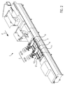
- Fig. 2 shows a packaging machine 1 with a labeling device 2 according to the invention, which comprises two transverse web labelers 4. Both transverse web labelers 4 are on a common guide system 10 is arranged.
- the common guide system 10 has two guides 11, on which the transverse web labelers 4 can be moved in and against the production direction P, respectively.
- Each transverse web labeler 4 is identified by means of an in FIG. 3 shown drive 12, preferably a servo or stepper motor, along the guides 11, for example via a toothed belt drive, movable.
- the drive 12 may also be provided as a linear direct drive or be a three-phase asynchronous or DC motor.
- Each cross-web labeler 4 has an in FIG. 3 closer illustrated measuring system 13 on.
- the distance A in FIG. 2 and 3 is the distance between the two cross-web labelers 4 to each other.
- the distance A is measured as a clear width between the two cross-web labelers 4 in the production direction P of the thermoforming packaging machine 1, for example between the two label rolls
- Fig. 3 shows in a plan view a schematic representation of the thermoforming packaging machine 1 with the labeling device 2.
- the two cross-web labelers 4 are along the guides 11 of the common guide system 10 movable.
- a movement controller 21 controls the movement for each individual cross-web labeler 4.
- the cross-web labelers 4 can be moved synchronously or independently of one another.
- the movement control 21 controls the respective drive 12 via a power supply 22 assigned to the respective drive 12, which is concretely embodied here as upstream control electronics 22.
- the drive 12 is a stepper motor and the control electronics 22 are a stepper motor controller.
- a servo motor and a power supply / control electronics 22 a servo drive conceivable.
- Each cross-web labeller 4 has a position measuring system 13 which is connected to a safety controller 14 via inputs 15 in order to notify the safety controller 14 of the position of the respective cross-web labeller 4 along the guide system 10.
- the displacement measuring system 13 may be an absolute measuring system, for example an absolute rotary encoder. If the position measuring system 13 is an incremental rotary encoder, a reference sensor 20 is provided in each case in order to refer to the cross-web labelers 4 each time the thermoforming packaging machine 1 is switched on. In this case, the reference sensor 20 corresponds to a fixed value to which the position of the cross-web labeler 4 in the safety controller 14 is set.
- the reference sensors 20 are connected to the safety controller 14.
- the safety controller 14 is an external safety controller since it is not part of the motion controller 21 or a controller 29 of the thermoforming packaging machine 1.
- the safety controller 14 has a processor 16 which contains a program which continuously evaluates the signals or the information about the position of the cross-web labelers 4 by means of the distance measuring systems 13 and calculates the distance A from them.
- the program compares the distance A with a fixed value provided in the program for the safety distance of eg 500 mm. If the program or the processor 16 determines that the current distance A of the cross-web labellers 4 is below the predetermined safety distance, the processor 16 switches relay outputs 17 to open switch contacts 18 to supply lines 19 leading from the power supplies 22 to the drives 12 and thus to interrupt the power supply of the drives 12.
- FIG. 3 is the right switch contact 18 in an open, the power supply 22 separated from the associated drive 12 position shown.
- the left switch contact 18 is shown in a closed position.
- the guide system 10 represents the common working area C, along which both transverse web labelers 4 can move.
- the safety controller 14 may include multiple modes. After the above-described safe distance mode, another mode may be provided for a synchronous operation of two cross web labellers 4 in a common direction of travel. This mode refers to the application that two cross web labellers 4 move together and synchronously at a predeterminable distance A in or against the direction of production P in order to apply labels 30 to the film web 31. Via the controller 29 of the thermoforming packaging machine 1, the various modes are selected and also the predeterminable distance A is transmitted to the safety controller 14.
- the controllers are interconnected via a bus system 28.
- the safety controller 14 checks that there is no change in distance within a predefinable tolerance, eg +/- 1 mm.
- the current distance A calculated by means of the distance measuring systems 13 and compared with the predetermined distance.
- the drives 12 are reliably switched off via the relay outputs 17.
Landscapes
- Labeling Devices (AREA)
Description
- Die Erfindung bezieht sich auf eine Etikettiereinrichtung gemäß dem Oberbegriff des Anspruchs 1 bzw. auf ein Verfahren mit den Merkmalen des Anspruchs 5.
- Aus der
DE 102 28 243 A1 ist ein typischer Querbahnetikettierer für eine Verpackungsmaschine bekannt. Bezüglich der Einzelheiten in der Konstruktion eines Querbahnetikettierers wird deshalb auf dieDE 102 28 243 A1 Bezug genommen. Generell zeichnen sich Querbahnetikettierer dadurch aus, dass sie Etiketten auf Verpackungen quer zur Transportrichtung dieser Verpackungen entlang einer Verpackungsmaschine aufbringen, typischerweise entlang jeweils einer Reihe von Verpackungen. - Es ist ferner aus der
DE 10 2006 047 488 A1 eine Etikettiereinrichtung gemäss dem Oberbegriff des Anspruchs 1 und ein Verfahren gemäss dem Oberbegriff des Anspruchs 5 bekannt. Diese Druckschrift offenbart dazu Tiefziehverpackungsmaschine mit einer Etikettiereinrichtung mit zwei Absetzkästen zum Anbringen von Etiketten auf die Verpackungen. Solche Etikettiereinrichtungen sind hinter einer Schutzeinhausung vorgesehen, damit bei der gleichzeitigen Bewegung der Absetzkästen Sicherheitsabstände für den Personenschutz unberücksichtigt bleiben können, da sich die Gefahrenstellen innerhalb der Schutzeinhausung befinden. Ansonsten würden notwendige Sicherheitsabstände zwischen den Etikettierern zu einem vergrößerten Platzbedarf der Tiefziehverpackungsmaschine führen. Nachteilig an solchen Schutzeinhausungen sind der hohe konstruktive und kostenintensive Aufwand und die schlechte Zugänglichkeit der Etikettiereinrichtung. - Aufgabe der vorliegenden Erfindung ist es, eine Etikettiereinrichtung für eine Tiefziehverpackungsmaschine bereitzustellen, die die oben genannten Nachteile nicht aufweist.
- Diese Aufgabe wird gelöst durch eine Etikettiereinrichtung für eine Verpackungsmaschine mit den Merkmalen des Anspruchs 1 bzw. durch ein Verfahren mit den Merkmalen des Anspruchs 5. Vorteilhafte Weiterbildungen der Erfindung sind in den Unteransprüchen angegeben.
- Die erfindungsgemäße Etikettiereinrichtung für eine Verpackungsmaschine umfasst zwei Querbahnetikettierer, wobei beide Querbahnetikettierer jeweils einen eigenen motorischen Antrieb und einen gemeinsamen Arbeitsbereich aufweisen. Die Etikettiereinrichtung zeichnet sich dadurch aus, dass jeder Querbahnetikettierer ein Wegmesssystem aufweist
und eine Sicherheitsteuerung vorgesehen ist, die wenigstens Eingänge für die Wegmesssysteme und zwei Relaisausgänge zum Trennen einer Energieversorgung der Antriebe, wenn der Abstand zwischen den zwei Querbahnetikettierern einen vorgegebenen Sicherheitsabstand unterschreitet, umfasst. Die Sicherheitssteuerung ist somit in der Lage, auf direktem Weg die Information über die Lage jedes Querbahnetikettierers entlang des gemeinsamen Arbeitsbereiches bzw. eines gemeinsam genutzten Führungssystems zu erhalten. Mittels der Relaisausgänge können die Antriebe der Querbahnetikettierer direkt und sicher von deren Energieversorgung getrennt werden und einen Stillstand der Querbahnetikettierer herbeiführen, um Unfällen oder Verletzungen beim Bedienpersonal vorzubeugen. Dabei sind die Relaisausgänge mit Schaltschützen verbunden, um die über die Schaltschütze laufende Energieversorgung der Antriebe zu trennen. - Dabei umfasst die Sicherheitssteuerung vorzugsweise einen Prozessor mit einem Programm. Die Sicherheitssteuerung berechnet anhand der von den Wegmesssystem erhaltenen Information, nämlich dem Zählerwert, den Abstand der zwei Querbahnetikettierer zueinander. Als "Abstand der zwei Querbahnetikettierer" wird dabei im Sinne der Erfindung der in einer Produktionsrichtung einer zugeordneten Verpackungsmaschine gemessene, lichte Abstand zwischen den zwei Querbahnetikettierern verstanden, beispielsweise gemessen zwischen den Etikettenspendern oder den Etikettenrollen der beiden Querbahnetikettierern Als Wegmesssystem kann ein lineares Wegmesssystem entlang des Führungssystems des Etikettierers oder ein Drehgeber auf der Antriebsachse eines Schritt- oder Servomotors der Antriebe eingesetzt werden.
- Das Programm bzw. die Software im Prozessor der Sicherheitssteuerung ist vorzugsweise durch eine Steuerung der Tiefziehverpackungsmaschine oder eine Steuerung der Querbahnetikettierer selbst nicht veränderbar. Das Programm bzw. die Berechnungssoftware ist sozusagen fest "gebrannt", um nach vorgeschriebenen Tests als "sicher" bewertet zu werden. Eine solche Sicherheitssteuerung kann der Sicherheitskategorie 4 nach der europäischen Norm EN 954-1 in Bezug auf das Abschaltverhalten der Antriebe entsprechen. Dabei ist es von Vorteil, mittels absoluter linearer oder rotativer Wegmesssysteme sicher die Lage der Querbahnetikettierer zu ermitteln und daraus immer den aktuellen Abstand der Querbahnetikettierer zueinander zu ermitteln. Alternativ können auch inkrementale Wegmesssysteme eingesetzt werden, die jedes Mal beim Einschalten der Tiefziehverpackungsmaschine an einer Referenzierposition mittels eines Referenzsensors referenziert werden.
- Bevorzugt ist die Sicherheitssteuerung dazu konfiguriert, die Relaisausgänge derart zu schalten, dass die Antriebe mittels Schaltkontakten, vorzugsweise Schaltschützen, von der Energieversorgung getrennt werden, wenn der berechnete Abstand einen im Programm der Sicherheitssteuerung unveränderbar festgelegten Wert für einen Sicherheitsabstand zwischen den Querbahnetikettierern unterschreitet.
- Der vorgegebene Sicherheitsabstand ist bevorzugt mindestens etwa 500 mm, um ein Quetschen oder Stoßen eines Bedieners, der sich zwischen den zwei Etikettierern befindet, durch die Etikettierer sicher zu verhindern.
- Bevorzugt ist das Wegmesssystem ein Absolutmesssystem, beispielsweise ein absoluter Drehgeber am Antrieb des Etikettierers zum Verfahren entlang einer Produktionsrichtung, sodass gegenüber einem inkrementalen Wegmesssystem ein Referenziervorgang beim Einschalten der Tiefziehverpackungsmaschine entfallen kann. Alternativ kann auch jeweils ein absolutes Linearmesssystem vorgesehen sein, das direkt die Position des jeweiligen Etikettierers entlang des gemeinsamen Arbeitsbereiches an die Sicherheitssteuerung übermittelt.
- In einer besonders vorteilhaften Ausführung ist eine Tiefziehverpackungsmaschine mit einer solchen Etikettiereinrichtung ausgestattet.
- Ein erfindungsgemäßes Verfahren zum Betrieb einer Etikettiereinrichtung auf einer Tiefziehverpackungsmaschine, die zwei Querbahnetikettierer umfasst, die jeweils einen eigenen motorischen Antrieb und einen gemeinsamen Arbeitsbereich aufweisen, zeichnet sich dadurch aus, dass eine Sicherheitssteuerung den Abstand zwischen den zwei Querbahnetikettierern ermittelt und die Antriebe der Querbahnettikettierer von einer Energieversorgung trennt, wenn der ermittelte Abstand einen vorgegebenen Sicherheitsabstand unterschreitet.
- Vorzugsweise ermittelt die Sicherheitssteuerung den Abstand der Querbahnetikettierer zueinander mittels jeweils eines Wegmesssystems des jeweiligen Antriebs.
- Bevorzugt ist das Wegmesssystem ein Absolutmesssystem, denn ein Absolutmesssystem weist den Vorteil auf, dass es lediglich beim Aufbau der Etikettiereinrichtung einmalig referenziert werden muss, aber dann zukünftig nicht mehr nach Aus-/Einschalten der Etikettiereinrichtung bzw. der Tiefziehverpackungsmaschine eine Referenzfahrt ausführen muss.
- In einer besonders vorteilhaften Ausführung ist der in der Sicherheitssteuerung hinterlegte Wert des Sicherheitsabstands unveränderbar.
- Im Folgenden wird ein vorteilhaftes Ausführungsbeispiel der Erfindung anhand von Zeichnungen näher erläutert. Im Einzelnen zeigen:
- Fig. 1
- eine Tiefziehverpackungsmaschine mit zwei Querbahnetikettierern nach dem Stand der Technik,
- Fig. 2
- eine Tiefziehverpackungsmaschine mit einer erfindungsgemäßen Etikettiereinrichtung und
- Fig. 3
- ein Schaubild der Etikettiereinrichtung mit einer Sicherheitssteuerung.
- Gleiche Komponenten sind in den Figuren durchgängig mit gleichen Bezugszeichen versehen.
-
Fig. 1 zeigt eine Tiefziehverpackungsmaschine 1 mit einer Etikettiereinrichtung 2, die in einer Produktionsrichtung P der Tiefziehverpackungsmaschine 1 stromabwärts einer Siegelstation 3 vorgesehen ist. Die Etikettiereinrichtung 2 umfasst zwei in der Produktionsrichtung P der Tiefziehverpackungsmaschine 1 hintereinander angeordnete Querbahnetikettierer 4, die jeweils ein eigenes Führungssystem 5 aufweisen. Jeder Querbahnetikettierer 4 weist einen eigenen Arbeitsbereich B auf, der über die Länge von Führungen 6 des Führungssystems 5 definiert und begrenzt wird. Beide Querbahnetikettierer 4 können sich zeitgleich entlang ihres Führungssystems 5 in und gegen die Produktionsrichtung P bewegen (siehe Doppelpfeile). Damit eine nicht dargestellte Bedienperson, die sich zwischen Etikettenspendern 7 oder Etikettenrollen 8 der Querbahnetikettierer 4 aufhält, beispielsweise zum Wechseln der Etikettenrolle 8, durch die Bewegung eines der Querbahnetikettierer 4 nicht verletzt wird, ist zwischen den zwei Querbahnetikettierern 4 ein vergleichsweise großer Sicherheitsabstand A vorgesehen. Die Querbahnetikettierer 4 bringen Etiketten 30 auf eine Folienbahn 31 auf. -
Fig. 2 zeigt eine Verpackungsmaschine 1 mit einer erfindungsgemäßen Etikettiereinrichtung 2, die zwei Querbahnetikettierer 4 umfasst. Beide Querbahnetikettierer 4 sind auf einem gemeinsamen Führungssystem 10 angeordnet. Das gemeinsame Führungssystem 10 weist zwei Führungen 11 auf, auf denen die Querbahnetikettierer 4 jeweils in und entgegen der Produktionsrichtung P verfahrbar sind. Jeder Querbahnetikettierer 4 ist mittels eines inFigur 3 dargestellten Antriebs 12, vorzugsweise eines Servo- oder Schrittmotors, entlang der Führungen 11, beispielsweise über einen Zahnriemenantrieb, verfahrbar. Der Antrieb 12 kann auch als linearer Direktantrieb vorgesehen sein oder ein Drehstromasynchronmotor oder DC-Motor sein. Jeder Querbahnetikettierer 4 weist ein inFigur 3 näher dargestelltes Wegmesssystem 13 auf. Der Abstand A inFigur 2 und3 ist der Abstand zwischen den zwei Querbahnetikettierern 4 zueinander. Gemessen wird der Abstand A als lichte Weite zwischen den beiden Querbahnetikettierern 4 in Produktionsrichtung P der Tiefziehverpackungsmaschine 1, beispielsweise zwischen den beiden Etikettenrollen 8. -
Fig. 3 zeigt in einer Draufsicht eine schematische Darstellung der Tiefziehverpackungsmaschine 1 mit der Etikettiereinrichtung 2. Die zwei Querbahnetikettierer 4 sind entlang der Führungen 11 des gemeinsamen Führungssystems 10 verfahrbar. Eine Bewegungssteuerung 21 steuert die Bewegung für jeden einzelnen Querbahnetikettierer 4. Dabei können die Querbahnetikettierer 4 synchron oder unabhängig voneinander verfahren werden. Die Bewegungssteuerung 21 steuert den jeweiligen Antrieb 12 über eine dem jeweiligen Antrieb 12 zugeordnete Energieversorgung 22, die hier konkret ausgebildet ist als eine vorgeschaltete Regelelektronik 22. In der gezeigten Variante ist der Antrieb 12 ein Schrittmotor und die Regelelektronik 22 ein Schrittmotorregler. Ebenso ist als Antrieb 12 ein Servomotor und als Energieversorgung/Regelelektronik 22 ein Servoregler denkbar. - Jeder Querbahnetikettierer 4 weist ein Wegmesssystem 13 auf, das mit einer Sicherheitssteuerung 14 über Eingänge 15 verbunden ist, um der Sicherheitssteuerung 14 die Position des jeweiligen Querbahnetikettierers 4 entlang des Führungssystems 10 mitzuteilen. Das Wegmesssystem 13 kann ein Absolutmesssystem, beispielsweise ein Absolutdrehgeber, sein. Ist das Wegmesssystem 13 ein inkrementaler Drehgeber, so ist jeweils ein Referenzsensor 20 vorgesehen, um nach jedem Einschalten der Tiefziehverpackungsmaschine 1 die Querbahnetikettierer 4 zu referenzieren. Dabei entspricht der Referenzsensor 20 einem festen Wert, auf den die Position des Querbahnetikettierers 4 in der Sicherheitssteuerung 14 gesetzt wird. Die Referenzsensoren 20 sind mit der Sicherheitssteuerung 14 verbunden.
- Die Sicherheitssteuerung 14 ist eine externe Sicherheitssteuerung, da sie kein Teil der Bewegungssteuerung 21 oder einer Steuerung 29 der Tiefziehverpackungsmaschine 1 ist. Die Sicherheitssteuerung 14 weist einen Prozessor 16 auf, der ein Programm beinhaltet, das die Signale bzw. die Information über die Position der Querbahnetikettierer 4 mittels der Wegmesssysteme 13 laufend auswertet und daraus den Abstand A berechnet. Das Programm vergleicht dabei den Abstand A mit einem in dem Programm unveränderlich vorgesehenen Wert für den Sicherheitsabstand von z.B. 500 mm. Ermittelt das Programm bzw. der Prozessor 16, dass der aktuelle Abstand A der Querbahnetikettierer 4 zueinander den vorgegebenen Sicherheitsabstand unterschreitet, schaltet der Prozessor 16 Relaisausgänge 17, um Schaltkontakte 18 zu öffnen, um von den Energieversorgungen 22 zu den Antrieben 12 führende Verbindungsleitungen 19 und damit die Energieversorgung der Antriebe 12 zu unterbrechen. Dies gewährleistet ein sicheres Anhalten eines oder beider Querbahnetikettierer 4. In
Figur 3 ist der rechte Schaltkontakt 18 in einer geöffneten, die Energieversorgung 22 von dem zugeordneten Antrieb 12 trennenden Stellung gezeigt. Der linke Schaltkontakt 18 ist in einer geschlossenen Stellung gezeigt. Das Führungssystem 10 stellt den gemeinsamen Arbeitsbereich C dar, entlang dessen sich beide Querbahnetikettierer 4 bewegen können. - Denkbar wäre es auch, beide Schaltkontakte über einen einzigen, gemeinsamen Relaisausgang 17 an der Sicherheitssteuerung 14 anzusteuern.
- Die Sicherheitssteuerung 14 kann mehrere Modi umfassen. Nach dem zuvor beschriebenen Modus für die Prüfung auf den Sicherheitsabstand kann ein weiterer Modus für ein synchrones Verfahren von zwei Querbahnetikettierern 4 in eine gemeinsame Bewegungsrichtung vorgesehen sein. Dieser Modus bezieht sich auf die Anwendung, dass zwei Querbahnetikettierer 4 gemeinsam und synchron in einem vorgebbaren Abstand A in oder entgegen der Produktionsrichtung P verfahren, um Etiketten 30 auf die Folienbahn 31 aufzubringen. Über die Steuerung 29 der Tiefziehverpackungsmaschine 1 werden die verschiedenen Modi ausgewählt und auch der vorgebbare Abstand A an die Sicherheitssteuerung 14 übermittelt.
- Vorzugsweise sind die Steuerungen untereinander über ein Bus-System 28 miteinander verbunden. Während des synchronen Verfahrens der zwei Querbahnetikettierer 4 überprüft die Sicherheitssteuerung 14, dass es zu keiner Abstandsveränderung innerhalb einer vorgebbaren Toleranz, z.B. +/- 1 mm, kommt. Hierbei wird der aktuelle Abstand A mittels der Wegmesssysteme 13 berechnet und mit dem vorgebbaren Abstand verglichen. Im Fehlerfall werden die Antriebe 12 über die Relaisausgänge 17 sicher abgeschaltet.
Claims (8)
- Etikettiereinrichtung (2), umfassend zwei Querbahnetikettierer (4), wobei jeder Querbahnetikettierer (4) einen eigenen motorischen Antrieb (12) aufweist, wobei jedem Antrieb (12) eine eigene Energieversorgung (22) für den jeweiligen Antrieb (12) zugeordnet ist, wobei die Energieversorgung (22) über eine Verbindungsleitung (19) mit dem zugeordneten Antrieb (12) verbunden ist, und wobei beide Querbahnetikettierer (4) einen gemeinsamen Arbeitsbereich (C) aufweisen, dadurch gekennzeichnet, dass jeder Querbahnetikettierer (4) ein Wegmesssystem (13) aufweist, und dass eine Sicherheitssteuerung (14) vorgesehen ist, die wenigstens Eingänge (15) für die Wegmesssysteme (13) und ferner einen oder zwei Relaisausgänge (17) zum Trennen der Verbindungsleitungen (19) beider Antriebe (12) der Querbahnetikettierer (4), wenn der Abstand zwischen den zwei Querbahnetikettierern einen vorgegebenen Sicherheitsabstand unterschreitet, umfasst.
- Etikettiereinrichtung nach Anspruch 1, dadurch gekennzeichnet, dass die Sicherheitssteuerung (14) einen Prozessor (16) mit einem Programm umfasst, und konfiguriert ist, um anhand der Information der Wegmesssysteme (13) den Abstand (A) der zwei Querbahnetikettierer (4) zueinander zu berechnen.
- Etikettiereinrichtung nach einem der vorangehenden Ansprüche, dadurch gekennzeichnet, dass das Wegmesssystem (13) ein Absolutmesssystem ist.
- Tiefziehverpackungsmaschine mit einer Etikettiereinrichtung (2) nach einem der vorangehenden Ansprüche.
- Verfahren zum Betrieb einer Etikettiereinrichtung (2) nach einem der Ansprüche 1-3, auf einer Tiefziehverpackungsmaschine (1), umfassend zwei Querbahnetikettierer (4), die jeweils einen eigenen motorischen Antrieb (12) und einen gemeinsamen Arbeitsbereich (C) aufweisen, dadurch gekennzeichnet, dass eine Sicherheitssteuerung (14) den Abstand (A) zwischen den zwei Querbahnetikettierern (4) ermittelt und die Antriebe (12) der Querbahnettikettierer (4) von einer Energieversorgung (22) trennt, wenn der Abstand (A) einen vorgegebenen Sicherheitsabstand unterschreitet.
- Verfahren nach Anspruch 5, dadurch gekennzeichnet, dass die Sicherheitssteuerung (14) den Abstand (A) mittels mehrerer, jeweils einem Antrieb (12) zugeordneter Wegmesssysteme (13) ermittelt.
- Verfahren nach Anspruch 6, dadurch gekennzeichnet, dass jedes Wegmesssystem (13) ein Absolutmesssystem ist.
- Verfahren nach einem der Ansprüche 5 bis 7, dadurch gekennzeichnet, dass der in der Sicherheitssteuerung (14) hinterlegte Wert des Sicherheitsabstands unveränderbar ist.
Priority Applications (4)
| Application Number | Priority Date | Filing Date | Title |
|---|---|---|---|
| ES14160019.7T ES2592214T3 (es) | 2014-03-14 | 2014-03-14 | Equipo de etiquetado con monitorización de distancia electrónica |
| DK14160019.7T DK2918503T3 (en) | 2014-03-14 | 2014-03-14 | Labeling device with electronic distance monitoring |
| EP14160019.7A EP2918503B1 (de) | 2014-03-14 | 2014-03-14 | Etikettiereinrichtung mit elektronischer Abstandsüberwachung |
| US14/656,366 US9463892B2 (en) | 2014-03-14 | 2015-03-12 | Labeling device with electronic distance monitoring |
Applications Claiming Priority (1)
| Application Number | Priority Date | Filing Date | Title |
|---|---|---|---|
| EP14160019.7A EP2918503B1 (de) | 2014-03-14 | 2014-03-14 | Etikettiereinrichtung mit elektronischer Abstandsüberwachung |
Publications (2)
| Publication Number | Publication Date |
|---|---|
| EP2918503A1 EP2918503A1 (de) | 2015-09-16 |
| EP2918503B1 true EP2918503B1 (de) | 2016-08-31 |
Family
ID=50277098
Family Applications (1)
| Application Number | Title | Priority Date | Filing Date |
|---|---|---|---|
| EP14160019.7A Active EP2918503B1 (de) | 2014-03-14 | 2014-03-14 | Etikettiereinrichtung mit elektronischer Abstandsüberwachung |
Country Status (4)
| Country | Link |
|---|---|
| US (1) | US9463892B2 (de) |
| EP (1) | EP2918503B1 (de) |
| DK (1) | DK2918503T3 (de) |
| ES (1) | ES2592214T3 (de) |
Cited By (3)
| Publication number | Priority date | Publication date | Assignee | Title |
|---|---|---|---|---|
| CN109018582A (zh) * | 2018-10-26 | 2018-12-18 | 海盐创美印业有限公司 | 一种包装盒贴标装置 |
| CN109178528A (zh) * | 2018-08-18 | 2019-01-11 | 合肥职业技术学院 | 一种纸箱双面贴标的流水线装置 |
| CN109625846A (zh) * | 2018-11-19 | 2019-04-16 | 张少龙 | 箱包的输送装置 |
Families Citing this family (4)
| Publication number | Priority date | Publication date | Assignee | Title |
|---|---|---|---|---|
| JP7172397B2 (ja) * | 2018-10-02 | 2022-11-16 | オムロン株式会社 | 制御システム、サポート装置およびプログラム |
| CN210162397U (zh) * | 2019-01-28 | 2020-03-20 | 广东比实希科技有限公司 | 一种带有编码器的标签剥离机 |
| CN110254880B (zh) * | 2019-06-19 | 2021-10-26 | 苏州精濑光电有限公司 | 一种贴标装置及产线 |
| CN111746891B (zh) * | 2020-07-23 | 2024-04-05 | 广东紫泉标签有限公司 | 一种罐体标签自动粘贴装置 |
Family Cites Families (4)
| Publication number | Priority date | Publication date | Assignee | Title |
|---|---|---|---|---|
| DE10228243B4 (de) | 2002-06-25 | 2008-08-21 | Mr-Etikettiertechnik Gmbh & Co. Kg | Querbahn-Etikettierverfahren und -vorrichtung |
| DE102006047488B4 (de) * | 2006-10-05 | 2017-12-21 | Cfs Germany Gmbh | Verpackungsmaschine mit einer Etikettierungsvorrichtung |
| DE102008007890B4 (de) * | 2008-02-07 | 2022-10-13 | Multivac Marking & Inspection Gmbh & Co. Kg | Querbahn-Etikettierverfahren, sowie Etikettierer |
| EP2666728B1 (de) * | 2012-05-22 | 2016-12-07 | MULTIVAC Marking & Inspection GmbH & Co. KG | Etikettierer und Verfahren zum Etikettieren |
-
2014
- 2014-03-14 DK DK14160019.7T patent/DK2918503T3/en active
- 2014-03-14 EP EP14160019.7A patent/EP2918503B1/de active Active
- 2014-03-14 ES ES14160019.7T patent/ES2592214T3/es active Active
-
2015
- 2015-03-12 US US14/656,366 patent/US9463892B2/en active Active
Cited By (3)
| Publication number | Priority date | Publication date | Assignee | Title |
|---|---|---|---|---|
| CN109178528A (zh) * | 2018-08-18 | 2019-01-11 | 合肥职业技术学院 | 一种纸箱双面贴标的流水线装置 |
| CN109018582A (zh) * | 2018-10-26 | 2018-12-18 | 海盐创美印业有限公司 | 一种包装盒贴标装置 |
| CN109625846A (zh) * | 2018-11-19 | 2019-04-16 | 张少龙 | 箱包的输送装置 |
Also Published As
| Publication number | Publication date |
|---|---|
| US9463892B2 (en) | 2016-10-11 |
| US20150259089A1 (en) | 2015-09-17 |
| ES2592214T3 (es) | 2016-11-28 |
| EP2918503A1 (de) | 2015-09-16 |
| DK2918503T3 (en) | 2016-11-28 |
Similar Documents
| Publication | Publication Date | Title |
|---|---|---|
| EP2918503A1 (de) | Etikettiereinrichtung mit elektronischer Abstandsüberwachung | |
| EP3202612B1 (de) | Verfahren zum betreiben einer fördereinrichtung in form eines langstatorlinearmotors | |
| EP2740679B1 (de) | Tiefziehverpackungsmaschine mit taktgenauer Positionierung einer Siegelstation und entsprechendes Verfahren | |
| DE10334736A1 (de) | Linearmotor mit Fortbewegungsregelung | |
| WO2015036197A1 (de) | Vorrichtung und verfahren zum transport von behältern in einer behälterbehandlungsanlage | |
| EP3599127A1 (de) | Verfahren zum betreiben eines langstatorlinearmotors mit transporteinheiten und kollisionsüberwachung | |
| EP3802384B1 (de) | Verfahren zum steuern einer transporteinheit einer transporteinrichtung in form eines langstatorlinearmotors | |
| DE102007045143A1 (de) | Bearbeitungs- beziehungsweise Fertigungsanlage | |
| EP3831639A1 (de) | Sicherheitsfunktion für ein transportsystem | |
| EP3006359B1 (de) | Etikettieren von Falzprodukten | |
| EP2110346B1 (de) | Anordnung und Verfahren zum Transport und zur Synchronverteilung von Behältnissen | |
| EP3663034A1 (de) | Verfahren zum anziehen von schraubverbindungen | |
| EP2873623B1 (de) | Tiefziehverpackungsmaschine mit verstellbarer Kettenführung | |
| EP3521185B1 (de) | Verfahren zum steuern des vorschubs einer folienbahn in einer verpackungsmaschine | |
| EP3495225B1 (de) | Fahrzeug, insbesondere schienenfahrzeug, mit antriebssteuereinrichtung | |
| EP1455976B2 (de) | Maulweitenregelung an segmenten für stranggie anlagen | |
| EP3191357B1 (de) | Förderanlage mit sicherheitsfunktion | |
| EP4046918A1 (de) | Eingreifsicherung für eine arbeitsstation einer verpackungsmaschine | |
| EP3464011B1 (de) | Schienenfahrzeug für ein schienentransportsystem und schienentransportsystem | |
| EP3057895A1 (de) | Transportvorrichtung für bahn- und/oder band-förmiges material | |
| DE4412493C2 (de) | Staugutförderer für Stückgut aller Art | |
| DE102009008132B4 (de) | Torsteuerung zur Steuerung eines elektromotorisch angetriebenen Tores | |
| DE102007017285A1 (de) | Verfahren und Vorrichtung zum Überwachen von Drehstrommaschinen | |
| CH694255A5 (de) | Widerstandsbeheizte Trennvorrichtung für textile Bahnen. | |
| DE102016203814B4 (de) | Vorrichtung zum Transport von Packmittel, insbesondere von Flaschen oder Bechern |
Legal Events
| Date | Code | Title | Description |
|---|---|---|---|
| PUAI | Public reference made under article 153(3) epc to a published international application that has entered the european phase |
Free format text: ORIGINAL CODE: 0009012 |
|
| AK | Designated contracting states |
Kind code of ref document: A1 Designated state(s): AL AT BE BG CH CY CZ DE DK EE ES FI FR GB GR HR HU IE IS IT LI LT LU LV MC MK MT NL NO PL PT RO RS SE SI SK SM TR |
|
| AX | Request for extension of the european patent |
Extension state: BA ME |
|
| 17P | Request for examination filed |
Effective date: 20151111 |
|
| RBV | Designated contracting states (corrected) |
Designated state(s): AL AT BE BG CH CY CZ DE DK EE ES FI FR GB GR HR HU IE IS IT LI LT LU LV MC MK MT NL NO PL PT RO RS SE SI SK SM TR |
|
| GRAP | Despatch of communication of intention to grant a patent |
Free format text: ORIGINAL CODE: EPIDOSNIGR1 |
|
| GRAP | Despatch of communication of intention to grant a patent |
Free format text: ORIGINAL CODE: EPIDOSNIGR1 |
|
| INTG | Intention to grant announced |
Effective date: 20160301 |
|
| INTG | Intention to grant announced |
Effective date: 20160315 |
|
| GRAS | Grant fee paid |
Free format text: ORIGINAL CODE: EPIDOSNIGR3 |
|
| GRAA | (expected) grant |
Free format text: ORIGINAL CODE: 0009210 |
|
| AK | Designated contracting states |
Kind code of ref document: B1 Designated state(s): AL AT BE BG CH CY CZ DE DK EE ES FI FR GB GR HR HU IE IS IT LI LT LU LV MC MK MT NL NO PL PT RO RS SE SI SK SM TR |
|
| REG | Reference to a national code |
Ref country code: CH Ref legal event code: EP Ref country code: CH Ref legal event code: NV Representative=s name: BOVARD AG, CH Ref country code: GB Ref legal event code: FG4D Free format text: NOT ENGLISH |
|
| REG | Reference to a national code |
Ref country code: IE Ref legal event code: FG4D Free format text: LANGUAGE OF EP DOCUMENT: GERMAN |
|
| REG | Reference to a national code |
Ref country code: DE Ref legal event code: R096 Ref document number: 502014001333 Country of ref document: DE |
|
| REG | Reference to a national code |
Ref country code: AT Ref legal event code: REF Ref document number: 824747 Country of ref document: AT Kind code of ref document: T Effective date: 20161015 |
|
| REG | Reference to a national code |
Ref country code: ES Ref legal event code: FG2A Ref document number: 2592214 Country of ref document: ES Kind code of ref document: T3 Effective date: 20161128 Ref country code: DK Ref legal event code: T3 Effective date: 20161121 |
|
| REG | Reference to a national code |
Ref country code: NL Ref legal event code: FP |
|
| REG | Reference to a national code |
Ref country code: SE Ref legal event code: TRGR |
|
| REG | Reference to a national code |
Ref country code: LT Ref legal event code: MG4D |
|
| PG25 | Lapsed in a contracting state [announced via postgrant information from national office to epo] |
Ref country code: HR Free format text: LAPSE BECAUSE OF FAILURE TO SUBMIT A TRANSLATION OF THE DESCRIPTION OR TO PAY THE FEE WITHIN THE PRESCRIBED TIME-LIMIT Effective date: 20160831 Ref country code: LT Free format text: LAPSE BECAUSE OF FAILURE TO SUBMIT A TRANSLATION OF THE DESCRIPTION OR TO PAY THE FEE WITHIN THE PRESCRIBED TIME-LIMIT Effective date: 20160831 Ref country code: NO Free format text: LAPSE BECAUSE OF FAILURE TO SUBMIT A TRANSLATION OF THE DESCRIPTION OR TO PAY THE FEE WITHIN THE PRESCRIBED TIME-LIMIT Effective date: 20161130 Ref country code: RS Free format text: LAPSE BECAUSE OF FAILURE TO SUBMIT A TRANSLATION OF THE DESCRIPTION OR TO PAY THE FEE WITHIN THE PRESCRIBED TIME-LIMIT Effective date: 20160831 Ref country code: FI Free format text: LAPSE BECAUSE OF FAILURE TO SUBMIT A TRANSLATION OF THE DESCRIPTION OR TO PAY THE FEE WITHIN THE PRESCRIBED TIME-LIMIT Effective date: 20160831 |
|
| PG25 | Lapsed in a contracting state [announced via postgrant information from national office to epo] |
Ref country code: LV Free format text: LAPSE BECAUSE OF FAILURE TO SUBMIT A TRANSLATION OF THE DESCRIPTION OR TO PAY THE FEE WITHIN THE PRESCRIBED TIME-LIMIT Effective date: 20160831 Ref country code: GR Free format text: LAPSE BECAUSE OF FAILURE TO SUBMIT A TRANSLATION OF THE DESCRIPTION OR TO PAY THE FEE WITHIN THE PRESCRIBED TIME-LIMIT Effective date: 20161201 |
|
| REG | Reference to a national code |
Ref country code: FR Ref legal event code: PLFP Year of fee payment: 4 |
|
| PG25 | Lapsed in a contracting state [announced via postgrant information from national office to epo] |
Ref country code: EE Free format text: LAPSE BECAUSE OF FAILURE TO SUBMIT A TRANSLATION OF THE DESCRIPTION OR TO PAY THE FEE WITHIN THE PRESCRIBED TIME-LIMIT Effective date: 20160831 Ref country code: RO Free format text: LAPSE BECAUSE OF FAILURE TO SUBMIT A TRANSLATION OF THE DESCRIPTION OR TO PAY THE FEE WITHIN THE PRESCRIBED TIME-LIMIT Effective date: 20160831 |
|
| PG25 | Lapsed in a contracting state [announced via postgrant information from national office to epo] |
Ref country code: BG Free format text: LAPSE BECAUSE OF FAILURE TO SUBMIT A TRANSLATION OF THE DESCRIPTION OR TO PAY THE FEE WITHIN THE PRESCRIBED TIME-LIMIT Effective date: 20161130 Ref country code: SM Free format text: LAPSE BECAUSE OF FAILURE TO SUBMIT A TRANSLATION OF THE DESCRIPTION OR TO PAY THE FEE WITHIN THE PRESCRIBED TIME-LIMIT Effective date: 20160831 Ref country code: SK Free format text: LAPSE BECAUSE OF FAILURE TO SUBMIT A TRANSLATION OF THE DESCRIPTION OR TO PAY THE FEE WITHIN THE PRESCRIBED TIME-LIMIT Effective date: 20160831 Ref country code: PT Free format text: LAPSE BECAUSE OF FAILURE TO SUBMIT A TRANSLATION OF THE DESCRIPTION OR TO PAY THE FEE WITHIN THE PRESCRIBED TIME-LIMIT Effective date: 20170102 Ref country code: PL Free format text: LAPSE BECAUSE OF FAILURE TO SUBMIT A TRANSLATION OF THE DESCRIPTION OR TO PAY THE FEE WITHIN THE PRESCRIBED TIME-LIMIT Effective date: 20160831 Ref country code: CZ Free format text: LAPSE BECAUSE OF FAILURE TO SUBMIT A TRANSLATION OF THE DESCRIPTION OR TO PAY THE FEE WITHIN THE PRESCRIBED TIME-LIMIT Effective date: 20160831 |
|
| REG | Reference to a national code |
Ref country code: DE Ref legal event code: R097 Ref document number: 502014001333 Country of ref document: DE |
|
| PLBE | No opposition filed within time limit |
Free format text: ORIGINAL CODE: 0009261 |
|
| STAA | Information on the status of an ep patent application or granted ep patent |
Free format text: STATUS: NO OPPOSITION FILED WITHIN TIME LIMIT |
|
| 26N | No opposition filed |
Effective date: 20170601 |
|
| PG25 | Lapsed in a contracting state [announced via postgrant information from national office to epo] |
Ref country code: SI Free format text: LAPSE BECAUSE OF FAILURE TO SUBMIT A TRANSLATION OF THE DESCRIPTION OR TO PAY THE FEE WITHIN THE PRESCRIBED TIME-LIMIT Effective date: 20160831 |
|
| PG25 | Lapsed in a contracting state [announced via postgrant information from national office to epo] |
Ref country code: MC Free format text: LAPSE BECAUSE OF FAILURE TO SUBMIT A TRANSLATION OF THE DESCRIPTION OR TO PAY THE FEE WITHIN THE PRESCRIBED TIME-LIMIT Effective date: 20160831 |
|
| REG | Reference to a national code |
Ref country code: IE Ref legal event code: MM4A |
|
| PG25 | Lapsed in a contracting state [announced via postgrant information from national office to epo] |
Ref country code: LU Free format text: LAPSE BECAUSE OF NON-PAYMENT OF DUE FEES Effective date: 20170314 |
|
| PG25 | Lapsed in a contracting state [announced via postgrant information from national office to epo] |
Ref country code: IE Free format text: LAPSE BECAUSE OF NON-PAYMENT OF DUE FEES Effective date: 20170314 |
|
| REG | Reference to a national code |
Ref country code: BE Ref legal event code: MM Effective date: 20170331 |
|
| REG | Reference to a national code |
Ref country code: FR Ref legal event code: PLFP Year of fee payment: 5 |
|
| PG25 | Lapsed in a contracting state [announced via postgrant information from national office to epo] |
Ref country code: BE Free format text: LAPSE BECAUSE OF NON-PAYMENT OF DUE FEES Effective date: 20170331 |
|
| PG25 | Lapsed in a contracting state [announced via postgrant information from national office to epo] |
Ref country code: MT Free format text: LAPSE BECAUSE OF FAILURE TO SUBMIT A TRANSLATION OF THE DESCRIPTION OR TO PAY THE FEE WITHIN THE PRESCRIBED TIME-LIMIT Effective date: 20160831 |
|
| PG25 | Lapsed in a contracting state [announced via postgrant information from national office to epo] |
Ref country code: AL Free format text: LAPSE BECAUSE OF FAILURE TO SUBMIT A TRANSLATION OF THE DESCRIPTION OR TO PAY THE FEE WITHIN THE PRESCRIBED TIME-LIMIT Effective date: 20160831 |
|
| PG25 | Lapsed in a contracting state [announced via postgrant information from national office to epo] |
Ref country code: HU Free format text: LAPSE BECAUSE OF FAILURE TO SUBMIT A TRANSLATION OF THE DESCRIPTION OR TO PAY THE FEE WITHIN THE PRESCRIBED TIME-LIMIT; INVALID AB INITIO Effective date: 20140314 |
|
| PG25 | Lapsed in a contracting state [announced via postgrant information from national office to epo] |
Ref country code: CY Free format text: LAPSE BECAUSE OF FAILURE TO SUBMIT A TRANSLATION OF THE DESCRIPTION OR TO PAY THE FEE WITHIN THE PRESCRIBED TIME-LIMIT Effective date: 20160831 |
|
| PG25 | Lapsed in a contracting state [announced via postgrant information from national office to epo] |
Ref country code: MK Free format text: LAPSE BECAUSE OF FAILURE TO SUBMIT A TRANSLATION OF THE DESCRIPTION OR TO PAY THE FEE WITHIN THE PRESCRIBED TIME-LIMIT Effective date: 20160831 |
|
| PG25 | Lapsed in a contracting state [announced via postgrant information from national office to epo] |
Ref country code: TR Free format text: LAPSE BECAUSE OF FAILURE TO SUBMIT A TRANSLATION OF THE DESCRIPTION OR TO PAY THE FEE WITHIN THE PRESCRIBED TIME-LIMIT Effective date: 20160831 |
|
| PG25 | Lapsed in a contracting state [announced via postgrant information from national office to epo] |
Ref country code: IS Free format text: LAPSE BECAUSE OF FAILURE TO SUBMIT A TRANSLATION OF THE DESCRIPTION OR TO PAY THE FEE WITHIN THE PRESCRIBED TIME-LIMIT Effective date: 20161231 |
|
| REG | Reference to a national code |
Ref country code: AT Ref legal event code: MM01 Ref document number: 824747 Country of ref document: AT Kind code of ref document: T Effective date: 20190314 |
|
| PG25 | Lapsed in a contracting state [announced via postgrant information from national office to epo] |
Ref country code: AT Free format text: LAPSE BECAUSE OF NON-PAYMENT OF DUE FEES Effective date: 20190314 |
|
| P01 | Opt-out of the competence of the unified patent court (upc) registered |
Effective date: 20230404 |
|
| PGFP | Annual fee paid to national office [announced via postgrant information from national office to epo] |
Ref country code: ES Payment date: 20250416 Year of fee payment: 12 |
|
| PGFP | Annual fee paid to national office [announced via postgrant information from national office to epo] |
Ref country code: IT Payment date: 20250331 Year of fee payment: 12 |
|
| PGFP | Annual fee paid to national office [announced via postgrant information from national office to epo] |
Ref country code: CH Payment date: 20250401 Year of fee payment: 12 |
|
| REG | Reference to a national code |
Ref country code: CH Ref legal event code: U11 Free format text: ST27 STATUS EVENT CODE: U-0-0-U10-U11 (AS PROVIDED BY THE NATIONAL OFFICE) Effective date: 20260401 |
|
| PGFP | Annual fee paid to national office [announced via postgrant information from national office to epo] |
Ref country code: SE Payment date: 20260323 Year of fee payment: 13 |
|
| PGFP | Annual fee paid to national office [announced via postgrant information from national office to epo] |
Ref country code: GB Payment date: 20260324 Year of fee payment: 13 |
|
| PGFP | Annual fee paid to national office [announced via postgrant information from national office to epo] |
Ref country code: DE Payment date: 20260320 Year of fee payment: 13 Ref country code: DK Payment date: 20260323 Year of fee payment: 13 |
|
| PGFP | Annual fee paid to national office [announced via postgrant information from national office to epo] |
Ref country code: NL Payment date: 20260323 Year of fee payment: 13 |
|
| PGFP | Annual fee paid to national office [announced via postgrant information from national office to epo] |
Ref country code: FR Payment date: 20260324 Year of fee payment: 13 |