EP2918249B1 - Supraclaviculäres kathetersystem für einen transseptalen zugang zum linken vorhof und linken ventrikel - Google Patents
Supraclaviculäres kathetersystem für einen transseptalen zugang zum linken vorhof und linken ventrikel Download PDFInfo
- Publication number
- EP2918249B1 EP2918249B1 EP15158051.1A EP15158051A EP2918249B1 EP 2918249 B1 EP2918249 B1 EP 2918249B1 EP 15158051 A EP15158051 A EP 15158051A EP 2918249 B1 EP2918249 B1 EP 2918249B1
- Authority
- EP
- European Patent Office
- Prior art keywords
- catheter
- section
- mitral valve
- positioning catheter
- curved
- Prior art date
- Legal status (The legal status is an assumption and is not a legal conclusion. Google has not performed a legal analysis and makes no representation as to the accuracy of the status listed.)
- Revoked
Links
Images


Classifications
-
- A—HUMAN NECESSITIES
- A61—MEDICAL OR VETERINARY SCIENCE; HYGIENE
- A61F—FILTERS IMPLANTABLE INTO BLOOD VESSELS; PROSTHESES; DEVICES PROVIDING PATENCY TO, OR PREVENTING COLLAPSING OF, TUBULAR STRUCTURES OF THE BODY, e.g. STENTS; ORTHOPAEDIC, NURSING OR CONTRACEPTIVE DEVICES; FOMENTATION; TREATMENT OR PROTECTION OF EYES OR EARS; BANDAGES, DRESSINGS OR ABSORBENT PADS; FIRST-AID KITS
- A61F2/00—Filters implantable into blood vessels; Prostheses, i.e. artificial substitutes or replacements for parts of the body; Appliances for connecting them with the body; Devices providing patency to, or preventing collapsing of, tubular structures of the body, e.g. stents
- A61F2/02—Prostheses implantable into the body
- A61F2/24—Heart valves ; Vascular valves, e.g. venous valves; Heart implants, e.g. passive devices for improving the function of the native valve or the heart muscle; Transmyocardial revascularisation [TMR] devices; Valves implantable in the body
- A61F2/2427—Devices for manipulating or deploying heart valves during implantation
-
- A—HUMAN NECESSITIES
- A61—MEDICAL OR VETERINARY SCIENCE; HYGIENE
- A61F—FILTERS IMPLANTABLE INTO BLOOD VESSELS; PROSTHESES; DEVICES PROVIDING PATENCY TO, OR PREVENTING COLLAPSING OF, TUBULAR STRUCTURES OF THE BODY, e.g. STENTS; ORTHOPAEDIC, NURSING OR CONTRACEPTIVE DEVICES; FOMENTATION; TREATMENT OR PROTECTION OF EYES OR EARS; BANDAGES, DRESSINGS OR ABSORBENT PADS; FIRST-AID KITS
- A61F2/00—Filters implantable into blood vessels; Prostheses, i.e. artificial substitutes or replacements for parts of the body; Appliances for connecting them with the body; Devices providing patency to, or preventing collapsing of, tubular structures of the body, e.g. stents
- A61F2/0063—Implantable repair or support meshes, e.g. hernia meshes
-
- A—HUMAN NECESSITIES
- A61—MEDICAL OR VETERINARY SCIENCE; HYGIENE
- A61B—DIAGNOSIS; SURGERY; IDENTIFICATION
- A61B17/00—Surgical instruments, devices or methods
- A61B17/00234—Surgical instruments, devices or methods for minimally invasive surgery
- A61B2017/00238—Type of minimally invasive operation
- A61B2017/00243—Type of minimally invasive operation cardiac
-
- A—HUMAN NECESSITIES
- A61—MEDICAL OR VETERINARY SCIENCE; HYGIENE
- A61B—DIAGNOSIS; SURGERY; IDENTIFICATION
- A61B17/00—Surgical instruments, devices or methods
- A61B17/0057—Implements for plugging an opening in the wall of a hollow or tubular organ, e.g. for sealing a vessel puncture or closing a cardiac septal defect
- A61B2017/00575—Implements for plugging an opening in the wall of a hollow or tubular organ, e.g. for sealing a vessel puncture or closing a cardiac septal defect for closure at remote site, e.g. closing atrial septum defects
- A61B2017/00597—Implements comprising a membrane
-
- A—HUMAN NECESSITIES
- A61—MEDICAL OR VETERINARY SCIENCE; HYGIENE
- A61B—DIAGNOSIS; SURGERY; IDENTIFICATION
- A61B17/00—Surgical instruments, devices or methods
- A61B17/0057—Implements for plugging an opening in the wall of a hollow or tubular organ, e.g. for sealing a vessel puncture or closing a cardiac septal defect
- A61B2017/00575—Implements for plugging an opening in the wall of a hollow or tubular organ, e.g. for sealing a vessel puncture or closing a cardiac septal defect for closure at remote site, e.g. closing atrial septum defects
- A61B2017/0061—Implements located only on one side of the opening
-
- A—HUMAN NECESSITIES
- A61—MEDICAL OR VETERINARY SCIENCE; HYGIENE
- A61B—DIAGNOSIS; SURGERY; IDENTIFICATION
- A61B17/00—Surgical instruments, devices or methods
- A61B17/0057—Implements for plugging an opening in the wall of a hollow or tubular organ, e.g. for sealing a vessel puncture or closing a cardiac septal defect
- A61B2017/00646—Type of implements
- A61B2017/00659—Type of implements located only on one side of the opening
-
- A—HUMAN NECESSITIES
- A61—MEDICAL OR VETERINARY SCIENCE; HYGIENE
- A61B—DIAGNOSIS; SURGERY; IDENTIFICATION
- A61B17/00—Surgical instruments, devices or methods
- A61B17/12—Surgical instruments, devices or methods for ligaturing or otherwise compressing tubular parts of the body, e.g. blood vessels or umbilical cord
- A61B17/12022—Occluding by internal devices, e.g. balloons or releasable wires
- A61B2017/1205—Introduction devices
- A61B2017/12054—Details concerning the detachment of the occluding device from the introduction device
- A61B2017/12081—Details concerning the detachment of the occluding device from the introduction device detachable by inflation
-
- A—HUMAN NECESSITIES
- A61—MEDICAL OR VETERINARY SCIENCE; HYGIENE
- A61F—FILTERS IMPLANTABLE INTO BLOOD VESSELS; PROSTHESES; DEVICES PROVIDING PATENCY TO, OR PREVENTING COLLAPSING OF, TUBULAR STRUCTURES OF THE BODY, e.g. STENTS; ORTHOPAEDIC, NURSING OR CONTRACEPTIVE DEVICES; FOMENTATION; TREATMENT OR PROTECTION OF EYES OR EARS; BANDAGES, DRESSINGS OR ABSORBENT PADS; FIRST-AID KITS
- A61F2/00—Filters implantable into blood vessels; Prostheses, i.e. artificial substitutes or replacements for parts of the body; Appliances for connecting them with the body; Devices providing patency to, or preventing collapsing of, tubular structures of the body, e.g. stents
- A61F2/02—Prostheses implantable into the body
- A61F2/24—Heart valves ; Vascular valves, e.g. venous valves; Heart implants, e.g. passive devices for improving the function of the native valve or the heart muscle; Transmyocardial revascularisation [TMR] devices; Valves implantable in the body
- A61F2/2427—Devices for manipulating or deploying heart valves during implantation
- A61F2/243—Deployment by mechanical expansion
- A61F2/2433—Deployment by mechanical expansion using balloon catheter
-
- A—HUMAN NECESSITIES
- A61—MEDICAL OR VETERINARY SCIENCE; HYGIENE
- A61F—FILTERS IMPLANTABLE INTO BLOOD VESSELS; PROSTHESES; DEVICES PROVIDING PATENCY TO, OR PREVENTING COLLAPSING OF, TUBULAR STRUCTURES OF THE BODY, e.g. STENTS; ORTHOPAEDIC, NURSING OR CONTRACEPTIVE DEVICES; FOMENTATION; TREATMENT OR PROTECTION OF EYES OR EARS; BANDAGES, DRESSINGS OR ABSORBENT PADS; FIRST-AID KITS
- A61F2210/00—Particular material properties of prostheses classified in groups A61F2/00 - A61F2/26 or A61F2/82 or A61F9/00 or A61F11/00 or subgroups thereof
- A61F2210/0004—Particular material properties of prostheses classified in groups A61F2/00 - A61F2/26 or A61F2/82 or A61F9/00 or A61F11/00 or subgroups thereof bioabsorbable
-
- A—HUMAN NECESSITIES
- A61—MEDICAL OR VETERINARY SCIENCE; HYGIENE
- A61F—FILTERS IMPLANTABLE INTO BLOOD VESSELS; PROSTHESES; DEVICES PROVIDING PATENCY TO, OR PREVENTING COLLAPSING OF, TUBULAR STRUCTURES OF THE BODY, e.g. STENTS; ORTHOPAEDIC, NURSING OR CONTRACEPTIVE DEVICES; FOMENTATION; TREATMENT OR PROTECTION OF EYES OR EARS; BANDAGES, DRESSINGS OR ABSORBENT PADS; FIRST-AID KITS
- A61F2230/00—Geometry of prostheses classified in groups A61F2/00 - A61F2/26 or A61F2/82 or A61F9/00 or A61F11/00 or subgroups thereof
- A61F2230/0002—Two-dimensional shapes, e.g. cross-sections
- A61F2230/0028—Shapes in the form of latin or greek characters
- A61F2230/0041—J-shaped
Definitions
- the present invention relates to a medical positioning catheter according to the preamble of claim 1.
- the present invention relates to catheters for replacing native mitral valves with artificial mitral valves, also referred to herein as mitral valve implants or mitral valve prostheses.
- the catheter is usually accessed via the femoral artery. Since the femoral artery has only a moderately large diameter, the catheters used must not be thicker than approx. 28 Fr. ("French"). If the femoral artery is diseased or too thin, the transapical access via the apex of the heart can alternatively be selected.
- valve prostheses folded on the catheter currently have a diameter of approx. 21 Fr.
- aortic valve prosthesis As for the aortic valve prosthesis, there are two options for access to the implantation site. These are in turn the apex of the heart (“transapical”) and the inguinal vessels (“transfemoral").
- the mitral valve prosthesis can also be inserted over the tip of the heart. Access to the apex of the heart is easy to establish, a catheter up to 40 CHF can be inserted without difficulty. However, since the valve prosthesis is inserted into the native valve apparatus via the heart chamber ("ventricle"), the numerous tendon threads present there can make it difficult to correctly position the heart valve.
- the mitral valve prosthesis can be inserted through the inguinal vein, the femoral vein.
- the femoral vein has a sufficient diameter that allows larger catheters to be inserted, as is necessary in the case of the mitral valve prosthesis.
- the mitral valve catheter must be guided through the superior vena cava to the atrial septum, the interatrial septum, of the heart. There the atrial septum is opened using a puncture and the catheter is guided from the right atrium into the left atrium. In the left atrium, the tip of the catheter must make a curve of more than 270 ° with respect to other sections of the catheter so that the tip of the catheter can be inserted into the native mitral valve apparatus together with the folded-together mitral valve prosthesis.
- the publication WO 2011/109813 A2 discloses a method, a device and a system for the targeted introduction of an artificial heart valve to a defective heart valve, for which purpose a medical positioning catheter is also used.
- the Indian WO 2011/109813 A2 However, the positioning catheter disclosed is not suitable for use with a native mitral valve.
- the object of the present invention is to propose a device by means of which a mitral valve prosthesis can also be implanted by means of a catheter.
- the object of the invention can be achieved by a positioning catheter with the features of claim 1.
- the medical positioning catheter according to the invention is used for implanting a Mitral valve implant or to repair a heart defect or mitral valve.
- the positioning catheter has a distal end region, which comprises a distal end of the positioning catheter, and a proximal end region, which comprises a proximal end of the positioning catheter.
- the positioning catheter also has a hollow guide section.
- the guide section has or consists of a straight section and at least a first curved section and a second curved section.
- the first curvature section and the second curvature section lie in the distal end region.
- the first curve section or the second curve section form the distal end of the positioning catheter.
- Both the first curved section and the second curved section are arranged distal of the straight section.
- the first curvature section causes the guide section to bend or curve by 10 to 120 °, preferably by 90 to 120 °.
- the second curvature section causes the guide section to bend or curve by 20 to 40 °, and a 2-6 cm long section (308) is arranged between the first curvature section and the second curvature section.
- the inventive design of the distal end region of the medical positioning catheter makes it possible to use the positioning catheter according to the invention when implanting a mitral valve implant or for repairing a heart defect or a mitral valve.
- Positioning catheters known from the prior art cannot be used for this due to the different design of the distal end region.
- vein angle can be understood to mean the area in which the subclavian and internal jugular veins unite to form the brachiocephalic vein. If the vein angle is punctured, this can be understood to mean, for example, puncturing any of the aforementioned vessels in the area of the union.
- distal and proximal refer to the use of the catheter in question.
- proximal end of each catheter is always in the upper area of the figure when in doubt, while the distal end is always in the lower area of the figure in case of doubt.
- distal end is always in the lower area of the figure in case of doubt.
- the reverse is the case.
- Embodiments according to the invention can have one or more of the features mentioned below in any combination, provided that a specific combination is not technically evident to the person skilled in the art.
- the subjects of the subclaims also specify embodiments according to the invention.
- the positioning catheter has a valve which closes the straight section proximally.
- the first curvature section and the second curvature section of the positioning catheter are curved in opposite directions, in particular with respect to one plane.
- “Opposite” can refer to the sign of the curvature (plus, minus) or the angle of curvature. "In the opposite direction", for example when the plane in which the curvatures lie, is to be understood as convex versus concave or as "to the left” versus “to the right”.
- the positioning catheter or its guide section is at most 80 cm, preferably at most 60 cm, particularly preferably at most 45 cm long.
- the positioning catheter or its guide section are non-flexible, non-elastic or rigid.
- the positioning catheter, its guide section, the first curvature section and / or the second curvature section have a shape memory function or shape, consist of or have a shape memory material.
- the positioning catheter furthermore has a valve which closes the straight section proximally.
- the positioning catheter releasably carries a mitral valve implant in its distal end region. He has for this purpose a receiving section for receiving the mitral valve implant.
- the direction of flow through the mitral valve implant when it is present on the positioning catheter, runs from the proximal end region to the distal end region of the position catheter.
- the flow direction of the mitral valve implant is mentioned here, this can be understood as the direction in which the valves of the implant allow flow after implantation, which they would not or should not allow in the opposite direction in the implanted state.
- the flow direction adheres to the implant invariably, regardless of whether it is implanted or still on the catheter, whether or not blood is actually flowing through it.
- the direction of flow through the mitral valve implant 600 is Fig. 6e and 6f based on the figure from top to bottom.
- the direction of flow is a structural property of the implant in the sense of a direction in which the implant can be flowed through.
- the flow direction of the mitral valve implant when it is present on the mitral valve catheter, runs from the proximal end region to the distal end region of the mitral valve catheter.
- the positioning catheter is not more than 80 cm long (measured from its proximal end to its distal end), preferably between 45 and 60 cm long, in view of its rather stiff character, for optimal handling.
- the positioning catheter can be sterilized, in particular by means of radiation, by means of steam and / or by means of temperature.
- the sterilization preferably took place at the factory. This allows an inexpensive and automated sterilization that is less prone to human error.
- the positioning catheter can be made of plastic, polymer, polyethylene, polypropylene, polyvinyl chloride (PVC), or polyamide.
- the positioning catheter can have an expandable inner diameter. This is possible through elasticity of the tube or by unfolding the tube. Corresponding configurations and devices can be provided. Thus, a positioning catheter with a thin diameter can be inserted. If the mitral valve implant with a larger diameter is advanced over the flexible positioning catheter, the positioning catheter stretches only over a short distance, namely where the implant lies and only as long as it is being advanced. This means that the surrounding tissue is less stressed. It is even more important that the blood flow in the brachiocephalic vein and the superior vena cava is not advantageously influenced when the positioning catheter is lying down. The blood flow in the mentioned veins is only impeded during the short period of advancement of the thicker implant and while the flexible positioning catheter expands accordingly. As soon as the implant has passed the catheter, there is no further stress on the tissue (puncture site or atrial septum) and the blood flow is no longer restricted.
- the positioning catheter according to the invention hereby proposed allows for the first time a mitral valve implantation which is neither transfemoral nor transapically. Due to the design of the positioning catheter according to the invention, some of the difficulties in the implantation mentioned at the outset can be eliminated or at least alleviated.
- the positioning catheter according to the invention allows implantation via a supraclavicular access for the first time.
- the supraclavicular approach can offer several major advantages. They include that there are clear landmarks for supraclavicular puncture compared to subclavicular puncture. The puncture is made from the direction of the patient's head and not from the side.
- a catheter can be used, which at least can run straight until it reaches the right atrium of the heart. Only when puncturing the interatrial septum must it be comparatively slightly curved.
- Another advantage is that the distance to the lungs is greater than that of the subclavicular approach, which reduces the risk of injury to the lungs.
- a guide catheter which is used to prepare the puncture of the interatrial septum, allows simple, rapid puncture of the interatrial septum after straight, supraclavicular access.
- the supraclavicular access has considerable advantages, particularly for the implantation of a catheter-supported valve prosthesis, which enables a percutaneous, ie interventional implantation of a mitral valve prosthesis performed by means of vascular puncture. It is a relatively straight one Away from the supraclavicular puncture site, through the vein angle, the brachiocepahlica vein and the superior vena cava to the right atrium and the interatrial septum. After penetrating the septum, the catheter only needs to be bent slightly to get into the left atrium. Again, only a slight bend is necessary to get into the mitral valve apparatus.
- the distance from the puncture site to the mitral valve apparatus is very short at only approx. 15-20 cm.
- the path from the puncture of the skin to the vein angle is very short.
- the brachiocephalic vein already has a large diameter and after confluence with the anonymous vena it widens to the superior vena cava.
- the diameter of the brachiocephalic vein is large enough to accommodate catheters with a diameter of 40Fr. introduce.
- the supraclavicular access allows the insertion of a large caliber mitral valve catheter.
- the implantation can be controlled incomparably well, since the way to the native mitral valve apparatus is short and, above all, straight. No strong bend in the catheter is required to penetrate the native mitral valve apparatus.
- the subclavian vein is usually punctured to obtain a central venous access.
- the subclavian vein lies below and behind the clavicle.
- This access is typically used to insert a large catheter through which fluids and medications can be centrally delivered to the venous blood.
- this access is also used to lead pacemaker cables to the heart or to carry out hemodialysis up to the connection of a heart-lung machine. This is possible because the subclavian vein has a large diameter and no venous valves.
- the subclavian vein has the same position in almost all patients and is therefore relatively safe to find and puncture.
- the present invention makes it possible, for the first time, to use the supraclavicular approach on the basis of the positioning catheter according to the invention proposed herewith.
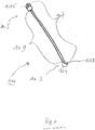
- Fig. 1 shows a guide catheter 100 in a first embodiment.
- the guide catheter 100 has a distal end region 103 and a proximal end region 105.
- a hollow guide section 107 extends from proximal to distal. It corresponds to the continuous part of the guide catheter 100 which has the hollow interior, that is to say the lumen which extends from the distal end to the proximal end.
- the guide section 107 has a straight section 109 and a curved section 111 or consists of these two sections 109, 111.
- the curved section 109 lies in the distal end region 103 Fig. 1
- the curved section 111 forms the distal end of the guide section 107.
- the curved section 111 distal to a curvature which adjoins the straight section 109 again in another if preferably a very short, straight section above.
- the curved section 111 is distal to the straight section 109.
- the curvature can, as in FIG Fig. 1a , which is an enlarged portion of the distal end portion 103 Fig. 1 corresponds, shown, to be around 15 ° to 90 °.
- the distal end of the guide section 107 ends with an opening 113 from which a guide wire guided in the guide section 107 can be guided.
- the proximal end of catheter 100 has an optional valve 115.
- the valve 115 like the guide section 107, is also hollow. Its cavity is aligned with that of the guide section 107, which is why a guide wire can be pushed both through the guide section and through the valve 115.
- Fig. 1a shows the distal end region 103 of the guide catheter 100 of FIG Fig. 1 in an enlarged view.
- the longitudinal axis of the cavity which runs through the straight section 109, is drawn as a dashed line.
- the longitudinal axis of the cavity that defines the curved portion 111 is shown as a dash-dot line.
- Fig. 1a shows that the straight section 109 and the curved section 111 are at an angle ⁇ to one another.
- the angle ⁇ results in the curvature, which is assumed here to be attributable exclusively to the shape of the curved section 111.
- the curved section 111 is continuously curved, and that the curved section 111 also has a straight section in addition to the curvature or ends at the opening 113.
- Fig. 2 shows a hollow needle catheter 200 for use with the guide catheter 100.
- the hollow needle catheter 200 in turn has a hollow guide section, through which a guide wire can be introduced into the interior of the hollow needle catheter 200 and can be moved relative thereto.
- the hollow guide section is at least or finally distributed over a flexible catheter section 201 and a non-flexible hollow needle 203.
- the flexible hollow needle 203 represents the distal end of the hollow needle catheter 200. It can have an inclined cutting edge 205. "Oblique” here means that the circumferential cutting edge of the cutting edge 205 does not describe a round, but an oval surface.
- the hollow needle catheter 200 can be dimensioned in order to be able to be received in the hollow guide section 107 of the guide catheter 100 and to be able to emerge from the opening 113 of the guide catheter 100 with its cutting edge 205 of the hollow needle 203 as well as with the flexible catheter section 201.
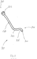
- Fig. 3 shows a positioning catheter 300 according to the invention, in a first embodiment thereof.
- the positioning catheter 300 has a distal end region 301 and a proximal end region 303.
- the positioning catheter 300 has at least or exactly two curvature sections 305 and 307 which are in a common first plane (the drawing plane in FIG Fig. 3 ) and which are each distal to a straight section 309.
- the positioning catheter 300 can have at least or exactly one curvature in a second plane, the second plane being perpendicular to the first plane.
- the curvature in the second plane can be such that the opening 311 is further above or in front of the plane of the drawing Fig. 3 is at least two other sections of the positioning catheter 300 that lie in the plane of the drawing.
- the curvature in the second plane can preferably be between - 45 ° and + 90 °.
- the distal end region 301 has an end opening or opening 311 of a guide section which extends from the opening 311 to a proximal end of the proximal end region 303, optionally up to a valve 313 optionally placed on the proximal end.
- the positioning catheter 300 shown in an exemplary embodiment is curved so that when it is pushed through the interatrial septum 715, its opening 311 stands in front of or in the region of the native mitral valve apparatus (s) 719. Its special curvature allows it to be easily guided into the left atrium and in front of the 719 mitral valve when it is accessed via the 711 brachiocephalic vein or superior 713 vena cave.
- the positioning catheter 300 can already detachably carry the mitral valve implant 600.
- the positioning catheter 300 serves as a guide catheter, through the hollow guide section of which a further catheter, here as a mitral valve catheter 500 or as a mitral valve-carrying catheter 500 denotes, which carries the mitral valve implant 600 until the native mitral valve 719 is guided to its replacement.
- a further catheter here as a mitral valve catheter 500 or as a mitral valve-carrying catheter 500 denotes, which carries the mitral valve implant 600 until the native mitral valve 719 is guided to its replacement.
- the positioning catheter 300 can be designed so stiff that its flexural modulus is stiffer or larger than the flexural modulus of the mitral valve catheter 500, which carries the mitral valve implant 600, so that the positioning catheter 300 in use, i. that is, when the mitral valve implant 600 is passed through its guide portion, it does not lose shape.
- the positioning catheter 300 or its guide section have the same or a lower strength or the same or a lower flexural modulus than the mitral valve implant 600.
- the above-mentioned curvatures or bends of the positioning catheter are shaped in such a way that the distal opening 311 preferably lies directly above the native mitral valve apparatus 719 or in the mitral valve apparatus 719.
- Fig. 3a shows the distal end region 301 and the distal part of the proximal end region 303 of the positioning catheter 300 of FIG Fig. 3 in a slightly enlarged representation.
- the longitudinal axis of the cavity, which runs through the straight section 309, is drawn as a broken line.
- the longitudinal axis of the cavity, which runs through the first curved section 305, is indicated as a dotted line.
- the longitudinal axis of the cavity, which runs through the second curved section 307, is indicated as a dash-dot line.
- Fig. 3a shows that the straight section 309 and the second curved section 307 are at an angle ⁇ to one another.
- the angle ⁇ gives the first curvature, from which it is assumed here that its creation is exclusively attributable to the shape of the second curved section 307.
- Fig. 3a shows that the second curved portion 307 and the first curved portion 305 are at an angle ⁇ to each other.
- the angle ⁇ results in the second curvature, from which it is assumed here that its formation can only be attributed to the shape of the first curved section 305.
- the first curved section 305 is continuously curved, and that it also has a straight section in addition to the curvature or that it ends at the opening 311.
- the angle ⁇ can be between 0 ° and 120 °, preferably 20 ° to 40 °.
- the angle ⁇ can be between 10 ° and 120 °, preferably between 90 ° and 120 °.
- An angle ⁇ which extends between the longitudinal axis of the cavity which runs through the straight section 309 (see the dashed line) and an exit direction for an exit from the opening 311, drawn by means of a dash-circle line, is twice in the plane of the drawing or plane Curvature advantageously between 0 ° (parallel) and 60 °.
- a section 308 located between the first curvature 305 and the second curvature 307 (or between the intersection of the straight lines which give the angles ⁇ and ⁇ ) is, according to the invention, between 2 cm and 6 cm long.
- Fig. 4 shows a hemostasis catheter or balloon catheter 400.
- the balloon catheter 400 has a line section 401 and a balloon section 403 attached thereto and connected in fluid communication.
- the balloon section 403 can be filled with fluid, usually saline solution, via the line section 401 and thereby expanded or widened.
- the balloon section 403 has a hemostatic, absorbable sheath 405, which after use of the balloon catheter 400 remain in the puncture wound and can be resorbed there.
- Balloon section 403 is in Fig. 4 shown expanded.
- Fig. 4a shows the balloon catheter 400 of FIG Fig. 4 in a non-expanded or less expanded state, in which it can be removed from the puncture wound after the fluid or the fluid pressure inside the balloon has been completely or partially released.
- the optional sheath 405 may remain in the puncture wound after deflation of the balloon or balloon portion 403. It can be resorbed there.
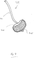
- 5 and 5a show an exemplary mitral valve catheter 500 according to the invention, in a first embodiment thereof.
- the mitral valve catheter 500 has a mitral valve implant 600 in a distal end region 501.
- the mitral valve implant 600 is once in the expanded state of the mitral valve prosthesis ( Fig. 5 ) shown once in a less expanded or folded state ( Fig. 5a ).
- the mitral valve implant 600 is based on a foldable or crimpable stent body, which in 5 and 5a and flap sails, which are not shown in these figures.
- the stent body is preferably made of or has nitinol or another shape memory material.
- the stent body has, for example, three longitudinal connectors or posts 605, which connect an annular distal guide structure 601 and an annular proximal guide structure 603 to one another.
- Reins or strings 617 which also run through or around the annular distal guide structure 601 and the annular proximal guide structure 603 run in an inner longitudinal lumen of the mitral valve catheter 500.
- the strings 617 are provided in order to be able to exert a radially inward pressure on the annular distal guide structure 601 and the annular proximal guide structure 603 with the aim of being able to reduce the diameter of these two guide structures and thus also the diameter of the stent body.
- the described features of the mitral valve implant 600 can be provided on the mitral valve catheter 500 or on the positioning catheter 300 (e.g. on its distal end section) in such a way that the mitral valve leaflets flow through in the distal to proximal direction (based on the arrangement of the mitral valve implant 600 on the catheter, in Fig. 5 allowed from top to bottom), but prevented in the opposite direction (in Fig. 5 from bottom to top).
- the mitral valve implant 600 is thus preferably arranged on the catheter for an implantation in which the catheter coming from the left atrium is pushed towards the native mitral valve 719, not coming from the left ventricle.
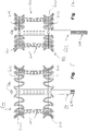
- the 6a to 6f show an embodiment of a method for applying the positioning catheter to a patient.
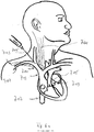
- Fig. 6a shows the puncturing required for the implantation of the mitral valve implant 600.
- the angle between the right sternocleidomastoid 701 and the right clavicle 703 is identified.
- the skin is around 1 cm from the head of the sternocleidomasteideus 701 muscle and at a distance of around 1 cm dotted to the clavicle 703.
- the needle 705 used for the puncture is inserted at an angle of 35-45 ° to the body axis and at an angle of approximately 15 ° to the body plane (preferably aimed at the opposite nipple).
- the needle 705 then punctures the "vein angle" of the vena subclavia 707 and the vena jugularis interna 709, at the union to the vena brachiocephalica 711.
- FIG. 6a The interatrial septum is also designated by the reference number 715, the inferior vena cava by reference number 717 and the mitral valve by the reference number 719.
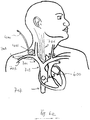
- Fig. 6b shows the preparation of the puncture of the interatrial septum 715.
- the stiff guide catheter 100 which is slightly curved at the distal end, is guided "over the wire” over the brachiocephalic vein 711 and the superior vena cava 713 with the tip or its opening 113 to the interatrial septum 715.
- Fig. 6c shows the state after the puncture of the interatrial septum 715, to which the hollow needle catheter 200 was inserted into the hollow guide section of the rigid guide catheter 100, and wherein the interatrial septum 715 was punctured with the cutting edge 205 of the hollow needle 203 emerging from its opening 113.
- Fig. 6c also shows that a guide wire 800 was pushed into the left atrium via the hollow needle catheter 200 and further into the left ventricle through the opening in the interatrial septum 715 created by puncturing with the hollow needle 203.
- the guide catheter 100 is already half pulled out of the patient's body.
- Dilation of the opening created in the interatrial septum 715 by means of hollow needle 203 can be dilated by means of a dilator or balloon.
- the opening in the interatrial septum 715 allows the distal end section of the positioning catheter 300 to be introduced "over the wire” into the brachiocephalic vein and the superior vena cava into the left atrium.
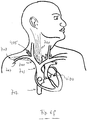
- Fig. 6d shows this state.
- Fig. 6d shows that the bend of the positioning catheter 300 according to the invention makes it possible to position its open end exactly above or also in the native mitral valve apparatus.
- the mitral valve prosthesis 600 is advanced along the guide section through the interior of the positioning catheter 300 and anchored in the native mitral valve apparatus 719.
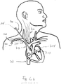
- Fig. 6e shows a condition of the patient after implantation of the mitral valve implant 600.
- a hemostatic balloon catheter 400 is advanced into the subcutaneous tissue up to just before the puncture site of the 711 brachiocephalic vein via the existing access. This is advantageously done via a guide wire, which in Fig. 6e is not shown.
- the in Fig. 6e The state shown thus corresponds to the state after insertion of the balloon catheter 400 and after removal of the guide wire, if one was used.
- the balloon section 403 is filled and thus expanded in the subcutaneous tissue and leads to an immediate hemostasis.
- the hemostatic sheath is preferably resorbable.
Landscapes
- Health & Medical Sciences (AREA)
- Cardiology (AREA)
- Oral & Maxillofacial Surgery (AREA)
- Transplantation (AREA)
- Engineering & Computer Science (AREA)
- Biomedical Technology (AREA)
- Heart & Thoracic Surgery (AREA)
- Vascular Medicine (AREA)
- Life Sciences & Earth Sciences (AREA)
- Animal Behavior & Ethology (AREA)
- General Health & Medical Sciences (AREA)
- Public Health (AREA)
- Veterinary Medicine (AREA)
- Prostheses (AREA)
- Media Introduction/Drainage Providing Device (AREA)
Description
- Die vorliegende Erfindung betrifft einen medizinischen Positionierkatheter gemäß dem Oberbegriff des Anspruchs 1.
- Die vorliegende Erfindung betrifft Katheter zum Ersatz nativer Mitralklappen durch künstliche Mitralklappen, hierin gleichbedeutend auch als Mitralklappenimplantate oder Mitralklappenprothesen bezeichnet.
- Während man in der Vergangenheit Aortenklappenimplantate ausschließlich chirurgisch implantiert hat, hat die kathetergestützte Aortenklappenimplantation über die letzten Jahre zunehmend großen Erfolg erfahren. Mittlerweile werden allein in Deutschland derzeit jährlich rund 10.000 Aortenklappenprothesen unter Einsatz eines Katheters implantiert, auf dem das Implantat lösbar befestigt zum Implantationtionsort transportiert wird. Die Implantation mittels Katheter hat dabei zahlreiche, dem Fachmann bekannte Vorteile.
- Der Zugang für den Katheter erfolgt zumeist über die Femoralarterie. Da die Femoralarterie nur einen mäßig großen Durchmesser hat, dürfen die verwendeten Katheter nicht dicker als ca. 28 Fr. ("French") sein. Ist die Femoralarterie erkrankt oder zu dünn, so kann alternativ der transapikale Zugang über die Herzspitze gewählt werden.
- Die auf dem Katheter zusammengefalteten Klappenprothesen haben derzeit einen Durchmesser von ca. 21 Fr.
- Seit geraumer Zeit bestehen nicht zuletzt bei der Anmelderin der vorliegenden Anmeldung Bestrebungen, ein Herzklappenimplantat für den kathetergestützten Ersatz der nativen Mitralklappe zu entwickeln. Neben den erheblich größeren Herausforderungen bei der Entwicklung einer Mitralklappenprothese, gemessen an der zwischenzeitlich abgeschlossenen Entwicklung einsetzbarer Aortenklappenprothesen, aufgrund der ungleich schwierigeren Verankerung und Abdichtung der Mitralklappenprothese stellt auch das Einführen der gefalteten Mitralklappenprothese eine große Herausforderung dar.
- Wie für die Aortenklappenprothese gibt es zwei Möglichkeiten für einen Zugang zum Implantationsort. Hierbei handelt es sich wiederum um die Herzspitze ("transapikal") und die Leistengefäße ("transfemoral").
- So kann auch die Mitralklappenprothese über die Herzspitze eingeführt werden. Der Zugang zur Herzspitze ist leicht herzustellen, ein bis zu 40 Fr. starker Katheter kann ohne Schwierigkeiten eingeführt werden. Da die Klappenprothese hierbei jedoch über die Herzkammer ("Ventrikel") in den nativen Klappenapparat eingeführt wird, können die dort zahlreich vorliegenden Sehnenfäden die korrekte Positionierung der Herzklappe erschweren.
- Alternativ kann die Mitralklappenprothese über die Leistenvene, die Vena femoralis, eingeführt werden. Die Vena femoralis hat einen ausreichenden Durchmesser, der es ermöglicht, auch größere Katheter, wie im Fall der Mitralklappenprothese notwendig, einzuführen. Der Mitralklappen-Katheter muss über die Vena cava superior zur Vorhofscheidewand, dem interatrialen Septum, des Herzens geführt werden. Dort wird die Vorhofscheidewand mittels Punktion geöffnet und der Katheter vom rechten Vorhof in den linken Vorhof geführt. Im linken Vorhof muss die Spitze des Katheters, bezogen auf andere Abschnitte des Katheters, eine Kurve um mehr als 270° durchführen, damit die Spitze des Katheters zusammen mit der hierauf lösbar befestigten, zusammengefalteten Mitralklappenprothese in den nativen Mitralklappenapparat eingeführt werden kann. Derartige transvenöse, transseptale Implantationen einer Mitralklappenprothese scheiterten in erster Linie an dem o. g. überstumpfen oder steilen Winkel im linken Vorhof, welchen der Katheter vollziehen muss. Weder die bisher entwickelten Katheter noch die vergleichsweise großen, gefalteten Klappenprothesen erlauben den notwendigen Winkel im linken Vorhof zu vollziehen.
- Die vorgenannten technischen Schwierigkeiten hinsichtlich Katheter und/oder Mitralklappenprothese, wenn auf dem Katheter für die Implantation über die venöse Gefäßseite vorgesehen, werden bis zu ihrer derzeit nicht in Aussicht stehenden Lösung dazu führen, dass Mitralklappenprothesen bis auf weiteres neben dem transapikalen Zugang auch über einen weiteren Zugang implantiert werden müssen, welcher eine Thorakoskopie erfordert. In den mittels Thorakoskopie eröffneten Brustkorb wird das Mitralklappenimplantat über den linken Vorhof direkt in den nativen Mitralklappenapparat eingeführt. Hierzu ist jedoch eine Thorakoskopie mit Eröffnen des Brustkorbes, dem Kollabieren der Lunge und damit eine mechanische Beatmung notwendig. Die Vorteile, die eine Implantation mittels Katheter bieten kann, sind hiermit natürlich nicht zu erzielen. Die Druckschrift
WO 2011/109813 A2 offenbart ein Verfahren, eine Vorrichtung und ein System zum gezielten Heranführen einer künstlichen Herzklappe an eine defekte Herzklappe, wobei dazu ebenfalls ein medizinischer Positionierkatheter verwendet wird. Der in derWO 2011/109813 A2 offenbarte Positionierkatheter ist jedoch nicht für den Einsatz bei einer nativen Mitralklappe geeignet. - Die Aufgabe der vorliegenden Erfindung ist, eine Vorrichtung vorzuschlagen, mittels welcher auch eine Mitralklappenprothese mittels Katheter implantiert werden kann.
- Die erfindungsgemäße Aufgabe kann durch einen Positionierkatheter mit den Merkmalen des Anspruchs 1 gelöst werden.
- Der erfindungsgemäße medizinischer Positionierkatheter dient zur Verwendung beim Implantieren eines Mitralklappenimplantats oder zum Reparieren eines Herzdefekts oder einer Mitralklappe.
- Der Positionierkatheter weist einen distalen Endbereich, welcher ein distales Ende des Positionierkatheters umfasst, und einen proximalen Endbereich, welcher ein proximales Ende des Positionierkatheters umfasst, auf.
- Der Positionierkatheter weist ferner einen hohl ausgestalteten Führungsabschnitt auf. Der Führungsabschnitt weist einen geraden Abschnitt und wenigstens einen ersten Krümmungsabschnitt und einen zweiten Krümmungsabschnitt auf oder besteht hieraus.
- Der erste Krümmungsabschnitt und der zweite Krümmungsabschnitt liegen im distalen Endbereich. Alternativ bilden der erste Krümmungsabschnitt oder der zweite Krümmungsabschnitt das distale Ende des Positionierkatheters aus. Sowohl der erste Krümmungsabschnitt als auch der zweite Krümmungsabschnitt sind distal des geraden Abschnitts angeordnet.
- Der erste Krümmungsabschnitt bewirkt eine Biegung oder Krümmung des Führungsabschnitts um 10 bis 120°, bevorzugt um 90 bis 120°.
- Erfindungsgemäß bewirkt der zweite Krümmungsabschnitt eine Biegung oder Krümmung des Führungsabschnitts um 20 bis 40° bewirkt und zwischen dem ersten Krümmungsabschnitt und dem zweiten Krümmungsabschnitt ist ein 2 - 6 cm langer Abschnitt (308) angeordnet.
- Die erfindungsgemäße Ausgestaltung des distalen Endbereichs des medizinischen Positionierkatheters ermöglicht es, den erfindungsgemäßen Positionierkatheter beim Implantieren eines Mitralklappenimplantats oder zum Reparieren eines Herzdefekts oder einer Mitralklappe zu verwenden. Aus dem Stand der Technik bekannte Positionierkatheter können dazu aufgrund abweichender Gestaltung des distalen Endbereichs nicht verwendet werden.
- Wenn hierin von einem "Venenwinkel" die Rede ist, so kann hiermit jener Bereich verstanden werden, in welchem sich die Vena subclavia und Vena jugularis interna zur Vena brachiocephalica vereinen. Wird der Venenwinkel punktiert, so kann hierunter beispielhaft ein Punktieren eines beliebigen der vorgeannten Gefäße im Bereich der Vereinigung verstanden werden.
- Wenn hierin von paarweise (sinistra, dextra) vorhandenen Gefäßen die Rede ist, so ist im Zweifel davon auszugehen, dass hierin die "dextra"-Form gemeint ist.
- Die Begriffe "distal" und "proximal" beziehen sich hierin auf die Verwendung des betreffenden Katheters. In den hier beigefügten Figuren, mit Ausnahme der
Fig. 5 und derFig. 5a , liegt das proximale Ende eines jeden Katheters im Zweifel immer im oberen Bereich der Figur, während das distale Ende im Zweifel immer im unteren Bereich der Figur liegt. InFig. 5 und Fig. 5a ist dies umgekehrt. - Erfindungsgemäße Ausführungsformen können eines oder mehrere der im Folgenden genannten Merkmale in beliebiger Kombination aufweisen, sofern eine konkrete Kombination für den Fachmann nicht als offenkundig technisch unmöglich erkennbar ist. Auch die Gegenstände der Unteransprüche geben jeweils erfindungsgemäße Ausführungsformen an.
- Bei allen folgenden Ausführungen ist der Gebrauch des Ausdrucks "kann sein" bzw. "kann haben" usw. synonym zu "ist vorzugsweise" bzw. "hat vorzugsweise" usw. zu verstehen und soll erfindungsgemäße Ausführungsformen erläutern.
- Wann immer hierin Zahlenworte genannt werden, so versteht der Fachmann diese als Angabe einer zahlenmäßig unteren Grenze. Sofern dies zu keinem für den Fachmann erkennbaren Widerspruch führt, liest der Fachmann daher beispielsweise bei der Angabe "ein" oder "einem" stets "wenigstens ein" oder "wenigstens einem" mit. Dieses Verständnis ist ebenso von der vorliegenden Erfindung mit umfasst wie die Auslegung, dass ein Zahlenwort wie beispielsweise "ein" alternativ als "genau ein" gemeint sein kann, wo immer dies für den Fachmann erkennbar technisch möglich ist. Beides ist von der vorliegenden Erfindung umfasst und gilt für alle hierin verwendeten Zahlenworte.
- In einigen erfindungsgemäßen, beispielhaften Ausführungsformen weist der Positionierkatheter ein Ventil auf, das den geraden Abschnitt nach proximal abschließt.
- In manchen erfindungsgemäßen, beispielhaften Ausführungsformen sind der erste Krümmungsabschnitt und der zweite Krümmungsabschnitt des Positionierkatheters gegensinnig gekrümmt, insbesondere bezogen auf eine Ebene. "Gegensinnig" kann sich dabei auf das Vorzeichen der Krümmung (plus, minus) oder des Krümmungswinkels beziehen. "Gegensinnig" kann, beispielsweise bei bildlicher Darstellung der Ebene, in welcher die Krümmungen liegen, als konvex versus konkav oder als "nach links" versus "nach rechts" zu verstehen sein.
- In einigen erfindungsgemäßen, beispielhaften Ausführungsformen ist sind der Positionierkatheter oder sein Führungsabschnitt maximal 80 cm, bevorzugt maximal 60 cm, besonders bevorzugt maximal 45 cm lang.
- In manchen erfindungsgemäßen, beispielhaften Ausführungsformen sind der Positionierkatheter oder sein Führungsabschnitt nicht-flexibel, nicht-elastisch oder steif.
- In einigen erfindungsgemäßen, beispielhaften Ausführungsformen haben der Positionierkatheter, sein Führungsabschnitt, der erste Krümmungsabschnitt und/oder der zweite Krümmungsabschnitt eine shape-memory-Funktion oder - form, bestehen aus einem shape-memory-Material oder weisen ein solches auf.
- In manchen erfindungsgemäßen, beispielhaften Ausführungsformen weist der Positionierkatheter ferner ein Ventil auf, das den geraden Abschnitt nach proximal abschließt.
- In einigen erfindungsgemäßen, beispielhaften Ausführungsformen trägt der Positionierkatheter in seinem distalen Endbereich lösbar ein Mitralklappenimplantat. Er hat hierzu einen Aufnahmeabschnitt zum Aufnehmen des Mitralklappenimplantats.
- In manchen erfindungsgemäßen, beispielhaften Ausführungsformen verläuft die Durchströmungsrichtung des Mitralklappenimplantats, wenn dieses auf dem Positionierkatheter vorliegt, vom proximalen Endbereich zum distalen Endbereich des Positionskatheters.
- Wenn hierin von der Durchströmungsrichtung des Mitralklappenimplantats die Rede ist, so kann diese als die Richtung verstanden werden, in welcher die Klappen des Implantats nach Implantation einen Durchfluss erlauben, was sie im implantierten Zustand in der hierzu entgegen gesetzten Richtung nicht erlauben würden oder sollten. Die Durchströmungsrichtung haftet dem Implantat unveränderlich daher an, gleich ob es implantiert oder noch auf dem Katheter vorliegt, gleich ob es tatsächlich von Blut durchströmt wird, oder noch nicht. So verläuft beispielsweise die Durchströmungsrichtung des Mitralklappenimplantats 600 der
Fig. 6e und6f bezogen auf die Figur jeweils von oben nach unten. Die Durchströmungsrichtung ist dabei eine strukturelle Eigenschaft des Implantats im Sinne einer Richtung, in welcher das Implantat durchströmbar ist. - In manchen erfindungsgemäßen, beispielhaften Ausführungsformen verläuft die Durchströmungsrichtung des Mitralklappenimplantats, wenn dieses auf dem Mitralklappen-Katheter vorliegt, vom proximalen Endbereich zum distalen Endbereich des Mitralklappen-Katheters.
- Der Positionierkatheter ist in bestimmten erfindungsgemäßen Ausführungsformen zwecks - angesichts seines eher steifen Charakters - optimaler Handhabbarkeit nicht über 80 cm lang (gemessen von seinem proximalen Ende bis zu seinem distalen Ende), vorzugsweise zwischen 45 und 60 cm lang.
- Der Positionierkatheter kann sterilisiert sein, insbesondere mittels Strahlung, mittels Dampf und/oder mittels Temperatur.
- Die Sterilisation hat dabei vorzugsweise werkseitig stattgefunden. Dies erlaubt eine kostengünstige und automatisierte Sterilisation, die wenig für menschliche Fehler anfällig ist.
- Der Positionierkatheter kann aus Kunststoff, Polymer, Polyäthylen, Polypropylen, Polyvinylchlorid (PVC), oder Polyamid sein.
- Der Positionierkatheter kann einen expandierbaren inneren Durchmesser aufweisen. Dies ist möglich durch eine Elastizität des Rohres oder durch ein Auffalten des Rohres. Entsprechende Ausgestaltungen und Einrichtungen können vorgesehen sein. Somit kann ein Positionierkatheter mit dünnem Durchmesser eingeführt werden. Wird das Mitralklappenimplantat mit einem größeren Durchmesser über den flexiblen Positionierkatheter vorgeschoben, so dehnt sich der Positionierkatheter nur über eine kurze Strecke, nämlich dort, wo das Implantat gerade liegt, und nur so lange, wie es vorgeschoben wird. Dadurch wird das umgebende Gewebe weniger belastet. Noch wichtiger ist, dass der Blutfluss in der Vena brachiocephalika und der Vena cava superior bei liegendem Positionierkatheter vorteilhaft nicht beeinflusst wird. Nur während der kurzen Zeit des Vorschiebens des dickeren Implantates und während sich der flexible Positionierkatheter entsprechend aufdehnt wird der Blutfluss in den erwähnten Venen behindert. Sobald das Implantat den Katheter passiert hat, besteht keine weitere Belastung des Gewebes (Einstichstelle oder Vorhofscheidewand) mehr und der Blutfluss ist nicht mehr behindert.
- Der hiermit vorgeschlagene erfindungsgemäße Positionierkatheter erlaubt erstmals eine Mitralklappenimplantation, welche weder transfemoral noch transapikal erfolgt. Dabei können aufgrund der Ausgestaltung des erfindungsgemäßen Positionierkatheters einige der eingangs genannten Schwierigkeiten bei der Implantation aufgehoben oder doch zumindest abgemildert werden.
- So erlaubt der erfindungsgemäße Positionierkatheter erstmals eine Implantation über einen supraclaviculären Zugang. Der supraclaviculäre Zugang kann mehrere wesentliche Vorteile bieten. Zu ihnen zählt, dass es im Vergleich zur subclaviculären Punktion klare Orientierungspunkte für die supraclaviculäre Punktion gibt. Die Punktion erfolgt aus der Richtung des Kopfes des Patienten und nicht von der Seite.
- Zu ihnen zählt ferner, dass die Entfernung von der Hautoberfläche zur Vene kürzer und die punktierte Vena brachiocephalica hier erheblich dicker ist und sich besser für das Einbringen großer Katheter eignet. Möglich wird dieser Weg jedoch erst durch die spezielle Form der hiermit vorgeschlagenen Katheter.
- Zu ihnen zählt ferner, dass ein Katheter zum Einsatz kommen kann, der jedenfalls bis er den rechten Vorhof des Herzens erreicht, gerade verlaufen darf. Erst zum Punktieren des interatrialen Septums muss er vergleichsweise geringfügig gekrümmt sein.
- Zu den Vorteilen zählt ferner, dass die Entfernung zur Lunge größer ist als etwa bei dem subclaviculären Zugang, was das Risiko einer Verletzung der Lunge vermindert.
- Ein Führungskatheter, welcher zur Vorbereitung der Punktion des interatrialen Septums dient, erlaubt eine einfache, schnelle Punktion des interatrialen Septums nach geradem, supraklavikulärem Zugang.
- Der supraclaviculäre Zugang hat gerade für die Implantation einer kathetergestützten Klappenprothese erhebliche Vorteile, die einen perkutane, d.h. mittels Gefäßpunktion durchgeführte interventionelle Implantation einer Mitralklappenprothese möglich macht. Es ist ein relativ gerader Weg von der supraclaviculären Punktionsstelle, über den Venenwinkel, der Vena brachiocepahlica und der Vena cava superior zum rechten Vorhof und dem interatrialen Septum. Nach Durchdringen des Septums muss der Katheter nur leicht gebogen werden, um in den linken Vorhof zu gelangen. Hier ist wiederum nur eine leichte Biegung notwendig, um in den Mitralklappenapparat zu gelangen.
- Im Vergleich zu einem transfemoralen Zugang ist die Entfernung von der Punktionsstelle zum Mitralklappenapparat mit nur ca. 15-20 cm sehr kurz.
- Der Weg von der Punktion der Haut zum Venenwinkel ist sehr kurz. Dort hat die Vena brachiocephalica bereits einen großen Durchmesser und nach Zusammenfluss mit der Vena anonyma erweitet sie sich weiter zur Vena cava superior. Der Durchmesser der Vena brachiocephalica ist groß genug um Katheter mit einem Durchmesser von 40Fr. einzuführen.
- Der supraclaviculäre Zugang erlaubt das Einführen eines großkalibrigen Mitralklappen-Katheters. Die Implantation kann unvergleichlich gut kontrolliert werden, da der Weg zum nativen Mitralklappenapparat kurz und vor allem auch gerade ist. Es ist kein starkes Verbiegen des Katheters notwendig, um in den nativen Mitralklappenapparat vorzudringen.
- Um einen zentralen venösen Zugang zu erhalten wird üblicherweise die Vena subclavia punktiert. Die Vena subclavia liegt unter und hinter dem Schlüsselbein. Dieser Zugang wird üblicherweise genutzt, um einen großen Katheter einzuführen über den Flüssigkeiten und Medikamente zentral dem venösen Blut zugeführt werden können. Dieser Zugang wird jedoch auch genutzt, um Schrittmacherkabel an das Herz zu führen oder um eine Hämodialyse durchzuführen bis hin zum Anschluss einer Herz-Lungen-Maschine. Dies ist möglich, da die Vena subclavia einen großen Durchmesser hat und keine Venenklappen besitzt. Die Vena subclavia hat bei nahezu allen Patienten die gleiche Lage und ist so relativ sicher zu finden und zu punktieren.
- Dennoch gibt es Situationen, in denen die Vena subclavia nicht für einen Zugang genutzt werden kann, z.B. nach Traumen, bei Verschluss oder bei liegenden Schrittmacherkabel.
- Die vorliegende Erfindung erlaubt es aufgrund des hiermit vorgeschlagenen erfindungsgemäßen Positionierkatheter, erstmals vom supraclaviculären Zugang Gebrauch zu machen.
- Die vorliegende Erfindung wird im Folgenden anhand der beigefügten Zeichnungen, in welcher identische Bezugszeichen gleiche oder ähnliche Bauteile bezeichnen, exemplarisch erläutert. In den zum Teil stark vereinfachten Figuren gilt:
-
Fig. 1 : zeigt einen Führungskatheter in einer ersten Ausführungsform; -
Fig. 1a : zeigt eine Vergrößerung eines Abschnitts ausFig. 1 ; -
Fig. 2 : zeigt einen Hohlnadelkatheter zur Verwendung mit dem Führungskatheter; -
Fig. 3 : zeigt einen erfindungsgemäßen Positionierkatheter, in einer ersten Ausführungsform hiervon; -
Fig. 3a : zeigt den distalen Endbereich und den distalen Teil des proximalen Endbereichs des Positionierkatheters derFig. 3 in leicht vergrößerter Darstellung; -
Fig. 4 : zeigt einen Hämostasekatheter oder Ballonkatheter,; -
Fig. 4a : zeigt den Ballonkatheter derFig. 4 in einem nicht oder weniger expandierten Zustand; -
Fig. 5, 5a : zeigen einen Mitralklappen-Katheter, in einer ersten Ausführungsform hiervon, in expandiertem Zustand der Mitralklappenprothese (Fig. 5 ) und in weniger expandiertem Zustand (Fig. 5a ); und -
Fig. 6a-6f : zeigen eine Ausführungsform eines Verfahrens zum Verwenden des Positionierkatheters. -
Fig. 1 zeigt einen Führungskatheter 100 in einer ersten Ausführungsform. - Der Führungskatheter 100 weist einen distalen Endbereich 103 und einen proximalen Endbereich 105 auf.
- Von proximal nach distal erstreckt sich ein hohl ausgestalteten Führungsabschnitt 107. Er entspricht dem durchgehenden Teil des Führungskatheters 100, der das hohle Innere hat, also das Lumen, das sich vom distalen Ende bis zum proximalen Ende zieht.
- Der Führungsabschnitt 107 einen geraden Abschnitt 109 und einen gekrümmten Abschnitt 111 auf oder besteht aus diesen beiden Abschnitten 109, 111.
- Der gekrümmte Abschnitt 109 liegt im distalen Endbereich 103. In der
Fig. 1 gezeigten exemplarischen Ausführungsform bildet der gekrümmte Abschnitt 111 das distale Ende des Führungsabschnitts 107. In anderen exemplarischen Ausführungsformen, welche hier nicht gezeigt sind, geht der gekrümmte Abschnitt 111 distal einer Krümmung, welche sich an den geraden Abschnitt 109 anschließt, erneut in einen weiteren, wenn gleich vorzugsweise sehr kurzen, geraden Abschnitt über. - Der gekrümmte Abschnitt 111 liegt distal zum geraden Abschnitt 109. Die Krümmung kann, wie in
Fig. 1a , welche einem vergrößerten Abschnitt des distalen Endbereichs 103 ausFig. 1 entspricht, gezeigt, rund 15° bis 90° betragen. - Das distale Ende des Führungsabschnitts 107 endet mit einer Öffnung 113, aus welcher ein im Führungsabschnitt 107 geführter Führungsdraht geführt werden kann.
- Das proximale Ende des Katheters 100 weist ein optionales Ventil 115 auf. Das Ventil 115 ist wie der Führungsabschnitt 107 ebenfalls hohl. Sein Hohlraum fluchtet mit jenem des Führungsabschnitts 107, weshalb ein Führungsdraht sowohl durch den Führungsabschnitt als auch durch das Ventil 115 hindurch geschoben werden kann.
-
Fig. 1a zeigt den distalen Endbereich 103 des Führungskatheters 100 derFig. 1 in vergrößerter Darstellung. - Die Längsachse des Hohlraums, welcher den geraden Abschnitt 109 durchzieht, ist als Strichlinie gezeichnet. Die Längsachse des Hohlraums, welcher den gekrümmten Abschnitt 111 durchzieht, ist als Strich-Punkt-Linie angedeutet.
Fig. 1a zeigt, dass der gerade Abschnitt 109 und der gekrümmte Abschnitt 111 unter einem Winkel α zueinanderstehen. Der Winkel α ergibt die Krümmung, von welcher hier angenommen wird, dass ihr Entstehen ausschließlich der Form des gekrümmten Abschnitts 111 zuzurechnen ist. Es ist erfindungsgemäß sowohl vorgesehen, dass der gekrümmte Abschnitt 111 durchgehend gekrümmt ist, als auch dass der gekrümmte Abschnitt 111 neben der Krümmung auch einen geraden Abschnitt aufweist oder hiermit an der Öffnung 113 endet. -
Fig. 2 zeigt einen Hohlnadelkatheter 200 zur Verwendung mit dem Führungskatheter 100. - Der Hohlnadelkatheter 200 weist wiederum einem hohlen Führungsabschnitt auf, durch welchen ein Führungsdraht in das Innere des Hohlnadelkatheters 200 eingebracht und relativ zu zu diesem bewegt werden kann.
- Der hohle Führungsabschnitt ist wenigstens oder abschließend auf einen flexiblen Katheterabschnitt 201 und eine nicht flexible Hohlnadel 203 verteilt. Die flexible Hohlnadel 203 stellt das distale Ende des Hohlnadelkatheters 200 dar. Sie kann eine schräg verlaufende Schneide 205 aufweisen. "Schräg" bedeutet hier, dass die umlaufende Schneidkante der Schneide 205 keine runde, sondern eine ovale Fläche umschreibt.
- Der Hohlnadelkatheter 200 kann dimensioniert sein, um im hohlen Führungsabschnitt 107 des Führungskatheters 100 aufgenommen werden zu können und um sowohl mit seiner Schneide 205 der Hohlnadel 203 als auch mit dem flexibler Katheterabschnitt 201 aus der Öffnung 113 des Führungskatheters 100 austreten zu können.
-
Fig. 3 zeigt einen erfindungsgemäßen Positionierkatheter 300, in einer ersten Ausführungsform hiervon. - Der Positionierkatheter 300 weist einen distalen Endbereich 301 und einen proximalen Endbereich 303 auf.
- Anders als der Führungskatheter 100 der
Fig. 1 weist der Positionierkatheter 300 wenigstens oder genau zwei Krümmungsabschnitte 305 und 307 auf, welche in einer gemeinsamen ersten Ebene (der Zeichenebene inFig. 3 ) liegen und welche jeweils distal zu einem geraden Abschnitt 309 liegen. - Der Positionierkatheter 300 kann zusätzlich zu der vorstehend genannten Krümmung, welche in der ersten Ebene liegt, wenigstens oder genau eine Krümmung in einer zweiten Ebene aufweisen, wobei die zweite Ebene senkrecht auf der ersten Ebene steht. Die Krümmung in der zweiten Ebene kann dergestalt sein, dass die Öffnung 311 weiter über oder vor der Zeichenebene der
Fig. 3 steht als wenigstes zwei andere Abschnitte des Positionierkatheters 300, die in der Zeichenebene liegen. Die Krümmung in der zweiten Ebene kann vorzugsweise zwischen - 45° und + 90° betragen. - Der distale Endbereich 301 weist eine Endöffnung oder Öffnung 311 eines Führungsabschnitts auf, welcher sich von der Öffnung 311 bis zu einem proximalen Ende des proximalen Endbereichs 303 erstreckt, ggf. bis ein auf das proximale Ende optional aufgesetztes Ventil 313.
- Der in
Fig. 3 in exemplarischer Ausgestaltung gezeigte Positionierkatheter 300 ist gekrümmt, um, wenn er durch das interatriale Septum 715 hindurch geschoben wird, mit seiner Öffnung 311 vor dem, oder im Bereich des, nativen Mitralklappenapparat(s) 719 zu stehen. Seine besondere Krümmung erlaubt es, ihn bei Zugang über die Vena brachiocephalica 711 oder Vena cave superior 713 auf einfache Weise bis in den linken Vorhof und vor die Mitralklappe 719 zu leiten. Dabei kann bereits der Positionierkatheter 300 das Mitralklappenimplantat 600 lösbar tragen. In einer alternativen Ausgestaltung ist vorgesehen, dass der Positionierkatheter 300 als Führungskatheter dient, durch dessen hohlen Führungsabschnitt hindurch ein weiterer Katheter, hierin als Mitralklappen-Katheter 500 oder als mitralklappentragender Katheter 500 bezeichnet, welcher das Mitralklappenimplantat 600 trägt, bis vor die native Mitralklappe 719 zu deren Ersatz geführt wird. - Der Positionierkatheter 300 kann derart steif ausgestaltet sein, dass sein Biegemodul steifer oder größer ist als das Biegemodul des Mitralklappen-Katheters 500, welcher das Mitralklappenimplantat 600 trägt, so dass der Positionierungskatheter 300 im Gebrauch, d. h., wenn das Mitralklappenimplantat 600 durch dessen Führungsabschnitt geführt wird, nicht an Form verliert.
- In einigen erfindungsgemäßen Ausführungsformen ist jedoch das Gegenteil der Fall: Der Positionierkatheter 300 oder sein Führungsabschnitt haben dieselbe oder eine niedrigere Festigkeit oder dasselbe oder ein niedrigeres Biegemodul als das Mitralklappenimplantat 600.
- Die vorstehend genannten Krümmungen oder Biegungen des Positionierkatheters sind derart geformt, dass die distale Öffnung 311 vorzugweise direkt oberhalb des nativen Mitralklappenapparats 719 oder im Mitralklappenapparat 719 zu liegen kommt.
-
Fig. 3a zeigt den distalen Endbereich 301 und den distalen Teil des proximalen Endbereichs 303 des Positionierkatheters 300 derFig. 3 in leicht vergrößerter Darstellung. - Die Längsachse des Hohlraums, welcher den geraden Abschnitt 309 durchzieht, ist als Strichlinie gezeichnet. Die Längsachse des Hohlraums, welcher den ersten gekrümmten Abschnitt 305 durchzieht, ist als Punktlinie angedeutet. Die Längsachse des Hohlraums, welcher den zweiten gekrümmten Abschnitt 307 durchzieht, ist als Strich-Punkt-Linie angedeutet.
-
Fig. 3a zeigt, dass der gerade Abschnitt 309 und der zweite gekrümmte Abschnitt 307 unter einem Winkel β zueinanderstehen. Der Winkel β ergibt die erste Krümmung, von welcher hier angenommen wird, dass ihr Entstehen ausschließlich der Form des zweiten gekrümmten Abschnitts 307 zuzurechnen ist. -
Fig. 3a zeigt, dass der zweite gekrümmte Abschnitt 307 und der erste gekrümmte Abschnitt 305 unter einem Winkel γ zueinanderstehen. Der Winkel γ ergibt die zweite Krümmung, von welcher hier angenommen wird, dass ihr Entstehen ausschließlich der Form des ersten gekrümmten Abschnitts 305 zuzurechnen ist. - Es ist erfindungsgemäß sowohl vorgesehen, dass der erste gekrümmte Abschnitt 305 durchgehend gekrümmt ist, als auch dass er neben der Krümmung auch einen geraden Abschnitt aufweist oder hiermit an der Öffnung 311 endet.
- Der Winkel β kann zwischen 0° und 120°, vorzugsweise 20° bis 40° betragen.
- Der Winkel γ kann zwischen 10° und 120°, vorzugsweise zwischen 90° und 120° betragen.
- Ein Winkel µ welcher sich zwischen der Längsachse des Hohlraums, welcher den geraden Abschnitt 309 durchzieht (siehe die Strichlinie) und einer Austrittsrichtung für einen Austritt aus der Öffnung 311, gezeichnet mittels Strich-Kreis-Linie, beträgt in der Zeichenebene oder der Ebene der doppelten Krümmung vorteilhaft zwischen 0° (parallel) und 60°.
- Ein zwischen der ersten Krümmung 305 und der zweiten Krümmung 307 (oder zwischen dem Schnittpunkt der Geraden, welche die Winkel β und γ ergeben) gelegener Abschnitt 308 ist erfindnungsgemäß zwischen 2 cm und 6 cm lang.
-
Fig. 4 zeigt einen Hämostasekatheter oder Ballonkatheter 400. - Der Ballonkatheter 400 hat einen Leitungsabschnitt 401 und einen hieran angesetzten und in Fluidkommunikation verbundenen Ballonabschnitt 403.
- Der Ballonabschnitt 403 kann mittels Fluid, zumeist Kochsalzlösung, über den Leitungsabschnitt 401 befüllt und hierdurch expandiert oder aufgeweitet werden.
- Optional weist der Ballonabschnitt 403 eine hämostatische, resorbierbare Hülle 405 auf, welche nach Einsatz des Ballonkatheters 400 in der Punktionswunde verbleiben und dort resorbiert werden kann.
- Der Ballonabschnitt 403 ist in
Fig. 4 expandiert gezeigt. -
Fig. 4a zeigt den Ballonkatheter 400 derFig. 4 in einem nicht oder weniger expandierten Zustand, in welchem er nach vollständigem oder teilweisem Ablassen des Fluids oder des im Balloninneren herrschenden Fluiddrucks aus der Punktionswunde entfernt werden kann. Die optionale Hülle 405 kann nach Deflation des Ballons oder Ballonabschnitts 403 in der Punktionswunde zurückbleiben. Sie kann dort resorbiert werden. -
Fig. 5 und Fig. 5a zeigen einen exemplarischen erfindungsgemäßen Mitralklappen-Katheter 500, in einer ersten Ausführungsform hiervon. - Der Mitralklappen-Katheter 500 weist in einem distalen Endbereich 501 ein Mitralklappenimplantat 600 auf.
- Das Mitralklappenimplantat 600 ist einmal im expandierten Zustand der Mitralklappenprothese (
Fig. 5 ) gezeigt, einmal in weniger expandiertem oder gefaltetem Zustand (Fig. 5a ) . - Das Mitralklappenimplantat 600 basiert auf einem faltbaren oder crimpbaren Stentkörper, welcher in
Fig. 5 und Fig. 5a gezeigt ist, und Klappensegeln, welche in diesen Figuren nicht gezeigt sind. - Der Stentkörper ist vorzugsweise aus Nitinol oder einem anderen Shape-Memory-Material gefertig oder weist ein solches auf.
- Der Stentkörper weist beispielhaft drei Längsverbinder oder Posts 605 auf, welche eine ringförmige distale Führungsstruktur 601 und eine ringförmige proximale Führungsstruktur 603 miteinander verbinden.
- Durch oder um die ringförmige distale Führungsstruktur 601 und die ringförmige proximale Führungsstruktur 603 laufen Zügel oder Strings 617, welche auch in einem inneren Längslumen des Mitralklappen-Katheters 500 verlaufen. Die Strings 617 sind vorgesehen, um hiermit eine radial nach innen wirkenden Druck auf die ringförmige distale Führungsstruktur 601 und die ringförmige proximale Führungsstruktur 603 ausüben zu können mit dem Ziel, den Durchmesser dieser beiden Führungsstrukturen und damit auch den Durchmesser des Stentkörpers verringern zu können.
- Für Details dieser beispielhaften der Mitralklappe wird auf die Ausführungen zur Herzklappe verwiesen, welche sich in der
WO 2009/109348 A1 oder derWO 2015/014960 A1 finden, deren diesbezügliche Offenbarungen hiermit zum Gegenstand gemacht werden. - Losgelöst von allen mit Bezug auf
Fig. 5 beschriebenen Merkmalen des Mitralklappenimplantats 600 kann dieses auf dem Mitralklappen-Katheter 500 oder auf dem Positonierkatheter 300 (z. B. auf dessen distalen Endabschnitt) derart vorgesehen sein, dass die Mitralklappensegel eine Durchströmung in Richtung distal nach proximal (bezogen auf die Anordnung des Mitralklappenimplantats 600 auf dem Katheter, inFig. 5 von oben nach unten) erlaubt, in der umgekehrten Richtung jedoch unterbindet (inFig. 5 also von unten nach oben). Das Mitralklappenimplantat 600 ist auf dem Katheter somit vorzugweise für eine Implantation angeordnet, bei welcher der Katheter vom linken Vorhof kommend auf die native Mitralklappe 719 hin geschoben wird, nicht vom linken Ventrikel her kommend. - Die
Fig. 6a bis 6f zeigen eine Ausführungsform eines Verfahrens zur Anwendung des Positionierkatheters an einem Patienten. -
Fig. 6a zeigt die für die Implantierung des Mitralklappenimplants 600 erforderliche Punktierung. Im Beispiel derFig. 6a wird der Winkel zwischen dem rechten Musculus sternocleidomastoideus 701 und der rechten Clavicula 703 identifiziert. Die Haut wird rund 1 cm neben dem Kopf des Musculus sternocleidomasteideus 701 und mit rund 1 cm Abstand zur Clavicula 703 punktiert. Die zur Punktion verwendete Nadel 705 wird in einem Winkel von 35-45° zur Körperachse und unter einem Winkel von ca. 15° zur Körperebene (vorzugweise gezielt auf die gegenüberliegende Brustwarze) eingeführt. Die Nadel 705 punktiert sodann den "Venenwinkel" der Vena subclavia 707 und der Vena jugularis interna 709, bei der Vereinigung zur Vena brachiocephalica 711. - In
Fig. 6a sind ferner das interatriale Septum mit dem Bezugszeichen 715, die Vena cava inferior mit Bezugszeichen 717 und die Mitralklappe mit dem Bezugszeichen 719 bezeichnet. -
Fig. 6b zeigt die Vorbereitung der Punktion des interatrialen Septums 715. Hierzu wird nach mit Bezug zuFig. 6a beschriebener supraclaviculärer Punktion der Vena brachiocephalica 711 wird der steife, am distalen Ende leicht gebogene erfindungsgemäße Führungskatheter 100 "over the wire" über die Vena brachiocephalica 711 und die Vena cava superior 713 mit der Spitze bzw. seiner Öffnung 113 zum interatrialen Septum 715 geführt. -
Fig. 6c zeigt den Zustand nach erfolgter Punktion des interatrialen Septums 715, zu welcher der Hohlnadelkatheter 200 in den hohlen Führungsabschnitt des steifen Führungskatheters 100 eingeführt wurde, und wobei mit der aus dessen Öffnung 113 austretenden Schneide 205 der Hohlnadel 203 das interatriale Septum 715 punktiert wurde. -
Fig. 6c zeigt ferner, dass über den Hohlnadelkatheter 200 ein Führungsdraht 800 in den linken Vorhof und durch die mittels Punktion mit der Hohlnadel 203 geschaffene Öffnung im interatrialen Septum 715 weiter in den linken Ventrikel geschoben wurde. Der Führungskatheter 100 ist bereits zur Hälfte wieder aus dem Körper des Patienten herausgezogen. - Eine Dilation der mittels Hohlnadel 203 im interatrialen Septum 715 geschaffenen Öffnung kann mittels eines Dilatators oder Ballons geweitet werden.
- Durch die Öffnung im interatrialen Septum 715 kann im nächsten Schritt der distale Endabschnitte des Positionierkatheters 300 "over the wire" in die Vena brachiocephalica und die Vena cava superior transseptal in den linken Vorhof eingeführt werden.
-
Fig. 6d zeigt diesen Zustand.Fig. 6d zeigt, dass die Biegung des erfindungsgemäßen Positionierkatheters 300 es erlaubt, dessen offenes Ende genau über oder auch in dem nativen Mitralklappenapparat zu positionieren. Nach Positionierung des Positionierkatheters 300 wird die Mitralklappenprothese 600 entlang des Führungsabschnitts durch das Innere des Positionierkatheters 300 vorgeschoben und im nativen Mitralklappenapparat 719 verankert. - Ebenso kann über den liegenden, d. h. eingeführten Positionierkatheter 300 eine Mitralklappenreparatur durchgeführt werden.
-
Fig. 6e zeigt einen Zustand des Patienten nach Implantation des Mitralklappenimplantats 600. - Dem Patienten wird über den vorhandenen Zugang ein hämostatischer Ballonkatheter 400 in das subkutane Gewebe bis direkt vor der Punktionsstelle der Vena brachiocephalica 711 vorgeschoben. Dies geschieht vorteilhaft über einen Führungsdraht, welcher in
Fig. 6e nicht gezeigt ist. Der inFig. 6e gezeigte Zustand entspricht damit dem Zustand nach Einbringen des Ballonkatheters 400 und nach Entfernen des Führungsdrahts, sofern ein solcher verwendet wurde. Der Ballonabschnitt 403 wird im subkutanen Gewebe befüllt und damit geweitet und führt zu einer sofortigen Blutstillung. - Sobald eine ausreichende Blutgerinnung und Blutstillung erfolgt ist, was einige Minuten dauern kann, wird der Ballon entlüftet und entfernt. Die hämostatische Hülle verbleibt am Ort und gewährleistet so eine weitere Blutstillung.
Fig. 6f zeigt diesen Zustand. Die hämostatische Hülle ist vorzugsweise resorbierbar. -
- 100: Führungskatheter
- 103: distaler Endbereich
- 105: proximaler Endbereich
- 107: hohler Führungsabschnitt
- 109: gerader Abschnitt
- 111: gekrümmter Abschnitt
- 113: Öffnung oder Austrittsöffnung
- 115: Ventil
- 200: Hohlnadelkatheter
- 201: flexibler Katheterabschnitt
- 203: Hohlnadel
- 205: Schneide
- 300: Positionierkatheter
- 301: distaler Endbereich
- 303: proximaler Endbereich
- 305: erster Krümmungsabschnitt
- 307: zweiter Krümmungsabschnitt
- 308: Abschnitt
- 309: gerader Abschnitt
- 311: Öffnung
- 313: Ventil
- 400: Ballonkatheter
- 401: Leitungsabschnitt
- 403: Ballonabschnitt
- 405: Hülle
- 500: Mitralklappen-Katheter
- 501: distaler Endbereich
- 600: Mitralklappenimplantat, künstliche Mitralklappe, Mitralklappenprothese
- 601: ringförmige distale Führungsstruktur
- 603: ringförmige proximale Führungsstruktur
- 605: Längsverbinder oder Posts
- 617: Zügel oder Strings
- 701: Musculus sternocleidomastoideus
- 703: Clavicula
- 705: Nadel
- 707: Vena subclavia
- 709: Vena jugularis interna
- 711: Vena brachiocephalica
- 713: Vena cava superior
- 715: interatriales Septum
- 717: Vena cava inferior
- 719: Mitralklappe, Mitralklappenapparat
- 800: Führungsdraht
Claims (7)
- Medizinischer Positionierkatheter (300) zur Verwendung beim Implantieren eines Mitralklappenimplantats (600) oder zum Reparieren eines Herzdefekts oder einer Mitralklappe (719), wobei der Positionierkatheter (300) aufweist:einen distalen Endbereich (301), welcher ein distales Ende des Positionierkatheters (300) umfasst, und einen proximalen Endbereich (303), welcher ein proximales Ende des Positionierkatheters (300) umfasst;einen hohl ausgestalteten Führungsabschnitt;wobei der Führungsabschnitt einen geraden Abschnitt (309) und wenigstens einen ersten Krümmungsabschnitt (305) und einen zweiten Krümmungsabschnitt (307) aufweist;wobei der erste Krümmungsabschnitt (305) und der zweite Krümmungsabschnitt (307) im distalen Endbereich (301) liegen oder wobei der erste Krümmungsabschnitt (305) oder der zweite Krümmungsabschnitt (307) das distale Ende bildet;wobei der erste Krümmungsabschnitt (305) und der zweite Krümmungsabschnitt (307) distal zum geraden Abschnitt (309) angeordnet sind,wobei der erste Krümmungsabschnitt (305) eine Biegung oder Krümmung des Führungsabschnitts um 10 bis 120°, bevorzugt um 90 bis 120° bewirkt,dadurch gekennzeichnet, dass der zweite Krümmungsabschnitt (307) eine Biegung oder Krümmung des Führungsabschnitts um 20 bis 40° bewirkt unddass zwischen dem ersten Krümmungsabschnitt (305) und dem zweiten Krümmungsabschnitt (307) ein 2 - 6 cm langer Abschnitt (308) angeordnet ist.
- Positionierkatheter (300) nach Anspruch 1, welcher ferner aufweist:
ein Ventil (313), das den geraden Abschnitt (309) nach proximal abschließt. - Positionierkatheter (300) nach einem der Ansprüche 1 bis 2, wobei der erste Krümmungsabschnitt (305) und der zweite Krümmungsabschnitt (307) gegensinnig gekrümmt sind.
- Positionierkatheter (300) nach einem der Ansprüche 1 bis 3, wobei der Positionierkatheter (300) oder sein Führungsabschnitt maximal 80 cm, bevorzugt maximal 60 cm, besonders bevorzugt maximal 45 cm lang sind.
- Positionierkatheter (300) nach einem der Ansprüche 1 bis 4, wobei der Positionierkatheter (300) oder sein Führungsabschnitt nicht-flexibel, nicht-elastisch oder steif sind.
- Positionierkatheter (300) nach einem der Ansprüche 1 bis 5, wobei der Positionierkatheter (300), sein Führungsabschnitt oder der erste Krümmungsabschnitt (305) und der zweite Krümmungsabschnitt (307) eine shape-memory-Funktion oder -form haben oder aus einem shape-memory-Material bestehen oder ein solches aufweisen.
- Positionierkatheter (300) nach einem der Ansprüche 1 bis 6, wobei die Durchströmungsrichtung des Mitralklappenimplantats (600), wenn dieses auf dem Positionierkatheter (300) vorliegt, vom proximalen Endbereich (303) des Positionskatheters (300) zum distalen Endbereich (301) verläuft.
Priority Applications (1)
| Application Number | Priority Date | Filing Date | Title |
|---|---|---|---|
| EP15158051.1A EP2918249B1 (de) | 2014-03-14 | 2015-03-06 | Supraclaviculäres kathetersystem für einen transseptalen zugang zum linken vorhof und linken ventrikel |
Applications Claiming Priority (4)
| Application Number | Priority Date | Filing Date | Title |
|---|---|---|---|
| EP14160061.9A EP2918245B1 (de) | 2014-03-14 | 2014-03-14 | Herzklappe mit einem Stück Krone, das mit Blättchen, einer oberen Manschette und einer unteren Manschette verbunden ist; und medizinisches Implantat |
| EP14160065.0A EP2918246B1 (de) | 2014-03-14 | 2014-03-14 | Herzklappenanordnung mit doppelter Abdichtung |
| PCT/EP2014/066537 WO2015014960A1 (en) | 2013-07-31 | 2014-07-31 | Set comprising a catheter and a valve supporting implant |
| EP15158051.1A EP2918249B1 (de) | 2014-03-14 | 2015-03-06 | Supraclaviculäres kathetersystem für einen transseptalen zugang zum linken vorhof und linken ventrikel |
Publications (3)
| Publication Number | Publication Date |
|---|---|
| EP2918249A2 EP2918249A2 (de) | 2015-09-16 |
| EP2918249A3 EP2918249A3 (de) | 2016-01-13 |
| EP2918249B1 true EP2918249B1 (de) | 2020-04-29 |
Family
ID=52596877
Family Applications (1)
| Application Number | Title | Priority Date | Filing Date |
|---|---|---|---|
| EP15158051.1A Revoked EP2918249B1 (de) | 2014-03-14 | 2015-03-06 | Supraclaviculäres kathetersystem für einen transseptalen zugang zum linken vorhof und linken ventrikel |
Country Status (1)
| Country | Link |
|---|---|
| EP (1) | EP2918249B1 (de) |
Cited By (28)
| Publication number | Priority date | Publication date | Assignee | Title |
|---|---|---|---|---|
| US10940001B2 (en) | 2012-05-30 | 2021-03-09 | Neovasc Tiara Inc. | Methods and apparatus for loading a prosthesis onto a delivery system |
| US11311376B2 (en) | 2019-06-20 | 2022-04-26 | Neovase Tiara Inc. | Low profile prosthetic mitral valve |
| US11357622B2 (en) | 2016-01-29 | 2022-06-14 | Neovase Tiara Inc. | Prosthetic valve for avoiding obstruction of outflow |
| US11389291B2 (en) | 2013-04-04 | 2022-07-19 | Neovase Tiara Inc. | Methods and apparatus for delivering a prosthetic valve to a beating heart |
| US11413139B2 (en) | 2011-11-23 | 2022-08-16 | Neovasc Tiara Inc. | Sequentially deployed transcatheter mitral valve prosthesis |
| US11419720B2 (en) | 2010-05-05 | 2022-08-23 | Neovasc Tiara Inc. | Transcatheter mitral valve prosthesis |
| US11464631B2 (en) | 2016-11-21 | 2022-10-11 | Neovasc Tiara Inc. | Methods and systems for rapid retraction of a transcatheter heart valve delivery system |
| US11491006B2 (en) | 2019-04-10 | 2022-11-08 | Neovasc Tiara Inc. | Prosthetic valve with natural blood flow |
| US11497602B2 (en) | 2012-02-14 | 2022-11-15 | Neovasc Tiara Inc. | Methods and apparatus for engaging a valve prosthesis with tissue |
| US11602429B2 (en) | 2019-04-01 | 2023-03-14 | Neovasc Tiara Inc. | Controllably deployable prosthetic valve |
| US11737872B2 (en) | 2018-11-08 | 2023-08-29 | Neovasc Tiara Inc. | Ventricular deployment of a transcatheter mitral valve prosthesis |
| US11779742B2 (en) | 2019-05-20 | 2023-10-10 | Neovasc Tiara Inc. | Introducer with hemostasis mechanism |
| US11793640B2 (en) | 2017-08-25 | 2023-10-24 | Neovasc Tiara Inc. | Sequentially deployed transcatheter mitral valve prosthesis |
| US11998447B2 (en) | 2019-03-08 | 2024-06-04 | Neovasc Tiara Inc. | Retrievable prosthesis delivery system |
| US12109111B2 (en) | 2015-12-15 | 2024-10-08 | Neovasc Tiara Inc. | Transseptal delivery system |
| US12403004B2 (en) | 2014-06-06 | 2025-09-02 | Edwards Lifesciences Corporation | Method for replacing a tricuspid valve |
| US12409031B2 (en) | 2009-12-04 | 2025-09-09 | Edwards Lifesciences Corporation | Prosthetic valve having a multi-part frame |
| US12427016B2 (en) | 2009-04-29 | 2025-09-30 | Edwards Lifesciences Corporation | Apparatus and method for replacing a diseased cardiac valve |
| US12447014B2 (en) | 2019-04-12 | 2025-10-21 | Edwards Lifesciences Corporation | Valve with multi-part frame and associated resilient bridging features |
| US12447011B2 (en) | 2016-07-21 | 2025-10-21 | Edwards Lifesciences Corporation | Replacement heart valve prosthesis |
| US12458497B2 (en) | 2004-09-14 | 2025-11-04 | Edwards Lifesciences Ag | Method of implanting valve prosthesis having atrial anchoring |
| US12502276B2 (en) | 2011-05-16 | 2025-12-23 | Edwards Lifesciences Corporation | Inversion delivery device and method for a prosthesis |
| US12533233B2 (en) | 2021-10-27 | 2026-01-27 | Edwards Lifesciences Corporation | System and method for crimping and loading a prosthetic heart valve |
| US12544222B2 (en) | 2019-02-04 | 2026-02-10 | Edwards Lifesciences Corporation | Guide wire apparatuses and methods |
| US12551207B2 (en) | 2008-11-21 | 2026-02-17 | Percutaneous Cardiovascular Solutions Pty Ltd | Heart valve prosthesis and method |
| US12558218B2 (en) | 2017-07-06 | 2026-02-24 | Edwards Lifesciences Corporation | Steerable delivery system and components |
| US12558219B2 (en) | 2014-02-21 | 2026-02-24 | Edwards Lifesciences Cardiaq Llc | Prosthesis, delivery device and methods of use |
| US12599480B2 (en) | 2015-04-21 | 2026-04-14 | Edwards Lifesciences Corporation | Percutaneous mitral valve replacement device |
Families Citing this family (12)
| Publication number | Priority date | Publication date | Assignee | Title |
|---|---|---|---|---|
| US20090276040A1 (en) | 2008-05-01 | 2009-11-05 | Edwards Lifesciences Corporation | Device and method for replacing mitral valve |
| EP4119098A1 (de) | 2009-04-15 | 2023-01-18 | Edwards Lifesciences CardiAQ LLC | Gefässimplantat und freisetzungssystem |
| WO2012040655A2 (en) | 2010-09-23 | 2012-03-29 | Cardiaq Valve Technologies, Inc. | Replacement heart valves, delivery devices and methods |
| US9439763B2 (en) | 2013-02-04 | 2016-09-13 | Edwards Lifesciences Corporation | Prosthetic valve for replacing mitral valve |
| US20140277427A1 (en) | 2013-03-14 | 2014-09-18 | Cardiaq Valve Technologies, Inc. | Prosthesis for atraumatically grasping intralumenal tissue and methods of delivery |
| BR112017006248A2 (pt) | 2014-09-28 | 2017-12-12 | Cardiokinetix Inc | aparelhos para o tratamento de insuficiência cardíaca |
| US10531951B2 (en) | 2014-11-26 | 2020-01-14 | Edwards Lifesciences Corporation | Transcatheter prosthetic heart valve and delivery system |
| WO2016153918A1 (en) | 2015-03-20 | 2016-09-29 | Cardiokinetix, Inc. | Systems and methods for delivering an implantable device |
| US10639143B2 (en) | 2016-08-26 | 2020-05-05 | Edwards Lifesciences Corporation | Multi-portion replacement heart valve prosthesis |
| EP3720390B1 (de) | 2018-01-25 | 2024-05-01 | Edwards Lifesciences Corporation | Einführsystem zur unterstützten rückgewinnung oder neupositionierung eines klappenersatzes nach dem einsetzen |
| ES2982566T3 (es) | 2019-04-23 | 2024-10-16 | Edwards Lifesciences Corp | Sistema de suministro de implantes motorizado |
| WO2022132569A1 (en) | 2020-12-18 | 2022-06-23 | Edwards Lifesciences Corporation | Storage jar assembly for aprosthetic heart valve |
Citations (44)
| Publication number | Priority date | Publication date | Assignee | Title |
|---|---|---|---|---|
| US4919133A (en) | 1988-08-18 | 1990-04-24 | Chiang Tien Hon | Catheter apparatus employing shape memory alloy structures |
| JPH09173343A (ja) | 1995-12-21 | 1997-07-08 | Daig Corp | 心房性不整脈の非外科的マッピングおよび治療用の形状付与された誘導導入器 |
| WO2000072909A1 (en) | 1999-06-02 | 2000-12-07 | Concentric Medical, Inc. | Devices and methods for treating vascular malformations |
| US20010044591A1 (en) | 1991-07-16 | 2001-11-22 | Heartport, Inc. | System for cardiac procedures |
| US20020026216A1 (en) | 1999-10-13 | 2002-02-28 | Grimes Randall Y. | Devices and methods for percutaneous mitral valve repair |
| US20020087166A1 (en) | 1998-02-24 | 2002-07-04 | Brock David L. | Flexible instrument |
| US20020111585A1 (en) | 2001-02-13 | 2002-08-15 | Scimed Life Systems, Inc. | Hemostasis valve |
| EP1360972A1 (de) | 2002-05-06 | 2003-11-12 | Pressure Products Medical Supplies, Inc. | Einführvorrichtung zum Zugriff auf den Koronarsinus des Herzens |
| US20040068161A1 (en) | 2002-10-02 | 2004-04-08 | Couvillon Lucien Alfred | Thrombolysis catheter |
| US20040092962A1 (en) | 1999-04-09 | 2004-05-13 | Evalve, Inc., A Delaware Corporation | Multi-catheter steerable guiding system and methods of use |
| US20040143255A1 (en) | 2003-01-21 | 2004-07-22 | Vanney Guy P. | Ablation catheter having a virtual electrode comprising portholes and a porous conductor |
| US20040260394A1 (en) | 2003-06-20 | 2004-12-23 | Medtronic Vascular, Inc. | Cardiac valve annulus compressor system |
| WO2006122061A1 (en) | 2005-05-06 | 2006-11-16 | Acumen Medical, Inc. | Complexly shaped steerable catheters and methods for making and using them |
| US20070016286A1 (en) | 2003-07-21 | 2007-01-18 | Herrmann Howard C | Percutaneous heart valve |
| WO2007067963A1 (en) | 2005-12-09 | 2007-06-14 | Synovis Life Technologies, Inc. | Handle and articulator system and method |
| US20070225681A1 (en) | 2006-03-21 | 2007-09-27 | Medtronic Vascular | Catheter Having a Selectively Formable Distal Section |
| JP2007330548A (ja) | 2006-06-15 | 2007-12-27 | Asahi Intecc Co Ltd | 診断治療用ガイドカテーテル |
| US20080177381A1 (en) | 2007-01-19 | 2008-07-24 | The Cleveland Clinic Foundation | Method for implanting a cardiovascular valve |
| WO2008112870A2 (en) | 2007-03-13 | 2008-09-18 | University Of Virginia Patent Foundation | Epicardial ablation catheter and method of use |
| WO2008134457A1 (en) | 2007-04-27 | 2008-11-06 | Voyage Medical, Inc. | Complex shape steerable tissue visualization and manipulation catheter |
| EP1992383A1 (de) | 2006-03-06 | 2008-11-19 | Terumo Kabushiki Kaisha | Führungsdraht |
| US20090156995A1 (en) | 1999-04-09 | 2009-06-18 | Evalve, Inc. | Steerable access sheath and methods of use |
| US20090198322A1 (en) | 1999-04-09 | 2009-08-06 | Deem Mark E | Methods And Apparatus For Cardiac Valve Repair |
| WO2009137712A1 (en) | 2008-05-07 | 2009-11-12 | Guided Delivery Systems Inc. | Deflectable guide |
| US20100004662A1 (en) | 2008-06-20 | 2010-01-07 | Ela Medical S.A.S. | Preformed stylet for guiding a lead to contact the septum |
| US7682390B2 (en) | 2001-07-31 | 2010-03-23 | Medtronic, Inc. | Assembly for setting a valve prosthesis in a corporeal duct |
| WO2010044851A1 (en) | 2008-10-16 | 2010-04-22 | Aptus Endosystems, Inc. | Devices, systems, and methods for endovascular staple and/or prosthesis delivery and implantation |
| WO2011014496A1 (en) | 2009-07-28 | 2011-02-03 | Cardiosolutions, Inc. | Steerable catheter and dilator and system and method for implanting a heart implant |
| WO2011101128A1 (en) | 2010-02-17 | 2011-08-25 | Transcatheter Technologies Gmbh | Medical implant maintaining gaps upon crimping, method and delivery device |
| WO2011109813A2 (en) * | 2010-03-05 | 2011-09-09 | Edwards Lifesciences Corporation | Retaining mechanisms for prosthetic valves |
| US20120065597A1 (en) | 2010-05-11 | 2012-03-15 | Cohen Todd J | Apparatus for safe performance of transseptal technique and placement and positioning of an ablation catheter |
| WO2012058586A2 (en) | 2010-10-29 | 2012-05-03 | Medtronic, Inc. | Telescoping catheter delivery system for left heart endocardial device placement |
| US20120191181A1 (en) | 2007-04-27 | 2012-07-26 | Kassab Ghassan S | Systems and methods for localization of a puncture site relative to a mammalian tissue of interest |
| WO2012102928A1 (en) | 2011-01-28 | 2012-08-02 | Middle Peak Medical, Inc. | Coaptation enhancement implant, system, and method |
| US20120271236A1 (en) | 2011-04-19 | 2012-10-25 | Medtronic Vascular, Inc. | Sheath Introducer System with Exchangeable Hemostatic Valves |
| JP2012213478A (ja) | 2011-03-31 | 2012-11-08 | Sumitomo Bakelite Co Ltd | 医療用機器 |
| WO2012177942A2 (en) | 2011-06-21 | 2012-12-27 | Hanson Gifford, Iii | Prosthetic heart valve devices and associated systems and methods |
| WO2013114214A2 (en) | 2012-01-31 | 2013-08-08 | Orford Holdings Sa | Mitral valve docking devices, systems and methods |
| US20130226290A1 (en) | 2012-02-29 | 2013-08-29 | ValCare,Inc. | Methods, devices, and systems for percutaneously anchoring annuloplasty rings |
| US20130231735A1 (en) | 2012-03-01 | 2013-09-05 | Foundry Newco Xii, Inc. | Hydraulic delivery systems for prosthetic heart valve devices and associated methods |
| US20130296780A1 (en) | 2012-05-07 | 2013-11-07 | St. Jude Medical, Atrial Fibrillation Division, Inc. | Deflectable catheter shaft section, catheter incorporating same, and method of manufacturing same |
| US20130325114A1 (en) | 2011-10-19 | 2013-12-05 | Foundry Newco Xii, Inc. | Prosthetic heart valve devices, prosthetic mitral valves and associated systems and methods |
| US20130331819A1 (en) | 2004-12-17 | 2013-12-12 | Biocardia, Inc. | Method of Accessing a Contralateral Femoral Artery of a Patient |
| WO2014121280A2 (en) | 2013-02-04 | 2014-08-07 | Twelve, Inc. | Hydraulic delivery systems for prosthetic heart valve devices and associated methods |
Family Cites Families (6)
| Publication number | Priority date | Publication date | Assignee | Title |
|---|---|---|---|---|
| US5795325A (en) * | 1991-07-16 | 1998-08-18 | Heartport, Inc. | Methods and apparatus for anchoring an occluding member |
| US5695457A (en) * | 1994-07-28 | 1997-12-09 | Heartport, Inc. | Cardioplegia catheter system |
| DE102008012113A1 (de) | 2008-03-02 | 2009-09-03 | Transcatheter Technologies Gmbh | Stent, welcher vom expandierten Zustand erneut im Durchmesser kontrolliert verringerbar ist |
| EP3351215B1 (de) * | 2011-01-18 | 2024-09-11 | Loma Vista Medical, Inc. | Aufblasbare medizinische vorrichtungen |
| JP6151705B2 (ja) * | 2011-10-19 | 2017-06-21 | トゥエルヴ, インコーポレイテッド | 心臓弁置換のためのデバイス、システムおよび方法 |
| CA2919960A1 (en) | 2013-07-31 | 2015-02-05 | Transcatheter Technologies Gmbh | Set comprising a catheter and a valve supporting implant |
-
2015
- 2015-03-06 EP EP15158051.1A patent/EP2918249B1/de not_active Revoked
Patent Citations (49)
| Publication number | Priority date | Publication date | Assignee | Title |
|---|---|---|---|---|
| US4919133A (en) | 1988-08-18 | 1990-04-24 | Chiang Tien Hon | Catheter apparatus employing shape memory alloy structures |
| US20010044591A1 (en) | 1991-07-16 | 2001-11-22 | Heartport, Inc. | System for cardiac procedures |
| JPH09173343A (ja) | 1995-12-21 | 1997-07-08 | Daig Corp | 心房性不整脈の非外科的マッピングおよび治療用の形状付与された誘導導入器 |
| US20020087166A1 (en) | 1998-02-24 | 2002-07-04 | Brock David L. | Flexible instrument |
| US20040092962A1 (en) | 1999-04-09 | 2004-05-13 | Evalve, Inc., A Delaware Corporation | Multi-catheter steerable guiding system and methods of use |
| US20090156995A1 (en) | 1999-04-09 | 2009-06-18 | Evalve, Inc. | Steerable access sheath and methods of use |
| US20090198322A1 (en) | 1999-04-09 | 2009-08-06 | Deem Mark E | Methods And Apparatus For Cardiac Valve Repair |
| WO2004103162A2 (en) | 1999-04-09 | 2004-12-02 | Evalve, Inc. | Fixation devices, systems and methods for engaging tissue |
| WO2000072909A1 (en) | 1999-06-02 | 2000-12-07 | Concentric Medical, Inc. | Devices and methods for treating vascular malformations |
| US20020026216A1 (en) | 1999-10-13 | 2002-02-28 | Grimes Randall Y. | Devices and methods for percutaneous mitral valve repair |
| US6875224B2 (en) | 1999-10-13 | 2005-04-05 | Massachusetts General Hospital | Devices and methods for percutaneous mitral valve repair |
| US20020111585A1 (en) | 2001-02-13 | 2002-08-15 | Scimed Life Systems, Inc. | Hemostasis valve |
| US7682390B2 (en) | 2001-07-31 | 2010-03-23 | Medtronic, Inc. | Assembly for setting a valve prosthesis in a corporeal duct |
| EP1360972A1 (de) | 2002-05-06 | 2003-11-12 | Pressure Products Medical Supplies, Inc. | Einführvorrichtung zum Zugriff auf den Koronarsinus des Herzens |
| US20040068161A1 (en) | 2002-10-02 | 2004-04-08 | Couvillon Lucien Alfred | Thrombolysis catheter |
| US20040143255A1 (en) | 2003-01-21 | 2004-07-22 | Vanney Guy P. | Ablation catheter having a virtual electrode comprising portholes and a porous conductor |
| US20040260394A1 (en) | 2003-06-20 | 2004-12-23 | Medtronic Vascular, Inc. | Cardiac valve annulus compressor system |
| US20100042208A1 (en) | 2003-07-21 | 2010-02-18 | The Trustees Of The University Of Pennsylvania | Percutaneous Heart Valve |
| US20070016286A1 (en) | 2003-07-21 | 2007-01-18 | Herrmann Howard C | Percutaneous heart valve |
| US20130331819A1 (en) | 2004-12-17 | 2013-12-12 | Biocardia, Inc. | Method of Accessing a Contralateral Femoral Artery of a Patient |
| WO2006122061A1 (en) | 2005-05-06 | 2006-11-16 | Acumen Medical, Inc. | Complexly shaped steerable catheters and methods for making and using them |
| WO2007067963A1 (en) | 2005-12-09 | 2007-06-14 | Synovis Life Technologies, Inc. | Handle and articulator system and method |
| EP1992383A1 (de) | 2006-03-06 | 2008-11-19 | Terumo Kabushiki Kaisha | Führungsdraht |
| US20070225681A1 (en) | 2006-03-21 | 2007-09-27 | Medtronic Vascular | Catheter Having a Selectively Formable Distal Section |
| JP2007330548A (ja) | 2006-06-15 | 2007-12-27 | Asahi Intecc Co Ltd | 診断治療用ガイドカテーテル |
| US20080177381A1 (en) | 2007-01-19 | 2008-07-24 | The Cleveland Clinic Foundation | Method for implanting a cardiovascular valve |
| WO2008112870A2 (en) | 2007-03-13 | 2008-09-18 | University Of Virginia Patent Foundation | Epicardial ablation catheter and method of use |
| US20120191181A1 (en) | 2007-04-27 | 2012-07-26 | Kassab Ghassan S | Systems and methods for localization of a puncture site relative to a mammalian tissue of interest |
| WO2008134457A1 (en) | 2007-04-27 | 2008-11-06 | Voyage Medical, Inc. | Complex shape steerable tissue visualization and manipulation catheter |
| US9155452B2 (en) | 2007-04-27 | 2015-10-13 | Intuitive Surgical Operations, Inc. | Complex shape steerable tissue visualization and manipulation catheter |
| WO2009137712A1 (en) | 2008-05-07 | 2009-11-12 | Guided Delivery Systems Inc. | Deflectable guide |
| US20100004662A1 (en) | 2008-06-20 | 2010-01-07 | Ela Medical S.A.S. | Preformed stylet for guiding a lead to contact the septum |
| WO2010044851A1 (en) | 2008-10-16 | 2010-04-22 | Aptus Endosystems, Inc. | Devices, systems, and methods for endovascular staple and/or prosthesis delivery and implantation |
| WO2011014496A1 (en) | 2009-07-28 | 2011-02-03 | Cardiosolutions, Inc. | Steerable catheter and dilator and system and method for implanting a heart implant |
| WO2011101128A1 (en) | 2010-02-17 | 2011-08-25 | Transcatheter Technologies Gmbh | Medical implant maintaining gaps upon crimping, method and delivery device |
| WO2011109813A2 (en) * | 2010-03-05 | 2011-09-09 | Edwards Lifesciences Corporation | Retaining mechanisms for prosthetic valves |
| US20120065597A1 (en) | 2010-05-11 | 2012-03-15 | Cohen Todd J | Apparatus for safe performance of transseptal technique and placement and positioning of an ablation catheter |
| WO2012058586A2 (en) | 2010-10-29 | 2012-05-03 | Medtronic, Inc. | Telescoping catheter delivery system for left heart endocardial device placement |
| WO2012102928A1 (en) | 2011-01-28 | 2012-08-02 | Middle Peak Medical, Inc. | Coaptation enhancement implant, system, and method |
| JP2012213478A (ja) | 2011-03-31 | 2012-11-08 | Sumitomo Bakelite Co Ltd | 医療用機器 |
| US20120271236A1 (en) | 2011-04-19 | 2012-10-25 | Medtronic Vascular, Inc. | Sheath Introducer System with Exchangeable Hemostatic Valves |
| WO2012177942A2 (en) | 2011-06-21 | 2012-12-27 | Hanson Gifford, Iii | Prosthetic heart valve devices and associated systems and methods |
| US20130310928A1 (en) | 2011-06-21 | 2013-11-21 | Foundry Newco Xii, Inc. | Prosthetic heart valve devices and associated systems and methods |
| US20130325114A1 (en) | 2011-10-19 | 2013-12-05 | Foundry Newco Xii, Inc. | Prosthetic heart valve devices, prosthetic mitral valves and associated systems and methods |
| WO2013114214A2 (en) | 2012-01-31 | 2013-08-08 | Orford Holdings Sa | Mitral valve docking devices, systems and methods |
| US20130226290A1 (en) | 2012-02-29 | 2013-08-29 | ValCare,Inc. | Methods, devices, and systems for percutaneously anchoring annuloplasty rings |
| US20130231735A1 (en) | 2012-03-01 | 2013-09-05 | Foundry Newco Xii, Inc. | Hydraulic delivery systems for prosthetic heart valve devices and associated methods |
| US20130296780A1 (en) | 2012-05-07 | 2013-11-07 | St. Jude Medical, Atrial Fibrillation Division, Inc. | Deflectable catheter shaft section, catheter incorporating same, and method of manufacturing same |
| WO2014121280A2 (en) | 2013-02-04 | 2014-08-07 | Twelve, Inc. | Hydraulic delivery systems for prosthetic heart valve devices and associated methods |
Non-Patent Citations (3)
| Title |
|---|
| "Endovascular Skills", 2003, article PETER A. SCHNEIDER: "Chapter 3", pages: 34, XP055790704 |
| ANONYMOUS: "Heart", WIKIPEDIA, pages 1 - 3, XP055790693, Retrieved from the Internet <URL:https://en.wikipedia.org/wiki/Heart> |
| ANONYMOUS: "Mitral valve", WIKIPEDIA, pages 1 - 3, XP055790697, Retrieved from the Internet <URL:https://en.wikipedia.org/wiki/Mitral_valve> |
Cited By (37)
| Publication number | Priority date | Publication date | Assignee | Title |
|---|---|---|---|---|
| US12458497B2 (en) | 2004-09-14 | 2025-11-04 | Edwards Lifesciences Ag | Method of implanting valve prosthesis having atrial anchoring |
| US12551207B2 (en) | 2008-11-21 | 2026-02-17 | Percutaneous Cardiovascular Solutions Pty Ltd | Heart valve prosthesis and method |
| US12427016B2 (en) | 2009-04-29 | 2025-09-30 | Edwards Lifesciences Corporation | Apparatus and method for replacing a diseased cardiac valve |
| US12409031B2 (en) | 2009-12-04 | 2025-09-09 | Edwards Lifesciences Corporation | Prosthetic valve having a multi-part frame |
| US12611303B2 (en) | 2010-05-05 | 2026-04-28 | Neovasc Tiara Inc. | Transcatheter mitral valve prosthesis |
| US11419720B2 (en) | 2010-05-05 | 2022-08-23 | Neovasc Tiara Inc. | Transcatheter mitral valve prosthesis |
| US12502276B2 (en) | 2011-05-16 | 2025-12-23 | Edwards Lifesciences Corporation | Inversion delivery device and method for a prosthesis |
| US12053369B2 (en) | 2011-11-23 | 2024-08-06 | Neovasc Tiara Inc. | Sequentially deployed transcatheter mitral valve prosthesis |
| US11413139B2 (en) | 2011-11-23 | 2022-08-16 | Neovasc Tiara Inc. | Sequentially deployed transcatheter mitral valve prosthesis |
| US11497602B2 (en) | 2012-02-14 | 2022-11-15 | Neovasc Tiara Inc. | Methods and apparatus for engaging a valve prosthesis with tissue |
| US12138159B2 (en) | 2012-02-14 | 2024-11-12 | Neovasc Tiara Inc. | Methods and apparatus for engaging a valve prosthesis with tissue |
| US11617650B2 (en) | 2012-05-30 | 2023-04-04 | Neovasc Tiara Inc. | Methods and apparatus for loading a prosthesis onto a delivery system |
| US11389294B2 (en) | 2012-05-30 | 2022-07-19 | Neovasc Tiara Inc. | Methods and apparatus for loading a prosthesis onto a delivery system |
| US10940001B2 (en) | 2012-05-30 | 2021-03-09 | Neovasc Tiara Inc. | Methods and apparatus for loading a prosthesis onto a delivery system |
| US11389291B2 (en) | 2013-04-04 | 2022-07-19 | Neovase Tiara Inc. | Methods and apparatus for delivering a prosthetic valve to a beating heart |
| US12558219B2 (en) | 2014-02-21 | 2026-02-24 | Edwards Lifesciences Cardiaq Llc | Prosthesis, delivery device and methods of use |
| US12403004B2 (en) | 2014-06-06 | 2025-09-02 | Edwards Lifesciences Corporation | Method for replacing a tricuspid valve |
| US12599480B2 (en) | 2015-04-21 | 2026-04-14 | Edwards Lifesciences Corporation | Percutaneous mitral valve replacement device |
| US12109111B2 (en) | 2015-12-15 | 2024-10-08 | Neovasc Tiara Inc. | Transseptal delivery system |
| US11357622B2 (en) | 2016-01-29 | 2022-06-14 | Neovase Tiara Inc. | Prosthetic valve for avoiding obstruction of outflow |
| US12193932B2 (en) | 2016-01-29 | 2025-01-14 | Neovasc Tiara Inc. | Prosthetic valve for avoiding obstruction of outflow |
| US12447011B2 (en) | 2016-07-21 | 2025-10-21 | Edwards Lifesciences Corporation | Replacement heart valve prosthesis |
| US12201524B2 (en) | 2016-11-21 | 2025-01-21 | Neovasc Tiara Inc. | Methods and systems for rapid retraction of a transcatheter heart valve delivery system |
| US11464631B2 (en) | 2016-11-21 | 2022-10-11 | Neovasc Tiara Inc. | Methods and systems for rapid retraction of a transcatheter heart valve delivery system |
| US12558218B2 (en) | 2017-07-06 | 2026-02-24 | Edwards Lifesciences Corporation | Steerable delivery system and components |
| US11793640B2 (en) | 2017-08-25 | 2023-10-24 | Neovasc Tiara Inc. | Sequentially deployed transcatheter mitral valve prosthesis |
| US11737872B2 (en) | 2018-11-08 | 2023-08-29 | Neovasc Tiara Inc. | Ventricular deployment of a transcatheter mitral valve prosthesis |
| US12544222B2 (en) | 2019-02-04 | 2026-02-10 | Edwards Lifesciences Corporation | Guide wire apparatuses and methods |
| US11998447B2 (en) | 2019-03-08 | 2024-06-04 | Neovasc Tiara Inc. | Retrievable prosthesis delivery system |
| US11602429B2 (en) | 2019-04-01 | 2023-03-14 | Neovasc Tiara Inc. | Controllably deployable prosthetic valve |
| US11491006B2 (en) | 2019-04-10 | 2022-11-08 | Neovasc Tiara Inc. | Prosthetic valve with natural blood flow |
| US12036117B2 (en) | 2019-04-10 | 2024-07-16 | Neovasc Tiara Inc. | Prosthetic valve with natural blood flow |
| US12447014B2 (en) | 2019-04-12 | 2025-10-21 | Edwards Lifesciences Corporation | Valve with multi-part frame and associated resilient bridging features |
| US11779742B2 (en) | 2019-05-20 | 2023-10-10 | Neovasc Tiara Inc. | Introducer with hemostasis mechanism |
| US11931254B2 (en) | 2019-06-20 | 2024-03-19 | Neovasc Tiara Inc. | Low profile prosthetic mitral valve |
| US11311376B2 (en) | 2019-06-20 | 2022-04-26 | Neovase Tiara Inc. | Low profile prosthetic mitral valve |
| US12533233B2 (en) | 2021-10-27 | 2026-01-27 | Edwards Lifesciences Corporation | System and method for crimping and loading a prosthetic heart valve |
Also Published As
| Publication number | Publication date |
|---|---|
| EP2918249A2 (de) | 2015-09-16 |
| EP2918249A3 (de) | 2016-01-13 |
Similar Documents
| Publication | Publication Date | Title |
|---|---|---|
| EP2918249B1 (de) | Supraclaviculäres kathetersystem für einen transseptalen zugang zum linken vorhof und linken ventrikel | |
| EP1942834B1 (de) | Selbstexpandierbares medizinisches instrument zur behandlung von defekten am herzen eines patienten | |
| EP1940321B1 (de) | Vorrichtung zur implantation und befestigung von herzklappenprothesen | |
| DE60119944T2 (de) | Endovaskulare splintvorrichtungen | |
| DE69921817T2 (de) | Aus mehreren seiten bestehende intrluminale medizinische vorrichtung | |
| EP2395944B1 (de) | Kathetersystem zur Rekonstruktion einer anatomischen Struktur | |
| DE60133081T2 (de) | Implantat zum schliessen von defektöffnungen im menschlichen oder tierischen körper und vorrichtung zum einsetzen eines solchen implantats | |
| DE60314273T2 (de) | Vorrichtungen zur herzklappenbehandelung | |
| DE10049814B4 (de) | Vorrichtung zur Unterstützung chirurgischer Maßnahmen innerhalb eines Gefäßes, insbesondere zur minimalinvasiven Explantation und Implantation von Herzklappen | |
| CH684307A5 (de) | Verlängerung von linearem und rohrförmigem Gewebe. | |
| WO2018178208A1 (de) | Minimal-invasiv implantierbare vorrichtung und mitralklappen-implantat-system | |
| DE102017126715A1 (de) | Implantat zur Behandlung einer biologischen Klappe | |
| DE202017007707U1 (de) | Punktionsvorrichtung und Verankerungsvorrichtung | |
| DE202009018976U1 (de) | Temporäre Embolieschutzvorrichtung mit blutdurchlässiger Einheit mit Metallsträngen | |
| DE102015107242A1 (de) | Implantat | |
| DE19933522A1 (de) | Chirurgisches Verfahren und Vorrichtung zum Erhöhen der Herzleistung | |
| EP3000436A1 (de) | System und Verfahren zum Ersatz einer an einer Entzündung oder einer Infektion erkrankten Klappe des Herzens | |
| AT516899A1 (de) | Kanülenanordnung | |
| EP1894593A2 (de) | Vorrichtung zur Kanülierung eines Blut-führenden Gefässes | |
| DE102017120819A1 (de) | Intraluminales Gefäßprothesensystem | |
| WO2018073399A1 (de) | Kanüle, kanülensystem, herzpumpensystem und verfahren zur volumenentlastung eines herzens | |
| WO2016008521A1 (de) | Rechtsherz-unterstützungssystem | |
| WO2020058147A1 (de) | Modulare kanülenvorrichtung | |
| DE102018104168B3 (de) | Aortenkanüle mit Absaugkatheter | |
| WO2018153990A1 (de) | VORRICHTUNG UND VERFAHREN ZUR VERBINDUNG ZWEIER BLUTGEFÄßABSCHNITTE |
Legal Events
| Date | Code | Title | Description |
|---|---|---|---|
| PUAI | Public reference made under article 153(3) epc to a published international application that has entered the european phase |
Free format text: ORIGINAL CODE: 0009012 |
|
| AK | Designated contracting states |
Kind code of ref document: A2 Designated state(s): AL AT BE BG CH CY CZ DE DK EE ES FI FR GB GR HR HU IE IS IT LI LT LU LV MC MK MT NL NO PL PT RO RS SE SI SK SM TR |
|
| AX | Request for extension of the european patent |
Extension state: BA ME |
|
| PUAL | Search report despatched |
Free format text: ORIGINAL CODE: 0009013 |
|
| AK | Designated contracting states |
Kind code of ref document: A3 Designated state(s): AL AT BE BG CH CY CZ DE DK EE ES FI FR GB GR HR HU IE IS IT LI LT LU LV MC MK MT NL NO PL PT RO RS SE SI SK SM TR |
|
| AX | Request for extension of the european patent |
Extension state: BA ME |
|
| RIC1 | Information provided on ipc code assigned before grant |
Ipc: A61F 2/24 20060101AFI20151204BHEP |
|
| 17P | Request for examination filed |
Effective date: 20160713 |
|
| RBV | Designated contracting states (corrected) |
Designated state(s): AL AT BE BG CH CY CZ DE DK EE ES FI FR GB GR HR HU IE IS IT LI LT LU LV MC MK MT NL NO PL PT RO RS SE SI SK SM TR |
|
| R17P | Request for examination filed (corrected) |
Effective date: 20160713 |
|
| RAP1 | Party data changed (applicant data changed or rights of an application transferred) |
Owner name: VENUS MEDTECH (HANGZHOU), INC. |
|
| 17Q | First examination report despatched |
Effective date: 20160901 |
|
| STAA | Information on the status of an ep patent application or granted ep patent |
Free format text: STATUS: EXAMINATION IS IN PROGRESS |
|
| GRAP | Despatch of communication of intention to grant a patent |
Free format text: ORIGINAL CODE: EPIDOSNIGR1 |
|
| STAA | Information on the status of an ep patent application or granted ep patent |
Free format text: STATUS: GRANT OF PATENT IS INTENDED |
|
| INTG | Intention to grant announced |
Effective date: 20191129 |
|
| GRAS | Grant fee paid |
Free format text: ORIGINAL CODE: EPIDOSNIGR3 |
|
| GRAA | (expected) grant |
Free format text: ORIGINAL CODE: 0009210 |
|
| STAA | Information on the status of an ep patent application or granted ep patent |
Free format text: STATUS: THE PATENT HAS BEEN GRANTED |
|
| AK | Designated contracting states |
Kind code of ref document: B1 Designated state(s): AL AT BE BG CH CY CZ DE DK EE ES FI FR GB GR HR HU IE IS IT LI LT LU LV MC MK MT NL NO PL PT RO RS SE SI SK SM TR |
|
| REG | Reference to a national code |
Ref country code: GB Ref legal event code: FG4D Free format text: NOT ENGLISH |
|
| REG | Reference to a national code |
Ref country code: CH Ref legal event code: EP |
|
| REG | Reference to a national code |
Ref country code: AT Ref legal event code: REF Ref document number: 1262200 Country of ref document: AT Kind code of ref document: T Effective date: 20200515 |
|
| REG | Reference to a national code |
Ref country code: DE Ref legal event code: R096 Ref document number: 502015012395 Country of ref document: DE |
|
| REG | Reference to a national code |
Ref country code: IE Ref legal event code: FG4D Free format text: LANGUAGE OF EP DOCUMENT: GERMAN |
|
| REG | Reference to a national code |
Ref country code: CH Ref legal event code: NV Representative=s name: SERVOPATENT GMBH, CH |
|
| REG | Reference to a national code |
Ref country code: NL Ref legal event code: FP |
|
| REG | Reference to a national code |
Ref country code: LT Ref legal event code: MG4D |
|
| PG25 | Lapsed in a contracting state [announced via postgrant information from national office to epo] |
Ref country code: FI Free format text: LAPSE BECAUSE OF FAILURE TO SUBMIT A TRANSLATION OF THE DESCRIPTION OR TO PAY THE FEE WITHIN THE PRESCRIBED TIME-LIMIT Effective date: 20200429 Ref country code: NO Free format text: LAPSE BECAUSE OF FAILURE TO SUBMIT A TRANSLATION OF THE DESCRIPTION OR TO PAY THE FEE WITHIN THE PRESCRIBED TIME-LIMIT Effective date: 20200729 Ref country code: SE Free format text: LAPSE BECAUSE OF FAILURE TO SUBMIT A TRANSLATION OF THE DESCRIPTION OR TO PAY THE FEE WITHIN THE PRESCRIBED TIME-LIMIT Effective date: 20200429 Ref country code: LT Free format text: LAPSE BECAUSE OF FAILURE TO SUBMIT A TRANSLATION OF THE DESCRIPTION OR TO PAY THE FEE WITHIN THE PRESCRIBED TIME-LIMIT Effective date: 20200429 Ref country code: GR Free format text: LAPSE BECAUSE OF FAILURE TO SUBMIT A TRANSLATION OF THE DESCRIPTION OR TO PAY THE FEE WITHIN THE PRESCRIBED TIME-LIMIT Effective date: 20200730 Ref country code: PT Free format text: LAPSE BECAUSE OF FAILURE TO SUBMIT A TRANSLATION OF THE DESCRIPTION OR TO PAY THE FEE WITHIN THE PRESCRIBED TIME-LIMIT Effective date: 20200831 Ref country code: IS Free format text: LAPSE BECAUSE OF FAILURE TO SUBMIT A TRANSLATION OF THE DESCRIPTION OR TO PAY THE FEE WITHIN THE PRESCRIBED TIME-LIMIT Effective date: 20200829 |
|
| PG25 | Lapsed in a contracting state [announced via postgrant information from national office to epo] |
Ref country code: RS Free format text: LAPSE BECAUSE OF FAILURE TO SUBMIT A TRANSLATION OF THE DESCRIPTION OR TO PAY THE FEE WITHIN THE PRESCRIBED TIME-LIMIT Effective date: 20200429 Ref country code: HR Free format text: LAPSE BECAUSE OF FAILURE TO SUBMIT A TRANSLATION OF THE DESCRIPTION OR TO PAY THE FEE WITHIN THE PRESCRIBED TIME-LIMIT Effective date: 20200429 Ref country code: LV Free format text: LAPSE BECAUSE OF FAILURE TO SUBMIT A TRANSLATION OF THE DESCRIPTION OR TO PAY THE FEE WITHIN THE PRESCRIBED TIME-LIMIT Effective date: 20200429 Ref country code: BG Free format text: LAPSE BECAUSE OF FAILURE TO SUBMIT A TRANSLATION OF THE DESCRIPTION OR TO PAY THE FEE WITHIN THE PRESCRIBED TIME-LIMIT Effective date: 20200729 |
|
| PG25 | Lapsed in a contracting state [announced via postgrant information from national office to epo] |
Ref country code: AL Free format text: LAPSE BECAUSE OF FAILURE TO SUBMIT A TRANSLATION OF THE DESCRIPTION OR TO PAY THE FEE WITHIN THE PRESCRIBED TIME-LIMIT Effective date: 20200429 |
|
| REG | Reference to a national code |
Ref country code: DE Ref legal event code: R026 Ref document number: 502015012395 Country of ref document: DE |
|
| PG25 | Lapsed in a contracting state [announced via postgrant information from national office to epo] |
Ref country code: SM Free format text: LAPSE BECAUSE OF FAILURE TO SUBMIT A TRANSLATION OF THE DESCRIPTION OR TO PAY THE FEE WITHIN THE PRESCRIBED TIME-LIMIT Effective date: 20200429 Ref country code: RO Free format text: LAPSE BECAUSE OF FAILURE TO SUBMIT A TRANSLATION OF THE DESCRIPTION OR TO PAY THE FEE WITHIN THE PRESCRIBED TIME-LIMIT Effective date: 20200429 Ref country code: IT Free format text: LAPSE BECAUSE OF FAILURE TO SUBMIT A TRANSLATION OF THE DESCRIPTION OR TO PAY THE FEE WITHIN THE PRESCRIBED TIME-LIMIT Effective date: 20200429 Ref country code: CZ Free format text: LAPSE BECAUSE OF FAILURE TO SUBMIT A TRANSLATION OF THE DESCRIPTION OR TO PAY THE FEE WITHIN THE PRESCRIBED TIME-LIMIT Effective date: 20200429 Ref country code: ES Free format text: LAPSE BECAUSE OF FAILURE TO SUBMIT A TRANSLATION OF THE DESCRIPTION OR TO PAY THE FEE WITHIN THE PRESCRIBED TIME-LIMIT Effective date: 20200429 Ref country code: EE Free format text: LAPSE BECAUSE OF FAILURE TO SUBMIT A TRANSLATION OF THE DESCRIPTION OR TO PAY THE FEE WITHIN THE PRESCRIBED TIME-LIMIT Effective date: 20200429 Ref country code: DK Free format text: LAPSE BECAUSE OF FAILURE TO SUBMIT A TRANSLATION OF THE DESCRIPTION OR TO PAY THE FEE WITHIN THE PRESCRIBED TIME-LIMIT Effective date: 20200429 |
|
| PLBI | Opposition filed |
Free format text: ORIGINAL CODE: 0009260 |
|
| PLBI | Opposition filed |
Free format text: ORIGINAL CODE: 0009260 |
|
| PLAX | Notice of opposition and request to file observation + time limit sent |
Free format text: ORIGINAL CODE: EPIDOSNOBS2 |
|
| PG25 | Lapsed in a contracting state [announced via postgrant information from national office to epo] |
Ref country code: PL Free format text: LAPSE BECAUSE OF FAILURE TO SUBMIT A TRANSLATION OF THE DESCRIPTION OR TO PAY THE FEE WITHIN THE PRESCRIBED TIME-LIMIT Effective date: 20200429 Ref country code: SK Free format text: LAPSE BECAUSE OF FAILURE TO SUBMIT A TRANSLATION OF THE DESCRIPTION OR TO PAY THE FEE WITHIN THE PRESCRIBED TIME-LIMIT Effective date: 20200429 |
|
| 26 | Opposition filed |
Opponent name: MEDTRONIC INC. Effective date: 20210127 |
|
| 26 | Opposition filed |
Opponent name: EDWARDS LIFESCIENCES CORPORATION Effective date: 20210129 |
|
| PG25 | Lapsed in a contracting state [announced via postgrant information from national office to epo] |
Ref country code: SI Free format text: LAPSE BECAUSE OF FAILURE TO SUBMIT A TRANSLATION OF THE DESCRIPTION OR TO PAY THE FEE WITHIN THE PRESCRIBED TIME-LIMIT Effective date: 20200429 |
|
| PLBB | Reply of patent proprietor to notice(s) of opposition received |
Free format text: ORIGINAL CODE: EPIDOSNOBS3 |
|
| PG25 | Lapsed in a contracting state [announced via postgrant information from national office to epo] |
Ref country code: MC Free format text: LAPSE BECAUSE OF FAILURE TO SUBMIT A TRANSLATION OF THE DESCRIPTION OR TO PAY THE FEE WITHIN THE PRESCRIBED TIME-LIMIT Effective date: 20200429 |
|
| REG | Reference to a national code |
Ref country code: BE Ref legal event code: MM Effective date: 20210331 |
|
| PG25 | Lapsed in a contracting state [announced via postgrant information from national office to epo] |
Ref country code: LU Free format text: LAPSE BECAUSE OF NON-PAYMENT OF DUE FEES Effective date: 20210306 Ref country code: IE Free format text: LAPSE BECAUSE OF NON-PAYMENT OF DUE FEES Effective date: 20210306 |
|
| REG | Reference to a national code |
Ref country code: AT Ref legal event code: MM01 Ref document number: 1262200 Country of ref document: AT Kind code of ref document: T Effective date: 20210306 |
|
| PG25 | Lapsed in a contracting state [announced via postgrant information from national office to epo] |
Ref country code: BE Free format text: LAPSE BECAUSE OF NON-PAYMENT OF DUE FEES Effective date: 20210331 |
|
| PG25 | Lapsed in a contracting state [announced via postgrant information from national office to epo] |
Ref country code: AT Free format text: LAPSE BECAUSE OF NON-PAYMENT OF DUE FEES Effective date: 20210306 |
|
| RDAF | Communication despatched that patent is revoked |
Free format text: ORIGINAL CODE: EPIDOSNREV1 |
|
| APBM | Appeal reference recorded |
Free format text: ORIGINAL CODE: EPIDOSNREFNO |
|
| APBP | Date of receipt of notice of appeal recorded |
Free format text: ORIGINAL CODE: EPIDOSNNOA2O |
|
| APAH | Appeal reference modified |
Free format text: ORIGINAL CODE: EPIDOSCREFNO |
|
| RAP4 | Party data changed (patent owner data changed or rights of a patent transferred) |
Owner name: VENUS MEDTECH (HANGZHOU), INC. |
|
| APBQ | Date of receipt of statement of grounds of appeal recorded |
Free format text: ORIGINAL CODE: EPIDOSNNOA3O |
|
| PG25 | Lapsed in a contracting state [announced via postgrant information from national office to epo] |
Ref country code: HU Free format text: LAPSE BECAUSE OF FAILURE TO SUBMIT A TRANSLATION OF THE DESCRIPTION OR TO PAY THE FEE WITHIN THE PRESCRIBED TIME-LIMIT; INVALID AB INITIO Effective date: 20150306 |
|
| PG25 | Lapsed in a contracting state [announced via postgrant information from national office to epo] |
Ref country code: CY Free format text: LAPSE BECAUSE OF FAILURE TO SUBMIT A TRANSLATION OF THE DESCRIPTION OR TO PAY THE FEE WITHIN THE PRESCRIBED TIME-LIMIT Effective date: 20200429 |
|
| P01 | Opt-out of the competence of the unified patent court (upc) registered |
Effective date: 20230527 |
|
| PG25 | Lapsed in a contracting state [announced via postgrant information from national office to epo] |
Ref country code: MK Free format text: LAPSE BECAUSE OF FAILURE TO SUBMIT A TRANSLATION OF THE DESCRIPTION OR TO PAY THE FEE WITHIN THE PRESCRIBED TIME-LIMIT Effective date: 20200429 |
|
| PGFP | Annual fee paid to national office [announced via postgrant information from national office to epo] |
Ref country code: DE Payment date: 20240321 Year of fee payment: 10 Ref country code: GB Payment date: 20240322 Year of fee payment: 10 |
|
| PGFP | Annual fee paid to national office [announced via postgrant information from national office to epo] |
Ref country code: FR Payment date: 20240320 Year of fee payment: 10 |
|
| PG25 | Lapsed in a contracting state [announced via postgrant information from national office to epo] |
Ref country code: TR Free format text: LAPSE BECAUSE OF FAILURE TO SUBMIT A TRANSLATION OF THE DESCRIPTION OR TO PAY THE FEE WITHIN THE PRESCRIBED TIME-LIMIT Effective date: 20200429 |
|
| PGFP | Annual fee paid to national office [announced via postgrant information from national office to epo] |
Ref country code: CH Payment date: 20240620 Year of fee payment: 10 Ref country code: NL Payment date: 20240529 Year of fee payment: 10 |
|
| REG | Reference to a national code |
Ref country code: DE Ref legal event code: R103 Ref document number: 502015012395 Country of ref document: DE Ref country code: DE Ref legal event code: R064 Ref document number: 502015012395 Country of ref document: DE |
|
| APBU | Appeal procedure closed |
Free format text: ORIGINAL CODE: EPIDOSNNOA9O |
|
| PG25 | Lapsed in a contracting state [announced via postgrant information from national office to epo] |
Ref country code: MT Free format text: LAPSE BECAUSE OF FAILURE TO SUBMIT A TRANSLATION OF THE DESCRIPTION OR TO PAY THE FEE WITHIN THE PRESCRIBED TIME-LIMIT Effective date: 20200429 |
|
| RDAG | Patent revoked |
Free format text: ORIGINAL CODE: 0009271 |
|
| STAA | Information on the status of an ep patent application or granted ep patent |
Free format text: STATUS: PATENT REVOKED |
|
| REG | Reference to a national code |
Ref country code: CH Ref legal event code: PL |
|
| 27W | Patent revoked |
Effective date: 20240912 |
|
| GBPR | Gb: patent revoked under art. 102 of the ep convention designating the uk as contracting state |
Effective date: 20240912 |
|
| REG | Reference to a national code |
Ref country code: AT Ref legal event code: MA03 Ref document number: 1262200 Country of ref document: AT Kind code of ref document: T Effective date: 20240912 |