EP2916965B1 - Planned obsolescence cartridge, for producing and dispensing an aerosol, and spraying apparatus comprising the same - Google Patents
Planned obsolescence cartridge, for producing and dispensing an aerosol, and spraying apparatus comprising the same Download PDFInfo
- Publication number
- EP2916965B1 EP2916965B1 EP13803128.1A EP13803128A EP2916965B1 EP 2916965 B1 EP2916965 B1 EP 2916965B1 EP 13803128 A EP13803128 A EP 13803128A EP 2916965 B1 EP2916965 B1 EP 2916965B1
- Authority
- EP
- European Patent Office
- Prior art keywords
- motor
- compressor
- liquid
- aerosol
- cartridge
- Prior art date
- Legal status (The legal status is an assumption and is not a legal conclusion. Google has not performed a legal analysis and makes no representation as to the accuracy of the status listed.)
- Active
Links
Images


Classifications
-
- B—PERFORMING OPERATIONS; TRANSPORTING
- B05—SPRAYING OR ATOMISING IN GENERAL; APPLYING FLUENT MATERIALS TO SURFACES, IN GENERAL
- B05B—SPRAYING APPARATUS; ATOMISING APPARATUS; NOZZLES
- B05B12/00—Arrangements for controlling delivery; Arrangements for controlling the spray area
- B05B12/08—Arrangements for controlling delivery; Arrangements for controlling the spray area responsive to condition of liquid or other fluent material to be discharged, of ambient medium or of target ; responsive to condition of spray devices or of supply means, e.g. pipes, pumps or their drive means
- B05B12/081—Arrangements for controlling delivery; Arrangements for controlling the spray area responsive to condition of liquid or other fluent material to be discharged, of ambient medium or of target ; responsive to condition of spray devices or of supply means, e.g. pipes, pumps or their drive means responsive to the weight of a reservoir or container for liquid or other fluent material; responsive to level or volume of liquid or other fluent material in a reservoir or container
-
- A—HUMAN NECESSITIES
- A01—AGRICULTURE; FORESTRY; ANIMAL HUSBANDRY; HUNTING; TRAPPING; FISHING
- A01M—CATCHING, TRAPPING OR SCARING OF ANIMALS; APPARATUS FOR THE DESTRUCTION OF NOXIOUS ANIMALS OR NOXIOUS PLANTS
- A01M1/00—Stationary means for catching or killing insects
- A01M1/20—Poisoning, narcotising, or burning insects
- A01M1/2022—Poisoning or narcotising insects by vaporising an insecticide
- A01M1/2027—Poisoning or narcotising insects by vaporising an insecticide without heating
- A01M1/2038—Holders or dispensers for pressurized insecticide, e.g. pressurized vessels, cans
-
- A—HUMAN NECESSITIES
- A01—AGRICULTURE; FORESTRY; ANIMAL HUSBANDRY; HUNTING; TRAPPING; FISHING
- A01M—CATCHING, TRAPPING OR SCARING OF ANIMALS; APPARATUS FOR THE DESTRUCTION OF NOXIOUS ANIMALS OR NOXIOUS PLANTS
- A01M29/00—Scaring or repelling devices, e.g. bird-scaring apparatus
- A01M29/12—Scaring or repelling devices, e.g. bird-scaring apparatus using odoriferous substances, e.g. aromas, pheromones or chemical agents
-
- A—HUMAN NECESSITIES
- A61—MEDICAL OR VETERINARY SCIENCE; HYGIENE
- A61M—DEVICES FOR INTRODUCING MEDIA INTO, OR ONTO, THE BODY; DEVICES FOR TRANSDUCING BODY MEDIA OR FOR TAKING MEDIA FROM THE BODY; DEVICES FOR PRODUCING OR ENDING SLEEP OR STUPOR
- A61M11/00—Sprayers or atomisers specially adapted for therapeutic purposes
- A61M11/06—Sprayers or atomisers specially adapted for therapeutic purposes of the injector type
-
- A—HUMAN NECESSITIES
- A61—MEDICAL OR VETERINARY SCIENCE; HYGIENE
- A61M—DEVICES FOR INTRODUCING MEDIA INTO, OR ONTO, THE BODY; DEVICES FOR TRANSDUCING BODY MEDIA OR FOR TAKING MEDIA FROM THE BODY; DEVICES FOR PRODUCING OR ENDING SLEEP OR STUPOR
- A61M15/00—Inhalators
- A61M15/0065—Inhalators with dosage or measuring devices
- A61M15/0068—Indicating or counting the number of dispensed doses or of remaining doses
- A61M15/0081—Locking means
-
- B—PERFORMING OPERATIONS; TRANSPORTING
- B05—SPRAYING OR ATOMISING IN GENERAL; APPLYING FLUENT MATERIALS TO SURFACES, IN GENERAL
- B05B—SPRAYING APPARATUS; ATOMISING APPARATUS; NOZZLES
- B05B1/00—Nozzles, spray heads or other outlets, with or without auxiliary devices such as valves, heating means
- B05B1/002—Nozzles, spray heads or other outlets, with or without auxiliary devices such as valves, heating means designed to reduce the generation or the transmission of noise or to produce a particular sound; associated with noise monitoring means
-
- B—PERFORMING OPERATIONS; TRANSPORTING
- B05—SPRAYING OR ATOMISING IN GENERAL; APPLYING FLUENT MATERIALS TO SURFACES, IN GENERAL
- B05B—SPRAYING APPARATUS; ATOMISING APPARATUS; NOZZLES
- B05B12/00—Arrangements for controlling delivery; Arrangements for controlling the spray area
- B05B12/02—Arrangements for controlling delivery; Arrangements for controlling the spray area for controlling time, or sequence, of delivery
-
- B—PERFORMING OPERATIONS; TRANSPORTING
- B05—SPRAYING OR ATOMISING IN GENERAL; APPLYING FLUENT MATERIALS TO SURFACES, IN GENERAL
- B05B—SPRAYING APPARATUS; ATOMISING APPARATUS; NOZZLES
- B05B15/00—Details of spraying plant or spraying apparatus not otherwise provided for; Accessories
- B05B15/30—Dip tubes
-
- B—PERFORMING OPERATIONS; TRANSPORTING
- B05—SPRAYING OR ATOMISING IN GENERAL; APPLYING FLUENT MATERIALS TO SURFACES, IN GENERAL
- B05B—SPRAYING APPARATUS; ATOMISING APPARATUS; NOZZLES
- B05B7/00—Spraying apparatus for discharge of liquids or other fluent materials from two or more sources, e.g. of liquid and air, of powder and gas
- B05B7/0012—Apparatus for achieving spraying before discharge from the apparatus
-
- B—PERFORMING OPERATIONS; TRANSPORTING
- B05—SPRAYING OR ATOMISING IN GENERAL; APPLYING FLUENT MATERIALS TO SURFACES, IN GENERAL
- B05B—SPRAYING APPARATUS; ATOMISING APPARATUS; NOZZLES
- B05B7/00—Spraying apparatus for discharge of liquids or other fluent materials from two or more sources, e.g. of liquid and air, of powder and gas
- B05B7/24—Spraying apparatus for discharge of liquids or other fluent materials from two or more sources, e.g. of liquid and air, of powder and gas with means, e.g. a container, for supplying liquid or other fluent material to a discharge device
- B05B7/2402—Apparatus to be carried on or by a person, e.g. by hand; Apparatus comprising containers fixed to the discharge device
- B05B7/2405—Apparatus to be carried on or by a person, e.g. by hand; Apparatus comprising containers fixed to the discharge device using an atomising fluid as carrying fluid for feeding, e.g. by suction or pressure, a carried liquid from the container to the nozzle
- B05B7/2416—Apparatus to be carried on or by a person, e.g. by hand; Apparatus comprising containers fixed to the discharge device using an atomising fluid as carrying fluid for feeding, e.g. by suction or pressure, a carried liquid from the container to the nozzle characterised by the means for producing or supplying the atomising fluid, e.g. air hoses, air pumps, gas containers, compressors, fans, ventilators, their drives
-
- B—PERFORMING OPERATIONS; TRANSPORTING
- B05—SPRAYING OR ATOMISING IN GENERAL; APPLYING FLUENT MATERIALS TO SURFACES, IN GENERAL
- B05B—SPRAYING APPARATUS; ATOMISING APPARATUS; NOZZLES
- B05B7/00—Spraying apparatus for discharge of liquids or other fluent materials from two or more sources, e.g. of liquid and air, of powder and gas
- B05B7/24—Spraying apparatus for discharge of liquids or other fluent materials from two or more sources, e.g. of liquid and air, of powder and gas with means, e.g. a container, for supplying liquid or other fluent material to a discharge device
- B05B7/2402—Apparatus to be carried on or by a person, e.g. by hand; Apparatus comprising containers fixed to the discharge device
- B05B7/2405—Apparatus to be carried on or by a person, e.g. by hand; Apparatus comprising containers fixed to the discharge device using an atomising fluid as carrying fluid for feeding, e.g. by suction or pressure, a carried liquid from the container to the nozzle
- B05B7/2424—Apparatus to be carried on or by a person, e.g. by hand; Apparatus comprising containers fixed to the discharge device using an atomising fluid as carrying fluid for feeding, e.g. by suction or pressure, a carried liquid from the container to the nozzle the carried liquid and the main stream of atomising fluid being brought together downstream of the container before discharge
-
- A—HUMAN NECESSITIES
- A61—MEDICAL OR VETERINARY SCIENCE; HYGIENE
- A61L—METHODS OR APPARATUS FOR STERILISING MATERIALS OR OBJECTS IN GENERAL; DISINFECTION, STERILISATION OR DEODORISATION OF AIR; CHEMICAL ASPECTS OF BANDAGES, DRESSINGS, ABSORBENT PADS OR SURGICAL ARTICLES; MATERIALS FOR BANDAGES, DRESSINGS, ABSORBENT PADS OR SURGICAL ARTICLES
- A61L2209/00—Aspects relating to disinfection, sterilisation or deodorisation of air
- A61L2209/10—Apparatus features
- A61L2209/13—Dispensing or storing means for active compounds
- A61L2209/133—Replaceable cartridges, refills
-
- A—HUMAN NECESSITIES
- A61—MEDICAL OR VETERINARY SCIENCE; HYGIENE
- A61M—DEVICES FOR INTRODUCING MEDIA INTO, OR ONTO, THE BODY; DEVICES FOR TRANSDUCING BODY MEDIA OR FOR TAKING MEDIA FROM THE BODY; DEVICES FOR PRODUCING OR ENDING SLEEP OR STUPOR
- A61M15/00—Inhalators
- A61M15/0065—Inhalators with dosage or measuring devices
- A61M15/0068—Indicating or counting the number of dispensed doses or of remaining doses
- A61M15/008—Electronic counters
-
- A—HUMAN NECESSITIES
- A61—MEDICAL OR VETERINARY SCIENCE; HYGIENE
- A61M—DEVICES FOR INTRODUCING MEDIA INTO, OR ONTO, THE BODY; DEVICES FOR TRANSDUCING BODY MEDIA OR FOR TAKING MEDIA FROM THE BODY; DEVICES FOR PRODUCING OR ENDING SLEEP OR STUPOR
- A61M16/00—Devices for influencing the respiratory system of patients by gas treatment, e.g. mouth-to-mouth respiration; Tracheal tubes
- A61M16/0057—Pumps therefor
- A61M16/0063—Compressors
-
- A—HUMAN NECESSITIES
- A61—MEDICAL OR VETERINARY SCIENCE; HYGIENE
- A61M—DEVICES FOR INTRODUCING MEDIA INTO, OR ONTO, THE BODY; DEVICES FOR TRANSDUCING BODY MEDIA OR FOR TAKING MEDIA FROM THE BODY; DEVICES FOR PRODUCING OR ENDING SLEEP OR STUPOR
- A61M2205/00—General characteristics of the apparatus
- A61M2205/12—General characteristics of the apparatus with interchangeable cassettes forming partially or totally the fluid circuit
-
- A—HUMAN NECESSITIES
- A61—MEDICAL OR VETERINARY SCIENCE; HYGIENE
- A61M—DEVICES FOR INTRODUCING MEDIA INTO, OR ONTO, THE BODY; DEVICES FOR TRANSDUCING BODY MEDIA OR FOR TAKING MEDIA FROM THE BODY; DEVICES FOR PRODUCING OR ENDING SLEEP OR STUPOR
- A61M2205/00—General characteristics of the apparatus
- A61M2205/27—General characteristics of the apparatus preventing use
- A61M2205/273—General characteristics of the apparatus preventing use preventing reuse, e.g. of disposables
-
- A—HUMAN NECESSITIES
- A61—MEDICAL OR VETERINARY SCIENCE; HYGIENE
- A61M—DEVICES FOR INTRODUCING MEDIA INTO, OR ONTO, THE BODY; DEVICES FOR TRANSDUCING BODY MEDIA OR FOR TAKING MEDIA FROM THE BODY; DEVICES FOR PRODUCING OR ENDING SLEEP OR STUPOR
- A61M2205/00—General characteristics of the apparatus
- A61M2205/27—General characteristics of the apparatus preventing use
- A61M2205/276—General characteristics of the apparatus preventing use preventing unwanted use
-
- A—HUMAN NECESSITIES
- A61—MEDICAL OR VETERINARY SCIENCE; HYGIENE
- A61M—DEVICES FOR INTRODUCING MEDIA INTO, OR ONTO, THE BODY; DEVICES FOR TRANSDUCING BODY MEDIA OR FOR TAKING MEDIA FROM THE BODY; DEVICES FOR PRODUCING OR ENDING SLEEP OR STUPOR
- A61M2205/00—General characteristics of the apparatus
- A61M2205/36—General characteristics of the apparatus related to heating or cooling
- A61M2205/3606—General characteristics of the apparatus related to heating or cooling cooled
-
- A—HUMAN NECESSITIES
- A61—MEDICAL OR VETERINARY SCIENCE; HYGIENE
- A61M—DEVICES FOR INTRODUCING MEDIA INTO, OR ONTO, THE BODY; DEVICES FOR TRANSDUCING BODY MEDIA OR FOR TAKING MEDIA FROM THE BODY; DEVICES FOR PRODUCING OR ENDING SLEEP OR STUPOR
- A61M2205/00—General characteristics of the apparatus
- A61M2205/36—General characteristics of the apparatus related to heating or cooling
- A61M2205/362—General characteristics of the apparatus related to heating or cooling by gas flow
-
- A—HUMAN NECESSITIES
- A61—MEDICAL OR VETERINARY SCIENCE; HYGIENE
- A61M—DEVICES FOR INTRODUCING MEDIA INTO, OR ONTO, THE BODY; DEVICES FOR TRANSDUCING BODY MEDIA OR FOR TAKING MEDIA FROM THE BODY; DEVICES FOR PRODUCING OR ENDING SLEEP OR STUPOR
- A61M2205/00—General characteristics of the apparatus
- A61M2205/36—General characteristics of the apparatus related to heating or cooling
- A61M2205/3666—General characteristics of the apparatus related to heating or cooling using heat loss of a motor
-
- A—HUMAN NECESSITIES
- A61—MEDICAL OR VETERINARY SCIENCE; HYGIENE
- A61M—DEVICES FOR INTRODUCING MEDIA INTO, OR ONTO, THE BODY; DEVICES FOR TRANSDUCING BODY MEDIA OR FOR TAKING MEDIA FROM THE BODY; DEVICES FOR PRODUCING OR ENDING SLEEP OR STUPOR
- A61M2205/00—General characteristics of the apparatus
- A61M2205/60—General characteristics of the apparatus with identification means
- A61M2205/6018—General characteristics of the apparatus with identification means providing set-up signals for the apparatus configuration
-
- A—HUMAN NECESSITIES
- A61—MEDICAL OR VETERINARY SCIENCE; HYGIENE
- A61M—DEVICES FOR INTRODUCING MEDIA INTO, OR ONTO, THE BODY; DEVICES FOR TRANSDUCING BODY MEDIA OR FOR TAKING MEDIA FROM THE BODY; DEVICES FOR PRODUCING OR ENDING SLEEP OR STUPOR
- A61M2205/00—General characteristics of the apparatus
- A61M2205/75—General characteristics of the apparatus with filters
- A61M2205/7545—General characteristics of the apparatus with filters for solid matter, e.g. microaggregates
-
- A—HUMAN NECESSITIES
- A61—MEDICAL OR VETERINARY SCIENCE; HYGIENE
- A61M—DEVICES FOR INTRODUCING MEDIA INTO, OR ONTO, THE BODY; DEVICES FOR TRANSDUCING BODY MEDIA OR FOR TAKING MEDIA FROM THE BODY; DEVICES FOR PRODUCING OR ENDING SLEEP OR STUPOR
- A61M2205/00—General characteristics of the apparatus
- A61M2205/82—Internal energy supply devices
- A61M2205/8206—Internal energy supply devices battery-operated
Definitions
- the present invention is in the field of devices used to form and diffuse in the form of micro droplets, a liquid substance in the atmosphere of a room for residential use or for commercial use and more particularly relates to a production and diffusion cartridge an aerosol and an apparatus comprising it,
- the aerosol can be formed from a perfume in liquid form, an animal repellent, in liquid form, a disinfectant in liquid form for the bacteriological decontamination of the air and surfaces of premises, healing substances in liquid form for therapeutic purposes, for example for the treatment of airways of patients in aerosoltherapy, or for veterinary purposes for example for the vaccination of animals of a farm.
- the aerosol can be formed from a liquid fuel and an oxidizing gas for the supply of heat engines with energy source internal to the cylinders.
- nebulization devices comprise a reservoir designed to contain the liquid substance to be sprayed, a nebulization nozzle in communication relation with the reservoir, capable of splitting the perfume substance into fine droplets and diffusing it in this form into the atmosphere and a compressor.
- a nebulization nozzle in communication relation with the reservoir, capable of splitting the perfume substance into fine droplets and diffusing it in this form into the atmosphere and a compressor.
- of air powered by an electric motor capable of producing a vector air stream introduced into the nebulizing nozzle so that the substance to be sprayed is first sucked towards the nozzle by Venturi effect, then fractionated in the latter and finally propelled to the outside always by the current of carrier air.
- a device of this kind is known in particular from the patent FR 2 947 191 the applicant.
- This document discloses a cartridge according to the preamble of claim 1.
- This document relates to a container for packaging and dispensing liquid comprising a manual pump. As indicated in this document, the hand pump is removably attached, by a thread, to the neck of the container either directly or through a connection 8 fixed releasably to the container. Therefore the object of this document does not form an indémontable whole.
- the connection 8 is intended to close the neck of the container and make it difficult to fill it. However, this filling can still be achieved through the orifices 10 and 11 that this connection comprises.
- the container according to this document can be reused.
- the tank is removable and once empty can easily be replaced and filled.
- the disadvantage of such an arrangement is that the reservoir can be refilled with incompatible liquid products, in particular with the characteristics of the nozzle, which can be fouled or even strongly damaged if the liquid product is corrosive with respect to the material which is compound.
- the tank by mistake or maliciously can be recharged in liquid products incompatible with the normal use of the device, or even toxic products for the occupants of the room or the dwelling in which these products must be broadcast.
- the present invention aims to overcome the aforementioned drawbacks by eliminating any risk of mistaking error and diffusion of a substance unsuitable for the intended use and prohibiting any subsequent use after the liquid has been used up.
- Another object of the present invention is an inexpensive cartridge to be manufactured and recyclable after use.
- the present invention relates to a nebulization cartridge according to claim 1.
- this cartridge With this cartridge, there is no risk of diffusion of substances unsuitable for the intended use and in particular of toxic substances or other unwanted substances.
- the air compressor is equipped with an electric actuation motor and said compressor with its motor are arranged in the cartridge.
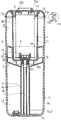
- the cartridge is formed of an enclosure whose lower part of its internal volume forms a reservoir of liquid and whose upper part of its internal volume receives the air compressor and its motor as well as the two-phase nozzle, said enclosure receiving a funnel-shaped partition wall providing a separation between the upper part and the lower part of the internal volume of said enclosure. This separation ensures a seal allowing the liquid not to flow out of the cartridge if it spills.
- the compressor and its motor are arranged in a cylindrical sleeve extending vertically in the upper part of the internal volume of the chamber and centrally with respect to the latter, said sleeve having a wall bottom and being closed at the top by a cover provided with through holes air inlet each organized baffle.
- the sheath in combination with the enclosure, delimits the expansion chamber of the aerosol, the aerosol enters the expansion chamber through the lower part of the latter, the sheath is made in a heat conducting material in order to achieve a heat exchange with the aerosol formed, the sheath, in the upper part, has a peripheral sealing collar of the upper part of the internal volume of the chamber and the chamber of relaxation, and said flange has a through bore venting the aerosol. Thanks to such an arrangement, the wall of the sheath is swept by the aerosol and heat exchange takes place between the aerosol and said wall. The heat released by both the compressor and its engine is thus communicated to the aerosol and is evacuated by the latter. Such an arrangement is conducive to facilitating the cooling of the compressor and the associated motor but also to accelerate the evaporation of the fine droplets of liquid contained in the aerosol.
- the compressed air outlet that comprises the compressor is directly connected to the compressed air inlet of the two-phase nozzle which greatly reduces the pressure drops.
- the compressor motor can then be of low electric power, in relation to the power of the compressor, which will further reduce the cost of the cartridge.
- This electric motor can then be powered with a low voltage of about four volts.
- the pressure delivered by the compressor will be of the order of 50 millibars.
- the compressor head may directly have the geometric profile of the nozzle thus making it possible to reduce the number of parts.
- the compressor head and its pump body may be an integral part of the cartridge thus making it possible to freely fix any type of electric motor.
- the suction cannula comprises at least one internal suction channel, the or each internal suction channel is equipped at the bottom with a filter and said cannula is equipped with a channel discharging liquid particles collected by a funnel-shaped partition wall towards the reservoir, which separates the upper and lower liquid-reservoir portions from the internal volume of an enclosure forming the cartridge; .
- the cannula is equipped in the lower part with a strainer means.
- the strainer means determines firstly a first internal chamber, lower in communication with the liquid reservoir and with a suction channel formed by a tube engaged in a housing of the cannula and secondly a second internal chamber, upper, in communication relation on the one hand with the exhaust duct and secondly with the first chamber through an annular through bore.
- the cannula between the housing accommodating the suction tube and the evacuation channel is provided with a longiform vertical chamber sealed at the top and open at the bottom to be in relation with one another. communication with the upper chamber of the strainer means.
- the programmed obsolescence means consist of an electronic circuit connected to the compressor motor to drive it and supply it with electrical energy.
- the electronic circuit is capable of measuring and totalizing the consumption of nebulized liquid and comparing this consumption with a reference value representative of the quantity of liquid present in the reservoir before first use, and interrupting the supply in electrical energy of the compressor motor when the setpoint is reached.
- the microcontroller is able to communicate to the electronic control board of the machine (motherboard of the housing) the data present in its memory block and in particular data relating to the end of its logged operating time.
- This communication is done on the supply son according to a protocol specific to the cartridge.
- the electronic circuit is capable of totalizing the durations of the operating cycles of the motor and comparing the value obtained with a nominal value representative of the maximum permissible duration of operation of said motor, and interrupting the supplying electrical power to said compressor motor when the setpoint is reached, this setpoint corresponds to the time required for the complete emptying of the tank.
- the value obtained by summing the durations of the previous operating cycles is representative of the quantity of liquid consumed.
- the cartridge 1 according to the invention for the production and diffusion of an aerosol, is intended to be introduced into an aerosol diffusion apparatus 2.
- Cartridge 1 comprises a closed enclosure 1a, of cylindrical shape, comprising a circular base 10 and an envelope wall 11 rooted to this bottom 10.
- the lower part of the internal volume of the chamber 1a forms a reservoir 12 designed to receive a liquid to be sprayed and is separated from the upper part of the internal volume by a partition wall 3, forming funnel around a suction cannula 4 dipping into the reservoir 12 and provided to supply liquid, a two-phase nozzle 5 for producing an aerosol, mounted in the upper part of the internal volume of the chamber 1a above the partition wall 3 and supplied with compressed air by a compressor 6, motorized also mounted with its motor 60 in the upper part of the internal volume of the chamber 1a.
- the reservoir 12 may have various capabilities. Thus the latter, by way of non-limiting example, may have capacities of 20 ml, 200 ml, 5000 ml or more.
- the partition wall 3 is provided with a cylindrical rim 30, cylindrical, upwardly whose outer diameter is equal to the internal diameter of the chamber 1a.
- the partition wall 3 is rigidly fixed, for example by ultrasonic welding, to the envelope wall 11 of the enclosure 1a.
- the compressor 6 and its motor 60 and the two-phase nozzle 5 are arranged in a cylindrical sheath 7 extending vertically in the upper part of the internal volume of the chamber 1a and centrally relative to the latter.
- This sheath 7 has a bottom wall 70 and an envelope wall 71. This sheath 7 is closed at the top by a cover 72 provided with through-holes 73, each of which is arranged in a baffle to make the introduction of foreign body in sheath 7.
- the cover 72 is provided with protruding tabs 72a provided to be clipped into indentations 71a formed in the casing wall 71 of the sheath 7, in the upper part.
- This cover 72 has vertical tabs 72c defining a wedging recess in which is introduced the upper part of the motor 60 of the compressor 6.
- the sleeve 7 in its internal volume, has several pairs of radial fins 76 each determining a wedge housing adapted to receive a radial wedge blade 62 carried by the compressor 6. In this way the compressor and motor assembly is perfectly positioned and maintained in the sleeve 7.
- the sheath 7, in the upper part, has a collar device 74 shutter of the upper part of the enclosure 1a.
- This flange 74 has a cylindrical annular retreint 74a provided to be housed in and against a form of countersink 11a formed at the upper end of the casing wall 11 and to be sealed therein, for example by ultrasonic welding.
- the sleeve 7 internally on its bottom wall 70, has a housing 75 in which is mounted the two-phase nozzle 5.
- the nozzle 5 is preferably in accordance with that described in the patent application FR 2 947 191 and is formed of a nozzle body in two upper 50 and lower 51 portions sealingly joined to each other and both delimiting a vacuum chamber 52 into which is sucked, by Venturi effect, the liquid to nebulized. More specifically, the upper part 50 of the nozzle body is provided with a through-hole 53 for introducing compressed air, in communication with the internal volume of a connection piece 50a of the part 50, in which is engaged with sealingly, a nozzle 61 of compressed air delivery that includes the compressor 6. Alternatively, the upper portion 50 is integrated with the compressor 6 and is integral with the latter.
- the lower part 51 of the nozzle body comprises at least a first through-hole 54 for feeding liquid into the vacuum chamber 52, this first through-hole opening into a vertical connecting piece 51a that comprises the lower part 51 of the nozzle body.
- This endpiece 51a is engaged in a through bore formed in the bottom wall 70 of the sheath 7 and receives the suction cannula 4 which is provided with at least one internal suction channel 4a in communication relation with the piercing. suction 54 that includes the lower portion 51 of the nozzle body.
- the tip 51a is engaged in a tubular form 70a, vertical, rooted to the bottom wall 70 and projecting therefrom.
- the lower part 51 of the nozzle body has two suction bores 54 arranged symmetrically with respect to the aerosol discharge bore, both being communication relation respectively with two end pieces 51a respectively engaged in two tubular shapes 70a.
- the suction cannula 4 comprises two suction ducts 4a in communication relation respectively with the two bores 54 and its upper end forms a fork to be connected to the two ends 51a.
- the bottom wall 70 may have a circular ring 70b, developing around and away from the cannula 4 and the bore 55 of evacuation aerosol. It may be noted that this ring penetrates into the funnel-like shape of the partition wall 3 and is located at a short distance from the upper face of the latter.
- This crown makes it possible to better filter the aerosol by trapping the large particles.
- the internal volume that this crown forms is preferably centered with respect to the piercing 55.
- the suction cannula 4 passes right through the partition wall 3 and is sealed to the latter.
- the cannula is integral with the partition wall 3.
- the cannula according to the figure 5 has two suction channels, while the cannula figures 5a and 5b has only one. Using only one cannula can limit the flow of liquid aspirated and reduce the risk of cavitation of the nozzle.
- the suction channel 4a can receive in the lower part a rigid filter 4c, ( Fig 5a ) able to retain impurities and solid dirt that might contain the liquid. This filter also has the effect of regulating the suction.
- This filter 4c is provided with a connection sleeve 4d intended to be engaged in the internal channel 4a of the cannula 4.
- the sleeve 7 is made of a material capable of conducting heat.
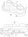
- This sleeve 7, by its lower part, is mounted in a cradle 8 carried by the partition wall 3.
- This cradle 8 ensures the holding of the sleeve 7 at a distance and above the wall of the partition 3.
- the aerosol delivered by the nozzle 5 is first introduced into the region between the cradle 8 and the wall of separation 3 and is then evacuated, by passing through through holes 80 made in the cradle 8, to an annular expansion chamber 13, formed between the upper part of the enclosure and the casing wall 71 of the sleeve 7.
- This chamber of 13 is also delimited by the cradle 8 in the lower part and by the flange 74 in the upper part.
- the flange 74 is provided with a through bore 74b.
- the aerosol is in contact with the outer face of the sheath 7 and the heat released by both the motor 60 and the compressor 6 is thus removed by the aerosol.
- Such an arrangement ensures proper cooling of the motor 60 and the compressor 6 and promotes the evaporation of the liquid droplets contained in the aerosol.
- the tightness of the sheath 7 prevents any contact between the aerosol and the compressor 6 and its motor 60.
- the sleeve 7 is firmly fixed in the chamber 1a.
- the cradle 8 comprises a tubular wall 81 by the lower edge of which it bears on the upper edge of the annular flange 30 of the partition wall 3.
- the cradle 8 further comprises at least two legs 82 holding the sheath 7, rooted by a horizontal flange that they each have the upper edge of the tubular wall 81. These tabs are angularly spaced from each other in a regular manner.
- the holes through 80 are formed in the horizontal flanges of the tabs 82.
- Each holding tab 82 has a vertical leg segment 82a extended in the lower part by a horizontal leg segment 82b of support of the sleeve 7, this segment developing so radial towards the center of the formed cradle.
- the aerosol is oriented vertically downwards and towards the separating wall 3.
- the large particles of liquid that can carry the aerosol are of a weight that is too high to be transported to the expansion chamber 13 and are deposited on the partition wall 3.
- the suction cannula 4 in the extension of a axial through hole formed in the wall 3, has a conduit 4b gravity discharge of these particles to the reservoir 12 of liquid.
- the evacuation duct 4b and the suction duct or ducts 4a that the cannula 4 has open out, at their lower end, at the lower end of the cannula, which end is supported or at a very low 12.
- Such an arrangement prevents the overturning of the capsule leading to the return of the liquid to the upper part of the cartridge 1.
- the partition wall 3 also opposes this reflux in case of overturning of the container. cartridge 1.
- FIG 5b Another embodiment of the cannula 4 is shown.
- This cannula 4 is integral with the partition wall 3, which is always in the form of a funnel.
- This cannula has only one suction channel 4a formed by a tube and a discharge channel 4b.
- the tube forming the suction channel 4a is introduced into a tubular, cylindrical, vertical housing of the cannula 4.
- this cylindrical housing comprises a constriction for receiving, without functional clearance, the upper part of the suction tube 4a .
- a seal may be arranged, in the upper part, between the housing that comprises the cannula 4 and said tube.
- an annular clearance is formed between the tube and its housing.
- the lower parts of the tube and of the cannula 4 are preferably engaged in a strainer means 40 fixed to the bottom wall of the tank 12.
- This strainer means 40 determines at least a first inner, lower chamber 41, in communication relation with the internal volume of the reservoir 12.
- This chamber is delimited by an envelope wall 42 and a horizontal upper wall 43 rooted to the envelope wall 42.
- This strainer means 40 rests on the bottom of the reservoir 12 by the lower edge of the wall envelope 42.
- the lower inner chamber 41 is in communication relation with the internal volume of the tank 12 by through holes made in particular in the envelope wall 42.
- the upper wall 43 of the strainer means 40 comprises at least one vertical connection piece 44, extending a through hole 45 formed in the upper wall 43 and opening into the first lower internal chamber 41.
- the connection piece 44 is designed to receive in The suction tube engages in the nozzle 44 and in this through bore 45 and its lower part is housed in the lower chamber 41.
- the lower part of the suction tube 4a is arranged at a short distance from the bottom of the tank 12.
- the lower chamber 41 is equipped with a filter, not shown. This filter is able to retain impurities and solid dirt that might contain the liquid to be diffused. This filter also has the effect of regulating the suction.
- connection piece 44 in combination with the upper wall 43, determines a second upper internal chamber 46.
- This upper chamber is in communication relation on the one hand with the evacuation channel 4b of the cannula and on the other part with the lower chamber 41 through an annular gap formed between the bore 45 and the suction tube 4a.
- the flows collected in the upper part by the funnel formed by the partition wall 3 can flow to the first chamber 41 and be taken up by the flow of liquid sucked.
- the small width of this annular gap limits the rise of liquid to the funnel 3 when the cartridge, inadvertently, is lying.
- the cannula comprises a longiform vertical chamber 47 sealed at the top and open at the bottom to be in communication relation with the chamber. 46.
- a chamber 47 is able to collect the liquid lifts when the cartridge is lying.
- this chamber is able to limit the rise of liquid to the funnel that forms the wall 3 and consequently, the rise of liquid towards the upper part of the cartridge.
- the evacuation duct 4b is offset laterally with respect to the center of the funnel formed by the partition wall 3.
- the cartridge 1 as described is equipped with an electronic circuit 9 able to supply and control the motor 60 of the compressor 6.
- the electronic circuit 9 is able to measure and totalize the consumption of nebulized liquid and to compare this consumption with a reference value representative of the quantity of liquid present in the tank 12 before first use, and to interrupt the 'food in electrical energy of the motor 60 of the compressor 6 when the setpoint is reached.
- the electronic circuit 9 is able to measure and totalize the durations of the operating cycles of the motor 60 and to compare the value obtained with a nominal value representative of the maximum allowable duration of operation of said motor, and interrupting the power supply of said motor 60 when the setpoint is reached, this setpoint corresponding to the time required for the complete emptying of the tank 12.
- the electronic circuit 9 is mounted wholly or partly in the sleeve 7 between the motor 60 of the compressor 6 and the cover 72.
- This cover 72 has through-holes 72b for the passage of electrical pins 93. supply of electrical energy to both the electronic circuit and the motor 60.
- These electrical pins 93 are connected to a source of electrical energy 94 external to the cartridge.
- Cartridge 1, as described, may be used such that it may be disposed in an aerosol dispensing apparatus 2.
- This apparatus 2 is preferably in the form of a housing having an internal chamber 20 in which the cartridge 1 according to the invention is removably disposed.
- This apparatus 2 is provided with a nozzle 21 for delivering the aerosol in front of which is positioned the drilling 74b that comprises the cartridge 1.
- This housing 2 is equipped with the pins 93 and the electrical energy source 94, the latter in the form of accumulators of low voltage electrical energy.
- the pins 93 are carried by the cartridge and are intended to be connected to electrical contacts carried by the device 2.
- This apparatus 2 is also equipped with an electronic circuit 100 through which the electric power source 94 supplies the pins 93.
- the circuit 9 and the electronic circuit 100 are able to exchange data via the pins 93.
- the exchanged data may relate to an identifier specific to the cartridge 1 and entered in the memory block 90 of the circuit 9 and the time of use of the cartridge. These data will be written in a memory block of the circuit 100. These arrangements will manage the cartridge change before depletion of the liquid by keeping in a memory block of the circuit 100 of the device 2 the time of use of each cartridge.
- the identifier of the cartridge will allow the device to determine if the device is compliant and can be used. If this is not the case, the power supply of the motor 60 will be prohibited by the circuit 100.
- the memory block 90 may also contain data relating to the nature of the contents of the cartridge, such as, for example, the nature of the liquid, its dates of manufacture and expiry, and other data.
- circuit 100 will communicated to circuit 100 and will be written in a memory block of the latter.
- the same device 2 can handle several cartridges 1, which can be used alternately at the discretion of the user until the liquid they contain.
Description
La présente invention est du domaine des dispositifs utilisés pour former et diffuser sous forme de micro gouttelettes, une substance liquide dans l'atmosphère d'un local à usage d'habitation ou à usage commercial et concerne plus particulièrement une cartouche de production et de diffusion d'un aérosol et un appareil la comportant, l'aérosol pouvant être formé à partir d'un parfum sous forme liquide, d'un répulsif pour animaux, sous forme liquide, d'un désinfectant sous forme liquide pour la décontamination bactériologique de l'air et des surfaces des locaux, de substances curatives sous forme liquide à visée thérapeutique, par exemple pour le traitement des voies respiratoires des malades en aérosolthérapie, ou bien à visée vétérinaire par exemple pour la vaccination des animaux d'un élevage. L'aérosol peut être formé à partir d'un combustible liquide et d'un gaz comburant en vue de l'alimentation de moteurs thermiques à source d'énergie interne aux cylindres.The present invention is in the field of devices used to form and diffuse in the form of micro droplets, a liquid substance in the atmosphere of a room for residential use or for commercial use and more particularly relates to a production and diffusion cartridge an aerosol and an apparatus comprising it, the aerosol can be formed from a perfume in liquid form, an animal repellent, in liquid form, a disinfectant in liquid form for the bacteriological decontamination of the air and surfaces of premises, healing substances in liquid form for therapeutic purposes, for example for the treatment of airways of patients in aerosoltherapy, or for veterinary purposes for example for the vaccination of animals of a farm. The aerosol can be formed from a liquid fuel and an oxidizing gas for the supply of heat engines with energy source internal to the cylinders.
On connaît de l'état de la technique divers appareils de nébulisation d'une substance liquide du type précité. Typiquement, ces appareils comprennent un réservoir prévu pour contenir la substance liquide à nébuliser, une buse de nébulisation en relation de communication avec le réservoir, apte à fractionner la substance parfumée en fines gouttelettes et la diffuser sous cette forme dans l'atmosphère et un compresseur d'air actionné par un moteur électrique apte à produire un courant d'air vecteur introduit dans la buse de nébulisation afin que la substance à nébuliser soit d'abord aspirée vers la buse par effet Venturi, ensuite fractionnée dans cette dernière et enfin propulsée vers l'extérieur toujours par le courant d'air porteur.Various devices of nebulization of a liquid substance of the aforementioned type are known from the state of the art. Typically, these devices comprise a reservoir designed to contain the liquid substance to be sprayed, a nebulization nozzle in communication relation with the reservoir, capable of splitting the perfume substance into fine droplets and diffusing it in this form into the atmosphere and a compressor. of air powered by an electric motor capable of producing a vector air stream introduced into the nebulizing nozzle so that the substance to be sprayed is first sucked towards the nozzle by Venturi effect, then fractionated in the latter and finally propelled to the outside always by the current of carrier air.
Un appareil de ce genre est notamment connu du brevet
Pour la plupart des appareils de l'art antérieur, le réservoir est amovible et une fois vide peut aisément être remplacé et rempli. L'inconvénient d'une telle disposition est que le réservoir peut être rechargé en produits liquides incompatibles avec notamment les caractéristiques de la buse qui peut se trouver encrassée ou même fortement endommagée si le produit liquide est corrosif vis-à-vis du matériau qui la compose. En outre, le réservoir, par erreur ou malveillance peut être rechargé en produits liquides incompatibles avec l'utilisation normale de l'appareil, voire en produits toxiques pour les occupants du local ou de l'habitation dans lequel ces produits doivent être diffusés.For most devices of the prior art, the tank is removable and once empty can easily be replaced and filled. The disadvantage of such an arrangement is that the reservoir can be refilled with incompatible liquid products, in particular with the characteristics of the nozzle, which can be fouled or even strongly damaged if the liquid product is corrosive with respect to the material which is compound. In addition, the tank, by mistake or maliciously can be recharged in liquid products incompatible with the normal use of the device, or even toxic products for the occupants of the room or the dwelling in which these products must be broadcast.
La présente invention a pour but de pallier les inconvénients précédemment évoqués en écartant tout risque d'erreur de nébulisation et de diffusion d'une substance impropre à l'usage envisagé et en interdisant toute utilisation ultérieure après épuisement du liquide.The present invention aims to overcome the aforementioned drawbacks by eliminating any risk of mistaking error and diffusion of a substance unsuitable for the intended use and prohibiting any subsequent use after the liquid has been used up.
Un autre but de la présente invention est une cartouche peu coûteuse à fabriquer et recyclable après usage.Another object of the present invention is an inexpensive cartridge to be manufactured and recyclable after use.
À cet effet la présente invention a pour objet une cartouche de nébulisation selon la revendication 1. Grâce à cette cartouche, on écarte tout risque de diffusion de substances impropres à l'usage envisagé et notamment de substances toxiques ou autres substances non désirées.For this purpose the present invention relates to a nebulization cartridge according to claim 1. With this cartridge, there is no risk of diffusion of substances unsuitable for the intended use and in particular of toxic substances or other unwanted substances.
Selon une autre caractéristique de l'invention, le compresseur d'air est équipé d'un moteur électrique d'actionnement et ledit compresseur avec son moteur sont disposés dans la cartouche.According to another characteristic of the invention, the air compressor is equipped with an electric actuation motor and said compressor with its motor are arranged in the cartridge.
Une telle disposition confère à la cartouche des caractéristiques de compacité et d'autonomie en termes de fonctionnement.Such an arrangement gives the cartridge characteristics of compactness and autonomy in terms of operation.
Selon une autre caractéristique de l'invention, la cartouche est formée d'une enceinte dont la partie inférieure de son volume interne forme réservoir de liquide et dont la partie supérieure de son volume interne reçoit le compresseur d'air et son moteur ainsi que la buse diphasique, ladite enceinte recevant une paroi de cloisonnement en forme d'entonnoir assurant une séparation entre la partie supérieure et la partie inférieure du volume interne de ladite enceinte. Cette séparation assure une étanchéité permettant au liquide de ne pas couler hors de la cartouche si celle-ci se renverse.According to another characteristic of the invention, the cartridge is formed of an enclosure whose lower part of its internal volume forms a reservoir of liquid and whose upper part of its internal volume receives the air compressor and its motor as well as the two-phase nozzle, said enclosure receiving a funnel-shaped partition wall providing a separation between the upper part and the lower part of the internal volume of said enclosure. This separation ensures a seal allowing the liquid not to flow out of the cartridge if it spills.
Selon une autre caractéristique de l'invention, le compresseur et son moteur sont disposés dans un fourreau cylindrique s'étendant verticalement dans la partie supérieure du volume interne de l'enceinte et de manière centrée par rapport à cette dernière, ledit fourreau présentant une paroi de fond et étant obturé en partie supérieure par un couvercle pourvu de perçages traversants d'entrée d'air organisés chacun en chicane.According to another characteristic of the invention, the compressor and its motor are arranged in a cylindrical sleeve extending vertically in the upper part of the internal volume of the chamber and centrally with respect to the latter, said sleeve having a wall bottom and being closed at the top by a cover provided with through holes air inlet each organized baffle.
Selon une autre caractéristique de l'invention, le fourreau, en combinaison avec l'enceinte, délimite la chambre de détente de l'aérosol, l'aérosol pénètre dans la chambre de détente par la partie inférieure de cette dernière, le fourreau est réalisé en une matière conductrice de la chaleur afin de réaliser un échange de chaleur avec l'aérosol formé, le fourreau, en partie supérieure, présente une collerette périphérique d'obturation de la partie supérieure du volume interne de l'enceinte et de la chambre de détente, et ladite collerette présente un perçage traversant d'évacuation de l'aérosol.
Grâce à une telle disposition, la paroi du fourreau est balayée par l'aérosol et un échange thermique s'opère entre l'aérosol et ladite paroi. La chaleur dégagée tant par le compresseur que par son moteur se trouve ainsi communiquée à l'aérosol et est évacuée par ce dernier. Une telle disposition est propice à faciliter le refroidissement du compresseur et du moteur associé mais aussi à accélérer l'évaporation des fines gouttelettes de liquide, contenues dans l'aérosol.According to another characteristic of the invention, the sheath, in combination with the enclosure, delimits the expansion chamber of the aerosol, the aerosol enters the expansion chamber through the lower part of the latter, the sheath is made in a heat conducting material in order to achieve a heat exchange with the aerosol formed, the sheath, in the upper part, has a peripheral sealing collar of the upper part of the internal volume of the chamber and the chamber of relaxation, and said flange has a through bore venting the aerosol.
Thanks to such an arrangement, the wall of the sheath is swept by the aerosol and heat exchange takes place between the aerosol and said wall. The heat released by both the compressor and its engine is thus communicated to the aerosol and is evacuated by the latter. Such an arrangement is conducive to facilitating the cooling of the compressor and the associated motor but also to accelerate the evaporation of the fine droplets of liquid contained in the aerosol.
Selon une autre caractéristique de l'invention, la sortie d'air comprimé que comporte le compresseur est directement connectée à l'entrée d'air comprimé de la buse diphasique ce qui diminue fortement les pertes de charge.According to another characteristic of the invention, the compressed air outlet that comprises the compressor is directly connected to the compressed air inlet of the two-phase nozzle which greatly reduces the pressure drops.
Une telle disposition est propice d'une part à diminuer la pression d'air nécessaire au bon fonctionnement de la buse diphasique et donc d'utiliser des compresseurs de faible puissance mécanique et par voie de conséquence peu coûteux. En outre, le moteur du compresseur pourra alors être de faible puissance électrique, en rapport avec la puissance du compresseur, ce qui diminuera encore le coût de la cartouche. Ce moteur électrique pourra alors être alimenté avec une tension faible d'environ quatre volts. La pression délivrée par le compresseur sera de l'ordre de 50 millibars.Such an arrangement is conducive on the one hand to reduce the air pressure necessary for the proper functioning of the two-phase nozzle and therefore to use compressors of low mechanical power and consequently inexpensive. In addition, the compressor motor can then be of low electric power, in relation to the power of the compressor, which will further reduce the cost of the cartridge. This electric motor can then be powered with a low voltage of about four volts. The pressure delivered by the compressor will be of the order of 50 millibars.
Selon une autre caractéristique la tête du compresseur pourra avoir directement le profil géométrique de la buse permettant ainsi de réduire le nombre de pièces.According to another characteristic, the compressor head may directly have the geometric profile of the nozzle thus making it possible to reduce the number of parts.
Selon une autre caractéristique la tête du compresseur et son corps de pompe pourront faire partie intégrante de la cartouche permettant ainsi de fixer librement n'importe quel type de moteur électrique.According to another characteristic, the compressor head and its pump body may be an integral part of the cartridge thus making it possible to freely fix any type of electric motor.
Selon une autre caractéristique de l'invention, la canule d'aspiration comporte au moins un canal interne d'aspiration, le ou chaque canal interne d'aspiration est équipé en partie inférieure d'un filtre et ladite canule est équipée d'un canal d'évacuation vers le réservoir des particules liquides recueillies par une paroi de cloisonnement, en forme d'entonnoir, laquelle assure une séparation entre la partie supérieure et la partie inférieure, formant réservoir de liquide, du volume interne d'une enceinte formant la cartouche.According to another characteristic of the invention, the suction cannula comprises at least one internal suction channel, the or each internal suction channel is equipped at the bottom with a filter and said cannula is equipped with a channel discharging liquid particles collected by a funnel-shaped partition wall towards the reservoir, which separates the upper and lower liquid-reservoir portions from the internal volume of an enclosure forming the cartridge; .
Selon une autre caractéristique de l'invention, la canule est équipée en partie inférieure d'un moyen de crépine.According to another characteristic of the invention, the cannula is equipped in the lower part with a strainer means.
Selon une autre caractéristique de l'invention, le moyen de crépine détermine d'une part une première chambre interne, inférieure en relation de communication avec le réservoir de liquide et avec un canal d'aspiration formé par un tube engagé dans un logement de la canule et d'autre part une seconde chambre interne, supérieure, en relation de communication d'une part avec le conduit d'évacuation et d'autre part avec la première chambre au travers d'un perçage traversant annulaire.According to another characteristic of the invention, the strainer means determines firstly a first internal chamber, lower in communication with the liquid reservoir and with a suction channel formed by a tube engaged in a housing of the cannula and secondly a second internal chamber, upper, in communication relation on the one hand with the exhaust duct and secondly with the first chamber through an annular through bore.
Selon une autre caractéristique de l'invention, la canule entre le logement accueillant le tube d'aspiration et le canal d'évacuation est dotée d'une chambre verticale longiforme obturée de manière étanche en partie supérieure et ouverte en partie inférieure pour être en relation de communication avec la chambre supérieure du moyen de crépine.According to another characteristic of the invention, the cannula between the housing accommodating the suction tube and the evacuation channel is provided with a longiform vertical chamber sealed at the top and open at the bottom to be in relation with one another. communication with the upper chamber of the strainer means.
Selon une autre caractéristique de l'invention, les moyens d'obsolescence programmée sont constitués par un circuit électronique connecté au moteur du compresseur pour le piloter et l'alimenter en énergie électrique.According to another characteristic of the invention, the programmed obsolescence means consist of an electronic circuit connected to the compressor motor to drive it and supply it with electrical energy.
Selon une autre caractéristique de l'invention le circuit électronique est apte à mesurer et totaliser la consommation de liquide nébulisé et comparer cette consommation à une valeur de consigne représentative de la quantité de liquide présente dans le réservoir avant premier usage, et interrompre l'alimentation en énergie électrique du moteur du compresseur lorsque la valeur de consigne est atteinte.According to another characteristic of the invention, the electronic circuit is capable of measuring and totalizing the consumption of nebulized liquid and comparing this consumption with a reference value representative of the quantity of liquid present in the reservoir before first use, and interrupting the supply in electrical energy of the compressor motor when the setpoint is reached.
Selon une autre caractéristique de l'invention, le circuit électronique intègre au moins :
- un bloc mémoire contenant une donnée relative à la quantité de liquide présente dans le réservoir avant premier usage de l'appareil, une donnée relative à la nature du liquide et une donnée relative à la viscosité du liquide à nébuliser,
- un microcontrôleur apte à calculer le débit instantané de consommation de liquide, et la quantité de liquide consommée, ledit microcontrôleur étant apte de plus à comparer la quantité consommée à la valeur de consigne,
- une interface de puissance au travers de laquelle le moteur du compresseur se trouve alimenté en énergie électrique, ladite interface de puissance étant pilotée par le microcontrôleur pour interrompre l'alimentation du moteur lorsque la valeur de consigne est atteinte.
- a memory block containing data relating to the quantity of liquid present in the tank before first use of the apparatus, data relating to the nature of the liquid and data relating to the viscosity of the liquid to be sprayed,
- a microcontroller capable of calculating the instantaneous flow rate of liquid consumption, and the quantity of liquid consumed, said microcontroller being further able to compare the quantity consumed with the desired value,
- a power interface through which the motor of the compressor is supplied with electrical energy, said power interface being controlled by the microcontroller to interrupt the supply of the motor when the set value is reached.
Le microcontrôleur est apte à communiquer à la carte électronique de pilotage de la machine (carte mère du boîtier) les données présentes dans son bloc mémoire et en particulier une donnée relative à la fin de son temps de fonctionnement consigné.The microcontroller is able to communicate to the electronic control board of the machine (motherboard of the housing) the data present in its memory block and in particular data relating to the end of its logged operating time.
Cette communication se fait sur les fils d'alimentation selon un protocole spécifique à la cartouche.This communication is done on the supply son according to a protocol specific to the cartridge.
Alternativement, selon une autre caractéristique de l'invention, le circuit électronique est apte à totaliser les durées des cycles de fonctionnement du moteur et comparer la valeur obtenue à une valeur de consigne représentative de la durée maximale autorisée de fonctionnement dudit moteur, et interrompre l'alimentation en énergie électrique dudit moteur du compresseur lorsque la valeur de consigne est atteinte, cette valeur de consigne correspond à la durée requise pour le vidage complet du réservoir. La valeur obtenue par la totalisation des durées des cycles de fonctionnement antérieurs est représentative de la quantité de liquide consommée.Alternatively, according to another characteristic of the invention, the electronic circuit is capable of totalizing the durations of the operating cycles of the motor and comparing the value obtained with a nominal value representative of the maximum permissible duration of operation of said motor, and interrupting the supplying electrical power to said compressor motor when the setpoint is reached, this setpoint corresponds to the time required for the complete emptying of the tank. The value obtained by summing the durations of the previous operating cycles is representative of the quantity of liquid consumed.
Selon une autre caractéristique de l'invention, le circuit électronique intègre au moins :
- un bloc mémoire contenant une donnée relative à la durée maximale d'utilisation du moteur du compresseur,
- un microcontrôleur apte à mesurer et totaliser les durées des cycles de fonctionnement du moteur du compresseur et comparer la valeur de cette mesure à la valeur de consigne,
- une interface de puissance au travers de laquelle le moteur du compresseur se trouve alimenté en énergie électrique, ladite interface de puissance étant pilotée par le microcontrôleur pour interrompre l'alimentation du moteur lorsque la valeur de consigne est atteinte.
- Le microcontrôleur dialogue en temps réel avec la carte-mère et maintien en mémoire le temps d'utilisation de la cartouche ceci est un avantage lorsque l'on change de cartouche en cours d'utilisation.
- Le microcontrôleur pourra aussi délivrer à la carte mère des informations sur la nature du contenu de la cartouche comme par exemple le nom du liquide, ses dates de fabrication et de péremption et autres données.
- a memory block containing data relating to the maximum duration of use of the compressor motor,
- a microcontroller capable of measuring and totalizing the durations of the operating cycles of the compressor motor and comparing the value of this measurement with the set value,
- a power interface through which the motor of the compressor is supplied with electrical energy, said power interface being controlled by the microcontroller to interrupt the supply of the motor when the set value is reached.
- The microcontroller communicates in real time with the motherboard and keeps in memory the time of use of the cartridge this is an advantage when changing cartridges in use.
- The microcontroller can also deliver to the motherboard information on the nature of the contents of the cartridge such as the name of the liquid, its dates of manufacture and expiry and other data.
D'autres avantages, buts et caractéristiques de l'invention apparaîtront à la lecture de la description d'une forme préférée de réalisation, donnée à titre d'exemple non limitatif en se référant aux dessins annexés en lesquels :
- la
figure 1 est une vue en perspective, selon une échelle agrandie, d'une cartouche conforme à l'invention, - la
figure 2 est une vue de dessus de la cartouche selon l'invention, - la
figure 3 est une vue en coupe selon la ligne AA de lafigure 2 , - la
figure 4 est une vue en médaillon montrant le détail de la buse diphasique équipant la cartouche selon l'invention, - la
figure 5 est une vue en perspective d'une paroi de cloisonnement et d'une canule d'aspiration, - la
figure 5a est une vue de face d'une variante de réalisation d'une paroi de cloisonnement avec canule d'aspiration, - la
figure 5b est une vue en coupe d'une autre variante d'exécution d'une canule avec paroi de cloisonnement, - les
figures 5c et 5d sont respectivement des vues en perspective de dessus et de dessous du moyen de crépine, - la
figure 6 est une vue en perspective d'un fourreau, - la
figure 7 est une vue en coupe longitudinale du fourreau selon lafigure 6 , - la
figure 8 est une vue en perspective de dessous du couvercle associé au fourreau, - la
figure 9 est une vue en coupe de ce couvercle, - la
figure 10 est une vue en perspective du berceau dans lequel repose le fourreau, - la
figure 11 est une vue schématique du circuit électronique, - la
figure 12 est une vue selon une échelle réduite d'un appareil de diffusion équipé d'une cartouche selon l'invention.
- the
figure 1 is a perspective view, on an enlarged scale, of a cartridge according to the invention, - the
figure 2 is a top view of the cartridge according to the invention, - the
figure 3 is a sectional view along line AA of thefigure 2 , - the
figure 4 is a medallion view showing the detail of the two-phase nozzle equipping the cartridge according to the invention, - the
figure 5 is a perspective view of a partition wall and a suction cannula, - the
figure 5a is a front view of an alternative embodiment of a partition wall with suction cannula, - the
figure 5b is a sectional view of another alternative embodiment of a cannula with partition wall, - the
Figures 5c and 5d are respectively perspective views from above and below the strainer means, - the
figure 6 is a perspective view of a sheath, - the
figure 7 is a longitudinal sectional view of the sheath according to thefigure 6 , - the
figure 8 is a perspective view from below of the cover associated with the sheath, - the
figure 9 is a sectional view of this lid, - the
figure 10 is a perspective view of the cradle in which the sheath rests, - the
figure 11 is a schematic view of the electronic circuit, - the
figure 12 is a view on a reduced scale of a diffusion apparatus equipped with a cartridge according to the invention.
Telle que représentée, la cartouche 1 selon l'invention, pour la production et diffusion d'un aérosol, est prévue pour être introduite dans un appareil de diffusion d'aérosol 2.As shown, the cartridge 1 according to the invention, for the production and diffusion of an aerosol, is intended to be introduced into an
La cartouche 1, selon l'invention, comprend une enceinte 1a close, de forme cylindrique, comportant un fond 10 circulaire et une paroi enveloppe 11 enracinée à ce fond 10.Cartridge 1, according to the invention, comprises a
La partie inférieure du volume interne de l'enceinte 1a forme un réservoir 12 prévu pour recevoir un liquide à nébuliser et est séparée de la partie supérieure du volume interne par une paroi de cloisonnement 3, formant entonnoir autour d'une canule d'aspiration 4 plongeant dans le réservoir 12 et prévue pour alimenter en liquide, une buse diphasique 5 de production d'un aérosol, montée dans la partie supérieure du volume interne de l'enceinte 1a au-dessus de la paroi de cloisonnement 3 et alimentée en air comprimé par un compresseur 6, motorisé monté également avec son moteur 60 dans la partie supérieure du volume interne de l'enceinte 1a.The lower part of the internal volume of the
Le réservoir 12 peut présenter diverses capacités. Ainsi ce dernier, à titre d'exemple non limitatif, pourra présenter des capacités de 20 ml, 200 ml, 5000 ml ou plus.The
Selon la forme préférée de réalisation, la paroi de cloisonnement 3 est dotée d'un rebord annulaire 30, cylindrique, orienté vers le haut dont le diamètre externe est égal au diamètre interne de l'enceinte 1a. Par ce rebord annulaire 30, la paroi de séparation 3 est rigidement fixée, par soudage à ultra sons par exemple, à la paroi enveloppe 11 de l'enceinte 1a.According to the preferred embodiment, the
Avantageusement, le compresseur 6 et son moteur 60 ainsi que la buse diphasique 5 sont disposés dans un fourreau cylindrique 7 s'étendant verticalement dans la partie supérieure du volume interne de l'enceinte 1a et de manière centrée par rapport à cette dernière.Advantageously, the compressor 6 and its
Ce fourreau 7 présente une paroi de fond 70 et une paroi enveloppe 71. Ce fourreau 7 est obturé en partie supérieure par un couvercle 72 pourvu de perçages traversants d'entrée d'air 73, organisés chacun en chicane pour rendre difficile l'introduction de corps étranger dans le fourreau 7.This
Selon une forme pratique de réalisation, le couvercle 72 est doté de pattes saillantes 72a prévues pour être clipsées dans des empreintes en creux 71a formées dans la paroi enveloppe 71 du fourreau 7, en partie supérieure. Ce couvercle 72 présente des pattes verticales 72c déterminant un logement de calage dans lequel est introduite la partie supérieure du moteur 60 du compresseur 6. En partie inférieure, le fourreau 7, dans son volume interne, présente plusieurs paires d'ailettes radiales 76 déterminant chacune un logement de calage prévu pour recevoir une ailette radiale de calage 62 portée par le compresseur 6. De cette manière l'ensemble compresseur et moteur se trouve parfaitement positionné et maintenu dans le fourreau 7.According to a practical embodiment, the
De préférence, le fourreau 7, en partie supérieure, présente une collerette périphérique 74 d'obturation de la partie supérieure de l'enceinte 1a. Cette collerette 74 présente un retreint annulaire cylindrique 74a prévu pour venir se loger dans et contre une forme de lamage 11a formée en extrémité supérieure de la paroi enveloppe 11 et y être fixé de manière étanche, par exemple par soudage à ultrasons.Preferably, the
Le fourreau 7, intérieurement sur sa paroi de fond 70, présente un logement 75 dans lequel est montée la buse diphasique 5.The
La buse 5 est de préférence conforme à celle décrite dans la demande de brevet
La partie inférieure 51 de corps de buse comporte au moins un premier perçage traversant 54 d'amené du liquide dans la chambre de dépression 52, ce premier perçage traversant débouchant dans un embout 51a vertical de raccordement que comporte la partie inférieure 51 du corps de buse. Cet embout 51a est engagé dans un perçage traversant pratiqué dans la paroi de fond 70 du fourreau 7 et reçoit la canule d'aspiration 4 laquelle est dotée d'au moins un canal interne d'aspiration 4a venant en relation de communication avec le perçage d'aspiration 54 que comporte la partie inférieure 51 de corps de buse.The
Selon une forme pratique de réalisation, l'embout 51a est engagé dans une forme tubulaire 70a, verticale, enracinée à la paroi de fond 70 et formant saillie sous cette dernière.According to a practical embodiment, the
La partie inférieure 51 du corps de buse, dans l'axe du perçage traversant 53 que comporte la partie supérieure 50, est dotée d'un perçage traversant 55 d'évacuation de l'aérosol, ce dit perçage étant axialement aligné avec un perçage traversant pratiqué dans la paroi de fond 70 du fourreau 7.The
De préférence, la partie inférieure 51 de corps de buse présente deux perçages d'aspiration 54 disposés de manière symétrique par rapport au perçage d'évacuation de l'aérosol, tous les deux étant relation de communication respectivement avec deux embouts 51a engagés respectivement dans deux formes tubulaires 70a. Avec une telle forme de réalisation, la canule d'aspiration 4 comporte deux conduits d'aspiration 4a en relation de communication respectivement avec les deux perçages 54 et son extrémité supérieure forme une fourche pour pouvoir être raccordée aux deux embouts 51a.Preferably, the
De façon à réduire le niveau sonore de la buse, la paroi de fond 70, en saillie sous sa face externe au fourreau, pourra présenter une couronne circulaire 70b, se développant autour et à distance de la canule 4 et du perçage 55 d'évacuation de l'aérosol. On peut remarquer que cette couronne pénètre dans la forme d'entonnoir que présente la paroi de cloisonnement 3 et se situe à faible distance de la face supérieure de cette dernière. Cette couronne permet de mieux filtrer l'aérosol en piégeant les grosses particules. Le volume interne que forme cette couronne est de préférence centré par rapport au perçage 55.In order to reduce the sound level of the nozzle, the
La canule d'aspiration 4 traverse de part en part la paroi de cloisonnement 3 et est solidarisée de manière étanche à cette dernière. De préférence, la canule fait corps avec la paroi de cloisonnement 3.The
On peut observer que la canule selon la
Le fourreau 7 est réalisé en une matière apte à conduire la chaleur. Ce fourreau 7, par sa partie inférieure, est monté dans un berceau 8 porté par la paroi de séparation 3. Ce berceau 8 assure le maintien du fourreau 7 à distance et au-dessus de la de la paroi de séparation 3. Ainsi l'aérosol délivré par la buse 5 est d'abord introduit dans la région comprise entre le berceau 8 et la paroi de séparation 3 et est ensuite évacué, par passage au travers de perçages traversants 80 pratiqués dans le berceau 8, vers une chambre de détente annulaire 13, formée entre la partie supérieure de l'enceinte et la paroi enveloppe 71 du fourreau 7. Cette chambre de détente 13 est également délimitée par le berceau 8 en partie inférieure et par la collerette 74 en partie supérieure.The
Pour permettre l'évacuation de l'aérosol vers l'extérieur depuis cette chambre de détente 13, la collerette 74 est dotée d'un perçage traversant 74b.To allow the evacuation of the aerosol to the outside from this
Grâce aux dispositions qui viennent d'être décrites, l'aérosol se trouve au contact de la face externe du fourreau 7 et la chaleur dégagée tant par le moteur 60 que par le compresseur 6 se trouve ainsi évacuée par l'aérosol. Une telle disposition assure un refroidissement correct du moteur 60 et du compresseur 6 et favorise l'évaporation des gouttelettes de liquide contenues dans l'aérosol. L'étanchéité du fourreau 7 interdit tout contact entre l'aérosol et le compresseur 6 et son moteur 60.Thanks to the arrangements just described, the aerosol is in contact with the outer face of the
Grâce au berceau 8 et à la collerette 74, le fourreau 7 est fermement maintenu fixe dans l'enceinte 1a.Thanks to the
Le berceau 8, selon une forme préférée de réalisation, comprend une paroi tubulaire 81 par la bordure inférieure de laquelle il prend appui sur la bordure supérieure du rebord annulaire 30 de la paroi de séparation 3. Le berceau 8 comprend en outre au moins deux pattes 82 de maintien du fourreau 7, enracinées par une aile horizontale qu'elles présentent chacune, à la bordure supérieure de la paroi tubulaire 81. Ces pattes sont angulairement écartées les unes des autres de manière régulière. Les perçages traversant 80 sont formés dans les ailes horizontales des pattes 82. Chaque patte de maintien 82 présente un segment vertical de patte 82a prolongé en partie inférieure par un segment de patte horizontal 82b d'appui du fourreau 7, ce segment se développant de manière radiale vers le centre du berceau formé.The
En sortie de buse 5, l'aérosol est orienté verticalement vers le bas et vers la paroi de séparation 3. Les grosses particules de liquide que peut transporter l'aérosol sont d'un poids trop élevé pour être transportées vers la chambre de détente 13 et se déposent sur la paroi de cloisonnement 3. Pour éviter tout engorgement à ce niveau, la canule d'aspiration 4, dans le prolongement d'un perçage traversant axial formé dans la paroi 3, présente un conduit 4b d'évacuation par gravité de ces particules vers le réservoir 12 de liquide. On peut remarquer que le conduit d'évacuation 4b et le ou les conduits d'aspiration 4a que comporte la canule 4 débouchent, par leur extrémité inférieure, au niveau de l'extrémité inférieure de la canule, laquelle extrémité est en appui ou à très faible distance du fond du réservoir 12. Une telle disposition évite que le renversement de la capsule conduise au refluement du liquide vers la partie supérieure de la cartouche 1. La paroi de cloisonnement 3 s'oppose aussi à ce refluement en cas de renversement de la cartouche 1.At the outlet of the
En
Les parties inférieures du tube et de la canule 4 sont préférentiellement engagées dans un moyen de crépine 40 fixé à la paroi de fond du réservoir 12. Ce moyen de crépine 40 détermine au moins une première chambre interne, inférieure 41, en relation de communication avec le volume interne du réservoir 12. Cette chambre est délimitée par une paroi enveloppe 42 et par une paroi supérieure horizontale 43 enracinée à la paroi enveloppe 42. Ce moyen de crépine 40 repose sur le fond du réservoir 12 par la bordure inférieure de la paroi enveloppe 42. La chambre interne inférieure 41 est en relation de communication avec le volume interne du réservoir 12 par des perçages traversants pratiqués notamment dans la paroi enveloppe 42.The lower parts of the tube and of the
La paroi supérieure 43 du moyen de crépine 40 comporte au moins un embout vertical 44 de raccordement, prolongeant un perçage traversant 45 pratiqué dans la paroi supérieure 43 et débouchant dans la première chambre interne inférieure 41. L'embout de raccordement 44 est prévu pour recevoir en emmanchement la partie inférieure de la canule 4. Le tube d'aspiration s'engage dans l'embout 44 et dans ce perçage traversant 45 et par sa partie inférieure est logé dans la chambre inférieure 41. La partie inférieure du tube d'aspiration 4a est disposée à faible distance du fond du réservoir 12. Avantageusement, la chambre inférieure 41 est équipée d'un filtre, non représenté. Ce filtre est apte à retenir les impuretés et salissures solides que pourrait contenir le liquide à diffuser. Ce filtre a également pour effet de réguler l'aspiration.The
L'embout de raccordement 44, en combinaison avec la paroi supérieure 43, détermine une seconde chambre interne, supérieure 46. Cette chambre supérieure est en relation de communication d'une part avec le canal d'évacuation 4b de la canule et d'autre part avec la chambre inférieure 41 au travers d'un intervalle annulaire ménagé entre la perçage 45 et le tube d'aspiration 4a. De cette manière, les écoulements recueillis en partie supérieure par l'entonnoir que forme la paroi de séparation 3 peuvent s'écouler vers la première chambre 41 et être repris par le flux de liquide aspiré. De plus la faible largeur de cet intervalle annulaire limite les remontées de liquide vers l'entonnoir 3 lorsque la cartouche, par mégarde, est couchée. Avantageusement entre le conduit d'évacuation 4b et le logement prévu pour accueillir le tube d'aspiration 4a, la canule comporte une chambre verticale longiforme 47 obturée de manière étanche en partie supérieure et ouverte en partie inférieure pour être en relation de communication avec la chambre supérieure 46. Une telle chambre 47 est apte à recueillir les remontées de liquide lorsque la cartouche est couchée. Ainsi cette chambre est apte à limiter les remontées de liquide vers l'entonnoir que forme la paroi 3 et par voie de conséquence, les remontées de liquide vers la partie supérieure de la cartouche. Avantageusement, le conduit d'évacuation 4b est décalé latéralement par rapport au centre de l'entonnoir que forme la paroi de cloisonnement 3.The
La cartouche 1 telle que décrite est dotée d'un circuit électronique 9 apte à alimenter et piloter le moteur 60 du compresseur 6.The cartridge 1 as described is equipped with an
Selon une première forme de réalisation, le circuit électronique 9 est apte à mesurer et totaliser la consommation de liquide nébulisé et à comparer cette consommation à une valeur de consigne représentative de la quantité de liquide présente dans le réservoir 12 avant premier usage, et interrompre l'alimentation en énergie électrique du moteur 60 du compresseur 6 lorsque la valeur de consigne est atteinte.According to a first embodiment, the
Selon cette forme de réalisation, le circuit électronique 9 intègre au moins :
- un bloc mémoire 90 contenant une donnée relative à la quantité de liquide présente dans le réservoir avant premier usage de l'appareil, une donnée relative à la nature du liquide et une donnée relative à la viscosité du liquide à nébuliser,
un microcontrôleur 91 apte à calculer le débit instantané de consommation de liquide, et la quantité de liquide consommée, ledit microcontrôleur étant apte de plus à comparer la quantité consommée à la valeur de consigne,- une interface de puissance 92 au travers de laquelle le moteur 60 du compresseur se trouve alimenté en énergie électrique, ladite interface de puissance 92 étant pilotée par le microcontrôleur 91 pour interrompre l'alimentation du moteur 60 lorsque la valeur de consigne est atteinte.
- a
memory block 90 containing data relating to the quantity of liquid present in the tank before first use of the apparatus, data relating to the nature of the liquid and data relating to the viscosity of the liquid to be sprayed, - a
microcontroller 91 capable of calculating the instantaneous flow rate of consumption of liquid, and the quantity of liquid consumed, the said microcontroller being further able to compare the quantity consumed with the reference value, - a
power interface 92 through which themotor 60 of the compressor is supplied with electrical energy, saidpower interface 92 being controlled by themicrocontroller 91 to interrupt the supply of themotor 60 when the set value is reached.
Selon une seconde forme de réalisation, le circuit électronique 9 est apte à mesurer et à totaliser les durées des cycles de fonctionnement du moteur 60 et à comparer la valeur obtenue à une valeur de consigne représentative de la durée maximale autorisée de fonctionnement dudit moteur, et interrompre l'alimentation en énergie électrique dudit moteur 60 lorsque la valeur de consigne est atteinte, cette valeur de consigne correspondant à la durée requise pour le vidage complet du réservoir 12.According to a second embodiment, the
Selon cette seconde forme de réalisation de l'invention, le circuit électronique intègre au moins :
- un bloc mémoire 90 contenant une donnée relative à la durée maximale d'utilisation du moteur du compresseur,
un microcontrôleur 91 apte à mesurer et totaliser les durées des cycles de fonctionnement du moteur du compresseur et comparer la valeur de cette mesure à la valeur de consigne,- une interface de puissance 92 au travers de laquelle le moteur du compresseur se trouve alimenté en énergie électrique, ladite interface de puissance étant pilotée par le microcontrôleur pour interrompre l'alimentation du moteur lorsque la valeur de consigne est atteinte.
- a
memory block 90 containing data relating to the maximum duration of use of the compressor motor, - a
microcontroller 91 able to measure and totalize the operating cycle times of the compressor motor and compare the value of this measurement with the set value, - a
power interface 92 through which the motor of the compressor is supplied with electrical energy, said power interface being controlled by the microcontroller to interrupt the power supply of the motor when the set value is reached.
Dans la forme pratique de réalisation, le circuit électronique 9 est monté en totalité ou en partie dans le fourreau 7 entre le moteur 60 du compresseur 6 et le couvercle 72. Ce couvercle 72 présente des perçages traversants 72b de passage de broches électriques 93 d'alimentation en énergie électrique tant du circuit électronique que du moteur 60. Ces broches électriques 93 sont connectées à une source d'énergie électrique 94 externe à la cartouche.In the practical embodiment, the
La cartouche 1, telle que décrite, peut être utilisée telle qu'elle ou bien être disposée dans un appareil de diffusion 2 d'un aérosol. Cet appareil 2 se présente de préférence sous la forme d'un boîtier doté d'une chambre interne 20 dans laquelle est disposée de manière amovible la cartouche 1 selon l'invention.Cartridge 1, as described, may be used such that it may be disposed in an
Cet appareil 2 est doté d'un ajutage 21 de délivrance de l'aérosol en regard duquel est positionné le perçage 74b que comporte la cartouche 1. Ce boîtier 2 est équipé des broches 93 et de la source d'énergie électrique 94, cette dernière se présentant sous la forme d'accumulateurs d'énergie électrique basse tension. Alternativement, les broches 93 sont portées par la cartouche et sont prévues pour être connectées à des contacts électriques portés par l'appareil 2.This
Cet appareil 2 est également équipé d'un circuit électronique 100 au travers duquel la source d'énergie électrique 94 alimente les broches 93. Le circuit 9 et le circuit électronique 100 sont aptes à échanger des données par l'intermédiaire des broches 93.This
Les données échangées pourront être relatives à un identifiant propre à la cartouche 1 et inscrit dans le bloc mémoire 90 du circuit 9 et au temps d'utilisation de la cartouche. Ces données seront inscrites dans un bloc mémoire du circuit 100. Ces dispositions permettront de gérer le changement de cartouche avant épuisement du liquide en conservant dans un bloc mémoire du circuit 100 de l'appareil 2 le temps d'utilisation de chaque cartouche.The exchanged data may relate to an identifier specific to the cartridge 1 and entered in the
L'identifiant de la cartouche permettra à l'appareil de déterminer si cette dernière est conforme et si elle peut être utilisée. Si tel n'est pas le cas, l'alimentation en énergie électrique du moteur 60 sera interdite par le circuit 100.The identifier of the cartridge will allow the device to determine if the device is compliant and can be used. If this is not the case, the power supply of the
Le bloc mémoire 90 pourra aussi contenir des données relatives à la nature du contenu de la cartouche comme par exemple la nature du liquide, ses dates de fabrication et de péremption ainsi que d'autres données.The
Ces diverses données seront communiquées au circuit 100 et seront inscrites dans un bloc mémoire de ce dernier.These various data will be communicated to
Grâce à ces diverses dispositions, un même appareil 2 pourra gérer plusieurs cartouches 1, lesquelles pourront être utilisées alternativement au gré de l'utilisateur jusqu'à épuisement du liquide qu'elles contiennent.Thanks to these various provisions, the
Il va de soi que la présente invention peut recevoir tous aménagements et variantes du domaine des équivalents techniques sans pour autant sortir du cadre du présent brevet tel que défini par les revendications ci-après.It goes without saying that the present invention can receive any arrangements and variants of the field of technical equivalents without departing from the scope of this patent as defined by the claims below.
Claims (15)
- A cartridge for producing and dispensing an aerosol (1) comprising a container (12) containing a liquid to be sprayed, a two-phase spraying nozzle (5) in communication with the container (12) by an inner channel (4a) of a suction cannula (4) and an air compressor (6) capable of producing a carrier stream of compressed air introduced into the two-phase nozzle (5) so that the contents of the container is first sucked in by Venturi effect, then fractionated and finally propelled first to an expansion chamber (13) and then to the outside, still by the carrier stream, characterized in that the elements of which it consists form a non-dismountable assembly and that it includes means of planned obsolescence capable of directly or indirectly determining the total quantity of liquid consumed in previous operating cycles, capable of comparing this value with a setpoint value representative of the quantity of liquid present in the container before the first use, and capable of preventing the subsequent operation of the compressor when the liquid contained in the container (12) has been drained to render said cartridge unusable even if the container of the latter is filled again.
- The cartridge according to claim 1, characterized in that the air compressor (6) is equipped with an electrical actuator motor (60) and in that said compressor with its motor are arranged in said cartridge.
- The cartridge according to claim 1 or claim 2, characterized in that it is formed from an enclosure (1a) whereof the lower part of its inner volume forms a liquid container (12) and whereof the upper part of its inner volume receives the air compressor (6) and its motor (60) as well as the two-phase spraying nozzle (5), said enclosure (1a) receiving a partition wall (3) in the shape of a funnel which ensures a separation between the upper part and the lower part of the inner volume of said enclosure (1a).
- The cartridge according to the preceding claim, characterized in that the compressor (6) and its motor (60) are arranged in a cylindrical sheath (7) extending vertically in the upper part of the inner volume of the enclosure (1a) and centered with respect to the latter, said sheath (7) having a bottom wall (70) and being closed in the upper part by a lid (72) provided with through holes (73) for letting in air, organized in a zigzag.
- The cartridge according to the preceding claim, characterized in that the sheath (7) in combination with the enclosure (1a) delimits the expansion chamber (13) of the aerosol, in that the aerosol enters the expansion chamber (13) by the lower part of the latter, in that the sheath (7) is made of a heat-conducting material in order to effect a heat exchange with the formed aerosol, in that the sheath (7), in the upper part, has a peripheral flange (74) for closing the upper part of the inner volume of the enclosure (1a) and of the expansion chamber (13), and in that said flange (74) has a through hole (74b) for evacuating the aerosol.
- The cartridge according to claim 4 or claim 5, characterized in that the sheath (7) is mounted by its lower part in a cradle (8) carried by the separating wall (3), said cradle being equipped with through holes (80) for the passage of the aerosol toward the expansion chamber (13), said sheath (7) having on the inside of its bottom wall (70) a casing (70a) wherein the two-phase nozzle (5) is mounted; the bottom wall (70) of the sheath (7) being fitted with a through hole axially aligned with the through hole (55) for evacuating the aerosol from the two-phase nozzle (5); the nozzle (5) being fitted with a through hole (53) for introducing compressed air (53) in communication with the compressed air outlet of the compressor (6) and at least one hole (54) for sucking liquid, in communication by way of the inner suction channel (4a) with the suction cannula (4), with the liquid container (12).
- The cartridge according to any one of the preceding claims, characterized in that the compressed air outlet included in the compressor (6) is directly connected to the compressed air inlet of the two-phase nozzle (5).
- The cartridge according to any one of claims 1 to 7, characterized in that the planned obsolescence means are formed by an electronic circuit (9) connected to the motor (60) of the compressor to control it and supply it with electrical energy.
- The cartridge according to the preceding claim, characterized in that the electronic circuit (9) is mounted in the sheath (7) between the motor (60) of the compressor (6) and the lid (72), that this lid (72) has through holes (72b) for running electrical pins (93) for supplying electrical energy to both the electronic circuit (9) and the motor (60) and that these electrical pins (93) are connected to a source of electrical energy (94) outside said cartridge.
- The cartridge according to claim 8 or claim 9, characterized in that the electronic circuit (9) is capable of measuring and totaling up the consumption of sprayed liquid and comparing this consumption with a setpoint value representative of the quantity of liquid present in the container (12) before the first use, and interrupting the supply of electrical energy to the motor (60) of the compressor (6) when the setpoint value has been reached.
- The cartridge according to the preceding claim, characterized in that the electronic circuit (9) incorporates at least:- a memory block (90) containing a data item relating to the quantity of liquid present in the container before the first use of the apparatus, a data item relating to the nature of the liquid and a data item relating to the viscosity of the liquid to be sprayed,- a microcontroller (91) capable of computing the instantaneous flow rate of consumption of liquid, and the quantity of liquid consumed, said microcontroller being in addition capable of comparing the consumed quantity to the setpoint value,- a power interface (92) via which the motor (60) of the compressor is supplied with electrical energy, said power interface (92) being controlled by the microcontroller (91) to interrupt the powering of the motor (60) when the setpoint value has been reached.
- The cartridge according to claim 8 or claim 9, characterized in that the electronic circuit (9) is capable of measuring and totaling the durations of the operating cycles of the motor (60) and comparing the value obtained to a setpoint value representative of the maximum authorized duration of operation of said motor, and interrupting the supply of electrical energy to said motor (60) when the setpoint value has been reached, this setpoint value corresponding to the time required for complete draining of the container (12).
- The cartridge according to the preceding claim, characterized in that the electronic circuit (9) incorporates at least:- a memory block (90) containing a data item relating to the maximum duration of use of the compressor motor,- a microcontroller (91) capable of measuring and totaling the durations of the operating cycles of the compressor motor and comparing the value of this measurement to the setpoint value,- a power interface (92), via which the compressor motor is supplied with electrical energy, said power interface being controlled by the microcontroller to interrupt the powering of the motor when the setpoint value has been reached.
- An apparatus for dispensing an aerosol, characterized in that it receives a cartridge according to any one of the preceding claims.
- The apparatus for dispensing an aerosol receiving a cartridge according to claims 5 and 9 taken together, characterized in that it is fitted with a jet (21) for delivering the aerosol facing which is positioned the hole (74b) included in the cartridge (1) and a box (1) fitted with an inner chamber (20) wherein the cartridge is removably arranged, said box being equipped with the pins (93) and the electrical energy source (94) .
Applications Claiming Priority (2)
| Application Number | Priority Date | Filing Date | Title |
|---|---|---|---|
| FR1260595A FR2997639B1 (en) | 2012-11-08 | 2012-11-08 | PROGRAMMED OBSOLESCENCE CARTRIDGE FOR PRODUCING AND DIFFUSING AEROSOL, AND DIFFUSION APPARATUS COMPRISING SAME |
| PCT/FR2013/052697 WO2014072663A1 (en) | 2012-11-08 | 2013-11-08 | Planned obsolescence cartridge, for producing and dispensing an aerosol, and spraying apparatus comprising same |
Publications (2)
| Publication Number | Publication Date |
|---|---|
| EP2916965A1 EP2916965A1 (en) | 2015-09-16 |
| EP2916965B1 true EP2916965B1 (en) | 2018-03-14 |
Family
ID=47598960
Family Applications (1)
| Application Number | Title | Priority Date | Filing Date |
|---|---|---|---|
| EP13803128.1A Active EP2916965B1 (en) | 2012-11-08 | 2013-11-08 | Planned obsolescence cartridge, for producing and dispensing an aerosol, and spraying apparatus comprising the same |
Country Status (5)
| Country | Link |
|---|---|
| US (1) | US20150290666A1 (en) |
| EP (1) | EP2916965B1 (en) |
| ES (1) | ES2672998T3 (en) |
| FR (1) | FR2997639B1 (en) |
| WO (1) | WO2014072663A1 (en) |
Families Citing this family (2)
| Publication number | Priority date | Publication date | Assignee | Title |
|---|---|---|---|---|
| US11964070B2 (en) | 2020-06-09 | 2024-04-23 | Quin Global US, Inc. | Disinfectant and sanitizer canister system and metering device for system |
| CN114602866B (en) * | 2022-03-11 | 2022-12-16 | 重庆臻宝实业有限公司 | High-pressure cleaning device and method for products with holes |
Family Cites Families (8)
| Publication number | Priority date | Publication date | Assignee | Title |
|---|---|---|---|---|
| US2249359A (en) * | 1938-07-20 | 1941-07-15 | Mfg Company Du | Insecticide spraying device |
| FR2377946A1 (en) * | 1977-01-19 | 1978-08-18 | Oreal | LIQUID PACKAGING AND DISTRIBUTION CONTAINER CONTAINING A MANUAL PUMP |
| US4941519A (en) * | 1988-08-19 | 1990-07-17 | American Sterilizer Company | Liquid feed system using a non-reusable container |
| FR2746651B1 (en) * | 1996-04-01 | 1998-04-30 | Sanitaire Equipement | AUTOMATIC INSTALLATION FOR THE SANITATION OF PREMISES AS SANITARIES |
| US6932238B2 (en) * | 2003-01-28 | 2005-08-23 | Air Liquide Advanced Technologies U.S. Llc | Non-refillable valve device |
| US20080283049A1 (en) * | 2007-02-27 | 2008-11-20 | Derek D Mahoney | High efficiency nebulizer |
| US20090050141A1 (en) * | 2007-08-21 | 2009-02-26 | Russell Wayne King | Pre-filled, single-use, disposable small volume medication nebulizer |
| FR2947191B1 (en) * | 2009-06-30 | 2012-08-24 | Klipair | DIPHASIC SPRAY NOZZLE AND NEBULIZING APPARATUS HAVING THE SAME |
-
2012
- 2012-11-08 FR FR1260595A patent/FR2997639B1/en not_active Expired - Fee Related
-
2013
- 2013-11-08 ES ES13803128.1T patent/ES2672998T3/en active Active
- 2013-11-08 US US14/440,735 patent/US20150290666A1/en not_active Abandoned
- 2013-11-08 WO PCT/FR2013/052697 patent/WO2014072663A1/en active Application Filing
- 2013-11-08 EP EP13803128.1A patent/EP2916965B1/en active Active
Also Published As
| Publication number | Publication date |
|---|---|
| FR2997639A1 (en) | 2014-05-09 |
| FR2997639B1 (en) | 2015-07-31 |
| US20150290666A1 (en) | 2015-10-15 |
| ES2672998T3 (en) | 2018-06-19 |
| WO2014072663A1 (en) | 2014-05-15 |
| EP2916965A1 (en) | 2015-09-16 |
Similar Documents
| Publication | Publication Date | Title |
|---|---|---|
| EP3729979B1 (en) | Portable water pipe | |
| FR2459052A1 (en) | INHALER WITH HOUSING PROVIDED WITH A FIXING MEANS FOR RECEIVING ALTERNATIVELY THE CHOICE OF TWO LIQUID TANKS SERVING DIFFERENT PURPOSES | |
| EP3419482B1 (en) | Apparatus for making a drink | |
| EP3580385B1 (en) | Iron including a device for retaining scale particles transported by the steam | |
| WO2013079814A1 (en) | Machine for preparing beverages by extraction from capsules | |
| EP2916965B1 (en) | Planned obsolescence cartridge, for producing and dispensing an aerosol, and spraying apparatus comprising the same | |
| EP0654635B1 (en) | Rechargeable steam generator | |
| FR3019989B1 (en) | SMOKE DIFFUSER AND ATOMIZER | |
| EP2413108B1 (en) | Metering device | |
| WO2019048797A1 (en) | Vaporizer end piece for electronic cigarettes | |
| WO2021094602A1 (en) | Nebulizing electronic cigarette | |
| EP3757279B1 (en) | Iron comprising a device for retaining scale particles carried by steam | |
| EP2139609B1 (en) | Apparatus for producing a gas charged with a volatile compound | |
| FR3026646B1 (en) | FIXED TAMIS NEBULIZATION DEVICE | |
| EP3406288B1 (en) | Gas humidifier assembly and medical ventilator with water tank having improved sealing | |
| WO2024089113A1 (en) | Atomizing electronic cigarette | |
| EP0655282A1 (en) | Apparatus for nebulizing odoriferous liquids | |
| FR3044558A1 (en) | DEVICE, CONNECTED SYSTEM, AND AROMATIC LIQUID DIFFUSION CAPSULE | |
| FR2846305A1 (en) | FLUID PRODUCT DISPENSER. | |
| CA2755261A1 (en) | Dosage device | |
| FR3110435A1 (en) | Arrangement of a breathing assistance device | |
| FR3040695A1 (en) | FLUID DISPENSING CONTAINER | |
| WO2018235051A1 (en) | Fragrance diffuser | |
| WO2007000674A1 (en) | Fountain for supplying chilled water | |
| FR3048811A1 (en) | ASPIRE WASTE TANK |
Legal Events
| Date | Code | Title | Description |
|---|---|---|---|
| PUAI | Public reference made under article 153(3) epc to a published international application that has entered the european phase |
Free format text: ORIGINAL CODE: 0009012 |
|
| 17P | Request for examination filed |
Effective date: 20150505 |
|
| AK | Designated contracting states |
Kind code of ref document: A1 Designated state(s): AL AT BE BG CH CY CZ DE DK EE ES FI FR GB GR HR HU IE IS IT LI LT LU LV MC MK MT NL NO PL PT RO RS SE SI SK SM TR |
|
| AX | Request for extension of the european patent |
Extension state: BA ME |
|
| DAX | Request for extension of the european patent (deleted) | ||
| REG | Reference to a national code |
Ref country code: DE Ref legal event code: R079 Ref document number: 602013034464 Country of ref document: DE Free format text: PREVIOUS MAIN CLASS: B05B0012020000 Ipc: B05B0007240000 |
|
| RIC1 | Information provided on ipc code assigned before grant |
Ipc: A61M 15/00 20060101ALI20170817BHEP Ipc: B05B 12/02 20060101ALI20170817BHEP Ipc: B05B 12/08 20060101ALI20170817BHEP Ipc: B05B 7/00 20060101ALI20170817BHEP Ipc: A61M 11/06 20060101ALI20170817BHEP Ipc: A01M 29/12 20110101ALI20170817BHEP Ipc: B05B 7/24 20060101AFI20170817BHEP Ipc: A61M 16/00 20060101ALN20170817BHEP Ipc: A01M 1/20 20060101ALI20170817BHEP |
|
| GRAP | Despatch of communication of intention to grant a patent |
Free format text: ORIGINAL CODE: EPIDOSNIGR1 |
|
| RIC1 | Information provided on ipc code assigned before grant |
Ipc: B05B 7/00 20060101ALI20170908BHEP Ipc: B05B 12/08 20060101ALI20170908BHEP Ipc: B05B 12/02 20060101ALI20170908BHEP Ipc: B05B 7/24 20060101AFI20170908BHEP Ipc: A61M 15/00 20060101ALI20170908BHEP Ipc: A01M 1/20 20060101ALI20170908BHEP Ipc: A61M 16/00 20060101ALN20170908BHEP Ipc: A61M 11/06 20060101ALI20170908BHEP Ipc: A01M 29/12 20110101ALI20170908BHEP |
|
| INTG | Intention to grant announced |
Effective date: 20171004 |
|
| GRAS | Grant fee paid |
Free format text: ORIGINAL CODE: EPIDOSNIGR3 |
|
| GRAA | (expected) grant |
Free format text: ORIGINAL CODE: 0009210 |
|
| AK | Designated contracting states |
Kind code of ref document: B1 Designated state(s): AL AT BE BG CH CY CZ DE DK EE ES FI FR GB GR HR HU IE IS IT LI LT LU LV MC MK MT NL NO PL PT RO RS SE SI SK SM TR |
|
| REG | Reference to a national code |
Ref country code: GB Ref legal event code: FG4D Free format text: NOT ENGLISH |
|
| REG | Reference to a national code |
Ref country code: CH Ref legal event code: EP Ref country code: AT Ref legal event code: REF Ref document number: 978328 Country of ref document: AT Kind code of ref document: T Effective date: 20180315 |
|
| REG | Reference to a national code |
Ref country code: IE Ref legal event code: FG4D Free format text: LANGUAGE OF EP DOCUMENT: FRENCH |
|
| REG | Reference to a national code |
Ref country code: DE Ref legal event code: R096 Ref document number: 602013034464 Country of ref document: DE |
|
| REG | Reference to a national code |
Ref country code: ES Ref legal event code: FG2A Ref document number: 2672998 Country of ref document: ES Kind code of ref document: T3 Effective date: 20180619 |
|
| REG | Reference to a national code |
Ref country code: NL Ref legal event code: MP Effective date: 20180314 |
|
| REG | Reference to a national code |
Ref country code: LT Ref legal event code: MG4D |
|
| PG25 | Lapsed in a contracting state [announced via postgrant information from national office to epo] |
Ref country code: FI Free format text: LAPSE BECAUSE OF FAILURE TO SUBMIT A TRANSLATION OF THE DESCRIPTION OR TO PAY THE FEE WITHIN THE PRESCRIBED TIME-LIMIT Effective date: 20180314 Ref country code: NO Free format text: LAPSE BECAUSE OF FAILURE TO SUBMIT A TRANSLATION OF THE DESCRIPTION OR TO PAY THE FEE WITHIN THE PRESCRIBED TIME-LIMIT Effective date: 20180614 Ref country code: CY Free format text: LAPSE BECAUSE OF FAILURE TO SUBMIT A TRANSLATION OF THE DESCRIPTION OR TO PAY THE FEE WITHIN THE PRESCRIBED TIME-LIMIT Effective date: 20180314 Ref country code: LT Free format text: LAPSE BECAUSE OF FAILURE TO SUBMIT A TRANSLATION OF THE DESCRIPTION OR TO PAY THE FEE WITHIN THE PRESCRIBED TIME-LIMIT Effective date: 20180314 Ref country code: HR Free format text: LAPSE BECAUSE OF FAILURE TO SUBMIT A TRANSLATION OF THE DESCRIPTION OR TO PAY THE FEE WITHIN THE PRESCRIBED TIME-LIMIT Effective date: 20180314 |
|
| REG | Reference to a national code |
Ref country code: AT Ref legal event code: MK05 Ref document number: 978328 Country of ref document: AT Kind code of ref document: T Effective date: 20180314 |
|
| PG25 | Lapsed in a contracting state [announced via postgrant information from national office to epo] |
Ref country code: GR Free format text: LAPSE BECAUSE OF FAILURE TO SUBMIT A TRANSLATION OF THE DESCRIPTION OR TO PAY THE FEE WITHIN THE PRESCRIBED TIME-LIMIT Effective date: 20180615 Ref country code: RS Free format text: LAPSE BECAUSE OF FAILURE TO SUBMIT A TRANSLATION OF THE DESCRIPTION OR TO PAY THE FEE WITHIN THE PRESCRIBED TIME-LIMIT Effective date: 20180314 Ref country code: BG Free format text: LAPSE BECAUSE OF FAILURE TO SUBMIT A TRANSLATION OF THE DESCRIPTION OR TO PAY THE FEE WITHIN THE PRESCRIBED TIME-LIMIT Effective date: 20180614 Ref country code: SE Free format text: LAPSE BECAUSE OF FAILURE TO SUBMIT A TRANSLATION OF THE DESCRIPTION OR TO PAY THE FEE WITHIN THE PRESCRIBED TIME-LIMIT Effective date: 20180314 Ref country code: LV Free format text: LAPSE BECAUSE OF FAILURE TO SUBMIT A TRANSLATION OF THE DESCRIPTION OR TO PAY THE FEE WITHIN THE PRESCRIBED TIME-LIMIT Effective date: 20180314 |
|
| PG25 | Lapsed in a contracting state [announced via postgrant information from national office to epo] |
Ref country code: MT Free format text: LAPSE BECAUSE OF FAILURE TO SUBMIT A TRANSLATION OF THE DESCRIPTION OR TO PAY THE FEE WITHIN THE PRESCRIBED TIME-LIMIT Effective date: 20180314 |
|
| PG25 | Lapsed in a contracting state [announced via postgrant information from national office to epo] |
Ref country code: NL Free format text: LAPSE BECAUSE OF FAILURE TO SUBMIT A TRANSLATION OF THE DESCRIPTION OR TO PAY THE FEE WITHIN THE PRESCRIBED TIME-LIMIT Effective date: 20180314 Ref country code: EE Free format text: LAPSE BECAUSE OF FAILURE TO SUBMIT A TRANSLATION OF THE DESCRIPTION OR TO PAY THE FEE WITHIN THE PRESCRIBED TIME-LIMIT Effective date: 20180314 Ref country code: PL Free format text: LAPSE BECAUSE OF FAILURE TO SUBMIT A TRANSLATION OF THE DESCRIPTION OR TO PAY THE FEE WITHIN THE PRESCRIBED TIME-LIMIT Effective date: 20180314 Ref country code: RO Free format text: LAPSE BECAUSE OF FAILURE TO SUBMIT A TRANSLATION OF THE DESCRIPTION OR TO PAY THE FEE WITHIN THE PRESCRIBED TIME-LIMIT Effective date: 20180314 Ref country code: IT Free format text: LAPSE BECAUSE OF FAILURE TO SUBMIT A TRANSLATION OF THE DESCRIPTION OR TO PAY THE FEE WITHIN THE PRESCRIBED TIME-LIMIT Effective date: 20180314 Ref country code: AL Free format text: LAPSE BECAUSE OF FAILURE TO SUBMIT A TRANSLATION OF THE DESCRIPTION OR TO PAY THE FEE WITHIN THE PRESCRIBED TIME-LIMIT Effective date: 20180314 |
|
| PG25 | Lapsed in a contracting state [announced via postgrant information from national office to epo] |
Ref country code: SK Free format text: LAPSE BECAUSE OF FAILURE TO SUBMIT A TRANSLATION OF THE DESCRIPTION OR TO PAY THE FEE WITHIN THE PRESCRIBED TIME-LIMIT Effective date: 20180314 Ref country code: AT Free format text: LAPSE BECAUSE OF FAILURE TO SUBMIT A TRANSLATION OF THE DESCRIPTION OR TO PAY THE FEE WITHIN THE PRESCRIBED TIME-LIMIT Effective date: 20180314 Ref country code: SM Free format text: LAPSE BECAUSE OF FAILURE TO SUBMIT A TRANSLATION OF THE DESCRIPTION OR TO PAY THE FEE WITHIN THE PRESCRIBED TIME-LIMIT Effective date: 20180314 Ref country code: CZ Free format text: LAPSE BECAUSE OF FAILURE TO SUBMIT A TRANSLATION OF THE DESCRIPTION OR TO PAY THE FEE WITHIN THE PRESCRIBED TIME-LIMIT Effective date: 20180314 |
|
| REG | Reference to a national code |
Ref country code: DE Ref legal event code: R097 Ref document number: 602013034464 Country of ref document: DE |
|
| PG25 | Lapsed in a contracting state [announced via postgrant information from national office to epo] |
Ref country code: PT Free format text: LAPSE BECAUSE OF FAILURE TO SUBMIT A TRANSLATION OF THE DESCRIPTION OR TO PAY THE FEE WITHIN THE PRESCRIBED TIME-LIMIT Effective date: 20180716 |
|
| PLBE | No opposition filed within time limit |
Free format text: ORIGINAL CODE: 0009261 |
|
| STAA | Information on the status of an ep patent application or granted ep patent |
Free format text: STATUS: NO OPPOSITION FILED WITHIN TIME LIMIT |
|
| PG25 | Lapsed in a contracting state [announced via postgrant information from national office to epo] |
Ref country code: DK Free format text: LAPSE BECAUSE OF FAILURE TO SUBMIT A TRANSLATION OF THE DESCRIPTION OR TO PAY THE FEE WITHIN THE PRESCRIBED TIME-LIMIT Effective date: 20180314 |
|
| 26N | No opposition filed |
Effective date: 20181217 |
|
| PG25 | Lapsed in a contracting state [announced via postgrant information from national office to epo] |
Ref country code: SI Free format text: LAPSE BECAUSE OF FAILURE TO SUBMIT A TRANSLATION OF THE DESCRIPTION OR TO PAY THE FEE WITHIN THE PRESCRIBED TIME-LIMIT Effective date: 20180314 |
|
| REG | Reference to a national code |
Ref country code: CH Ref legal event code: PL |
|
| PG25 | Lapsed in a contracting state [announced via postgrant information from national office to epo] |
Ref country code: LU Free format text: LAPSE BECAUSE OF NON-PAYMENT OF DUE FEES Effective date: 20181108 Ref country code: MC Free format text: LAPSE BECAUSE OF FAILURE TO SUBMIT A TRANSLATION OF THE DESCRIPTION OR TO PAY THE FEE WITHIN THE PRESCRIBED TIME-LIMIT Effective date: 20180314 |
|
| REG | Reference to a national code |
Ref country code: BE Ref legal event code: MM Effective date: 20181130 |
|
| REG | Reference to a national code |
Ref country code: IE Ref legal event code: MM4A |
|
| PG25 | Lapsed in a contracting state [announced via postgrant information from national office to epo] |
Ref country code: LI Free format text: LAPSE BECAUSE OF NON-PAYMENT OF DUE FEES Effective date: 20181130 Ref country code: CH Free format text: LAPSE BECAUSE OF NON-PAYMENT OF DUE FEES Effective date: 20181130 |
|
| PG25 | Lapsed in a contracting state [announced via postgrant information from national office to epo] |
Ref country code: IE Free format text: LAPSE BECAUSE OF NON-PAYMENT OF DUE FEES Effective date: 20181108 |
|
| PG25 | Lapsed in a contracting state [announced via postgrant information from national office to epo] |
Ref country code: BE Free format text: LAPSE BECAUSE OF NON-PAYMENT OF DUE FEES Effective date: 20181130 |
|
| PG25 | Lapsed in a contracting state [announced via postgrant information from national office to epo] |
Ref country code: TR Free format text: LAPSE BECAUSE OF FAILURE TO SUBMIT A TRANSLATION OF THE DESCRIPTION OR TO PAY THE FEE WITHIN THE PRESCRIBED TIME-LIMIT Effective date: 20180314 |
|
| PG25 | Lapsed in a contracting state [announced via postgrant information from national office to epo] |
Ref country code: HU Free format text: LAPSE BECAUSE OF FAILURE TO SUBMIT A TRANSLATION OF THE DESCRIPTION OR TO PAY THE FEE WITHIN THE PRESCRIBED TIME-LIMIT; INVALID AB INITIO Effective date: 20131108 Ref country code: MK Free format text: LAPSE BECAUSE OF NON-PAYMENT OF DUE FEES Effective date: 20180314 |
|
| PG25 | Lapsed in a contracting state [announced via postgrant information from national office to epo] |
Ref country code: IS Free format text: LAPSE BECAUSE OF FAILURE TO SUBMIT A TRANSLATION OF THE DESCRIPTION OR TO PAY THE FEE WITHIN THE PRESCRIBED TIME-LIMIT Effective date: 20180714 |
|
| PGFP | Annual fee paid to national office [announced via postgrant information from national office to epo] |
Ref country code: GB Payment date: 20221223 Year of fee payment: 10 Ref country code: FR Payment date: 20221222 Year of fee payment: 10 Ref country code: DE Payment date: 20221213 Year of fee payment: 10 |
|
| PGFP | Annual fee paid to national office [announced via postgrant information from national office to epo] |
Ref country code: ES Payment date: 20230125 Year of fee payment: 10 |