EP0654635B1 - Rechargeable steam generator - Google Patents
Rechargeable steam generator Download PDFInfo
- Publication number
- EP0654635B1 EP0654635B1 EP94402422A EP94402422A EP0654635B1 EP 0654635 B1 EP0654635 B1 EP 0654635B1 EP 94402422 A EP94402422 A EP 94402422A EP 94402422 A EP94402422 A EP 94402422A EP 0654635 B1 EP0654635 B1 EP 0654635B1
- Authority
- EP
- European Patent Office
- Prior art keywords
- cassette
- steam
- water
- porous material
- removable
- Prior art date
- Legal status (The legal status is an assumption and is not a legal conclusion. Google has not performed a legal analysis and makes no representation as to the accuracy of the status listed.)
- Expired - Lifetime
Links
Images


Classifications
-
- F—MECHANICAL ENGINEERING; LIGHTING; HEATING; WEAPONS; BLASTING
- F22—STEAM GENERATION
- F22B—METHODS OF STEAM GENERATION; STEAM BOILERS
- F22B1/00—Methods of steam generation characterised by form of heating method
- F22B1/28—Methods of steam generation characterised by form of heating method in boilers heated electrically
- F22B1/284—Methods of steam generation characterised by form of heating method in boilers heated electrically with water in reservoirs
- F22B1/285—Methods of steam generation characterised by form of heating method in boilers heated electrically with water in reservoirs the water being fed by a pump to the reservoirs
Definitions
- the present invention relates to a steam generator as defined in the preamble of claim 1.
- a steam generator conventionally consists of a water tank comprising a filling duct and communicating with a distribution by a water injection device, this chamber comprising an orifice outlet for the evaporation of the steam created by heating the water in the tank.
- the present invention aims to overcome the aforementioned drawbacks, that is to say to offer a generator that does not require monitoring or maintenance individuals or specific water treatment.
- Another object of the invention is to produce a steam generator that is simple to use, reliable and inexpensive.
- a steam generator comprising a envelope in which a porous material and a heating element are contained passing through this porous material, the envelope itself being arranged in a enclosure connected in operation to water supply means, means for controlling the heating element and the means for withdrawing steam created by heating the water introduced into the enclosure, the enclosure constituting a removable waterproof cassette connected by clips allowing connection and a quick disconnection to a fixed part of the generator containing said means of water supply, said means for controlling the heating element and said vapor withdrawal means.
- the water supply means may include an external reservoir and a pump placed between this reservoir and a water supply orifice and allowing selective introduction of water into the generator.
- the water pumped from the reservoir is introduced into a upper part of the cassette via a spray bar.
- this pump / tank assembly allows a supply generator, the tank can be filled at any time without any capacity limitation.
- the water being introduced by the pump at a pressure higher than the internal pressure of the generator it is easy to direct it to a place where its transformation into vapor is the most efficient or even where scaling can be done simply.
- the water supply means may also include manual filling means comprising a siphon to limit the height of the cassette filling with water, these means of filling being provided with means for cutting off the heating and the power supply in water controlled from the rotation of a filling plug placed in entry of these filling means.
- This automatic shutdown ensures maximum safety during filling avoiding any production of steam during this.
- This generator also comprises means for regulating the vapor in cassette outlet for continuous steam production.
- Control light or sound indicators allow control constant water level, flatness and scaling of the cassette, the latter control being obtained by a device for measuring the conductivity of the water before evaporation which is connected to the cassette.
- the present invention also relates to a removable steam cassette intended to be implemented with the preceding steam generator.
- She includes a sealed external enclosure, a water inlet orifice distributing this water to an envelope internal containing a water heating element around which is compressed a first porous material, this envelope comprising over its entire surface orifices for the evacuation of the steam produced by the heating element and the steam being expelled from the cassette through a steam outlet and the cassette removable being fitted with clips to allow connection and quick disconnection of the box constituting the external enclosure of the cassette by relative to the fixed part of the steam generator.
- the cassette comprises further a second porous material separated from the first surrounding porous material the heating element by a wall extending between two opposite edges of the cassette leaving a free space for the passage of steam, the second material porous which constitutes a trap for limestone being soaked directly by water pumped from the tank through a sprayer boom.
- the wall has connecting holes between the evaporation zone containing the first porous material and the water supply zone containing the second porous material, in order to allow irrigation of the first porous material from partially water descaled having passed through the second porous material.
- the first porous material and the heating element are integrated in a ring, advantageously made of plastic, concentric with the external enclosure of the cassette and providing in its center a free cylinder in which engages up to about half of its height a steam outlet tube secured to this enclosure external circular.
- this envelope is formed of two half-housings separable with honeycombed upper and lower faces, to ensure a easy replacement of the porous material or the heating element (e.g. heating resistance, ceramic resistance or electrodes).
- the heating element e.g. heating resistance, ceramic resistance or electrodes.
- the heating element water consists of a ceramic resistor inserted in the center of an element diffuser made of a heat conducting material, the first material porous being engaged under pressure between at least three fins of this diffuser and held in place by the perforated internal envelope.
- High and low water level detection means intended to cooperate with means for controlling these levels present in the fixed part of the generator allow constant monitoring of the proper functioning of exchanges of existing heat at the cassette.
- the detection means further include a set of electrical contacts comprising on the one hand the shielding of the heating element and on the other hand a metal strip applied against the internal part of the external enclosure of the cassette.
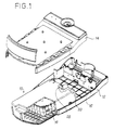
- FIG. 1 is a general view of a steam generator according to the invention.
- This generator comprises a housing assembly provided with a housing upper 14 and a lower housing 12 and inside which can be placed a Steam cassette 10.
- This connectable and disconnectable cassette by the user is connected to the upper and lower housings 14, 12 by clamps 20 having a classic structure of "clips" and allowing a quick extraction to proceed to the loading / unloading the cassette.
- the lower case 12 has a connection plate 16 on which comes into contact with the rear face of the cassette 10 in order to ensure the connections electrical and mechanical between this cassette and the generator body.
- the cassette 10 is in the form of a parallelepiped enclosure waterproof, without this particular form being limiting (it will be described later an example of a circular section cassette), inside which is fixed a envelope 18, the structure of which will be better detailed with reference to FIG. 2.
- the cassette 10 has on its internal surface ribs on which rests the envelope and which, by the difference in size of some of them, in maintain.
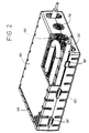
- FIG. 2 shows more precisely the structure of the envelope 18 which is present in the form of a parallelepiped made up of two half-housings, one upper 180 and the other lower 182, interconnected by fastening means 184, 186 arranged on each of these two half-housings, in order to facilitate the disassembly.
- the upper and lower faces of this parallelepiped are honeycombed a multitude of orifices 188.
- the envelope is filled with a porous material 190 surrounding an element heater, for example a heater resistor 192 (but electrodes or a ceramic resistance for example can also be used), this envelope intended to maintain the porous material geometrically with respect to water and keep its compression around the heating element.
- an element heater for example a heater resistor 192 (but electrodes or a ceramic resistance for example can also be used)
- this envelope intended to maintain the porous material geometrically with respect to water and keep its compression around the heating element.
- An intake port water 194 is practiced at the end of this envelope, the vapor produced by the water heating by the heating element escaping through the different alveoli 188.
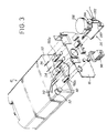
- FIG. 3 shows in detail the connections made between the cassette 10 and the connection plate 16 of the generator housing.
- the fixing means 20 of this cassette to the upper housing 14 of the generator (a similar means is present on the face bottom of the cassette to ensure a connection with the bottom box) or the heating resistance of the envelope which can consist of two resistors in series 192a, 192b and which emerges from the cassette by its rear face 22, to ensure its electrical connection with the connection plate 16.
- a conduit 24 fixed at the level of the inlet orifice 194 of the envelope also emerges from this rear face and crosses the connection plate 16 in order to be fixed tightly (this tightness being guaranteed by the use of an O-ring for example) on a water supply nozzle 26.
- sealing means 28 of the water intake orifice 194 (see figure 1) which are activated when the internal pressure of the cassette is lower than a specified pressure, eliminating the risk of vapor rejection through the water intake port.
- a steam outlet orifice 30 is made. also on the rear side of the cassette for steam evacuation escaping through the cells 188 of the envelope 18 contained in this cassette.
- Notches, for example 32 and 34, made in the body of the cassette allow to receive electrical contacts or electrodes allowing various detections.
- a detection of the water level, high and low allowing to check an overflow or a lack of water in the cassette can be implemented.
- a detection of the horizontality of this cassette can also be carried out. Electrodes intended for measuring the conductivity of water before evaporation must also be provided to allow a change of the porous material when it becomes scaled by the presence of limestone or non-mineral too much soluble.
- Steam regulation means 36 at the outlet of the cassette are provided in order to limit the vapor volume created and to obtain a continuous emission of steam.
- These means include a solenoid valve and a pressure switch whose pressure setting (steam pressure produced) is preferably chosen to be less than 0.5 bar.
- the diameter of the steam outlet conduits will be adapted in consequence to limit the pressure losses.
- the nozzle 26 has a siphon portion 260 to limit the height of the cassette water filling.
- a contactor 262 placed on this nozzle activates the electrodes for measuring the water level during filling.
- These filling means 26 also include means for cut off the water supply, for example a cam contact 264, controlled from the rotation of a water filling cap 266 placed at the inlet of these filling means and thus prohibiting any production of steam.
- the operation of the generator according to the invention is particularly simple.
- the water being introduced into the generator through the nozzle 26 (the plug of filling having of course been previously removed, this withdrawal causing a cut automatic heating), this gradually fills the envelope.
- the different electrodes make it possible to ensure the proper functioning of this filling and signal the moment of its stop to an electronic control unit 40 (see figure 4).
- the cap can therefore be closed again, the generator being ready for use.
- Activation of the heating resistance produces steam which escaping through the cells of the envelope emerges from the cassette by the steam outlet orifice to be distributed (after regulation) to the zone (s) use of this steam.
- Light or sound indicators 420, 410 are designed to alert the user to the need for water level monitoring reload the cassette with water. A check of the flatness (horizontality) of the cassette is also performed.
- the water supply to this cassette is carried out by a pump from a water tank outside the generator.
- FIG. 5 shows another embodiment of a generator.
- steam according to the invention supplied by a pump-reservoir assembly.
- the reservoir 60 has cold water and can be filled at any time without any capacity limitation. It can be removable or not.
- a pump 50 serving as a valve and preventing any return of hot water to the tank.
- This pump allows to introduce a minimum of water in the generator to keep it running knowing that the less there is faster water production is steam.
- the generator will include adequate detection devices, in particular level detection of water inside the generator, to determine the instants of control of the pump.
- the pump can be controlled to fill the lower part of the cassette 10 and thus soak the lower part of the porous material (the capillary body 190) which is heated by the resistor heating 192, the water being transformed from droplets within the capillary body in steam which escapes through the steam outlet orifice 30.
- the direct arrival of water above this porous material for example by means a spray bar 19 arranged above the casing 18 of the cassette 10 and connected to the water inlet duct 24.
- the lower part of the cassette which provides volume scaling of the body capillary pressed around the heating resistor, this supply from above essentially causes scaling on the upper part of this porous body.
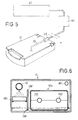
- FIG. 6 shows an example of a cassette using two porous bodies 18a, 18b, one of which is directly soaked with water from a spraying boom constitutes a limestone trap.
- This ramp 19 brings the water pumped from the reservoir into an area comprising the second porous material 18b and separated from the area evaporator comprising the first porous material 18a surrounding the resistance heater 192 by a wall 196 extending between two opposite edges of this cassette leaving a free space for the passage of steam from the contiguous evaporation zone.
- Cold water from the tank is sprayed onto the upper part of the second material and creates there, due to the heat released by the vapor produced in the evaporation zone, precipitation of salts and in particular tartar.
- the partially descaled water will pass through the body porous 18b and come to settle on the bottom of the cassette from where it will irrigate, at through connecting holes 198 drilled in the wall 196, the first porous body 18a housed in the evaporation zone from where the steam escapes through the outlet steam 30.
- FIG. 7 is another embodiment of the cassette 10 which has a cylindrical shape.
- the porous body 190 and the resistance 192 are integrated in a ring 200, advantageously in material plastic, concentric with the outer casing of the cassette and sparing in its centers a free cylinder in which engages up to about half of its height a vapor outlet tube 202 secured to this outer casing.
- the volume of water injected by the pump and resting at the bottom of the cassette is determined to avoid a flow through the steam outlet tube during a reversal of this cassette. This volume (i.e.
- the level of water in the envelope can be controlled by means of a set of electrical contacts comprising by example the shielding of resistors 192 and a metal strip 204 applied against the internal part of the envelope 10.
- the envelope can be mounted in two separable parts to facilitate maintenance, i.e. changing the element of heating or porous material.
- FIG. 8 a particular embodiment of the cassette 10 is illustrated.
- a resistance preferably of ceramic type 210, inserted, by crimping or fitting for example, in the center of a diffuser 212 produced in a heat conductive material such as aluminum for example and provided at least three fins 214a to 214d placed on either side of its center.
- a porous body 216 is inserted under pressure (compressed) between each fin and held in place by a perforated circular envelope 218 advantageously consisting of a simple grid.
- Figure 9 attempts to illustrate very schematically a method allowing a soiling of a cassette to allow its reuse.
- pumping means for example the water supply pump 50
- a water tank for example the external tank 60
- the pump draws water from the tank and enters it into the cassette where it is heated to a determined temperature below its evaporation value but above 60 ° C, to retain tartar and insoluble minerals.
- the water can then be extracted through the steam outlet 30.
Landscapes
- Engineering & Computer Science (AREA)
- Mechanical Engineering (AREA)
- Sustainable Development (AREA)
- Sustainable Energy (AREA)
- Physics & Mathematics (AREA)
- Thermal Sciences (AREA)
- Life Sciences & Earth Sciences (AREA)
- General Engineering & Computer Science (AREA)
- Engine Equipment That Uses Special Cycles (AREA)
- Thermotherapy And Cooling Therapy Devices (AREA)
- Devices For Medical Bathing And Washing (AREA)
- Air Humidification (AREA)
- Finger-Pressure Massage (AREA)
- Resistance Heating (AREA)
- Apparatus For Disinfection Or Sterilisation (AREA)
Abstract
Description
La présente invention concerne un générateur de vapeur tel que défini dans la préambule de la revendication 1.The present invention relates to a steam generator as defined in the preamble of claim 1.
Un générateur de vapeur est constitué classiquement d'un réservoir d'eau comportant un conduit de remplissage et communiquant avec une chambre de répartition par un dispositif d'injection d'eau, cette chambre comportant un orifice de sortie pour l'évaporation de la vapeur créée par le chauffage de l'eau du réservoir.A steam generator conventionally consists of a water tank comprising a filling duct and communicating with a distribution by a water injection device, this chamber comprising an orifice outlet for the evaporation of the steam created by heating the water in the tank.
Il est connu que la durée de vie de ces appareils à vapeur est limitée par la formation de tartre résultant de la vaporisation de l'eau du réservoir et accumulée au niveau des orifices d'entrée et de sortie de la chambre de vaporisation. Cette durée de vie est d'autant plus faible que l'eau utilisée présente un taux élevé de calcaire.It is known that the life of these steam devices is limited by the scale formation resulting from the vaporization of accumulated tank water at the inlet and outlet ports of the vaporization chamber. This service life is all the shorter as the water used has a high rate of limestone.
Les solutions actuelles à ce problème posé par l'entartrage des générateurs de vapeur sont multiples mais aucunement satisfaisantes: le prétraitement de l'eau ou l'utilisation d'eau déminéralisée est coûteuse et, dans ce second cas, elle nécessite parfois le recours à des matériaux spéciaux; le rinçage régulier de l'appareil constitue une contrainte mal adaptée à une utilisation professionnelle; la destruction du tartre en créant des passages entre le réservoir et la zone d'évaporation nécessite l'emploi de dispositifs mécaniques complexes tels que des tiges antitartres; de même, la détection de l'entartrage par une mesure de la pression du fluide circulant dans le générateur nécessite l'utilisation de capteurs dont la surveillance doit être constante.Current solutions to this problem posed by scaling of generators are multiple but not at all satisfactory: the water pretreatment or the use of demineralized water is expensive and, in this second case, it sometimes requires the use of special materials; regular rinsing of the device constitutes a constraint ill-suited to professional use; the destruction of scale by creating passages between the tank and the area evaporation requires the use of complex mechanical devices such as anti-scale rods; similarly, the detection of scaling by measuring the pressure of the fluid circulating in the generator requires the use of sensors whose surveillance must be constant.
On connaít par ailleurs par le document EP-A-0 317 444 un générateur de vapeur comportant une enceinte contenant un liquide à vaporiser et, à l'intérieur de cette enceinte, un bloc de vaporisation rapide comprenant au moins une résistance électrique chauffante logée dans un corps poreux qui plonge dans le liquide et est enserré dans une enveloppe ajourée. Toutefois, un tel générateur de vapeur n'optimise pas les opérations de maintenance.We also know from EP-A-0 317 444 a generator vapor comprising an enclosure containing a liquid to be vaporized and, inside this enclosure, a rapid vaporization block comprising at least one resistance electric heater housed in a porous body which dips into the liquid and is enclosed in an openwork envelope. However, such a steam generator does not optimize maintenance operations.
La présente invention a pour but de pallier les inconvénients précités, c'est-à-dire de proposer un générateur ne nécessitant ni surveillance ou entretien particuliers ni traitement spécifique de l'eau. Un autre but de l'invention est de réaliser un générateur de vapeur simple de mise en oeuvre, fiable et peu coûteux.The present invention aims to overcome the aforementioned drawbacks, that is to say to offer a generator that does not require monitoring or maintenance individuals or specific water treatment. Another object of the invention is to produce a steam generator that is simple to use, reliable and inexpensive.
Ces buts sont atteints par un générateur de vapeur comportant une enveloppe dans laquelle sont contenus un matériau poreux et un élément chauffant traversant ce matériau poreux, l'enveloppe étant elle-même disposée dans une enceinte reliée en fonctionnement à des moyens d'alimentation en eau, des moyens de commande de l'élément chauffant et des moyens de prélèvement de la vapeur créée par le chauffage de l'eau introduite dans l'enceinte, l'enceinte constituant une cassette étanche amovible reliée au moyen de pinces permettant une connexion et une déconnexion rapides à une partie fixe du générateur contenant lesdits moyens d'alimentation en eau, lesdits moyens de commande de l'élément chauffant et lesdits moyens de prélèvement de la vapeur.These aims are achieved by a steam generator comprising a envelope in which a porous material and a heating element are contained passing through this porous material, the envelope itself being arranged in a enclosure connected in operation to water supply means, means for controlling the heating element and the means for withdrawing steam created by heating the water introduced into the enclosure, the enclosure constituting a removable waterproof cassette connected by clips allowing connection and a quick disconnection to a fixed part of the generator containing said means of water supply, said means for controlling the heating element and said vapor withdrawal means.
La séparation dans une cassette des éléments de génération de la vapeur des autres constituants du générateur permet de réaliser un appareil particulièrement économique dans la mesure où le coût de cette cassette est réduit (elle comporte peu d'éléments) et sa fiabilité très grande (ces éléments sont simples).The separation in a cassette of the elements for generating steam from other components of the generator makes it possible to produce a device particularly economical insofar as the cost of this cassette is reduced (it comprises few elements) and its very high reliability (these elements are simple).
Dans un premier mode de réalisation, les moyens d'alimentation en eau peuvent comporter un réservoir externe et une pompe placée entre ce réservoir et un orifice d'alimentation en eau et permettant une introduction sélective d'eau dans le générateur. De préférence, l'eau pompée du réservoir est introduite dans une partie supérieure de la cassette par l'intermédiaire d'une rampe d'arrosage.In a first embodiment, the water supply means may include an external reservoir and a pump placed between this reservoir and a water supply orifice and allowing selective introduction of water into the generator. Preferably, the water pumped from the reservoir is introduced into a upper part of the cassette via a spray bar.
L'emploi de cet ensemble pompe/réservoir permet une alimentation continue du générateur, le réservoir pouvant être rempli à tout moment sans aucune limitation de capacité. En outre, l'eau étant introduite par la pompe à une pression supérieure à la pression interne du générateur, il est aisé de la diriger en un endroit où sa transformation en vapeur est la plus efficace voire où le détartrage peut être effectué simplement.The use of this pump / tank assembly allows a supply generator, the tank can be filled at any time without any capacity limitation. In addition, the water being introduced by the pump at a pressure higher than the internal pressure of the generator, it is easy to direct it to a place where its transformation into vapor is the most efficient or even where scaling can be done simply.
Dans un second mode de réalisation, les moyens d'alimentation en eau peuvent aussi comprendre des moyens de remplissage manuel comportant un siphon pour limiter la hauteur du remplissage en eau de la cassette, ces moyens de remplissage étant munis de moyens de coupure du chauffage et de l'alimentation en eau commandés à partir de la rotation d'un bouchon de remplissage placé en entrée de ces moyens de remplissage.In a second embodiment, the water supply means may also include manual filling means comprising a siphon to limit the height of the cassette filling with water, these means of filling being provided with means for cutting off the heating and the power supply in water controlled from the rotation of a filling plug placed in entry of these filling means.
Cette coupure automatique assure une sécurité maximale pendant le remplissage en évitant toute production de vapeur pendant celui-ci.This automatic shutdown ensures maximum safety during filling avoiding any production of steam during this.
Ce générateur comporte en outre des moyens de régulation de la vapeur en sortie de la cassette permettant d'assurer une production continue de vapeur.This generator also comprises means for regulating the vapor in cassette outlet for continuous steam production.
Des indicateurs lumineux ou sonores de contrôle permettent un contrôle constant du niveau d'eau, de la planéité et de l'entartrage de la cassette, ce dernier contrôle étant obtenu par un dispositif de mesure de la conductivité de l'eau avant évaporation qui est relié à la cassette. Control light or sound indicators allow control constant water level, flatness and scaling of the cassette, the latter control being obtained by a device for measuring the conductivity of the water before evaporation which is connected to the cassette.
La présente invention se rapporte aussi à une cassette vapeur amovible destinée à être mise en oeuvre avec le générateur de vapeur précédent. Elle comporte une enceinte externe étanche, un orifice d'admission de l'eau distribuant cette eau à une enveloppe interne contenant un élément de chauffage de l'eau autour duquel est comprimé un premier matériau poreux, cette enveloppe comportant sur toute sa surface des orifices pour l'évacuation de la vapeur produite par l'élément de chauffage et la vapeur étant expulsée de la cassette par un orifice de sortie vapeur et la cassette amovible étant équipée de pinces pour permettre une connexion et une déconnexion rapides du boítier constituant l'enceinte externe de la cassette par rapport à la partie fixe du générateur de vapeur.The present invention also relates to a removable steam cassette intended to be implemented with the preceding steam generator. She includes a sealed external enclosure, a water inlet orifice distributing this water to an envelope internal containing a water heating element around which is compressed a first porous material, this envelope comprising over its entire surface orifices for the evacuation of the steam produced by the heating element and the steam being expelled from the cassette through a steam outlet and the cassette removable being fitted with clips to allow connection and quick disconnection of the box constituting the external enclosure of the cassette by relative to the fixed part of the steam generator.
Afin d'éviter tout reflux de vapeur par l'orifice d'admission d'eau, des moyens d'obturation de l'orifice d'admission d'eau activés lorsque la pression interne de la cassette est inférieure à une pression déterminée sont prévus dans cette cassette.In order to avoid any backflow of vapor from the water inlet, means for closing the water inlet orifice activated when the pressure internal of the cassette is less than a determined pressure are provided in this cassette.
Dans une première variante de réalisation de la cassette, celle-ci comporte en outre un second matériau poreux séparé du premier matériau poreux entourant l'élément de chauffage par une paroi s'étendant entre deux bords opposés de la cassette en laissant un espace libre pour le passage de la vapeur, le second matériau poreux qui constitue un piège pour le calcaire étant imbibé directement par l'eau pompée du réservoir au travers d'une rampe d'arrosage. La paroi comporte des orifices de liaison entre la zone d'évaporation contenant le premier matériau poreux et la zone d'alimentation en eau contenant le second matériau poreux, afin de permettre une irrigation du premier matériau poreux à partir de l'eau partiellement détartrée ayant traversé le second matériau poreux.In a first variant embodiment of the cassette, it comprises further a second porous material separated from the first surrounding porous material the heating element by a wall extending between two opposite edges of the cassette leaving a free space for the passage of steam, the second material porous which constitutes a trap for limestone being soaked directly by water pumped from the tank through a sprayer boom. The wall has connecting holes between the evaporation zone containing the first porous material and the water supply zone containing the second porous material, in order to allow irrigation of the first porous material from partially water descaled having passed through the second porous material.
Dans une deuxième variante de réalisation de la cassette, le premier matériau poreux et l'élément de chauffage sont intégrés dans un anneau, avantageusement en matière plastique, concentrique à l'enceinte externe de la cassette et ménageant en son centre un cylindre libre dans lequel s'engage jusqu'à environ la moitié de sa hauteur un tube de sortie vapeur solidarisé à cette enceinte externe circulaire.In a second variant embodiment of the cassette, the first porous material and the heating element are integrated in a ring, advantageously made of plastic, concentric with the external enclosure of the cassette and providing in its center a free cylinder in which engages up to about half of its height a steam outlet tube secured to this enclosure external circular.
Avec cette structure circulaire, il est possible d'obtenir un générateur qui est capable de fournir de la vapeur dans toutes les directions de l'espace.With this circular structure, it is possible to obtain a generator which is capable of supplying steam in all directions of space.
De préférence, cette enveloppe est formée de deux demi-boítiers séparables comportant des faces supérieure et inférieure alvéolées, afin d'assurer un remplacement aisé du matériau poreux ou de l'élément chauffant (par exemple une résistance chauffante, une résistance céramique ou des électrodes). Preferably, this envelope is formed of two half-housings separable with honeycombed upper and lower faces, to ensure a easy replacement of the porous material or the heating element (e.g. heating resistance, ceramic resistance or electrodes).
Dans un troisième mode de réalisation de la cassette, l'élément de chauffage de l'eau est constitué d'une résistance céramique insérée au centre d'un élément diffuseur réalisé en un matériau conducteur de la chaleur, le premier matériau poreux étant engagé sous pression entre au moins trois ailettes de ce diffuseur et maintenu en place par l'enveloppe interne perforée.In a third embodiment of the cassette, the heating element water consists of a ceramic resistor inserted in the center of an element diffuser made of a heat conducting material, the first material porous being engaged under pressure between at least three fins of this diffuser and held in place by the perforated internal envelope.
Des moyens de détection des niveaux d'eau haut et bas destinés à coopérer avec des moyens de contrôle de ces niveaux présents dans la partie fixe du générateur permettent un suivi constant du bon fonctionnement des échanges de chaleur existant au niveau de la cassette.High and low water level detection means intended to cooperate with means for controlling these levels present in the fixed part of the generator allow constant monitoring of the proper functioning of exchanges of existing heat at the cassette.
Pour déterminer la présence d'un niveau d'eau déterminé dans l'enceinte, les moyens de détection comportent en outre un jeu de contacts électriques comprenant d'une part le blindage de l'élément de chauffage et d'autre part une bande métallique appliquée contre la partie interne de l'enceinte externe de la cassette.To determine the presence of a determined water level in the enclosure, the detection means further include a set of electrical contacts comprising on the one hand the shielding of the heating element and on the other hand a metal strip applied against the internal part of the external enclosure of the cassette.
D'autres caractéristiques et avantages de la présente invention ressortiront mieux de la description suivante, faite à titre indicatif et non limitatif, en regard des dessins annexés, sur lesquels:
- la figure 1 montre une vue en perspective du générateur de vapeur selon l'invention,
- la figure 2 est une vue en perspective d'un élément de la partie active du générateur constituée par une cassette amovible,
- la figure 3 est une vue en perspective de la cassette vapeur et de son dispositif de fixation au générateur selon l'invention,
- la figure 4 montre les liaisons existant entre la cassette vapeur et le dispositif de contrôle du bon fonctionnement du générateur selon l'invention,
- la figure 5 représente une variante d'alimentation du générateur à partir d'une pompe et d'un réservoir d'eau extérieur,
- la figure 6 est une vue en coupe d'un exemple de réalisation d'une cassette,
- la figure 7 montre un premier exemple de réalisation d'une cassette à section circulaire,
- la figure 8 montre un second exemple de réalisation d'une cassette à section circulaire, et
- la figure 9 illustre de manière schématique un procédé de détartrage de la cassette vapeur à partir d'un ensemble pompe-réservoir externe.
- FIG. 1 shows a perspective view of the steam generator according to the invention,
- FIG. 2 is a perspective view of an element of the active part of the generator constituted by a removable cassette,
- FIG. 3 is a perspective view of the steam cassette and its device for fixing to the generator according to the invention,
- FIG. 4 shows the connections existing between the steam cassette and the device for controlling the correct operation of the generator according to the invention,
- FIG. 5 represents a variant supplying the generator from a pump and an external water tank,
- FIG. 6 is a sectional view of an exemplary embodiment of a cassette,
- FIG. 7 shows a first embodiment of a cassette with a circular section,
- FIG. 8 shows a second embodiment of a cassette with a circular section, and
- FIG. 9 schematically illustrates a method for descaling the steam cassette from an external pump-reservoir assembly.
La figure 1 est une vue générale d'un générateur de vapeur selon
l'invention. Ce générateur comporte un ensemble boítier muni d'un boítier
supérieur 14 et d'un boítier inférieur 12 et à l'intérieur duquel peut être placée une
cassette vapeur 10. Cette cassette connectable et déconnectable par l'utilisateur est
reliée aux boítiers supérieur et inférieur 14, 12 par des pinces 20 présentant une
structure classique de "clips" et permettant une extraction rapide pour procéder au
chargement/déchargement de la cassette.Figure 1 is a general view of a steam generator according to
the invention. This generator comprises a housing assembly provided with a housing
upper 14 and a
Le boítier inférieur 12 comporte une plaque de connexion 16 sur laquelle
vient en contact la face arrière de la cassette 10 afin d'assurer les liaisons
électriques et mécaniques entre cette cassette et le corps du générateur. The
La cassette 10 se présente sous la forme d'une enceinte parallélépipédique
étanche, sans que cette forme particulière ne soit limitative (il sera décrit plus avant
un exemple de cassette à section circulaire), à l'intérieur de laquelle est fixée une
enveloppe 18 dont la structure sera mieux détaillée en regard de la figure 2. La
cassette 10 présente sur sa surface interne des nervures sur lesquelles repose
l'enveloppe et qui, par la différence de dimension de certaines d'entre elles, en
assurent le maintien.The
La figure 2 montre plus précisément la structure de l'enveloppe 18 qui se
présente sous la forme d'un parallélépipède constitué de deux demi-boítiers, l'un
supérieur 180 et l'autre inférieur 182, reliés entre eux par des moyens de fixation
184, 186 disposés sur chacun de ces deux demi-boítiers, afin d'en faciliter le
démontage. Les faces supérieure et inférieure de ce parallélépipède sont alvéolées
d'une multitude d'orifices 188.FIG. 2 shows more precisely the structure of the
L'enveloppe est remplie d'un matériau poreux 190 entourant un élément
chauffant, par exemple une résistance chauffante 192 (mais des électrodes ou une
résistance céramique par exemple peuvent aussi être utilisées), cette enveloppe
ayant pour objet de maintenir le matériau poreux géométriquement par rapport à
l'eau et de conserver sa compression autour de l'élément chauffant. Compte tenu
des températures mises en jeu, inférieures à 100°C, l'enveloppe peut être réalisée
très simplement et à faible coût dans une matière plastique. Un orifice d'admission
de l'eau 194 est pratiqué en bout de cette enveloppe, la vapeur produite par le
chauffage de l'eau par la résistance chauffante s'échappant par les différentes
alvéoles 188.The envelope is filled with a
La figure 3 présente en détail les connexions réalisées entre la cassette 10 et
la plaque de connexion 16 du boítier du générateur. On retrouve certains des
éléments décrits précédemment comme le moyen de fixation 20 de cette cassette
au boítier supérieur 14 du générateur (un moyen analogue est présent sur la face
inférieure de la cassette pour assurer une liaison avec le boítier inférieur) ou la
résistance chauffante de l'enveloppe qui peut être constituée de deux résistances en
série 192a, 192b et qui émerge de la cassette par sa face arrière 22, pour assurer sa
liaison électrique avec la plaque de connexion 16. Un conduit 24 fixé au niveau de
l'orifice d'admission 194 de l'enveloppe émerge également de cette face arrière et
traverse la plaque de connexion 16 pour venir se fixer de manière étanche (cette
étanchéité étant garantie par l'utilisation d'un joint torique par exemple) sur un
embout d'alimentation en eau 26. En entrée de ce conduit, à l'intérieur de la
cassette, sont disposés des moyens d'obturation 28 de l'orifice d'admission d'eau
194 (voir figure 1) qui sont activés lorsque la pression interne de la cassette est
inférieure à une pression déterminée, éliminant ainsi le risque d'un rejet de vapeur
par l'orifice d'admission d'eau. Enfin, un orifice de sortie vapeur 30 est pratiqué
également sur la face arrière de la cassette pour l'évacuation de la vapeur
s'échappant par les alvéoles 188 de l'enveloppe 18 contenue dans cette cassette.FIG. 3 shows in detail the connections made between the
Des entailles, par exemple 32 et 34, pratiquées dans le corps de la cassette permettent de recevoir des contacts électriques ou électrodes permettant diverses détections. Ainsi, une détection du niveau d'eau, haut et bas, permettant de vérifier un trop plein ou un manque d'eau dans la cassette peut être mise en oeuvre. Une détection de l'horizontalité de cette cassette peut aussi être réalisée. Des électrodes destinées à une mesure de conductibilité de l'eau avant évaporation doivent également être prévues, afin de permettre un changement du matériau poreux lorsque celui-ci se retrouve entartré par la présence de calcaire ou de minéraux non solubles en trop grande quantité.Notches, for example 32 and 34, made in the body of the cassette allow to receive electrical contacts or electrodes allowing various detections. Thus, a detection of the water level, high and low, allowing to check an overflow or a lack of water in the cassette can be implemented. A detection of the horizontality of this cassette can also be carried out. Electrodes intended for measuring the conductivity of water before evaporation must also be provided to allow a change of the porous material when it becomes scaled by the presence of limestone or non-mineral too much soluble.
Des moyens de régulation de la vapeur 36 en sortie de la cassette sont prévus afin de limiter le volume vapeur créé et d'obtenir une émission continue de vapeur. Ces moyens comportent une électrovanne et un pressostat dont la pression de réglage (pression de vapeur produite) est choisie de préférence inférieure à 0.5 bar. Bien entendu, le diamètre des conduits de sortie vapeur sera adapté en conséquence pour limiter les pertes de charge.Steam regulation means 36 at the outlet of the cassette are provided in order to limit the vapor volume created and to obtain a continuous emission of steam. These means include a solenoid valve and a pressure switch whose pressure setting (steam pressure produced) is preferably chosen to be less than 0.5 bar. Of course, the diameter of the steam outlet conduits will be adapted in consequence to limit the pressure losses.
L'embout 26 comporte une partie formant siphon 260 pour limiter
automatiquement la hauteur du remplissage en eau de la cassette. Un contacteur
262 placé sur cet embout rend actives les électrodes de mesure du niveau d'eau lors
du remplissage. Ces moyens de remplissage 26 comportent en outre des moyens de
coupure de l'alimentation en eau, par exemple un contact à came 264, commandés
à partir de la rotation d'un bouchon de remplissage d'eau 266 placé en entrée de ces
moyens de remplissage et interdisant ainsi toute production de vapeur.The
Le fonctionnement du générateur selon l'invention est particulièrement
simple. L'eau étant introduite dans le générateur par l'embout 26 (le bouchon de
remplissage ayant bien sûr été préalablement ôté, ce retrait entraínant une coupure
automatique du chauffage), celle-ci remplit peu à peu l'enveloppe. Les différentes
électrodes permettent de s'assurer du bon fonctionnement de ce remplissage et de
signaler l'instant de son arrêt à un ensemble électronique de contrôle 40 (voir
figure 4). Le bouchon peut dès lors être refermé, le générateur étant prêt à l'emploi.
L'activation de la résistance chauffante provoque une production de vapeur qui
s'échappant au travers des alvéoles de l'enveloppe émerge de la cassette par
l'orifice de sortie vapeur pour être distribuée (après régulation) vers la ou les zones
d'utilisation de cette vapeur. Des indicateurs lumineux ou sonores 420, 410 sont
prévus pour signaler à l'utilisateur grâce à un contrôle du niveau d'eau la nécessité
de recharger la cassette en eau. Un contrôle de la planéité (horizontalité) de la
cassette est aussi effectué.The operation of the generator according to the invention is particularly
simple. The water being introduced into the generator through the nozzle 26 (the plug of
filling having of course been previously removed, this withdrawal causing a cut
automatic heating), this gradually fills the envelope. The different
electrodes make it possible to ensure the proper functioning of this filling and
signal the moment of its stop to an electronic control unit 40 (see
figure 4). The cap can therefore be closed again, the generator being ready for use.
Activation of the heating resistance produces steam which
escaping through the cells of the envelope emerges from the cassette by
the steam outlet orifice to be distributed (after regulation) to the zone (s)
use of this steam. Light or
Dans une variante de réalisation permettant une diminution du volume total de la cassette et qui sera décrite plus avant en regard des figures 5 à 8, l'alimentation en eau de cette cassette est effectuée par une pompe à partir d'un réservoir d'eau extérieur au générateur.In an alternative embodiment allowing a reduction in the total volume of the cassette and which will be described further with reference to FIGS. 5 to 8, the water supply to this cassette is carried out by a pump from a water tank outside the generator.
Après une certaine durée d'utilisation, il se produit un entartrage de la cassette qui doit alors être extraite du générateur pour être changée. Cet entartrage est signalé par l'ensemble électronique de contrôle qui comporte le dispositif de mesure de conductivité de l'eau. Les indicateurs lumineux 420 ou sonores 410 de cet ensemble permettent d'informer l'utilisateur de l'entartrage de cette cassette.After a certain period of use, scaling of the cassette which must then be removed from the generator to be changed. This scaling is signaled by the electronic control unit which includes the water conductivity measurement. The light 420 or sound 410 indicators of this set allows the user to be informed of the scaling of this cassette.
La figure 5 montre un autre exemple de réalisation d'un générateur de
vapeur selon l'invention alimenté par un ensemble pompe-réservoir. Le réservoir
60 comporte de l'eau froide et peut être rempli à tout moment sans aucune
limitation de capacité. Il peut être amovible ou non. Entre le générateur dont pour
une question de simplification de l'illustration seule la cassette 10 a été représentée
et ce réservoir est disposée une pompe 50 servant de clapet et interdisant tout
retour d'eau chaude vers le réservoir. Cette pompe permet d'introduire un minimum
d'eau dans le générateur pour assurer son fonctionnement sachant que moins il y a
d'eau plus rapide est la production de vapeur. Bien entendu, le générateur devra
comporter des dispositifs de détection adéquats, notamment de détection du niveau
d'eau à l'intérieur du générateur, pour déterminer les instants de commande de la
pompe.Figure 5 shows another embodiment of a generator.
steam according to the invention supplied by a pump-reservoir assembly. The
Comme dans le mode de réalisation précédent (par alimentation manuelle
au travers du bouchon de remplissage 266), la pompe peut être commandée pour
remplir la partie inférieure de la cassette 10 et ainsi imbiber la partie inférieure du
matériau poreux (le corps capillaire 190) qui est chauffé par la résistance
chauffante 192, l'eau étant transformée de gouttelettes au sein du corps capillaire
en vapeur qui s'échappe par l'orifice de sortie vapeur 30. Toutefois, afin de
permettre une pénétration plus facile de l'eau dans la partie supérieure du matériau
poreux qui constitue une zone de forte évaporation, il est préférable d'amener
directement l'arrivée d'eau au dessus de ce matériau poreux, par exemple au moyen
d'une rampe d'arrosage 19 disposée au dessus de l'enveloppe 18 de la cassette 10 et
reliée au conduit d'arrivée d'eau 24. Contrairement à l'alimentation précitée, à la
partie inférieure de la cassette, qui procure un entartrage en volume du corps
capillaire pressé autour de la résistance chauffante, cette alimentation par le haut
provoque essentiellement un entartrage sur la partie supérieure de ce corps poreux.As in the previous embodiment (by manual feeding
through the filling plug 266), the pump can be controlled to
fill the lower part of the
La figure 6 montre un exemple de cassette utilisant deux corps poreux 18a,
18b dont l'un imbibé directement par l'eau issue d'une rampe d'arrosage constitue
un piège pour le calcaire. Cette rampe 19 amène l'eau pompée du réservoir dans
une zone comportant le second matériau poreux 18b et séparée de la zone
d'évaporation comportant le premier matériau poreux 18a entourant la résistance
de chauffage 192 par une paroi 196 s'étendant entre deux bords opposés de cette
cassette en laissant un espace libre pour le passage de la vapeur en provenance de
la zone d'évaporation contiguë. L'eau froide provenant du réservoir est projetée sur
la partie supérieure du second matériau et crée à cet endroit, du fait de la chaleur
dégagée par la vapeur produite dans la zone d'évaporation, une précipitation des
sels et notamment du tartre. L'eau en partie ainsi détartrée va traverser le corps
poreux 18b et venir se déposer sur le fond de la cassette d'où elle ira irriguer, au
travers d'orifices de liaison 198 percés dans la paroi 196, le premier corps poreux
18a logé dans la zone d'évaporation d'où la vapeur s'échappe par l'orifice de sortie
vapeur 30.FIG. 6 shows an example of a cassette using two
La figure 7 est un autre exemple de réalisation de la cassette 10 qui présente
une forme cylindrique. Bien entendu, les autres éléments du générateur devront
être adaptés à cette configuration géométrique particulière qui permet de fournir de
la vapeur dans toutes les orientations de l'espace. Le corps poreux 190 et la
résistance 192 sont intégrés dans un anneau 200, avantageusement en matière
plastique, concentrique à l'enveloppe externe de la cassette et ménageant en son
centre un cylindre libre dans lequel s'engage jusqu'à environ la moitié de sa
hauteur un tube de sortie vapeur 202 solidarisé à cette enveloppe externe. Le
volume d'eau injecté par la pompe et reposant au fond de la cassette est déterminé
pour éviter un écoulement par le tube de sortie vapeur lors d'un retournement de
cette cassette. Ce volume (c'est à dire en pratique le niveau d'eau dans l'enveloppe)
peut être contrôlé au moyen d'un jeu de contacts électriques comportant par
exemple le blindage des résistances 192 et une bande métallique 204 appliquée
contre la partie interne de l'enveloppe 10. Comme dans le mode de réalisation
précédent de la cassette, l'enveloppe peut être montée en deux parties séparables
pour en faciliter la maintenance, c'est à dire le changement de l'élément de
chauffage ou du matériau poreux. Figure 7 is another embodiment of the
Sur la figure 8, il est illustré une réalisation particulière de la cassette 10
comportant une résistance de préférence de type céramique 210, insérée, par
sertissage ou emmanchement par exemple, au centre d'un diffuseur 212 réalisé en
un matériau conducteur de la chaleur comme de l'aluminium par exemple et muni
d'au moins trois ailettes 214a à 214d placées de part et d'autre de son centre. Un
corps poreux 216 est inséré sous pression (comprimé) entre chaque ailette et
maintenu en place par une enveloppe circulaire perforée 218 avantageusement
constituée par une simple grille.In FIG. 8, a particular embodiment of the
La figure 9 tente d'illustrer de façon très schématique une méthode
permettant un désencrassage d'une cassette pour permettre sa réutilisation. Pour
cela, il est nécessaire de relier le conduit d'admission d'eau de la cassette à des
moyens de pompage (par exemple la pompe 50 d'alimentation en eau) eux mêmes
reliés à un réservoir d'eau (par exemple le réservoir externe 60) et de relier
l'élément chauffant à un dispositif externe de commande 70. La pompe soutire
l'eau du réservoir et l'introduit dans la cassette où elle est chauffée à une
température déterminée inférieure à sa valeur d'évaporation mais supérieure à
60°C, afin de retenir le tartre et les minéraux non solubles. L'eau peut ensuite être
extraite par l'orifice de sortie vapeur 30.Figure 9 attempts to illustrate very schematically a method
allowing a soiling of a cassette to allow its reuse. For
this, it is necessary to connect the water intake duct of the cassette to
pumping means (for example the water supply pump 50) themselves
connected to a water tank (for example the external tank 60) and to connect
the heating element to an
Claims (18)
- A steam generator comprising a case (18) which contains a porous material (190) and a heater element (192) passing through said porous material (190), the case (18) being itself disposed in an enclosure (10) that is connected in operation to water feed means, means for controlling the heater element, and means for taking off the steam created by heating the water injected into the enclosure, characterised in that the case (10) constitutes a removable sealed cassette that is connected by means of clamps (20) suitable for enabling rapid connection and disconnection to a fixed portion of the generator (12, 14) containing said water feed means, said means for controlling the heater elements, and said means for taking off the steam.
- A steam generator according to claim 1, characterised in that the water feed means comprise an external tank (60) and a pump (50) placed between the tank and the water feed orifice, and enabling water to be selectively injected into the generator.
- A steam generator according to claim 2, characterised in that the water pumped from the tank (60) is injected into the top portion of the cassette (10) by means of a spray strip (19).
- A steam generator according to claim 1, characterised in that the water feed means comprise manual filling means (26) having a siphon (260) for limiting the depth to which water can be filled in the cassette.
- A steam generator according to claim 4, characterised in that the manual filling means further comprise means (264) for interrupting heating and water feed, which means are controlled by rotation of a filler stopper (266) placed at the inlet of said filler means.
- A steam generator according to claim 1, characterised in that it further comprises steam regulator means (36) at the outlet from the cassette (10).
- A steam generator according to claim 1, characterised in that it further comprises visible indicators (420) or audible indicators (410) for monitoring water level, planeness, and clogging by scale of the cassette (10).
- A steam generator according to claim 7, characterised in that clogging by scale is monitored by a device (40) for measuring the conductivity of the water prior to evaporation, which device is connected to the cassette (10).
- A removable steam cassette designed to be implemented with a steam generator according to any one of claims 1 to 8, comprising an extended outer enclosure, a water inlet duct (24) distributing said water to an internal case (18) containing a heater element for heating said water (192), a first porous material (190) being compressed around the heater element, said case including orifices (188) over its entire surface for evacuating the steam produced by the heater element, the steam being expelled from the cassette via a steam outlet orifice (30), and the removable cassette being fitted with clamps (20) for enabling rapid connection and disconnection from the box constituting the outer enclosure of the cassette with respect to the fixed portion (12, 14) of the steam generator.
- A removable steam cassette according to claim 9, characterised in that it comprises shutter means (28) for shutting the water admission orifice and activated when the pressure inside the cassette is less than a determined pressure.
- A removable steam cassette according to claim 9, characterised in that it further comprises a second porous material (18b) that is separated from the first porous material (18a) surrounding the heater element (192) by a wall (196) extending between two opposite sides of the cassette and leaving an empty space for the passage of steam, the second porous material (18b) which constitutes a trap for scale being soaked by means of a spray strip (19) directly with the water pumped from the tank.
- A removable steam cassette according to claim 11, characterised in that the wall (196) includes orifices (198) providing communication between the evaporation zone that contains the first porous material (18a) and the water feed zone that contains the second porous material (18b), thereby enabling the first porous material to be irrigated with partially descaled water that has passed through the second porous material.
- A removable steam cassette according to claim 9, characterised in that the first porous material and the heater element are integrated in a ring (200) that is advantageously made of plastics material, that is concentric with the outer enclosure of the cassette (10) and that has a free cylinder in its center into which a steam outlet tube (202) secured to said circular outer enclosure plunges to about half-depth.
- A removable steam cassette according to any one of claims 9, 11 and 13, characterised in that the case (18) is made up of two separable half-boxes (180, 182; 200) having pierced top and bottom faces in order to make it easy to replace the porous material or the heater elements.
- A removable steam cassette according to any one of claims 9, 11 and 13, characterised in that the heater element (192) for the water circulating through the porous material is selected from the elements of the following group: a heater resistance element, a ceramic resistance, and electrodes.
- A removable steam cassette according to claim 9, characterised in that the water heater element is constituted by a ceramic resistance (210) inserted in the center of a diffuser element (212) made of a heat-conducting material, the first porous material (216) being engaged under pressure between at least three fins (214a to 214d) of said diffuser and being held in place by the perforated internal case (218).
- A removable steam cassette according to any one of claims 9 to 16, characterised in that it includes high and low water level detection means detecting the levels for co-operating with means (40) for monitoring said levels and present in the fixed portion of the generator.
- A removable steam cassette according to claim 17, characterised in that, in order to determine the presence of a determined level of water in the enclosure, said detection means further include a set of electrical contacts including both the screening of the heater element (192) and a metal strip (204) pressed against the internal portion of the outer enclosure of the cassette (10).
Applications Claiming Priority (2)
| Application Number | Priority Date | Filing Date | Title |
|---|---|---|---|
| FR9313840 | 1993-11-19 | ||
| FR9313840A FR2712668B1 (en) | 1993-11-19 | 1993-11-19 | Rechargeable steam generator. |
Publications (2)
| Publication Number | Publication Date |
|---|---|
| EP0654635A1 EP0654635A1 (en) | 1995-05-24 |
| EP0654635B1 true EP0654635B1 (en) | 1998-06-17 |
Family
ID=9453034
Family Applications (1)
| Application Number | Title | Priority Date | Filing Date |
|---|---|---|---|
| EP94402422A Expired - Lifetime EP0654635B1 (en) | 1993-11-19 | 1994-10-27 | Rechargeable steam generator |
Country Status (7)
| Country | Link |
|---|---|
| US (1) | US5602958A (en) |
| EP (1) | EP0654635B1 (en) |
| JP (1) | JPH07198104A (en) |
| AT (1) | ATE167562T1 (en) |
| DE (1) | DE69411127T2 (en) |
| ES (1) | ES2117231T3 (en) |
| FR (1) | FR2712668B1 (en) |
Families Citing this family (14)
| Publication number | Priority date | Publication date | Assignee | Title |
|---|---|---|---|---|
| DE29504734U1 (en) * | 1995-03-20 | 1996-07-18 | Perycut-Chemie AG, Zürich | Evaporator device |
| US5945094A (en) * | 1997-04-14 | 1999-08-31 | S. C. Johnson & Son, Inc. | Disposable plug-in dispenser for use with air freshener and the like |
| US5903710A (en) * | 1997-04-14 | 1999-05-11 | S. C. Johnson & Son, Inc. | Air freshener dispenser device with disposable heat-promoted cartridge |
| ITPD980079A1 (en) * | 1998-04-02 | 1999-10-02 | Carel Srl | DEVICE FOR DETECTION OF THE THICKNESS OF SCRATCHES ON THE RESISTIVE ELEMENTS OF STEAM GENERATORS WITH ELECTRIC RESISTANCE |
| DE29822527U1 (en) * | 1998-12-17 | 1999-02-11 | Tsai, Sam, Taipeh/T'ai-pei | Multifunctional, electric steam cleaner |
| US6169852B1 (en) | 1999-04-20 | 2001-01-02 | The Hong Kong University Of Science & Technology | Rapid vapor generator |
| DE10234625B4 (en) * | 2002-07-29 | 2005-02-24 | Rational Ag | Steam generator with reactor for Kalkkristallkeimbildung |
| DE602005019611D1 (en) * | 2004-11-10 | 2010-04-08 | Koninkl Philips Electronics Nv | METHOD AND DEVICE FOR CARRYING DATA TRANSMISSION IN TWO DIRECTIONS WITH A SINGLE WIRE |
| US7219628B1 (en) | 2004-11-17 | 2007-05-22 | Texaco Inc. | Vaporizer and methods relating to same |
| US7913433B2 (en) * | 2004-12-28 | 2011-03-29 | Koninklijke Philips Electronics N.V. | Measures for keeping a degree of contamination of a steam generator including its contents below a predetermined maximum |
| PL1861539T3 (en) | 2005-03-25 | 2015-08-31 | Lg Electronics Inc | Laundry machine and method for controlling the same |
| KR101215347B1 (en) * | 2005-08-29 | 2012-12-26 | 엘지전자 주식회사 | steam generator for drum washing machine and control method as the same |
| KR100774181B1 (en) * | 2005-09-01 | 2007-11-07 | 엘지전자 주식회사 | Steam generator |
| WO2019195038A1 (en) * | 2018-04-06 | 2019-10-10 | A. J. Antunes & Co. | System and method for cleaning steam generators |
Family Cites Families (3)
| Publication number | Priority date | Publication date | Assignee | Title |
|---|---|---|---|---|
| FR2595052B1 (en) * | 1986-03-03 | 1990-06-01 | Armines | METHOD AND DEVICE FOR RAPID VAPORIZATION OF A LIQUID |
| FR2623600B1 (en) * | 1987-11-19 | 1990-04-06 | Armines | STEAM GENERATOR |
| FR2625293B1 (en) * | 1987-12-24 | 1990-06-01 | Armines | ELECTRO-PORTABLE APPARATUS FOR THE PRODUCTION OF STEAM, PARTICULARLY FOR TAKING OFF WALL COVERINGS |
-
1993
- 1993-11-19 FR FR9313840A patent/FR2712668B1/en not_active Expired - Fee Related
-
1994
- 1994-10-27 ES ES94402422T patent/ES2117231T3/en not_active Expired - Lifetime
- 1994-10-27 EP EP94402422A patent/EP0654635B1/en not_active Expired - Lifetime
- 1994-10-27 DE DE69411127T patent/DE69411127T2/en not_active Expired - Fee Related
- 1994-10-27 AT AT94402422T patent/ATE167562T1/en not_active IP Right Cessation
- 1994-11-10 US US08/337,998 patent/US5602958A/en not_active Expired - Fee Related
- 1994-11-15 JP JP6280841A patent/JPH07198104A/en active Pending
Also Published As
| Publication number | Publication date |
|---|---|
| FR2712668A1 (en) | 1995-05-24 |
| ATE167562T1 (en) | 1998-07-15 |
| ES2117231T3 (en) | 1998-08-01 |
| FR2712668B1 (en) | 1996-02-09 |
| JPH07198104A (en) | 1995-08-01 |
| EP0654635A1 (en) | 1995-05-24 |
| US5602958A (en) | 1997-02-11 |
| DE69411127D1 (en) | 1998-07-23 |
| DE69411127T2 (en) | 1998-11-19 |
Similar Documents
| Publication | Publication Date | Title |
|---|---|---|
| EP0654635B1 (en) | Rechargeable steam generator | |
| EP3555359B1 (en) | Steam ironing apparatus | |
| EP3064640B1 (en) | Ironing electrical appliance comprising a tank including a scale preventive agent and a steam distribution circuit comprising a filter | |
| FR2915344A1 (en) | FLUID HEATING DEVICE AND EXHAUST PURIFYING APPARATUS EQUIPPED WITH SUCH A DEVICE. | |
| FR2611867A1 (en) | TUBULAR HEATER WITH FINS | |
| EP3580385B1 (en) | Iron including a device for retaining scale particles transported by the steam | |
| EP2578743A1 (en) | Household appliance comprising a steam distribution circuit | |
| EP2578742B1 (en) | Ironing appliance comprising a steam distribution circuit | |
| FR2981252A1 (en) | APPARATUS FOR STEAM HAIR WITH CONTROLLED PUMP | |
| EP1839762A1 (en) | Optimised method of spraying a liquid and liquid-spraying device for implementing this method | |
| EP3643831B1 (en) | Method for cleaning an iron provided with a scale recovery cavity | |
| FR2738661A1 (en) | DEVICE AND METHOD FOR RECOVERING AND COOLING THE FUSED HEART OF A NUCLEAR REACTOR | |
| CH618292A5 (en) | ||
| EP2916965B1 (en) | Planned obsolescence cartridge, for producing and dispensing an aerosol, and spraying apparatus comprising the same | |
| FR2645624A1 (en) | Steam generator and its application to an appliance for melting beeswax | |
| EP0597748B1 (en) | Instantaneous steam generator | |
| EP3757279B1 (en) | Iron comprising a device for retaining scale particles carried by steam | |
| FR2983692A1 (en) | HEATING DEVICE FOR MAKING BOILING LIQUID AND BEVERAGE PREPARING APPARATUS COMPRISING SUCH A DEVICE | |
| FR2691233A1 (en) | Instant response steam generator. | |
| EP2578745B1 (en) | Iron comprising a steam distribution circuit including a filtering screen | |
| FR3137110A1 (en) | Household appliance for ironing and/OR steaming COMPRISING a DEVICE FOR RETAINING scale particles transported by steam | |
| FR2604846A1 (en) | Direct-conduction electrothermal generator | |
| EP3956078A1 (en) | Device for cleaning an object | |
| FR2666384A1 (en) | Diffusion pump | |
| FR2511787A1 (en) | METHOD FOR AUTOMATICALLY DETERMINING THE QUANTITY OF LIQUID INTRODUCED INTO A CONTAINER, ESPECIALLY INTO AN ELECTRIC ACCUMULATOR CELL, AND DEVICES FOR IMPLEMENTING IT |
Legal Events
| Date | Code | Title | Description |
|---|---|---|---|
| PUAI | Public reference made under article 153(3) epc to a published international application that has entered the european phase |
Free format text: ORIGINAL CODE: 0009012 |
|
| AK | Designated contracting states |
Kind code of ref document: A1 Designated state(s): AT BE CH DE DK ES FR GB GR IE IT LI LU NL PT SE |
|
| 17P | Request for examination filed |
Effective date: 19950830 |
|
| 17Q | First examination report despatched |
Effective date: 19961017 |
|
| GRAG | Despatch of communication of intention to grant |
Free format text: ORIGINAL CODE: EPIDOS AGRA |
|
| GRAG | Despatch of communication of intention to grant |
Free format text: ORIGINAL CODE: EPIDOS AGRA |
|
| GRAH | Despatch of communication of intention to grant a patent |
Free format text: ORIGINAL CODE: EPIDOS IGRA |
|
| GRAH | Despatch of communication of intention to grant a patent |
Free format text: ORIGINAL CODE: EPIDOS IGRA |
|
| GRAA | (expected) grant |
Free format text: ORIGINAL CODE: 0009210 |
|
| AK | Designated contracting states |
Kind code of ref document: B1 Designated state(s): AT BE CH DE DK ES FR GB GR IE IT LI LU NL PT SE |
|
| PG25 | Lapsed in a contracting state [announced via postgrant information from national office to epo] |
Ref country code: GR Free format text: LAPSE BECAUSE OF FAILURE TO SUBMIT A TRANSLATION OF THE DESCRIPTION OR TO PAY THE FEE WITHIN THE PRESCRIBED TIME-LIMIT Effective date: 19980617 Ref country code: AT Free format text: LAPSE BECAUSE OF FAILURE TO SUBMIT A TRANSLATION OF THE DESCRIPTION OR TO PAY THE FEE WITHIN THE PRESCRIBED TIME-LIMIT Effective date: 19980617 |
|
| REF | Corresponds to: |
Ref document number: 167562 Country of ref document: AT Date of ref document: 19980715 Kind code of ref document: T |
|
| REG | Reference to a national code |
Ref country code: CH Ref legal event code: EP |
|
| GBT | Gb: translation of ep patent filed (gb section 77(6)(a)/1977) |
Effective date: 19980619 |
|
| REF | Corresponds to: |
Ref document number: 69411127 Country of ref document: DE Date of ref document: 19980723 |
|
| REG | Reference to a national code |
Ref country code: CH Ref legal event code: NV Representative=s name: BOVARD AG PATENTANWAELTE |
|
| REG | Reference to a national code |
Ref country code: ES Ref legal event code: FG2A Ref document number: 2117231 Country of ref document: ES Kind code of ref document: T3 |
|
| ITF | It: translation for a ep patent filed | ||
| PG25 | Lapsed in a contracting state [announced via postgrant information from national office to epo] |
Ref country code: SE Free format text: LAPSE BECAUSE OF FAILURE TO SUBMIT A TRANSLATION OF THE DESCRIPTION OR TO PAY THE FEE WITHIN THE PRESCRIBED TIME-LIMIT Effective date: 19980917 Ref country code: PT Free format text: LAPSE BECAUSE OF FAILURE TO SUBMIT A TRANSLATION OF THE DESCRIPTION OR TO PAY THE FEE WITHIN THE PRESCRIBED TIME-LIMIT Effective date: 19980917 Ref country code: DK Free format text: LAPSE BECAUSE OF FAILURE TO SUBMIT A TRANSLATION OF THE DESCRIPTION OR TO PAY THE FEE WITHIN THE PRESCRIBED TIME-LIMIT Effective date: 19980917 |
|
| REG | Reference to a national code |
Ref country code: IE Ref legal event code: FG4D Free format text: FRENCH |
|
| PG25 | Lapsed in a contracting state [announced via postgrant information from national office to epo] |
Ref country code: LU Free format text: LAPSE BECAUSE OF NON-PAYMENT OF DUE FEES Effective date: 19981027 |
|
| PG25 | Lapsed in a contracting state [announced via postgrant information from national office to epo] |
Ref country code: BE Free format text: LAPSE BECAUSE OF NON-PAYMENT OF DUE FEES Effective date: 19981031 |
|
| PG25 | Lapsed in a contracting state [announced via postgrant information from national office to epo] |
Ref country code: IE Free format text: LAPSE BECAUSE OF NON-PAYMENT OF DUE FEES Effective date: 19990219 |
|
| REG | Reference to a national code |
Ref country code: IE Ref legal event code: FD4D |
|
| PLBE | No opposition filed within time limit |
Free format text: ORIGINAL CODE: 0009261 |
|
| STAA | Information on the status of an ep patent application or granted ep patent |
Free format text: STATUS: NO OPPOSITION FILED WITHIN TIME LIMIT |
|
| BERE | Be: lapsed |
Owner name: S.A. SUPERBA Effective date: 19981031 |
|
| 26N | No opposition filed | ||
| REG | Reference to a national code |
Ref country code: FR Ref legal event code: ST |
|
| REG | Reference to a national code |
Ref country code: FR Ref legal event code: RN |
|
| REG | Reference to a national code |
Ref country code: FR Ref legal event code: RN |
|
| PGFP | Annual fee paid to national office [announced via postgrant information from national office to epo] |
Ref country code: NL Payment date: 20000918 Year of fee payment: 7 |
|
| PGFP | Annual fee paid to national office [announced via postgrant information from national office to epo] |
Ref country code: ES Payment date: 20001016 Year of fee payment: 7 |
|
| PGFP | Annual fee paid to national office [announced via postgrant information from national office to epo] |
Ref country code: CH Payment date: 20001018 Year of fee payment: 7 |
|
| REG | Reference to a national code |
Ref country code: FR Ref legal event code: TP |
|
| PG25 | Lapsed in a contracting state [announced via postgrant information from national office to epo] |
Ref country code: ES Free format text: LAPSE BECAUSE OF NON-PAYMENT OF DUE FEES Effective date: 20011028 |
|
| PG25 | Lapsed in a contracting state [announced via postgrant information from national office to epo] |
Ref country code: LI Free format text: LAPSE BECAUSE OF NON-PAYMENT OF DUE FEES Effective date: 20011031 Ref country code: CH Free format text: LAPSE BECAUSE OF NON-PAYMENT OF DUE FEES Effective date: 20011031 |
|
| REG | Reference to a national code |
Ref country code: GB Ref legal event code: IF02 |
|
| PG25 | Lapsed in a contracting state [announced via postgrant information from national office to epo] |
Ref country code: NL Free format text: LAPSE BECAUSE OF NON-PAYMENT OF DUE FEES Effective date: 20020501 |
|
| REG | Reference to a national code |
Ref country code: CH Ref legal event code: PL |
|
| NLV4 | Nl: lapsed or anulled due to non-payment of the annual fee |
Effective date: 20020501 |
|
| REG | Reference to a national code |
Ref country code: ES Ref legal event code: FD2A Effective date: 20021113 |
|
| PGFP | Annual fee paid to national office [announced via postgrant information from national office to epo] |
Ref country code: DE Payment date: 20061009 Year of fee payment: 13 |
|
| PGFP | Annual fee paid to national office [announced via postgrant information from national office to epo] |
Ref country code: GB Payment date: 20061010 Year of fee payment: 13 |
|
| PGFP | Annual fee paid to national office [announced via postgrant information from national office to epo] |
Ref country code: IT Payment date: 20061031 Year of fee payment: 13 Ref country code: FR Payment date: 20061031 Year of fee payment: 13 |
|
| GBPC | Gb: european patent ceased through non-payment of renewal fee |
Effective date: 20071027 |
|
| PG25 | Lapsed in a contracting state [announced via postgrant information from national office to epo] |
Ref country code: DE Free format text: LAPSE BECAUSE OF NON-PAYMENT OF DUE FEES Effective date: 20080501 |
|
| REG | Reference to a national code |
Ref country code: FR Ref legal event code: ST Effective date: 20080630 |
|
| PG25 | Lapsed in a contracting state [announced via postgrant information from national office to epo] |
Ref country code: GB Free format text: LAPSE BECAUSE OF NON-PAYMENT OF DUE FEES Effective date: 20071027 |
|
| PG25 | Lapsed in a contracting state [announced via postgrant information from national office to epo] |
Ref country code: FR Free format text: LAPSE BECAUSE OF NON-PAYMENT OF DUE FEES Effective date: 20071031 |
|
| PG25 | Lapsed in a contracting state [announced via postgrant information from national office to epo] |
Ref country code: IT Free format text: LAPSE BECAUSE OF NON-PAYMENT OF DUE FEES Effective date: 20071027 |