EP0654635B1 - Wiederaufladbarer Dampferzeuger - Google Patents
Wiederaufladbarer Dampferzeuger Download PDFInfo
- Publication number
- EP0654635B1 EP0654635B1 EP94402422A EP94402422A EP0654635B1 EP 0654635 B1 EP0654635 B1 EP 0654635B1 EP 94402422 A EP94402422 A EP 94402422A EP 94402422 A EP94402422 A EP 94402422A EP 0654635 B1 EP0654635 B1 EP 0654635B1
- Authority
- EP
- European Patent Office
- Prior art keywords
- cassette
- steam
- water
- porous material
- removable
- Prior art date
- Legal status (The legal status is an assumption and is not a legal conclusion. Google has not performed a legal analysis and makes no representation as to the accuracy of the status listed.)
- Expired - Lifetime
Links
Images


Classifications
-
- F—MECHANICAL ENGINEERING; LIGHTING; HEATING; WEAPONS; BLASTING
- F22—STEAM GENERATION
- F22B—METHODS OF STEAM GENERATION; STEAM BOILERS
- F22B1/00—Methods of steam generation characterised by form of heating method
- F22B1/28—Methods of steam generation characterised by form of heating method in boilers heated electrically
- F22B1/284—Methods of steam generation characterised by form of heating method in boilers heated electrically with water in reservoirs
- F22B1/285—Methods of steam generation characterised by form of heating method in boilers heated electrically with water in reservoirs the water being fed by a pump to the reservoirs
Definitions
- the present invention relates to a steam generator as defined in the preamble of claim 1.
- a steam generator conventionally consists of a water tank comprising a filling duct and communicating with a distribution by a water injection device, this chamber comprising an orifice outlet for the evaporation of the steam created by heating the water in the tank.
- the present invention aims to overcome the aforementioned drawbacks, that is to say to offer a generator that does not require monitoring or maintenance individuals or specific water treatment.
- Another object of the invention is to produce a steam generator that is simple to use, reliable and inexpensive.
- a steam generator comprising a envelope in which a porous material and a heating element are contained passing through this porous material, the envelope itself being arranged in a enclosure connected in operation to water supply means, means for controlling the heating element and the means for withdrawing steam created by heating the water introduced into the enclosure, the enclosure constituting a removable waterproof cassette connected by clips allowing connection and a quick disconnection to a fixed part of the generator containing said means of water supply, said means for controlling the heating element and said vapor withdrawal means.
- the water supply means may include an external reservoir and a pump placed between this reservoir and a water supply orifice and allowing selective introduction of water into the generator.
- the water pumped from the reservoir is introduced into a upper part of the cassette via a spray bar.
- this pump / tank assembly allows a supply generator, the tank can be filled at any time without any capacity limitation.
- the water being introduced by the pump at a pressure higher than the internal pressure of the generator it is easy to direct it to a place where its transformation into vapor is the most efficient or even where scaling can be done simply.
- the water supply means may also include manual filling means comprising a siphon to limit the height of the cassette filling with water, these means of filling being provided with means for cutting off the heating and the power supply in water controlled from the rotation of a filling plug placed in entry of these filling means.
- This automatic shutdown ensures maximum safety during filling avoiding any production of steam during this.
- This generator also comprises means for regulating the vapor in cassette outlet for continuous steam production.
- Control light or sound indicators allow control constant water level, flatness and scaling of the cassette, the latter control being obtained by a device for measuring the conductivity of the water before evaporation which is connected to the cassette.
- the present invention also relates to a removable steam cassette intended to be implemented with the preceding steam generator.
- She includes a sealed external enclosure, a water inlet orifice distributing this water to an envelope internal containing a water heating element around which is compressed a first porous material, this envelope comprising over its entire surface orifices for the evacuation of the steam produced by the heating element and the steam being expelled from the cassette through a steam outlet and the cassette removable being fitted with clips to allow connection and quick disconnection of the box constituting the external enclosure of the cassette by relative to the fixed part of the steam generator.
- the cassette comprises further a second porous material separated from the first surrounding porous material the heating element by a wall extending between two opposite edges of the cassette leaving a free space for the passage of steam, the second material porous which constitutes a trap for limestone being soaked directly by water pumped from the tank through a sprayer boom.
- the wall has connecting holes between the evaporation zone containing the first porous material and the water supply zone containing the second porous material, in order to allow irrigation of the first porous material from partially water descaled having passed through the second porous material.
- the first porous material and the heating element are integrated in a ring, advantageously made of plastic, concentric with the external enclosure of the cassette and providing in its center a free cylinder in which engages up to about half of its height a steam outlet tube secured to this enclosure external circular.
- this envelope is formed of two half-housings separable with honeycombed upper and lower faces, to ensure a easy replacement of the porous material or the heating element (e.g. heating resistance, ceramic resistance or electrodes).
- the heating element e.g. heating resistance, ceramic resistance or electrodes.
- the heating element water consists of a ceramic resistor inserted in the center of an element diffuser made of a heat conducting material, the first material porous being engaged under pressure between at least three fins of this diffuser and held in place by the perforated internal envelope.
- High and low water level detection means intended to cooperate with means for controlling these levels present in the fixed part of the generator allow constant monitoring of the proper functioning of exchanges of existing heat at the cassette.
- the detection means further include a set of electrical contacts comprising on the one hand the shielding of the heating element and on the other hand a metal strip applied against the internal part of the external enclosure of the cassette.
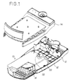
- FIG. 1 is a general view of a steam generator according to the invention.
- This generator comprises a housing assembly provided with a housing upper 14 and a lower housing 12 and inside which can be placed a Steam cassette 10.
- This connectable and disconnectable cassette by the user is connected to the upper and lower housings 14, 12 by clamps 20 having a classic structure of "clips" and allowing a quick extraction to proceed to the loading / unloading the cassette.
- the lower case 12 has a connection plate 16 on which comes into contact with the rear face of the cassette 10 in order to ensure the connections electrical and mechanical between this cassette and the generator body.
- the cassette 10 is in the form of a parallelepiped enclosure waterproof, without this particular form being limiting (it will be described later an example of a circular section cassette), inside which is fixed a envelope 18, the structure of which will be better detailed with reference to FIG. 2.
- the cassette 10 has on its internal surface ribs on which rests the envelope and which, by the difference in size of some of them, in maintain.
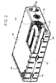
- FIG. 2 shows more precisely the structure of the envelope 18 which is present in the form of a parallelepiped made up of two half-housings, one upper 180 and the other lower 182, interconnected by fastening means 184, 186 arranged on each of these two half-housings, in order to facilitate the disassembly.
- the upper and lower faces of this parallelepiped are honeycombed a multitude of orifices 188.
- the envelope is filled with a porous material 190 surrounding an element heater, for example a heater resistor 192 (but electrodes or a ceramic resistance for example can also be used), this envelope intended to maintain the porous material geometrically with respect to water and keep its compression around the heating element.
- an element heater for example a heater resistor 192 (but electrodes or a ceramic resistance for example can also be used)
- this envelope intended to maintain the porous material geometrically with respect to water and keep its compression around the heating element.
- An intake port water 194 is practiced at the end of this envelope, the vapor produced by the water heating by the heating element escaping through the different alveoli 188.
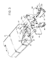
- FIG. 3 shows in detail the connections made between the cassette 10 and the connection plate 16 of the generator housing.
- the fixing means 20 of this cassette to the upper housing 14 of the generator (a similar means is present on the face bottom of the cassette to ensure a connection with the bottom box) or the heating resistance of the envelope which can consist of two resistors in series 192a, 192b and which emerges from the cassette by its rear face 22, to ensure its electrical connection with the connection plate 16.
- a conduit 24 fixed at the level of the inlet orifice 194 of the envelope also emerges from this rear face and crosses the connection plate 16 in order to be fixed tightly (this tightness being guaranteed by the use of an O-ring for example) on a water supply nozzle 26.
- sealing means 28 of the water intake orifice 194 (see figure 1) which are activated when the internal pressure of the cassette is lower than a specified pressure, eliminating the risk of vapor rejection through the water intake port.
- a steam outlet orifice 30 is made. also on the rear side of the cassette for steam evacuation escaping through the cells 188 of the envelope 18 contained in this cassette.
- Notches, for example 32 and 34, made in the body of the cassette allow to receive electrical contacts or electrodes allowing various detections.
- a detection of the water level, high and low allowing to check an overflow or a lack of water in the cassette can be implemented.
- a detection of the horizontality of this cassette can also be carried out. Electrodes intended for measuring the conductivity of water before evaporation must also be provided to allow a change of the porous material when it becomes scaled by the presence of limestone or non-mineral too much soluble.
- Steam regulation means 36 at the outlet of the cassette are provided in order to limit the vapor volume created and to obtain a continuous emission of steam.
- These means include a solenoid valve and a pressure switch whose pressure setting (steam pressure produced) is preferably chosen to be less than 0.5 bar.
- the diameter of the steam outlet conduits will be adapted in consequence to limit the pressure losses.
- the nozzle 26 has a siphon portion 260 to limit the height of the cassette water filling.
- a contactor 262 placed on this nozzle activates the electrodes for measuring the water level during filling.
- These filling means 26 also include means for cut off the water supply, for example a cam contact 264, controlled from the rotation of a water filling cap 266 placed at the inlet of these filling means and thus prohibiting any production of steam.
- the operation of the generator according to the invention is particularly simple.
- the water being introduced into the generator through the nozzle 26 (the plug of filling having of course been previously removed, this withdrawal causing a cut automatic heating), this gradually fills the envelope.
- the different electrodes make it possible to ensure the proper functioning of this filling and signal the moment of its stop to an electronic control unit 40 (see figure 4).
- the cap can therefore be closed again, the generator being ready for use.
- Activation of the heating resistance produces steam which escaping through the cells of the envelope emerges from the cassette by the steam outlet orifice to be distributed (after regulation) to the zone (s) use of this steam.
- Light or sound indicators 420, 410 are designed to alert the user to the need for water level monitoring reload the cassette with water. A check of the flatness (horizontality) of the cassette is also performed.
- the water supply to this cassette is carried out by a pump from a water tank outside the generator.
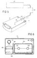
- FIG. 5 shows another embodiment of a generator.
- steam according to the invention supplied by a pump-reservoir assembly.
- the reservoir 60 has cold water and can be filled at any time without any capacity limitation. It can be removable or not.
- a pump 50 serving as a valve and preventing any return of hot water to the tank.
- This pump allows to introduce a minimum of water in the generator to keep it running knowing that the less there is faster water production is steam.
- the generator will include adequate detection devices, in particular level detection of water inside the generator, to determine the instants of control of the pump.
- the pump can be controlled to fill the lower part of the cassette 10 and thus soak the lower part of the porous material (the capillary body 190) which is heated by the resistor heating 192, the water being transformed from droplets within the capillary body in steam which escapes through the steam outlet orifice 30.
- the direct arrival of water above this porous material for example by means a spray bar 19 arranged above the casing 18 of the cassette 10 and connected to the water inlet duct 24.
- the lower part of the cassette which provides volume scaling of the body capillary pressed around the heating resistor, this supply from above essentially causes scaling on the upper part of this porous body.
- FIG. 6 shows an example of a cassette using two porous bodies 18a, 18b, one of which is directly soaked with water from a spraying boom constitutes a limestone trap.
- This ramp 19 brings the water pumped from the reservoir into an area comprising the second porous material 18b and separated from the area evaporator comprising the first porous material 18a surrounding the resistance heater 192 by a wall 196 extending between two opposite edges of this cassette leaving a free space for the passage of steam from the contiguous evaporation zone.
- Cold water from the tank is sprayed onto the upper part of the second material and creates there, due to the heat released by the vapor produced in the evaporation zone, precipitation of salts and in particular tartar.
- the partially descaled water will pass through the body porous 18b and come to settle on the bottom of the cassette from where it will irrigate, at through connecting holes 198 drilled in the wall 196, the first porous body 18a housed in the evaporation zone from where the steam escapes through the outlet steam 30.
- FIG. 7 is another embodiment of the cassette 10 which has a cylindrical shape.
- the porous body 190 and the resistance 192 are integrated in a ring 200, advantageously in material plastic, concentric with the outer casing of the cassette and sparing in its centers a free cylinder in which engages up to about half of its height a vapor outlet tube 202 secured to this outer casing.
- the volume of water injected by the pump and resting at the bottom of the cassette is determined to avoid a flow through the steam outlet tube during a reversal of this cassette. This volume (i.e.
- the level of water in the envelope can be controlled by means of a set of electrical contacts comprising by example the shielding of resistors 192 and a metal strip 204 applied against the internal part of the envelope 10.
- the envelope can be mounted in two separable parts to facilitate maintenance, i.e. changing the element of heating or porous material.
- FIG. 8 a particular embodiment of the cassette 10 is illustrated.
- a resistance preferably of ceramic type 210, inserted, by crimping or fitting for example, in the center of a diffuser 212 produced in a heat conductive material such as aluminum for example and provided at least three fins 214a to 214d placed on either side of its center.
- a porous body 216 is inserted under pressure (compressed) between each fin and held in place by a perforated circular envelope 218 advantageously consisting of a simple grid.
- Figure 9 attempts to illustrate very schematically a method allowing a soiling of a cassette to allow its reuse.
- pumping means for example the water supply pump 50
- a water tank for example the external tank 60
- the pump draws water from the tank and enters it into the cassette where it is heated to a determined temperature below its evaporation value but above 60 ° C, to retain tartar and insoluble minerals.
- the water can then be extracted through the steam outlet 30.
Landscapes
- Engineering & Computer Science (AREA)
- Mechanical Engineering (AREA)
- Sustainable Development (AREA)
- Sustainable Energy (AREA)
- Physics & Mathematics (AREA)
- Thermal Sciences (AREA)
- Life Sciences & Earth Sciences (AREA)
- General Engineering & Computer Science (AREA)
- Engine Equipment That Uses Special Cycles (AREA)
- Air Humidification (AREA)
- Thermotherapy And Cooling Therapy Devices (AREA)
- Devices For Medical Bathing And Washing (AREA)
- Apparatus For Disinfection Or Sterilisation (AREA)
- Finger-Pressure Massage (AREA)
- Resistance Heating (AREA)
Claims (18)
- Dampferzeuger mit einer Hülle (18), in der ein poröses Material (190) und ein dieses poröse Material (190) durchquerendes Heizelement (192) enthalten sind, wobei die Hülle (18) selbst in einem Behälter (10) angeordnet ist, der im Betrieb mit Mitteln zur Wasserzufuhr, Mitteln zur Steuerung des Heizelements und Mitteln zur Entnahme des Dampfs, der durch die Erwärmung des in den Behälter eingeführten Wassers erzeugt wird, verbunden ist, dadurch gekennzeichnet, daß der Behälter (10) eine dichte, lösbare Kassette bildet, die mittels Klammern (20), welche eine schnelle Verbindung und ein schnelles Lösen ermöglichen, mit einem festen Teil des Dampferzeugers (12, 14) verbunden ist, der die Mittel zur Wasserzufuhr, die Mittel zur Steuerung des Heizelements und die Mittel zur Dampfentnahme aufweist.
- Dampferzeuger nach Anspruch 1, dadurch gekennzeichnet, daß die Mittel für die Wasserzufuhr einen externen Tank (60) und eine Pumpe (50) aufweisen, die zwischen diesem Tank und einer Wasserzufuhröffnung angeordnet ist und eine selektive Wasserzufuhr in den Dampferzeuger ermöglicht.
- Dampferzeuger nach Anspruch 2, dadurch gekennzeichnet, daß das aus dem Tank (60) gepumpte Wasser mittels einer Berieselungsrampe (19) in einen oberen Bereich der Kassette (10) eingeführt wird.
- Dampferzeuger nach Anspruch 1, dadurch gekennzeichnet, daß die Mittel zur Wasserzufuhr Mittel (26) zur manuellen Füllung aufweisen, die einen Siphon (260) enthalten, um die Höhe der Füllung der Kassette mit Wasser zu begrenzen.
- Dampferzeuger nach Anspruch 4, dadurch gekennzeichnet, daß die Mittel zur manuellen Füllung weiter Mittel (264) zur Unterbrechung der Heizung und der Wasserzufuhr aufweisen, die ausgehend von der Drehung eines Einfüllverschlusses (266) gesteuert werden, der am Eingang dieser Füllmittel angeordnet ist.
- Dampferzeuger nach Anspruch 1, dadurch gekennzeichnet, daß er außerdem Mittel (36) zur Regulierung des Dampfs am Ausgang der Kassette (10) aufweist.
- Dampferzeuger nach Anspruch 1, dadurch gekennzeichnet, daß er außerdem Anzeigelampen (420) oder akustische Anzeiger (410) zur Kontrolle des Wasserpegels, der Ebenheit und der Kesselsteinablagerung in der Kassette (10) enthält.
- Dampferzeuger nach Anspruch 7, dadurch gekennzeichnet, daß die Kontrolle der Kesselsteinablagerung durch eine Vorrichtung (40) zur Messung der spezifischen Leitfähigkeit des Wassers vor der Verdampfung erhalten wird, die mit der Kassette (10) verbunden ist.
- Lösbare Dampfkassette, die mit einem Dampferzeuger gemäß einem beliebigen der Ansprüche 1 bis 8 verwendet werden soll, die einen äußeren, dichten Behälter aufweist, wobei eine Wasserzufuhr-Rohrleitung (24) dieses Wasser an eine innere Hülle (18) ausgibt, die ein Heizelement (192) für das Wasser enthält, um das herum ein erstes poröses Material (190) komprimiert ist, wobei diese Hülle auf ihrer ganzen Oberfläche Öffnungen (188) für den Auslaß des vom Heizelement erzeugten Dampfs aufweist und der Dampf aus der Kassette durch eine Dampfaustrittsöffnung (30) hinausgestoßen wird, und die lösbare Kassette mit Klammern (20) versehen ist, um eine schnelle Verbindung und ein schnelles Lösen des den äußeren Behälter der Kassette bildenden Gehäuses in Bezug auf den festen Teil (12, 14) des Dampferzeugers zu ermöglichen.
- Lösbare Dampfkassette nach Anspruch 9, dadurch gekennzeichnet, daß sie Mittel (28) für den Verschluß der Wasserzufuhröffnung aufweist, die aktiviert werden, wenn der innere Druck der Kassette unter einem vorbestimmten Druck liegt.
- Lösbare Dampfkassette nach Anspruch 9, dadurch gekennzeichnet, daß sie weiter ein zweites poröses Material (18b) enthält, das vom ersten, das Heizelement (192) umgebenden porösen Material (18a) durch eine Wand (196) getrennt ist, die sich zwischen zwei entgegengesetzten Rändern der Kassette erstreckt und einen Freiraum für den Durchlaß des Dampfes läßt, wobei das zweite poröse Material (18b), das eine Falle für den Kalk bildet, über eine Berieselungsrampe (19) direkt mit dem aus dem Tank gepumpten Wasser getränkt wird.
- Lösbare Dampfkassette nach Anspruch 11, dadurch gekennzeichnet, daß die Wand (196) Verbindungsöffnungen (198) zwischen der Verdampfungszone, die das erste poröse Material (18a) enthält, und der Wasserzufuhrzone aufweist, die das zweite poröse Material (18b) enthält, um eine Berieselung des ersten porösen Materials mit teilweise von Kesselstein befreitem Wasser zu ermöglichen, das das zweite poröse Material durchquert hat.
- Lösbare Dampfkassette nach Anspruch 9, dadurch gekennzeichnet, daß das erste poröse Material und das Heizelement in einen Ring (200) integriert sind, der vorteilhafterweise aus Kunststoffmaterial besteht, der konzentrisch zum äußeren Behälter der Kassette (10) ist und in seiner Mitte einen freien Zylinder bildet, in den bis etwa in die Mitte seiner Höhe ein Dampfaustrittsrohr (202) eingeführt ist, das fest mit diesem kreisförmigen äußeren Behälter verbunden ist.
- Lösbare Dampfkassette nach einem beliebigen der Ansprüche 9, 11 und 13, dadurch gekennzeichnet, daß die Hülle (18) von zwei trennbaren Halbgehäusen (180, 182; 200) gebildet wird, die eine obere und eine untere mit wabenförmigen Öffnungen versehene Seite aufweisen, um einen leichten Austausch des porösen Materials oder des Heizelements zu ermöglichen.
- Lösbare Dampfkassette nach einem beliebigen der Ansprüche 9, 11 und 13, dadurch gekennzeichnet, daß das Heizelement (192) des im porösen Material strömenden Wassers ausgewählt wird aus den Elementen der folgenden Gruppe: Heizwiderstand, Keramikwiderstand oder Elektroden.
- Lösbare Dampfkassette nach Anspruch 9, dadurch gekennzeichnet, daß das Element zum Erwärmen des Wassers aus einem Keramikwiderstand (210) besteht, der in die Mitte eines Diffusorelements (212) aus wärmeleitendem Material eingefügt ist, wobei das erste poröse Material (216) unter Druck zwischen mindestens drei Rippen (214a bis 214d) dieses Diffusors eingesetzt und durch die innere gelochte Hülle (218) an Ort und Stelle gehalten wird.
- Lösbare Dampfkassette nach einem beliebigen der Ansprüche 9 bis 16, dadurch gekennzeichnet, daß sie Mittel zur Erfassung des hohen und des niederen Wasserpegels aufweist, die mit Mitteln (40) zur Kontrolle dieser Pegel zusammenwirken, welche im festen Teil des Dampferzeugers angeordnet sind.
- Lösbare Dampfkassette nach Anspruch 17, dadurch gekennzeichnet, daß zur Bestimmung des Vorhandenseins eines bestimmten Wasserpegels im Behälter diese Erfassungsmittel weiter einen Satz von elektrischen Kontakten aufweisen, die einerseits die Abschirmung des Heizelements (192) und andererseits ein metallisches Band (204) enthalten, das gegen den inneren Bereich des äußeren Behälters der Kassette (10) angelegt ist.
Applications Claiming Priority (2)
| Application Number | Priority Date | Filing Date | Title |
|---|---|---|---|
| FR9313840A FR2712668B1 (fr) | 1993-11-19 | 1993-11-19 | Générateur de vapeur rechargeable. |
| FR9313840 | 1993-11-19 |
Publications (2)
| Publication Number | Publication Date |
|---|---|
| EP0654635A1 EP0654635A1 (de) | 1995-05-24 |
| EP0654635B1 true EP0654635B1 (de) | 1998-06-17 |
Family
ID=9453034
Family Applications (1)
| Application Number | Title | Priority Date | Filing Date |
|---|---|---|---|
| EP94402422A Expired - Lifetime EP0654635B1 (de) | 1993-11-19 | 1994-10-27 | Wiederaufladbarer Dampferzeuger |
Country Status (7)
| Country | Link |
|---|---|
| US (1) | US5602958A (de) |
| EP (1) | EP0654635B1 (de) |
| JP (1) | JPH07198104A (de) |
| AT (1) | ATE167562T1 (de) |
| DE (1) | DE69411127T2 (de) |
| ES (1) | ES2117231T3 (de) |
| FR (1) | FR2712668B1 (de) |
Families Citing this family (14)
| Publication number | Priority date | Publication date | Assignee | Title |
|---|---|---|---|---|
| DE29504734U1 (de) * | 1995-03-20 | 1996-07-18 | Perycut-Chemie AG, Zürich | Verdampfervorrichtung |
| US5945094A (en) * | 1997-04-14 | 1999-08-31 | S. C. Johnson & Son, Inc. | Disposable plug-in dispenser for use with air freshener and the like |
| US5903710A (en) * | 1997-04-14 | 1999-05-11 | S. C. Johnson & Son, Inc. | Air freshener dispenser device with disposable heat-promoted cartridge |
| ITPD980079A1 (it) * | 1998-04-02 | 1999-10-02 | Carel Srl | Dispositivo per la rilevazione dello spessore delle incrostazioni sugl i elementi resistivi di generatori di vapore a resistenze elettriche |
| DE29822527U1 (de) * | 1998-12-17 | 1999-02-11 | Tsai, Sam, Taipeh/T'ai-pei | Multifunktioneller, elektrischer Dampfreiniger |
| US6169852B1 (en) | 1999-04-20 | 2001-01-02 | The Hong Kong University Of Science & Technology | Rapid vapor generator |
| DE10234625B4 (de) * | 2002-07-29 | 2005-02-24 | Rational Ag | Dampferzeuger mit Reaktor zur Kalkkristallkeimbildung |
| JP4573250B2 (ja) * | 2004-11-10 | 2010-11-04 | コーニンクレッカ フィリップス エレクトロニクス エヌ ヴィ | 単線を用い双方向通信を実行する方法及び装置 |
| US7219628B1 (en) | 2004-11-17 | 2007-05-22 | Texaco Inc. | Vaporizer and methods relating to same |
| WO2006070317A1 (en) * | 2004-12-28 | 2006-07-06 | Koninklijke Philips Electronics N.V. | Measures for keeping a degree of contamination of a steam generator including its contents below a predetermined maximum |
| PL1861539T3 (pl) | 2005-03-25 | 2015-08-31 | Lg Electronics Inc | Maszyna pralnicza oraz sposób jej sterowania |
| KR101215347B1 (ko) * | 2005-08-29 | 2012-12-26 | 엘지전자 주식회사 | 드럼세탁기의 스팀발생장치 및 그 제어방법 |
| KR100774181B1 (ko) * | 2005-09-01 | 2007-11-07 | 엘지전자 주식회사 | 증기발생장치 |
| US20190308228A1 (en) * | 2018-04-06 | 2019-10-10 | A.J.Antines & Co. | System and method for cleaning steam generators |
Family Cites Families (3)
| Publication number | Priority date | Publication date | Assignee | Title |
|---|---|---|---|---|
| FR2595052B1 (fr) * | 1986-03-03 | 1990-06-01 | Armines | Procede et dispositif de vaporisation rapide d'un liquide |
| FR2623600B1 (fr) * | 1987-11-19 | 1990-04-06 | Armines | Generateur de vapeur |
| FR2625293B1 (fr) * | 1987-12-24 | 1990-06-01 | Armines | Appareil electro-portatif pour la production de vapeur, notamment pour le decollage de revetements muraux |
-
1993
- 1993-11-19 FR FR9313840A patent/FR2712668B1/fr not_active Expired - Fee Related
-
1994
- 1994-10-27 AT AT94402422T patent/ATE167562T1/de not_active IP Right Cessation
- 1994-10-27 EP EP94402422A patent/EP0654635B1/de not_active Expired - Lifetime
- 1994-10-27 DE DE69411127T patent/DE69411127T2/de not_active Expired - Fee Related
- 1994-10-27 ES ES94402422T patent/ES2117231T3/es not_active Expired - Lifetime
- 1994-11-10 US US08/337,998 patent/US5602958A/en not_active Expired - Fee Related
- 1994-11-15 JP JP6280841A patent/JPH07198104A/ja active Pending
Also Published As
| Publication number | Publication date |
|---|---|
| ES2117231T3 (es) | 1998-08-01 |
| ATE167562T1 (de) | 1998-07-15 |
| JPH07198104A (ja) | 1995-08-01 |
| DE69411127D1 (de) | 1998-07-23 |
| FR2712668B1 (fr) | 1996-02-09 |
| FR2712668A1 (fr) | 1995-05-24 |
| EP0654635A1 (de) | 1995-05-24 |
| US5602958A (en) | 1997-02-11 |
| DE69411127T2 (de) | 1998-11-19 |
Similar Documents
| Publication | Publication Date | Title |
|---|---|---|
| EP0654635B1 (de) | Wiederaufladbarer Dampferzeuger | |
| FR3060027A1 (fr) | Appareil de defroissage a la vapeur | |
| EP3064640B1 (de) | Elektrohaushaltsgerät zum bügeln, das einen behälter umfasst, der einen wasserenthärter und einen dampfverteilungskreislauf mit einem filter umfasst | |
| FR2915344A1 (fr) | Dispositif de chauffage de fluide et appareil d'epuration de gaz d'echappement, equipe d'un tel dispositif. | |
| FR2611867A1 (fr) | Rechauffeur tubulaire a ailettes | |
| EP3580385B1 (de) | Bügeleisen mit einer vorrichtung zum rückhalten von durch dampf transportierten kalkpartikeln | |
| EP2578743A1 (de) | Elektrohaushaltsgerät, das einen Dampfverteilungskreis umfasst | |
| EP2578742B1 (de) | Bügelgerät, das einen Dampfverteilungskreislauf umfasst | |
| EP1839762A1 (de) | Optimiertes Sprühverfahren für Flüssigkeiten und Vorrichtung zum Sprühen von Flüssigkeiten für die Umsetzung dieses Verfahrens | |
| EP3643831B1 (de) | Verfahren zur reinigung eines bügeleisens, das mit einem hohlraum zur sammlung von kalkablagerungen ausgestattet ist | |
| FR2738661A1 (fr) | Dispositif et procede de recuperation et de refroidissement du coeur en fusion d'un reacteur nucleaire | |
| EP3418440B1 (de) | Gerät für die wäschebehandlung, das einen dampferzeuger mit flashverdampfung umfasst | |
| CH618292A5 (de) | ||
| EP2916965B1 (de) | Mit gespeicherter obsoleszenz ausgetattete kartusche zur erzeugung und ausgabe eines aerosols und sprühvorrichtung mit einer solchen kartusche | |
| FR2645624A1 (fr) | Generateur de vapeur d'eau, et son application a un appareil pour fondre la cire d'abeille | |
| EP0597748B1 (de) | Schnelldampferzeuger | |
| FR2621083A1 (fr) | Pompe immergee de prelevement de liquide dans une conduite, notamment une conduite de rejet en eau profonde d'eaux de refroidissement de centrale nucleaire | |
| FR2983692A1 (fr) | Dispositif de chauffage pour amener du liquide a l'ebullition et appareil de preparation de boisson comportant un tel dispositif | |
| FR2691233A1 (fr) | Générateur de vapeur à réponse instantanée. | |
| EP2578745B1 (de) | Bügeleisen, das einen Dampfverteilungskreislauf mit einem Filtergitter umfasst | |
| EP4349502B1 (de) | Vorrichtung zum reinigen eines gegenstandes | |
| FR3097883A1 (fr) | Fer à repasser comportant un dispositif de rétention des particules de tartre transportées par la vapeur. | |
| FR3137110A1 (fr) | APPareil electromenager de repassage et/OU defroissage COMPORTANT un DISPOSITIF DE RETENTION des particules de tartre transportées par la vapeur | |
| FR2604846A1 (fr) | Generateur electrothermique a conduction directe | |
| FR2666384A1 (fr) | Pompe a diffusion. |
Legal Events
| Date | Code | Title | Description |
|---|---|---|---|
| PUAI | Public reference made under article 153(3) epc to a published international application that has entered the european phase |
Free format text: ORIGINAL CODE: 0009012 |
|
| AK | Designated contracting states |
Kind code of ref document: A1 Designated state(s): AT BE CH DE DK ES FR GB GR IE IT LI LU NL PT SE |
|
| 17P | Request for examination filed |
Effective date: 19950830 |
|
| 17Q | First examination report despatched |
Effective date: 19961017 |
|
| GRAG | Despatch of communication of intention to grant |
Free format text: ORIGINAL CODE: EPIDOS AGRA |
|
| GRAG | Despatch of communication of intention to grant |
Free format text: ORIGINAL CODE: EPIDOS AGRA |
|
| GRAH | Despatch of communication of intention to grant a patent |
Free format text: ORIGINAL CODE: EPIDOS IGRA |
|
| GRAH | Despatch of communication of intention to grant a patent |
Free format text: ORIGINAL CODE: EPIDOS IGRA |
|
| GRAA | (expected) grant |
Free format text: ORIGINAL CODE: 0009210 |
|
| AK | Designated contracting states |
Kind code of ref document: B1 Designated state(s): AT BE CH DE DK ES FR GB GR IE IT LI LU NL PT SE |
|
| PG25 | Lapsed in a contracting state [announced via postgrant information from national office to epo] |
Ref country code: GR Free format text: LAPSE BECAUSE OF FAILURE TO SUBMIT A TRANSLATION OF THE DESCRIPTION OR TO PAY THE FEE WITHIN THE PRESCRIBED TIME-LIMIT Effective date: 19980617 Ref country code: AT Free format text: LAPSE BECAUSE OF FAILURE TO SUBMIT A TRANSLATION OF THE DESCRIPTION OR TO PAY THE FEE WITHIN THE PRESCRIBED TIME-LIMIT Effective date: 19980617 |
|
| REF | Corresponds to: |
Ref document number: 167562 Country of ref document: AT Date of ref document: 19980715 Kind code of ref document: T |
|
| REG | Reference to a national code |
Ref country code: CH Ref legal event code: EP |
|
| GBT | Gb: translation of ep patent filed (gb section 77(6)(a)/1977) |
Effective date: 19980619 |
|
| REF | Corresponds to: |
Ref document number: 69411127 Country of ref document: DE Date of ref document: 19980723 |
|
| REG | Reference to a national code |
Ref country code: CH Ref legal event code: NV Representative=s name: BOVARD AG PATENTANWAELTE |
|
| REG | Reference to a national code |
Ref country code: ES Ref legal event code: FG2A Ref document number: 2117231 Country of ref document: ES Kind code of ref document: T3 |
|
| ITF | It: translation for a ep patent filed | ||
| PG25 | Lapsed in a contracting state [announced via postgrant information from national office to epo] |
Ref country code: SE Free format text: LAPSE BECAUSE OF FAILURE TO SUBMIT A TRANSLATION OF THE DESCRIPTION OR TO PAY THE FEE WITHIN THE PRESCRIBED TIME-LIMIT Effective date: 19980917 Ref country code: PT Free format text: LAPSE BECAUSE OF FAILURE TO SUBMIT A TRANSLATION OF THE DESCRIPTION OR TO PAY THE FEE WITHIN THE PRESCRIBED TIME-LIMIT Effective date: 19980917 Ref country code: DK Free format text: LAPSE BECAUSE OF FAILURE TO SUBMIT A TRANSLATION OF THE DESCRIPTION OR TO PAY THE FEE WITHIN THE PRESCRIBED TIME-LIMIT Effective date: 19980917 |
|
| REG | Reference to a national code |
Ref country code: IE Ref legal event code: FG4D Free format text: FRENCH |
|
| PG25 | Lapsed in a contracting state [announced via postgrant information from national office to epo] |
Ref country code: LU Free format text: LAPSE BECAUSE OF NON-PAYMENT OF DUE FEES Effective date: 19981027 |
|
| PG25 | Lapsed in a contracting state [announced via postgrant information from national office to epo] |
Ref country code: BE Free format text: LAPSE BECAUSE OF NON-PAYMENT OF DUE FEES Effective date: 19981031 |
|
| PG25 | Lapsed in a contracting state [announced via postgrant information from national office to epo] |
Ref country code: IE Free format text: LAPSE BECAUSE OF NON-PAYMENT OF DUE FEES Effective date: 19990219 |
|
| REG | Reference to a national code |
Ref country code: IE Ref legal event code: FD4D |
|
| PLBE | No opposition filed within time limit |
Free format text: ORIGINAL CODE: 0009261 |
|
| STAA | Information on the status of an ep patent application or granted ep patent |
Free format text: STATUS: NO OPPOSITION FILED WITHIN TIME LIMIT |
|
| BERE | Be: lapsed |
Owner name: S.A. SUPERBA Effective date: 19981031 |
|
| 26N | No opposition filed | ||
| REG | Reference to a national code |
Ref country code: FR Ref legal event code: ST |
|
| REG | Reference to a national code |
Ref country code: FR Ref legal event code: RN |
|
| REG | Reference to a national code |
Ref country code: FR Ref legal event code: RN |
|
| PGFP | Annual fee paid to national office [announced via postgrant information from national office to epo] |
Ref country code: NL Payment date: 20000918 Year of fee payment: 7 |
|
| PGFP | Annual fee paid to national office [announced via postgrant information from national office to epo] |
Ref country code: ES Payment date: 20001016 Year of fee payment: 7 |
|
| PGFP | Annual fee paid to national office [announced via postgrant information from national office to epo] |
Ref country code: CH Payment date: 20001018 Year of fee payment: 7 |
|
| REG | Reference to a national code |
Ref country code: FR Ref legal event code: TP |
|
| PG25 | Lapsed in a contracting state [announced via postgrant information from national office to epo] |
Ref country code: ES Free format text: LAPSE BECAUSE OF NON-PAYMENT OF DUE FEES Effective date: 20011028 |
|
| PG25 | Lapsed in a contracting state [announced via postgrant information from national office to epo] |
Ref country code: LI Free format text: LAPSE BECAUSE OF NON-PAYMENT OF DUE FEES Effective date: 20011031 Ref country code: CH Free format text: LAPSE BECAUSE OF NON-PAYMENT OF DUE FEES Effective date: 20011031 |
|
| REG | Reference to a national code |
Ref country code: GB Ref legal event code: IF02 |
|
| PG25 | Lapsed in a contracting state [announced via postgrant information from national office to epo] |
Ref country code: NL Free format text: LAPSE BECAUSE OF NON-PAYMENT OF DUE FEES Effective date: 20020501 |
|
| REG | Reference to a national code |
Ref country code: CH Ref legal event code: PL |
|
| NLV4 | Nl: lapsed or anulled due to non-payment of the annual fee |
Effective date: 20020501 |
|
| REG | Reference to a national code |
Ref country code: ES Ref legal event code: FD2A Effective date: 20021113 |
|
| PGFP | Annual fee paid to national office [announced via postgrant information from national office to epo] |
Ref country code: DE Payment date: 20061009 Year of fee payment: 13 |
|
| PGFP | Annual fee paid to national office [announced via postgrant information from national office to epo] |
Ref country code: GB Payment date: 20061010 Year of fee payment: 13 |
|
| PGFP | Annual fee paid to national office [announced via postgrant information from national office to epo] |
Ref country code: IT Payment date: 20061031 Year of fee payment: 13 Ref country code: FR Payment date: 20061031 Year of fee payment: 13 |
|
| GBPC | Gb: european patent ceased through non-payment of renewal fee |
Effective date: 20071027 |
|
| PG25 | Lapsed in a contracting state [announced via postgrant information from national office to epo] |
Ref country code: DE Free format text: LAPSE BECAUSE OF NON-PAYMENT OF DUE FEES Effective date: 20080501 |
|
| REG | Reference to a national code |
Ref country code: FR Ref legal event code: ST Effective date: 20080630 |
|
| PG25 | Lapsed in a contracting state [announced via postgrant information from national office to epo] |
Ref country code: GB Free format text: LAPSE BECAUSE OF NON-PAYMENT OF DUE FEES Effective date: 20071027 |
|
| PG25 | Lapsed in a contracting state [announced via postgrant information from national office to epo] |
Ref country code: FR Free format text: LAPSE BECAUSE OF NON-PAYMENT OF DUE FEES Effective date: 20071031 |
|
| PG25 | Lapsed in a contracting state [announced via postgrant information from national office to epo] |
Ref country code: IT Free format text: LAPSE BECAUSE OF NON-PAYMENT OF DUE FEES Effective date: 20071027 |