EP0654635A1 - Wiederaufladbarer Dampferzeuger - Google Patents
Wiederaufladbarer Dampferzeuger Download PDFInfo
- Publication number
- EP0654635A1 EP0654635A1 EP94402422A EP94402422A EP0654635A1 EP 0654635 A1 EP0654635 A1 EP 0654635A1 EP 94402422 A EP94402422 A EP 94402422A EP 94402422 A EP94402422 A EP 94402422A EP 0654635 A1 EP0654635 A1 EP 0654635A1
- Authority
- EP
- European Patent Office
- Prior art keywords
- cassette
- water
- steam
- porous material
- heating element
- Prior art date
- Legal status (The legal status is an assumption and is not a legal conclusion. Google has not performed a legal analysis and makes no representation as to the accuracy of the status listed.)
- Granted
Links
- XLYOFNOQVPJJNP-UHFFFAOYSA-N water Substances O XLYOFNOQVPJJNP-UHFFFAOYSA-N 0.000 claims abstract description 100
- 238000010438 heat treatment Methods 0.000 claims abstract description 47
- 239000011148 porous material Substances 0.000 claims abstract description 42
- 238000011049 filling Methods 0.000 claims description 20
- 238000001704 evaporation Methods 0.000 claims description 13
- 230000008020 evaporation Effects 0.000 claims description 13
- 239000000919 ceramic Substances 0.000 claims description 6
- 238000001514 detection method Methods 0.000 claims description 6
- 230000001276 controlling effect Effects 0.000 claims description 5
- 238000012544 monitoring process Methods 0.000 claims description 4
- 235000008733 Citrus aurantifolia Nutrition 0.000 claims description 3
- 235000011941 Tilia x europaea Nutrition 0.000 claims description 3
- 239000004571 lime Substances 0.000 claims description 3
- 229910052751 metal Inorganic materials 0.000 claims description 3
- 239000002184 metal Substances 0.000 claims description 3
- 230000001105 regulatory effect Effects 0.000 claims description 3
- 239000004020 conductor Substances 0.000 claims description 2
- 230000002262 irrigation Effects 0.000 claims description 2
- 238000003973 irrigation Methods 0.000 claims description 2
- 238000004519 manufacturing process Methods 0.000 description 4
- 239000000463 material Substances 0.000 description 4
- 238000012423 maintenance Methods 0.000 description 3
- 208000006558 Dental Calculus Diseases 0.000 description 2
- 235000019738 Limestone Nutrition 0.000 description 2
- 230000008859 change Effects 0.000 description 2
- 238000005520 cutting process Methods 0.000 description 2
- 229910052500 inorganic mineral Inorganic materials 0.000 description 2
- 239000006028 limestone Substances 0.000 description 2
- 238000000034 method Methods 0.000 description 2
- 239000011707 mineral Substances 0.000 description 2
- 238000007789 sealing Methods 0.000 description 2
- 238000009834 vaporization Methods 0.000 description 2
- 230000008016 vaporization Effects 0.000 description 2
- 230000004913 activation Effects 0.000 description 1
- 229910052782 aluminium Inorganic materials 0.000 description 1
- XAGFODPZIPBFFR-UHFFFAOYSA-N aluminium Chemical compound [Al] XAGFODPZIPBFFR-UHFFFAOYSA-N 0.000 description 1
- 230000015572 biosynthetic process Effects 0.000 description 1
- 230000006835 compression Effects 0.000 description 1
- 238000007906 compression Methods 0.000 description 1
- 239000000470 constituent Substances 0.000 description 1
- 238000010924 continuous production Methods 0.000 description 1
- 238000002788 crimping Methods 0.000 description 1
- 230000006378 damage Effects 0.000 description 1
- 238000009826 distribution Methods 0.000 description 1
- 238000000605 extraction Methods 0.000 description 1
- 239000012530 fluid Substances 0.000 description 1
- 238000002347 injection Methods 0.000 description 1
- 239000007924 injection Substances 0.000 description 1
- 238000011068 loading method Methods 0.000 description 1
- 230000035515 penetration Effects 0.000 description 1
- 238000001556 precipitation Methods 0.000 description 1
- 238000005086 pumping Methods 0.000 description 1
- 230000009467 reduction Effects 0.000 description 1
- 230000000284 resting effect Effects 0.000 description 1
- 150000003839 salts Chemical class 0.000 description 1
- 238000000926 separation method Methods 0.000 description 1
- 239000000243 solution Substances 0.000 description 1
- 239000007921 spray Substances 0.000 description 1
- 238000005507 spraying Methods 0.000 description 1
- 230000009466 transformation Effects 0.000 description 1
Images


Classifications
-
- F—MECHANICAL ENGINEERING; LIGHTING; HEATING; WEAPONS; BLASTING
- F22—STEAM GENERATION
- F22B—METHODS OF STEAM GENERATION; STEAM BOILERS
- F22B1/00—Methods of steam generation characterised by form of heating method
- F22B1/28—Methods of steam generation characterised by form of heating method in boilers heated electrically
- F22B1/284—Methods of steam generation characterised by form of heating method in boilers heated electrically with water in reservoirs
- F22B1/285—Methods of steam generation characterised by form of heating method in boilers heated electrically with water in reservoirs the water being fed by a pump to the reservoirs
Definitions
- the present invention relates to a steam generator whose active part can be connected and disconnected directly by the user in order to provide for its replacement.
- a steam generator conventionally consists of a water tank comprising a filling duct and communicating with a distribution chamber by a water injection device, this chamber comprising an outlet orifice for the evaporation of the vapor created by heating the water in the tank.
- the present invention aims to overcome the aforementioned drawbacks, that is to say to provide a generator requiring no particular monitoring or maintenance or specific water treatment.
- Another object of the invention is to produce a steam generator which is simple to use, reliable and inexpensive.
- a steam generator comprising an orifice for supplying water with a porous material, a heating element passing through this porous material and an orifice for the outlet of the vapor created by the heating of this water, the porous material and its heating element being contained in an envelope disposed in a sealed, removable cassette and connected in operation to a fixed part of the generator containing means for supplying water, means for controlling the heating element and means for withdrawing the steam.
- the waterproof cassette is connected to the fixed part of the generator by means of clamps in order to allow a quick connection and disconnection.
- the water supply means may comprise an external reservoir and a pump placed between this reservoir and the water supply orifice of the generator and allowing selective introduction of water into the latter.
- the water pumped from the reservoir is introduced into an upper part of the cassette by means of a spray bar.
- this pump / tank assembly allows a continuous supply of the generator, the tank can be filled at any time without any capacity limitation.
- the water is introduced by the pump at a pressure higher than the internal pressure of the generator, it is easy to direct it to a place where its transformation into vapor is most effective or even where descaling can be carried out simply.
- the water supply means can also include manual filling means comprising a siphon to limit the height of the filling with water of the cassette, these filling means being provided with means for cutting off the heating and of the water supply controlled from the rotation of a filling plug placed at the inlet of these filling means.
- This automatic cut-off ensures maximum safety during filling while avoiding any production of steam during it.
- This generator also comprises means for regulating the steam at the outlet of the cassette making it possible to ensure continuous production of steam.
- Light or sound control indicators allow constant control of the water level, the flatness and the scaling of the cassette, this latter control being obtained by a device for measuring the conductivity of the water before evaporation which is connected to the cassette.
- the present invention also relates to the removable steam cassette intended to be used with the preceding steam generator. It includes a water inlet orifice distributing this water to an internal envelope containing a water heating element around which is compressed a first porous material, this envelope comprising over its entire surface orifices for the evacuation of the steam produced by the heating element and the steam being expelled from the cassette by a steam outlet orifice.
- a water inlet orifice distributing this water to an internal envelope containing a water heating element around which is compressed a first porous material, this envelope comprising over its entire surface orifices for the evacuation of the steam produced by the heating element and the steam being expelled from the cassette by a steam outlet orifice.
- the latter also comprises a second porous material separated from the first porous material surrounding the heating element by a wall extending between two opposite edges of the cassette, leaving a free space for the passage of steam, the second porous material which constitutes a trap for limestone being soaked directly by the water pumped from the reservoir through a spraying boom.
- the wall has connection orifices between the evaporation zone containing the first porous material and the water supply zone containing the second porous material, in order to allow irrigation of the first porous material from partially descaled water having passed through the second porous material.
- the first porous material and the heating element are integrated in a ring, advantageously made of plastic, concentric with the external envelope of the cassette and providing in its center a free cylinder in which engages up to about half of its height a steam outlet tube secured to this circular outer envelope.
- this envelope is formed of two separable half-housings having honeycombed upper and lower faces, in order to ensure easy replacement of the porous material or of the heating element (for example a heating resistance, a ceramic resistance or electrodes ).
- the heating element for example a heating resistance, a ceramic resistance or electrodes .
- the water heating element consists of a ceramic resistor inserted in the center of a diffuser element made of a heat conducting material, the first porous material being engaged under pressure between at least three fins of this diffuser and held in place by the perforated internal envelope.
- Means for detecting high and low water levels intended to cooperate with means for controlling these levels present in the fixed part of the generator allow constant monitoring of the proper functioning of the heat exchanges existing at the level of the cassette.
- the detection means further comprise a set of electrical contacts comprising on the one hand the shielding of the heating element and on the other hand a metal strip applied against the internal part of the envelope.
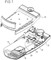
- FIG. 1 is a general view of a steam generator according to the invention.
- This generator comprises a housing assembly provided with an upper housing 12 and a lower housing 14 and inside which can be placed a steam cassette 10.
- This cassette which can be connected and disconnected by the user is connected to the upper and lower housings. 12, 14 by clamps 20 having a conventional structure of "clips" and allowing rapid extraction to proceed with loading / unloading of the cassette.
- the lower housing 12 comprises a connection plate 16 on which the rear face of the cassette 10 comes into contact in order to ensure the electrical and mechanical connections between this cassette and the body of the generator.
- the cassette 10 is in the form of a sealed parallelepiped enclosure, without this particular form being limiting (an example of a circular section cassette will be described later), inside which an envelope 18 is fixed, of which the structure will be better detailed with reference to FIG. 2.
- the cassette 10 has on its internal surface ribs on which the envelope rests and which, by the difference in size of some of them, ensure their maintenance.
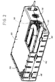
- FIG. 2 shows more precisely the structure of the envelope 18 which is in the form of a parallelepiped consisting of two half-housings, one upper 180 and the other lower 182, connected together by fixing means 184, 186 arranged on each of these two half-housings, in order to facilitate disassembly.
- the upper and lower faces of this parallelepiped are honeycombed with a multitude of orifices 188.
- the envelope is filled with a porous material 190 surrounding a heating element, for example a heating resistance 192 (but electrodes or a ceramic resistance for example can also be used), this envelope having for its object to maintain the porous material geometrically by water and keep its compression around the heating element. Given the temperatures involved, below 100 ° C., the envelope can be produced very simply and at low cost in a plastic material.
- a water inlet orifice 194 is formed at the end of this envelope, the vapor produced by the heating of the water by the heating resistor escaping through the various cells 188.
- FIG. 3 shows in detail the connections made between the cassette 10 and the connection plate 16 of the generator housing.
- the means 20 for fixing this cassette to the upper case 14 of the generator a similar means is present on the lower face of the cassette to ensure a connection with the lower case
- the heating resistance of the 'envelope which may consist of two resistors in series 192a, 192b and which emerges from the cassette by its rear face 22, to ensure its electrical connection with the connection plate 16.
- a conduit 24 fixed at the orifice inlet 194 of the casing also emerges from this rear face and passes through the connection plate 16 in order to be fixed in a sealed manner (this sealing being guaranteed by the use of an O-ring for example) on a nozzle for supplying water 26.
- sealing means 28 of the water intake orifice 194 (see Figure 1) which are activated when the internal pressure of the cassette is lower than a determined pressure, thus eliminating the risk of vapor rejection through the water intake orifice.
- a steam outlet orifice 30 is also made on the rear face of the cassette for the evacuation of the steam escaping through the cells 188 of the envelope 18 contained in this cassette.
- Notches, for example 32 and 34, made in the body of the cassette make it possible to receive electrical contacts or electrodes allowing various detections.
- a detection of the water level, high and low, making it possible to check an overflow or a lack of water in the cassette can be implemented.
- the horizontality of this cassette can also be detected.
- Electrodes intended for measuring the conductivity of the water before evaporation must also be provided, in order to allow a change of the porous material when it becomes scaled up by the presence of limestone or insoluble minerals in too large a quantity.
- Means for regulating the steam 36 at the outlet from the cassette are provided in order to limit the volume of steam created and to obtain a continuous emission of steam.
- These means include a solenoid valve and a pressure switch whose control pressure (vapor pressure produced) is preferably chosen to be less than 0.5 bar.
- control pressure vapor pressure produced
- the diameter of the steam outlet conduits will be adapted accordingly to limit the pressure drops.
- the endpiece 26 has a siphon portion 260 for automatically limiting the height of the filling of the cassette with water.
- a contactor 262 placed on this nozzle activates the electrodes for measuring the water level during filling.
- These filling means 26 further comprise means for cutting off the water supply, for example a cam contact 264, controlled from the rotation of a water filling plug 266 placed at the inlet of these means of filling and thus prohibiting any production of steam.
- the operation of the generator according to the invention is particularly simple.
- the water being introduced into the generator through the nozzle 26 (the filling plug having of course been removed beforehand, this withdrawal causing an automatic cut-off of the heating), the latter gradually fills the envelope.
- the different electrodes make it possible to ensure the proper functioning of this filling and to signal the instant of its stopping to an electronic control assembly 40 (see FIG. 4).
- the cap can therefore be closed again, the generator being ready for use.
- the activation of the heating resistance causes a production of vapor which escapes through the cells of the envelope emerges from the cassette by the steam outlet orifice to be distributed (after regulation) to the area or areas of use of this steam.
- Light or sound indicators 400, 410 are provided to indicate to the user by means of a control of the water level the need to recharge the cassette with water. A check of the flatness (horizontality) of the cassette is also carried out.
- the water supply to this cassette is carried out by a pump from a water tank outside the generator.
- the electronic control unit which includes the device for measuring the conductivity of the water.
- the light 400 or sound 410 indicators of this assembly make it possible to inform the user of the scaling of this cassette.
- FIG. 5 shows another embodiment of a steam generator according to the invention supplied by a pump-tank assembly.
- the tank 60 has cold water and can be filled at any time without any capacity limitation. It can be removable or not.
- a pump 50 serving as a valve and preventing any return of hot water to the reservoir.
- This pump allows a minimum of water to be introduced into the generator to ensure its operation, knowing that the less water there is, the faster the production of steam.
- the generator must include adequate detection devices, in particular for detecting the water level inside the generator, to determine the instants for controlling the pump.
- the pump can be controlled to fill the lower part of the cassette 10 and thus soak the lower part of the porous material (the capillary body 190) which is heated by the heating resistor 192, the water being transformed from droplets within the capillary body into vapor which escapes through the steam outlet orifice 30.
- the water inlet directly above this porous material, for example by means of a sprinkler 19 arranged above the '' envelope 18 of cassette 10 and connected to the water inlet duct 24.
- this supply from above essentially causes a scaling on the upper part of this porous body.
- FIG. 6 shows an example of a cassette using two porous bodies 18a, 18b, one of which is soaked directly with water from a watering ramp constitutes a trap for lime.
- This ramp 19 brings the water pumped from the tank into a zone comprising the second porous material 18b and separated from the evaporation zone comprising the first porous material 18a surrounding the heating resistor 192 by a wall 196 extending between two opposite edges of this cassette, leaving a free space for the passage of steam from the contiguous evaporation zone.
- the cold water coming from the tank is projected onto the upper part of the second material and creates there, due to the heat given off by the steam produced in the evaporation zone, a precipitation of the salts and in particular of the tartar.
- the partially descaled water will pass through the porous body 18b and come to settle on the bottom of the cassette from which it will irrigate, through connection holes 198 drilled in the wall 196, the first porous body 18a housed in the evaporation zone from which the steam escapes through the steam outlet orifice 30.
- FIG. 7 is another embodiment of the cassette 10 which has a cylindrical shape.
- the other elements of the generator will have to be adapted to this particular geometrical configuration which makes it possible to supply steam in all the orientations of the space.
- the porous body 190 and the resistor 192 are integrated in a ring 200, advantageously made of plastic, concentric with the outer casing of the cassette and providing in its center a free cylinder in which engages up to about half of its height a vapor outlet tube 202 secured to this outer casing.
- the volume of water injected by the pump and resting at the bottom of the cassette is determined to avoid flow through the steam outlet tube during an inversion of this cassette.
- This volume (that is to say in practice the water level in the envelope) can be controlled by means of a set of electrical contacts comprising, for example, the shielding of the resistors 192 and a metal strip 204 applied against the internal part. of the envelope 10.
- the envelope can be mounted in two separable parts to facilitate maintenance, that is to say the change of the heating element or of the porous material. .
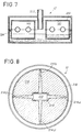
- FIG. 8 a particular embodiment of the cassette 10 is illustrated, comprising a resistor preferably of ceramic type 210, inserted, by crimping or fitting, for example, in the center of a diffuser 212 made of a material conducting heat such as aluminum for example and provided with at least three fins 214a to 214d placed on either side of its center.
- a porous body 216 is inserted under pressure (compressed) between each fin and held in place by a perforated circular envelope 218 advantageously constituted by a simple grid.
- FIG 9 attempts to illustrate very schematically a method for de-soiling a cassette to allow its reuse.
- pumping means for example the water supply pump 50
- a water tank for example the tank external 60
- the pump draws water from the reservoir and introduces it into the cassette where it is heated to a determined temperature lower than its evaporation value but higher at 60 ° C, in order to retain tartar and insoluble minerals.
- the water can then be extracted through the steam outlet orifice 30.
Landscapes
- Engineering & Computer Science (AREA)
- Mechanical Engineering (AREA)
- Sustainable Development (AREA)
- Sustainable Energy (AREA)
- Physics & Mathematics (AREA)
- Thermal Sciences (AREA)
- Life Sciences & Earth Sciences (AREA)
- General Engineering & Computer Science (AREA)
- Engine Equipment That Uses Special Cycles (AREA)
- Air Humidification (AREA)
- Thermotherapy And Cooling Therapy Devices (AREA)
- Devices For Medical Bathing And Washing (AREA)
- Apparatus For Disinfection Or Sterilisation (AREA)
- Finger-Pressure Massage (AREA)
- Resistance Heating (AREA)
Applications Claiming Priority (2)
| Application Number | Priority Date | Filing Date | Title |
|---|---|---|---|
| FR9313840A FR2712668B1 (fr) | 1993-11-19 | 1993-11-19 | Générateur de vapeur rechargeable. |
| FR9313840 | 1993-11-19 |
Publications (2)
| Publication Number | Publication Date |
|---|---|
| EP0654635A1 true EP0654635A1 (de) | 1995-05-24 |
| EP0654635B1 EP0654635B1 (de) | 1998-06-17 |
Family
ID=9453034
Family Applications (1)
| Application Number | Title | Priority Date | Filing Date |
|---|---|---|---|
| EP94402422A Expired - Lifetime EP0654635B1 (de) | 1993-11-19 | 1994-10-27 | Wiederaufladbarer Dampferzeuger |
Country Status (7)
| Country | Link |
|---|---|
| US (1) | US5602958A (de) |
| EP (1) | EP0654635B1 (de) |
| JP (1) | JPH07198104A (de) |
| AT (1) | ATE167562T1 (de) |
| DE (1) | DE69411127T2 (de) |
| ES (1) | ES2117231T3 (de) |
| FR (1) | FR2712668B1 (de) |
Cited By (1)
| Publication number | Priority date | Publication date | Assignee | Title |
|---|---|---|---|---|
| EP0947767A3 (de) * | 1998-04-02 | 2001-01-31 | Carel S.r.l. | Vorrichtung zur Detektion der Kesselsteindicke auf Widerstandselementen von elektrischen Dampferzeugern |
Families Citing this family (13)
| Publication number | Priority date | Publication date | Assignee | Title |
|---|---|---|---|---|
| DE29504734U1 (de) * | 1995-03-20 | 1996-07-18 | Perycut-Chemie AG, Zürich | Verdampfervorrichtung |
| US5945094A (en) * | 1997-04-14 | 1999-08-31 | S. C. Johnson & Son, Inc. | Disposable plug-in dispenser for use with air freshener and the like |
| US5903710A (en) * | 1997-04-14 | 1999-05-11 | S. C. Johnson & Son, Inc. | Air freshener dispenser device with disposable heat-promoted cartridge |
| DE29822527U1 (de) * | 1998-12-17 | 1999-02-11 | Tsai, Sam, Taipeh/T'ai-pei | Multifunktioneller, elektrischer Dampfreiniger |
| US6169852B1 (en) | 1999-04-20 | 2001-01-02 | The Hong Kong University Of Science & Technology | Rapid vapor generator |
| DE10234625B4 (de) * | 2002-07-29 | 2005-02-24 | Rational Ag | Dampferzeuger mit Reaktor zur Kalkkristallkeimbildung |
| JP4573250B2 (ja) * | 2004-11-10 | 2010-11-04 | コーニンクレッカ フィリップス エレクトロニクス エヌ ヴィ | 単線を用い双方向通信を実行する方法及び装置 |
| US7219628B1 (en) | 2004-11-17 | 2007-05-22 | Texaco Inc. | Vaporizer and methods relating to same |
| WO2006070317A1 (en) * | 2004-12-28 | 2006-07-06 | Koninklijke Philips Electronics N.V. | Measures for keeping a degree of contamination of a steam generator including its contents below a predetermined maximum |
| PL1861539T3 (pl) | 2005-03-25 | 2015-08-31 | Lg Electronics Inc | Maszyna pralnicza oraz sposób jej sterowania |
| KR101215347B1 (ko) * | 2005-08-29 | 2012-12-26 | 엘지전자 주식회사 | 드럼세탁기의 스팀발생장치 및 그 제어방법 |
| KR100774181B1 (ko) * | 2005-09-01 | 2007-11-07 | 엘지전자 주식회사 | 증기발생장치 |
| US20190308228A1 (en) * | 2018-04-06 | 2019-10-10 | A.J.Antines & Co. | System and method for cleaning steam generators |
Citations (3)
| Publication number | Priority date | Publication date | Assignee | Title |
|---|---|---|---|---|
| EP0240387A1 (de) * | 1986-03-03 | 1987-10-07 | Association Pour La Recherche Et Le Developpement Des Methodes Et Processus Industriels (Armines) | Verfahren und Vorrichtung zur raschen Verdampfung einer Flüssigkeit |
| EP0317444A1 (de) * | 1987-11-19 | 1989-05-24 | Association Pour La Recherche Et Le Developpement Des Methodes Et Processus Industriels (Armines) | Dampferzeuger |
| EP0323328A1 (de) * | 1987-12-24 | 1989-07-05 | Association Pour La Recherche Et Le Developpement Des Methodes Et Processus Industriels (Armines) | Tragbare elektrische Vorrichtung zur Dampferzeugung, insbesondere zum Entfernen von Wandbekleidung |
-
1993
- 1993-11-19 FR FR9313840A patent/FR2712668B1/fr not_active Expired - Fee Related
-
1994
- 1994-10-27 AT AT94402422T patent/ATE167562T1/de not_active IP Right Cessation
- 1994-10-27 EP EP94402422A patent/EP0654635B1/de not_active Expired - Lifetime
- 1994-10-27 DE DE69411127T patent/DE69411127T2/de not_active Expired - Fee Related
- 1994-10-27 ES ES94402422T patent/ES2117231T3/es not_active Expired - Lifetime
- 1994-11-10 US US08/337,998 patent/US5602958A/en not_active Expired - Fee Related
- 1994-11-15 JP JP6280841A patent/JPH07198104A/ja active Pending
Patent Citations (3)
| Publication number | Priority date | Publication date | Assignee | Title |
|---|---|---|---|---|
| EP0240387A1 (de) * | 1986-03-03 | 1987-10-07 | Association Pour La Recherche Et Le Developpement Des Methodes Et Processus Industriels (Armines) | Verfahren und Vorrichtung zur raschen Verdampfung einer Flüssigkeit |
| EP0317444A1 (de) * | 1987-11-19 | 1989-05-24 | Association Pour La Recherche Et Le Developpement Des Methodes Et Processus Industriels (Armines) | Dampferzeuger |
| EP0323328A1 (de) * | 1987-12-24 | 1989-07-05 | Association Pour La Recherche Et Le Developpement Des Methodes Et Processus Industriels (Armines) | Tragbare elektrische Vorrichtung zur Dampferzeugung, insbesondere zum Entfernen von Wandbekleidung |
Cited By (1)
| Publication number | Priority date | Publication date | Assignee | Title |
|---|---|---|---|---|
| EP0947767A3 (de) * | 1998-04-02 | 2001-01-31 | Carel S.r.l. | Vorrichtung zur Detektion der Kesselsteindicke auf Widerstandselementen von elektrischen Dampferzeugern |
Also Published As
| Publication number | Publication date |
|---|---|
| ES2117231T3 (es) | 1998-08-01 |
| ATE167562T1 (de) | 1998-07-15 |
| JPH07198104A (ja) | 1995-08-01 |
| DE69411127D1 (de) | 1998-07-23 |
| EP0654635B1 (de) | 1998-06-17 |
| FR2712668B1 (fr) | 1996-02-09 |
| FR2712668A1 (fr) | 1995-05-24 |
| US5602958A (en) | 1997-02-11 |
| DE69411127T2 (de) | 1998-11-19 |
Similar Documents
| Publication | Publication Date | Title |
|---|---|---|
| EP0654635B1 (de) | Wiederaufladbarer Dampferzeuger | |
| EP3064640B1 (de) | Elektrohaushaltsgerät zum bügeln, das einen behälter umfasst, der einen wasserenthärter und einen dampfverteilungskreislauf mit einem filter umfasst | |
| FR3060027A1 (fr) | Appareil de defroissage a la vapeur | |
| FR2915344A1 (fr) | Dispositif de chauffage de fluide et appareil d'epuration de gaz d'echappement, equipe d'un tel dispositif. | |
| EP0298872B1 (de) | Verfahren und Vorrichtung zur Verteilung eines primären Volumens von Flüssigkeiten in eine bestimmte Zahl von sekundären Volumen, die ein bestimmtes Verhältnis zueinander haben | |
| FR2688807A1 (fr) | Appareil a repasser a vapeur muni d'un dispositif de detection et de suppression de tartre. | |
| FR2611867A1 (fr) | Rechauffeur tubulaire a ailettes | |
| FR3021198A1 (fr) | Dispositif et procede de production et de distribution de liquide en ebullition et appareil de preparation de boisson equipe d'un tel dispositif | |
| EP1839762A1 (de) | Optimiertes Sprühverfahren für Flüssigkeiten und Vorrichtung zum Sprühen von Flüssigkeiten für die Umsetzung dieses Verfahrens | |
| FR2981252A1 (fr) | Appareil de coiffure a vapeur a pompe commandee | |
| BE1019090A3 (fr) | Dispositif pour l'alimentation en combustible d'une installation de production d'energie d'un navire. | |
| FR2680393A1 (fr) | Procede et dispositif de commande d'une installation de pompage. | |
| EP3643831B1 (de) | Verfahren zur reinigung eines bügeleisens, das mit einem hohlraum zur sammlung von kalkablagerungen ausgestattet ist | |
| FR2738661A1 (fr) | Dispositif et procede de recuperation et de refroidissement du coeur en fusion d'un reacteur nucleaire | |
| EP0088649B1 (de) | Verfahren und Vorrichtung zur Adsorption von Wasserstoff mittels eines Adsorbermetalls und zur Freisetzung des adsorbierten Wasserstoffes | |
| CH618292A5 (de) | ||
| FR2708347A1 (fr) | Chambre de mesure, notamment pour le contrôle de l'eau d'une piscine. | |
| FR3067725A1 (fr) | Appareil pour le traitement du linge comportant un generateur de vapeur a vaporisation instantanee | |
| EP2916965B1 (de) | Mit gespeicherter obsoleszenz ausgetattete kartusche zur erzeugung und ausgabe eines aerosols und sprühvorrichtung mit einer solchen kartusche | |
| FR2645624A1 (fr) | Generateur de vapeur d'eau, et son application a un appareil pour fondre la cire d'abeille | |
| EP0597748B1 (de) | Schnelldampferzeuger | |
| FR2621083A1 (fr) | Pompe immergee de prelevement de liquide dans une conduite, notamment une conduite de rejet en eau profonde d'eaux de refroidissement de centrale nucleaire | |
| FR2764821A1 (fr) | Dispositif de dosage par introduction dans un liquide d'un reactif sous forme de galets | |
| FR2485363A1 (fr) | Dispositif pour regenerer l'echangeur d'ions d'une machine a laver la vaisselle | |
| FR2691233A1 (fr) | Générateur de vapeur à réponse instantanée. |
Legal Events
| Date | Code | Title | Description |
|---|---|---|---|
| PUAI | Public reference made under article 153(3) epc to a published international application that has entered the european phase |
Free format text: ORIGINAL CODE: 0009012 |
|
| AK | Designated contracting states |
Kind code of ref document: A1 Designated state(s): AT BE CH DE DK ES FR GB GR IE IT LI LU NL PT SE |
|
| 17P | Request for examination filed |
Effective date: 19950830 |
|
| 17Q | First examination report despatched |
Effective date: 19961017 |
|
| GRAG | Despatch of communication of intention to grant |
Free format text: ORIGINAL CODE: EPIDOS AGRA |
|
| GRAG | Despatch of communication of intention to grant |
Free format text: ORIGINAL CODE: EPIDOS AGRA |
|
| GRAH | Despatch of communication of intention to grant a patent |
Free format text: ORIGINAL CODE: EPIDOS IGRA |
|
| GRAH | Despatch of communication of intention to grant a patent |
Free format text: ORIGINAL CODE: EPIDOS IGRA |
|
| GRAA | (expected) grant |
Free format text: ORIGINAL CODE: 0009210 |
|
| AK | Designated contracting states |
Kind code of ref document: B1 Designated state(s): AT BE CH DE DK ES FR GB GR IE IT LI LU NL PT SE |
|
| PG25 | Lapsed in a contracting state [announced via postgrant information from national office to epo] |
Ref country code: GR Free format text: LAPSE BECAUSE OF FAILURE TO SUBMIT A TRANSLATION OF THE DESCRIPTION OR TO PAY THE FEE WITHIN THE PRESCRIBED TIME-LIMIT Effective date: 19980617 Ref country code: AT Free format text: LAPSE BECAUSE OF FAILURE TO SUBMIT A TRANSLATION OF THE DESCRIPTION OR TO PAY THE FEE WITHIN THE PRESCRIBED TIME-LIMIT Effective date: 19980617 |
|
| REF | Corresponds to: |
Ref document number: 167562 Country of ref document: AT Date of ref document: 19980715 Kind code of ref document: T |
|
| REG | Reference to a national code |
Ref country code: CH Ref legal event code: EP |
|
| GBT | Gb: translation of ep patent filed (gb section 77(6)(a)/1977) |
Effective date: 19980619 |
|
| REF | Corresponds to: |
Ref document number: 69411127 Country of ref document: DE Date of ref document: 19980723 |
|
| REG | Reference to a national code |
Ref country code: CH Ref legal event code: NV Representative=s name: BOVARD AG PATENTANWAELTE |
|
| REG | Reference to a national code |
Ref country code: ES Ref legal event code: FG2A Ref document number: 2117231 Country of ref document: ES Kind code of ref document: T3 |
|
| ITF | It: translation for a ep patent filed | ||
| PG25 | Lapsed in a contracting state [announced via postgrant information from national office to epo] |
Ref country code: SE Free format text: LAPSE BECAUSE OF FAILURE TO SUBMIT A TRANSLATION OF THE DESCRIPTION OR TO PAY THE FEE WITHIN THE PRESCRIBED TIME-LIMIT Effective date: 19980917 Ref country code: PT Free format text: LAPSE BECAUSE OF FAILURE TO SUBMIT A TRANSLATION OF THE DESCRIPTION OR TO PAY THE FEE WITHIN THE PRESCRIBED TIME-LIMIT Effective date: 19980917 Ref country code: DK Free format text: LAPSE BECAUSE OF FAILURE TO SUBMIT A TRANSLATION OF THE DESCRIPTION OR TO PAY THE FEE WITHIN THE PRESCRIBED TIME-LIMIT Effective date: 19980917 |
|
| REG | Reference to a national code |
Ref country code: IE Ref legal event code: FG4D Free format text: FRENCH |
|
| PG25 | Lapsed in a contracting state [announced via postgrant information from national office to epo] |
Ref country code: LU Free format text: LAPSE BECAUSE OF NON-PAYMENT OF DUE FEES Effective date: 19981027 |
|
| PG25 | Lapsed in a contracting state [announced via postgrant information from national office to epo] |
Ref country code: BE Free format text: LAPSE BECAUSE OF NON-PAYMENT OF DUE FEES Effective date: 19981031 |
|
| PG25 | Lapsed in a contracting state [announced via postgrant information from national office to epo] |
Ref country code: IE Free format text: LAPSE BECAUSE OF NON-PAYMENT OF DUE FEES Effective date: 19990219 |
|
| REG | Reference to a national code |
Ref country code: IE Ref legal event code: FD4D |
|
| PLBE | No opposition filed within time limit |
Free format text: ORIGINAL CODE: 0009261 |
|
| STAA | Information on the status of an ep patent application or granted ep patent |
Free format text: STATUS: NO OPPOSITION FILED WITHIN TIME LIMIT |
|
| BERE | Be: lapsed |
Owner name: S.A. SUPERBA Effective date: 19981031 |
|
| 26N | No opposition filed | ||
| REG | Reference to a national code |
Ref country code: FR Ref legal event code: ST |
|
| REG | Reference to a national code |
Ref country code: FR Ref legal event code: RN |
|
| REG | Reference to a national code |
Ref country code: FR Ref legal event code: RN |
|
| PGFP | Annual fee paid to national office [announced via postgrant information from national office to epo] |
Ref country code: NL Payment date: 20000918 Year of fee payment: 7 |
|
| PGFP | Annual fee paid to national office [announced via postgrant information from national office to epo] |
Ref country code: ES Payment date: 20001016 Year of fee payment: 7 |
|
| PGFP | Annual fee paid to national office [announced via postgrant information from national office to epo] |
Ref country code: CH Payment date: 20001018 Year of fee payment: 7 |
|
| REG | Reference to a national code |
Ref country code: FR Ref legal event code: TP |
|
| PG25 | Lapsed in a contracting state [announced via postgrant information from national office to epo] |
Ref country code: ES Free format text: LAPSE BECAUSE OF NON-PAYMENT OF DUE FEES Effective date: 20011028 |
|
| PG25 | Lapsed in a contracting state [announced via postgrant information from national office to epo] |
Ref country code: LI Free format text: LAPSE BECAUSE OF NON-PAYMENT OF DUE FEES Effective date: 20011031 Ref country code: CH Free format text: LAPSE BECAUSE OF NON-PAYMENT OF DUE FEES Effective date: 20011031 |
|
| REG | Reference to a national code |
Ref country code: GB Ref legal event code: IF02 |
|
| PG25 | Lapsed in a contracting state [announced via postgrant information from national office to epo] |
Ref country code: NL Free format text: LAPSE BECAUSE OF NON-PAYMENT OF DUE FEES Effective date: 20020501 |
|
| REG | Reference to a national code |
Ref country code: CH Ref legal event code: PL |
|
| NLV4 | Nl: lapsed or anulled due to non-payment of the annual fee |
Effective date: 20020501 |
|
| REG | Reference to a national code |
Ref country code: ES Ref legal event code: FD2A Effective date: 20021113 |
|
| PGFP | Annual fee paid to national office [announced via postgrant information from national office to epo] |
Ref country code: DE Payment date: 20061009 Year of fee payment: 13 |
|
| PGFP | Annual fee paid to national office [announced via postgrant information from national office to epo] |
Ref country code: GB Payment date: 20061010 Year of fee payment: 13 |
|
| PGFP | Annual fee paid to national office [announced via postgrant information from national office to epo] |
Ref country code: IT Payment date: 20061031 Year of fee payment: 13 Ref country code: FR Payment date: 20061031 Year of fee payment: 13 |
|
| GBPC | Gb: european patent ceased through non-payment of renewal fee |
Effective date: 20071027 |
|
| PG25 | Lapsed in a contracting state [announced via postgrant information from national office to epo] |
Ref country code: DE Free format text: LAPSE BECAUSE OF NON-PAYMENT OF DUE FEES Effective date: 20080501 |
|
| REG | Reference to a national code |
Ref country code: FR Ref legal event code: ST Effective date: 20080630 |
|
| PG25 | Lapsed in a contracting state [announced via postgrant information from national office to epo] |
Ref country code: GB Free format text: LAPSE BECAUSE OF NON-PAYMENT OF DUE FEES Effective date: 20071027 |
|
| PG25 | Lapsed in a contracting state [announced via postgrant information from national office to epo] |
Ref country code: FR Free format text: LAPSE BECAUSE OF NON-PAYMENT OF DUE FEES Effective date: 20071031 |
|
| PG25 | Lapsed in a contracting state [announced via postgrant information from national office to epo] |
Ref country code: IT Free format text: LAPSE BECAUSE OF NON-PAYMENT OF DUE FEES Effective date: 20071027 |