EP2915178B1 - Device for generating a reliable low-impedance electric short-circuit irrespectively of the operating voltage - Google Patents
Device for generating a reliable low-impedance electric short-circuit irrespectively of the operating voltage Download PDFInfo
- Publication number
- EP2915178B1 EP2915178B1 EP13752905.3A EP13752905A EP2915178B1 EP 2915178 B1 EP2915178 B1 EP 2915178B1 EP 13752905 A EP13752905 A EP 13752905A EP 2915178 B1 EP2915178 B1 EP 2915178B1
- Authority
- EP
- European Patent Office
- Prior art keywords
- film
- exothermic
- mass
- connection parts
- short
- Prior art date
- Legal status (The legal status is an assumption and is not a legal conclusion. Google has not performed a legal analysis and makes no representation as to the accuracy of the status listed.)
- Not-in-force
Links
Images

Classifications
-
- H—ELECTRICITY
- H01—ELECTRIC ELEMENTS
- H01H—ELECTRIC SWITCHES; RELAYS; SELECTORS; EMERGENCY PROTECTIVE DEVICES
- H01H39/00—Switching devices actuated by an explosion produced within the device and initiated by an electric current
- H01H39/006—Opening by severing a conductor
-
- H—ELECTRICITY
- H01—ELECTRIC ELEMENTS
- H01T—SPARK GAPS; OVERVOLTAGE ARRESTERS USING SPARK GAPS; SPARKING PLUGS; CORONA DEVICES; GENERATING IONS TO BE INTRODUCED INTO NON-ENCLOSED GASES
- H01T1/00—Details of spark gaps
- H01T1/14—Means structurally associated with spark gap for protecting it against overload or for disconnecting it in case of failure
-
- H—ELECTRICITY
- H01—ELECTRIC ELEMENTS
- H01T—SPARK GAPS; OVERVOLTAGE ARRESTERS USING SPARK GAPS; SPARKING PLUGS; CORONA DEVICES; GENERATING IONS TO BE INTRODUCED INTO NON-ENCLOSED GASES
- H01T4/00—Overvoltage arresters using spark gaps
- H01T4/02—Details
Definitions
- the invention relates to a device for operating voltage-independent generating a safe, low-resistance electrical short circuit, comprising two electrical, in particular plate-shaped connecting parts, which lead a different potential, wherein between the connection parts an insulation gap is formed and the desired short circuit via a, at least partially, or a penetration Destroy the isolation route is realized, according to the preamble of claim 1.
- a device for operating voltage-independent generating a safe, low-resistance electrical short circuit comprising two electrical, in particular plate-shaped connecting parts, which lead a different potential, wherein between the connection parts an insulation gap is formed and the desired short circuit via a, at least partially, or a penetration Destroy the isolation route is realized, according to the preamble of claim 1.
- Such a device is besistentlus from the document FR 2 884 602 A1 known.
- the realization of a targeted electrical short circuit is a common method for a variety of electrical devices to ensure a safe switching state.
- the measure "short-circuit" is an agent that is generally initiated only when normal and normal operation of electrical appliances due to overloading or aging no longer exists.
- the possibilities and the expense of realizing such an additional measure outside basic functions of the electrical devices are limited per se.
- a targeted short circuit be available even if no or only an undefined network energy is available. The requirements regarding the safety and effectiveness of the action of a targeted short circuit are therefore very high.
- the heating is used to trigger the short-circuit.
- Usual are here, for example, spring-biased movable contacts, which are released by the heating of solder or wax.
- the time to reach the short circuit state can be significantly reduced.
- low cost semiconductors in many cases do not have sufficient current carrying capacity.
- the realized short circuit is also not low-impedance and it is the effort to control and protect the semiconductor and their EMC-safe use in many applications high.
- overvoltage protection protective devices are furthermore known in which e.g. heating-expanding materials are used to cause movement of contacts.
- the targeted control of such materials, for example with an additional heating element is known.
- the short circuit should be active, that is, it can be deliberately brought about with the help of an external or internal activation, and on the other hand it can also be passive, independently of achieving at least one defined condition.
- the active control is to be realized by as diverse as possible individual criteria, but also by ORs of these criteria.
- the short-circuit device to be created should manage without expensive mechanical drive and react very quickly, so that reaction times are similar to those of electronic switching elements.
- the short circuit to be realized should also enable a selective disconnection of overcurrent protection devices and be suitable for the conduction of continuous currents. Accordingly, it is desired that the device provide a low resistance galvanic connection suitable for persistent currents.
- the parts required for the short circuit and the control should be executable as a ready-to-connect supplementary unit.
- the basic idea of the invention is to distinguish between two, e.g. plate-shaped parts which lead to a different electrical potential, at least in each case an insulating film and an exothermic mass, which is preferably also executable as a film to arrange.
- the connecting parts with different potential have a distance of a few 10 microns to a few 100 microns.
- the mentioned exothermic mass is preferably close to ground or at ground potential.
- the mass can now be activated by a voltage pulse, a current pulse, by a mechanical shock or pressure or an intense light pulse or even during or by electrical discharge and diversion processes.
- the exothermic mass is quasi passively subject to activation even when reaching a defined temperature.
- the reaction of the exothermic mass leads to melting or to a deformation of the insulating film forming the insulating film within a very short time, whereby the potential separation is canceled and a short circuit between the floating parts can be produced.
- the realization of the short circuit can be supported by additional design measures and variants described in the embodiments.
- connection parts are arranged closely adjacent to the isolation path.
- the insulation gap can, as already stated, be formed as an insulation film, but also as a film-like coating.
- the aforementioned exothermic mass which releases its exothermic energy when energized and leads to melting or destroying or deforming the insulation section, so that the potential separation between the connection parts is canceled and enters the desired unique short circuit case.
- At least one of the connecting parts can be under mechanical prestress, so that when the insulation section is destroyed or deformed, the connecting parts come into contact with each other via a mechanical movement that then occurs.
- this can be a sandwich arrangement with the insulation gap, which in turn can also be formed by a film.
- the exothermic mass is designed and dimensioned such that sufficient heat is released within a period of about 1 to 10 ms in order to melt or significantly deform the insulation film or insulation layer.
- the exothermic mass is integrated in one or both of the connecting parts.
- the short-circuiting device therefore consists of two e.g. plate-shaped electrically conductive parts having generally different potential, between which at least one respective insulating film and an exothermic mass, which is preferably also formed as a film is brought.
- the two electrically conductive parts with generally different potential can be connection or connection elements of the device to be protected by short circuits or else a component of a connection-ready supplementary unit "short-circuiter".
- the electrically conductive parts have a distance of a few 10 microns to a few 100 microns.
- One or both parts can be under a mechanical preload, which in the simplest case is created by the joining of the parts and the material properties.
- the thickness and the material properties of the electrical insulating film determine the maximum rated voltage and the transient dielectric strength of the short-circuiting device. In addition to the breakdown properties of the film, of course, the flashover properties and the influences of the corresponding environmental conditions must be observed. However, the operating voltage range can be easily selected from the range of the safety extra-low voltage to the low-voltage range without any functional limitations.
- the exothermic mass develops after its active or passive activation immediately at the activation site within a period of less than 1 ms so much heat that the insulation film melts.
- the exothermic mass in film form and with active ignition at only one point of the mass, the exothermic reaction within the film continues at high speed, so that even with large required contact surfaces generally one activation point is sufficient. Due to the rapid release of the heat, the influence of the heat capacity and heat conduction of the electrically conductive connection parts (short-circuit contacts) is almost negligible.
- the energy input can be considered almost adiabatic and the amount of energy of the exothermic mass must be measured only to melt the film. This allows a very simple integration of the device in numerous existing devices to be protected, since the space required in the usual tolerance range of the items of technical equipment.
- the exothermic mass is preferably close to ground or at ground potential.
- the mass or film can also be integrated in an electrically conductive connection part, so that only the insulation film determines the spacing of the conductive parts.
- the film itself may be electrically conductive and similarly thin designed as the insulating film, so that the cost of introducing the exothermic mass is negligible.
- the insulating film and the exothermic film can also be designed as a composite material in sandwich form with a suitable design of the electrically conductive parts.
- the insulating film can also be surrounded on both sides by an exothermically reacting mass (foil). This intensifies the melting process of the insulation film.
- the material of the molten insulating film can create one or more areas in which the melt residues can be urged to make the shortest possible low impedance.
- the cavities or channels can be integrated into the electrically conductive connection plates. In the case of an electrically conductive exothermic mass, it may also be designed to accommodate or specifically displace the melt.
- the targeted influence on the melt of the insulating material is useful even at low operating or residual stresses in the fault state, eg in arcs, so that even with the low film thicknesses no minimum air or sliding distance remains despite molten film.
- the pure displacement effect of the melt of the insulating film is supported by the heat of reaction, the first current flow, possibly with minimal discharge formation, and by a minimum bias of the connecting parts.
- the reaction area also easily melting metals (low heat conduction, low heat capacity, low melting temperature), for example, as a coating of the films, the exothermic film or the connecting parts are used. The resulting molten metal bridges the minimum gap after melting the insulation film.
- the exothermic reaction can also be used to accelerate thermal processes for melting or moving parts.
- the presented arrangement allows the bi-functional use of the exothermic reaction for the preferred realization of a short circuit.
- the reaction can be triggered on the one hand purposefully and independently of the environmental conditions of the film or the device, for example by a remote control.
- influence or reference variables of the immediate surroundings of the film or signal quantities of the device can be used directly or indirectly. The application possibilities are therefore almost unlimited.
- the purely passive reaction of the film upon reaching a limit temperature can be used, for example, in components or devices in which higher temperatures lead to overloading or a fire hazard. This feature has a redundant effect in many applications where active activation fails.
- the film can be placed in direct thermal contact with the component at risk of overload, or the heat via a thermal coupling.
- the passive thermal reaction of the film can also be used via an additional heating element. Due to the very low heat capacity and low heat conduction, the exothermic reaction can be achieved only with a nearly selective energy coupling and low power. The required power corresponds to only a fraction of thermally sensitive enamel, such as solders, waxes etc.
- the mass can be activated for example by a voltage pulse, a current flow, by mechanical impact, an intense light pulse or electric discharge or charge processes.
- a voltage pulse can be generated in the simplest case by a defined flashover distance or by means of discrete components which respond to overvoltages.
- a current flow can be generated by the targeted electronic or mechanical connection, for example, the supply voltage of the device or an available auxiliary voltage source generated in the exothermic mass. For this purpose, the transfer of a capacity, a battery or the like is also sufficient.
- a laser pulse or a strong mechanical impulse can be used for example directly by a firing pin or by strong vibration.
- These options therefore allow the use of a simple mechanical or electronic shutter, for example by applying the mass with a current flow or a charge, which may be remotely operated.
- Components such as thermal switches, NTC, PTC, GDT's, varistors, Hall sensors, piezo elements, etc., which can react to internal load variables defined, are connected internally or deliberately switched from the outside.
- Also suitable for igniting the mass is the thermal overload of current bridges, for example, fusible conductors, which can be used both for thermal heating or for spark formation.
- the ignition of the mass can also be done by the destruction of the components themselves and the device can be spent by the realization of a defined short circuit in a safe state.
- the rollover or destruction of electrical or electronic components generally generates sparks, arcs or hot ionized gases.
- the accompanying phenomena could be used directly for an activation of the mass.
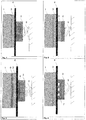
- Fig. 1 a principle basic arrangement for the realization of a short circuit is shown.
- the plate-shaped connection parts 1 and 2 can be existing electrically conductive parts of the device to be protected or also additional parts which are inserted into the device.
- the essential components represent the exothermic mass, for example in film form 3 and the insulating film 4. Both parts each have a thickness of only a few 10 microns.
- the part shown as a spring element 5 is not mandatory. Due to the short distances, a clamping connection of the parts or even the intrinsic elasticity of the parts is generally sufficient.
- the distance between the connecting parts 1 and 2 can be reduced to the thickness of the insulating film 4.
- the insulation film 4 and the connection parts 2 are designed so that the electrical voltage resistance between the connection parts 1 and 2 corresponds to the electrical breakdown voltage of the insulation film.
- Fig. 1 is realized, for example, only by the appropriate design of the supernatant of the insulation film, so a corresponding dimensioning of the sliding distance of the film 4 of parts 1 to Part 2.
- all the usual measures to increase the dielectric strength between the parts 1 and 2 can be used.
- the Fig. 1 limited to the passive triggering of the exothermic reaction, in the case of heating the film 3 to the reaction temperature. This heating could be done for example by thermal conduction through the connection part 1. Upon reaching the reaction temperature, the Foil 3 within a few microseconds to ms release a sufficient amount of energy to melt the insulating film 4 in the contact area. As a result, the electrical insulation strength of the film between the parts 1 and 2 is repealed and there is a short circuit between the two connection parts. In the arrangement accordingly Fig. 1 the exothermic mass 3 is electrically conductive both before the reaction and after the reaction. However, this is not absolutely necessary due to the small dimensions of the film 3.
- the residual stress of the parts is sufficient to realize a low-resistance metallic connection of the parts 1 and 2 with sufficient current carrying capacity.
- the melt residues of the film 4 are generally displaced from the contact area by the applied pressure of the clamping connection.
- the distance between the electrically conductive parts 1 and 2 is also independent of the properties of the mass. 3
- Fig. 2 shows an arrangement in which the insulating film 4 is disposed between two sheets of exothermic mass 3.
- the insulating film can be supplied with the required heat of fusion from both sides.
- a film 3 may, for. B. are used exclusively for passive triggering by heating and the other film can be actively controlled. If required, both sides can also be used for passive monitoring at the same or different trip temperature.
- both sides can also be used for passive monitoring at the same or different trip temperature.
- stronger insulation films can be destroyed and that the destruction of the insulation layer can be accelerated.
- such a high radiation intensity is produced that the film is automatically activated on the opposite side of the insulating film, for example in the case of optically transparent insulation films 4.
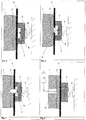
- Fig. 3 an arrangement is shown in which the connecting parts or the film 3 is additionally coated with an electrically conductive material having a low melting temperature 6, for example low-temperature solder.
- the solder can also be added as an additional film.
- This additional material can realize several functions.
- the material can serve as a defined heat transfer barrier to the terminals to the optimally transfer resulting heat of reaction to the insulation film and the additional material.
- the resulting melt of the low-melting material can be used for rapid and large-scale bridging of the isolation gap.
- the melt can also serve for permanent soldering of the terminals 1 and 2 and thus take over a mechanical function after the reaction to realize a permanent short circuit in addition to the electrical function.
- channels, grooves or cavities in one or both terminals can be used in particular for larger required contact surfaces between the terminals for receiving melt residues of the insulating film or for their targeted displacement from the contact area.
- Fig. 4 shows in the terminal 2, for example, such an arrangement of cavities / channels 7. It should be noted, however, that the real contact surface remains sufficiently large.
- Fig. 5 a similar arrangement with a larger cavity 7 is shown.
- a mandrel 8 can be mounted in the cavity.
- the material 3 deforms very strongly, causing a kind of deep drawing process of the material into the cavity 7.
- these are already drawn into the cavity before melting and destroyed on the mandrel 8, so that the short circuit is realized even before complete melting of the insulating film and also before the displacement of the remainder of the film.
- Fig. 6 shows a similar arrangement in which the insulating film has a suitable recess 9 in the region of the cavity, whereby a movement of the insulating film 4 by the exothermic film 3 in the reaction is not necessary.
- the short circuit between the electrically conductive exothermic mass 3 is realized by the contact of the mandrel 8 or also directly of the terminal 2 after the deformation of the film 3.
- Fig. 7 shows the arrangement accordingly Fig. 6 after the exothermic reaction and the deformation of the part 3.
- Fig. 8 shows a possible basic arrangement, wherein the activation point takes place relatively centrally on the film 3. This ensures, in particular for relatively large areas, that the necessary heat of fusion for the film 4 is available almost at the same time due to the internal reaction speed within the film at the two edge regions.
- the film 3 can also be activated at an edge region or at several points. The activation of the film 3 takes place in the arrangement via an electrically conductive connection line 11.
- This line can be soldered to the film 3, clamped or even just hang up. There may also be a minimum distance between the conduit 11 and the part 3.
- the cable cross-section can be very small ⁇ 1mm 2 .
- the requirements of the electrical insulation of the line 11 with respect to the connection part 1 is negligible, as long as the contact or the distance to the part 3 is guaranteed or less.
- the component 10 in the electrical connection line 11 may be located within the device to be protected or outside.
- the component 10 itself may be a sensor or a controllable element which responds to requirements within the device to be protected or external conditions or signals.
- the component 10 may be an electrical switch or mechanical switch. By its operation, a potential is applied to the film 3, which differs from that of the film 3 and the terminal 1, whereby a charge compensation takes place.
- the film 3 is activated by the current flow or the discharge (sparking by current flow or flashover) in the contact area Part 3 and Part 11.
- the part 10 may also be designed as NTC, PTC, GDT, varistor, Zener diode, thermal switch, piezoelectric elements, etc. By choosing the sensor a variety of internal or external variables are used for activation. Due to the very low energy requirement for activation, also wireless methods (transmitter-receiver) can be used without restrictions.
- the additional element 12 may be designed, for example, as an impedance, spark gap or else as a fused wire with a defined I 2 t value. This allows, regardless of the amount of charge available, a defined generation of sparks, which cause the reaction of the film 3 very effectively and very quickly. The speed of triggering the film can be significantly increased compared to the heating of the film by a current flow without sparking.
- laser or firing pin act analogously to the fuse on the film 3 and trigger targeted.
- FIG. 11 show arrangements with a housing, which are suitable for a subsequent attachment of the short-circuiter to a device to be protected / component.
- Fig. 10 will be out Fig. 1 known arrangement in a housing 13 made of metal.
- the connection element 1 is directly connected to the housing.
- the housing 13 can also be used as a connection element 1 itself.
- the terminal 2 is insulated from the housing 13 led to the outside.
- the bushing 14 serves for insulation and the part 15 for the outer connection.
- a further connection 23 can be guided through the housing 13, which can be used to actively activate the film 13 with an outer component 10.
- the passive activation of the film 3 takes place by the heat transfer from the housing or connection 1 to the film 3.
- Fig. 11 shows a similar arrangement, however, the housing 13 is made of insulating material and has two passages for the outer terminals 15, 16 of the connecting elements 1 and 2. The passive heating of the film 3 can take place via the terminal 16. Alternatively, the housing 13 may also have an outwardly directed heat transfer element 24 include. This can be electrically isolated or electrically connected to the connection element 1.
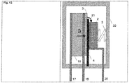
- Fig. 12 and Fig. 13 show an exemplary use of the short-circuiting arrangement with a component to be protected in a common housing.
- the housing has in each case three connections 17, 18, 20, which are all led separately to the outside in a housing made of insulating material 22. This allows separate external wiring of the short-circuiter via the outer terminals.
- the short-circuiting device can also be wired inside the housing, whereby the outer connection 20 would be omitted.
- a surge arrester in particular a varistor 19 was selected to explain the function. It is well known that varistors can become very hot or overturn at the risk of overloading.
- Fig. 12 is a flashover, which is connected to a spark discharge 21, indicated.
- the film 3 is heated directly through the varistor.
- the connection 1 of the short-circuiter can in this case simultaneously be the connection plate 18 of the varistor.
- the insulating film 4 is melted and causes a short circuit between the terminals 18 and 20. If the varistor is bridged by a spark discharge 21, the terminals 18 and 20 are also low-resistance short-circuited after the activation of the film 3 by the flashover, whereby the bursting of the housing 22 due to an open arc can be prevented.
- the insulating film 4 may be cast in the housing 22 to increase the flashover resistance between the terminal 18 and the terminal 2 or 20.
- Fig. 13 shows a similar arrangement as Fig. 12
- the supernatant of the insulating film 4 between the terminal 1 and the film 3 and the terminal 2 is pronounced as a sliding spark gap.
- the spark gap can be dimensioned such that, with a corresponding connection of the terminals 17, 18, 20, an undefined flashover of the varistor between the terminals 17 and 18 is avoided and the foil 3 is ignited immediately to realize a short circuit.
- the endangerment of the housing 22 by the pressure generated in an undefined flashover can be further reduced by this measure.
- GDTs or other voltage-switching elements it is of course also possible to use GDTs or other voltage-switching elements.
- the terms used in the description and in the embodiment of an active or passive activation of the exothermic mass are based on the manner of introducing a corresponding activation energy. Passive mechanisms are to be understood here, which result in the usual use of the device to be protected without specific intervention in the risk of overloading or by the overload itself. This can be the case of a varistor, for example, the heating due to a current load.
- the exothermic mass e.g. designed as a reaction foil ignites it as a result of the passive heat input at its ignition temperature without additional ignition aid.
- the protective mechanism can optionally be triggered against damage to the component to be protected. Under passive activation but also the triggering due to the sparking at an outer rollover of the varistor should be understood, in which case there is already a damage to the actual component and the protective measure is only to mitigate damage, for. to avoid a bursting of a housing.
- Active mechanisms are those that are independent of the state of the components. These can be current, voltage, power of the corresponding component, which should be protected accordingly. However, active mechanisms are also those which can be used outside the passively protected component for triggering.
- the short-circuiting device according to the invention which is used passively to protect an overvoltage protection device, can also be used to extinguish an external arc due to active activation, which would not actuate the short-circuiting device via the passive triggering mechanisms, eg due to the local distance.
- the preferred reaction film used as an exothermic mass should have a small thickness and allow a fast, self-propagating exothermic reaction.
- the film should be both passive and active to their exothermic reaction initiation can be performed, with a pressure to avoid development and primarily to ensure heat development.
- reaction foil e.g. the product Nanofoil (registered trademark) can be used.
- insulation film a known technical insulation film for electrical applications can be applied, which has a high dielectric strength and has a continuous use temperature, which corresponds to the application of the device to be protected.
- PE, PET, PS, PP, PSU, PA6 and PC films with an electrical breakdown strength of> 30 KV / mm are suitable here.
- reaction film as an exothermic mass and the electrical insulation film can be sandwiched, i. also such that reaction films are located on both sides of the insulating film.
Description
Die Erfindung betrifft eine Einrichtung zum betriebsspannungsunabhängigen Erzeugen eines sicheren, niederohmigen elektrischen Kurzschlusses, umfassend zwei elektrische, insbesondere plattenförmige Anschlussteile, welche ein unterschiedliches Potential führen, wobei zwischen den Anschlussteilen eine Isolationsstrecke ausgebildet ist und der gewünschte Kurzschluss über eine, mindestens teilweise, Durchdringung oder ein Zerstören der Isolationsstrecke realisiert ist, gemäß dem Oberbegriffes des Anspruches 1. Eine derartige Einrichtung ist besispielsweise aus der Druckschrift
Anwendung findet diese Methode u.a. bei der Überlastung von elektrischen Bauteilen zur Vermeidung von Überhitzungen oder Bränden, bei der Realisierung definierter Impedanzverhältnisse zur Vermeidung von gefährlichen Spannungen oder zur Gewährleistung definierter Abschaltbedingungen, beispielsweise durch Überstromschutzeinrichtungen oder auch zur Löschung von fehlerhaft entstehenden Lichtbögen.Application finds this method u.a. in the overload of electrical components to prevent overheating or fires, in the realization of defined impedance ratios to avoid dangerous voltages or to ensure defined shutdown conditions, for example by overcurrent protection devices or to delete faulty arcing.
Die Maßnahme "Kurzschluss" ist jedoch ein Mittel, das im Allgemeinen erst dann eingeleitet wird, wenn eine übliche und normale Funktion von elektrischen Geräten infolge einer Überlastung oder Alterung nicht mehr gegeben ist. Die Möglichkeiten und der Aufwand zur Realisierung einer solchen zusätzlichen Maßnahme außerhalb von Grundfunktionen der elektrischen Einrichtungen sind an sich begrenzt. Häufig soll ein gezielter Kurzschluss auch dann erreichbar sein, wenn keine oder nur eine undefinierte Netzenergie mehr verfügbar ist. Die Anforderungen bezüglich der Sicherheit und der Wirksamkeit der Maßnahme eines gezielten Kurzschlusses sind mithin sehr hoch.However, the measure "short-circuit" is an agent that is generally initiated only when normal and normal operation of electrical appliances due to overloading or aging no longer exists. The possibilities and the expense of realizing such an additional measure outside basic functions of the electrical devices are limited per se. Often, a targeted short circuit be available even if no or only an undefined network energy is available. The requirements regarding the safety and effectiveness of the action of a targeted short circuit are therefore very high.
Die Realisierung eines Kurzschlusses zur Herstellung eines sicheren Zustands (Fail-safe) ist ein bekanntes und übliches Verfahren zur Vermeidung größerer Schäden, z.B. bei Überlastgefahr von Bauteilen.The realization of a short circuit to establish a safe state (fail-safe) is a known and common method of avoiding major damage, e.g. in case of overload of components.
Die Methoden des Standes der Technik zur Realisierung eines Kurzschlusses sind recht unterschiedlich, wie auch die damit bezweckte jeweilige Schutzfunktion.The methods of the prior art for the realization of a short circuit are quite different, as well as the respective intended purpose of protection.
Vielfach werden mechanisch betätigte Schalteinrichtungen zur Realisierung eines niederohmigen und dauerstromtragfähigen Kurzschlusses eingesetzt. Diese Schalteinrichtungen benötigen jedoch insbesondere bei dem Wunsch der gezielten Ansteuerung im Allgemeinen eine Hilfsenergie zur Betätigung und sind konstruktiv sehr aufwendig ausgeführt.In many cases, mechanically actuated switching devices are used to realize a low-resistance and permanent current-carrying short circuit. However, these switching devices generally require an auxiliary power for the actuation, in particular in the case of the desired activation, and are of very complex design.
Der Platzbedarf derartiger Einrichtungen ist neben der Spannungsfestigkeit und der Stromtragfähigkeit häufig auch von der Art der Betätigung abhängig. Bei hoher Stromtragfähigkeit ist in vielen Fällen die zu bewegende Masse recht hoch, wodurch die Schließzeit und der Aufwand zur Betätigung steigen.The space requirement of such devices is often dependent on the type of operation in addition to the dielectric strength and current carrying capacity. At high current carrying capacity in many cases, the mass to be moved is quite high, whereby the closing time and the effort to operate increase.
Um diese Betätigungszeiten zu reduzieren, wird häufig weiterer Aufwand für eine beschleunigte Bewegung bis hin zu Antrieben auf der Basis von Sprengkapseln getrieben.In order to reduce these actuation times, further expenditure for an accelerated movement up to drives on the basis of blasting caps is often driven.
Die konzeptionellen und physikalischen Nachteile können trotz vielfältiger Lösungen im Stand der Technik nicht vollständig beseitigt werden.The conceptual and physical disadvantages can not be completely eliminated despite various solutions in the prior art.
Bei einer passiven Auslösung wird in vielen Fällen, insbesondere bei überlastgefährdeten Bauteilen, die Erwärmung zur Auslösung des Kurzschlusses genutzt. Üblich sind hier z.B. federvorgespannte bewegliche Kontakte, welche mittels der Erwärmung von Lot oder Wachs freigegeben werden.In the case of passive tripping, in many cases, especially in the case of overload-prone components, the heating is used to trigger the short-circuit. Usual are here, for example, spring-biased movable contacts, which are released by the heating of solder or wax.
Alternativ zu rein mechanischen Antrieben ist auch die Ansteuerung von Halbleitern bzw. von hybriden Kurzschließern, welche aus Halbleitern und mechanischen Kurzschließern bestehen, bekannt.As an alternative to purely mechanical drives, the control of semiconductors or of hybrid short-circuiters, which consist of semiconductors and mechanical short-circuiters, is also known.
Durch die Nutzung von Halbleitern kann die Zeit bis zum Erreichen des Kurzschlusszustands deutlich reduziert werden. Kostengünstige Halbleiter besitzen jedoch in vielen Fällen keine ausreichende Stromtragfähigkeit. Der realisierte Kurzschluss ist zudem nicht niederohmig und es ist der Aufwand zur Ansteuerung sowie zum Schutz der Halbleiter sowie deren EMV-sichere Nutzung in vielen Anwendungsfällen hoch.By using semiconductors, the time to reach the short circuit state can be significantly reduced. However, low cost semiconductors in many cases do not have sufficient current carrying capacity. The realized short circuit is also not low-impedance and it is the effort to control and protect the semiconductor and their EMC-safe use in many applications high.
Weiterhin wird der Einsatz durch physikalische Grenzen, z.B. Spannungsfestigkeit, Spannungs- und Stromsteilheit und Weiterem erschwert. Neben diesen Lösungen ist auch die Nutzung von Plasmaschaltern oder zündbaren Funkenstrecken zur Realisierung von Kurzschlüssen vorbekannt.Furthermore, the use of physical boundaries, e.g. Dielectric strength, voltage and current gradient and more difficult. In addition to these solutions, the use of plasma switches or ignitable spark gaps for the realization of short circuits is already known.
Solche Lösungen besitzen den Vorteil einer hohen Zündgeschwindigkeit und einer hohen Impulsstromtragfähigkeit sowie einer relativ gut einstellbaren Spannungsfestigkeit. Nachteilig ist jedoch, dass kein galvanischer Kurzschluss realisiert werden kann und die Dauerstromtragfähigkeit aufgrund des Abbrandes begrenzt ist. Der Aufwand zur raschen Zündung derartiger Lösungen ist zudem sehr hoch und erfordert im Allgemeinen eine Hilfsenergie als Energiespeicher. Da das Prinzip dieser bekannten Lösungen zudem auf der Nutzung eines Schaltlichtbogens beruht, ist der Kurzschluss nur begrenzt zum Schutz bei sehr niederohmigen Fehlern geeignet.Such solutions have the advantage of a high ignition speed and a high pulse current carrying capacity and a relatively well adjustable dielectric strength. The disadvantage, however, is that no galvanic short circuit can be realized and the continuous current carrying capacity is limited due to the burnup. The effort for the rapid ignition of such solutions is also very high and generally requires an auxiliary energy as energy storage. Since the principle of these known solutions also relies on the use of a switching arc, the short circuit is only limitedly suitable for protection with very low-impedance faults.
Aus dem Bereich des Überspannungsschutzes sind weiterhin Schutzeinrichtungen bekannt, bei denen z.B. sich bei Erwärmung ausdehnende Materialien genutzt werden, um eine Bewegung von Kontakten zu bewirken. Auch die gezielte Ansteuerung solcher Materialien, beispielsweise mit einem zusätzlichen Heizelement, ist bekannt.From the field of overvoltage protection protective devices are furthermore known in which e.g. heating-expanding materials are used to cause movement of contacts. The targeted control of such materials, for example with an additional heating element is known.
Aus dem Vorgenannten ist es daher Aufgabe der Erfindung, eine weiterentwickelte Einrichtung zum betriebsspannungsunabhängigen Erzeugen eines sicheren, niederohmigen elektrischen Kurzschlusses anzugeben, welche platzsparend, kostengünstig und unabhängig von der Betriebsspannung den gewünschten Kurzschluss realisiert.From the foregoing, it is therefore an object of the invention to provide an advanced device for operating voltage independent generating a safe, low-resistance electrical short circuit, which Space-saving, cost-effective and independent of the operating voltage realized the desired short circuit.
Der Kurzschluss soll dabei einerseits aktiv, also mit Hilfe einer externen oder internen Ansteuerung gezielt herbeigeführt werden können und andererseits aber auch unabhängig davon beim Erreichen mindestens einer definierten Bedingung sich passiv ergeben. Die aktive Ansteuerung soll durch möglichst verschiedene einzelne Kriterien, aber auch durch Oder-Verknüpfungen dieser Kriterien realisierbar sein. Weiterhin soll die zu schaffende Kurzschlussvorrichtung ohne aufwendigen mechanischen Antrieb auskommen und sehr schnell reagieren, so dass Reaktionszeiten ähnlich derjenigen von elektronischen Schaltelementen gegeben sind. Der zu realisierende Kurzschluss soll auch eine selektive Abschaltung von Überstromschutzorganen ermöglichen und für das Führen von Dauerströmen geeignet sein. Demnach ist es gewünscht, dass die Einrichtung eine niederohmige galvanische Verbindung, welche für Dauerströme geeignet ist, bereitstellt. Auch sollen die für den Kurzschluss und die Ansteuerung benötigten Teile als anschlussfertige Ergänzungseinheit ausführbar sein.On the one hand, the short circuit should be active, that is, it can be deliberately brought about with the help of an external or internal activation, and on the other hand it can also be passive, independently of achieving at least one defined condition. The active control is to be realized by as diverse as possible individual criteria, but also by ORs of these criteria. Furthermore, the short-circuit device to be created should manage without expensive mechanical drive and react very quickly, so that reaction times are similar to those of electronic switching elements. The short circuit to be realized should also enable a selective disconnection of overcurrent protection devices and be suitable for the conduction of continuous currents. Accordingly, it is desired that the device provide a low resistance galvanic connection suitable for persistent currents. Also, the parts required for the short circuit and the control should be executable as a ready-to-connect supplementary unit.
Die Lösung der Aufgabe der Erfindung erfolgt mit der Merkmalskombination nach Patentanspruch 1, wobei die Unteransprüche mindestens zweckmäßige Ausgestaltungen und Weiterbildungen umfassen.The object of the invention is achieved with the combination of features according to
Der Grundgedanke der Erfindung besteht darin, zwischen zwei, z.B. plattenförmigen Teilen, die ein unterschiedliches elektrisches Potential führen, mindestens jeweils eine Isolationsfolie und eine exotherme Masse, welche bevorzugt ebenfalls als Folie ausführbar ist, anzuordnen.The basic idea of the invention is to distinguish between two, e.g. plate-shaped parts which lead to a different electrical potential, at least in each case an insulating film and an exothermic mass, which is preferably also executable as a film to arrange.
Die Anschlussteile mit unterschiedlichem Potential besitzen einen Abstand von wenigen 10 µm bis zu wenigen 100 µm.The connecting parts with different potential have a distance of a few 10 microns to a few 100 microns.
Die erwähnte exotherme Masse befindet sich bevorzugt erdnah bzw. auf Massepotential. Die Masse kann nun durch einen Spannungsimpuls, einen Strompuls, durch mechanischen Schlag oder Druck oder einen intensiven Lichtimpuls oder aber auch bei oder durch elektrische Entladungs- und Umleitungsprozesse aktiviert werden.The mentioned exothermic mass is preferably close to ground or at ground potential. The mass can now be activated by a voltage pulse, a current pulse, by a mechanical shock or pressure or an intense light pulse or even during or by electrical discharge and diversion processes.
Zusätzlich soll die exotherme Masse auch bei Erreichen einer definierten Temperatur quasi passiv einer Aktivierung unterliegen.In addition, the exothermic mass is quasi passively subject to activation even when reaching a defined temperature.
Die Reaktion der exothermen Masse führt zum Schmelzen bzw. zu einer Deformation der die Isolationsstrecke bildenden Isolationsfolie innerhalb einer sehr kurzen Zeit, wodurch die Potentialtrennung aufgehoben wird und ein Kurzschluss zwischen den potentialbehafteten Teilen herstellbar ist. Die Realisierung des Kurzschlusses kann durch zusätzliche gestalterische Maßnahmen und in den Ausführungsbeispielen beschriebene Varianten unterstützt werden.The reaction of the exothermic mass leads to melting or to a deformation of the insulating film forming the insulating film within a very short time, whereby the potential separation is canceled and a short circuit between the floating parts can be produced. The realization of the short circuit can be supported by additional design measures and variants described in the embodiments.
Bei einer bevorzugten Ausführungsform sind demnach die Anschlussteile eng benachbart unter Einschluss der Isolationsstrecke angeordnet. Die Isolationsstrecke kann, wie bereits dargelegt, als Isolationsfolie, aber auch als folienartige Beschichtung ausgebildet werden. In unmittelbarer Nähe der Isolationsstrecke befindet sich die erwähnte exotherme Masse, welche bei Energiebeaufschlagung ihre exotherme Energie freigibt und zum Schmelzen oder Zerstören bzw. Deformieren der Isolationsstrecke führt, so dass die Potentialtrennung zwischen den Anschlussteilen aufgehoben ist und der gewünschte eindeutige Kurzschlussfall eintritt.In a preferred embodiment, therefore, the connection parts are arranged closely adjacent to the isolation path. The insulation gap can, as already stated, be formed as an insulation film, but also as a film-like coating. In the immediate vicinity of the isolation route is the aforementioned exothermic mass, which releases its exothermic energy when energized and leads to melting or destroying or deforming the insulation section, so that the potential separation between the connection parts is canceled and enters the desired unique short circuit case.
Mindestens eines der Anschlussteile kann unter mechanischer Vorspannung stehen, so dass bei Zerstörung oder Deformation der Isolationsstrecke die Anschlussteile über eine dann eintretende mechanische Bewegung miteinander in Kontakt gelangen.At least one of the connecting parts can be under mechanical prestress, so that when the insulation section is destroyed or deformed, the connecting parts come into contact with each other via a mechanical movement that then occurs.
Bei einer Ausführungsform der exothermen Masse als Folie kann diese mit der Isolationsstrecke, die wiederum auch durch eine Folie gebildet werden kann, eine Sandwichanordnung darstellen.In one embodiment of the exothermic mass as a film, this can be a sandwich arrangement with the insulation gap, which in turn can also be formed by a film.
Die exotherme Masse ist derart ausgelegt und dimensioniert, dass innerhalb einer Zeitdauer von ca. 1 bis 10 ms ausreichend Wärme freigegeben ist, um die Isolationsfolie bzw. Isolationsschicht zu schmelzen oder maßgeblich zu deformieren.The exothermic mass is designed and dimensioned such that sufficient heat is released within a period of about 1 to 10 ms in order to melt or significantly deform the insulation film or insulation layer.
Bei einer Ausführungsvariante der Erfindung ist die exotherme Masse in einem oder in beiden der Anschlussteile integriert.In one embodiment of the invention, the exothermic mass is integrated in one or both of the connecting parts.
Weiterhin kann im Bereich der Ausbildung oder Anordnung der exothermen Masse das Anordnen von leichtschmelzenden Metallen oder Metallschichten erfolgen.Furthermore, arranging of easily melting metals or metal layers can take place in the area of the formation or arrangement of the exothermic mass.
Die Kurzschlusseinrichtung besteht demnach aus zwei z.B. plattenförmigen elektrisch leitenden Teilen mit im Allgemeinen unterschiedlichem Potential, zwischen welchen mindestens jeweils eine Isolationsfolie und eine exotherme Masse, welche bevorzugt ebenfalls als Folie ausgebildet ist, gebracht wird. Die beiden elektrisch leitenden Teile mit im Allgemeinen unterschiedlichem Potential können Anschluss- bzw. Verbindungselemente des durch Kurzschluss zu schützenden Gerätes sein oder auch Bestandteil einer anschlussfertigen Ergänzungseinheit "Kurzschließer".The short-circuiting device therefore consists of two e.g. plate-shaped electrically conductive parts having generally different potential, between which at least one respective insulating film and an exothermic mass, which is preferably also formed as a film is brought. The two electrically conductive parts with generally different potential can be connection or connection elements of the device to be protected by short circuits or else a component of a connection-ready supplementary unit "short-circuiter".
Die elektrisch leitenden Teile besitzen einen Abstand von wenigen 10 µm bis zu wenigen 100 µm. Eines oder beide Teile, können unter einer mechanischen Vorspannung stehen, welche im einfachsten Fall durch die Fügung der Teile und die Materialeigenschaften erzeugt wird. Die Dicke und die Materialeigenschaften der elektrischen Isolationsfolie bestimmen die maximale Nennspannung und die transiente Spannungsfestigkeit der Kurzschlusseinrichtung. Neben den Durchschlagseigenschaften der Folie sind selbstverständlich auch die Überschlagseigenschaften und die Einflüsse der entsprechenden Umgebungsbedingungen zu beachten. Der Betriebsspannungsbereich kann jedoch leicht vom Bereich der Schutzkleinspannung bis über den Niederspannungsbereich hinaus ohne funktionale Einschränkungen gewählt werden.The electrically conductive parts have a distance of a few 10 microns to a few 100 microns. One or both parts can be under a mechanical preload, which in the simplest case is created by the joining of the parts and the material properties. The thickness and the material properties of the electrical insulating film determine the maximum rated voltage and the transient dielectric strength of the short-circuiting device. In addition to the breakdown properties of the film, of course, the flashover properties and the influences of the corresponding environmental conditions must be observed. However, the operating voltage range can be easily selected from the range of the safety extra-low voltage to the low-voltage range without any functional limitations.
Die exotherme Masse entwickelt nach ihrer aktiven oder passiven Aktivierung unmittelbar am Aktivierungsort innerhalb einer Zeitdauer kleiner 1 ms so viel Wärme, dass die Isolationsfolie schmilzt. Bei der Verwendung der exothermen Masse in Folienform und bei aktiver Zündung an nur einer Stelle der Masse setzt sich die exotherme Reaktion innerhalb der Folie mit hoher Geschwindigkeit fort, so dass auch bei großen benötigten Kontaktflächen im Allgemeinen eine Aktivierungsstelle ausreichend ist. Durch die rasche Freisetzung der Wärme ist der Einfluss der Wärmekapazität und Wärmeleitung der elektrisch leitenden Anschlussteile (Kurzschlusskontakte) nahezu vernachlässigbar.The exothermic mass develops after its active or passive activation immediately at the activation site within a period of less than 1 ms so much heat that the insulation film melts. When using the exothermic mass in film form and with active ignition at only one point of the mass, the exothermic reaction within the film continues at high speed, so that even with large required contact surfaces generally one activation point is sufficient. Due to the rapid release of the heat, the influence of the heat capacity and heat conduction of the electrically conductive connection parts (short-circuit contacts) is almost negligible.
Der Energieeintrag kann als nahezu adiabatisch betrachtet und die Energiemenge der exothermen Masse muss nur zum Schmelzen der Folie bemessen werden. Dies erlaubt eine sehr einfache Integration der Vorrichtung in zahlreiche bestehende zu schützende Geräte, da der Platzbedarf im üblichen Toleranzbereich der Einzelteile von technischen Geräten besteht.The energy input can be considered almost adiabatic and the amount of energy of the exothermic mass must be measured only to melt the film. This allows a very simple integration of the device in numerous existing devices to be protected, since the space required in the usual tolerance range of the items of technical equipment.
Die exotherme Masse befindet sich bevorzugt erdnah bzw. auf Massepotential. Die Masse oder Folie kann auch in einem elektrisch leitenden Anschlussteil integriert werden, so dass nur die Isolationsfolie den Abstand der leitenden Teile bestimmt. Bei der Ausbildung der exothermen Masse als Folie kann die Folie auch selbst elektrisch leitend und ähnlich dünn wie die Isolationsfolie gestaltet sein, so dass auch der Aufwand zur Einbringung der exothermen Masse vernachlässigbar ist. Die Isolationsfolie und die exotherme Folie kann auch als Verbundmaterial in Sandwichform bei geeigneter Gestaltungsform der elektrisch leitenden Teile gestaltet werden. Die Isolationsfolie kann auch beidseitig von einer exotherm reagierenden Masse (Folie) umgeben sein. Dies intensiviert den Schmelzprozess der Isolationsfolie.The exothermic mass is preferably close to ground or at ground potential. The mass or film can also be integrated in an electrically conductive connection part, so that only the insulation film determines the spacing of the conductive parts. In the formation of the exothermic mass as a film, the film itself may be electrically conductive and similarly thin designed as the insulating film, so that the cost of introducing the exothermic mass is negligible. The insulating film and the exothermic film can also be designed as a composite material in sandwich form with a suitable design of the electrically conductive parts. The insulating film can also be surrounded on both sides by an exothermically reacting mass (foil). This intensifies the melting process of the insulation film.
Sollen großflächige elektrische Verbindungen, beispielsweise für höhere Dauerströme realisiert werden, ist es sinnvoll für das Material der geschmolzenen Isolationsfolie einen oder mehrere Bereiche zu schaffen, in welche die Schmelzrückstände gedrängt werden können, um den Kurzschluss möglichst niederohmig zu gestalten. Die Hohlräume bzw. Kanäle können in die elektrisch leitenden Anschlussplatten integriert werden. Bei einer elektrisch leitenden exothermen Masse kann auch diese zur Aufnahme oder gezielten Verdrängung der Schmelze gestaltet sein.If large-area electrical connections, for example, be realized for higher continuous currents, it makes sense for the material of the molten insulating film to create one or more areas in which the melt residues can be urged to make the shortest possible low impedance. The cavities or channels can be integrated into the electrically conductive connection plates. In the case of an electrically conductive exothermic mass, it may also be designed to accommodate or specifically displace the melt.
Der gezielte Einfluss auf die Schmelzmasse des Isolationsmaterials ist auch bei geringen Betriebs- bzw. Restspannungen im Fehlerzustand, z.B. bei Lichtbögen sinnvoll, damit auch bei den geringen Folienstärken keine minimale Luft- bzw. Gleitstrecke trotz geschmolzener Folie vorhanden bleibt. Der reine Verdrängungseffekt der Schmelze der Isolationsfolie wird durch die Reaktionswärme, den ersten Stromfluss, gegebenenfalls bei minimaler Entladungsbildung, und durch eine minimale Vorspannung der Anschlussteile unterstützt. Zusätzlich können im Reaktionsbereich auch leicht schmelzende Metalle (geringe Wärmeleitung, geringe Wärmekapazität, geringe Schmelztemperatur) beispielsweise als Beschichtung der Folien, der exothermen Folie oder der Anschlussteile eingesetzt werden. Die dabei entstehende Metallschmelze brückt die minimalen Spalte nach dem Schmelzen der Isolationsfolie.The targeted influence on the melt of the insulating material is useful even at low operating or residual stresses in the fault state, eg in arcs, so that even with the low film thicknesses no minimum air or sliding distance remains despite molten film. The pure displacement effect of the melt of the insulating film is supported by the heat of reaction, the first current flow, possibly with minimal discharge formation, and by a minimum bias of the connecting parts. In addition, in the reaction area also easily melting metals (low heat conduction, low heat capacity, low melting temperature), for example, as a coating of the films, the exothermic film or the connecting parts are used. The resulting molten metal bridges the minimum gap after melting the insulation film.
Bei vielen Anwendungen ist es jedoch ausreichend, nur die Isolationsfolie und die exotherme Masse als Folie nur zwischen die elektrisch leitenden Anschlussteile zu stapeln. Selbst bei unzureichender Verdrängung der Schmelze der Reaktionsfolie tritt bei minimalen Spannungsdifferenzen nach der Reaktion der Folie ein Überschlag der Foliereste ein. Eine Unstetigkeitsstelle, welche diesen Gleitüberschlag bei minimaler Spannung fördert, ist beispielsweise der Überlappungsbereich zwischen Isolationsfolie und exothermer Folie/n, welcher insbesondere bei einfachen Stapelanordnungen ohnehin zur Gewährleistung einer ausreichenden Spannungsfestigkeit der Gleitstrecke des zu schützenden Gerätes im Normalbetrieb erforderlich ist.In many applications, however, it is sufficient to stack only the insulating film and the exothermic mass as a foil only between the electrically conductive connection parts. Even with insufficient displacement of the melt of the reaction film occurs with minimal voltage differences after the reaction of the film, a flashover of the film residues. A point of discontinuity which promotes this slip-over at minimum stress is, for example, the overlapping area between insulation film and exothermic film / n, which is required in any case to ensure a sufficient dielectric strength of the sliding distance of the device to be protected during normal operation, especially in the case of simple stack arrangements.
Neben dem bevorzugten Schmelzen einer definierten Isolationsschicht kann die exotherme Reaktion aber auch zur Beschleunigung von thermischen Prozessen zum Schmelzen bzw. zur Bewegung von Teilen genutzt werden.In addition to the preferred melting of a defined insulation layer, the exothermic reaction can also be used to accelerate thermal processes for melting or moving parts.
Die vorgestellte Anordnung erlaubt die bi-funktionale Nutzung der exothermen Reaktion zur bevorzugten Realisierung eines Kurzschlusses. Die Reaktion kann einerseits gezielt und unabhängig von den Umgebungsbedingungen der Folie oder des Gerätes, beispielsweise durch eine Fernbetätigung ausgelöst werden. Andererseits können Einfluss- bzw. Bezugsgrößen der unmittelbaren Umgebung der Folie bzw. Signalgrößen des Gerätes direkt oder indirekt genutzt werden. Die Anwendungsmöglichkeiten sind daher nahezu unbegrenzt.The presented arrangement allows the bi-functional use of the exothermic reaction for the preferred realization of a short circuit. The reaction can be triggered on the one hand purposefully and independently of the environmental conditions of the film or the device, for example by a remote control. On the other hand, influence or reference variables of the immediate surroundings of the film or signal quantities of the device can be used directly or indirectly. The application possibilities are therefore almost unlimited.
Die rein passive Reaktion der Folie bei Erreichen einer Grenztemperatur kann beispielsweise bei Bauteilen oder Geräten genutzt werden, bei denen höhere Temperaturen zu einer Überlastung oder einer Brandgefahr führen. Diese Funktion besitzt in vielen Anwendungen gleichzeitig eine redundante Wirkung, bei welchen eine aktive Aktivierung fehlschlägt. Zur passiven thermischen Aktivierung kann die Folie in direkten thermischen Kontakt mit dem überlastgefährdeten Bauteil, oder die Wärme über eine thermische Kopplung eingebracht werden. Die passive thermische Reaktion der Folie kann auch über ein zusätzliches Heizelement genutzt werden. Aufgrund der sehr geringen Wärmekapazität und geringen Wärmeleitung kann die exotherme Reaktion auch nur mit einer nahezu punktuellen Energieeinkopplung und mit einer geringen Leistung erreicht werden. Die benötigte Leistung entspricht hierbei nur einem Bruchteil von thermisch sensiblen Schmelzmassen, wie Lote, Wachse etc.The purely passive reaction of the film upon reaching a limit temperature can be used, for example, in components or devices in which higher temperatures lead to overloading or a fire hazard. This feature has a redundant effect in many applications where active activation fails. To the passive thermal activation, the film can be placed in direct thermal contact with the component at risk of overload, or the heat via a thermal coupling. The passive thermal reaction of the film can also be used via an additional heating element. Due to the very low heat capacity and low heat conduction, the exothermic reaction can be achieved only with a nearly selective energy coupling and low power. The required power corresponds to only a fraction of thermally sensitive enamel, such as solders, waxes etc.
Neben der bereits beschriebenen reinen Reaktion der Folie bei einer definierten Temperatur bestehen zusätzlich zahlreiche Möglichkeiten zur aktiven Aktivierung. Die Masse kann beispielsweise durch einen Spannungsimpuls, einen Stromfluss, durch mechanischen Schlag, einen intensiven Lichtimpuls oder auch elektrische Entladungs- bzw. Umladungsprozesse aktiviert werden.In addition to the already described pure reaction of the film at a defined temperature, there are also numerous possibilities for active activation. The mass can be activated for example by a voltage pulse, a current flow, by mechanical impact, an intense light pulse or electric discharge or charge processes.
Die benötigte Aktivierungsenergie ist dabei jeweils äußerst gering. Dies erlaubt zahlreiche Möglichkeiten zur gezielten internen Aktivierung der Masse in Abhängigkeit von spezifischen Funktionen der zu schützenden Geräte bzw. auch zur externen Aktivierung. Ein Spannungsimpuls kann im einfachsten Fall durch eine definierte Überschlagsstrecke oder auch mittels diskreten Bauteilen, welche auf Überspannungen reagieren, generiert werden. Ein Stromfluss kann durch die gezielte elektronische oder mechanische Zuschaltung beispielsweise der Versorgungsspannung des Gerätes oder einer zur Verfügung stehenden Hilfsspannungsquelle generiert in der exothermen Masse erzeugt werden. Hierzu ist die Umladung einer Kapazität, eine Batterie oder Ähnliches ebenfalls ausreichend.The required activation energy is extremely low. This allows numerous possibilities for the targeted internal activation of the mass as a function of specific functions of the devices to be protected or also for external activation. A voltage pulse can be generated in the simplest case by a defined flashover distance or by means of discrete components which respond to overvoltages. A current flow can be generated by the targeted electronic or mechanical connection, for example, the supply voltage of the device or an available auxiliary voltage source generated in the exothermic mass. For this purpose, the transfer of a capacity, a battery or the like is also sufficient.
Neben der Nutzung von Strom und Spannung bzw. auch der damit verbundenen Funkenbildung kann auch beispielsweise ein Laserimpuls oder auch ein starker mechanischer Impuls beispielsweise direkt durch einen Schlagbolzen oder auch durch starke Erschütterung genutzt werden. Diese Möglichkeiten erlauben daher den Einsatz eines einfachen mechanischen oder auch elektronischen Schließers z.B. durch Beaufschlagung der Masse mit einem Stromfluss bzw. einer Ladung, welcher fernbetätigt sein kann. Neben der Fernbetätigung können auch Hilfsgrößen genutzt werden. Bauteile, wie Thermoschalter, NTC, PTC, GDT' s, Varistoren, Hallsensoren, Piezoelemente etc., welche auf interne Belastungsgrößen definiert reagieren können, intern angeschlossen werden oder auch bewusst von außen zugeschaltet werden. Ebenfalls zur Zündung der Masse ist die thermische Überlastung von Strombrücken z.B. Schmelzleitern geeignet, welche sowohl zur thermischen Aufheizung bzw. zur Funkenbildung genutzt werden können.In addition to the use of current and voltage or the associated sparking, for example, a laser pulse or a strong mechanical impulse can be used for example directly by a firing pin or by strong vibration. These options therefore allow the use of a simple mechanical or electronic shutter, for example by applying the mass with a current flow or a charge, which may be remotely operated. In addition to the remote control and auxiliary sizes can be used. Components, such as thermal switches, NTC, PTC, GDT's, varistors, Hall sensors, piezo elements, etc., which can react to internal load variables defined, are connected internally or deliberately switched from the outside. Also suitable for igniting the mass is the thermal overload of current bridges, for example, fusible conductors, which can be used both for thermal heating or for spark formation.
Bei Geräten oder Bauteilen, welche keine (oder keine rechtzeitige) Auslösung eines Aktivierungssignals z.B. bei sehr schneller Überlastung erlauben, kann die Zündung der Masse auch durch die Zerstörung der Bauteile selbst erfolgen und das Gerät durch die Realisierung eines definierten Kurzschlusses in einen sicheren Zustand verbracht werden. Bei dem Überschlag bzw. der Zerstörung von elektrischen bzw. elektronischen Bauteilen entstehen im Allgemeinen Funken, Lichtbögen oder heiße ionisierte Gase. Die Begleiterscheinungen könnten für eine Aktivierung der Masse unmittelbar genutzt werden.For devices or components which do not trigger (or not timely) an activation signal e.g. allow at very fast overload, the ignition of the mass can also be done by the destruction of the components themselves and the device can be spent by the realization of a defined short circuit in a safe state. The rollover or destruction of electrical or electronic components generally generates sparks, arcs or hot ionized gases. The accompanying phenomena could be used directly for an activation of the mass.
Neben den bisher beschriebenen Maßnahmen, welche insbesondere auf das Schmelzen einer Isolationsfolie durch die Reaktion der Masse hinzielen, kann ein weiterer Effekt zur Realisierung eines Kurzschlusses genutzt werden. Bei der Gestaltung der Masse als elektrisch leitfähige Folie führt die exotherme Kettenreaktion innerhalb der Folie zu schlagartigen Verformungen. Durch diesen Effekt wird die Folie in zur Verfügung stehende Hohlräume hineingedrückt, ähnlich einem Tiefziehprozess. Die dabei auftretende Verformung und Kraftentwicklung kann zur gezielten direkten oder indirekten Überbrückung von Isolationsdistanzen genutzt werden, wodurch bereits vor dem vollständigen Schmelzen einer Isolationsfolie ein Kurzschluss realisiert werden kann. Die Realisierung des Kurzschlusses kann daher durch entsprechende zusätzliche gestalterische Maßnahmen und Ausgestaltungsvarianten der Kontakte unterstützt werden. Aufgrund der zahlreichen Anwendungs- und Ausführungsmöglichkeiten können die dargestellten Varianten nur einen groben und nicht einschränkenden Überblick geben. Die Darstellungen beschränken sich aus Übersichtlichkeit zudem auf die Ausführung der exothermen Masse als Folie.In addition to the previously described measures, which are aimed in particular at the melting of an insulating film by the reaction of the mass, a further effect for the realization of a short circuit can be used. In the design of the mass as an electrically conductive film, the exothermic chain reaction within the film leads to sudden deformations. By this effect, the film is pressed into available cavities, similar to a deep-drawing process. The occurring deformation and force development can be used for targeted direct or indirect bridging of insulation distances, which can be realized before the complete melting of an insulating film, a short circuit. The realization of the short circuit can therefore be supported by appropriate additional design measures and design variants of the contacts. Due to the numerous application and execution options, the variants shown can only give a rough and non-limiting overview. The illustrations are limited for clarity also on the execution of the exothermic mass as a film.
Die Erfindung soll nachstehend anhand von Ausführungsbeispielen, die den Erfindungsgedanken nicht einschränkend interpretieren, näher erläutert werden.The invention will be explained in more detail below with reference to exemplary embodiments which do not restrict the scope of the invention.
Die Figuren zeigen hierbei:
- Fig. 1
- eine prinzipielle Grundanordnung zur Realisierung eines Kurzschlusses mit exothermer Masse;
- Fig. 2
- eine Anordnung, bei der die Isolationsfolie zwischen zwei Folien aus exothermer Masse befindlich ist;
- Fig. 3
- eine Anordnung, bei welcher die Anschlussteile bzw. die Folie zusätzlich mit einer elektrisch leitenden Masse mit niedriger Schmelztemperatur beschichtet ist;
- Fig. 4
- die Anordnung von Hohlräumen oder Kanälen in einem Anschlussteil;
- Fig. 5
- eine Darstellung ähnlich derjenigen nach
Fig. 4 , jedoch mit einem größeren Hohlraum, in dem ergänzend ein Dorn angebracht ist; - Fig. 6
- eine Anordnung, bei welcher die Isolationsfolie eine Ausnehmung im Bereich eines Hohlraums besitzt,
- Fig. 7
- eine Anordnung ähnlich derjenigen nach
Fig. 6 , jedoch nach erfolgter exothermer Reaktion und Verformung; - Fig. 8
- eine grundsätzliche Anordnungsvariante, bei der die Aktivierungsteile relativ zentral an der Folie befindlich sind, um bei relativ großen Flächen zu gewährleisten, dass durch die interne Reaktionsgeschwindigkeit innerhalb der Folie an den Randbereichen die notwendige Schmelzwärme für die Folie nahezu zeitgleich zur Verfügung steht;
- Fig. 9
- eine Anordnung ähnlich derjenigen nach
Fig. 8 , wobei ein zusätzliches Element z.B. als Impedanz, Funkenstrecke oder Schmelzdraht vorhanden ist; - Fig. 10
und 11 - Anordnungen mit einem Gehäuse, welches für eine nachträgliche Anbringung des Kurzschließers an das zu schützende Gerät oder Bauteil geeignet sind, und
- Fig. 12
und 13 - einen beispielhaften Einsatz der Kurzschließeranordnung mit einem zu schützenden Bauteil in einem gemeinsamen Gehäuse.
- Fig. 1
- a basic basic arrangement for the realization of a short circuit with exothermic mass;
- Fig. 2
- an arrangement in which the insulating film between two sheets of exothermic mass is located;
- Fig. 3
- an arrangement in which the connecting parts or the film is additionally coated with a low-melting-temperature electrically conductive mass;
- Fig. 4
- the arrangement of cavities or channels in a connection part;
- Fig. 5
- a representation similar to that after
Fig. 4 but with a larger cavity in which a mandrel is additionally attached; - Fig. 6
- an arrangement in which the insulating film has a recess in the region of a cavity,
- Fig. 7
- an arrangement similar to that after
Fig. 6 but after the exothermic reaction and deformation; - Fig. 8
- a basic arrangement variant in which the activation parts are located relatively centrally on the film to ensure at relatively large areas that the necessary heat of fusion for the film is available almost simultaneously by the internal reaction rate within the film at the edge regions;
- Fig. 9
- an arrangement similar to that after
Fig. 8 in which an additional element is present, for example as an impedance, spark gap or fusible wire; - 10 and 11
- Arrangements with a housing, which are suitable for subsequent attachment of the short-circuiter to the device or component to be protected, and
- FIGS. 12 and 13
- an exemplary use of the short-circuiting arrangement with a component to be protected in a common housing.
In
Die
In
Die Einarbeitung von Kanälen, Nuten oder Hohlräumen in einen oder beiden Anschlüssen kann insbesondere bei größeren benötigten Kontaktflächen zwischen den Anschlüssen zur Aufnahme von Schmelzrückständen der Isolationsfolie bzw. zu deren gezielten Verdrängung aus dem Kontaktbereich dienen.The incorporation of channels, grooves or cavities in one or both terminals can be used in particular for larger required contact surfaces between the terminals for receiving melt residues of the insulating film or for their targeted displacement from the contact area.
In
Die aktive Ansteuerung der exothermen Masse kann, wie bereits beschrieben, auf sehr unterschiedliche Art und Weise erfolgen. Es können auch hier nur einige beispielhafte und nicht einschränkende Ausführungen aufgezeigt werden.The active control of the exothermic mass can, as already described, take place in very different ways. Only a few exemplary and non-limiting embodiments can be shown here.
Diese Leitung kann an die Folie 3 angelötet, geklemmt oder auch nur aufgelegt sein. Es kann auch eine minimale Distanz zwischen der Leitung 11 und dem Teil 3 bestehen. Der Leitungsquerschnitt kann dabei sehr gering sein << 1mm2. Die Anforderungen der elektrischen Isolation der Leitung 11 gegenüber dem Anschlussteil 1 ist vernachlässigbar, solange der Kontakt bzw. die Distanz zum Teil 3 gewährleistet bzw. geringer ist. Das Bauteil 10 in der elektrischen Anschlussleitung 11 kann sich innerhalb des zu schützenden Gerätes oder auch außerhalb befinden. Das Bauteil 10 selbst kann ein Sensor bzw. ein ansteuerbares Element sein, welches auf Anforderungen innerhalb des zu schützenden Gerätes oder auch externe Bedingungen bzw. Signale reagiert. Das Bauteil 10 kann ein elektrischer Schalter bzw. mechanischer Schalter sein. Durch seine Betätigung wird ein Potential an die Folie 3 angelegt, welches sich von dem der Folie 3 bzw. des Anschlusses 1 unterscheidet, wodurch ein Ladungsausgleich erfolgt. Die Folie 3 wird dabei durch den Stromfluss bzw. die Entladung (Funkenbildung durch Stromfluss bzw. Spannungsüberschlag) im Kontaktbereich Teil 3 und Teil 11 aktiviert. Das Teil 10 kann ebenfalls als NTC, PTC, GDT, Varistor, Z-Diode, Thermoschalter, Piezoelemente etc. ausgeführt sein. Durch die Wahl des Sensors können verschiedenste interne bzw. externe Größen zur Aktivierung herangezogen werden. Durch den sehr geringen Energiebedarf zum Aktivieren sind auch leitungslose Methoden (Sender-Empfänger) uneingeschränkt nutzbar.This line can be soldered to the
In
Alternativ zu der Aktivierung entsprechend
Die
Die in der Beschreibung und im Ausführungsbeispiel verwendeten Begriffe einer aktiven oder passiven Aktivierung der exothermen Masse sind auf die Art und Weise der Einbringung einer entsprechenden Aktivierungsenergie bezogen. Als passiv sind hier Mechanismen zu verstehen, welche sich bei der üblichen Nutzung des zu schützenden Gerätes ohne gezieltes Zutun bei der Gefahr einer Überlastung oder durch die Überlastung selbst ergeben. Dies kann bei einem Varistor beispielsweise die Erwärmung infolge einer Strombelastung sein. Die exotherme Masse, z.B. ausgeführt als Reaktionsfolie, zündet dabei als Folge des passiven Wärmeeintrags bei ihrer Zündtemperatur ohne zusätzliche Zündhilfe. Dabei kann der Schutzmechanismus gegebenenfalls vor einer Schädigung des zu schützenden Bauteils ausgelöst werden. Unter passiver Aktivierung soll aber auch die Auslösung infolge der Funkenbildung bei einem äußeren Überschlag des Varistors zu verstehen sein, wobei in diesem Fall bereits eine Schädigung des eigentlichen Bauteils vorliegt und die Schutzmaßnahme nur zur Schadensbegrenzung dient, um z.B. ein Bersten eines Gehäuse zu vermeiden.The terms used in the description and in the embodiment of an active or passive activation of the exothermic mass are based on the manner of introducing a corresponding activation energy. Passive mechanisms are to be understood here, which result in the usual use of the device to be protected without specific intervention in the risk of overloading or by the overload itself. This can be the case of a varistor, for example, the heating due to a current load. The exothermic mass, e.g. designed as a reaction foil ignites it as a result of the passive heat input at its ignition temperature without additional ignition aid. In this case, the protective mechanism can optionally be triggered against damage to the component to be protected. Under passive activation but also the triggering due to the sparking at an outer rollover of the varistor should be understood, in which case there is already a damage to the actual component and the protective measure is only to mitigate damage, for. to avoid a bursting of a housing.
Aktive Mechanismen sind solche, die unabhängig vom Zustand der Bauteile sind. Dies können Strom, Spannung, Leistung des entsprechenden Bauteils sein, das es gilt entsprechend zu schützen. Aktive Mechanismen sind aber auch derartige, die außerhalb des passiv geschützten Bauteils für eine Auslösung nutzbar sind. Beispielsweise kann der erfindungsgemäße Kurzschließer, welcher passiv zum Schutz eines Überspannungsschutzgeräts genutzt wird, durch eine aktive Ansteuerung auch zur Löschung eines äußeren Störlichtbogens genutzt werden, der über die passiven Auslösemechanismen, z.B. aufgrund der örtlichen Distanz den Kurzschließer nicht betätigen würde.Active mechanisms are those that are independent of the state of the components. These can be current, voltage, power of the corresponding component, which should be protected accordingly. However, active mechanisms are also those which can be used outside the passively protected component for triggering. For example, the short-circuiting device according to the invention, which is used passively to protect an overvoltage protection device, can also be used to extinguish an external arc due to active activation, which would not actuate the short-circuiting device via the passive triggering mechanisms, eg due to the local distance.
Bei einer rein passiven Nutzung ist also keine aktive Ansteuerung, aber auch keine separate Zündeinrichtung notwendig. Bei einer aktiven Zündung erfolgt die Aktivierung immer über eine separate Zündeinrichtung.In a purely passive use so no active control, but also no separate ignition device is necessary. With an active ignition, the activation always takes place via a separate ignition device.
Die bevorzugt einzusetzende Reaktionsfolie als exothermer Masse soll eine geringe Dicke besitzen und eine schnelle, sich selbst fortpflanzende exotherme Reaktion ermöglichen. Die Folie soll sowohl passiv als auch aktiv zu ihrer exothermen Reaktionsauslösung geführt werden können, wobei eine Druckentwicklung zu vermeiden und primär eine Wärmeentwicklung sicherzustellen ist.The preferred reaction film used as an exothermic mass should have a small thickness and allow a fast, self-propagating exothermic reaction. The film should be both passive and active to their exothermic reaction initiation can be performed, with a pressure to avoid development and primarily to ensure heat development.
Als Reaktionsfolie kann z.B. das Produkt Nanofoil (eingetragene Marke) verwendet werden.As a reaction foil, e.g. the product Nanofoil (registered trademark) can be used.
Als Isolationsfolie kann eine bekannte technische Isolationsfolie für elektrische Verwendungszwecke Anwendung finden, die eine hohe Durchschlagsfestigkeit besitzt und eine Dauergebrauchstemperatur aufweist, die der Anwendung des zu schützenden Gerätes entspricht. Beispielsweise geeignet sind hier PE, PET, PS, PP, PSU, PA6 und PC-Folien mit einer elektrischen Durchschlagsfestigkeit von > 30 KV/mm.As insulation film, a known technical insulation film for electrical applications can be applied, which has a high dielectric strength and has a continuous use temperature, which corresponds to the application of the device to be protected. For example, PE, PET, PS, PP, PSU, PA6 and PC films with an electrical breakdown strength of> 30 KV / mm are suitable here.
Die Reaktionsfolie als exotherme Masse und die elektrische Isolationsfolie können sandwichartig aufgebaut werden, d.h. auch derart, dass beidseitig der Isolationsfolie Reaktionsfolien befindlich sind.The reaction film as an exothermic mass and the electrical insulation film can be sandwiched, i. also such that reaction films are located on both sides of the insulating film.
- 11
- erstes plattenförmiges Anschlussteilfirst plate-shaped connection part
- 22
- zweites plattenförmiges Anschlussteilsecond plate-shaped connection part
- 33
- exotherme Masse in Folienformexothermic mass in foil form
- 44
- Isolationsfolieinsulation blanket
- 55
- elastische bzw. selbstfedernde Masse bzw. Feder mit minimalen Hubwegelastic or self-sprung mass or spring with minimum stroke
- 66
- leicht schmelzendes elektrisch leitfähiges Materialeasily melting electrically conductive material
- 77
- Hohlräume bzw. KanäleCavities or channels
- 88th
- Dornmandrel
- 99
- Öffnungopening
- 1010
- Sensor; SchaltelementSensor; switching element
- 1111
- elektrisch leitfähige Verbindung, Kontaktelectrically conductive connection, contact
- 1212
- Impedanz, FunkenstreckeImpedance, spark gap
- 1313
- Metallisches GehäuseMetallic housing
- 1414
- elektrisch isolierende Durchführungelectrically insulating bushing
- 1515
- Anschlusselementconnecting element
- 1616
- Anschlusselementconnecting element
- 1717
- Anschluss des ÜberspannungsschutzelementesConnection of the overvoltage protection element
- 1818
- Anschluss des ÜberspannungsschutzelementesConnection of the overvoltage protection element
- 1919
- Überspannungsschutzelement z.B. VaristorOvervoltage protection element e.g. varistor
- 2020
-
externer Anschluss des zweiten plattenförmigen Anschlussteiles 2external connection of the second plate-shaped
connection part 2 - 2121
- ÜberschlagswegÜberschlagsweg
- 2222
- Gehäuse des ÜberspannungsschutzelementesHousing of the overvoltage protection element
- 2323
-
Anschluss zur Aktivierung der Folie 3Connection for activating the
foil 3 - 2424
- WärmeübergangselementHeat transfer element
Claims (7)
- A device for generating a reliable low-impedance electric short-circuit independently of the operating voltage, comprising two electric connection parts (1; 2) which are plate-shaped in particular and which carry a different potential, wherein an insulating section (4) is formed between the connection parts (1; 2), and the desired short-circuit is implemented by at least partly penetrating or destroying the insulating section (4), wherein the connection parts (1; 2) are arranged closely adjacent to each other, and the insulating section (4) is formed as an insulating foil or a foil-like coating, characterized in that the connection parts (1; 2) are arranged in a stacked manner under inclusion of the insulating section (4), and an exothermic mass (3) is located in the direct vicinity of the insulating section (4), said mass releasing its exothermic energy when energy is applied and thus producing the melting or deformation of the insulating section (4), such that the galvanic isolation between the connection parts (1; 2) is removed and the short-circuit event occurs, wherein the exothermic mass (3) is formed as a foil which forms a sandwich assembly with the insulating section (4).
- A device according to claim 1, characterized in that at least one of the connection parts (2) is under mechanical pretension, such that upon destruction or deformation of the insulating section (4) the connection parts (1; 2) come into mechanical and electrical contact with each other.
- A device according to one of the preceding claims, characterized in that the connection parts (1; 2), in the short-circuit-free state, have a distance from each other of a few 10 µm up to a few 100 µm.
- A device according to one of the preceding claims, characterized in that the activation of the exothermic mass (3) occurs by means of voltage pulses, light pulses, current flow, mechanical impact or pressure, by electrical charge reversal processes, and also upon exceeding a limit temperature.
- A device according to one of the preceding claims, characterized in that the exothermic mass (3) is formed and dimensioned in such a way that within a duration of approximately 1 ms to 10 ms sufficient heat is released in order to melt or relevantly deform the insulation foil or insulation layer (4).
- A device according to one of the preceding claims, characterized in that the exothermic mass (3) is integrated in one or both of the connection parts (1; 2) or is applied there.
- A device according to one of the preceding claims, characterized in that easily fusible metals or metal layers are disposed in the region of the formation or arrangement of the exothermic mass (3).
Priority Applications (1)
| Application Number | Priority Date | Filing Date | Title |
|---|---|---|---|
| SI201330699T SI2915178T1 (en) | 2012-10-31 | 2013-08-27 | Device for generating a reliable low-impedance electric short-circuit irrespectively of the operating voltage |
Applications Claiming Priority (3)
| Application Number | Priority Date | Filing Date | Title |
|---|---|---|---|
| DE102012021384 | 2012-10-31 | ||
| DE102013005783.3A DE102013005783B4 (en) | 2012-10-31 | 2013-04-04 | Device for operating voltage-independent generation of a safe, low-resistance electrical short circuit |
| PCT/EP2013/067689 WO2014067691A1 (en) | 2012-10-31 | 2013-08-27 | Device for generating a reliable low-impedance electric short-circuit irrespectively of the operating voltage |
Publications (2)
| Publication Number | Publication Date |
|---|---|
| EP2915178A1 EP2915178A1 (en) | 2015-09-09 |
| EP2915178B1 true EP2915178B1 (en) | 2017-05-03 |
Family
ID=50479760
Family Applications (1)
| Application Number | Title | Priority Date | Filing Date |
|---|---|---|---|
| EP13752905.3A Not-in-force EP2915178B1 (en) | 2012-10-31 | 2013-08-27 | Device for generating a reliable low-impedance electric short-circuit irrespectively of the operating voltage |
Country Status (5)
| Country | Link |
|---|---|
| EP (1) | EP2915178B1 (en) |
| CN (1) | CN104919560B (en) |
| DE (1) | DE102013005783B4 (en) |
| SI (1) | SI2915178T1 (en) |
| WO (1) | WO2014067691A1 (en) |
Families Citing this family (5)
| Publication number | Priority date | Publication date | Assignee | Title |
|---|---|---|---|---|
| CN105470089B (en) * | 2015-12-29 | 2024-02-09 | 深圳市槟城电子股份有限公司 | Gas discharge tube and metallized electrode used for same |
| DE102017126419A1 (en) | 2017-02-08 | 2018-08-09 | Dehn + Söhne Gmbh + Co. Kg | Fuse for low voltage applications |
| DE102018111955B4 (en) | 2018-01-31 | 2019-10-10 | Dehn Se + Co Kg | Device for generating a safe, low-resistance electrical short circuit |
| DE102019120928A1 (en) * | 2019-08-02 | 2021-02-04 | Bayerische Motoren Werke Aktiengesellschaft | Monitoring system, arrangement of high-voltage battery and monitoring system and motor vehicle |
| CN111009636B (en) * | 2019-12-16 | 2024-01-23 | 清华大学 | Device and method for triggering internal short circuit of battery and internal short circuit test battery |
Family Cites Families (9)
| Publication number | Priority date | Publication date | Assignee | Title |
|---|---|---|---|---|
| US4150266A (en) | 1977-01-27 | 1979-04-17 | Networks Electronic Corp. | Miniature pyrotechnic squib switch, single pole, normally open |
| DE19712387B4 (en) * | 1996-04-27 | 2005-12-08 | Delphi Technologies, Inc., Troy | Pyrotechnic switching element for electrical circuits |
| EP0895645A1 (en) * | 1996-04-27 | 1999-02-10 | Dynamit Nobel GmbH Explosivstoff- und Systemtechnik | Pyrotechnic switching element for electric circuits |
| DE19916327A1 (en) * | 1999-04-12 | 2000-10-19 | Moeller Gmbh | Short circuiter |
| DE19916329A1 (en) | 1999-04-12 | 2000-10-19 | Moeller Gmbh | Short-circuiting device, for an arcing protection device in an electricity distribution system, has a short-circuiting piston driven by a gas generator for electrically connecting a terminal bar to a connection bar |
| FR2861169B1 (en) * | 2003-10-17 | 2006-02-24 | Lacroix Soc E | SAFETY DEVICE FOR SENSITIVE ORGAN, IN PARTICULAR FOR INFLAMMATOR |
| FR2884602A1 (en) | 2005-04-18 | 2006-10-20 | Novatec Sa Sa Soc | High-security pyrotechnic procedure, e.g. for deploying spacecraft solar panels, uses short-circuited initiation resistance and normally-closed interrupter switch |
| DE102006034164B4 (en) * | 2006-05-09 | 2008-07-31 | Dehn + Söhne Gmbh + Co. Kg | Multipole lightning current and / or surge arrester in terminal block design |
| DE102008027589B4 (en) * | 2007-10-15 | 2014-08-28 | Dehn + Söhne Gmbh + Co. Kg | Spark gap arrangement with a short-circuiting device |
-
2013
- 2013-04-04 DE DE102013005783.3A patent/DE102013005783B4/en not_active Expired - Fee Related
- 2013-08-27 SI SI201330699T patent/SI2915178T1/en unknown
- 2013-08-27 EP EP13752905.3A patent/EP2915178B1/en not_active Not-in-force
- 2013-08-27 CN CN201380057492.1A patent/CN104919560B/en not_active Expired - Fee Related
- 2013-08-27 WO PCT/EP2013/067689 patent/WO2014067691A1/en active Application Filing
Also Published As
| Publication number | Publication date |
|---|---|
| WO2014067691A1 (en) | 2014-05-08 |
| EP2915178A1 (en) | 2015-09-09 |
| DE102013005783A1 (en) | 2014-04-30 |
| CN104919560B (en) | 2017-08-25 |
| DE102013005783B4 (en) | 2019-06-13 |
| CN104919560A (en) | 2015-09-16 |
| SI2915178T1 (en) | 2017-08-31 |
Similar Documents
| Publication | Publication Date | Title |
|---|---|---|
| EP3577673B1 (en) | Triggered fuse for low-voltage applications | |
| DE112016004764B4 (en) | Pyrotechnic separation device | |
| EP2915178B1 (en) | Device for generating a reliable low-impedance electric short-circuit irrespectively of the operating voltage | |
| EP2601665B1 (en) | Thermal overload protection apparatus | |
| DE202006020737U1 (en) | Passive or active short-circuiting device for use in low and medium voltage systems for property and personal protection | |
| DE19817133A1 (en) | Power disconnecting switch for emergency use in high current circuits, especially vehicles | |
| DE202015106793U1 (en) | fuse | |
| DE102020125293A1 (en) | FLOATING RELEASE MECHANISMS FOR USE WITH SWITCHING DEVICES INCLUDING PYROTECHNICAL FEATURES | |
| EP1004130B1 (en) | Fuse element for electrical systems and a method and circuit for operating a fuse element | |
| DE4118738C1 (en) | ||
| EP3622548B1 (en) | Pyrotechnic circuit breaker and supply system having a pyrotechnic circuit breaker | |
| EP3759774B1 (en) | Overvoltage protection arrangement with a horn spark gap, located in a housing, with a chamber for arc quenching | |
| EP1458072B1 (en) | Short-circuit device to be used in low and medium voltage arrangements | |
| DE10313045B3 (en) | Short-circuit device for LV and MV equipment, has mechanically pre-stressed electrodes held apart by overvoltage protection device and brought into contact by failure of latter | |
| WO1999009575A2 (en) | Fuse element for electric installations | |
| DE102008027589B4 (en) | Spark gap arrangement with a short-circuiting device | |
| EP2188876B1 (en) | Damage-limiting switching device | |
| DE202010014430U1 (en) | Overvoltage protection element and electrical device | |
| DE102009004704B4 (en) | Surge arrester with a switching device for triggering a separator | |
| EP2912675B1 (en) | Fuse with at least one melting member | |
| EP3580772B1 (en) | Saftey fuse for low-voltage applications | |
| WO1999060595A1 (en) | Electric fuse with a controllable disconnecting device | |
| EP3213336B1 (en) | Pyrotechnical circuit breaker | |
| EP4105960A1 (en) | Safety device for an electrical power supply network | |
| DE102020112852A1 (en) | Electrochemical cell with a protective device for interrupting an electrical power path and method for interrupting an electrical power path through an electrochemical cell |
Legal Events
| Date | Code | Title | Description |
|---|---|---|---|
| PUAI | Public reference made under article 153(3) epc to a published international application that has entered the european phase |
Free format text: ORIGINAL CODE: 0009012 |
|
| 17P | Request for examination filed |
Effective date: 20150528 |
|
| AK | Designated contracting states |
Kind code of ref document: A1 Designated state(s): AL AT BE BG CH CY CZ DE DK EE ES FI FR GB GR HR HU IE IS IT LI LT LU LV MC MK MT NL NO PL PT RO RS SE SI SK SM TR |
|
| AX | Request for extension of the european patent |
Extension state: BA ME |
|
| DAX | Request for extension of the european patent (deleted) | ||
| GRAP | Despatch of communication of intention to grant a patent |
Free format text: ORIGINAL CODE: EPIDOSNIGR1 |
|
| INTG | Intention to grant announced |
Effective date: 20161222 |
|
| GRAS | Grant fee paid |
Free format text: ORIGINAL CODE: EPIDOSNIGR3 |
|
| GRAA | (expected) grant |
Free format text: ORIGINAL CODE: 0009210 |
|
| AK | Designated contracting states |
Kind code of ref document: B1 Designated state(s): AL AT BE BG CH CY CZ DE DK EE ES FI FR GB GR HR HU IE IS IT LI LT LU LV MC MK MT NL NO PL PT RO RS SE SI SK SM TR |
|
| REG | Reference to a national code |
Ref country code: GB Ref legal event code: FG4D Free format text: NOT ENGLISH |
|
| REG | Reference to a national code |
Ref country code: AT Ref legal event code: REF Ref document number: 890830 Country of ref document: AT Kind code of ref document: T Effective date: 20170515 Ref country code: CH Ref legal event code: EP |
|
| REG | Reference to a national code |
Ref country code: IE Ref legal event code: FG4D Free format text: LANGUAGE OF EP DOCUMENT: GERMAN |
|
| REG | Reference to a national code |
Ref country code: DE Ref legal event code: R096 Ref document number: 502013007158 Country of ref document: DE |
|
| REG | Reference to a national code |
Ref country code: FR Ref legal event code: PLFP Year of fee payment: 5 |
|
| REG | Reference to a national code |
Ref country code: NL Ref legal event code: MP Effective date: 20170503 |
|
| REG | Reference to a national code |
Ref country code: LT Ref legal event code: MG4D |
|
| PG25 | Lapsed in a contracting state [announced via postgrant information from national office to epo] |
Ref country code: FI Free format text: LAPSE BECAUSE OF FAILURE TO SUBMIT A TRANSLATION OF THE DESCRIPTION OR TO PAY THE FEE WITHIN THE PRESCRIBED TIME-LIMIT Effective date: 20170503 Ref country code: NO Free format text: LAPSE BECAUSE OF FAILURE TO SUBMIT A TRANSLATION OF THE DESCRIPTION OR TO PAY THE FEE WITHIN THE PRESCRIBED TIME-LIMIT Effective date: 20170803 Ref country code: ES Free format text: LAPSE BECAUSE OF FAILURE TO SUBMIT A TRANSLATION OF THE DESCRIPTION OR TO PAY THE FEE WITHIN THE PRESCRIBED TIME-LIMIT Effective date: 20170503 Ref country code: GR Free format text: LAPSE BECAUSE OF FAILURE TO SUBMIT A TRANSLATION OF THE DESCRIPTION OR TO PAY THE FEE WITHIN THE PRESCRIBED TIME-LIMIT Effective date: 20170804 Ref country code: LT Free format text: LAPSE BECAUSE OF FAILURE TO SUBMIT A TRANSLATION OF THE DESCRIPTION OR TO PAY THE FEE WITHIN THE PRESCRIBED TIME-LIMIT Effective date: 20170503 Ref country code: HR Free format text: LAPSE BECAUSE OF FAILURE TO SUBMIT A TRANSLATION OF THE DESCRIPTION OR TO PAY THE FEE WITHIN THE PRESCRIBED TIME-LIMIT Effective date: 20170503 |
|
| PG25 | Lapsed in a contracting state [announced via postgrant information from national office to epo] |
Ref country code: PL Free format text: LAPSE BECAUSE OF FAILURE TO SUBMIT A TRANSLATION OF THE DESCRIPTION OR TO PAY THE FEE WITHIN THE PRESCRIBED TIME-LIMIT Effective date: 20170503 Ref country code: RS Free format text: LAPSE BECAUSE OF FAILURE TO SUBMIT A TRANSLATION OF THE DESCRIPTION OR TO PAY THE FEE WITHIN THE PRESCRIBED TIME-LIMIT Effective date: 20170503 Ref country code: LV Free format text: LAPSE BECAUSE OF FAILURE TO SUBMIT A TRANSLATION OF THE DESCRIPTION OR TO PAY THE FEE WITHIN THE PRESCRIBED TIME-LIMIT Effective date: 20170503 Ref country code: BG Free format text: LAPSE BECAUSE OF FAILURE TO SUBMIT A TRANSLATION OF THE DESCRIPTION OR TO PAY THE FEE WITHIN THE PRESCRIBED TIME-LIMIT Effective date: 20170803 Ref country code: SE Free format text: LAPSE BECAUSE OF FAILURE TO SUBMIT A TRANSLATION OF THE DESCRIPTION OR TO PAY THE FEE WITHIN THE PRESCRIBED TIME-LIMIT Effective date: 20170503 Ref country code: NL Free format text: LAPSE BECAUSE OF FAILURE TO SUBMIT A TRANSLATION OF THE DESCRIPTION OR TO PAY THE FEE WITHIN THE PRESCRIBED TIME-LIMIT Effective date: 20170503 Ref country code: IS Free format text: LAPSE BECAUSE OF FAILURE TO SUBMIT A TRANSLATION OF THE DESCRIPTION OR TO PAY THE FEE WITHIN THE PRESCRIBED TIME-LIMIT Effective date: 20170903 |
|
| PGFP | Annual fee paid to national office [announced via postgrant information from national office to epo] |
Ref country code: SI Payment date: 20170811 Year of fee payment: 5 |
|
| PG25 | Lapsed in a contracting state [announced via postgrant information from national office to epo] |
Ref country code: DK Free format text: LAPSE BECAUSE OF FAILURE TO SUBMIT A TRANSLATION OF THE DESCRIPTION OR TO PAY THE FEE WITHIN THE PRESCRIBED TIME-LIMIT Effective date: 20170503 Ref country code: SK Free format text: LAPSE BECAUSE OF FAILURE TO SUBMIT A TRANSLATION OF THE DESCRIPTION OR TO PAY THE FEE WITHIN THE PRESCRIBED TIME-LIMIT Effective date: 20170503 Ref country code: EE Free format text: LAPSE BECAUSE OF FAILURE TO SUBMIT A TRANSLATION OF THE DESCRIPTION OR TO PAY THE FEE WITHIN THE PRESCRIBED TIME-LIMIT Effective date: 20170503 Ref country code: RO Free format text: LAPSE BECAUSE OF FAILURE TO SUBMIT A TRANSLATION OF THE DESCRIPTION OR TO PAY THE FEE WITHIN THE PRESCRIBED TIME-LIMIT Effective date: 20170503 Ref country code: CZ Free format text: LAPSE BECAUSE OF FAILURE TO SUBMIT A TRANSLATION OF THE DESCRIPTION OR TO PAY THE FEE WITHIN THE PRESCRIBED TIME-LIMIT Effective date: 20170503 |
|
| REG | Reference to a national code |
Ref country code: DE Ref legal event code: R097 Ref document number: 502013007158 Country of ref document: DE |
|
| PG25 | Lapsed in a contracting state [announced via postgrant information from national office to epo] |
Ref country code: SM Free format text: LAPSE BECAUSE OF FAILURE TO SUBMIT A TRANSLATION OF THE DESCRIPTION OR TO PAY THE FEE WITHIN THE PRESCRIBED TIME-LIMIT Effective date: 20170503 Ref country code: IT Free format text: LAPSE BECAUSE OF FAILURE TO SUBMIT A TRANSLATION OF THE DESCRIPTION OR TO PAY THE FEE WITHIN THE PRESCRIBED TIME-LIMIT Effective date: 20170503 |
|
| PLBE | No opposition filed within time limit |
Free format text: ORIGINAL CODE: 0009261 |
|
| STAA | Information on the status of an ep patent application or granted ep patent |
Free format text: STATUS: NO OPPOSITION FILED WITHIN TIME LIMIT |
|
| REG | Reference to a national code |
Ref country code: CH Ref legal event code: PL |
|
| PG25 | Lapsed in a contracting state [announced via postgrant information from national office to epo] |
Ref country code: MC Free format text: LAPSE BECAUSE OF FAILURE TO SUBMIT A TRANSLATION OF THE DESCRIPTION OR TO PAY THE FEE WITHIN THE PRESCRIBED TIME-LIMIT Effective date: 20170503 |
|
| 26N | No opposition filed |
Effective date: 20180206 |
|
| GBPC | Gb: european patent ceased through non-payment of renewal fee |
Effective date: 20170827 |
|
| PG25 | Lapsed in a contracting state [announced via postgrant information from national office to epo] |
Ref country code: CH Free format text: LAPSE BECAUSE OF NON-PAYMENT OF DUE FEES Effective date: 20170831 Ref country code: LI Free format text: LAPSE BECAUSE OF NON-PAYMENT OF DUE FEES Effective date: 20170831 |
|
| REG | Reference to a national code |
Ref country code: IE Ref legal event code: MM4A |
|
| REG | Reference to a national code |
Ref country code: BE Ref legal event code: MM Effective date: 20170831 |
|
| PG25 | Lapsed in a contracting state [announced via postgrant information from national office to epo] |
Ref country code: LU Free format text: LAPSE BECAUSE OF NON-PAYMENT OF DUE FEES Effective date: 20170827 |
|
| PG25 | Lapsed in a contracting state [announced via postgrant information from national office to epo] |
Ref country code: IE Free format text: LAPSE BECAUSE OF NON-PAYMENT OF DUE FEES Effective date: 20170827 Ref country code: GB Free format text: LAPSE BECAUSE OF NON-PAYMENT OF DUE FEES Effective date: 20170827 |
|
| REG | Reference to a national code |
Ref country code: FR Ref legal event code: PLFP Year of fee payment: 6 |
|
| PG25 | Lapsed in a contracting state [announced via postgrant information from national office to epo] |
Ref country code: BE Free format text: LAPSE BECAUSE OF NON-PAYMENT OF DUE FEES Effective date: 20170831 |
|
| PG25 | Lapsed in a contracting state [announced via postgrant information from national office to epo] |
Ref country code: MT Free format text: LAPSE BECAUSE OF FAILURE TO SUBMIT A TRANSLATION OF THE DESCRIPTION OR TO PAY THE FEE WITHIN THE PRESCRIBED TIME-LIMIT Effective date: 20170503 |
|
| PG25 | Lapsed in a contracting state [announced via postgrant information from national office to epo] |
Ref country code: SI Free format text: LAPSE BECAUSE OF NON-PAYMENT OF DUE FEES Effective date: 20180828 |
|
| REG | Reference to a national code |
Ref country code: SI Ref legal event code: KO00 Effective date: 20190412 |
|
| PG25 | Lapsed in a contracting state [announced via postgrant information from national office to epo] |
Ref country code: HU Free format text: LAPSE BECAUSE OF FAILURE TO SUBMIT A TRANSLATION OF THE DESCRIPTION OR TO PAY THE FEE WITHIN THE PRESCRIBED TIME-LIMIT; INVALID AB INITIO Effective date: 20130827 |
|
| REG | Reference to a national code |
Ref country code: DE Ref legal event code: R081 Ref document number: 502013007158 Country of ref document: DE Owner name: DEHN SE, DE Free format text: FORMER OWNER: DEHN + SOEHNE GMBH + CO. KG., 92318 NEUMARKT, DE Ref country code: DE Ref legal event code: R082 Ref document number: 502013007158 Country of ref document: DE Representative=s name: MEISSNER BOLTE PATENTANWAELTE RECHTSANWAELTE P, DE Ref country code: DE Ref legal event code: R081 Ref document number: 502013007158 Country of ref document: DE Owner name: DEHN SE + CO KG, DE Free format text: FORMER OWNER: DEHN + SOEHNE GMBH + CO. KG., 92318 NEUMARKT, DE Ref country code: DE Ref legal event code: R082 Ref document number: 502013007158 Country of ref document: DE Representative=s name: PRINZ & PARTNER MBB PATENTANWAELTE RECHTSANWAE, DE |
|
| REG | Reference to a national code |
Ref country code: AT Ref legal event code: MM01 Ref document number: 890830 Country of ref document: AT Kind code of ref document: T Effective date: 20180827 |
|
| PG25 | Lapsed in a contracting state [announced via postgrant information from national office to epo] |
Ref country code: CY Free format text: LAPSE BECAUSE OF FAILURE TO SUBMIT A TRANSLATION OF THE DESCRIPTION OR TO PAY THE FEE WITHIN THE PRESCRIBED TIME-LIMIT Effective date: 20170503 |
|
| PG25 | Lapsed in a contracting state [announced via postgrant information from national office to epo] |
Ref country code: MK Free format text: LAPSE BECAUSE OF FAILURE TO SUBMIT A TRANSLATION OF THE DESCRIPTION OR TO PAY THE FEE WITHIN THE PRESCRIBED TIME-LIMIT Effective date: 20170503 |
|
| PG25 | Lapsed in a contracting state [announced via postgrant information from national office to epo] |
Ref country code: AT Free format text: LAPSE BECAUSE OF NON-PAYMENT OF DUE FEES Effective date: 20180827 |
|
| PG25 | Lapsed in a contracting state [announced via postgrant information from national office to epo] |
Ref country code: TR Free format text: LAPSE BECAUSE OF FAILURE TO SUBMIT A TRANSLATION OF THE DESCRIPTION OR TO PAY THE FEE WITHIN THE PRESCRIBED TIME-LIMIT Effective date: 20170503 |
|
| PG25 | Lapsed in a contracting state [announced via postgrant information from national office to epo] |
Ref country code: PT Free format text: LAPSE BECAUSE OF FAILURE TO SUBMIT A TRANSLATION OF THE DESCRIPTION OR TO PAY THE FEE WITHIN THE PRESCRIBED TIME-LIMIT Effective date: 20170503 |
|
| PG25 | Lapsed in a contracting state [announced via postgrant information from national office to epo] |
Ref country code: AL Free format text: LAPSE BECAUSE OF FAILURE TO SUBMIT A TRANSLATION OF THE DESCRIPTION OR TO PAY THE FEE WITHIN THE PRESCRIBED TIME-LIMIT Effective date: 20170503 |
|
| REG | Reference to a national code |
Ref country code: DE Ref legal event code: R082 Ref document number: 502013007158 Country of ref document: DE Representative=s name: PRINZ & PARTNER MBB PATENTANWAELTE RECHTSANWAE, DE |
|
| PGFP | Annual fee paid to national office [announced via postgrant information from national office to epo] |
Ref country code: FR Payment date: 20210823 Year of fee payment: 9 |
|
| PGFP | Annual fee paid to national office [announced via postgrant information from national office to epo] |
Ref country code: DE Payment date: 20210819 Year of fee payment: 9 |
|
| REG | Reference to a national code |
Ref country code: DE Ref legal event code: R081 Ref document number: 502013007158 Country of ref document: DE Owner name: DEHN SE, DE Free format text: FORMER OWNER: DEHN SE + CO KG, 92318 NEUMARKT, DE |
|
| REG | Reference to a national code |
Ref country code: DE Ref legal event code: R119 Ref document number: 502013007158 Country of ref document: DE |
|
| PG25 | Lapsed in a contracting state [announced via postgrant information from national office to epo] |
Ref country code: FR Free format text: LAPSE BECAUSE OF NON-PAYMENT OF DUE FEES Effective date: 20220831 Ref country code: DE Free format text: LAPSE BECAUSE OF NON-PAYMENT OF DUE FEES Effective date: 20230301 |