EP3213336B1 - Pyrotechnical circuit breaker - Google Patents
Pyrotechnical circuit breaker Download PDFInfo
- Publication number
- EP3213336B1 EP3213336B1 EP15800726.0A EP15800726A EP3213336B1 EP 3213336 B1 EP3213336 B1 EP 3213336B1 EP 15800726 A EP15800726 A EP 15800726A EP 3213336 B1 EP3213336 B1 EP 3213336B1
- Authority
- EP
- European Patent Office
- Prior art keywords
- sheet metal
- pyrotechnic
- circuit breaker
- current carrying
- carrying sheet
- Prior art date
- Legal status (The legal status is an assumption and is not a legal conclusion. Google has not performed a legal analysis and makes no representation as to the accuracy of the status listed.)
- Active
Links
- 239000002184 metal Substances 0.000 claims description 56
- 229910052751 metal Inorganic materials 0.000 claims description 56
- 210000002105 tongue Anatomy 0.000 claims description 6
- 238000005452 bending Methods 0.000 claims description 3
- 239000011159 matrix material Substances 0.000 claims 1
- 239000004020 conductor Substances 0.000 description 15
- 239000003380 propellant Substances 0.000 description 9
- 230000001960 triggered effect Effects 0.000 description 8
- 239000000463 material Substances 0.000 description 6
- 238000004519 manufacturing process Methods 0.000 description 4
- 238000000034 method Methods 0.000 description 4
- 230000000295 complement effect Effects 0.000 description 3
- 206010039203 Road traffic accident Diseases 0.000 description 2
- 238000011161 development Methods 0.000 description 2
- 230000018109 developmental process Effects 0.000 description 2
- 230000002349 favourable effect Effects 0.000 description 2
- 238000007373 indentation Methods 0.000 description 2
- 238000009434 installation Methods 0.000 description 2
- 238000012545 processing Methods 0.000 description 2
- 230000007704 transition Effects 0.000 description 2
- RYGMFSIKBFXOCR-UHFFFAOYSA-N Copper Chemical compound [Cu] RYGMFSIKBFXOCR-UHFFFAOYSA-N 0.000 description 1
- 229910000881 Cu alloy Inorganic materials 0.000 description 1
- 230000015572 biosynthetic process Effects 0.000 description 1
- 229910052802 copper Inorganic materials 0.000 description 1
- 239000010949 copper Substances 0.000 description 1
- 230000001419 dependent effect Effects 0.000 description 1
- 238000009826 distribution Methods 0.000 description 1
- 238000005516 engineering process Methods 0.000 description 1
- 238000005755 formation reaction Methods 0.000 description 1
- 230000010354 integration Effects 0.000 description 1
- 238000002955 isolation Methods 0.000 description 1
- 238000005304 joining Methods 0.000 description 1
- 238000000465 moulding Methods 0.000 description 1
- 238000012805 post-processing Methods 0.000 description 1
- 230000001681 protective effect Effects 0.000 description 1
- 238000005476 soldering Methods 0.000 description 1
Images


Classifications
-
- H—ELECTRICITY
- H01—ELECTRIC ELEMENTS
- H01H—ELECTRIC SWITCHES; RELAYS; SELECTORS; EMERGENCY PROTECTIVE DEVICES
- H01H39/00—Switching devices actuated by an explosion produced within the device and initiated by an electric current
- H01H39/006—Opening by severing a conductor
-
- H—ELECTRICITY
- H01—ELECTRIC ELEMENTS
- H01H—ELECTRIC SWITCHES; RELAYS; SELECTORS; EMERGENCY PROTECTIVE DEVICES
- H01H1/00—Contacts
- H01H1/58—Electric connections to or between contacts; Terminals
- H01H1/5866—Electric connections to or between contacts; Terminals characterised by the use of a plug and socket connector
-
- H—ELECTRICITY
- H01—ELECTRIC ELEMENTS
- H01R—ELECTRICALLY-CONDUCTIVE CONNECTIONS; STRUCTURAL ASSOCIATIONS OF A PLURALITY OF MUTUALLY-INSULATED ELECTRICAL CONNECTING ELEMENTS; COUPLING DEVICES; CURRENT COLLECTORS
- H01R31/00—Coupling parts supported only by co-operation with counterpart
- H01R31/08—Short-circuiting members for bridging contacts in a counterpart
-
- B—PERFORMING OPERATIONS; TRANSPORTING
- B60—VEHICLES IN GENERAL
- B60R—VEHICLES, VEHICLE FITTINGS, OR VEHICLE PARTS, NOT OTHERWISE PROVIDED FOR
- B60R16/00—Electric or fluid circuits specially adapted for vehicles and not otherwise provided for; Arrangement of elements of electric or fluid circuits specially adapted for vehicles and not otherwise provided for
- B60R16/02—Electric or fluid circuits specially adapted for vehicles and not otherwise provided for; Arrangement of elements of electric or fluid circuits specially adapted for vehicles and not otherwise provided for electric constitutive elements
- B60R16/03—Electric or fluid circuits specially adapted for vehicles and not otherwise provided for; Arrangement of elements of electric or fluid circuits specially adapted for vehicles and not otherwise provided for electric constitutive elements for supply of electrical power to vehicle subsystems or for
-
- H—ELECTRICITY
- H01—ELECTRIC ELEMENTS
- H01H—ELECTRIC SWITCHES; RELAYS; SELECTORS; EMERGENCY PROTECTIVE DEVICES
- H01H39/00—Switching devices actuated by an explosion produced within the device and initiated by an electric current
- H01H2039/008—Switching devices actuated by an explosion produced within the device and initiated by an electric current using the switch for a battery cutoff
-
- H—ELECTRICITY
- H01—ELECTRIC ELEMENTS
- H01R—ELECTRICALLY-CONDUCTIVE CONNECTIONS; STRUCTURAL ASSOCIATIONS OF A PLURALITY OF MUTUALLY-INSULATED ELECTRICAL CONNECTING ELEMENTS; COUPLING DEVICES; CURRENT COLLECTORS
- H01R13/00—Details of coupling devices of the kinds covered by groups H01R12/70 or H01R24/00 - H01R33/00
- H01R13/62—Means for facilitating engagement or disengagement of coupling parts or for holding them in engagement
- H01R13/629—Additional means for facilitating engagement or disengagement of coupling parts, e.g. aligning or guiding means, levers, gas pressure electrical locking indicators, manufacturing tolerances
- H01R13/633—Additional means for facilitating engagement or disengagement of coupling parts, e.g. aligning or guiding means, levers, gas pressure electrical locking indicators, manufacturing tolerances for disengagement only
- H01R13/637—Additional means for facilitating engagement or disengagement of coupling parts, e.g. aligning or guiding means, levers, gas pressure electrical locking indicators, manufacturing tolerances for disengagement only by fluid pressure, e.g. explosion
Definitions
- the invention relates to a pyrotechnic circuit breaker, in particular for a motor vehicle.
- a pyrotechnic circuit breaker also called a pyrotechnic fuse element
- the pyrotechnic safety switch also called pyrotechnic safety switch, pyrotechnic disconnecting element or pyrotechnic switch for short, is a type of emergency stop switch of category 0 (EN ISO 13850:2008 item 4.1.4 and EN 60204-1:2006 item 9.2.2), which can be triggered manually and/or is automatically controlled and triggered under specified conditions.
- the pyrotechnic circuit breaker is constructed according to a principle known per se. It comprises a pyrotechnic propellant charge, which is typically ignited by an electrical ignition signal, in particular a sensor signal from a connected sensor, and as a result accelerates a separating body, usually a wedge or a bolt, so that it mechanically severs an electrical conductor, usually a conductor strip.
- an electrical ignition signal in particular a sensor signal from a connected sensor
- a separating body usually a wedge or a bolt
- the invention is based on the object of specifying an advantageous embodiment for a pyrotechnic circuit breaker.
- a corresponding pyrotechnic circuit breaker is preferably designed for an on-board network of a motor vehicle and includes a housing, a pyrotechnic unit and a current-carrying plate, also known as a busbar.
- the current-carrying plate has at least two connection elements, one of which is designed as an input connection for a current inflow line and the other as an output connection for a current discharge line, with at least one of these two connection elements being designed as a plug-in contact of a plug-in connection.
- Circuit breaker connection elements which are designed as plug contacts of the busbar, so that electrical conductors can be easily and quickly connected to the pyrotechnic circuit breaker in an electrically conductive manner by means of a plug connection.
- a corresponding pyrotechnic circuit breaker not only easily and quickly in a circuit and in particular in a vehicle electrical system integrate the motor vehicle, but remove it again just as quickly and easily, i.e. replace it if necessary, for example.
- the pyrotechnic circuit breaker is therefore particularly suitable for use in the assembly line or mass production of products, including motor vehicles, for which the use of pyrotechnic circuit breakers is intended, since the simple and quick installation of the pyrotechnic circuit breaker simplifies and speeds up the production process.
- connection elements of the current-carrying plate and preferably all connection elements of the pyrotechnical circuit breaker are designed as plug-in contacts, so that a corresponding pyrotechnical circuit breaker is installed exclusively via plug-in connections.
- the pyrotechnic unit of the pyrotechnic circuit breaker is preferably kept simple and constructed according to a basic principle known per se.
- the pyrotechnic unit expediently includes a pyrotechnic charge and an electrical igniter with a signal input, so that a trigger signal or ignition signal can be fed into the igniter via the signal input, which activates the igniter and thus triggers the ignition of the pyrotechnic charge.
- the ignited pyrotechnic propellant charge in turn accelerates a component, referred to below as the hammer element, or hammer for short, the so-called separating body, of the pyrotechnic unit, which is thereby driven with a wedge-like or spike-like front towards a component of the pyrotechnic unit, referred to below as the anvil element, or anvil for short.
- the anvil element a component of the pyrotechnic unit
- feeding in a triggering signal ultimately causes a galvanic isolation of the input connection and the output connection, ie the interruption of the electrical connection between the input connection and the output connection.
- the signal input of the detonator is connected in terms of signal technology to a signal generator, which specifies the trigger condition for the pyrotechnic circuit breaker, i.e. when a specified condition occurs, the trigger case, generates a trigger signal and transmits it to the pyrotechnic switch.
- a corresponding pyrotechnic circuit breaker is installed in a motor vehicle, for example, an airbag control unit in the motor vehicle serves as a signal transmitter, so that if an airbag in the motor vehicle is triggered, the pyrotechnic circuit breaker is also triggered, i.e. the pyrotechnic propellant charge is ignited.
- the pyrotechnic circuit breaker is then triggered in the event of a traffic accident, with the pyrotechnic circuit breaker typically being integrated into the vehicle electrical system in such a way that, after a traffic accident, the electrical energy sources of the motor vehicle are virtually isolated and separated from the rest of the vehicle electrical system .
- the current-carrying plate of the pyrotechnic circuit breaker which is made of copper or a copper alloy, for example, is preferably kept simple, so that the current-carrying plate can be manufactured using fewer work steps.
- the current-carrying plate is preferably designed in one piece and in one piece and forms the connecting elements by means of structural design elements, ie, for example, indentations or material recesses.
- the connection elements are therefore part of the one-piece and one-piece current distribution plate and are accordingly not subsequently attached by means of a joining process.
- it is favorable to manufacture the current-carrying sheet metal in a stamping or stamping-bending process ie the configuration of the current-carrying sheet metal as a stamped or stamped-bent sheet metal.
- plug contacts of the current-carrying plate are arranged in an edge region of the current-carrying plate, in particular regularly or in a matrix-like manner, that is to say are positioned relatively close together. All plug contacts are therefore accessible from one side.
- this compact arrangement of the plug contacts offers the possibility of forming a (single) plug unit on the pyrotechnic circuit breaker, so that all plug contacts of the current-carrying plate can be electrically connected to a circuit according to the plug-socket principle with just one movement.
- a tongue-like configuration is particularly favorable here, at least if the current-carrying sheet metal is configured as a stamped and bent sheet metal, as described above. In this case, a uniform strength or thickness is then preferably provided for the stamped and bent sheet metal.
- the tongues formed as part of the stamping process are preferably bent over as part of post-processing, ie bent out of the plane of the current-carrying plate. After the bending process and thus after completion of the current-carrying plate, the typically elongated tongues protrude from the plane of the current-carrying plate and preferably approximately perpendicularly from the rest of the current-carrying plate.
- a comparable angled arrangement of the plug contacts is also preferred for non-tongue-like plug contacts, with the plug contacts, which are generally elongated, advantageously being aligned independently of this with regard to their longitudinal alignment, preferably parallel to the longitudinal alignment of the pyrotechnic unit of the pyrotechnic circuit breaker, i.e. typically parallel to the direction of action or direction of movement of the hammer of the pyrotechnic unit in the event of a trigger, since this allows the pyrotechnic circuit breaker to be made particularly compact and is then also made accordingly.
- the plug contacts of the current-carrying plate are of at least one Housing wall of the housing surrounded, so they are arranged quasi sunk.
- the corresponding housing wall then serves, among other things, to protect the plug contacts so that they are not accidentally broken off, for example, even before the pyrotechnic circuit breaker is used.
- the housing wall forms a housing socket, in which all the plug-in contacts of the current-carrying plate are arranged and thus, as it were, countersunk.
- the housing wall is typically given by a frame-like molding on the housing. If, as described above, a plug unit is then formed on the pyrotechnic circuit breaker, which is connected to a complementary socket unit when the pyrotechnic circuit breaker is installed, the housing wall forming the housing socket serves not only to protect the plug contacts from mechanical stress before use of the pyrotechnic circuit breaker, but also to form an additional mechanical plug-in connection between the housing wall and a corresponding counterpart on the socket unit, so that the mechanical load on the plug-in connection is mainly borne by the housing walls and does not affect the plug contacts.
- the mechanical load is typically particularly high when forming the plug connection or when releasing the plug connection, with the housing wall serving as a guide here, which limits the mechanical load on the plug contacts.
- the current-carrying metal sheet is designed in such a way that it has at least two metal strips or conductor strips which are aligned essentially parallel to one another in the effective area of the pyrotechnic unit, ie in the area between the hammer and the anvil.
- One of the two metal strips is electrically conductively connected to at least one input connection as part of an input current path, whereas the other of the at least two metal strips is electrically conductively connected to at least one output connection as part of an output current path.
- the current-carrying metal sheet also has additional metal strips in the effective range of the pyrotechnic unit, each metal strip being either part of an input current path or an output current path and correspondingly connected to an input connection or an output connection.
- the conductor strips that are connected to an input connection and are therefore part of an input current path are severed.
- all sheet metal strips are severed that are part of an output current path and are therefore connected to an output connection, or all these conductor strips are severed, regardless of whether they are part of an input current path or an output current path.
- all conductor strips are part of the one-piece current-carrying plate and are therefore formed by parts or sections of the current-carrying plate.
- the conductor strips or sheet metal strips are connected to one another at least outside the area of action of the pyrotechnic unit, whereby the corresponding transition areas or connection areas can also have, and in some cases have, a strip-like shape. However, these transition areas are not additionally severed in the event of a trigger.
- the current-carrying plate advantageously has a sol breaking point, which is typically formed by material recesses or openings.
- the sol breaking point is designed in such a way that it is formed by two grooves positioned on opposite sides, namely the upper side and the lower side, of the current-carrying plate. Since, as described above, several sheet metal strips or conductor strips aligned parallel to one another are positioned in the effective range of the pyrotechnic unit all sheet metal strips or conductor strips that are to be severed in the event of a trip have corresponding grooves. Alternatively, a groove on one side, for example on the underside, of the current-carrying plate forms the sol breaking point.
- the hammer element of the pyrotechnic unit in such a way that it has a protruding spike in the area of the front facing the anvil element, and also to provide the anvil element with a depression or material recess adapted to the spike.
- the hammer element or rather the protruding mandrel, is designed in such a way that at least two parallel conductor strips in the effective range of the pyrotechnic unit are hit by the hammer element with a time delay when triggered and consequently also cut through with a time delay.
- the pyrotechnic circuit breaker is preferably designed as a prefabricated assembly unit with an integrated current-carrying plate and an integrated pyrotechnic unit and is designed in particular in such a way that the assembly unit is electrically integrated exclusively with the aid of plug-in contacts in a circuit and in particular in an on-board network of a motor vehicle.
- the connection elements of the current-carrying plate are designed as plug-in contacts, but also the signal input on the pyrotechnic unit, via which a trigger signal for triggering the pyrotechnic unit and thus for igniting the pyrotechnic charge can be fed.
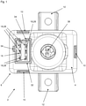
- the pyrotechnic circuit breaker 2 is designed for an on-board network of a motor vehicle and is accordingly used in a motor vehicle.
- the pyrotechnic circuit breaker 2 comprises a two-part plastic housing 8 consisting of an upper shell 4 and a lower shell 6, the upper shell 4 and the lower shell 6 being fastened to one another in the final assembly state by means of three snap-on connection elements 10 distributed on the other side.
- the upper shell 4 has two wings 12 which are positioned on two opposite sides of the upper shell 4 in the manner of lateral projections.
- the wings 12 have openings through which screws can be passed for attachment to the holding structure of the motor vehicle.
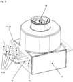
- a pyrotechnic unit 14 and a current-carrying plate 16 are arranged in the housing 8 of the pyrotechnic circuit breaker 2, with the current-carrying plate 16, as in FIG 3 outlined, the pyrotechnic unit 14 interspersed.
- the individually illustrated current-carrying plate 16 is in this case designed in one piece and in one piece as a stamped and bent plate and has an approximately rectangular basic geometry.
- Six connection elements 18 designed as flat, elongated tongues are positioned on one side of the current-carrying plate 16, which serve as plug-in contacts for a plug-in connection and essentially protrude perpendicularly from the rest of the current-carrying plate 16, that is to say protrude vertically from the plane of the current-carrying plate 16.
- the production of the current-carrying plate 16 takes place in two work steps, with a flat current-carrying plate 16 first being punched out of a sheet-metal strip.
- the tongue-like connection elements 18 are already formed and in a second subsequent processing step the connection elements 18 are then bent out of the plane of the current-carrying plate 16 and bent over until they protrude vertically.
- the current-carrying plate 16 has three retaining lugs 20, which are also designed like tongues and, like the connection elements 18, are bent out of the plane of the current-carrying plate 16 in the second processing step, but only a little.
- connection elements 18 are formed on the central sheet metal strip 22, this serving as an input connection 26 for a power supply via a supply line.
- connection elements 18 are formed on each of the two outer sheet metal strips 22 and are in the form of output connections 28 and are therefore provided for current discharge via a current discharge line.
- the two outer sheet metal strips 22 are also connected to one another via an outlet crosspiece 30 on which another connection element 18 embodied as an outlet connection 28 is formed.
- the pyrotechnic circuit breaker 2 thus has a current input with one plug contact and a current output with five plug contacts.
- the plug contacts, ie the connection elements 18, are arranged in two rows, each with three connection elements 18, and form a plug unit together with a housing wall 32 forming a housing socket.
- a complementary socket unit is plugged into a circuit, so that all six connection elements 18, i.e. both the input connection 26 and the five output connections 28, are connected to corresponding counter-elements of the circuit with just one movement.
- the housing wall 32 is as in 1 and 2 recognizable, designed as a frame-like projection on the top of the upper shell 4, in which the connection elements 18 are countersunk. Furthermore, the housing wall 32 is designed with regard to its geometry in such a way that there are guide elements 34 on two sides, which make it easier to bring the plug unit and socket unit together. In addition, a lateral opening 36 is formed in the housing wall 32, which serves as a functional counterpart to a latching lug on the socket unit, so that the socket unit can be latched on the plug unit.
- the pyrotechnic unit 14 which is not shown in all details, comprises a pyrotechnic propellant charge and an igniter, which is activated by an electrical signal, the trigger or ignition signal, and subsequently ignites the pyrotechnic propellant charge.
- the igniter has a signal input 38 to which a signal transmitter (not shown) can be connected for signals by means of a plug connection.
- the trigger condition for the pyrotechnic circuit breaker 2 is then specified by the signal generator, ie the condition in which the signal generator generates a trigger signal and transmits it to the igniter via the signal input 38, so that the latter ignites the pyrotechnic propellant charge.
- the pyrotechnic unit 14 includes a hammer element 40, called hammer 40 for short, and an anvil element 42, called anvil 42 for short. If the pyrotechnic propellant charge is ignited, it accelerates the hammer element 40 in the direction of the anvil element 42, as a result of which the sheet metal strips 22 positioned between the hammer element 40 and the anvil element 42 are severed in the central region of the current-carrying sheet metal 16.
- the hammer element 40 in the region of the front facing the anvil element 42 has a Web-like or strip-shaped mandrel 44, and on the anvil element 42 there is also a depression 46 adapted to the mandrel 44.
- the mandrel 44 in turn has a material cut-out in the central area, based on the longitudinal extent of the strip shape, or viewed conversely, additional material formations extending in the direction of the anvil element 42 are provided in the outer areas.
- the indentation 46 is also not designed as a simple groove with a uniform profile; instead, additional material recesses are provided at the edge relative to its longitudinal extent.
Description
Die Erfindung betrifft einen pyrotechnischen Schutzschalter, insbesondere für ein Kraftfahrzeug.The invention relates to a pyrotechnic circuit breaker, in particular for a motor vehicle.
Bei einem pyrotechnischen Schutzschalter, auch pyrotechnisches Sicherungselement genannt, handelt es sich nicht um eine Schutzvorrichtung zur Absicherung eines Strompfades gegen Überströme, wie dies beispielsweise bei Schmelzsicherungen der Fall ist. Stattdessen handelt es sich bei dem pyrotechnischen Schutzschalter, auch pyrotechnischer Sicherheitsschalter, pyrotechnisches Trennelement oder kurz pyrotechnischer Schalter genannt, um eine Art Notausschalter der Stopp-Kategorie 0 (EN ISO 13850:2008 Pkt. 4.1.4 und EN 60204-1:2006 Pkt. 9.2.2), welcher sich manuell auslösen lässt und/oder unter vorgegebenen Bedingungen automatisch angesteuert und ausgelöst wird.A pyrotechnic circuit breaker, also called a pyrotechnic fuse element, is not a protective device for protecting a current path against overcurrents, as is the case with fuses, for example. Instead, the pyrotechnic safety switch, also called pyrotechnic safety switch, pyrotechnic disconnecting element or pyrotechnic switch for short, is a type of emergency stop switch of category 0 (EN ISO 13850:2008 item 4.1.4 and EN 60204-1:2006 item 9.2.2), which can be triggered manually and/or is automatically controlled and triggered under specified conditions.
Hierbei ist der pyrotechnische Schutzschalter nach einem an sich bekannten Prinzip aufgebaut. Er umfasst einen pyrotechnischen Treibsatz, der typischerweise durch ein elektrisches Zündsignal, insbesondere ein Sensorsignal eines angeschlossenen Sensors, gezündet wird und infolgedessen einen Trennkörper, meist ein Keil oder ein Bolzen, beschleunigt, so dass dieser einen elektrischen Leiter, meist einen Leiterstreifen, mechanisch durchtrennt. Hierdurch wird die durch den elektrischen Leiter gegebene elektrische Verbindung, beispielsweise zwischen einer elektrischen Energiequelle, zum Beispiel einer Batterie in einem Kraftfahrzeug, und einem angeschlossenen Strompfad mit diversen Verbrauchern unterbrochen. Aufgrund dieses Funktionsprinzips wird ein solcher pyrotechnischer Schutzschalter mitunter auch als Batterietrennschalter bezeichnet.Here, the pyrotechnic circuit breaker is constructed according to a principle known per se. It comprises a pyrotechnic propellant charge, which is typically ignited by an electrical ignition signal, in particular a sensor signal from a connected sensor, and as a result accelerates a separating body, usually a wedge or a bolt, so that it mechanically severs an electrical conductor, usually a conductor strip. As a result, the electrical connection provided by the electrical conductor, for example between an electrical energy source, for example a battery in a motor vehicle, and a connected current path with various consumers is interrupted. Because of this functional principle, such a pyrotechnic circuit breaker is sometimes also referred to as a battery disconnect switch.
Verschiedene Ausführungen eines entsprechenden pyrotechnischen Schutzschalters sind beispielsweise in den Druckschriften
Ausgehend hiervon liegt der Erfindung die Aufgabe zugrunde, eine vorteilhafte Ausgestaltung für einen pyrotechnischen Schutzschalter anzugeben.Proceeding from this, the invention is based on the object of specifying an advantageous embodiment for a pyrotechnic circuit breaker.
Diese Aufgabe wird erfindungsgemäß gelöst durch einen pyrotechnischen Schutzschalter mit den Merkmalen des Anspruchs 1. Bevorzugte Weiterbildungen sind in den rückbezogenen Ansprüchen enthalten.This object is achieved according to the invention by a pyrotechnic circuit breaker having the features of claim 1. Preferred developments are contained in the dependent claims.
Ein entsprechender pyrotechnischer Schutzschalter ist dabei bevorzugt für ein Bordnetz eines Kraftfahrzeuges ausgelegt und umfasst ein Gehäuse, eine pyrotechnische Einheit sowie ein Stromführungsblech, auch Stromschiene genannt. Hierbei weist das Stromführungsblech zumindest zwei Anschlusselemente auf, von denen eines als Eingangsanschluss für eine Stromzuflussleitung und das andere als Ausgangsanschluss für eine Stromabführleitung ausgebildet ist, wobei zumindest eines dieser beiden Anschlusselemente als Steckkontakt einer Steckverbindung ausgestaltet ist.A corresponding pyrotechnic circuit breaker is preferably designed for an on-board network of a motor vehicle and includes a housing, a pyrotechnic unit and a current-carrying plate, also known as a busbar. The current-carrying plate has at least two connection elements, one of which is designed as an input connection for a current inflow line and the other as an output connection for a current discharge line, with at least one of these two connection elements being designed as a plug-in contact of a plug-in connection.
Während also pyrotechnische Schutzschalter nach dem Stand der Technik entweder nach Art einer Schelle an einem gegebenem Leiter befestigt oder nach Art einer Hülse über einen gegebenen Leiter gestülpt werden oder aber Anschlusselemente aufweisen, an welche elektrische Leiter durch Anlöten oder mit Hilfe einer Schraubverbindung elektrisch angebunden werden, weist der hier vorgestellte pyrotechnischeSo while pyrotechnic circuit breakers according to the prior art are either fastened to a given conductor in the manner of a clamp or slipped over a given conductor in the manner of a sleeve or have connection elements to which electrical conductors are electrically connected by soldering or with the aid of a screw connection, points out the pyrotechnic presented here
Schutzschalter Anschlusselemente auf, die als Steckkontakte der Stromschiene ausgebildet sind, sodass sich elektrische Leiter einfach und schnell mittels einer Steckverbindung elektrisch leitend an den pyrotechnischen Schutzschalter anbinden lassen.Circuit breaker connection elements, which are designed as plug contacts of the busbar, so that electrical conductors can be easily and quickly connected to the pyrotechnic circuit breaker in an electrically conductive manner by means of a plug connection.
Hierdurch lässt sich ein entsprechender pyrotechnischer Schutzschalter nicht nur einfach und schnell in einen Stromkreis und insbesondere in ein Bordnetz eines Kraftfahrzeugs einbinden, sondern ebenso schnell und einfach wieder entfernen, also im Bedarfsfall zum Beispiel austauschen. Der pyrotechnische Schutzschalter eignet sich damit insbesondere auch für den Einsatz in der Fließband- oder Massenproduktion von Produkten, auch Kraftfahrzeugen, für die die Verwendung pyrotechnischer Schutzschalter vorgesehen ist, da der einfache und schnelle Einbau des pyrotechnischen Schutzschalters den Produktionsprozess vereinfacht und beschleunigt.This allows a corresponding pyrotechnic circuit breaker not only easily and quickly in a circuit and in particular in a vehicle electrical system integrate the motor vehicle, but remove it again just as quickly and easily, i.e. replace it if necessary, for example. The pyrotechnic circuit breaker is therefore particularly suitable for use in the assembly line or mass production of products, including motor vehicles, for which the use of pyrotechnic circuit breakers is intended, since the simple and quick installation of the pyrotechnic circuit breaker simplifies and speeds up the production process.
Weiterhin sind alle Anschlusselemente des Stromführungsbleches und bevorzugt alle Anschlusselemente des pyrotechnischen Schutzschalters als Steckkontakte ausgebildet, sodass der Einbau eines entsprechenden pyrotechnischen Schutzschalters ausschließlich über Steckverbindungen erfolgt.Furthermore, all connection elements of the current-carrying plate and preferably all connection elements of the pyrotechnical circuit breaker are designed as plug-in contacts, so that a corresponding pyrotechnical circuit breaker is installed exclusively via plug-in connections.
Weiter ist die pyrotechnische Einheit des pyrotechnischen Schutzschalters bevorzugt einfach gehalten und nach an sich bekanntem Grundprinzip aufgebaut. Dabei umfasst die pyrotechnische Einheit zweckdienlicher Weise einen pyrotechnischen Treibsatz sowie einen elektrischen Zünder mit einem Signaleingang, so dass über den Signaleingang ein Auslösesignal oder Zündsignal in den Zünder eingespeist werden kann, welches den Zünder aktiviert und damit die Zündung des pyrotechnischen Treibsatzes auslöst. Der gezündete pyrotechnische Treibsatz wiederum beschleunigt ein nachfolgend als Hammerelement oder kurz Hammer bezeichnetes Bauteil, den sogenannten Trennkörper, der pyrotechnischen Einheit, welches hierdurch mit einer keilartig oder dornartig ausgestalteten Front voraus auf ein nachfolgend als Ambosselement oder kurz Amboss bezeichnetes Bauteil der pyrotechnischen Einheit zugetrieben wird. In der Folge wird dann zumindest ein Teil des Stromführungsbleches, welches zwischen Hammer und Amboss positioniert ist, durchtrennt oder aber das gesamte Stromführungsblech wird in einem Bereich, insbesondere einem Mittenbereich, als Ganzes durchtrennt. In jedem Fall aber bewirkt die Einspeisung eines Auslösesignals letzten Endes eine galvanische Trennung von Eingangsanschluss und Ausgangsanschluss, also die Unterbrechung der elektrischen Verbindung zwischen dem Eingangsanschluss und dem Ausgangsanschluss.Furthermore, the pyrotechnic unit of the pyrotechnic circuit breaker is preferably kept simple and constructed according to a basic principle known per se. The pyrotechnic unit expediently includes a pyrotechnic charge and an electrical igniter with a signal input, so that a trigger signal or ignition signal can be fed into the igniter via the signal input, which activates the igniter and thus triggers the ignition of the pyrotechnic charge. The ignited pyrotechnic propellant charge in turn accelerates a component, referred to below as the hammer element, or hammer for short, the so-called separating body, of the pyrotechnic unit, which is thereby driven with a wedge-like or spike-like front towards a component of the pyrotechnic unit, referred to below as the anvil element, or anvil for short. As a result, at least part of the current-carrying sheet metal, which is positioned between the hammer and anvil, is severed, or the entire current-carrying sheet metal is severed in one area, in particular a central area, as a whole. In any case, however, feeding in a triggering signal ultimately causes a galvanic isolation of the input connection and the output connection, ie the interruption of the electrical connection between the input connection and the output connection.
Im Rahmen des Einbaus des pyrotechnischen Schutzschalters, also im Rahmen der Einbindung in einen Stromkreis, wird der Signaleingang des Zünders signaltechnisch mit einem Signalgeber verbunden, durch welchen die Auslösebedingung für den pyrotechnischen Schutzschalter vorgegeben wird, der also beim Eintreten einer vorgegebenen Bedingung, dem Auslösefall, ein Auslösesignal generiert und an den pyrotechnischen Schalter übermittelt. Ist nun ein entsprechender pyrotechnischer Schutzschalter beispielsweise in einem Kraftfahrzeug verbaut, so dient zum Beispiel ein Airbag-Steuergerät im Kraftfahrzeug als Signalgeber, sodass im Falle eines Auslösens eines Airbags im Kraftfahrzeug auch der pyrotechnische Schutzschalter ausgelöst wird, also der pyrotechnische Treibsatz gezündet wird. Die Auslösung des pyrotechnischen Schutzschalters erfolgt dann, im Falle eines Verkehrsunfalls, wobei der pyrotechnische Schutzschalter hierbei typischer Weise derart in das Bordnetz des Kraftfahrzeuges eingebunden ist, dass durch die Auslösung elektrische Energiequellen des Kraftfahrzeuges nach einem Verkehrsunfall quasi isoliert und vom übrigen Kraftfahrzeug-Bordnetz getrennt werden. Dadurch wird verhindert, dass unfallbedingt freiliegende und/oder beschädigte elektrische Kabelverbindungen oder aber freiliegende und/oder beschädigte Elektronikkomponenten ein Risiko, insbesondere für Rettungskräfte, darstellen, also zum Beispiel auslaufendes Öl oder Benzin entzünden.As part of the installation of the pyrotechnic circuit breaker, i.e. as part of the integration into a circuit, the signal input of the detonator is connected in terms of signal technology to a signal generator, which specifies the trigger condition for the pyrotechnic circuit breaker, i.e. when a specified condition occurs, the trigger case, generates a trigger signal and transmits it to the pyrotechnic switch. If a corresponding pyrotechnic circuit breaker is installed in a motor vehicle, for example, an airbag control unit in the motor vehicle serves as a signal transmitter, so that if an airbag in the motor vehicle is triggered, the pyrotechnic circuit breaker is also triggered, i.e. the pyrotechnic propellant charge is ignited. The pyrotechnic circuit breaker is then triggered in the event of a traffic accident, with the pyrotechnic circuit breaker typically being integrated into the vehicle electrical system in such a way that, after a traffic accident, the electrical energy sources of the motor vehicle are virtually isolated and separated from the rest of the vehicle electrical system . This prevents electrical cable connections that are exposed and/or damaged as a result of an accident, or electronic components that are exposed and/or damaged, from posing a risk, in particular for rescue workers, for example from igniting leaking oil or petrol.
Auch das Stromführungsblech des pyrotechnischen Schutzschalters, welches beispielsweise aus Kupfer oder einer Kupferlegierung besteht, ist bevorzugt einfach gehalten, so dass das Stromführungsblech mit Hilfe weniger Arbeitsschritte gefertigt werden kann. Dabei ist das Stromführungsblech bevorzugt einstückig und einteilig ausgestaltet und bildet die Anschlusselemente durch konstruktive Gestaltungselemente, also zum Beispiel Vertiefungen oder Materialaussparungen, aus. Die Anschlusselemente sind somit Teil des einstückigen und einteiligen Stromverteilungsbleches und werden dementsprechend nicht mittels eines Fügeprozesses nachträglich angefügt. Günstig ist dabei zum Beispiel die Fertigung des Stromführungsbleches in einem Stanz- oder Stanzbiegeprozess, also die Ausgestaltung des Stromführungsbleches als Stanz- oder Stanzbiegeblech.The current-carrying plate of the pyrotechnic circuit breaker, which is made of copper or a copper alloy, for example, is preferably kept simple, so that the current-carrying plate can be manufactured using fewer work steps. In this case, the current-carrying plate is preferably designed in one piece and in one piece and forms the connecting elements by means of structural design elements, ie, for example, indentations or material recesses. The connection elements are therefore part of the one-piece and one-piece current distribution plate and are accordingly not subsequently attached by means of a joining process. In this case, for example, it is favorable to manufacture the current-carrying sheet metal in a stamping or stamping-bending process, ie the configuration of the current-carrying sheet metal as a stamped or stamped-bent sheet metal.
Weiterhin ist vorgesehen, dass alle Steckkontakte des Stromführungsbleches in einem Randbereich des Stromführungsbleches, insbesondere regelmäßig oder matrixartig, angeordnet sind, also relativ dicht beieinander positioniert sind. Alle Steckkontakte sind daher von einer Seite aus erreichbar. Zudem bietet diese kompakte Anordnung der Steckkontakte die Möglichkeit, am pyrotechnischen Schutzschalter eine (einzige) Stecker-Einheit auszubilden, sodass sich alle Stecckontakte des Stromführungsbleches nach dem Stecker-Buchse-Prinzip mit nur einem Handgriff elektrisch an einen Stromkreis anbinden lassen.Furthermore, it is provided that all plug contacts of the current-carrying plate are arranged in an edge region of the current-carrying plate, in particular regularly or in a matrix-like manner, that is to say are positioned relatively close together. All plug contacts are therefore accessible from one side. In addition, this compact arrangement of the plug contacts offers the possibility of forming a (single) plug unit on the pyrotechnic circuit breaker, so that all plug contacts of the current-carrying plate can be electrically connected to a circuit according to the plug-socket principle with just one movement.
Dabei ist es weiter vorteilhaft, alle Steckkontakte gleichartig und zum Beispiel stiftartig, also zylindrisch, oder als flache Zungen auszubilden. Günstig ist hierbei insbesondere eine zungenartige Ausgestaltung, zumindest, wenn das Stromführungsblech wie zuvor beschrieben als Stanzbiegeblech ausgestaltet ist. In diesem Fall ist dann bevorzugt für das Stanzbiegeblech eine einheitliche Stärke oder Dicke vorgesehen. Bevorzugt werden die im Rahmen des Stanzprozesses ausgebildeten Zungen im Rahmen einer Nachbearbeitung umgebogen, also aus der Ebene des Stromführungsbleches heraus gebogen. Die typischer Weise langgestreckten Zungen stehen nach dem Biegeprozess und somit nach Fertigstellung des Stromführungsbleches aus der Ebene des Stromführungsbleches heraus und bevorzugt etwa senkrecht vom übrigen Stromführungsblech ab.It is also advantageous to design all the plug contacts in the same way and, for example, as pins, that is to say cylindrical, or as flat tongues. A tongue-like configuration is particularly favorable here, at least if the current-carrying sheet metal is configured as a stamped and bent sheet metal, as described above. In this case, a uniform strength or thickness is then preferably provided for the stamped and bent sheet metal. The tongues formed as part of the stamping process are preferably bent over as part of post-processing, ie bent out of the plane of the current-carrying plate. After the bending process and thus after completion of the current-carrying plate, the typically elongated tongues protrude from the plane of the current-carrying plate and preferably approximately perpendicularly from the rest of the current-carrying plate.
Eine vergleichbare abgewinkelte Anordnung der Steckkontakte wird auch bei nicht- zungenartigen Steckkontakten bevorzugt, wobei die in der Regel länglichen Steckkontakte vorteilhafter Weise unabhängig davon hinsichtlich ihrer Längsausrichtung bevorzugt parallel zur Längsausrichtung der pyrotechnischen Einheit des pyrotechnischen Schutzschalters ausgerichtet sind, also typischer Weise parallel zur Wirkrichtung oder Bewegungsrichtung des Hammers der pyrotechnischen Einheit im Auslösefall, da hierdurch der pyrotechnische Schutzschalter besonders kompakt ausgeführt werden kann und dementsprechend dann auch ausgeführt wird.A comparable angled arrangement of the plug contacts is also preferred for non-tongue-like plug contacts, with the plug contacts, which are generally elongated, advantageously being aligned independently of this with regard to their longitudinal alignment, preferably parallel to the longitudinal alignment of the pyrotechnic unit of the pyrotechnic circuit breaker, i.e. typically parallel to the direction of action or direction of movement of the hammer of the pyrotechnic unit in the event of a trigger, since this allows the pyrotechnic circuit breaker to be made particularly compact and is then also made accordingly.
Gemäß einer weiteren vorteilhaften Ausgestaltung des pyrotechnischen Schutzschalters sind die Steckkontakte des Stromführungsbleches von zumindest einer Gehäusewandung des Gehäuses umgeben, sodass diese quasi versenkt angeordnet sind. Die entsprechende Gehäusewandung dient dann unter anderem zum Schutz der Steckkontakte, sodass diese zum Beispiel nicht versehentlich abgebrochen werden, noch bevor der pyrotechnische Schutzschalter zum Einsatz kommt.According to a further advantageous embodiment of the pyrotechnic circuit breaker, the plug contacts of the current-carrying plate are of at least one Housing wall of the housing surrounded, so they are arranged quasi sunk. The corresponding housing wall then serves, among other things, to protect the plug contacts so that they are not accidentally broken off, for example, even before the pyrotechnic circuit breaker is used.
In vorteilhafter Weiterbildung bildet die Gehäusewandung eine Gehäusebuchse aus, in welcher alle Steckkontakte des Stromführungsbleches angeordnet und somit quasi versenkt sind. Die Gehäusewandung ist dabei typischer Weise durch eine rahmenartige Anformung am Gehäuse gegeben. Ist dann, wie zuvor beschrieben, am pyrotechnischen Schutzschalter eine Stecker-Einheit ausgebildet, welche beim Einbau des pyrotechnischen Schutzschalters mit eine komplementären Buchsen-Einheit verbunden wird, so dient die die Gehäusebuchse ausbildende Gehäusewandung nicht nur zum Schutz der Steckkontakte vor mechanischer Belastung vor einem Einsatz des pyrotechnischen Schutzschalters, sondern darüber hinaus auch zur Ausbildung einer zusätzlichen mechanischen Steckverbindung zwischen der Gehäusewandung und einem entsprechenden Gegenstück an der Buchsen-Einheit, sodass die mechanische Belastung der Steckverbindung vorwiegend von Gehäusewandungen getragen wird und nicht den Steckkontakten zusetzt. Besonders hoch ist die mechanische Belastung dabei typischer Weise beim Ausbilden der Steckverbindung oder beim Lösen der Steckverbindung, wobei die Gehäusewandung hierbei als Führung dient, was die mechanische Belastung für die Steckkontakte limitiert.In an advantageous development, the housing wall forms a housing socket, in which all the plug-in contacts of the current-carrying plate are arranged and thus, as it were, countersunk. The housing wall is typically given by a frame-like molding on the housing. If, as described above, a plug unit is then formed on the pyrotechnic circuit breaker, which is connected to a complementary socket unit when the pyrotechnic circuit breaker is installed, the housing wall forming the housing socket serves not only to protect the plug contacts from mechanical stress before use of the pyrotechnic circuit breaker, but also to form an additional mechanical plug-in connection between the housing wall and a corresponding counterpart on the socket unit, so that the mechanical load on the plug-in connection is mainly borne by the housing walls and does not affect the plug contacts. The mechanical load is typically particularly high when forming the plug connection or when releasing the plug connection, with the housing wall serving as a guide here, which limits the mechanical load on the plug contacts.
Weiter ist das Stromführungsblech derart ausgestaltet, dass dieses zumindest zwei Blechstreifen oder Leiterstreifen aufweist, die im Wirkbereich der pyrotechnischen Einheit, also im Bereich zwischen Hammer und Amboss, im Wesentlichen parallel zueinander ausgerichtet sind. Dabei ist einer der beiden Blechstreifen als Teil eines Eingangsstrompfads elektrisch leitend an zumindest einen Eingangsanschluss angebunden, wohingegen der andere der zumindest zwei Blechstreifen als Teil eines Ausgangsstrompfades elektrisch leitend an zumindest einen Ausgangsanschluss angebunden ist. Hierdurch ergeben sich zusätzliche Freiheiten bei der Ausgestaltung des Stromführungsbleches und somit des pyrotechnischen Schutzschalters.Furthermore, the current-carrying metal sheet is designed in such a way that it has at least two metal strips or conductor strips which are aligned essentially parallel to one another in the effective area of the pyrotechnic unit, ie in the area between the hammer and the anvil. One of the two metal strips is electrically conductively connected to at least one input connection as part of an input current path, whereas the other of the at least two metal strips is electrically conductively connected to at least one output connection as part of an output current path. This results in additional freedoms in the design of the current-carrying plate and thus of the pyrotechnic circuit breaker.
Je nach Ausgestaltungsvariante und Anwendungszweck weist das Stromführungsblech darüber hinaus weitere Blechstreifen im Wirkbereich der pyrotechnischen Einheit auf, wobei jeder Blechstreifen entweder Teil eines Eingangsstrompfades oder Ausgangsstrompfades ist und dementsprechend an einen Eingangsanschluss bzw. an einen Ausgangsanschluss angebunden ist.Depending on the design variant and application, the current-carrying metal sheet also has additional metal strips in the effective range of the pyrotechnic unit, each metal strip being either part of an input current path or an output current path and correspondingly connected to an input connection or an output connection.
Im Auslösefall werden dann die Leiterstreifen durchtrennt, die an einen Eingangsanschluss angebunden und somit Teil eines Eingangsstrompfades sind. Alternativ werden alle Blechstreifen durchtrennt, die Teil eines Ausgangsstrompfades und somit an einen Ausgangsanschluss angebunden sind oder aber es werden alle diese Leiterstreifen durchtrennt, unabhängig davon, ob diese Teil eines Eingangsstrompfades oder eines Ausgangsstrompfades sind. An dieser Stelle sei darauf hingewiesen, dass sämtliche Leiterstreifen Teil des einstückigen Stromführungsbleches sind und somit durch Teile oder Abschnitte des Stromführungsbleches ausgebildet werden. Dementsprechend sind die Leiterstreifen oder Blechstreifen zumindest außerhalb des Wirkungsbereichs der pyrotechnischen Einheit miteinander verbunden, wobei die entsprechenden Übergangsbereiche oder Verbindungsbereiche ebenfalls eine streifenartige Form aufweisen können und in einigen Fällen aufweisen. Diese Übergangsbereiche werden jedoch im Auslösefall nicht zusätzlich durchtrennt.If triggered, the conductor strips that are connected to an input connection and are therefore part of an input current path are severed. Alternatively, all sheet metal strips are severed that are part of an output current path and are therefore connected to an output connection, or all these conductor strips are severed, regardless of whether they are part of an input current path or an output current path. At this point it should be pointed out that all conductor strips are part of the one-piece current-carrying plate and are therefore formed by parts or sections of the current-carrying plate. Correspondingly, the conductor strips or sheet metal strips are connected to one another at least outside the area of action of the pyrotechnic unit, whereby the corresponding transition areas or connection areas can also have, and in some cases have, a strip-like shape. However, these transition areas are not additionally severed in the event of a trigger.
Um eine Durchtrennung auch mit einem relativ kleinen oder schwachen pyrotechnischen Treibsatz bewerkstelligen zu können, was in der Regel gewünscht ist, weist das Stromführungsblech vorteilhafter Weise eine Solbruchstelle auf, die typischer Weise durch Materialaussparungen oder Durchbrüche ausgebildet wird. Für einige Anwendungszwecke ist die Solbruchstelle dabei derart gestaltet, dass diese durch zwei an gegenüberliegenden Seiten, nämlich der Oberseite und der Unterseite, des Stromführungsbleches positionierte Nuten ausgebildet wird. Da, wie zuvor beschrieben, im Wirkbereich der pyrotechnischen Einheit mehrere parallel zueinander ausgerichtete Blechstreifen oder Leiterstreifen positioniert sind, weisen alle Blechstreifen oder Leiterstreifen, die im Auslösefall durchtrennt werden sollen, entsprechende Nuten auf. Alternativ bildet eine Nut auf einer Seite, also zum Beispiel auf der Unterseite, des Stromführungsbleches die Solbruchstelle aus.In order to be able to accomplish a severing with a relatively small or weak pyrotechnic propellant charge, which is generally desirable, the current-carrying plate advantageously has a sol breaking point, which is typically formed by material recesses or openings. For some applications, the sol breaking point is designed in such a way that it is formed by two grooves positioned on opposite sides, namely the upper side and the lower side, of the current-carrying plate. Since, as described above, several sheet metal strips or conductor strips aligned parallel to one another are positioned in the effective range of the pyrotechnic unit all sheet metal strips or conductor strips that are to be severed in the event of a trip have corresponding grooves. Alternatively, a groove on one side, for example on the underside, of the current-carrying plate forms the sol breaking point.
Um eine entsprechende Durchtrennung zu erleichtern, ist es weiter vorgesehen, das Hammerelement der pyrotechnischen Einheit derart auszugestalten, dass dieses im Bereich der dem Ambosselement zugewandten Front einen abstehenden Dorn aufweist, und zudem das Ambosselement mit einer an den Dorn angepassten Vertiefung oder Materialaussparung zu versehen.In order to facilitate a corresponding severing, it is also provided to design the hammer element of the pyrotechnic unit in such a way that it has a protruding spike in the area of the front facing the anvil element, and also to provide the anvil element with a depression or material recess adapted to the spike.
Das Hammerelement, oder vielmehr der abstehende Dorn, ist derart gestaltet, dass zumindest zwei parallele Leiterstreifen im Wirkbereich der pyrotechnischen Einheit im Auslösefall zeitversetzt vom Hammerelement getroffen und in Folge dessen auch zeitversetzt durchtrennt werden.The hammer element, or rather the protruding mandrel, is designed in such a way that at least two parallel conductor strips in the effective range of the pyrotechnic unit are hit by the hammer element with a time delay when triggered and consequently also cut through with a time delay.
Der pyrotechnische Schutzschalter ist bevorzugt als vorgefertigte Montagebaueinheit mit integriertem Stromführungsblech und integrierter pyrotechnischer Einheit ausgebildet und insbesondere derart gestaltet, dass die Montagebaueinheit ausschließlich mit Hilfe von Steckkontakten in einen Stromkreis und insbesondere in ein Bordnetz eines Kraftfahrzeuges elektrisch eingebunden wird. Vorzugsweise sind nicht nur die Anschlusselemente des Stromführungsbleches als Steckkontakte ausgeführt, sondern auch der Signaleingang an der pyrotechnischen Einheit, über welchen ein Auslösesignal zur Auslösung der pyrotechnischen Einheit und somit zur Zündung des pyrotechnischen Treibsatzes eingespeist werden kann.The pyrotechnic circuit breaker is preferably designed as a prefabricated assembly unit with an integrated current-carrying plate and an integrated pyrotechnic unit and is designed in particular in such a way that the assembly unit is electrically integrated exclusively with the aid of plug-in contacts in a circuit and in particular in an on-board network of a motor vehicle. Preferably, not only the connection elements of the current-carrying plate are designed as plug-in contacts, but also the signal input on the pyrotechnic unit, via which a trigger signal for triggering the pyrotechnic unit and thus for igniting the pyrotechnic charge can be fed.
Ausführungsbeispiele der Erfindung werden nachfolgend anhand einer schematischen Zeichnung näher erläutert. Darin zeigen:
- FIG 1
- in einer Ansicht einen pyrotechnischen Schutzschalter mit einem Gehäuse,
- FIG 2
- in einer perspektivischen Seitenansicht den pyrotechnischen Schutzschalter,
- FIG 3
- in einer perspektivischen Seitenansicht eine in dem Gehäuse angeordnete pyrotechnische Einheit zusammen mit einem Stromführungsblech,
- FIG 4
- in einer perspektivischen Seitenansicht das Stromführungsblech,
- FIG 5
- in einer perspektivischen Seitenansicht ein Hammerelement und ein Ambosselement der pyrotechnischen Einheit,
- FIG 1
- in a view a pyrotechnic circuit breaker with a housing,
- FIG 2
- in a perspective side view the pyrotechnic circuit breaker,
- 3
- in a perspective side view, a pyrotechnic unit arranged in the housing together with a current-carrying plate,
- FIG 4
- in a perspective side view the current conducting plate,
- 5
- in a perspective side view a hammer element and an anvil element of the pyrotechnic unit,
Einander entsprechende Teile sind in allen Figuren jeweils mit den gleichen Bezugszeichen versehen.Corresponding parts are provided with the same reference symbols in all figures.
Ein nachfolgend exemplarisch beschriebener und in
Im Gehäuse 8 des pyrotechnischen Schutzschalters 2 sind eine pyrotechnische Einheit 14 sowie ein Stromführungsblech 16 angeordnet, wobei das Stromführungsblech 16, wie in
Die Herstellung des Stromführungsbleches 16 erfolgt dementsprechend in zwei Arbeitsschritten, wobei zunächst ein ebenes Stromführungsblech 16 aus einem Blechband ausgestanzt wird. Bei diesem sind die zungenartigen Anschlusselemente 18 bereits ausgebildet und in einem zweiten sich anschließenden Bearbeitungsschritt werden dann die Anschlusselemente 18 aus der Ebene des Stromführungsbleches 16 heraus gebogen und soweit umgebogen, bis diese senkrecht abstehen. Darüber hinaus weist das Stromführungsblech 16 noch drei Haltenasen 20 auf, die ebenfalls zungenartig ausgestaltet sind und wie die Anschlusselemente 18 im zweiten Bearbeitungsschritt aus der Ebene des Stromführungsbleches 16 heraus gebogen werden, allerdings lediglich ein Stück weit.Accordingly, the production of the current-carrying
Im Mittenbereich des Stromführungsbleches 16 sind drei im Wesentlichen parallel zueinander angeordnete Blechstreifen 22 ausgebildet, die an dem den Anschlusselementen 18 abgewandten Ende des Stromführungsbleches 16 über ein Querverbindungselement 24 miteinander verbunden sind. An den mittleren Blechstreifen 22 ist eines der Anschlusselemente 18 angeformt, wobei dieses als Eingangsanschluss 26 für eine Stromeinspeisung über eine Zuführleitung dient. An die zwei äußeren Blechstreifen 22 sind jeweils zwei Anschlusselemente 18 angeformt, die als Ausgangsanschlüsse 28 ausgebildet und somit für eine Stromabführung über eine Stromabführleitung vorgesehen sind. Die beiden äußeren Blechstreifen 22 sind zudem über einen Ausgangsquersteg 30 miteinander verbunden, an welchem ein weiteres als Ausgangsanschluss 28 ausgebildetes Anschlusselement 18 angeformt ist.In the central region of the current-carrying
Der pyrotechnische Schutzschalter 2 weist somit in diesem Ausführungsbeispiel einen Stromeingang mit einem Steckkontakt und einen Stromausgang mit fünf Steckkontakten auf. Die Steckkontakte, also die Anschlusselemente 18, sind dabei in zwei Reihen mit je drei Anschlusselementen 18 angeordnet und bilden zusammen mit einer eine Gehäusebuchse ausbildenden Gehäusewandung 32 eine Stecker-Einheit aus. In diese wird beim Einbinden des pyrotechnischen Schutzschalters 2 in einen Stromkreis eine komplementär ausgebildete Buchsen-Einheit eingesteckt, sodass mit nur einem Handgriff alle sechs Anschlusselemente 18, also sowohl der Eingangsanschluss 26 als auch die fünf Ausgangsanschlüsse 28, mit entsprechenden Gegenelementen des Stromkreises verbunden werden.In this exemplary embodiment, the
Die Gehäusewandung 32 ist dabei, wie in
Die nicht in allen Details dargestellte pyrotechnische Einheit 14 umfasst einen pyrotechnischen Treibsatz und einen Zünder, der durch ein elektrisches Signal, das Auslöse- oder Zündsignal, aktiviert wird und nachfolgend den pyrotechnischen Treibsatz zündet. Dabei weist der Zünder einen Signaleingang 38 auf, an welchen sich ein nicht mit abgebildeter Signalgeber mittels einer Steckverbindung signaltechnisch anschließen lässt. Durch den Signalgeber ist dann die Auslösebedingung für den pyrotechnischen Schutzschalter 2 vorgegeben, also diejenige Bedingung, bei der der Signalgeber ein Auslösesignal generiert und an den Zünder über den Signaleingang 38 übermittelt, sodass dieser den pyrotechnischen Treibsatz zündet.The
Desweiteren umfasst die pyrotechnische Einheit 14 ein Hammerelement 40, kurz Hammer 40 genannt, sowie ein Ambosselement 42, kurz Amboss 42 genannt. Wird nun der pyrotechnische Treibsatz gezündet, so beschleunigt dieser das Hammerelement 40 in Richtung Ambosselement 42, wodurch die zwischen Hammerelement 40 und Ambosselement 42 positionierten Blechstreifen 22 im Mittenbereich des Stromführungsbleches 16 durchtrennt werden. Dabei weist das Hammerelement 40 im Bereich der dem Ambosselement 42 zugewandten Front einen stegartigen oder leistenförmigen Dorn 44 auf, und am Ambosselement 42 ist ergänzend dazu eine an den Dorn 44 angepasst Vertiefung 46 gegeben.Furthermore, the
Der Dorn 44 wiederum weist im Mittenbereich, bezogen auf die Längsausdehnung der Leistenform, eine Materialaussparung auf oder umgekehrt betrachtet sind in den Außenbereichen zusätzliche sich in Richtung Ambosselement 42 erstreckende Materialanformungen gegeben. Komplementär hierzu ist auch die Vertiefung 46 nicht als einfache Nut mit einheitlichem Profil ausgebildet, stattdessen sind bezogen auf deren Längsausdehnung randseitig zusätzliche Materialaussparungen vorgesehen. Infolgedessen trifft der Dorn 44 im Auslösefall zunächst auf die äußeren Blechstreifen 22 und etwas zeitversetzt dazu auf den mittleren Blechstreifen 22, sodass der mittlere Streifen 22 zeitversetzt zu den äußeren Blechstreifen 22 durchtrennt wird.The
Um die Durchtrennung zu erleichtern oder vielmehr um einen kleineren oder schwächeren pyrotechnischen Treibsatz verwenden zu können, ist am Stromführungsblech 16 eine Sollbruchstelle 48 gegeben, die durch eine Nut an der Unterseite eines jeweiligen Blechstreifens 22 ausgebildet ist.In order to facilitate the severing, or rather to be able to use a smaller or weaker pyrotechnic propellant charge, there is a
Die Erfindung ist nicht auf das vorstehend beschriebene Ausführungsbeispiel beschränkt. Vielmehr können auch andere Varianten der Erfindung von dem Fachmann hieraus abgeleitet werden, ohne den Gegenstand der Erfindung zu verlassen.The invention is not limited to the embodiment described above. On the contrary, other variants of the invention can also be derived from this by a person skilled in the art without departing from the subject matter of the invention.
- 22
- Pyrotechnischer SchutzschalterPyrotechnic circuit breaker
- 44
- OberschaleUpper shell
- 66
- Unterschalebottom shell
- 88th
- Gehäusehousing
- 1010
- Schnappverbindungselementsnap fastener
- 1212
- Flügelwing
- 1414
- Pyrotechnische Einheitpyrotechnic unit
- 1616
- Stromführungsblechcurrent conducting plate
- 1818
- Anschlusselementconnection element
- 2020
- Haltenaseholding lug
- 2222
- Blechstreifensheet metal strips
- 2424
- Querverbindungselementcross connector
- 2626
- Eingangsanschlussinput port
- 2828
- Ausgangsanschlussoutput port
- 3030
- Ausgangsquerstegexit traverse
- 3232
- Gehäusewandunghousing wall
- 3434
- Führungselementguide element
- 3636
- Durchbruchbreakthrough
- 3838
- Signaleingangsignal input
- 4040
- Hammerelementhammer element
- 4242
- Ambosselementanvil element
- 4444
- Dornmandrel
- 4646
- Vertiefungdeepening
- 4848
- Sollbruchstellepredetermined breaking point
- 5050
- Längsrichtunglongitudinal direction
Claims (11)
- A pyrotechnic circuit breaker (2), in particular for a motor vehicle, comprising a housing (8), a current carrying sheet metal (16) with at least two terminal elements (18) as well as a pyrotechnic unit (14) for cutting through at least a part of the current carrying sheet metal (16), wherein one of the at least two terminal elements (18) of the current carrying sheet metal (16) is formed as an input terminal (26) for a current supply line and the other of the at least two terminal elements (18) is formed as an output terminal (28) for a current discharge line,
characterised,
in that all terminal elements (18) of the current carrying sheet metal (16) are formed as plug contacts of a plug connection and all terminal elements (18) of the input terminal (26) as well as of the output terminal (28) are arranged on one side in a border area of the current carrying sheet metal (16) and form a plug unit and in that the current carrying sheet metal (16) has at least two sheet metal strips (22), which are aligned substantially parallel to one another in the operating area of the pyrotechnic unit (14), wherein one of the at least two sheet metal strips (22) is connected to the input terminal (26) in an electrically conductive manner as part of an input current path and wherein the other of the at least two sheet metal strips (22) is connected to the output terminal (28) in an electrically conductive manner as part of an output current path, wherein the sheet metal strips (22) are connected together outside of the operating area of the pyrotechnic unit,
wherein the pyrotechnic unit (14) comprises a hammer element (40), which is driven towards an anvil element (42) in the case of triggering, and wherein the hammer element (40) is designed such that, in the case of triggering, the two sheet metal strips (22) are struck and cut through by the hammer element (40) in a time-delayed manner. - The pyrotechnic circuit breaker (2) according to claim 1,
characterised,
in that the current carrying sheet metal (16) is formed as a single piece stamping and bending sheet metal with the terminal elements (18). - The pyrotechnic circuit breaker (2) according to claim 1 or 2,
characterised,
in that the input terminal (26) and the output terminal (28) are connected together via a cross-connection element (24) of the current carrying sheet metal (16), which is arranged opposite the input terminal (26) and the output terminal (28) in a second border area of the current carrying sheet metal (16). - The pyrotechnic circuit breaker (2) according to any one of claims 1 to 3,
characterised,
in that the terminal elements (18) of the current carrying sheet metal (16) are arranged like a matrix. - The pyrotechnic circuit breaker (2) according to any of claims 1 to 4,
characterised,
in that the terminal elements (18) of the current carrying sheet metal (16) are designed as bent tongues of the current carrying sheet metal (16). - The pyrotechnic circuit breaker (2) according to any of claims 1 to 5,
characterised,
in that the current carrying sheet metal (16) has projecting terminal elements (18). - The pyrotechnic circuit breaker (2) according to any of claims 1 to 6,
characterised,
in that the current carrying sheet metal (16) has substantially vertically projecting terminal elements (18). - The pyrotechnic circuit breaker (2) according to any of claims 1 to 7,
characterised,
in that all terminal elements (18) of the current carrying sheet metal (16) are surrounded by a housing wall (32) of the housing (8). - The pyrotechnic circuit breaker (2) according to claim 8,
characterised,
in that the housing wall (32) forms a housing bushing, in which all terminal elements (18) of the current carrying sheet metal (16) are arranged. - The pyrotechnic circuit breaker (2) according to any of claims 1 to 9,
characterised,
in that a predetermined breaking point (48) is formed on the current carrying sheet metal (16). - The pyrotechnic circuit breaker (2) according to any of claims 1 to 10,
characterised,
in that this is formed as prefabricated assembly unit with integrated current carrying sheet metal (16) and integrated pyrotechnic unit (14) such that the assembly unit is electrically incorporated into a circuit and in particular into an on-board network of a motor vehicle exclusively with the help of the plug contacts.
Applications Claiming Priority (2)
| Application Number | Priority Date | Filing Date | Title |
|---|---|---|---|
| DE102014222230.3A DE102014222230A1 (en) | 2014-10-30 | 2014-10-30 | Pyrotechnic circuit breaker |
| PCT/EP2015/075025 WO2016066707A1 (en) | 2014-10-30 | 2015-10-28 | Pyrotechnical circuit breaker |
Publications (2)
| Publication Number | Publication Date |
|---|---|
| EP3213336A1 EP3213336A1 (en) | 2017-09-06 |
| EP3213336B1 true EP3213336B1 (en) | 2022-03-02 |
Family
ID=54703928
Family Applications (1)
| Application Number | Title | Priority Date | Filing Date |
|---|---|---|---|
| EP15800726.0A Active EP3213336B1 (en) | 2014-10-30 | 2015-10-28 | Pyrotechnical circuit breaker |
Country Status (3)
| Country | Link |
|---|---|
| EP (1) | EP3213336B1 (en) |
| DE (1) | DE102014222230A1 (en) |
| WO (1) | WO2016066707A1 (en) |
Families Citing this family (1)
| Publication number | Priority date | Publication date | Assignee | Title |
|---|---|---|---|---|
| DE102017207735B3 (en) | 2017-05-08 | 2018-08-23 | Leoni Bordnetz-Systeme Gmbh | Pyrotechnic disconnector |
Citations (1)
| Publication number | Priority date | Publication date | Assignee | Title |
|---|---|---|---|---|
| US3909767A (en) * | 1974-01-14 | 1975-09-30 | Littelfuse Inc | Miniature plug-in fuse |
Family Cites Families (10)
| Publication number | Priority date | Publication date | Assignee | Title |
|---|---|---|---|---|
| DE3931188A1 (en) * | 1989-09-19 | 1991-03-28 | Baer Elektrowerke Gmbh & Co Kg | Independent switches combination in compartment housing - forming plug by allowing contact from each switch to project from side |
| DE19616994A1 (en) * | 1996-04-27 | 1997-10-30 | Dynamit Nobel Ag | Pyrotechnic fuse element for circuits |
| DE19749896A1 (en) * | 1997-11-12 | 1999-06-02 | Knipping Kunststofftechnik Wer | Pyrotechnical safety switch for motor vehicle |
| DE29917468U1 (en) * | 1999-10-04 | 1999-12-16 | Draexlmaier Lisa Gmbh | Relay module |
| DE102004008120A1 (en) * | 2003-02-26 | 2004-11-25 | Dynamit Nobel Ais Gmbh Automotive Ignition Systems | Pyromechanical separating device with specially shaped current conducting rail has cable connectors at both end pieces at right angles to plane of separating point formed by conductor narrow point |
| US7498531B2 (en) * | 2003-03-12 | 2009-03-03 | Delphi Technologies, Inc. | Housing and a conducting rail for disconnecting a battery |
| JP4412147B2 (en) * | 2004-10-21 | 2010-02-10 | アンデン株式会社 | Electrical component equipment |
| US7841911B2 (en) * | 2005-11-25 | 2010-11-30 | Autonetworks Technologies, Ltd. | Joint part and a wiring harness using the same |
| DE102009025425B4 (en) * | 2009-06-16 | 2012-02-02 | Autokabel-Managementgesellschaft Mbh | Electric separator and vehicle with it |
| JP5817685B2 (en) * | 2012-08-31 | 2015-11-18 | 豊田合成株式会社 | Conduction interruption device |
-
2014
- 2014-10-30 DE DE102014222230.3A patent/DE102014222230A1/en not_active Ceased
-
2015
- 2015-10-28 EP EP15800726.0A patent/EP3213336B1/en active Active
- 2015-10-28 WO PCT/EP2015/075025 patent/WO2016066707A1/en active Application Filing
Patent Citations (1)
| Publication number | Priority date | Publication date | Assignee | Title |
|---|---|---|---|---|
| US3909767A (en) * | 1974-01-14 | 1975-09-30 | Littelfuse Inc | Miniature plug-in fuse |
Also Published As
| Publication number | Publication date |
|---|---|
| DE102014222230A1 (en) | 2016-05-04 |
| EP3213336A1 (en) | 2017-09-06 |
| WO2016066707A1 (en) | 2016-05-06 |
Similar Documents
| Publication | Publication Date | Title |
|---|---|---|
| DE102016116781B4 (en) | Open circuit device | |
| DE102012221664B4 (en) | short-circuit switch | |
| DE102010011150A1 (en) | Fuse for motor vehicle power line | |
| DE102011014343A1 (en) | Safety device for a power supply of a motor vehicle | |
| EP1469564A1 (en) | Pyrotechnical battery terminal | |
| EP3622548B1 (en) | Pyrotechnic circuit breaker and supply system having a pyrotechnic circuit breaker | |
| DE102016109428A1 (en) | Line separator device | |
| DE112018005130T5 (en) | ELECTRICAL PROTECTIVE SWITCHING DEVICE | |
| DE102007051504A1 (en) | Safety device for use in e.g. electric or hybrid vehicle, has outer contour of separation body adjusted to inner contour of passage such that ignition chamber is connected with surge chamber after separation of conductor | |
| EP2020013A1 (en) | Method and devicefor single and permanent disconnection of an electrical connection, in particular in a vehicle | |
| EP3525223B1 (en) | Pyrotechnic switch | |
| EP3251141B1 (en) | Pyrotechnic safety element | |
| DE102016216829A1 (en) | Separating device for separating an electrical connection between two components of a motor vehicle, and device with such a separating device | |
| EP3213336B1 (en) | Pyrotechnical circuit breaker | |
| DE102015225521B4 (en) | Device for switching an electrical circuit, vehicle with such a device and a method for its operation | |
| DE10209626B4 (en) | Pyrotechnic switch | |
| EP3192093B1 (en) | Multi-fuse arrangement | |
| DE102008013831B4 (en) | Separating device for separating at least two electrical circuits and motor vehicle with this | |
| EP3622549B1 (en) | Pyrotechnic circuit breaker and supply grid with a pyrotechnic circuit breaker | |
| DE102017217520A1 (en) | Safety arrangement for an electrical component of a motor vehicle and motor vehicle with such a safety arrangement | |
| EP3618089B1 (en) | Pyrotechnic current disconnector | |
| DE102017207735B3 (en) | Pyrotechnic disconnector | |
| DE102020112918B4 (en) | Electrical isolating device, system with a isolating device and method for producing a isolating device | |
| DE10337980A1 (en) | Pyromechanical battery pole separator | |
| DE102014108245A1 (en) | Safety device for interrupting a high-voltage line for a motor vehicle |
Legal Events
| Date | Code | Title | Description |
|---|---|---|---|
| STAA | Information on the status of an ep patent application or granted ep patent |
Free format text: STATUS: THE INTERNATIONAL PUBLICATION HAS BEEN MADE |
|
| PUAI | Public reference made under article 153(3) epc to a published international application that has entered the european phase |
Free format text: ORIGINAL CODE: 0009012 |
|
| STAA | Information on the status of an ep patent application or granted ep patent |
Free format text: STATUS: REQUEST FOR EXAMINATION WAS MADE |
|
| 17P | Request for examination filed |
Effective date: 20170407 |
|
| AK | Designated contracting states |
Kind code of ref document: A1 Designated state(s): AL AT BE BG CH CY CZ DE DK EE ES FI FR GB GR HR HU IE IS IT LI LT LU LV MC MK MT NL NO PL PT RO RS SE SI SK SM TR |
|
| AX | Request for extension of the european patent |
Extension state: BA ME |
|
| DAV | Request for validation of the european patent (deleted) | ||
| DAX | Request for extension of the european patent (deleted) | ||
| STAA | Information on the status of an ep patent application or granted ep patent |
Free format text: STATUS: EXAMINATION IS IN PROGRESS |
|
| 17Q | First examination report despatched |
Effective date: 20191113 |
|
| STAA | Information on the status of an ep patent application or granted ep patent |
Free format text: STATUS: EXAMINATION IS IN PROGRESS |
|
| STAA | Information on the status of an ep patent application or granted ep patent |
Free format text: STATUS: EXAMINATION IS IN PROGRESS |
|
| GRAP | Despatch of communication of intention to grant a patent |
Free format text: ORIGINAL CODE: EPIDOSNIGR1 |
|
| STAA | Information on the status of an ep patent application or granted ep patent |
Free format text: STATUS: GRANT OF PATENT IS INTENDED |
|
| INTG | Intention to grant announced |
Effective date: 20211214 |
|
| GRAS | Grant fee paid |
Free format text: ORIGINAL CODE: EPIDOSNIGR3 |
|
| GRAA | (expected) grant |
Free format text: ORIGINAL CODE: 0009210 |
|
| STAA | Information on the status of an ep patent application or granted ep patent |
Free format text: STATUS: THE PATENT HAS BEEN GRANTED |
|
| AK | Designated contracting states |
Kind code of ref document: B1 Designated state(s): AL AT BE BG CH CY CZ DE DK EE ES FI FR GB GR HR HU IE IS IT LI LT LU LV MC MK MT NL NO PL PT RO RS SE SI SK SM TR |
|
| REG | Reference to a national code |
Ref country code: GB Ref legal event code: FG4D Free format text: NOT ENGLISH |
|
| RIN1 | Information on inventor provided before grant (corrected) |
Inventor name: WOLF, SASCHA Inventor name: WAGNER, GUNNAR Inventor name: STEINER, PETER Inventor name: HOPF, MARTIN |
|
| REG | Reference to a national code |
Ref country code: CH Ref legal event code: EP Ref country code: AT Ref legal event code: REF Ref document number: 1472928 Country of ref document: AT Kind code of ref document: T Effective date: 20220315 |
|
| REG | Reference to a national code |
Ref country code: DE Ref legal event code: R096 Ref document number: 502015015684 Country of ref document: DE |
|
| REG | Reference to a national code |
Ref country code: IE Ref legal event code: FG4D Free format text: LANGUAGE OF EP DOCUMENT: GERMAN |
|
| REG | Reference to a national code |
Ref country code: LT Ref legal event code: MG9D |
|
| REG | Reference to a national code |
Ref country code: NL Ref legal event code: MP Effective date: 20220302 |
|
| PG25 | Lapsed in a contracting state [announced via postgrant information from national office to epo] |
Ref country code: SE Free format text: LAPSE BECAUSE OF FAILURE TO SUBMIT A TRANSLATION OF THE DESCRIPTION OR TO PAY THE FEE WITHIN THE PRESCRIBED TIME-LIMIT Effective date: 20220302 Ref country code: RS Free format text: LAPSE BECAUSE OF FAILURE TO SUBMIT A TRANSLATION OF THE DESCRIPTION OR TO PAY THE FEE WITHIN THE PRESCRIBED TIME-LIMIT Effective date: 20220302 Ref country code: NO Free format text: LAPSE BECAUSE OF FAILURE TO SUBMIT A TRANSLATION OF THE DESCRIPTION OR TO PAY THE FEE WITHIN THE PRESCRIBED TIME-LIMIT Effective date: 20220602 Ref country code: LT Free format text: LAPSE BECAUSE OF FAILURE TO SUBMIT A TRANSLATION OF THE DESCRIPTION OR TO PAY THE FEE WITHIN THE PRESCRIBED TIME-LIMIT Effective date: 20220302 Ref country code: HR Free format text: LAPSE BECAUSE OF FAILURE TO SUBMIT A TRANSLATION OF THE DESCRIPTION OR TO PAY THE FEE WITHIN THE PRESCRIBED TIME-LIMIT Effective date: 20220302 Ref country code: ES Free format text: LAPSE BECAUSE OF FAILURE TO SUBMIT A TRANSLATION OF THE DESCRIPTION OR TO PAY THE FEE WITHIN THE PRESCRIBED TIME-LIMIT Effective date: 20220302 Ref country code: BG Free format text: LAPSE BECAUSE OF FAILURE TO SUBMIT A TRANSLATION OF THE DESCRIPTION OR TO PAY THE FEE WITHIN THE PRESCRIBED TIME-LIMIT Effective date: 20220602 |
|
| PG25 | Lapsed in a contracting state [announced via postgrant information from national office to epo] |
Ref country code: PL Free format text: LAPSE BECAUSE OF FAILURE TO SUBMIT A TRANSLATION OF THE DESCRIPTION OR TO PAY THE FEE WITHIN THE PRESCRIBED TIME-LIMIT Effective date: 20220302 Ref country code: LV Free format text: LAPSE BECAUSE OF FAILURE TO SUBMIT A TRANSLATION OF THE DESCRIPTION OR TO PAY THE FEE WITHIN THE PRESCRIBED TIME-LIMIT Effective date: 20220302 Ref country code: GR Free format text: LAPSE BECAUSE OF FAILURE TO SUBMIT A TRANSLATION OF THE DESCRIPTION OR TO PAY THE FEE WITHIN THE PRESCRIBED TIME-LIMIT Effective date: 20220603 Ref country code: FI Free format text: LAPSE BECAUSE OF FAILURE TO SUBMIT A TRANSLATION OF THE DESCRIPTION OR TO PAY THE FEE WITHIN THE PRESCRIBED TIME-LIMIT Effective date: 20220302 |
|
| PG25 | Lapsed in a contracting state [announced via postgrant information from national office to epo] |
Ref country code: NL Free format text: LAPSE BECAUSE OF FAILURE TO SUBMIT A TRANSLATION OF THE DESCRIPTION OR TO PAY THE FEE WITHIN THE PRESCRIBED TIME-LIMIT Effective date: 20220302 |
|
| PG25 | Lapsed in a contracting state [announced via postgrant information from national office to epo] |
Ref country code: SM Free format text: LAPSE BECAUSE OF FAILURE TO SUBMIT A TRANSLATION OF THE DESCRIPTION OR TO PAY THE FEE WITHIN THE PRESCRIBED TIME-LIMIT Effective date: 20220302 Ref country code: SK Free format text: LAPSE BECAUSE OF FAILURE TO SUBMIT A TRANSLATION OF THE DESCRIPTION OR TO PAY THE FEE WITHIN THE PRESCRIBED TIME-LIMIT Effective date: 20220302 Ref country code: RO Free format text: LAPSE BECAUSE OF FAILURE TO SUBMIT A TRANSLATION OF THE DESCRIPTION OR TO PAY THE FEE WITHIN THE PRESCRIBED TIME-LIMIT Effective date: 20220302 Ref country code: PT Free format text: LAPSE BECAUSE OF FAILURE TO SUBMIT A TRANSLATION OF THE DESCRIPTION OR TO PAY THE FEE WITHIN THE PRESCRIBED TIME-LIMIT Effective date: 20220704 Ref country code: EE Free format text: LAPSE BECAUSE OF FAILURE TO SUBMIT A TRANSLATION OF THE DESCRIPTION OR TO PAY THE FEE WITHIN THE PRESCRIBED TIME-LIMIT Effective date: 20220302 Ref country code: CZ Free format text: LAPSE BECAUSE OF FAILURE TO SUBMIT A TRANSLATION OF THE DESCRIPTION OR TO PAY THE FEE WITHIN THE PRESCRIBED TIME-LIMIT Effective date: 20220302 |
|
| PG25 | Lapsed in a contracting state [announced via postgrant information from national office to epo] |
Ref country code: IS Free format text: LAPSE BECAUSE OF FAILURE TO SUBMIT A TRANSLATION OF THE DESCRIPTION OR TO PAY THE FEE WITHIN THE PRESCRIBED TIME-LIMIT Effective date: 20220702 Ref country code: AL Free format text: LAPSE BECAUSE OF FAILURE TO SUBMIT A TRANSLATION OF THE DESCRIPTION OR TO PAY THE FEE WITHIN THE PRESCRIBED TIME-LIMIT Effective date: 20220302 |
|
| REG | Reference to a national code |
Ref country code: DE Ref legal event code: R097 Ref document number: 502015015684 Country of ref document: DE |
|
| PGFP | Annual fee paid to national office [announced via postgrant information from national office to epo] |
Ref country code: FR Payment date: 20221020 Year of fee payment: 8 |
|
| PLBE | No opposition filed within time limit |
Free format text: ORIGINAL CODE: 0009261 |
|
| STAA | Information on the status of an ep patent application or granted ep patent |
Free format text: STATUS: NO OPPOSITION FILED WITHIN TIME LIMIT |
|
| PG25 | Lapsed in a contracting state [announced via postgrant information from national office to epo] |
Ref country code: DK Free format text: LAPSE BECAUSE OF FAILURE TO SUBMIT A TRANSLATION OF THE DESCRIPTION OR TO PAY THE FEE WITHIN THE PRESCRIBED TIME-LIMIT Effective date: 20220302 |
|
| PGFP | Annual fee paid to national office [announced via postgrant information from national office to epo] |
Ref country code: GB Payment date: 20221024 Year of fee payment: 8 Ref country code: DE Payment date: 20221020 Year of fee payment: 8 |
|
| 26N | No opposition filed |
Effective date: 20221205 |
|
| PG25 | Lapsed in a contracting state [announced via postgrant information from national office to epo] |
Ref country code: SI Free format text: LAPSE BECAUSE OF FAILURE TO SUBMIT A TRANSLATION OF THE DESCRIPTION OR TO PAY THE FEE WITHIN THE PRESCRIBED TIME-LIMIT Effective date: 20220302 |
|
| PG25 | Lapsed in a contracting state [announced via postgrant information from national office to epo] |
Ref country code: MC Free format text: LAPSE BECAUSE OF FAILURE TO SUBMIT A TRANSLATION OF THE DESCRIPTION OR TO PAY THE FEE WITHIN THE PRESCRIBED TIME-LIMIT Effective date: 20220302 |
|
| REG | Reference to a national code |
Ref country code: CH Ref legal event code: PL |
|
| REG | Reference to a national code |
Ref country code: BE Ref legal event code: MM Effective date: 20221031 |
|
| PG25 | Lapsed in a contracting state [announced via postgrant information from national office to epo] |
Ref country code: LU Free format text: LAPSE BECAUSE OF NON-PAYMENT OF DUE FEES Effective date: 20221028 |
|
| P01 | Opt-out of the competence of the unified patent court (upc) registered |
Effective date: 20230527 |
|
| PG25 | Lapsed in a contracting state [announced via postgrant information from national office to epo] |
Ref country code: LI Free format text: LAPSE BECAUSE OF NON-PAYMENT OF DUE FEES Effective date: 20221031 Ref country code: IT Free format text: LAPSE BECAUSE OF FAILURE TO SUBMIT A TRANSLATION OF THE DESCRIPTION OR TO PAY THE FEE WITHIN THE PRESCRIBED TIME-LIMIT Effective date: 20220302 Ref country code: CH Free format text: LAPSE BECAUSE OF NON-PAYMENT OF DUE FEES Effective date: 20221031 |
|
| PG25 | Lapsed in a contracting state [announced via postgrant information from national office to epo] |
Ref country code: BE Free format text: LAPSE BECAUSE OF NON-PAYMENT OF DUE FEES Effective date: 20221031 |
|
| PG25 | Lapsed in a contracting state [announced via postgrant information from national office to epo] |
Ref country code: IE Free format text: LAPSE BECAUSE OF NON-PAYMENT OF DUE FEES Effective date: 20221028 |
|
| REG | Reference to a national code |
Ref country code: AT Ref legal event code: MM01 Ref document number: 1472928 Country of ref document: AT Kind code of ref document: T Effective date: 20221028 |
|
| PG25 | Lapsed in a contracting state [announced via postgrant information from national office to epo] |
Ref country code: AT Free format text: LAPSE BECAUSE OF NON-PAYMENT OF DUE FEES Effective date: 20221028 |
|
| PG25 | Lapsed in a contracting state [announced via postgrant information from national office to epo] |
Ref country code: HU Free format text: LAPSE BECAUSE OF FAILURE TO SUBMIT A TRANSLATION OF THE DESCRIPTION OR TO PAY THE FEE WITHIN THE PRESCRIBED TIME-LIMIT; INVALID AB INITIO Effective date: 20151028 |