EP2915140B1 - Initialisation rapide pour slam visuel monoculaire - Google Patents
Initialisation rapide pour slam visuel monoculaire Download PDFInfo
- Publication number
- EP2915140B1 EP2915140B1 EP13786367.6A EP13786367A EP2915140B1 EP 2915140 B1 EP2915140 B1 EP 2915140B1 EP 13786367 A EP13786367 A EP 13786367A EP 2915140 B1 EP2915140 B1 EP 2915140B1
- Authority
- EP
- European Patent Office
- Prior art keywords
- target
- points
- image
- subsequent
- reference image
- Prior art date
- Legal status (The legal status is an assumption and is not a legal conclusion. Google has not performed a legal analysis and makes no representation as to the accuracy of the status listed.)
- Active
Links
- 230000000007 visual effect Effects 0.000 title claims description 14
- 238000000034 method Methods 0.000 claims description 36
- 238000012545 processing Methods 0.000 claims description 25
- 230000003190 augmentative effect Effects 0.000 claims description 18
- 238000013507 mapping Methods 0.000 claims description 8
- 230000004807 localization Effects 0.000 claims description 5
- 238000007670 refining Methods 0.000 claims 4
- 230000033001 locomotion Effects 0.000 description 41
- 230000003416 augmentation Effects 0.000 description 9
- 230000008569 process Effects 0.000 description 9
- 230000006870 function Effects 0.000 description 7
- 238000004891 communication Methods 0.000 description 6
- 238000010586 diagram Methods 0.000 description 6
- 238000013519 translation Methods 0.000 description 6
- 238000005516 engineering process Methods 0.000 description 5
- 238000001514 detection method Methods 0.000 description 4
- 238000005259 measurement Methods 0.000 description 4
- 230000001413 cellular effect Effects 0.000 description 3
- 230000005484 gravity Effects 0.000 description 3
- 239000011159 matrix material Substances 0.000 description 3
- 230000003287 optical effect Effects 0.000 description 3
- 238000004590 computer program Methods 0.000 description 2
- 238000013461 design Methods 0.000 description 2
- 238000000605 extraction Methods 0.000 description 2
- 239000000835 fiber Substances 0.000 description 2
- 238000011423 initialization method Methods 0.000 description 2
- 239000003550 marker Substances 0.000 description 2
- 238000012986 modification Methods 0.000 description 2
- 230000004048 modification Effects 0.000 description 2
- 239000002245 particle Substances 0.000 description 2
- 238000001454 recorded image Methods 0.000 description 2
- 230000008859 change Effects 0.000 description 1
- 230000001419 dependent effect Effects 0.000 description 1
- 230000003993 interaction Effects 0.000 description 1
- 230000002452 interceptive effect Effects 0.000 description 1
- 238000005457 optimization Methods 0.000 description 1
- 238000003825 pressing Methods 0.000 description 1
- 230000009467 reduction Effects 0.000 description 1
- 238000012360 testing method Methods 0.000 description 1
- 238000012546 transfer Methods 0.000 description 1
- 239000013598 vector Substances 0.000 description 1
Images


Classifications
-
- G—PHYSICS
- G06—COMPUTING; CALCULATING OR COUNTING
- G06V—IMAGE OR VIDEO RECOGNITION OR UNDERSTANDING
- G06V20/00—Scenes; Scene-specific elements
- G06V20/60—Type of objects
- G06V20/64—Three-dimensional objects
-
- G—PHYSICS
- G06—COMPUTING; CALCULATING OR COUNTING
- G06T—IMAGE DATA PROCESSING OR GENERATION, IN GENERAL
- G06T7/00—Image analysis
- G06T7/70—Determining position or orientation of objects or cameras
- G06T7/73—Determining position or orientation of objects or cameras using feature-based methods
-
- G—PHYSICS
- G06—COMPUTING; CALCULATING OR COUNTING
- G06T—IMAGE DATA PROCESSING OR GENERATION, IN GENERAL
- G06T7/00—Image analysis
- G06T7/10—Segmentation; Edge detection
- G06T7/12—Edge-based segmentation
-
- G—PHYSICS
- G06—COMPUTING; CALCULATING OR COUNTING
- G06T—IMAGE DATA PROCESSING OR GENERATION, IN GENERAL
- G06T2207/00—Indexing scheme for image analysis or image enhancement
- G06T2207/10—Image acquisition modality
- G06T2207/10016—Video; Image sequence
Definitions
- the subject matter disclosed herein relates generally to visual simultaneous localization and mapping.
- Simultaneous localization and mapping is used in augmented reality systems and robot navigation to build a target from an environment or scene.
- Visual SLAM uses camera or visual sensor data or images as input to build a target or model of the environment.
- VSLAM used in conjunction with an Augmented Reality (AR) system
- virtual objects can be inserted into a user's view of the real world and displayed on a device (e.g., a mobile device, cell phone or similar).
- VSLAM One common pre-requisite for VSLAM to track or determine camera position and orientation (pose) is to use a known reference.
- a known or previously acquired reference can be a 3-Dimensional (3D) model of the environment or artificial marker inserted into the real world.
- Traditional VSLAM may also require the first reference image to be a precise frontal view of a planar surface in the environment before initialization and tracking. Otherwise, without a known reference or precisely captured initial image, objects can appear at the wrong location or mapping of the environment may fail altogether.
- a tracking system utilizing VSLAM with a single camera may also rely upon initializing a 3D target from two separate reference images captured by the single camera. Creating a 3D target using traditional techniques based on the two reference images is only possible if the camera motion between the two reference images is appropriate, and also maintains enough overlap between the scenes in both images. Reference images may be determined as appropriate when there is sufficient minimum translation between two specifically defined reference images.
- VSLAM implementations may also rely on direct user input to select the two reference images or to provide an additional visual target in order to record 6 Degrees of Freedom (6DoF) camera motion before a 3D target can be initialized.
- 6DoF 6 Degrees of Freedom
- some tracking methods require the user to perform a specific unintuitive motion sequence without visual feedback so that 3D reconstruction methods can be used to find a real plane in the environment and initialize the 3D target from this plane.
- Embodiments disclosed herein with reference to the appended claims relate to a method for visual simultaneous localization and mapping according to claim 1.
- Embodiments disclosed herein may also relate to a computer readable non-transitory storage medium according to claim 8. Embodiments disclosed herein may also relate to an apparatus according to claim 9.
- FIG. 1 is a block diagram illustrating a system capable of performing disclosed methods.
- the system may comprise device 100, which may include a general purpose processor 161, image processor 166, pose processor 168, graphics engine 167, and a memory 164.
- the device 100 may also include a number of device sensors coupled to one or more buses 177 or signal lines further coupled to at least one of the processors 161, 166, and 168.
- the device 100 may be a: mobile device, wireless device, cell phone, personal digital assistant, wearable device (e.g., eyeglasses, watch, head wear, or similar bodily attached device), mobile computer, tablet, personal computer, laptop computer, or any type of device that has processing capabilities.
- device 100 may be a mobile/portable platform.
- Device 100 can include a means for capturing an image, such as camera 114 and/or CMOS/visual sensors (not shown) and may optionally include motion sensors 111, such as accelerometers, gyroscopes, electronic compass, or other similar motion sensing elements.
- the device 100 may also capture images on a front and/or rear-facing camera (e.g., cameras 114).
- the device 100 may further include a user interface 150 that includes a means for displaying an augmented reality image, such as the display 112.
- the user interface 150 may also include a keyboard, keypad 152, or other input device through which the user can input information into the device 100.
- the user interface 150 may also include a microphone 154 and speaker 156, e.g., if the device 100 is a mobile platform such as a cellular telephone.
- Device 100 may include various other elements, such as a satellite position system receiver, power device (e.g., a battery), as well as other components typically associated with portable and non-portable electronic devices.
- Device 100 may function as a mobile or wireless device and may communicate via one or more wireless communication links through a wireless network that are based on or otherwise support any suitable wireless communication technology.
- the device 100 may be a client or server, and may associate with a wireless network.
- the network may comprise a body area network or a personal area network (e.g., an ultra-wideband network).
- the network may comprise a local area network or a wide area network.
- a wireless device may support or otherwise use one or more of a variety of wireless communication technologies, protocols, or standards such as, for example, CDMA, TDMA, OFDM, OFDMA, WiMAX, and Wi-Fi.
- a wireless device may support or otherwise use one or more of a variety of corresponding modulation or multiplexing schemes.
- a mobile wireless device may wirelessly communicate with other mobile devices, cell phones, other wired and wireless computers, Internet web-sites, etc.
- device 100 can be a portable electronic device (e.g., smart phone, dedicated augmented reality (AR) device, game device, or other device with AR processing and display capabilities).
- Device 100 which may implement the AR system described herein, may be used in a variety of environments (e.g., shopping malls, streets, offices, homes or anywhere a user may use their device). Users may be able to interface with multiple features of device 100 in a wide variety of situations.
- a user may use device 100 to view a representation of the real world through display 112.
- a user may interact with AR capable device 100 by using camera 114 to receive real world images/video.
- Device 100 may then process the images in a way that superimposes additional or alternate information onto the displayed real world images/video.
- real world objects or scenes may be replaced or altered in real-time, or near real-time, or within a short time window of image capture, and displayed to the user on display 112.
- Virtual objects e.g., text, images, video
- a Fast VSLAM Initialization module may extract or detect one or more interest points (e.g., 3D interest points associated with a target object or group of objects/scene) and can estimate a 6DoF camera position and orientation (pose) from a set of point correspondences.
- the term module is used to refer to hardware, firmware, software, or some combination thereof that is capable of performing recited functions.
- FVI may operate in real-time, near real time, or within a short time window of image capture. For example, in one embodiment, FVI may display an augmented representation of the input images so that the augmentations appear contemporaneously with images captured by camera 114 and with minimal user noticeable delay or time lag.
- the FVI may output (e.g., display) an augmented representation of the input images or video (AR) after receiving the images or video input.
- AR augmented representation of the input images or video
- the detection of interest points and estimating the 6DoF camera pose is referred to as "tracking" the target.
- the FVI may initialize without prior knowledge of the user's environment (e.g., without a prepopulated map, CAD model, markers in the scene or similar predefined target descriptor) and without the use of two different precise reference images before providing visual (e.g., displayed target adjustment) feedback.
- the FVI may receive images or video from a single camera 114 or monocular visual input and provide tracking and camera pose determination.
- the FVI may display augmentation of a scene (e.g., a modification or addition of a virtual object into a real world scene) in real-time, near real-time, within a short time window, or instantaneously upon receipt of a single reference image.
- the FVI may provide accurate and real-time, near real-time, or instant tracking using a single reference image (e.g., an image frame captured from camera 114) and without additional sensor input from an accelerometer, laser rangefinder, gyroscope, GPS, or other sensors used for determining position.
- the FVI may be coupled to commonly available camera sensors.
- the camera may be coupled to a mobile device such as a smartphone or wearable device such as AR eyeglasses, and the AR capability may be implemented as a software application or program executed by the processor of the mobile device or by a processor in the AR eyeglasses.
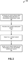
- FIG. 2 illustrates a flow diagram of one embodiment of VSLAM Initialization.
- the FVI may initialize a 3D target from a first reference image (e.g., a single reference image) and prior to processing a subsequent image.
- initializing a first image e.g., a single reference image captured from camera 114 may include determining a set of interest points in three-dimensional space with an initial estimated depth as described in further detail below.
- the initialization may occur immediately, in real-time, near real-time, or within a short time window of the reference image capture.
- the FVI may create a target from an initial captured reference image.
- the target as used herein may also be understood to be a model, or map of a 3D object or scene.
- the FVI may create a target from a single image from a single camera sensor or monocular source.
- the target may be stored in memory (e.g., in memory 164 of device 100) and represented by or associated with one or more 3D interest points extracted or calculated from an image.
- the 3D target may be initialized without any user input when selecting an initial reference image or a second reference image.
- the FVI may process one or more subsequent images. Processing may include determining a set of interest points within each of the subsequent images.
- the set of interest points may be the same interest points determined after processing the reference image, however the location and depth values may be different than the reference image.
- the FVI may track the 3D target in six degrees of freedom.
- the FVI may begin tracking a target (e.g., scene, object, or map) based on the first image frame received.
- tracking may occur immediately, instantaneously, in real-time, near real time, or within a short time period following the receipt by the FVI of the first single reference image.
- VSLAM initialization may be readily apparent to an augmented reality user because a 3D target may be initialized instantly, in real-time, near real time, or within a short time period of frame capture.
- the 3D target may be further refined when the user moves the camera 114 in any direction and additional images are received and processed.
- the FVI may display a representation of the target while tracking, as described in greater detail below.
- the FVI may refine the 3D target based on the processing of the one or more subsequent images.
- the FVI may determine whether the interest points may be estimated and incrementally refine the target over small movements.
- the FVI may provide a camera motion estimate for initial small motions by approximating the target to a plane having assumed depth values.
- the step of explicitly solving for epipolar geometry (which may be dependent on having enough translation) can be omitted.
- the FVI may initialize automatically and also provides continuous camera 114 tracking from the first reference image onwards.
- the FVI may also automatically select a second reference image from additional images recorded by camera 114 (e.g., subsequent image captures after the first initial referent image).
- the method of selecting the second reference image is described in further detail below. After a second reference image is selected tracking and camera 114 pose determination may continue based on the tracking and camera pose determination from the first and second reference image.
- the discovered image may automatically be assigned as a second reference image.
- the interest points from the second reference image may be used to triangulate the target resulting in a further increase in tracking accuracy.
- a device 100 may be able to automatically start, execute, or run (e.g., by using processor 161) the FVI (e.g., as an FVI engine, software process or other implementation) without any direct or manual user interaction or trigger.
- the FVI may cause device 100 to prompt a user to start initialization and tracking of a target by touching a touch screen, pressing a button, or similar input.
- the FVI may be integrated into an application or program and the application or program prompts the user or automatically captures an initial reference image and begins tracking.
- the first image may be an initial or first reference image.
- the device 100 may capture an initial image with camera 114 and send the image to the FVI for augmented reality processing.
- the initial image frame may be captured automatically by camera 114 when camera movement or motion is detected.
- a captured image may be a still/photographic image frame or a video frame.
- camera 114 may have video as well as still photo image capture capabilities.
- fast camera tracking starting from a first reference image is possible, at least in part, by processing a single first image (e.g., an initialization image captured from camera 114) and calculating a set of extracted interest points using an initial estimated depth.
- an augmented reality program or application may display registered content (graphics) in a scene (e.g., on a display for a mobile device or computer) from initialization onwards, before any camera 114 motion is received (e.g., camera translation).
- the FVI may also display registered content in a scene when only rotational motion is received.
- the FVI may create an accurate dataset for target tracking without requiring specific motions from the user to initialize tracking.
- the FVI may track a scene or object immediately and provide AR updates to the display (e.g., an augmentation of the target) in real-time, near real-time, instantaneously, or within a short time window.
- AR updates e.g., an augmentation of the target
- users are encouraged to continue to move/reposition the camera and explore a target or scene with the device camera 114. Greater exploration of a scene at different angles and viewpoints may uncover more information about the target.
- the FVI may use the additional information learned while the user moves the camera to refine the target.
- the FVI may provide real time display feedback using the refined target as a user moves the camera.
- a second reference image that may be used to further refine the FVI's collected information about a target and camera pose may be discovered and selected while providing real time display feedback.
- the FVI may optionally prompt the user for additional information to augment the target.
- the user may be able to add user created or selected content to the representation on the device 100 display.
- User content may be an image, 3D object, video, text, or other content type that may be integrated with, or overlaid with, or replacing a representation of the target.
- fast target tracking from a first reference image may be facilitated, at least in part, by processing a first image (e.g., an initialization image captured from camera 114) as an 3D target (e.g., as a planar or other geometric shaped 3D target).
- a first image e.g., an initialization image captured from camera 114
- an 3D target e.g., as a planar or other geometric shaped 3D target.
- an FVI automatically selects the parts (e.g., interest points) of a scene (e.g., 3D map) that may be updated given the observed camera 114 motion.
- the FVI may initialize automatically and provide continuous camera 114 tracking from the first reference image onwards to subsequently captured images.
- the FVI may also automatically select a second reference image from additional images recorded by camera 114 (e.g., subsequent image captures after the first initial referent image). After a second reference image is selected tracking and camera 114 pose determination may be further/fully refined based on the tracking and camera pose determination from the first and second reference image.
- the FVI may create an accurate dataset for 3D target tracking without a receiving any predetermined or pre-initialization input relating to a specific target shape, marker (real world or virtual) or tag.
- the FVI may initialize 3D targets without prior knowledge of the shape of the 3D target and without knowledge of the existence of specific features within the 3D target. For example, in one embodiment, instead of receiving a predefined target object or target with known coordinates, the FVI may initialize the 3D target and may set an equal depth to every discovered feature. Therefore, in one embodiments, the dataset for the 3D target may be fully populated with depth and location for all interest points from the first single reference image. Any errors in depth may be corrected as the camera pose changes with respect to the 3D target.
- an AR program or application may display registered content (graphics) in a scene (e.g., on a display for a mobile device or computer) from initialization onwards, before any camera 114 or rotational motion is received.
- the AR program may provide an AR representation of the target on the display of a mobile phone or handheld device.
- An interest point as used herein may be defined as an interesting or notable part of an image.
- Interest point detection may be a low-level image processing operation to examine every pixel to determine whether an interest point exists at a particular pixel.
- a high-level algorithm may also be used for interest point detection.
- Interest point detection may process an entire image frame or, alternatively subsections of the image.
- the interest points extracted from the image may represent distinct points along three-dimensional space (e.g., coordinates of axes X, Y, and Z).
- a target as used herein, may include interest points extracted from or associated with a single isolated object within an image, or multiple objects. For example, an entire scene captured in an image may include multiple objects and each object may have one or more extracted interest points. A group of objects within an image or scene may also have a collective combined interest point set associated with the entire group.
- the FVI's extraction of interest points with an initial estimated depth allows for tracking and camera pose determination for non-planar scenes (e.g., scenes that are not a single plane parallel to the initial reference image or image, but may be in a plane that is in an arbitrary position, or a different 3D surface, or scenes that have no dominant planar structure at all).
- non-planar scenes e.g., scenes that are not a single plane parallel to the initial reference image or image, but may be in a plane that is in an arbitrary position, or a different 3D surface, or scenes that have no dominant planar structure at all).
- a local image patch around the interest point may be extracted.
- Interest points may be extracted using a well-known technique, such as Scale Invariant Feature Transform (SIFT), which localizes interest points and generates their descriptions.
- SIFT Scale Invariant Feature Transform
- other techniques such as Speed Up Robust Features (SURF), Gradient Location-Orientation histogram (GLOH), or other comparable techniques may be used.
- SURF Speed Up Robust Features
- GLOH Gradient Location-Orientation histogram
- the image may be saved as a first reference image and the extracted interest points may be defined as reference points.
- the FVI may track a target without the use of any accelerometer data (e.g., the target may be in any orientation relative to gravity, and horizontal or vertically aligned objects are equally viable for FVI tracking).
- the FVI may track a target of any shape (e.g., the FVI does not rely upon a rectangular or another defined geometric structure in order to identify and track the target).
- the FVI may track a target even when the target is partially occluded. For example, the FVI may track a target that even when one or more portions of the target are missing or obscured from the initial reference frame. The FVI may update the target with additional discovered interest points as the camera is moved in 6DoF.
- the FVI may not require user input, nor rely on other tracking initialization methods to begin tracking a target.
- FVI tracking does not rely on the user to move the camera in particular motions, stand in a particular location, hold the camera horizontally, or perform other forms of tracking initialization methods before tracking the target.
- device 100 may be a portable electronic device (e.g., smart phone, dedicated augmented reality (AR) device, game device, wearable device such as eyeglasses, or other device with AR processing and display capabilities).
- the device implementing the AR system described herein may be used in a variety of environments, such as shopping malls, streets, rooms, or anywhere a user may take a portable device.
- a user may use the device 100 to view a representation of the target and real world through the display of their device.
- a user may interact with an AR capable device by using the device's camera to receive real world images/video and superimpose or overlay additional or alternate information onto the displayed real world images/video on the device.
- real world objects or scenes may be replaced or altered in real time on the device display.
- Virtual objects e.g., text, images, video
- a customized virtual photo may be inserted on top of a real world sign, poster or picture frame.
- a 3D virtual character e.g., a video game character
- a user's experience of an AR device may be greatly enhanced by automatically updating the AR displayed on the device as the user moves the device and without prior knowledge of the user's environment.
- FVI may operate without a map, CAD model, markers in the scene or similar.
- the FVI may also enhance a user's experience by providing visual feedback (e.g., AR updates to the target represented on the display 112) without multiple different and precise image captures.
- visual updates to the AR system may be provided to the display and user in real-time, near real-time, almost instantaneously, or within a short time window of capturing the first reference image.
- the FVI may provide interactive feedback to the user of how augmentations will be anchored to a selected point in the environment, as soon as the user points the camera at the point. For example, upon initialization on a device, the FVI may allow a user to automatically select a target merely by pointing the camera at the target.
- Movement of the device 100 and camera 114 may cause the display to update, in real-time, an augmentation of the target (e.g., one or more objects or scenes) being tracked.
- the device With movement of the device away from an initial reference image position, the device may capture additional images from alternate views. As the alternate views are displayed, scene augmentation may become more accurate while the FVI processes the additional images.
- the FVI may estimate 3D position of extracted interest points associated with the target to obtain 3D knowledge of the environment the camera is looking at. Using a vision-based solution for tracking interest points, local normal vectors and relative distances between points may be inferred.
- an object or graphic may be inserted or integrated into a video stream (or image) captured by the camera 114 and displayed on display 112.
- the display may, in some embodiments, update in real-time with seamless tracking from the original scene. For example, text on a sign may be replaced with alternate text, or a 3D object may be strategically placed in the scene and displayed on device 100.
- the graphic or object may be adjusted or augmented to match the relative movement of the camera 114.
- the FVI may cast a ray from the camera in the camera view direction into an estimated dominant plane (e.g., the plane initialized at the initial depth described above).
- the FVI may estimate the direction of gravity using the accelerometer, and wherever the camera is pointed, use the direction of gravity in addition to the ray cast from the camera, to correctly align, position, and distance a 3D augmentation of the target for display. For example, if a virtual object is inserted into an augmented reality display, camera movement away from the virtual object may reduce the size of the virtual object relative to the distance traveled by the camera 114. For example, taking four steps back from a virtual object should cause a greater reduction in size of the virtual object compared to taking a half step back from the virtual object, all other variables being equal.
- Motion graphics or animation may be animated within the scene represented by the FVI. For example, an animated object may "move" within a scene depicted in the augmented reality display.
- the FVI may select an appropriate image to be used as a second reference image.
- the second reference image may be selected from an image feed or stream.
- increased accuracy of the augmentation may be achieved (e.g., borders around an object may fit more precisely, the representation of the object in the scene will appear more realistic, and target placement may be more accurate relative to the camera 114 pose).
- the FVI may be implemented as an engine or module executed by a processor to receive images or video as input.
- the FVI may begin with receiving a single image I 0 .
- the camera position C t is estimated from measurements of the 2D locations of the 3D points X i .
- the points X i are reprojected into the current image I t using the last known camera pose C t -1 and new measurements of the 2D location in image I t may be made.
- the new measurements of the 2D location in image I t may be obtained using normalized cross correlation between image patches taken from image I 0 , or another method of obtaining image correspondences. Using such a method, a 2D location m i can be observed for each point X i . Then, both the camera location C t as well as the inverse depth w i of each point can be optimized using a Gauss-Newton non-linear refinement scheme.
- the Jacobian J w of the observation m i with respect to the inverse depth w i of the 3D point vanishes (becomes small and almost zero) which can preclude an accurate estimation of the inverse depth. Therefore, during the Gauss-Newton iteration, for each point the information matrix J w T J w of the inverse depth parameter is tested.
- the information matrix is in this case only a non-negative scalar value; if it is below a threshold, such as 10 -3 , its inverse is set to 0. Setting the inverse to 0 avoids updating the depth coordinate, because this cannot be done reliably in this case.
- the FVI can always estimate the camera pose, because the points X i have known depth coordinates. Therefore, in one embodiment, the camera parameter part of the optimization is always well constrained.
- Optimizing and updating both camera pose parameters and the inverse depth coordinates w i of all points can result in a new camera pose C t and new depth estimates for all points for which the Jacobians did not vanish.
- FIG. 3 illustrates a flow diagram of one embodiment of Fast VSLAM Initialization.
- the FVI may read or receive an image to use as a reference image.
- the reference image may be an initial captured image from a camera sensor/image feed, or may be selected by a user.
- the FVI can initialize a 3D target without any user input for selecting an initial image.
- building the 3D target is initiated when the camera 114 moves in any direction.
- the reference image can be a starting point for continuously estimating a target's true/refined shape as the camera 114 moves in 6DoF and captures subsequent images.
- a user can move the camera 114 in any direction and tracking and initialization of the 3D target may be performed when the original scene stays at least partially visible.
- an assumed depth value camera tracking may be performed instantly, in real-time, near real-time, or within a short time window from the first image (reference image) onwards.
- the FVI may determine a set of 3D interest points from the reference image using one of the methods described above.
- the FVI may set the target to a geometric shape.
- the geometric shape may take the form of a plane, however, other shapes may be used to set the target.
- the FVI may assign each of the 3D interest points to a same/equal fixed depth value.
- the interest points may initially lie along a 2D plane parallel to the image plane.
- the assumption that all 3D interest points are on a plane parallel to the image plane facilitates real-time, near real-time, or fast tracking of the target with incremental refinement as the 3D point depths are updated.
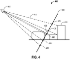
- FIG. 4 illustrates one embodiment of a side schematic view of a camera capturing an image of target initialized with a plane.
- FIG. 4 also interest points of a target (e.g., interest points 425, 430, 435, 440, 445, and 450) set to plane 420 at a predefined initial distance, as viewed from camera 114 at position 405.
- the interest points may be initialized with any other geometric shape, or any arrangement of initialized depth values.
- the FVI may determine that another geometric shape should be the baseline starting point for the target, and refine as more target information is discovered.
- the initialized depth values may be individually estimated or determined by other techniques as known in the art.
- the initial depth values may be a range of values such that the average interest point depth falls within a predetermined threshold average depth.
- FIG. 4 also illustrates objects (e.g., object 410) representing the 3D scene observed by camera 114.
- Line 415 illustrates the ray under which an interest point 425 associated with object 410 is seen (e.g., the interest point 425 associated with the edge of object 410 has an initial equal depth as other interest points detected along the plane 420). The distance from camera 114 at position 405 to interest point 425 along line 415 is the assumed depth of interest point 425.
- the FVI can begin processing a subsequent image.
- camera 114 can continue to capture and process one or more of subsequent images of the target from different viewpoints.
- the subsequent image(s) may immediately follow the reference image.
- the subsequent image(s) may be captured from a stream of images and captured at any later time after the reference image (e.g., other images may be captured immediately between the reference image and a subsequent image).
- Processing a subsequent image can include extracting or determining a set of 3D interest points within the subsequent image.
- the set of 3D interest points in the subsequent image(s) may be the same or equivalent to 3D interest points determined from the reference image, except the 3D interest points in the subsequent image(s) may be at a different depth or location compared to the reference image.
- the FVI may start processing subsequent images immediately after determination of the reference image, or alternatively, may delay processing until two or more images have been detected (e.g., within a camera feed).
- the camera 114 may capture images at 30 frames per second, however the FVI may determine that the 5 immediately subsequent frames (e.g., or frames captured within a period of time immediately following the capture of the initial reference image) are unlikely to result in measurable camera translation. Therefore, in some embodiments, the FVI may bypass a one or more subsequent frames or a period of time subsequent to the initial reference frames may be bypassed.
- the FVI may not always process every image in an image feed in order to reduce overall processing time. For example, the FVI may use a sample of the feed of images (e.g., every other recorded image, or one in every five recorded images) to process for interest points.
- the FVI can track the interest points of the subsequent image.
- tracking the target includes comparing locations of each 3D interest point from the reference image with a corresponding 3D interest point from the subsequent image and determining a change in location of one or more of the same 3D interest points found in both images.
- the FVI may determine whether the subsequent image is a candidate for assignment as a second reference image as disclosed in greater detail below.
- the plane approximation reduces or eliminates tracking errors such that any remaining errors are largely unnoticed by a user.
- the first plane approximation of the scene can be accurate enough that tracking errors are not noticeable. Images resulting from these small movements would not be used as the subsequent reference image, however, this promotes further scene exploration by the user until a second reference image is obtained to further reduce any errors.
- FIG. 5 One embodiment of small movement tracking with a plane is illustrated in FIG. 5 as side schematic view of small movement 510 from camera position 405 to camera position 505. As illustrated in FIG. 5 , the ray lines and interest points may initially diverge with small movement 510 from camera position 405.
- FIG. 6 illustrates one embodiment of a side schematic view of a camera capturing an image of a scene and a large motion 610 by the camera from position 405 to new camera position 615.
- FIG. 6 illustrates the ray 415 previously associated with interest point 425, becomes ray 620, and no longer accurately tracks the interest point 425.
- the FVI can determine whether each interest point depth, i.e. a 3D point location, can be estimated. 3D point estimation respects the epipolar constraint because it jointly estimates camera motion and all possible 3D points. As discussed above, for each interest point the information matrix J w T J w of the inverse depth parameter is tested to determine if the depth of an interest point can be estimated. If an interest point depth cannot be estimated, the FVI may proceed to block 340 and add a camera constraint. Otherwise, if an interest point can be estimated, the estimated interest point is added to a list of updated points at block 335.
- the estimated interest point may update a main storage location (e.g., database, flat file, or other storage type) for the interest points instead of maintaining a separate list or location for updated points.
- the FVI may proceed to block 340 to add a camera constraint for the interest point.
- Constraints as used herein are the linear constraints given by the Jacobians and the observed 2D measurement. See above for the detailed discussion of the projection function and Jacobians with respect to R, T, and w .
- the FVI can optimize camera and target.
- the FVI optimizes the camera 114 and target based on movements of the camera 114.
- the display can provide updates to the user in real time. Receiving real time feedback can encourage a user to continue moving the camera 114. Additional camera movement can provide further refinement of the target and greater accuracy in tracking.
- device 100 may display an integrated graphic or object with the target and the graphic or object can be positioned in the scene such that when the camera is moved (e.g., in one of 6DoF) the graphic or object maintains its relative position to other objects or the environment (relative to their positions and orientations as determined from the first reference image).
- the FVI can determine whether enough points have been estimated.
- a threshold for the number of points is set through testing the method in different scenes, for example the threshold may be set based on design and system parameters. In one embodiment, the threshold may be set at 100 points, or alternatively 150 points, or some other number. If there have been enough points, the FVI may proceed to block 355. In one embodiment, when the threshold number of points is met, the FVI can assign the image associated with the points as the second reference image and proceed to block 355. Otherwise, the FVI continues to process a subsequent image at block 320. In one embodiment, the FVI can iterate through multiple subsequent images (e.g., from a series of image frames captured from camera 114) processing each image while determining if enough interest points have been estimated.
- the FVI can be determined as complete and increased accuracy tracking is provided for subsequent images.
- the FVI can triangulate interest point locations from the first and second reference image.
- the two reference images may depict the same target (e.g., a section of an object or scene) from different viewing directions.
- the FVI may find correspondences (i.e., interest point locations in both the first and second images) and calculate the 3D structure of these corresponding interest points along with the motion that moved the camera from the first reference image to the second reference image.
- the triangulation of the interest points may be considered a second level of refinement after the initial small motion refinements described above. The triangulation can occur after two reference images are determined.
- FIG. 7 illustrates as side schematic view of a camera 405 after large camera movement and after a second reference image allows for more accurate (i.e. updated) interest point depths for each of a set of points 725, 735, 745, 750, 740, and 760 observed by the camera 114 (615).
- Line 620 illustrates the ray under which an updated interest point 760 is seen.
- the teachings herein may be incorporated into (e.g., implemented within or performed by) a variety of apparatuses (e.g., devices).
- a phone e.g., a cellular phone
- PDA personal data assistant
- a tablet e.g., a mobile computer, a laptop computer, a tablet
- an entertainment device e.g., a music or video device
- a headset e.g., headphones, an earpiece, etc.
- a medical device e.g., a biometric sensor, a heart rate monitor, a pedometer, an EKG device, etc.
- a user I/O device e.g., a computer, a server, a point-of-sale device, an entertainment device, a set-top box, or any other suitable device.
- These devices may have different power and data requirements and may result in different power profiles generated for each interest point or set of interest points.
- a wireless device may comprise an access device (e.g., a Wi-Fi access point) for a communication system.
- an access device may provide, for example, connectivity to another network through transceiver 140 (e.g., a wide area network such as the Internet or a cellular network) via a wired or wireless communication link.
- the access device may enable another device (e.g., a Wi-Fi station) to access the other network or some other functionality.
- the devices may be portable or, in some cases, relatively non-portable.
- DSP digital signal processor
- ASIC application specific integrated circuit
- FPGA field programmable gate array
- a general-purpose processor may be a microprocessor, but in the alternative, the processor may be any conventional processor, controller, microcontroller, or state machine.
- a processor may also be implemented as a combination of computing devices, e.g., a combination of a DSP and a microprocessor, a plurality of microprocessors, one or more microprocessors in conjunction with a DSP core, or any other such configuration.
- the steps of a method or algorithm described in connection with the embodiments disclosed herein may be embodied directly in hardware, in software executed by a processor, or in a combination of the two.
- Software may reside in RAM memory, flash memory, ROM memory, EPROM memory, EEPROM memory, registers, hard disk, a removable disk, a CD-ROM, or any other form of storage medium known in the art.
- An exemplary storage medium is coupled to the processor such the processor can read information from, and write information to, the storage medium.
- the storage medium may be integral to the processor.
- the processor and the storage medium may reside in an ASIC.
- the ASIC may reside in a user terminal.
- the processor and the storage medium may reside as discrete components in a user terminal.
- the functions or modules described may be implemented in hardware (e.g., hardware 162), software (e.g., software 165), firmware (e.g., firmware 163), or any combination thereof. If implemented in software as a computer program product, the functions or modules may be stored on or transmitted over as one or more instructions or code on a non-transitory computer-readable medium.
- Computer-readable media can include both computer storage media and communication media including any medium that facilitates transfer of a computer program from one place to another.
- a storage media may be any available media that can be accessed by a computer.
- non-transitory computer-readable media can comprise RAM, ROM, EEPROM, CD-ROM or other optical disk storage, magnetic disk storage or other magnetic storage devices, or any other medium that can be used to carry or store desired program code in the form of instructions or data structures and that can be accessed by a computer. Also, any connection is properly termed a computer-readable medium.
- Disk and disc includes compact disc (CD), laser disc, optical disc, digital versatile disc (DVD), floppy disk and blu-ray disc where disks usually reproduce data magnetically, while discs reproduce data optically with lasers. Combinations of the above should also be included within the scope of non-transitory computer-readable media.
Landscapes
- Engineering & Computer Science (AREA)
- Physics & Mathematics (AREA)
- General Physics & Mathematics (AREA)
- Theoretical Computer Science (AREA)
- Computer Vision & Pattern Recognition (AREA)
- Multimedia (AREA)
- Processing Or Creating Images (AREA)
- User Interface Of Digital Computer (AREA)
- Image Analysis (AREA)
- Image Generation (AREA)
- Image Processing (AREA)
- Studio Devices (AREA)
Claims (11)
- Procédé mis en oeuvre par processeur pour une localisation et cartographie simultanées visuelle, le procédé comprenant les étapes ci-dessous consistant à :initialiser (205, 210) une cible tridimensionnelle, 3D, sur la base d'un premier ensemble (425, 430, 435, 440, 445, 450) de points 3D cibles obtenus à partir d'une première image de référence, dans lequel les points 3D cibles dans le premier ensemble sont initialisés le long d'un plan (420), à une valeur de profondeur initiale prédéterminée, avant le traitement d'une image subséquente, dans lequel l'étape d'initialisation de la cible 3D comprend les étapes consistant à extraire un ensemble de référence de points d'intérêt 2D de l'image de référence, à déterminer les points 3D cibles, chaque point 3D cible correspondant à un point d'intérêt 2D dans l'ensemble de référence de points d'intérêt 2D, et à affecter la valeur de profondeur initiale prédéterminée à chaque point 3D cible ;traiter (210, 320), sur la base de la première image de référence avant l'obtention d'une seconde image de référence, une ou plusieurs images subséquentes, de manière conjointe :en suivant (215, 325) la cible 3D sur six degrés de liberté ; eten affinant (220) la cible 3D sur la base d'ensembles subséquents de points 3D cibles obtenus à partir du traitement de ladite une ou desdites plusieurs images subséquentes reçues subséquemment à la première image de référence, chaque ensemble subséquent de points 3D cibles correspondant à une image de ladite une ou desdites plusieurs images subséquentes, caractérisé par les étapes ci-dessous consistant à :déterminer une valeur de profondeur mise à jour pour un ou plusieurs des points 3D cibles dans le premier ensemble, sur la base de points 3D correspondants dans un ensemble subséquent ; etremplacer la valeur de profondeur initiale prédéterminée affectée pour chaque point dudit un ou desdits plusieurs points 3D cibles par la valeur de profondeur mise à jour correspondante.
- Procédé mis en oeuvre par processeur selon la revendication 1, comprenant en outre l'étape ci-dessous consistant à :
afficher une représentation en réalité augmentée, correctement alignée, positionnée et distanciée, de la cible 3D, suite à l'initialisation de la cible 3D. - Procédé mis en oeuvre par processeur selon la revendication 2, comprenant en outre l'étape ci-dessous consistant à :
mettre à jour la représentation en réalité augmentée de la cible 3D tout en suivant la cible 3D sur six degrés de liberté. - Procédé mis en oeuvre par processeur selon la revendication 1, dans lequel l'étape de traitement d'une ou plusieurs images subséquentes comprend en outre l'étape ci-dessous consistant à :
extraire des points d'intérêt 2D de ladite une ou desdites plusieurs images subséquentes. - Procédé mis en oeuvre par processeur selon l'une quelconque des revendications précédentes, dans lequel l'étape de suivi de la cible 3D comprend en outre l'étape consistant à comparer un emplacement de référence correspondant à au moins l'un des points 3D cibles à un emplacement 2D mis à jour correspondant dudit au moins un point 3D cible extrait de ladite une ou desdites plusieurs images subséquentes.
- Procédé mis en oeuvre par processeur selon la revendication 1, comprenant en outre les étapes ci-dessous consistant à :déterminer le moment où est atteint un nombre seuil des points 3D cibles présentant une valeur de profondeur mise à jour, dans lequel le nombre seuil de points 3D cibles est obtenu à partir d'une image subséquente respective correspondante de ladite une ou desdites plusieurs images subséquentes ; etaffecter l'image subséquente respective en tant que la seconde image de référence.
- Procédé mis en oeuvre par processeur selon la revendication 6, dans lequel l'étape consistant à affiner la cible 3D comprend en outre l'étape consistant à mettre en oeuvre un affinement supplémentaire de la cible 3D par la triangulation des points 3D cibles avec une pluralité de points d'intérêt 2D extraits de la seconde image de référence.
- Support de stockage lisible par ordinateur non transitoire contenant des instructions de programme exécutables qui amènent un dispositif de traitement de données à mettre en oeuvre le procédé selon l'une quelconque des revendications 1 à 7.
- Appareil pour une localisation et cartographie simultanées visuelle, comprenant :un moyen pour initialiser (205, 210) une cible tridimensionnelle, 3D, sur la base d'un premier ensemble (425, 430, 435, 440, 445, 450) de points 3D cibles obtenus à partir d'une première image de référence, dans lequel les points 3D cibles dans le premier ensemble sont initialisés le long d'un plan (420), à une valeur de profondeur initiale prédéterminée, avant le traitement d'une image subséquente, dans lequel le moyen d'initialisation de la cible 3D comprend : un moyen pour extraire un ensemble de référence de points d'intérêt 2D de la première image de référence ; un moyen pour déterminer les points 3D cibles, chaque point 3D cible correspondant à un point d'intérêt 2D dans l'ensemble de référence de points d'intérêt 2D ; et un moyen pour affecter la valeur de profondeur initiale prédéterminée à chaque point 3D cible correspondant à un point d'intérêt 2D dans l'ensemble de référence de points d'intérêt 2D ;un moyen pour traiter (210, 320), sur la base de la première image de référence avant l'obtention d'une seconde image de référence, une ou plusieurs images subséquentes, comprenant :
un moyen pour, de manière conjointe, suivre (215, 325) la cible 3D sur six degrés de liberté, et affiner (220) la cible 3D sur la base d'ensembles subséquents de points 3D cibles obtenus à partir du traitement de ladite une ou desdites plusieurs images subséquentes reçues subséquemment à la première image de référence, chaque ensemble subséquent de points 3D cibles correspondant à une image de ladite une ou desdites plusieurs images subséquentes, le moyen d'affinement étant en outre caractérisé par :un moyen pour déterminer une valeur de profondeur mise à jour pour un ou plusieurs des points 3D cibles dans le premier ensemble, sur la base de points 3D correspondants dans un ensemble subséquent ; etun moyen pour remplacer la valeur de profondeur initiale prédéterminée affectée pour chaque point dudit un ou desdits plusieurs points 3D cibles par la valeur de profondeur mise à jour correspondante. - Appareil selon la revendication 9, dans lequel le moyen pour suivre la cible 3D de manière conjointe comprend en outre un moyen pour comparer un emplacement de référence correspondant à au moins l'un des points 3D cibles dans l'ensemble de référence à un emplacement 2D mis à jour correspondant dudit au moins un point 3D cible extrait de ladite une ou desdites plusieurs images subséquentes.
- Appareil selon la revendication 9, comprenant en outre :un moyen pour déterminer le moment où est atteint un nombre seuil des points 3D cibles présentant des valeurs de profondeur mises à jour, dans lequel le nombre seuil de points 3D cibles est obtenu à partir d'une image subséquente correspondante de ladite une ou desdites plusieurs images subséquentes ; etun moyen pour affecter l'image subséquente respective en tant que la seconde image de référence.
Applications Claiming Priority (3)
| Application Number | Priority Date | Filing Date | Title |
|---|---|---|---|
| US201261722091P | 2012-11-02 | 2012-11-02 | |
| US13/831,405 US9576183B2 (en) | 2012-11-02 | 2013-03-14 | Fast initialization for monocular visual SLAM |
| PCT/US2013/065654 WO2014070483A1 (fr) | 2012-11-02 | 2013-10-18 | Initialisation rapide pour slam visuel monoculaire |
Publications (2)
| Publication Number | Publication Date |
|---|---|
| EP2915140A1 EP2915140A1 (fr) | 2015-09-09 |
| EP2915140B1 true EP2915140B1 (fr) | 2018-10-17 |
Family
ID=50622422
Family Applications (1)
| Application Number | Title | Priority Date | Filing Date |
|---|---|---|---|
| EP13786367.6A Active EP2915140B1 (fr) | 2012-11-02 | 2013-10-18 | Initialisation rapide pour slam visuel monoculaire |
Country Status (8)
| Country | Link |
|---|---|
| US (1) | US9576183B2 (fr) |
| EP (1) | EP2915140B1 (fr) |
| JP (1) | JP6258953B2 (fr) |
| KR (1) | KR20150082379A (fr) |
| CN (1) | CN104781849B (fr) |
| BR (1) | BR112015009521A2 (fr) |
| TW (1) | TWI509221B (fr) |
| WO (1) | WO2014070483A1 (fr) |
Families Citing this family (65)
| Publication number | Priority date | Publication date | Assignee | Title |
|---|---|---|---|---|
| US9135705B2 (en) * | 2012-10-16 | 2015-09-15 | Qualcomm Incorporated | Sensor calibration and position estimation based on vanishing point determination |
| US20140270477A1 (en) * | 2013-03-14 | 2014-09-18 | Jonathan Coon | Systems and methods for displaying a three-dimensional model from a photogrammetric scan |
| US20140369557A1 (en) * | 2013-06-14 | 2014-12-18 | Qualcomm Incorporated | Systems and Methods for Feature-Based Tracking |
| US20150092048A1 (en) | 2013-09-27 | 2015-04-02 | Qualcomm Incorporated | Off-Target Tracking Using Feature Aiding in the Context of Inertial Navigation |
| CN105825520A (zh) * | 2015-01-08 | 2016-08-03 | 北京雷动云合智能技术有限公司 | 一种可创建大规模地图的单眼slam方法 |
| EP3062142B1 (fr) | 2015-02-26 | 2018-10-03 | Nokia Technologies OY | Appareil pour un dispositif d'affichage proche |
| CN104867158B (zh) * | 2015-06-03 | 2017-09-29 | 武汉理工大学 | 基于单目视觉的室内水面船舶精确定位系统和方法 |
| GB2541884A (en) | 2015-08-28 | 2017-03-08 | Imp College Of Science Tech And Medicine | Mapping a space using a multi-directional camera |
| CN107025661B (zh) * | 2016-01-29 | 2020-08-04 | 成都理想境界科技有限公司 | 一种实现增强现实的方法、服务器、终端及系统 |
| CN107665508B (zh) * | 2016-07-29 | 2021-06-01 | 成都理想境界科技有限公司 | 实现增强现实的方法及系统 |
| EP3504682B1 (fr) * | 2016-08-24 | 2020-07-15 | Universität Zürich | Localisation et cartographie simultanées avec caméra basée sur des événements |
| CN106197432B (zh) * | 2016-08-30 | 2018-12-21 | 北京航空航天大学 | 一种基于FastSLAM算法的无人机着陆方法 |
| EP3306572A1 (fr) * | 2016-10-07 | 2018-04-11 | Schneider Electric Industries SAS | Procédé de mappage 3d de point d'intérêt 2d |
| CN106570913B (zh) * | 2016-11-04 | 2019-12-13 | 上海玄彩美科网络科技有限公司 | 基于特征的单目slam快速初始化方法 |
| US10430685B2 (en) * | 2016-11-16 | 2019-10-01 | Facebook, Inc. | Deep multi-scale video prediction |
| US10650552B2 (en) | 2016-12-29 | 2020-05-12 | Magic Leap, Inc. | Systems and methods for augmented reality |
| EP3343267B1 (fr) | 2016-12-30 | 2024-01-24 | Magic Leap, Inc. | Appareil de découplage de lumière polychromatique, affichages proches de l' il le comprenant et procédé de découplage de lumière polychromatique |
| US20200158517A1 (en) * | 2017-01-19 | 2020-05-21 | Mindmaze Holding Sa | System, methods, device and apparatuses for preforming simultaneous localization and mapping |
| WO2018134686A2 (fr) * | 2017-01-19 | 2018-07-26 | Mindmaze Holding Sa | Systèmes, procédés, dispositif et appareils pour effectuer une localisation et une cartographie simultanées |
| AU2018209336B2 (en) | 2017-01-23 | 2021-11-18 | Oxford University Innovation Limited | Determining the location of a mobile device |
| AU2018208816B2 (en) | 2017-01-23 | 2022-06-16 | Oxford University Innovation Limited | Determining the location of a mobile device |
| US10659768B2 (en) * | 2017-02-28 | 2020-05-19 | Mitsubishi Electric Research Laboratories, Inc. | System and method for virtually-augmented visual simultaneous localization and mapping |
| US10489965B1 (en) * | 2017-03-24 | 2019-11-26 | Mappedin Inc. | Systems and methods for positioning a virtual camera |
| US10848741B2 (en) * | 2017-06-12 | 2020-11-24 | Adobe Inc. | Re-cinematography for spherical video |
| US10578870B2 (en) | 2017-07-26 | 2020-03-03 | Magic Leap, Inc. | Exit pupil expander |
| WO2019019157A1 (fr) | 2017-07-28 | 2019-01-31 | Qualcomm Incorporated | Initialisation de capteur d'image dans un véhicule robotisé |
| US11551368B2 (en) * | 2017-08-31 | 2023-01-10 | Sony Group Corporation | Electronic devices, methods, and computer program products for controlling 3D modeling operations based on pose metrics |
| US10497145B2 (en) * | 2017-11-16 | 2019-12-03 | Nec Corporation | System and method for real-time large image homography processing |
| AU2018379105B2 (en) | 2017-12-10 | 2023-12-21 | Magic Leap, Inc. | Anti-reflective coatings on optical waveguides |
| CN111712751B (zh) | 2017-12-20 | 2022-11-01 | 奇跃公司 | 用于增强现实观看设备的插入件 |
| US10402986B2 (en) * | 2017-12-20 | 2019-09-03 | Facebook, Inc. | Unsupervised video segmentation |
| US10311646B1 (en) * | 2018-02-26 | 2019-06-04 | Capital One Services, Llc | Dynamic configuration of an augmented reality overlay |
| AU2019227833A1 (en) * | 2018-03-01 | 2020-10-22 | Lappidus, Inc | Virtual asset tagging and augmented camera display system and method of use |
| WO2019178567A1 (fr) | 2018-03-15 | 2019-09-19 | Magic Leap, Inc. | Correction d'image due à la déformation de composants d'un dispositif de visualisation |
| CN110264509B (zh) * | 2018-04-27 | 2022-10-14 | 腾讯科技(深圳)有限公司 | 确定图像捕捉设备的位姿的方法、装置及其存储介质 |
| JP2021525902A (ja) | 2018-05-30 | 2021-09-27 | マジック リープ, インコーポレイテッドMagic Leap,Inc. | 小型の可変焦点構成 |
| JP7319303B2 (ja) | 2018-05-31 | 2023-08-01 | マジック リープ, インコーポレイテッド | レーダ頭部姿勢位置特定 |
| US10825424B2 (en) | 2018-06-05 | 2020-11-03 | Magic Leap, Inc. | Homography transformation matrices based temperature calibration of a viewing system |
| US11092812B2 (en) | 2018-06-08 | 2021-08-17 | Magic Leap, Inc. | Augmented reality viewer with automated surface selection placement and content orientation placement |
| WO2020010097A1 (fr) | 2018-07-02 | 2020-01-09 | Magic Leap, Inc. | Modulation d'intensité de pixel en utilisant la modification de valeurs de gain |
| US11510027B2 (en) | 2018-07-03 | 2022-11-22 | Magic Leap, Inc. | Systems and methods for virtual and augmented reality |
| US11856479B2 (en) | 2018-07-03 | 2023-12-26 | Magic Leap, Inc. | Systems and methods for virtual and augmented reality along a route with markers |
| WO2020023543A1 (fr) | 2018-07-24 | 2020-01-30 | Magic Leap, Inc. | Dispositif de visualisation à intégrant un joint anti-poussière |
| US11598651B2 (en) | 2018-07-24 | 2023-03-07 | Magic Leap, Inc. | Temperature dependent calibration of movement detection devices |
| EP3831058A4 (fr) | 2018-08-02 | 2022-04-20 | Magic Leap, Inc. | Système de visualisation avec compensation de distance interpupillaire basée sur le mouvement de la tête |
| CN112789544B (zh) | 2018-08-03 | 2023-06-30 | 奇跃公司 | 图腾在用户交互系统中的融合姿势的基于未融合姿势的漂移校正 |
| CN113196138B (zh) | 2018-11-16 | 2023-08-25 | 奇跃公司 | 用于保持图像清晰度的图像尺寸触发的澄清 |
| CN109917644B (zh) * | 2018-12-26 | 2022-06-14 | 达闼科技(北京)有限公司 | 一种提高视觉惯导系统鲁棒性的方法、装置和机器人设备 |
| CN109493685B (zh) * | 2018-12-29 | 2021-03-30 | 深圳市掌网科技股份有限公司 | 一种基于增强现实的虚拟打击乐器训练系统 |
| JP2022519292A (ja) | 2019-02-06 | 2022-03-22 | マジック リープ, インコーポレイテッド | 複数のプロセッサによって発生される総熱を限定するための標的意図ベースのクロック速度の決定および調節 |
| WO2020185405A1 (fr) | 2019-03-12 | 2020-09-17 | Magic Leap, Inc. | Enregistrement d'un contenu local entre des premier et second visualiseurs de réalité augmentée |
| WO2020198134A1 (fr) * | 2019-03-22 | 2020-10-01 | Vergence Automation, Inc. | Système de capteur invariant à l'éclairage pour la détection, la reconnaissance et l'évaluation d'objets |
| US10955245B2 (en) * | 2019-04-30 | 2021-03-23 | Samsung Electronics Co., Ltd. | System and method for low latency, high performance pose fusion |
| EP3963565A4 (fr) | 2019-05-01 | 2022-10-12 | Magic Leap, Inc. | Système et procédé de fourniture de contenu |
| CN110321902B (zh) * | 2019-05-09 | 2021-07-13 | 哈尔滨工业大学 | 一种基于socp的室内自动视觉指纹采集方法 |
| CN110298884B (zh) * | 2019-05-27 | 2023-05-30 | 重庆高开清芯科技产业发展有限公司 | 一种适于动态环境中单目视觉相机的位姿估计方法 |
| CN112215880B (zh) * | 2019-07-10 | 2022-05-06 | 浙江商汤科技开发有限公司 | 一种图像深度估计方法及装置、电子设备、存储介质 |
| CN112243082B (zh) * | 2019-07-17 | 2022-09-06 | 百度时代网络技术(北京)有限公司 | 一种跟踪拍摄方法、装置、电子设备及存储介质 |
| CN114174895A (zh) | 2019-07-26 | 2022-03-11 | 奇跃公司 | 用于增强现实的系统和方法 |
| US11514594B2 (en) | 2019-10-30 | 2022-11-29 | Vergence Automation, Inc. | Composite imaging systems using a focal plane array with in-pixel analog storage elements |
| WO2021097323A1 (fr) | 2019-11-15 | 2021-05-20 | Magic Leap, Inc. | Système de visualisation à utiliser dans un environnement chirurgical |
| US11340696B2 (en) * | 2020-01-13 | 2022-05-24 | Sony Interactive Entertainment Inc. | Event driven sensor (EDS) tracking of light emitting diode (LED) array |
| US11315346B2 (en) * | 2020-01-16 | 2022-04-26 | Square Enix Co., Ltd. | Method for producing augmented reality image |
| US11113894B1 (en) * | 2020-09-11 | 2021-09-07 | Microsoft Technology Licensing, Llc | Systems and methods for GPS-based and sensor-based relocalization |
| TWI772177B (zh) * | 2021-09-10 | 2022-07-21 | 迪伸電子股份有限公司 | 自走裝置的移動控制方法及自走裝置 |
Family Cites Families (21)
| Publication number | Priority date | Publication date | Assignee | Title |
|---|---|---|---|---|
| US5889505A (en) | 1996-04-04 | 1999-03-30 | Yale University | Vision-based six-degree-of-freedom computer input device |
| US6288704B1 (en) | 1999-06-08 | 2001-09-11 | Vega, Vista, Inc. | Motion detection and tracking system to control navigation and display of object viewers |
| US7774158B2 (en) | 2002-12-17 | 2010-08-10 | Evolution Robotics, Inc. | Systems and methods for landmark generation for visual simultaneous localization and mapping |
| US20080310757A1 (en) * | 2007-06-15 | 2008-12-18 | George Wolberg | System and related methods for automatically aligning 2D images of a scene to a 3D model of the scene |
| JP5012615B2 (ja) * | 2008-03-27 | 2012-08-29 | ソニー株式会社 | 情報処理装置、および画像処理方法、並びにコンピュータ・プログラム |
| US8970690B2 (en) | 2009-02-13 | 2015-03-03 | Metaio Gmbh | Methods and systems for determining the pose of a camera with respect to at least one object of a real environment |
| WO2010142929A1 (fr) * | 2009-06-11 | 2010-12-16 | Toshiba Research Europe Limited | Génération d'image tridimensionnelle |
| JP5683851B2 (ja) | 2009-08-20 | 2015-03-11 | 株式会社ザクティ | 撮像装置及び画像処理装置 |
| IL202460A (en) * | 2009-12-01 | 2013-08-29 | Rafael Advanced Defense Sys | Method and system for creating a 3D view of real arena for military planning and operations |
| KR101633620B1 (ko) * | 2010-01-04 | 2016-06-27 | 삼성전자 주식회사 | 영상 기반의 위치 인식을 위한 특징점 등록 장치 및 그 방법 |
| JP2011159163A (ja) * | 2010-02-02 | 2011-08-18 | Sony Corp | 画像処理装置、画像処理方法及びプログラム |
| FR2960082B1 (fr) * | 2010-05-17 | 2012-08-10 | Commissariat Energie Atomique | Procede et systeme pour fusionner des donnees issues de capteurs d'images et de capteurs de mouvement ou de position |
| JP5612916B2 (ja) * | 2010-06-18 | 2014-10-22 | キヤノン株式会社 | 位置姿勢計測装置、その処理方法、プログラム、ロボットシステム |
| US8913056B2 (en) | 2010-08-04 | 2014-12-16 | Apple Inc. | Three dimensional user interface effects on a display by using properties of motion |
| US8532367B2 (en) * | 2010-08-17 | 2013-09-10 | Raytheon Company | System and method for 3D wireframe reconstruction from video |
| JP5743501B2 (ja) | 2010-11-25 | 2015-07-01 | キヤノン株式会社 | 物体追尾装置、物体追尾方法、及び物体追尾プログラム |
| US8570320B2 (en) * | 2011-01-31 | 2013-10-29 | Microsoft Corporation | Using a three-dimensional environment model in gameplay |
| JP2012181688A (ja) | 2011-03-01 | 2012-09-20 | Sony Corp | 情報処理装置、情報処理方法、情報処理システムおよびプログラム |
| WO2013126784A2 (fr) * | 2012-02-23 | 2013-08-29 | Huston Charles D | Système et procédé de création d'un environnement et de partage d'expérience en fonction d'un emplacement dans un environnement |
| US9183631B2 (en) * | 2012-06-29 | 2015-11-10 | Mitsubishi Electric Research Laboratories, Inc. | Method for registering points and planes of 3D data in multiple coordinate systems |
| US8831290B2 (en) * | 2012-08-01 | 2014-09-09 | Mitsubishi Electric Research Laboratories, Inc. | Method and system for determining poses of vehicle-mounted cameras for in-road obstacle detection |
-
2013
- 2013-03-14 US US13/831,405 patent/US9576183B2/en active Active
- 2013-10-18 CN CN201380056667.7A patent/CN104781849B/zh active Active
- 2013-10-18 JP JP2015540692A patent/JP6258953B2/ja not_active Expired - Fee Related
- 2013-10-18 BR BR112015009521A patent/BR112015009521A2/pt not_active Application Discontinuation
- 2013-10-18 EP EP13786367.6A patent/EP2915140B1/fr active Active
- 2013-10-18 WO PCT/US2013/065654 patent/WO2014070483A1/fr active Application Filing
- 2013-10-18 KR KR1020157014234A patent/KR20150082379A/ko not_active Application Discontinuation
- 2013-11-01 TW TW102139873A patent/TWI509221B/zh not_active IP Right Cessation
Non-Patent Citations (2)
| Title |
|---|
| ANONYMOUS: "Levenberg-Marquardt algorithm", WIKIPEDIA, THE FREE ENCYCLOPEDIA, 28 December 2012 (2012-12-28), pages 1 - 9, XP055253356, Retrieved from the Internet <URL:https://en.wikipedia.org/w/index.php?title=Levenberg%E2%80%93Marquardt_algorithm&oldid=515002053> [retrieved on 20160226] * |
| RICHARD HARTLEY ET AL: "Iterative Estimation Methods", MULTIPLE VIEW GEOMETRY IN COMPUTER VIS, CAMBRIDGE : CAMBRIDGE UNIVERSITY PRESS, GB, 1 January 2003 (2003-01-01), pages 597 - 627, XP009192743 * |
Also Published As
| Publication number | Publication date |
|---|---|
| US9576183B2 (en) | 2017-02-21 |
| TW201430315A (zh) | 2014-08-01 |
| WO2014070483A1 (fr) | 2014-05-08 |
| CN104781849B (zh) | 2018-05-25 |
| TWI509221B (zh) | 2015-11-21 |
| EP2915140A1 (fr) | 2015-09-09 |
| JP6258953B2 (ja) | 2018-01-10 |
| KR20150082379A (ko) | 2015-07-15 |
| CN104781849A (zh) | 2015-07-15 |
| JP2016502712A (ja) | 2016-01-28 |
| US20140126769A1 (en) | 2014-05-08 |
| BR112015009521A2 (pt) | 2017-07-04 |
Similar Documents
| Publication | Publication Date | Title |
|---|---|---|
| EP2915140B1 (fr) | Initialisation rapide pour slam visuel monoculaire | |
| US11481982B2 (en) | In situ creation of planar natural feature targets | |
| US10740975B2 (en) | Mobile augmented reality system | |
| CN108028871B (zh) | 移动设备上的无标记的多用户多对象增强现实 | |
| JP6043856B2 (ja) | Rgbdカメラを用いた頭部ポーズ推定 | |
| US9674507B2 (en) | Monocular visual SLAM with general and panorama camera movements | |
| EP3251090B1 (fr) | Manipulation d'occlusion pour vision artificielle | |
| CN107646109B (zh) | 管理电子设备上的环境映射的特征数据 | |
| CN108028904B (zh) | 移动设备上光场增强现实/虚拟现实的方法和系统 | |
| US9870514B2 (en) | Hypotheses line mapping and verification for 3D maps |
Legal Events
| Date | Code | Title | Description |
|---|---|---|---|
| PUAI | Public reference made under article 153(3) epc to a published international application that has entered the european phase |
Free format text: ORIGINAL CODE: 0009012 |
|
| 17P | Request for examination filed |
Effective date: 20150401 |
|
| AK | Designated contracting states |
Kind code of ref document: A1 Designated state(s): AL AT BE BG CH CY CZ DE DK EE ES FI FR GB GR HR HU IE IS IT LI LT LU LV MC MK MT NL NO PL PT RO RS SE SI SK SM TR |
|
| AX | Request for extension of the european patent |
Extension state: BA ME |
|
| DAX | Request for extension of the european patent (deleted) | ||
| 17Q | First examination report despatched |
Effective date: 20160711 |
|
| REG | Reference to a national code |
Ref country code: DE Ref legal event code: R079 Ref document number: 602013045285 Country of ref document: DE Free format text: PREVIOUS MAIN CLASS: G06T0007000000 Ipc: G06T0007730000 |
|
| RIC1 | Information provided on ipc code assigned before grant |
Ipc: G06T 7/73 20170101AFI20180328BHEP |
|
| GRAP | Despatch of communication of intention to grant a patent |
Free format text: ORIGINAL CODE: EPIDOSNIGR1 |
|
| INTG | Intention to grant announced |
Effective date: 20180508 |
|
| GRAS | Grant fee paid |
Free format text: ORIGINAL CODE: EPIDOSNIGR3 |
|
| GRAA | (expected) grant |
Free format text: ORIGINAL CODE: 0009210 |
|
| AK | Designated contracting states |
Kind code of ref document: B1 Designated state(s): AL AT BE BG CH CY CZ DE DK EE ES FI FR GB GR HR HU IE IS IT LI LT LU LV MC MK MT NL NO PL PT RO RS SE SI SK SM TR |
|
| REG | Reference to a national code |
Ref country code: GB Ref legal event code: FG4D |
|
| REG | Reference to a national code |
Ref country code: FR Ref legal event code: PLFP Year of fee payment: 6 |
|
| REG | Reference to a national code |
Ref country code: CH Ref legal event code: EP |
|
| REG | Reference to a national code |
Ref country code: IE Ref legal event code: FG4D |
|
| REG | Reference to a national code |
Ref country code: DE Ref legal event code: R096 Ref document number: 602013045285 Country of ref document: DE Ref country code: AT Ref legal event code: REF Ref document number: 1054880 Country of ref document: AT Kind code of ref document: T Effective date: 20181115 |
|
| REG | Reference to a national code |
Ref country code: NL Ref legal event code: MP Effective date: 20181017 |
|
| REG | Reference to a national code |
Ref country code: LT Ref legal event code: MG4D |
|
| REG | Reference to a national code |
Ref country code: AT Ref legal event code: MK05 Ref document number: 1054880 Country of ref document: AT Kind code of ref document: T Effective date: 20181017 |
|
| PG25 | Lapsed in a contracting state [announced via postgrant information from national office to epo] |
Ref country code: NL Free format text: LAPSE BECAUSE OF FAILURE TO SUBMIT A TRANSLATION OF THE DESCRIPTION OR TO PAY THE FEE WITHIN THE PRESCRIBED TIME-LIMIT Effective date: 20181017 |
|
| PG25 | Lapsed in a contracting state [announced via postgrant information from national office to epo] |
Ref country code: BG Free format text: LAPSE BECAUSE OF FAILURE TO SUBMIT A TRANSLATION OF THE DESCRIPTION OR TO PAY THE FEE WITHIN THE PRESCRIBED TIME-LIMIT Effective date: 20190117 Ref country code: IS Free format text: LAPSE BECAUSE OF FAILURE TO SUBMIT A TRANSLATION OF THE DESCRIPTION OR TO PAY THE FEE WITHIN THE PRESCRIBED TIME-LIMIT Effective date: 20190217 Ref country code: NO Free format text: LAPSE BECAUSE OF FAILURE TO SUBMIT A TRANSLATION OF THE DESCRIPTION OR TO PAY THE FEE WITHIN THE PRESCRIBED TIME-LIMIT Effective date: 20190117 Ref country code: AT Free format text: LAPSE BECAUSE OF FAILURE TO SUBMIT A TRANSLATION OF THE DESCRIPTION OR TO PAY THE FEE WITHIN THE PRESCRIBED TIME-LIMIT Effective date: 20181017 Ref country code: FI Free format text: LAPSE BECAUSE OF FAILURE TO SUBMIT A TRANSLATION OF THE DESCRIPTION OR TO PAY THE FEE WITHIN THE PRESCRIBED TIME-LIMIT Effective date: 20181017 Ref country code: LV Free format text: LAPSE BECAUSE OF FAILURE TO SUBMIT A TRANSLATION OF THE DESCRIPTION OR TO PAY THE FEE WITHIN THE PRESCRIBED TIME-LIMIT Effective date: 20181017 Ref country code: HR Free format text: LAPSE BECAUSE OF FAILURE TO SUBMIT A TRANSLATION OF THE DESCRIPTION OR TO PAY THE FEE WITHIN THE PRESCRIBED TIME-LIMIT Effective date: 20181017 Ref country code: PL Free format text: LAPSE BECAUSE OF FAILURE TO SUBMIT A TRANSLATION OF THE DESCRIPTION OR TO PAY THE FEE WITHIN THE PRESCRIBED TIME-LIMIT Effective date: 20181017 Ref country code: LT Free format text: LAPSE BECAUSE OF FAILURE TO SUBMIT A TRANSLATION OF THE DESCRIPTION OR TO PAY THE FEE WITHIN THE PRESCRIBED TIME-LIMIT Effective date: 20181017 Ref country code: ES Free format text: LAPSE BECAUSE OF FAILURE TO SUBMIT A TRANSLATION OF THE DESCRIPTION OR TO PAY THE FEE WITHIN THE PRESCRIBED TIME-LIMIT Effective date: 20181017 |
|
| PG25 | Lapsed in a contracting state [announced via postgrant information from national office to epo] |
Ref country code: PT Free format text: LAPSE BECAUSE OF FAILURE TO SUBMIT A TRANSLATION OF THE DESCRIPTION OR TO PAY THE FEE WITHIN THE PRESCRIBED TIME-LIMIT Effective date: 20190217 Ref country code: SE Free format text: LAPSE BECAUSE OF FAILURE TO SUBMIT A TRANSLATION OF THE DESCRIPTION OR TO PAY THE FEE WITHIN THE PRESCRIBED TIME-LIMIT Effective date: 20181017 Ref country code: GR Free format text: LAPSE BECAUSE OF FAILURE TO SUBMIT A TRANSLATION OF THE DESCRIPTION OR TO PAY THE FEE WITHIN THE PRESCRIBED TIME-LIMIT Effective date: 20190118 Ref country code: AL Free format text: LAPSE BECAUSE OF FAILURE TO SUBMIT A TRANSLATION OF THE DESCRIPTION OR TO PAY THE FEE WITHIN THE PRESCRIBED TIME-LIMIT Effective date: 20181017 Ref country code: RS Free format text: LAPSE BECAUSE OF FAILURE TO SUBMIT A TRANSLATION OF THE DESCRIPTION OR TO PAY THE FEE WITHIN THE PRESCRIBED TIME-LIMIT Effective date: 20181017 |
|
| REG | Reference to a national code |
Ref country code: CH Ref legal event code: PL |
|
| REG | Reference to a national code |
Ref country code: BE Ref legal event code: MM Effective date: 20181031 |
|
| PG25 | Lapsed in a contracting state [announced via postgrant information from national office to epo] |
Ref country code: LU Free format text: LAPSE BECAUSE OF NON-PAYMENT OF DUE FEES Effective date: 20181018 |
|
| REG | Reference to a national code |
Ref country code: DE Ref legal event code: R097 Ref document number: 602013045285 Country of ref document: DE |
|
| REG | Reference to a national code |
Ref country code: IE Ref legal event code: MM4A |
|
| PG25 | Lapsed in a contracting state [announced via postgrant information from national office to epo] |
Ref country code: CZ Free format text: LAPSE BECAUSE OF FAILURE TO SUBMIT A TRANSLATION OF THE DESCRIPTION OR TO PAY THE FEE WITHIN THE PRESCRIBED TIME-LIMIT Effective date: 20181017 Ref country code: IT Free format text: LAPSE BECAUSE OF FAILURE TO SUBMIT A TRANSLATION OF THE DESCRIPTION OR TO PAY THE FEE WITHIN THE PRESCRIBED TIME-LIMIT Effective date: 20181017 Ref country code: DK Free format text: LAPSE BECAUSE OF FAILURE TO SUBMIT A TRANSLATION OF THE DESCRIPTION OR TO PAY THE FEE WITHIN THE PRESCRIBED TIME-LIMIT Effective date: 20181017 |
|
| PLBE | No opposition filed within time limit |
Free format text: ORIGINAL CODE: 0009261 |
|
| STAA | Information on the status of an ep patent application or granted ep patent |
Free format text: STATUS: NO OPPOSITION FILED WITHIN TIME LIMIT |
|
| PG25 | Lapsed in a contracting state [announced via postgrant information from national office to epo] |
Ref country code: BE Free format text: LAPSE BECAUSE OF NON-PAYMENT OF DUE FEES Effective date: 20181031 Ref country code: MC Free format text: LAPSE BECAUSE OF FAILURE TO SUBMIT A TRANSLATION OF THE DESCRIPTION OR TO PAY THE FEE WITHIN THE PRESCRIBED TIME-LIMIT Effective date: 20181017 Ref country code: SM Free format text: LAPSE BECAUSE OF FAILURE TO SUBMIT A TRANSLATION OF THE DESCRIPTION OR TO PAY THE FEE WITHIN THE PRESCRIBED TIME-LIMIT Effective date: 20181017 Ref country code: EE Free format text: LAPSE BECAUSE OF FAILURE TO SUBMIT A TRANSLATION OF THE DESCRIPTION OR TO PAY THE FEE WITHIN THE PRESCRIBED TIME-LIMIT Effective date: 20181017 Ref country code: RO Free format text: LAPSE BECAUSE OF FAILURE TO SUBMIT A TRANSLATION OF THE DESCRIPTION OR TO PAY THE FEE WITHIN THE PRESCRIBED TIME-LIMIT Effective date: 20181017 Ref country code: SK Free format text: LAPSE BECAUSE OF FAILURE TO SUBMIT A TRANSLATION OF THE DESCRIPTION OR TO PAY THE FEE WITHIN THE PRESCRIBED TIME-LIMIT Effective date: 20181017 Ref country code: CH Free format text: LAPSE BECAUSE OF NON-PAYMENT OF DUE FEES Effective date: 20181031 Ref country code: LI Free format text: LAPSE BECAUSE OF NON-PAYMENT OF DUE FEES Effective date: 20181031 |
|
| 26N | No opposition filed |
Effective date: 20190718 |
|
| PG25 | Lapsed in a contracting state [announced via postgrant information from national office to epo] |
Ref country code: IE Free format text: LAPSE BECAUSE OF NON-PAYMENT OF DUE FEES Effective date: 20181018 Ref country code: SI Free format text: LAPSE BECAUSE OF FAILURE TO SUBMIT A TRANSLATION OF THE DESCRIPTION OR TO PAY THE FEE WITHIN THE PRESCRIBED TIME-LIMIT Effective date: 20181017 |
|
| PG25 | Lapsed in a contracting state [announced via postgrant information from national office to epo] |
Ref country code: MT Free format text: LAPSE BECAUSE OF NON-PAYMENT OF DUE FEES Effective date: 20181018 |
|
| PG25 | Lapsed in a contracting state [announced via postgrant information from national office to epo] |
Ref country code: TR Free format text: LAPSE BECAUSE OF FAILURE TO SUBMIT A TRANSLATION OF THE DESCRIPTION OR TO PAY THE FEE WITHIN THE PRESCRIBED TIME-LIMIT Effective date: 20181017 |
|
| PG25 | Lapsed in a contracting state [announced via postgrant information from national office to epo] |
Ref country code: CY Free format text: LAPSE BECAUSE OF FAILURE TO SUBMIT A TRANSLATION OF THE DESCRIPTION OR TO PAY THE FEE WITHIN THE PRESCRIBED TIME-LIMIT Effective date: 20181017 Ref country code: HU Free format text: LAPSE BECAUSE OF FAILURE TO SUBMIT A TRANSLATION OF THE DESCRIPTION OR TO PAY THE FEE WITHIN THE PRESCRIBED TIME-LIMIT; INVALID AB INITIO Effective date: 20131018 Ref country code: MK Free format text: LAPSE BECAUSE OF NON-PAYMENT OF DUE FEES Effective date: 20181017 |
|
| PGFP | Annual fee paid to national office [announced via postgrant information from national office to epo] |
Ref country code: GB Payment date: 20230914 Year of fee payment: 11 |
|
| PGFP | Annual fee paid to national office [announced via postgrant information from national office to epo] |
Ref country code: FR Payment date: 20230914 Year of fee payment: 11 |
|
| PGFP | Annual fee paid to national office [announced via postgrant information from national office to epo] |
Ref country code: DE Payment date: 20230915 Year of fee payment: 11 |