EP2914570B1 - Removal of aldehydes in acetic acid production - Google Patents
Removal of aldehydes in acetic acid production Download PDFInfo
- Publication number
- EP2914570B1 EP2914570B1 EP13850770.2A EP13850770A EP2914570B1 EP 2914570 B1 EP2914570 B1 EP 2914570B1 EP 13850770 A EP13850770 A EP 13850770A EP 2914570 B1 EP2914570 B1 EP 2914570B1
- Authority
- EP
- European Patent Office
- Prior art keywords
- stream
- acetic acid
- crotonaldehyde
- resin
- hac
- Prior art date
- Legal status (The legal status is an assumption and is not a legal conclusion. Google has not performed a legal analysis and makes no representation as to the accuracy of the status listed.)
- Active
Links
- QTBSBXVTEAMEQO-UHFFFAOYSA-N Acetic acid Chemical compound CC(O)=O QTBSBXVTEAMEQO-UHFFFAOYSA-N 0.000 title claims description 250
- 238000004519 manufacturing process Methods 0.000 title claims description 23
- 150000001299 aldehydes Chemical class 0.000 title description 8
- AFVFQIVMOAPDHO-UHFFFAOYSA-N Methanesulfonic acid Chemical compound CS(O)(=O)=O AFVFQIVMOAPDHO-UHFFFAOYSA-N 0.000 claims description 74
- INQOMBQAUSQDDS-UHFFFAOYSA-N iodomethane Chemical compound IC INQOMBQAUSQDDS-UHFFFAOYSA-N 0.000 claims description 69
- IKHGUXGNUITLKF-UHFFFAOYSA-N Acetaldehyde Chemical compound CC=O IKHGUXGNUITLKF-UHFFFAOYSA-N 0.000 claims description 56
- 238000000034 method Methods 0.000 claims description 56
- OKKJLVBELUTLKV-UHFFFAOYSA-N Methanol Chemical compound OC OKKJLVBELUTLKV-UHFFFAOYSA-N 0.000 claims description 53
- 239000003054 catalyst Substances 0.000 claims description 52
- 229940098779 methanesulfonic acid Drugs 0.000 claims description 37
- XLYOFNOQVPJJNP-UHFFFAOYSA-N water Substances O XLYOFNOQVPJJNP-UHFFFAOYSA-N 0.000 claims description 36
- 229910001868 water Inorganic materials 0.000 claims description 35
- 239000012074 organic phase Substances 0.000 claims description 28
- 239000007788 liquid Substances 0.000 claims description 27
- KXKVLQRXCPHEJC-UHFFFAOYSA-N acetic acid trimethyl ester Natural products COC(C)=O KXKVLQRXCPHEJC-UHFFFAOYSA-N 0.000 claims description 26
- XBDQKXXYIPTUBI-UHFFFAOYSA-M Propionate Chemical compound CCC([O-])=O XBDQKXXYIPTUBI-UHFFFAOYSA-M 0.000 claims description 24
- 239000011541 reaction mixture Substances 0.000 claims description 18
- 239000008346 aqueous phase Substances 0.000 claims description 5
- MLUCVPSAIODCQM-NSCUHMNNSA-N crotonaldehyde Chemical compound C\C=C\C=O MLUCVPSAIODCQM-NSCUHMNNSA-N 0.000 description 103
- MLUCVPSAIODCQM-UHFFFAOYSA-N crotonaldehyde Natural products CC=CC=O MLUCVPSAIODCQM-UHFFFAOYSA-N 0.000 description 103
- 229920005989 resin Polymers 0.000 description 82
- 239000011347 resin Substances 0.000 description 82
- 239000003456 ion exchange resin Substances 0.000 description 54
- 229920003303 ion-exchange polymer Polymers 0.000 description 54
- NWUYHJFMYQTDRP-UHFFFAOYSA-N 1,2-bis(ethenyl)benzene;1-ethenyl-2-ethylbenzene;styrene Chemical compound C=CC1=CC=CC=C1.CCC1=CC=CC=C1C=C.C=CC1=CC=CC=C1C=C NWUYHJFMYQTDRP-UHFFFAOYSA-N 0.000 description 52
- SQYNKIJPMDEDEG-UHFFFAOYSA-N paraldehyde Chemical compound CC1OC(C)OC(C)O1 SQYNKIJPMDEDEG-UHFFFAOYSA-N 0.000 description 39
- 229960003868 paraldehyde Drugs 0.000 description 39
- 239000000047 product Substances 0.000 description 36
- 238000006243 chemical reaction Methods 0.000 description 28
- 150000001335 aliphatic alkanes Chemical class 0.000 description 27
- 239000000203 mixture Substances 0.000 description 27
- 238000004821 distillation Methods 0.000 description 25
- 238000005810 carbonylation reaction Methods 0.000 description 22
- 230000008569 process Effects 0.000 description 20
- 238000009835 boiling Methods 0.000 description 15
- 238000001035 drying Methods 0.000 description 15
- YZUPZGFPHUVJKC-UHFFFAOYSA-N 1-bromo-2-methoxyethane Chemical compound COCCBr YZUPZGFPHUVJKC-UHFFFAOYSA-N 0.000 description 14
- 239000010948 rhodium Substances 0.000 description 14
- 239000012071 phase Substances 0.000 description 13
- 239000003381 stabilizer Substances 0.000 description 13
- UGFAIRIUMAVXCW-UHFFFAOYSA-N Carbon monoxide Chemical compound [O+]#[C-] UGFAIRIUMAVXCW-UHFFFAOYSA-N 0.000 description 12
- 239000002253 acid Substances 0.000 description 12
- 229910002091 carbon monoxide Inorganic materials 0.000 description 12
- 229930195733 hydrocarbon Natural products 0.000 description 12
- 150000002430 hydrocarbons Chemical class 0.000 description 12
- 238000001179 sorption measurement Methods 0.000 description 11
- 238000002835 absorbance Methods 0.000 description 10
- 239000003377 acid catalyst Substances 0.000 description 10
- 239000006227 byproduct Substances 0.000 description 9
- 238000002329 infrared spectrum Methods 0.000 description 9
- 238000012545 processing Methods 0.000 description 9
- 229910052703 rhodium Inorganic materials 0.000 description 9
- MHOVAHRLVXNVSD-UHFFFAOYSA-N rhodium atom Chemical compound [Rh] MHOVAHRLVXNVSD-UHFFFAOYSA-N 0.000 description 9
- 230000015572 biosynthetic process Effects 0.000 description 8
- 238000000926 separation method Methods 0.000 description 8
- 239000000126 substance Substances 0.000 description 8
- 239000002699 waste material Substances 0.000 description 8
- 230000006315 carbonylation Effects 0.000 description 7
- 239000012535 impurity Substances 0.000 description 7
- CURLTUGMZLYLDI-UHFFFAOYSA-N Carbon dioxide Chemical compound O=C=O CURLTUGMZLYLDI-UHFFFAOYSA-N 0.000 description 6
- 238000005882 aldol condensation reaction Methods 0.000 description 6
- 238000006384 oligomerization reaction Methods 0.000 description 6
- 239000002002 slurry Substances 0.000 description 6
- 239000004215 Carbon black (E152) Substances 0.000 description 5
- 239000003426 co-catalyst Substances 0.000 description 5
- 230000000052 comparative effect Effects 0.000 description 5
- 238000011065 in-situ storage Methods 0.000 description 5
- UFHFLCQGNIYNRP-UHFFFAOYSA-N Hydrogen Chemical compound [H][H] UFHFLCQGNIYNRP-UHFFFAOYSA-N 0.000 description 4
- 239000003463 adsorbent Substances 0.000 description 4
- 238000004458 analytical method Methods 0.000 description 4
- 230000007423 decrease Effects 0.000 description 4
- 238000010438 heat treatment Methods 0.000 description 4
- 229910052739 hydrogen Inorganic materials 0.000 description 4
- 239000001257 hydrogen Substances 0.000 description 4
- 229910052741 iridium Inorganic materials 0.000 description 4
- GKOZUEZYRPOHIO-UHFFFAOYSA-N iridium atom Chemical compound [Ir] GKOZUEZYRPOHIO-UHFFFAOYSA-N 0.000 description 4
- 150000002504 iridium compounds Chemical class 0.000 description 4
- 230000001172 regenerating effect Effects 0.000 description 4
- 150000003284 rhodium compounds Chemical class 0.000 description 4
- NBIIXXVUZAFLBC-UHFFFAOYSA-N Phosphoric acid Chemical compound OP(O)(O)=O NBIIXXVUZAFLBC-UHFFFAOYSA-N 0.000 description 3
- 150000001242 acetic acid derivatives Chemical class 0.000 description 3
- 230000002378 acidificating effect Effects 0.000 description 3
- 239000011324 bead Substances 0.000 description 3
- 229910002092 carbon dioxide Inorganic materials 0.000 description 3
- 239000001569 carbon dioxide Substances 0.000 description 3
- 239000008139 complexing agent Substances 0.000 description 3
- 150000001875 compounds Chemical class 0.000 description 3
- 230000014509 gene expression Effects 0.000 description 3
- 229910052751 metal Inorganic materials 0.000 description 3
- 239000002184 metal Substances 0.000 description 3
- 239000011148 porous material Substances 0.000 description 3
- 238000000746 purification Methods 0.000 description 3
- 230000008929 regeneration Effects 0.000 description 3
- 238000011069 regeneration method Methods 0.000 description 3
- WGECXQBGLLYSFP-UHFFFAOYSA-N 2,3-dimethylpentane Chemical compound CCC(C)C(C)C WGECXQBGLLYSFP-UHFFFAOYSA-N 0.000 description 2
- AFABGHUZZDYHJO-UHFFFAOYSA-N 2-Methylpentane Chemical compound CCCC(C)C AFABGHUZZDYHJO-UHFFFAOYSA-N 0.000 description 2
- 229910004373 HOAc Inorganic materials 0.000 description 2
- -1 acetoacetate anion Chemical class 0.000 description 2
- CUJRVFIICFDLGR-UHFFFAOYSA-N acetylacetonate Chemical compound CC(=O)[CH-]C(C)=O CUJRVFIICFDLGR-UHFFFAOYSA-N 0.000 description 2
- 238000007171 acid catalysis Methods 0.000 description 2
- 150000007513 acids Chemical class 0.000 description 2
- 230000001419 dependent effect Effects 0.000 description 2
- XBDQKXXYIPTUBI-UHFFFAOYSA-N dimethylselenoniopropionate Natural products CCC(O)=O XBDQKXXYIPTUBI-UHFFFAOYSA-N 0.000 description 2
- SNRUBQQJIBEYMU-UHFFFAOYSA-N dodecane Chemical compound CCCCCCCCCCCC SNRUBQQJIBEYMU-UHFFFAOYSA-N 0.000 description 2
- 230000000694 effects Effects 0.000 description 2
- 238000005516 engineering process Methods 0.000 description 2
- 239000007789 gas Substances 0.000 description 2
- 229910052500 inorganic mineral Inorganic materials 0.000 description 2
- 150000004694 iodide salts Chemical class 0.000 description 2
- HSZCZNFXUDYRKD-UHFFFAOYSA-M lithium iodide Chemical compound [Li+].[I-] HSZCZNFXUDYRKD-UHFFFAOYSA-M 0.000 description 2
- 229910001511 metal iodide Inorganic materials 0.000 description 2
- 239000011707 mineral Substances 0.000 description 2
- 230000004048 modification Effects 0.000 description 2
- 238000012986 modification Methods 0.000 description 2
- 230000037361 pathway Effects 0.000 description 2
- 239000002243 precursor Substances 0.000 description 2
- 238000002360 preparation method Methods 0.000 description 2
- 230000009467 reduction Effects 0.000 description 2
- 150000003304 ruthenium compounds Chemical class 0.000 description 2
- 150000003839 salts Chemical class 0.000 description 2
- 238000001228 spectrum Methods 0.000 description 2
- FIQMHBFVRAXMOP-UHFFFAOYSA-N triphenylphosphane oxide Chemical compound C=1C=CC=CC=1P(C=1C=CC=CC=1)(=O)C1=CC=CC=C1 FIQMHBFVRAXMOP-UHFFFAOYSA-N 0.000 description 2
- PFNQVRZLDWYSCW-UHFFFAOYSA-N (fluoren-9-ylideneamino) n-naphthalen-1-ylcarbamate Chemical compound C12=CC=CC=C2C2=CC=CC=C2C1=NOC(=O)NC1=CC=CC2=CC=CC=C12 PFNQVRZLDWYSCW-UHFFFAOYSA-N 0.000 description 1
- BZHMBWZPUJHVEE-UHFFFAOYSA-N 2,3-dimethylpentane Natural products CC(C)CC(C)C BZHMBWZPUJHVEE-UHFFFAOYSA-N 0.000 description 1
- QTBSBXVTEAMEQO-UHFFFAOYSA-M Acetate Chemical compound CC([O-])=O QTBSBXVTEAMEQO-UHFFFAOYSA-M 0.000 description 1
- 238000005033 Fourier transform infrared spectroscopy Methods 0.000 description 1
- GYHNNYVSQQEPJS-UHFFFAOYSA-N Gallium Chemical compound [Ga] GYHNNYVSQQEPJS-UHFFFAOYSA-N 0.000 description 1
- 229910004007 HAc Inorganic materials 0.000 description 1
- 238000004566 IR spectroscopy Methods 0.000 description 1
- 229910021638 Iridium(III) chloride Inorganic materials 0.000 description 1
- KJTLSVCANCCWHF-UHFFFAOYSA-N Ruthenium Chemical compound [Ru] KJTLSVCANCCWHF-UHFFFAOYSA-N 0.000 description 1
- HCHKCACWOHOZIP-UHFFFAOYSA-N Zinc Chemical compound [Zn] HCHKCACWOHOZIP-UHFFFAOYSA-N 0.000 description 1
- DOGDZJKOLMRHJB-UHFFFAOYSA-N acetaldehyde;iodomethane Chemical compound IC.CC=O DOGDZJKOLMRHJB-UHFFFAOYSA-N 0.000 description 1
- 150000004729 acetoacetic acid derivatives Chemical class 0.000 description 1
- 125000002777 acetyl group Chemical class [H]C([H])([H])C(*)=O 0.000 description 1
- 150000001351 alkyl iodides Chemical class 0.000 description 1
- 229910000147 aluminium phosphate Inorganic materials 0.000 description 1
- 230000008901 benefit Effects 0.000 description 1
- 229910052793 cadmium Inorganic materials 0.000 description 1
- BDOSMKKIYDKNTQ-UHFFFAOYSA-N cadmium atom Chemical compound [Cd] BDOSMKKIYDKNTQ-UHFFFAOYSA-N 0.000 description 1
- 125000002915 carbonyl group Chemical group [*:2]C([*:1])=O 0.000 description 1
- 150000001732 carboxylic acid derivatives Chemical class 0.000 description 1
- 229920001429 chelating resin Polymers 0.000 description 1
- 238000001311 chemical methods and process Methods 0.000 description 1
- 239000012295 chemical reaction liquid Substances 0.000 description 1
- 238000010276 construction Methods 0.000 description 1
- 239000013078 crystal Substances 0.000 description 1
- 230000018044 dehydration Effects 0.000 description 1
- 238000006297 dehydration reaction Methods 0.000 description 1
- 238000013461 design Methods 0.000 description 1
- 238000003795 desorption Methods 0.000 description 1
- 230000008034 disappearance Effects 0.000 description 1
- 238000007599 discharging Methods 0.000 description 1
- 238000009826 distribution Methods 0.000 description 1
- 238000010980 drying distillation Methods 0.000 description 1
- 229910052733 gallium Inorganic materials 0.000 description 1
- 239000011521 glass Substances 0.000 description 1
- 239000011491 glass wool Substances 0.000 description 1
- XMBWDFGMSWQBCA-UHFFFAOYSA-N hydrogen iodide Chemical compound I XMBWDFGMSWQBCA-UHFFFAOYSA-N 0.000 description 1
- 229910000043 hydrogen iodide Inorganic materials 0.000 description 1
- GPRLSGONYQIRFK-UHFFFAOYSA-N hydron Chemical compound [H+] GPRLSGONYQIRFK-UHFFFAOYSA-N 0.000 description 1
- 229910052738 indium Inorganic materials 0.000 description 1
- APFVFJFRJDLVQX-UHFFFAOYSA-N indium atom Chemical compound [In] APFVFJFRJDLVQX-UHFFFAOYSA-N 0.000 description 1
- 239000003112 inhibitor Substances 0.000 description 1
- 238000011835 investigation Methods 0.000 description 1
- XMBWDFGMSWQBCA-UHFFFAOYSA-M iodide Chemical compound [I-] XMBWDFGMSWQBCA-UHFFFAOYSA-M 0.000 description 1
- HLYTZTFNIRBLNA-LNTINUHCSA-K iridium(3+);(z)-4-oxopent-2-en-2-olate Chemical compound [Ir+3].C\C([O-])=C\C(C)=O.C\C([O-])=C\C(C)=O.C\C([O-])=C\C(C)=O HLYTZTFNIRBLNA-LNTINUHCSA-K 0.000 description 1
- HTXDPTMKBJXEOW-UHFFFAOYSA-N iridium(IV) oxide Inorganic materials O=[Ir]=O HTXDPTMKBJXEOW-UHFFFAOYSA-N 0.000 description 1
- 238000011068 loading method Methods 0.000 description 1
- 239000000463 material Substances 0.000 description 1
- QSHDDOUJBYECFT-UHFFFAOYSA-N mercury Chemical compound [Hg] QSHDDOUJBYECFT-UHFFFAOYSA-N 0.000 description 1
- 229910052753 mercury Inorganic materials 0.000 description 1
- 150000002736 metal compounds Chemical class 0.000 description 1
- 150000002739 metals Chemical class 0.000 description 1
- VUZPPFZMUPKLLV-UHFFFAOYSA-N methane;hydrate Chemical compound C.O VUZPPFZMUPKLLV-UHFFFAOYSA-N 0.000 description 1
- 238000006140 methanolysis reaction Methods 0.000 description 1
- 229910052755 nonmetal Inorganic materials 0.000 description 1
- 238000006053 organic reaction Methods 0.000 description 1
- 229910052762 osmium Inorganic materials 0.000 description 1
- SYQBFIAQOQZEGI-UHFFFAOYSA-N osmium atom Chemical compound [Os] SYQBFIAQOQZEGI-UHFFFAOYSA-N 0.000 description 1
- 150000002908 osmium compounds Chemical class 0.000 description 1
- 150000003891 oxalate salts Chemical class 0.000 description 1
- AUONHKJOIZSQGR-UHFFFAOYSA-N oxophosphane Chemical compound P=O AUONHKJOIZSQGR-UHFFFAOYSA-N 0.000 description 1
- SJLOMQIUPFZJAN-UHFFFAOYSA-N oxorhodium Chemical class [Rh]=O SJLOMQIUPFZJAN-UHFFFAOYSA-N 0.000 description 1
- 238000012856 packing Methods 0.000 description 1
- 230000000737 periodic effect Effects 0.000 description 1
- 239000003348 petrochemical agent Substances 0.000 description 1
- 238000005191 phase separation Methods 0.000 description 1
- 238000000053 physical method Methods 0.000 description 1
- 229920001200 poly(ethylene-vinyl acetate) Polymers 0.000 description 1
- 238000006116 polymerization reaction Methods 0.000 description 1
- 229920002689 polyvinyl acetate Polymers 0.000 description 1
- 239000011118 polyvinyl acetate Substances 0.000 description 1
- 238000004886 process control Methods 0.000 description 1
- 235000019260 propionic acid Nutrition 0.000 description 1
- IUVKMZGDUIUOCP-BTNSXGMBSA-N quinbolone Chemical compound O([C@H]1CC[C@H]2[C@H]3[C@@H]([C@]4(C=CC(=O)C=C4CC3)C)CC[C@@]21C)C1=CCCC1 IUVKMZGDUIUOCP-BTNSXGMBSA-N 0.000 description 1
- 230000009257 reactivity Effects 0.000 description 1
- 238000004064 recycling Methods 0.000 description 1
- 238000011160 research Methods 0.000 description 1
- 229910052702 rhenium Inorganic materials 0.000 description 1
- WUAPFZMCVAUBPE-UHFFFAOYSA-N rhenium atom Chemical compound [Re] WUAPFZMCVAUBPE-UHFFFAOYSA-N 0.000 description 1
- 150000003283 rhodium Chemical class 0.000 description 1
- 229910003450 rhodium oxide Inorganic materials 0.000 description 1
- SVOOVMQUISJERI-UHFFFAOYSA-K rhodium(3+);triacetate Chemical class [Rh+3].CC([O-])=O.CC([O-])=O.CC([O-])=O SVOOVMQUISJERI-UHFFFAOYSA-K 0.000 description 1
- 229910052707 ruthenium Inorganic materials 0.000 description 1
- 229920006395 saturated elastomer Polymers 0.000 description 1
- 238000007086 side reaction Methods 0.000 description 1
- 239000007858 starting material Substances 0.000 description 1
- 230000003068 static effect Effects 0.000 description 1
- DANYXEHCMQHDNX-UHFFFAOYSA-K trichloroiridium Chemical compound Cl[Ir](Cl)Cl DANYXEHCMQHDNX-UHFFFAOYSA-K 0.000 description 1
- WFKWXMTUELFFGS-UHFFFAOYSA-N tungsten Chemical compound [W] WFKWXMTUELFFGS-UHFFFAOYSA-N 0.000 description 1
- 229910052721 tungsten Inorganic materials 0.000 description 1
- 239000010937 tungsten Substances 0.000 description 1
- 238000010977 unit operation Methods 0.000 description 1
- 229910052725 zinc Inorganic materials 0.000 description 1
- 239000011701 zinc Substances 0.000 description 1
Images


Classifications
-
- C—CHEMISTRY; METALLURGY
- C07—ORGANIC CHEMISTRY
- C07C—ACYCLIC OR CARBOCYCLIC COMPOUNDS
- C07C51/00—Preparation of carboxylic acids or their salts, halides or anhydrides
- C07C51/42—Separation; Purification; Stabilisation; Use of additives
- C07C51/43—Separation; Purification; Stabilisation; Use of additives by change of the physical state, e.g. crystallisation
- C07C51/44—Separation; Purification; Stabilisation; Use of additives by change of the physical state, e.g. crystallisation by distillation
-
- C—CHEMISTRY; METALLURGY
- C07—ORGANIC CHEMISTRY
- C07C—ACYCLIC OR CARBOCYCLIC COMPOUNDS
- C07C51/00—Preparation of carboxylic acids or their salts, halides or anhydrides
- C07C51/42—Separation; Purification; Stabilisation; Use of additives
- C07C51/47—Separation; Purification; Stabilisation; Use of additives by solid-liquid treatment; by chemisorption
Definitions
- the disclosure relates to the production of acetic acid. More particularly, the disclosure relates to removal of aldehydes in acetic acid production.
- acetic acid by methanol carbonylation Production of acetic acid by methanol carbonylation is known.
- a reaction mixture is withdrawn from a reactor and is separated in a flash tank into a liquid fraction and a vapor fraction having acetic acid generated during the carbonylation reaction.
- the liquid fraction may be recycled to the carbonylation reactor, and the vapor fraction is passed to a separations unit, which by way of example may be a light-ends distillation column.
- the light-ends distillation column separates a crude acetic acid product from other components.
- the crude acetic acid product is passed to a drying column to remove water and then is subjected to further separations to recover acetic acid.
- US 5625095 relates to a process for preparing acetic acid by reacting methanol with carbon monoxide in the presence of a rhodium catalyst, iodide salts, and methyl iodide, wherein an acetaldehyde concentration in the reaction liquid is maintained at 400 ppm or lower.
- US 5620567 relates to a process for the removal of aldehydes and acetals from acetic acid wherein the acetic acid is reacted in the presence of a Broensted acid and water.
- Embodiments of the disclosed process and system involve the production of acetic acid by carbonylating methanol in a carbonylation reaction.
- the carbonylation reaction may be represented by: CH 3 OH + CO ⁇ CH 3 COOH
- the underlying chemistry involves a multiplicity of interrelated reactions, by-products, and equilibria.
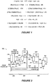
- Figure 1 sets forth some of the interrelated reactions and equilibria believed to be involved in the carbonylation reaction.
- hydrogen iodide (“HI”) may be a component in the underlying chemistry for the production of acetic acid.
- Embodiments of the disclosed process generally include: (a) obtaining HI in an acetic acid production system; and (b) continuously introducing a complexing agent into the system, wherein the complexing agent and HI interact to form a complex.
- a complexing agent into the system, wherein the complexing agent and HI interact to form a complex.
- FIG. 2 is a schematic of an exemplary acetic acid production system 200 implementing the carbonylation reaction.
- the acetic acid system 200 may include a reaction area 202, a light-ends area 204, and a purification area 206.
- the reaction area 202 may include a reactor 210, a flash vessel 220, and associated equipment.
- the reactor 210 is a reactor or vessel in which methanol is carbonylated in the presence of a catalyst to form acetic acid at elevated pressure and temperature.
- the flash vessel 220 is a tank or vessel in which a reaction mixture obtained in the reactor is at least partially depressurized and/or cooled to form a vapor stream and a liquid stream.
- the liquid stream 221 may be a product or composition which has components in the liquid state under the conditions of the processing step in which the stream is formed.
- the vapor stream 226 may be a product or composition which has components in the gaseous state under the conditions of the processing step in which the stream is formed.
- the light-ends area 204 may include a separations column, for example a light-ends column 230, and associated equipment such as decanter 234.
- the light-ends column is a fractioning or distillation column and includes equipment associated with the column, such as heat exchangers, decanters, pumps, compressors, valves, and the like.
- the purification area 206 may include a drying column 240, optionally a heavy-ends column 250, and associated equipment, and so on.
- the heavy-ends column is a fractioning or distillation column and includes any equipment associated with the column, such as heat exchangers, decanters, pumps, compressors, valves, and the like.
- various recycle streams may include streams 221, 238, 239, 248.
- the recycle streams may be products or compositions recovered from a processing step downstream of the flash vessel 220 and which is recycled to the reactor 210, flash vessel 220, or light-ends column 230, and so forth.
- the reactor 210 may be configured to receive a carbon monoxide feed stream 214 and a methanol feed stream 212.
- a reaction mixture may be withdrawn from the reactor in stream 211.
- Other streams may be included as known in the art, for example, a stream that may recycle a bottoms mixture of the reactor 210 back into the reactor 210, or a stream may be included to release a gas from the reactor 210.
- the flash vessel 220 may be configured to receive stream 211 from the reactor 210.
- stream 211 may be separated into a vapor stream 226 and a liquid stream 221.
- the vapor stream 226 may be communicated to the light-ends column 230, and the liquid stream 221 may be communicated to the reactor 210.
- stream 226 may have acetic acid, water, methyl iodide, methyl acetate, HI, mixtures thereof, and the like.
- the light-ends column 230 may be a distillation column and associated equipment such as a decanter 234, pumps, compressors, valves, and other related equipment.
- the light-ends column 230 may be configured to receive stream 226 from the flash vessel 220.
- stream 232 is the overhead product from the light-ends column 230
- stream 231 is bottoms product from the light-ends column 230.
- light-ends column 230 may include a decanter 234, and stream 232 may pass into decanter 234.
- Stream 235 may emit from decanter 234 and recycle back to the light-ends column 230.
- Stream 238 may emit from decanter 234 and may recycle back to the reactor 210 via, for example, stream 212 or be combined with any of the other streams that feed the reactor.
- Stream 239 may recycle a portion of the light phase of decanter 234 back to the reactor 210 via, for example, stream 212.
- Stream 236 may emit from the light-ends column 230.
- Other streams may be included as known in the art, for example, a stream that may recycle a bottoms mixture of the light-ends column 230 back into the light-ends column 230.
- Streams received by or emitted from the light-ends column 230 may pass through a pump, compressor, heat exchanger, and the like as is common in the art.
- the drying column 240 may be a vessel and associated equipment such as heat exchangers, decanters, pumps, compressors, valves, and the like.
- the drying column 240 may be configured to receive stream 236 from the light-ends column 230.
- the drying column 240 may separate components of stream 236 into streams 242 and 241.
- Stream 242 may emit from the drying column 240, recycle back to the drying column via stream 245, and/or recycle back to the reactor 210 through stream 248 (via, for example, stream 212).
- Stream 241 may emit from the drying column 240 and may include de-watered crude acetic acid product.
- Stream 242 may pass through equipment known in the art, for example, a heat exchanger or separation vessel before streams 245 or 248 recycle components of stream 242.
- a stream may recycle a bottoms mixture of the drying column 240 back into the drying column 240.
- Streams received by or emitted from the drying column 240 may pass through a pump, compressor, heat exchanger, separation vessel, and the like as is common in the art.
- the heavy-ends column 250 may be a distillation column and associated equipment such as heat exchangers, decanters, pumps, compressors, valves, and the like.
- the heavy-ends column 250 may be configured to receive stream 241 from the drying column 240.
- the heavy-ends column 250 may separate components from stream 241 into streams 251, 252, and 256.
- Streams 251 and 252 may be sent to additional processing equipment (not shown) for further processing.
- Stream 252 may also be recycled, for example, to light-ends column 240.
- Stream 256 may have acetic acid product.
- a single column may be used in the place of the combination of the light-ends distillation column 230 and the drying column 240.
- the single column may vary in the diameter/height ratio and the number of stages according to the composition of vapor stream from the flash separation and the requisite product quality.
- U.S. Pat. No. 5,416,237 discloses a single column distillation.
- Alternative embodiments for the acetic acid production system 200 may also be found in U.S. Letters Patents 6,552,221 , 7,524,988 , and 8,076,512 .
- the carbonylation reaction in reactor 210 of system 200 may be performed in the presence of a catalyst.
- Catalysts may include, for example, rhodium catalysts and iridium catalysts.
- Suitable rhodium catalysts are taught, for example, by U.S. Letters Patent 5,817,869 .
- the rhodium catalysts may include rhodium metal and rhodium compounds.
- the rhodium compounds may be selected from the group consisting of rhodium salts, rhodium oxides, rhodium acetates, organo-rhodium compounds, coordination compounds of rhodium, the like, and mixtures thereof.
- the rhodium compounds may be selected from the group consisting of Rh2(CO)4I2, Rh2(CO)4Br2, Rh2(CO)4Cl2, Rh(CH3CO2)2, Rh(CH3CO2)3, [H]Rh(CO)2I2, the like, and mixtures thereof.
- the rhodium compounds may be selected from the group consisting of [H]Rh(CO)2I2, Rh(CH3CO2)2, the like, and mixtures thereof.
- Suitable iridium catalysts are taught, for example, by U.S. Letters Patent 5,932,764 .
- the iridium catalysts may include iridium metal and iridium compounds.
- suitable iridium compounds include IrCl3, IrI3, IrBr3, [Ir(CO)2I]2, [Ir(CO)2Cl]2, [Ir(CO)2Br]2, [Ir(CO)4I2]-H+, [Ir(CO)2Br2]-H+, [IR(CO)2I2]-H+, [Ir(CH3)I3(CO)2]-H+, Ir4(CO)12, IrCl3.4H2O, IrBr3.4H2O, Ir3(CO)12, Ir2O3, IrO2, Ir(acac)(CO)2, Ir(acac)3, Ir(OAc)3, [Ir3O(OAc)6(H2O)3][OA
- the iridium compounds may be selected from the group consisting of acetates, oxalates, acetoacetates, the like, and mixtures thereof. In an embodiment, the iridium compounds may be one or more acetates.
- the catalyst may be used with a co-catalyst.
- co-catalysts may include metals and metal compounds selected from the group consisting of osmium, rhenium, ruthenium, cadmium, mercury, zinc, gallium, indium, and tungsten, their compounds, the like, and mixtures thereof.
- co-catalysts may be selected from the group consisting of ruthenium compounds and osmium compounds.
- co-catalysts may be one or more ruthenium compounds.
- the co-catalysts may be one or more acetates.
- the reaction rate depends upon the concentration of the catalyst in the reaction mixture in reactor 210.
- the catalyst concentration may be in a range from 1.0 mmol to 100 mmol catalyst per liter (mmol/ l ) of reaction mixture.
- the catalyst concentration is at least 2.0 mmol/ l , or at least 5.0 mmol/ l , or at least 7.5 mmol/ l .
- the catalyst concentration is at most 75 mmol/ l , or at most 50 mmol/ l , or at least 25 mmol/ l .
- the catalyst concentration is from 2.0 to 75 mmol/ l , or from 5.0 to 50 mmol/ l , or from 7.5 to 25 mmol/ l .
- the carbonylation reaction in reactor 210 of system 200 may be performed in the presence of a catalyst stabilizer.
- Suitable catalyst stabilizers include those known to the industry. In general, there are two types of catalyst stabilizers. The first type of catalyst stabilizer may be a metal iodide salt such as lithium iodide. The second type of catalyst stabilizer may be a non-salt stabilizer. In an embodiment, non-salt stabilizers may be pentavalent Group VA oxides, such as that disclosed in U.S. Letters Patent 5,817 ,. In an embodiment, the catalyst stabilizer may be a phosphine oxide. In an embodiment, the catalyst stabilizer may be a triphenylphosphine oxide ("TPPO").
- TPPO triphenylphosphine oxide
- the amount of pentavalent Group VA oxide, when used, generally is such that a ratio to rhodium is greater than 60:1.
- the ratio of the pentavalent Group 15 oxide to rhodium is from 60:1 to 500:1.
- from 0.1 to 3 M of the pentavalent Group 15 oxide may be in the reaction mixture. More preferably, from 0.15 to 1.5 M, or from 0.25 to 1.2 M, of the pentavalent Group 15 oxide may be in the reaction mixture.
- the reaction may occur in the absence of a stabilizer selected from the group of metal iodide salts and non-metal stabilizers such as pentavalent Group 15 oxides.
- the catalyst stabilizer may consist of an complexing agent which is brought into contact with the reaction mixture stream 211 in the flash vessel 220.
- hydrogen may also be fed into the reactor 210. Addition of hydrogen can enhance the carbonylation efficiency.
- the concentration of hydrogen may be in a range of from 0.1 mol % to 5 mol % of carbon monoxide in the reactor 210. In an embodiment, the concentration of hydrogen may be in a range of from 0.3 mol % to 3 mol % of carbon monoxide in the reactor 210.
- the carbonylation reaction in reactor 210 of system 200 may be performed in the presence of water.
- the concentration of water is from 2 wt % to 14 wt % based on the total weight of the reaction mixture.
- the water concentration is from 2 wt % to 10 wt %.
- the water concentration is from 4 wt % to 8 wt %.
- the carbonylation reaction may be performed in the presence of methyl acetate.
- Methyl acetate may be formed in situ.
- methyl acetate may be added as a starting material to the reaction mixture.
- the concentration of methyl acetate may be from 2 wt % to 20 wt % based on the total weight of the reaction mixture. In an embodiment, the concentration of methyl acetate may be from 2 wt % to 16 wt %. In an embodiment, the concentration of methyl acetate may be from 2 wt % to 8 wt %.
- methyl acetate or a mixture of methyl acetate and methanol from byproduct streams of the methanolysis of polyvinyl acetate or ethylene-vinyl acetate copolymers can be used for the carbonylation reaction.
- the carbonylation reaction may be performed in the presence of methyl iodide.
- Methyl iodide may be a catalyst promoter.
- the concentration of MeI may be from 0.6 wt % to 36 wt % based on the total weight of the reaction mixture. In an embodiment, the concentration of MeI may be from 4 wt % to 24 wt %. In an embodiment, the concentration of MeI may be from 6 wt % to 20 wt %.
- MeI may be generated in the reactor 210 by adding H
- 1 Kg/cm2 98 kPa.
- methanol and carbon monoxide may be fed to the reactor 210 in stream 212 and stream 214, respectively.
- the methanol feed stream to the reactor 210 may come from a syngas-methanol facility or any other source.
- methanol does not react directly with carbon monoxide to form acetic acid. It is converted to MeI by the HI present in the reactor 210 and then reacts with carbon monoxide and water to give acetic acid and regenerate the HI.
- the carbonylation reaction in reactor 210 of system 200 may occur at a temperature within the range of 120° C to 250° C, alternatively, 150° C to 250° C, alternatively, 150° C to 200° C.
- the carbonylation reaction in reactor 210 of system 200 may be performed under a pressure within the range of (200 psig) 14 kg/cm 2 to (2000 psig) 140 kg/cm 2 , alternatively, (200 psia) 14 kg/cm 2 to (1,000 psia) 70 kg/cm 2 , alternatively, (300 psia) 21 kg/cm 2 to (500 psia) 35 kg/cm 2 .
- the reaction mixture may be withdrawn from the reactor 210 through stream 211 and is flashed in flash vessel 220 to form a vapor stream 226 and a liquid stream 221.
- the reaction mixture in stream 211 may include acetic acid, methanol, methyl acetate, methyl iodide, carbon monoxide, carbon dioxide, water, HI, heavy impurities, catalyst, or combinations thereof.
- the flash vessel 220 may generally comprise any configuration for separating vapor and liquid components via a reduction in pressure.
- the flash vessel 220 may comprise a flash tank, nozzle, valve, or combinations thereof.
- the flash vessel 220 may have a pressure below that of the reactor 210. In an embodiment, the flash vessel 220 may have a pressure of from 0.70 kg/cm 2 (10 psig) to 7.03 kg/cm 2 (100 psig). In an embodiment, the flash vessel 220 may have a temperature of from 100 °C to 160 °C.
- the vapor stream 226 may include acetic acid and other volatile components such as methanol, methyl acetate, methyl iodide, carbon monoxide, carbon dioxide, water, entrained HI, complexed HI, and mixtures thereof.
- the liquid stream 221 may include the catalyst, complexed HI, HI, an azeotrope of HI and water, and mixtures thereof.
- the liquid stream 221 may further comprise sufficient amounts of water and acetic acid to carry and stabilize the catalyst, non-volatile catalyst stabilizers, or combinations thereof.
- the liquid stream 221 may recycle to the reactor 210.
- the vapor stream 226 may be communicated to light-ends column 230 for distillation.
- the vapor stream 226 may be distilled in a light-ends column 230 to form an overhead stream 232, a crude acetic acid product stream 236, and a bottom stream 231.
- the light-ends column 230 may have at least 10 theoretical stages or 16 actual stages.
- the light-ends column 230 may have at least 14 theoretical stages.
- the light-ends column 230 may have at least 18 theoretical stages.
- one actual stage may equal approximately 0.6 theoretical stages. Actual stages can be trays or packing.
- the reaction mixture may be fed via stream 226 to the light-ends column 230 at the bottom or the first stage of the column 230.
- Stream 232 may include HAc, water, carbon monoxide, carbon dioxide, methyl iodide, methyl acetate, methanol and acetic acid, and mixtures thereof.
- Stream 231 may have acetic acid, methyl iodide, methyl acetate, HI, water, and mixtures thereof.
- Stream 236 may have acetic acid, HI, water, heavy impurities, and mixtures thereof.
- the light-ends column 230 may be operated at an overhead pressure within the range of (20 psia) 1.4 kg/cm 2 to (40 psia) 2.8 kg/cm 2 , alternatively, the overhead pressure may be within the range of (30 psia) 2 kg/cm 2 to (35 psia) 2.5 kg/cm 2 .
- the overhead temperature may be within the range of 95° C to 135° C, alternatively, the overhead temperature may be within the range of 110° C to 135° C, alternatively, the overhead temperature may be within the range of 125° C to 135° C
- the light-ends column 230 may be operated at a bottom pressure within the range of (25 psia) 1.8 kg/cm 2 to (45 psia) 3.2 kg/cm 2 , alternatively, the bottom pressure may be within the range of (30 psia) 2.1 kg/cm 2 to (40 psia) 2.8 kg/cm 2 .
- the bottom temperature may be within the range of 115° C to 155° C, alternatively, the bottom temperature is within the range of 125° C to 135° C.
- crude acetic acid in stream 236 may be emitted from the light-ends column 240 as a liquid sidedraw.
- Stream 236 may be operated at a pressure within the range of (25 psia) 1.8 kg/cm 2 to (45 psia) 3.2 kg/cm 2 , alternatively, the pressure may be within the range of (30 psia) 2.1 kg/cm 2 to (40 psia) 2.8 kg/cm 2 .
- the temperature of stream 236 may be within the range of 110° C to 140° C, alternatively, the temperature may be within the range of 125° C to 135° C.
- Stream 236 may be taken between the fifth to the eighth actual stage of the light-ends column 230.
- the crude acetic acid in stream 236 may be optionally subjected to further purification, e.g ., drying-distillation, in drying column 240 to remove water and heavy-ends distillation in stream 24.
- Stream 241 may be communicated to heavy-ends column 250 where heavy impurities such as propionic acid may be removed in stream 251 and final acetic acid product may be recovered in stream 256.
- the overhead stream 232 from the light-ends column 230 may be condensed and separated in a decanter 234 to form a light, aqueous phase and a heavy, organic phase.
- a portion or all of the heavy, organic phase may be sent as stream 238 for further processing, as discussed below.
- a portion of stream 238 may be optionally recycled to the reactor 210 via stream 212, for example.
- the portion of stream 238 sent for further processing ( FIG. 2A or FIG. 2B ) and the other portion of the stream 238 recycled to the reactor 210 may each originate as independent streams from the decanter 234 heavy phase.
- the light aqueous phase from the decanter 234 may be recycled to the light-ends column 230 in stream 235 or may be recycled to the reactor 210 in stream 239 via stream 212, for example.
- the heavy, organic phase stream 238 may have HAc, MeI, methyl acetate, hydrocarbons, acetic acid, water, and mixtures thereof.
- stream 238 may be essentially non-aqueous with a water concentration of less than 1 wt%.
- stream 238 may have MeI greater than 50% by weight of the stream.
- the light, aqueous phase in streams 236 and 239 may have water (greater than 50% by weight of the stream), acetic acid, methyl acetate, methyl iodide and acetic acid, and mixtures thereof. Make-up water may be introduced into the decanter 234 via stream 233.
- At least a portion of the heavy, organic phase from the decanter 234 is sent via stream 238 to a distillation column, e.g., hydrocarbons removal column, alkanes column, etc. (depicted exemplary as 270 in Figures 2A and 2B ) to separate MeI from hydrocarbon (e.g ., heavy hydrocarbons, alkanes).
- a distillation column e.g., hydrocarbons removal column, alkanes column, etc.
- the stream 238 is distilled to form a vapor stream having the majority of methyl iodide (over 50% of the methyl iodide from the heavy organic phase 238 from the decanter 234) and a bottoms stream having the majority of acetic acid, methyl acetate, methyl iodide, and the hydrocarbon impurities (over 50% of each component from the heavy organic phase238 from the decanter 234).
- the overhead temperature of the distillation in the alkanes column is generally below 75° C so that there is no significant amount of hydrocarbon impurities coming out with the vapor stream.
- the overhead temperature of the distillation is within the range of 43° C (boiling point of MeI) to 75° C, 43° C to 60° C, or 43° C to 45° C. The closer the overhead temperature of the distillation to the boiling point of MeI, the less the amount of hydrocarbon impurities existing in the vapor stream.
- the vapor stream is recycled to the carbonylation reaction. Lowering the overhead temperature of the heavy phase distillation, although desirably reducing the hydrocarbon impurities in the vapor stream, results undesirably in a higher concentration of MeI in the bottoms stream.
- the bottoms stream is disposed as a waste.
- HAc may also serve undesirably as a precursor to various hydrocarbons which impact decanter 234 heavy density, and as a precursor to higher alkyl iodides which may require expensive adsorption beds for their removal, for example.
- the present techniques provide for an acid catalyzed and ion-exchange resin pathway which contains both kinetically-controlled and thermodynamically-controlled steps to convert HAc.
- the initial kinetically-controlled oligomeric product, paraldehyde has a favorably high boiling point in terms of removal by distillation but unfortunately decomposes when heated above 60 °C.
- the thermodynamically-controlled product, crotonaldehyde (likely formed via an aldol condensation pathway), is stable to temperature and has a sufficiently high boiling point to be removed efficiently by distillation. Conditions, such as acid catalyst and resin concentration, can be tailored to facilitate rapid formation of the thermodynamically-controlled product.
- Acid catalyst or resin concentration and conditions can be tailored to facilitate the thermodynamically-favored crotonaldehyde to be formed rapidly and quantitatively. Crotonaldehyde, though thermally stable, may undergo a further reaction on supported catalysts to form one or more species.
- HAc may be removed from the acetic acid system 200 by providing a stream having HAc from the acetic acid system 200 and contacting the stream (e.g., 238) with an ion-exchange resin.
- the stream (e.g., 238) having HAc may also be treated with liquid catalyst in addition to or in lieu of with ion-exchange resin.
- the ion-exchange resin or liquid catalyst Upon contacting the stream with the ion-exchange resin or liquid catalyst, at least a portion of the HAc in the stream may be converted to an oligomer product, including paraldehyde and crotonaldehyde, for example.
- stream 238 decanter 234 heavy organic phase
- other streams (having HAc) in the acetic acid system 200 may be treated ion-exchange resin (and/or with liquid catalyst) in accordance with the present techniques.
- the stream 238 may be removed from the decanter 234 and at least a portion transferred to a distillation column (e.g ., drying column 240, heavy-ends column 250, or combinations thereof), where an overhead stream having the solution (e.g ., stream 242, stream 252, or combinations thereof) distilled from the heavy phase stream. That overhead stream may be contacted with the ion-exchange resin or liquid catalyst according to the disclosed process, for instance.
- the byproduct HAc in the acetic acid process 200 may be difficult to remove from the process. There are few places in the system where HAc is sufficiently concentrated to efficiently target its removal.
- One location where HAc is sufficiently concentrated is the decanter 234 and in particular, the decanter 234 heavy organic phase (stream 238) where HAc is concentrated to 0.5 wt%, for example. Physical removal of HAc from the decanter 234 and in particular, the decanter 234 heavy organic phase (stream 238) where HAc is concentrated to 0.5 wt%, for example. Physical removal of HAc from
- the present techniques take advantage of HAc's reactivity to convert HAc into high boiling ( i.e., 100 °C or higher) derivatives that are more easily separated from the low boiling MeI by distillation.
- At least a portion of the heavy organic phase (stream 238) is contacted with an ion-exchange resin, e.g., in a resin vessel 260, prior to introduction into the alkanes column 270 (mentioned above).
- an ion-exchange resin e.g., in a resin vessel 260
- 5% to 100 % by weight of the heavy, organic phase exiting the decanter 234 i.e., in stream 238) is contacted with an ion-exchange resin.
- 5% to 50% by weight of the heavy-organic phase exiting the decanter 234 is contacted with an ion-exchange resin.
- Portions of the remainder of the heavy-organic phase 238 exiting the decanter 234 may be recycled (see Figure 2 ) to the reaction zone 202 and/or bypass (not shown) the resin vessel 260 ( Figure 2A ) to the alkanes column 270, for example.
- HAc undergoes rapid acid catalyzed oligomerization to form paraldehyde in an equilibrium reaction which goes to 75% completion, for example, depending on operating conditions in the resin vessel 260.
- Paraldehyde has a boiling point of 124 °C and thus would be a good candidate for separation from MeI by distillation.
- paraldehyde decomposes (back to HAc) upon heating to 60 °C, for instance, and thus while paraldehyde may be the kinetically-favored product of acid catalysis, it is not very stable. Therefore, paraldehyde may not be a suitable candidate in a downstream distillation for separation from MeI.
- paraldehyde generally converts to the thermodynamically-favored crotonaldehyde. This is likely not a direct paraldehyde to crotonaldehyde conversion but rather occurs via paraldehyde reversion to HAc followed by aldol condensation in which two molecules of HAc react together to form crotonaldehyde.
- Crotonaldehyde has a boiling point of 102 °C and thus is another candidate to separate from the low boiling methyl iodide. Unlike paraldehyde, however, crotonaldehyde does not generally decompose to lower boiling compounds upon heating over modest temperatures and times.
- Figure 2B depicts a methanesulfonic acid (MSA) catalyst treatment system 276 in lieu of (or in addition to) employing a resin vessel 260 to treat stream 238.
- MSA methanesulfonic acid
- stream 238 to be treated may include all of the decanter 234 heavy, organic phase or be a slipstream 238 of the decanter 234 heavy, organic phase, with any remainder of the heavy, organic phase recycled to the reaction zone 202 and/or sent directly to the alkanes column 270, for example.
- slipstream 238 is treated with MSA catalyst to convert the acetaldehyde in slipstream 238 to an oligomer such as crotonaldehyde.
- MSA catalyst to treat slipstream may promote undesired side reactions and be equipment-intensive in implementation.
- the MSA catalyst as with the ion-exchange resin, beneficially promotes the thermodynamically-favored crotonaldehyde over the kinetically-favored paraldehyde in the conversion of HAc.
- FIG. 2B depicts the stream (or slipstream) 238 entering the MSA system 276 where liquid MSA catalyst 278 is mixed with stream 238 to convert the HAc in the stream 238 to an oligomer, such as crotonaldehyde.
- a stream 280 exiting the MSA system may resemble the composition of the entering stream 238, except that the HAc is substantially converted to crotonaldehyde, for example.
- stream 280 is sent to the alkanes column 270 where the crotonaldehyde is removed in the bottoms stream 272.
- the overhead stream having primarily methyl iodide may be recycled to the reaction area 202, such as to the flash vessel 220 (see Figure 2 ).
- the mixture of stream 238 and MSA 278 is flashed (i.e., depressured and/or heated) in the MSA system 276 after sufficient contact time to produce stream 280 (vapor) from the flashed mixture.
- the boiling point of MSA is generally significantly higher than the components in stream 238 and the yielded crotonaldehyde, such that the flash operation may not incorporate the liquid MSA in stream 280.
- unit operations other than a flash operation may be employed in the MSA system 278.
- a decanter-type operation may be employed to recover the liquid MSA catalyst and forward a resulting stream 280 with the crotonaldehyde to the alkanes column 270.
- a stripper or counter-current flow device may be used to contact the liquid MSA catalyst with the entering stream 238 and to produce stream 280.
- streams other than stream 238 in the acetic acid system 200 having HAc may be processed in a MSA catalyst system.
- contacting the solution with the ion-exchange resin may occur at room temperature, ambient temperature, or a temperature below the boiling point of HAc, and so on. In an embodiment, contacting the solution with the ion-exchange resin may occur for at least 30 minutes.
- the mass ratio of aldehyde to ion-exchange resin may be in a range of 0.1 to 2.0, for example.
- a stream 238 is discharged from the heavy organic phase of the decanter 234. This heavy organic phase includes a solution of HAc and methyl iodide.
- At least a portion of the heavy organic phase (stream 238) may pass to the resin vessel 260, where the solution may be contacted with the ion-exchange resin according to the disclosed process.
- the decanter 234 heavy organic phase (stream 238) where acetaldehyde is present at 0.5 wt% for example, other streams having HAc (and MeI) in the acetic acid system 200 may be treated in accordance with the present techniques.
- the ion-exchange resins may include strongly acidic ion-exchange resins, for example, such as AMBERLYSTTM 15Dry.
- strongly acidic ion-exchange resins for example, such as AMBERLYSTTM 15Dry.
- This is a bead form, strongly acidic ion exchange resin developed particularly for heterogeneous acid catalysis of a wide variety of organic reaction. It is available from The Dow Chemical Company and may be purchased therefrom over the World Wide Web of the Internet at www.dow.com. Additional information regarding this product may be found at http://www.dow.com/products/product/amberlyst-15dry/ .
- AMBERLYSTTM 15Dry may be manufactured as opaque beads and may have a macroreticular pore structure with hydrogen ion sites located throughout each bead. The surface area may be 53 m 2 /g, the average pore diameter may be 300 Angstroms, and the total pore volume may be 0.40 cc/g. AMBERLYSTTM 15Dry may be utilized in essentially non-aqueous systems (e.g., less than 1 wt% water). Therefore, the solution may be essentially or substantially nonaqueous with use of AMBERLYSTTM 15Dry.
- HAc by virtue of its polar carbonyl group is very reactive. Oligomerization in a MeI/HAc solution to paraldehyde may only slowly take place without any acid catalyst being present. In contrast, in the presence of a small amount of acid catalyst resin such as Amberlyst 15, this oligomerization of HAc to paraldehyde is essentially instantaneous, as constructed in Figure 3 (and with liquid unsupported catalyst MSA in Figure 5 ). Notably, generally regardless of the nature of the acid resin catalyst or the catalyst concentration, oligomerization only goes to 75% completion in certain embodiments, indicating an equilibrium reaction.
- acid catalyst resin such as Amberlyst 15
- Figure 3 shows overlaid in-situ infrared spectra for a solution of 4.8 wt% HAc and MeI contacted with an ion-exchange resin (AMBERLYSTTM 15Dry), taken with an infrared spectrometer.
- the mass ratio of HAc to ion-exchange resin is 1:2.
- Spectra are shown for time values of zero minutes and 1 minute. While that paraledyde appearance in the solution is rapid, there is a very small amount of contact time experienced for the initial paraldehyde presence that rapidly arises. For clarity, it should be noted that the zero minutes in Figure 3 is defined after this very small amount of time and at the beginning of the paraldehyde decay.
- the HAc undergoes aldol condensation to form crotonaldehyde, as indicated in Figure 4 .
- the infrared spectra in Figure 4 shows the acid catalyzed conversion of initially formed paraldehyde to crotonaldehyde over a 45 minute period at room temperature with the initial solution of HAc and MeI contacted with the ion-exchange resin.
- Figure 4 shows tat with the initial, rapid acid resin catalyzed conversion of HAc to paraldehyde at room temperature, when the solution is monitored over time, the initial, rapidly formed paraldehyde essentially disappears with simultaneous formation of the aldol condensation produced, crotonaldehyde.
- Overlaid spectra showing this behavior are contained in Figure 4 .
- Figure 4 shows an overlaid in-situ infrared spectra for a solution of HAc and MeI contacted with an ion-exchange resin (AMBERLYSTTM 15Dry), taken with an infrared spectrometer.
- MSA mineral methanesulfonic acid
- Figure 5 which defines time zero as the beginning of rapidly-formed paraldehyde decay.
- Figure 7 the rate of crotonaldehyde formation (paraldehyde decay) is dependent on acid concentration (see Figure 7 ).
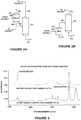
- Figure 5 shows a graph of infrared absorbance versus time for a solution of HAc and MeI contacted with MSA.
- the graph includes infrared absorbance plots for crotonaldehyde, paraldehyde, and HAc.
- the mass ratio of HAc to MSA is 1:3.
- the components were contacted at room temperature.
- the infrared absorbance of paraldehyde an initial large presence is realized followed by a sharp drop concluding with a gradual reduction to a negligible amount.
- the infrared absorbance of HAc gradually decreases, and the infrared absorbance of crotonaldehyde gradually increases to substantially leveling off with a slight decrease.
- time zero on the plot in Figure 5 refers to the point at which 75% of staring HAc has already substantially instantly converted to paraldehyde.
- a slipstream 238 of the decanter 234 heavy phase may be passed to a distillation column 270 (e.g., called the alkanes tower) to remove byproduct hydrocarbons in a high-boiling bottoms stream 272.
- the overhead stream 274 (low boilers, primarily MeI and HAc) of the alkanes tower 270 is recycled to the process ( e.g., to the reaction area 202) while the bottoms stream 272 (high boilers) is disposed of as waste in certain examples.
- the disclosed process may deliberately promote formation of oligomer product (e.g ., crotonaldehyde) in the acetic acid system 200, such as in the slipstream 238 sent to the alkanes column 270.
- oligomer product e.g ., crotonaldehyde
- a portion or all of stream 238 may be sent through a slurry bed of ion-exchange resin (e.g., Amberlyst 15 resin in vessel 260) to convert HAc to crotonaldehyde.
- a portion of stream 238 may optionally bypass (not shown) the resin vessel 260 and be fed directly to the alkanes column 270.
- Two basic exemplary scenarios include a first scenario (or scenario 1) and a second scenario (or scenario 2).
- scenario 1 the crotonaldehyde formed remains in solution and is passed on to the alkanes column 270 for removal via the bottoms waste stream 272.
- scenario 2 the crotonaldehyde is fully adsorbed onto the resin in vessel 260, and later removed from the system 200 via regeneration of the resin in vessel 260.
- first and second scenarios may exist between the first and second scenarios, where only some of the crotonaldehyde in adsorbed onto the resin in vessel 260, for instance.
- the crotonaldehyde formed remains in solution in the resin vessel 260 and is passed on to the alkanes column 270 in the treated stream 238 labeled as stream 262.
- This treated stream 238, labeled as stream 262 discharges from the resin vessel 260 and is sent onwards to the alkanes tower 270 ( Figure 2A ) where crotonaldehyde will be removed in the bottoms waste stream 272 along with the byproduct hydrocarbons (alkanes including heavy alkanes).
- bottoms stream 272 may be further processed instead of disposed as waste.
- the crotonaldehyde formed e.g., in resin vessel 260
- the ion-exchange resin e.g., in resin vessel 260
- the treated stream 238, labeled at stream 262 is substantially free of HAc (converted to crotonaldehyde) and free of the formed crotonaldehyde (adsorbed onto the resin).
- the stream 262 may be sent to the alkanes column 270 and/or recycled to the reaction zone 202, for example.
- stream 262 in scenario 2 may also be recycled to the decanter 234, light-ends column 230, reactor 210, other point in system 200, or combinations thereof.
- the stream 262 generally includes MeI which is desirable to recover and reuse in the system 200.
- the resin once saturated or prior to saturation can be regenerated offline to recover via stream 264 the crotonaldehyde adsorbed on the resin.
- the crotonaldehyde desorbed from the resin may discharge in stream 264 as different species.
- this heavy phase 262 is depleted in both HAc and crotonaldehyde in scenario 2, and can be recycled directly to the process ( e.g., to the reactor 210 via stream 212, as shown in Figure 2 ), and/or sent to alkanes tower 270 for removal of byproduct hydrocarbons, as shown in Figure 2A .
- the crotonaldehyde formed in the presence of Amberlyst 15 acid resin may be substantially fully adsorbed.
- less than full adsorption onto the resin may be realized, depending on the resin concentration, temperature and contact time with resin, and so on.
- Figures 6 and 7 indicate the degree of adsorption of the crotonaldehyde on the resin as a function of temperature and resin concentration, respectively.
- Figure 6 is a graph of % HAc as crotonaldehyde versus time for a solution of MeI and HAc contacted with ion-exchange resin at three different temperatures. Three plots at different temperatures are depicted. The plot at 0 °C and the plot at 21 °C both show the presence of crotonaldehyde (from the HAc) in solution as increasing. In contrast, the plot at 33 °C shows the crotonaldehyde (from HAc) in solution increasing initially but beginning to decrease at 25 minutes, indicating that crotonaldehyde is leaving the solution and being adsorbed onto the resin.
- Figure 7 shows that the % crotonaldehyde remaining in solution is less at greater time and less at greater resin concentrations, thus indicating that more crotonaldehyde is adsorbed onto the resin (as opposed to remaining in solution) over time and at greater resin concentration ( i.e., greater amounts of resin).
- crotonaldehyde disappears with the rate of disappearance directly dependent on acid concentration. No other new infrared peak was observed, suggesting that crotonaldehyde is either adsorbing directly on the resin or is decomposing to some other species that is adsorbing on the resin.
- an operating temperature, for example, of resin vessel 260 may be specified to drive that the crotonaldehyde remain in solution, or conversely, that the crotonaldehyde adsorb onto the resin.
- an exemplary temperature range of 0 to 30 °C may be specified, for example.
- temperatures in excess of 30 °C may be specified, for example. The upper temperature being limited by pressure ratings of vessels used to contain the resin slurry or bed, for instance.
- the ion-exchange resin may be regenerated to remove the components adsorbed onto the resin.
- the resin may be heated and the adsorbed components (e.g ., crotonaldehyde) desorbed and discharged from the resin vessel 260 via stream 264.
- Stream 264 may be recovered or disposed as waste.
- the disclosed process may be performed in a continuous format.
- two resin beds or two resin vessels e.g ., two resin vessels 260
- the resin vessel 260 may be in continuous or batch operation and may include a tank of dimension and material as known in the industry for production of acetic acid.
- the oligomer product may be removed from the solution, for example, by adsorbing at least a portion of the oligomer product onto the ion-exchange resin to yield an adsorbent resin product, and/or by forwarding the solution (stream 262) having the non-adsorbed oligomer product (to be removed) to further processing such as to alkanes column 270 where the oligomer product is removed in the bottoms stream 272.
- the solution should be partially or substantially depleted of HAc and crotonaldehyde, and the remaining MeI may be recovered from the solution, for example in sending stream 262 to the alkanes column 270 with MeI exiting in the overhead stream 274 of the alkanes column 270.
- the stream 262 may also be recycled to in the system 200, especially if substantially depleted of HAc and crotonaldehyde.
- the stream 262 may be sent to the alkanes column 270, the MeI recovered in the overhead stream 274 and the crotonaldehyde discharged in the bottoms stream 272 ( e.g., as waste).
- the adsorbent product (i.e., resin having adsorbed oligomer) in resin vessel 260 may then be separated into (1) oligomer or HAc and (2) a regenerated ion-exchange resin.
- the adsorbent product may be heated to a temperature above 21 °C in order to separate oligomer and/or HAc from the resin to regenerate the ion-exchange resin (e.g., by desorption of oligomer and/or HAc gas in resin vessel 260). Desorbed oligomer and/or desorbed HAc may be recovered in stream 264.
- the adsorbent product (resin) may be heated to a temperature of 80 °C or more in order to separate HAc to regenerate the ion-exchange resin.
- the present techniques may involve a method for removing acetaldehyde from an acetic acid system, including providing a solution having at least methyl iodide and acetaldehyde from the acetic acid system, and contacting the solution with an ion-exchange resin (e.g., a strongly acidic ion-exchange resin) to convert at least a portion of the acetaldehyde to yield an oligomer including crotonaldehyde and which may be removed from the solution.
- an ion-exchange resin e.g., a strongly acidic ion-exchange resin
- Removing the oligomer or crotonaldehyde may include distilling the solution and discharging the oligomer in a bottom stream, and/or adsorbing at least a portion of the oligomer onto the ion-exchange resin, and further regenerating the ion-exchange resin to remove the oligomer from the acetic acid system.
- the method may also include recovering methyl iodide from the solution, and recycling the recovered methyl iodide to within the acetic acid system.
- the solution is contacted with the ion-exchange resin at room temperature for at least 30 minutes, and wherein the mass ratio of HAc to ion-exchange resin is in a range of 0.5 to 2.0.
- the method may account for the acetic acid system having a decanter, the method including removing a heavy phase stream having the solution from the decanter, and passing the heavy phase stream to a resin vessel having the ion-exchange resin, and wherein contacting the solution is performed in the resin vessel.
- Regenerating the resin may include heating the ion-exchange resin to a temperature above 21 °C, for example, and separating the oligomer from the ion-exchange resin.
- regenerating may include heating the ion-exchange resin having the adsorbed oligomer to a temperature of 80 °C or greater, and separating the oligomer from the ion-exchange resin.
- the present techniques may also provide for a method of operating an acetic acid production system, including flashing a reaction mixture discharged from an acetic acid production reactor into a vapor stream and a liquid stream, the vapor stream comprising acetic acid, water, methanol, methyl acetate, methyl iodide, and acetaldehyde.
- the method includes distilling the vapor stream into: (1) a product side stream comprising acetic acid and water; (2) a bottoms stream; and (3) an overhead stream comprising methyl iodide, water, methyl acetate, acetic acid, and acetaldehyde.
- This method further includes condensing the overhead stream into: (1) a light, aqueous phase comprising water, acetic acid, and methyl acetate; and (2) a heavy, organic phase comprising methyl iodide, acetic acid, water, and the acetaldehyde.
- the method includes converting the acetaldehyde in at least a portion of the heavy, organic phase to an oligomer. Such a conversion may occur by contacting the at least a portion of the heavy, organic phase with an ion-exchange resin and/or with a liquid MSA catalyst.
- This method of operating an acetic acid production system may include may include adsorbing the oligomer (e.g ., crotonaldehyde) onto the ion-exchange resin, and regenerating the ion-exchange resin to separate the crotonaldehyde from the ion-exchange resin.
- the method may include distilling the at least a portion of the heavy, organic phase after contact with the ion-exchange resin into a vapor stream having methyl iodide and a bottoms stream having the oligomer ( e.g ., crotonaldehyde).
- the present techniques provide for a method of producing acetic acid, including reacting methanol and carbon monoxide in the presence of a carbonylation catalyst to produce a crude stream having the produced acetic acid.
- This method includes purifying the crude stream to produce a product stream having the acetic acid, wherein the purifying generates a methyl iodide stream having at least methyl iodide acetaldehyde.
- the method involves contacting the methyl iodide stream with an ion-exchange resin to convert the acetaldehyde to crotonaldehyde to reduce an amount of acetaldehyde in the production of acetic acid.
- an acetic acid production system including: a reactor to react methanol and carbon monoxide in the presence of a carbonylation catalyst to form acetic acid; a flash vessel that receives a reaction mixture comprising the acetic acid from the reactor; a distillation column that receives a vapor stream from the flash vessel; a decanter that receives a condensed overhead stream from the distillation column; and a resin vessel that receives a heavy, organic phase having at least methyl iodide and acetaldehyde from the decanter, the resin vessel having an ion-exchange resin to convert the acetaldehyde to an oligomer.
- a majority by weight of the heavy, organic phase is methyl iodide
- the oligomer includes crotonaldehyde.
- Examples 1-7 infrared spectra were collected on a Nicolet 6700 FTIR spectrometer obtained from Thermo Scientific. The spectrometer was equipped with a Smart Miracle accessory also obtained from Thermo Scientific. The accessory contained a 3 bounce, zinc selenide ATR crystal. Those skilled in the art of infrared spectroscopy will realize that use of such an accessory will allow infrared absorbance peaks of HAc, crotonaldehyde and paraldehyde to be monitored and quantified. Examples 1-7 address static slurries or mixtures. Examples 8 and 9 address a flow-through bed mode.
- Examples 1-3 are associated with Figure 8 which is a graph of % paraldehyde remaining versus time. Three plots at different MSA concentrations are given corresponding respectively to Examples 1-3.
- Examples 4-6 are associated with Figure 7 mentioned above, which is a graph of % crotonaldehyde remaining in solution versus time. Three plots at different Amberlyst 15 resin concentrations corresponding respectively to Examples 4-6 are depicted.
- Example 7 is associated with Figure 9 which is a graph of % crotonaldehyde unreacted versus time. A single plot depicts am essentially flat curve at 100% crotonaldehyde unreacted over time.
- Example 1 was repeated with the exception that 0.054 grams of MSA was used. After 2 hours, 75 % conversion of paraldehyde to crotonaldehyde had taken place.
- Example 1 was repeated with the exception that 0.37 grams of MSA was used. After 90 minutes, 95% conversion of paraldehyde to crotonaldehyde had taken place.
- Example 4 was repeated with the exception that 0.50 grams of Amberlyst 15 was used. After 80 minutes, 75% of the crotonaldehyde had been adsorbed on the resin.
- Example 4 was repeated with the exception that 1.0 grams of Amberlyst 15 was used. After 80 minutes, 90% of the crotonaldehyde had been adsorbed on the resin.
- Example 4 was repeated with the exception that methanesulfonic acid was used as the acid catalyst. 0.07 grams of methanesulfonic acid, heated to 33C, was added to 4.0 grams of the solution as described in Example 1. At 110 minutes, 0% of the crotonaldehyde had disappeared from solution.
- a solution composed of 9.5 wt% HAc dissolved in methyl iodide was passed in continuous downward flow mode at room temperature through a 10 gram bed of Amberlyst 15 maintained between layers of glass wool in a glass column with a length to diameter ratio of 1.6. An approximate flow rate of 4 bed volumes per hour (BV/hr) was maintained for 35 minutes.
- feedstock was passed through a water condenser placed at the top of the column.
- such aliquots were collected into vials contained within an ice bath.
Landscapes
- Chemical & Material Sciences (AREA)
- Organic Chemistry (AREA)
- Engineering & Computer Science (AREA)
- Oil, Petroleum & Natural Gas (AREA)
- Crystallography & Structural Chemistry (AREA)
- Organic Low-Molecular-Weight Compounds And Preparation Thereof (AREA)
- Chemical Kinetics & Catalysis (AREA)
Applications Claiming Priority (2)
| Application Number | Priority Date | Filing Date | Title |
|---|---|---|---|
| US13/664,549 US8969613B2 (en) | 2012-10-31 | 2012-10-31 | Removal of aldehydes in acetic acid production |
| PCT/US2013/067266 WO2014070739A1 (en) | 2012-10-31 | 2013-10-29 | Removal of aldehydes in acetic acid production |
Publications (3)
| Publication Number | Publication Date |
|---|---|
| EP2914570A1 EP2914570A1 (en) | 2015-09-09 |
| EP2914570A4 EP2914570A4 (en) | 2016-06-29 |
| EP2914570B1 true EP2914570B1 (en) | 2021-06-09 |
Family
ID=50547886
Family Applications (1)
| Application Number | Title | Priority Date | Filing Date |
|---|---|---|---|
| EP13850770.2A Active EP2914570B1 (en) | 2012-10-31 | 2013-10-29 | Removal of aldehydes in acetic acid production |
Country Status (9)
| Country | Link |
|---|---|
| US (1) | US8969613B2 (pt) |
| EP (1) | EP2914570B1 (pt) |
| KR (2) | KR20160052814A (pt) |
| CN (1) | CN104736510B (pt) |
| BR (1) | BR112015009005B1 (pt) |
| CA (1) | CA2888066C (pt) |
| RU (1) | RU2595035C1 (pt) |
| SG (1) | SG11201502686SA (pt) |
| WO (1) | WO2014070739A1 (pt) |
Families Citing this family (11)
| Publication number | Priority date | Publication date | Assignee | Title |
|---|---|---|---|---|
| US8968613B2 (en) | 2012-07-12 | 2015-03-03 | 3M Innovative Properties Company | Method of making an earplug |
| EP3131873A1 (en) * | 2014-06-20 | 2017-02-22 | BP Chemicals Limited | Improved catalytic performance in processes for preparing acetic acid |
| US9873655B2 (en) | 2015-12-03 | 2018-01-23 | Lyondellbasell Acetyls, Llc | Selective removal of impurities in acetic acid production processes |
| US9908833B2 (en) | 2015-12-03 | 2018-03-06 | Lyondellbasell Acetyls, Llc | Removal of aldehydes in acetic acid production processes |
| ES2967529T3 (es) | 2016-07-12 | 2024-04-30 | Sabic Global Technologies Bv | Sistemas y métodos de purificación de acetona |
| CN111918857A (zh) * | 2018-03-23 | 2020-11-10 | 利安德巴塞尔乙酰有限责任公司 | 冰乙酸(gaa)纯化的改进方法 |
| WO2019183549A1 (en) | 2018-03-23 | 2019-09-26 | Lyondellbasell Acetyls, Llc | Removal of permanganate reducing compounds from intermediate gaa process streams |
| US20220185760A1 (en) * | 2019-04-01 | 2022-06-16 | Celanese International Corporation | Aldehyde removal process for methanol carbonylation |
| US20230234908A1 (en) | 2022-01-11 | 2023-07-27 | Lyondellbasell Acetyls, Llc | Removal of aldehydes in acetic acid production |
| US20230265036A1 (en) | 2022-02-18 | 2023-08-24 | Lyondellbasell Acetyls, Llc | Removal of aldehydes in acetic acid production |
| CN117942722A (zh) * | 2024-03-27 | 2024-04-30 | 河北建滔能源发展有限公司 | 一种用于去除醋酸中醛类杂质的脱醛塔 |
Citations (1)
| Publication number | Priority date | Publication date | Assignee | Title |
|---|---|---|---|---|
| US5620567A (en) * | 1993-08-12 | 1997-04-15 | Hoechst Aktiengesellschaft | Process for the removal of aldehydes and acetals from industrially prepared acetic acid |
Family Cites Families (18)
| Publication number | Priority date | Publication date | Assignee | Title |
|---|---|---|---|---|
| US5817A (en) | 1848-10-03 | Improvement in machinery for cleaning tobacco-leaves | ||
| US5175363A (en) * | 1991-01-28 | 1992-12-29 | Eastman Kodak Company | Method for purification of carboxylic acids and anhydrides |
| GB9211671D0 (en) | 1992-06-02 | 1992-07-15 | Bp Chem Int Ltd | Process |
| US5625095A (en) | 1994-06-15 | 1997-04-29 | Daicel Chemical Industries, Ltd. | Process for producing high purity acetic acid |
| US5723660A (en) * | 1995-04-24 | 1998-03-03 | Daicel Chemical Industries, Ltd. | Process for producing acetic acid |
| US5817869A (en) | 1995-10-03 | 1998-10-06 | Quantum Chemical Corporation | Use of pentavalent Group VA oxides in acetic acid processing |
| GB9625335D0 (en) | 1996-12-05 | 1997-01-22 | Bp Chem Int Ltd | Process |
| WO1999050218A1 (en) * | 1998-03-31 | 1999-10-07 | Haldor Topsøe A/S | Process for production of acetic acid |
| US6552221B1 (en) | 1998-12-18 | 2003-04-22 | Millenium Petrochemicals, Inc. | Process control for acetic acid manufacture |
| US7223883B2 (en) | 2004-03-02 | 2007-05-29 | Celanese International Corporation | Removal of permanganate reducing compounds from methanol carbonylation process stream |
| JP4526381B2 (ja) * | 2004-12-27 | 2010-08-18 | ダイセル化学工業株式会社 | 酢酸の製造方法 |
| US7524988B2 (en) * | 2006-08-01 | 2009-04-28 | Lyondell Chemical Technology, L.P. | Preparation of acetic acid |
| US7485749B2 (en) * | 2006-08-22 | 2009-02-03 | Lyondell Chemical Technology, L.P. | Preparation of acetic acid |
| US20090209786A1 (en) | 2007-05-21 | 2009-08-20 | Scates Mark O | Control of impurities in product glacial acetic acid of rhodium-catalyzed methanol carbonylation |
| US7345197B1 (en) | 2007-06-05 | 2008-03-18 | Lyondell Chemical Technology, L.P. | Preparation of acetic acid |
| US7390919B1 (en) | 2007-10-01 | 2008-06-24 | Lyondell Chemical Technology, L.P. | Methyl acetate purification and carbonylation |
| US8076512B2 (en) | 2009-08-27 | 2011-12-13 | Equistar Chemicals, L.P. | Preparation of acetic acid |
| US8519181B2 (en) * | 2010-04-07 | 2013-08-27 | Lyondell Chemical Technology, L.P. | Preparation of acetic acid |
-
2012
- 2012-10-31 US US13/664,549 patent/US8969613B2/en active Active
-
2013
- 2013-10-29 EP EP13850770.2A patent/EP2914570B1/en active Active
- 2013-10-29 CN CN201380054656.5A patent/CN104736510B/zh active Active
- 2013-10-29 WO PCT/US2013/067266 patent/WO2014070739A1/en active Application Filing
- 2013-10-29 CA CA2888066A patent/CA2888066C/en active Active
- 2013-10-29 SG SG11201502686SA patent/SG11201502686SA/en unknown
- 2013-10-29 KR KR1020167011704A patent/KR20160052814A/ko not_active Application Discontinuation
- 2013-10-29 RU RU2015118021/04A patent/RU2595035C1/ru active
- 2013-10-29 KR KR1020157012676A patent/KR101675705B1/ko active IP Right Grant
- 2013-10-29 BR BR112015009005-2A patent/BR112015009005B1/pt active IP Right Grant
Patent Citations (1)
| Publication number | Priority date | Publication date | Assignee | Title |
|---|---|---|---|---|
| US5620567A (en) * | 1993-08-12 | 1997-04-15 | Hoechst Aktiengesellschaft | Process for the removal of aldehydes and acetals from industrially prepared acetic acid |
Also Published As
| Publication number | Publication date |
|---|---|
| KR20160052814A (ko) | 2016-05-12 |
| WO2014070739A1 (en) | 2014-05-08 |
| US8969613B2 (en) | 2015-03-03 |
| BR112015009005B1 (pt) | 2021-03-23 |
| EP2914570A1 (en) | 2015-09-09 |
| RU2595035C1 (ru) | 2016-08-20 |
| BR112015009005A2 (pt) | 2017-07-04 |
| CN104736510A (zh) | 2015-06-24 |
| US20140121404A1 (en) | 2014-05-01 |
| CA2888066A1 (en) | 2014-05-08 |
| KR20150067372A (ko) | 2015-06-17 |
| SG11201502686SA (en) | 2015-05-28 |
| KR101675705B1 (ko) | 2016-11-11 |
| CN104736510B (zh) | 2016-06-01 |
| CA2888066C (en) | 2016-09-27 |
| EP2914570A4 (en) | 2016-06-29 |
Similar Documents
| Publication | Publication Date | Title |
|---|---|---|
| EP2914570B1 (en) | Removal of aldehydes in acetic acid production | |
| JP6404125B2 (ja) | カルボン酸の製造方法 | |
| US11014867B2 (en) | Processes for producing an acetic acid product having low butyl acetate content | |
| KR101851035B1 (ko) | 아세트산의 제조 방법 | |
| JP6047094B2 (ja) | 高転化率での酢酸の製造 | |
| EP3201165B1 (en) | Process for producing acetic acid | |
| JP6022001B1 (ja) | 酢酸の製造方法 | |
| EP3374341B1 (en) | Processes for purifying acetic acid and hydrating anhydride | |
| EP3218347A1 (en) | Processes for producing acetic acid from a reaction medium having low ethyl iodide content | |
| EP3218345B1 (en) | Process for producing acetic acid by introducing a lithium compound | |
| EP3374342B1 (en) | Processes for producing acetic acid | |
| US20230234908A1 (en) | Removal of aldehydes in acetic acid production | |
| US20230257335A1 (en) | Removal of aldehydes in acetic acid production | |
| WO2023158791A1 (en) | Removal of aldehydes in acetic acid production | |
| WO2016076970A1 (en) | Processes for producing acetic acid from a reaction medium having low ethyl iodide content |
Legal Events
| Date | Code | Title | Description |
|---|---|---|---|
| PUAI | Public reference made under article 153(3) epc to a published international application that has entered the european phase |
Free format text: ORIGINAL CODE: 0009012 |
|
| 17P | Request for examination filed |
Effective date: 20150506 |
|
| AK | Designated contracting states |
Kind code of ref document: A1 Designated state(s): AL AT BE BG CH CY CZ DE DK EE ES FI FR GB GR HR HU IE IS IT LI LT LU LV MC MK MT NL NO PL PT RO RS SE SI SK SM TR |
|
| AX | Request for extension of the european patent |
Extension state: BA ME |
|
| DAX | Request for extension of the european patent (deleted) | ||
| RA4 | Supplementary search report drawn up and despatched (corrected) |
Effective date: 20160601 |
|
| RIC1 | Information provided on ipc code assigned before grant |
Ipc: B01J 19/24 20060101ALI20160525BHEP Ipc: C07C 57/04 20060101ALI20160525BHEP Ipc: C07C 51/42 20060101AFI20160525BHEP |
|
| STAA | Information on the status of an ep patent application or granted ep patent |
Free format text: STATUS: EXAMINATION IS IN PROGRESS |
|
| 17Q | First examination report despatched |
Effective date: 20190301 |
|
| GRAP | Despatch of communication of intention to grant a patent |
Free format text: ORIGINAL CODE: EPIDOSNIGR1 |
|
| STAA | Information on the status of an ep patent application or granted ep patent |
Free format text: STATUS: GRANT OF PATENT IS INTENDED |
|
| INTG | Intention to grant announced |
Effective date: 20210114 |
|
| GRAS | Grant fee paid |
Free format text: ORIGINAL CODE: EPIDOSNIGR3 |
|
| GRAA | (expected) grant |
Free format text: ORIGINAL CODE: 0009210 |
|
| STAA | Information on the status of an ep patent application or granted ep patent |
Free format text: STATUS: THE PATENT HAS BEEN GRANTED |
|
| AK | Designated contracting states |
Kind code of ref document: B1 Designated state(s): AL AT BE BG CH CY CZ DE DK EE ES FI FR GB GR HR HU IE IS IT LI LT LU LV MC MK MT NL NO PL PT RO RS SE SI SK SM TR |
|
| REG | Reference to a national code |
Ref country code: GB Ref legal event code: FG4D |
|
| REG | Reference to a national code |
Ref country code: CH Ref legal event code: EP Ref country code: AT Ref legal event code: REF Ref document number: 1400388 Country of ref document: AT Kind code of ref document: T Effective date: 20210615 |
|
| REG | Reference to a national code |
Ref country code: DE Ref legal event code: R096 Ref document number: 602013077884 Country of ref document: DE |
|
| REG | Reference to a national code |
Ref country code: IE Ref legal event code: FG4D |
|
| REG | Reference to a national code |
Ref country code: LT Ref legal event code: MG9D |
|
| PG25 | Lapsed in a contracting state [announced via postgrant information from national office to epo] |
Ref country code: HR Free format text: LAPSE BECAUSE OF FAILURE TO SUBMIT A TRANSLATION OF THE DESCRIPTION OR TO PAY THE FEE WITHIN THE PRESCRIBED TIME-LIMIT Effective date: 20210609 Ref country code: BG Free format text: LAPSE BECAUSE OF FAILURE TO SUBMIT A TRANSLATION OF THE DESCRIPTION OR TO PAY THE FEE WITHIN THE PRESCRIBED TIME-LIMIT Effective date: 20210909 Ref country code: LT Free format text: LAPSE BECAUSE OF FAILURE TO SUBMIT A TRANSLATION OF THE DESCRIPTION OR TO PAY THE FEE WITHIN THE PRESCRIBED TIME-LIMIT Effective date: 20210609 Ref country code: FI Free format text: LAPSE BECAUSE OF FAILURE TO SUBMIT A TRANSLATION OF THE DESCRIPTION OR TO PAY THE FEE WITHIN THE PRESCRIBED TIME-LIMIT Effective date: 20210609 |
|
| REG | Reference to a national code |
Ref country code: AT Ref legal event code: MK05 Ref document number: 1400388 Country of ref document: AT Kind code of ref document: T Effective date: 20210609 |
|
| REG | Reference to a national code |
Ref country code: NL Ref legal event code: MP Effective date: 20210609 |
|
| PG25 | Lapsed in a contracting state [announced via postgrant information from national office to epo] |
Ref country code: LV Free format text: LAPSE BECAUSE OF FAILURE TO SUBMIT A TRANSLATION OF THE DESCRIPTION OR TO PAY THE FEE WITHIN THE PRESCRIBED TIME-LIMIT Effective date: 20210609 Ref country code: GR Free format text: LAPSE BECAUSE OF FAILURE TO SUBMIT A TRANSLATION OF THE DESCRIPTION OR TO PAY THE FEE WITHIN THE PRESCRIBED TIME-LIMIT Effective date: 20210910 Ref country code: SE Free format text: LAPSE BECAUSE OF FAILURE TO SUBMIT A TRANSLATION OF THE DESCRIPTION OR TO PAY THE FEE WITHIN THE PRESCRIBED TIME-LIMIT Effective date: 20210609 Ref country code: RS Free format text: LAPSE BECAUSE OF FAILURE TO SUBMIT A TRANSLATION OF THE DESCRIPTION OR TO PAY THE FEE WITHIN THE PRESCRIBED TIME-LIMIT Effective date: 20210609 Ref country code: NO Free format text: LAPSE BECAUSE OF FAILURE TO SUBMIT A TRANSLATION OF THE DESCRIPTION OR TO PAY THE FEE WITHIN THE PRESCRIBED TIME-LIMIT Effective date: 20210909 |
|
| PG25 | Lapsed in a contracting state [announced via postgrant information from national office to epo] |
Ref country code: SK Free format text: LAPSE BECAUSE OF FAILURE TO SUBMIT A TRANSLATION OF THE DESCRIPTION OR TO PAY THE FEE WITHIN THE PRESCRIBED TIME-LIMIT Effective date: 20210609 Ref country code: SM Free format text: LAPSE BECAUSE OF FAILURE TO SUBMIT A TRANSLATION OF THE DESCRIPTION OR TO PAY THE FEE WITHIN THE PRESCRIBED TIME-LIMIT Effective date: 20210609 Ref country code: CZ Free format text: LAPSE BECAUSE OF FAILURE TO SUBMIT A TRANSLATION OF THE DESCRIPTION OR TO PAY THE FEE WITHIN THE PRESCRIBED TIME-LIMIT Effective date: 20210609 Ref country code: EE Free format text: LAPSE BECAUSE OF FAILURE TO SUBMIT A TRANSLATION OF THE DESCRIPTION OR TO PAY THE FEE WITHIN THE PRESCRIBED TIME-LIMIT Effective date: 20210609 Ref country code: AT Free format text: LAPSE BECAUSE OF FAILURE TO SUBMIT A TRANSLATION OF THE DESCRIPTION OR TO PAY THE FEE WITHIN THE PRESCRIBED TIME-LIMIT Effective date: 20210609 Ref country code: RO Free format text: LAPSE BECAUSE OF FAILURE TO SUBMIT A TRANSLATION OF THE DESCRIPTION OR TO PAY THE FEE WITHIN THE PRESCRIBED TIME-LIMIT Effective date: 20210609 Ref country code: NL Free format text: LAPSE BECAUSE OF FAILURE TO SUBMIT A TRANSLATION OF THE DESCRIPTION OR TO PAY THE FEE WITHIN THE PRESCRIBED TIME-LIMIT Effective date: 20210609 Ref country code: PT Free format text: LAPSE BECAUSE OF FAILURE TO SUBMIT A TRANSLATION OF THE DESCRIPTION OR TO PAY THE FEE WITHIN THE PRESCRIBED TIME-LIMIT Effective date: 20211011 Ref country code: ES Free format text: LAPSE BECAUSE OF FAILURE TO SUBMIT A TRANSLATION OF THE DESCRIPTION OR TO PAY THE FEE WITHIN THE PRESCRIBED TIME-LIMIT Effective date: 20210609 |
|
| PG25 | Lapsed in a contracting state [announced via postgrant information from national office to epo] |
Ref country code: PL Free format text: LAPSE BECAUSE OF FAILURE TO SUBMIT A TRANSLATION OF THE DESCRIPTION OR TO PAY THE FEE WITHIN THE PRESCRIBED TIME-LIMIT Effective date: 20210609 |
|
| REG | Reference to a national code |
Ref country code: DE Ref legal event code: R097 Ref document number: 602013077884 Country of ref document: DE |
|
| PLBE | No opposition filed within time limit |
Free format text: ORIGINAL CODE: 0009261 |
|
| STAA | Information on the status of an ep patent application or granted ep patent |
Free format text: STATUS: NO OPPOSITION FILED WITHIN TIME LIMIT |
|
| PG25 | Lapsed in a contracting state [announced via postgrant information from national office to epo] |
Ref country code: DK Free format text: LAPSE BECAUSE OF FAILURE TO SUBMIT A TRANSLATION OF THE DESCRIPTION OR TO PAY THE FEE WITHIN THE PRESCRIBED TIME-LIMIT Effective date: 20210609 |
|
| 26N | No opposition filed |
Effective date: 20220310 |
|
| REG | Reference to a national code |
Ref country code: CH Ref legal event code: PL |
|
| PG25 | Lapsed in a contracting state [announced via postgrant information from national office to epo] |
Ref country code: AL Free format text: LAPSE BECAUSE OF FAILURE TO SUBMIT A TRANSLATION OF THE DESCRIPTION OR TO PAY THE FEE WITHIN THE PRESCRIBED TIME-LIMIT Effective date: 20210609 |
|
| REG | Reference to a national code |
Ref country code: BE Ref legal event code: MM Effective date: 20211031 |
|
| PG25 | Lapsed in a contracting state [announced via postgrant information from national office to epo] |
Ref country code: MC Free format text: LAPSE BECAUSE OF FAILURE TO SUBMIT A TRANSLATION OF THE DESCRIPTION OR TO PAY THE FEE WITHIN THE PRESCRIBED TIME-LIMIT Effective date: 20210609 |
|
| PG25 | Lapsed in a contracting state [announced via postgrant information from national office to epo] |
Ref country code: LU Free format text: LAPSE BECAUSE OF NON-PAYMENT OF DUE FEES Effective date: 20211029 Ref country code: IT Free format text: LAPSE BECAUSE OF FAILURE TO SUBMIT A TRANSLATION OF THE DESCRIPTION OR TO PAY THE FEE WITHIN THE PRESCRIBED TIME-LIMIT Effective date: 20210609 Ref country code: BE Free format text: LAPSE BECAUSE OF NON-PAYMENT OF DUE FEES Effective date: 20211031 |
|
| PG25 | Lapsed in a contracting state [announced via postgrant information from national office to epo] |
Ref country code: LI Free format text: LAPSE BECAUSE OF NON-PAYMENT OF DUE FEES Effective date: 20211031 Ref country code: CH Free format text: LAPSE BECAUSE OF NON-PAYMENT OF DUE FEES Effective date: 20211031 |
|
| PG25 | Lapsed in a contracting state [announced via postgrant information from national office to epo] |
Ref country code: IE Free format text: LAPSE BECAUSE OF NON-PAYMENT OF DUE FEES Effective date: 20211029 |
|
| PG25 | Lapsed in a contracting state [announced via postgrant information from national office to epo] |
Ref country code: HU Free format text: LAPSE BECAUSE OF FAILURE TO SUBMIT A TRANSLATION OF THE DESCRIPTION OR TO PAY THE FEE WITHIN THE PRESCRIBED TIME-LIMIT; INVALID AB INITIO Effective date: 20131029 |
|
| P01 | Opt-out of the competence of the unified patent court (upc) registered |
Effective date: 20230418 |
|
| PG25 | Lapsed in a contracting state [announced via postgrant information from national office to epo] |
Ref country code: CY Free format text: LAPSE BECAUSE OF FAILURE TO SUBMIT A TRANSLATION OF THE DESCRIPTION OR TO PAY THE FEE WITHIN THE PRESCRIBED TIME-LIMIT Effective date: 20210609 |
|
| PGFP | Annual fee paid to national office [announced via postgrant information from national office to epo] |
Ref country code: GB Payment date: 20230914 Year of fee payment: 11 |
|
| PGFP | Annual fee paid to national office [announced via postgrant information from national office to epo] |
Ref country code: FR Payment date: 20230914 Year of fee payment: 11 |
|
| PGFP | Annual fee paid to national office [announced via postgrant information from national office to epo] |
Ref country code: DE Payment date: 20230915 Year of fee payment: 11 |
|
| PG25 | Lapsed in a contracting state [announced via postgrant information from national office to epo] |
Ref country code: MK Free format text: LAPSE BECAUSE OF FAILURE TO SUBMIT A TRANSLATION OF THE DESCRIPTION OR TO PAY THE FEE WITHIN THE PRESCRIBED TIME-LIMIT Effective date: 20210609 |