EP2914452B1 - Hierarchical control system and method for a tandem axle drive system - Google Patents
Hierarchical control system and method for a tandem axle drive system Download PDFInfo
- Publication number
- EP2914452B1 EP2914452B1 EP13789462.2A EP13789462A EP2914452B1 EP 2914452 B1 EP2914452 B1 EP 2914452B1 EP 13789462 A EP13789462 A EP 13789462A EP 2914452 B1 EP2914452 B1 EP 2914452B1
- Authority
- EP
- European Patent Office
- Prior art keywords
- shift
- axle
- mode
- vehicle
- controller
- Prior art date
- Legal status (The legal status is an assumption and is not a legal conclusion. Google has not performed a legal analysis and makes no representation as to the accuracy of the status listed.)
- Not-in-force
Links
- 238000000034 method Methods 0.000 title claims description 62
- 230000009977 dual effect Effects 0.000 claims description 177
- 230000005540 biological transmission Effects 0.000 claims description 150
- 238000004891 communication Methods 0.000 claims description 9
- 230000000977 initiatory effect Effects 0.000 claims description 9
- 238000012544 monitoring process Methods 0.000 claims description 9
- 230000004044 response Effects 0.000 claims description 9
- 238000012545 processing Methods 0.000 claims description 7
- 230000007935 neutral effect Effects 0.000 description 15
- 230000006870 function Effects 0.000 description 8
- 230000000670 limiting effect Effects 0.000 description 8
- 230000007704 transition Effects 0.000 description 8
- 230000009471 action Effects 0.000 description 6
- 238000011084 recovery Methods 0.000 description 6
- 230000009467 reduction Effects 0.000 description 5
- 230000008901 benefit Effects 0.000 description 4
- 238000011217 control strategy Methods 0.000 description 4
- 239000000446 fuel Substances 0.000 description 4
- 230000036961 partial effect Effects 0.000 description 4
- 230000008569 process Effects 0.000 description 4
- 230000003247 decreasing effect Effects 0.000 description 3
- 230000036541 health Effects 0.000 description 3
- 230000001360 synchronised effect Effects 0.000 description 3
- 238000012546 transfer Methods 0.000 description 3
- 230000001133 acceleration Effects 0.000 description 2
- 230000000052 comparative effect Effects 0.000 description 2
- 230000000994 depressogenic effect Effects 0.000 description 2
- 238000001514 detection method Methods 0.000 description 2
- 230000000694 effects Effects 0.000 description 2
- 230000002829 reductive effect Effects 0.000 description 2
- 238000011144 upstream manufacturing Methods 0.000 description 2
- 238000012795 verification Methods 0.000 description 2
- 230000002411 adverse Effects 0.000 description 1
- 230000000712 assembly Effects 0.000 description 1
- 238000000429 assembly Methods 0.000 description 1
- 238000004364 calculation method Methods 0.000 description 1
- 238000002485 combustion reaction Methods 0.000 description 1
- 230000003750 conditioning effect Effects 0.000 description 1
- 238000013461 design Methods 0.000 description 1
- 230000009699 differential effect Effects 0.000 description 1
- 230000003993 interaction Effects 0.000 description 1
- 230000002452 interceptive effect Effects 0.000 description 1
- 230000004048 modification Effects 0.000 description 1
- 238000012986 modification Methods 0.000 description 1
- 238000005457 optimization Methods 0.000 description 1
- 238000013021 overheating Methods 0.000 description 1
- 230000003071 parasitic effect Effects 0.000 description 1
- 230000000737 periodic effect Effects 0.000 description 1
- 230000010363 phase shift Effects 0.000 description 1
- 230000000246 remedial effect Effects 0.000 description 1
- 238000007493 shaping process Methods 0.000 description 1
- 230000001052 transient effect Effects 0.000 description 1
Images


Classifications
-
- B—PERFORMING OPERATIONS; TRANSPORTING
- B60—VEHICLES IN GENERAL
- B60W—CONJOINT CONTROL OF VEHICLE SUB-UNITS OF DIFFERENT TYPE OR DIFFERENT FUNCTION; CONTROL SYSTEMS SPECIALLY ADAPTED FOR HYBRID VEHICLES; ROAD VEHICLE DRIVE CONTROL SYSTEMS FOR PURPOSES NOT RELATED TO THE CONTROL OF A PARTICULAR SUB-UNIT
- B60W10/00—Conjoint control of vehicle sub-units of different type or different function
- B60W10/10—Conjoint control of vehicle sub-units of different type or different function including control of change-speed gearings
-
- B—PERFORMING OPERATIONS; TRANSPORTING
- B60—VEHICLES IN GENERAL
- B60K—ARRANGEMENT OR MOUNTING OF PROPULSION UNITS OR OF TRANSMISSIONS IN VEHICLES; ARRANGEMENT OR MOUNTING OF PLURAL DIVERSE PRIME-MOVERS IN VEHICLES; AUXILIARY DRIVES FOR VEHICLES; INSTRUMENTATION OR DASHBOARDS FOR VEHICLES; ARRANGEMENTS IN CONNECTION WITH COOLING, AIR INTAKE, GAS EXHAUST OR FUEL SUPPLY OF PROPULSION UNITS IN VEHICLES
- B60K17/00—Arrangement or mounting of transmissions in vehicles
- B60K17/36—Arrangement or mounting of transmissions in vehicles for driving tandem wheels
-
- B—PERFORMING OPERATIONS; TRANSPORTING
- B60—VEHICLES IN GENERAL
- B60K—ARRANGEMENT OR MOUNTING OF PROPULSION UNITS OR OF TRANSMISSIONS IN VEHICLES; ARRANGEMENT OR MOUNTING OF PLURAL DIVERSE PRIME-MOVERS IN VEHICLES; AUXILIARY DRIVES FOR VEHICLES; INSTRUMENTATION OR DASHBOARDS FOR VEHICLES; ARRANGEMENTS IN CONNECTION WITH COOLING, AIR INTAKE, GAS EXHAUST OR FUEL SUPPLY OF PROPULSION UNITS IN VEHICLES
- B60K23/00—Arrangement or mounting of control devices for vehicle transmissions, or parts thereof, not otherwise provided for
- B60K23/08—Arrangement or mounting of control devices for vehicle transmissions, or parts thereof, not otherwise provided for for changing number of driven wheels, for switching from driving one axle to driving two or more axles
-
- B—PERFORMING OPERATIONS; TRANSPORTING
- B60—VEHICLES IN GENERAL
- B60W—CONJOINT CONTROL OF VEHICLE SUB-UNITS OF DIFFERENT TYPE OR DIFFERENT FUNCTION; CONTROL SYSTEMS SPECIALLY ADAPTED FOR HYBRID VEHICLES; ROAD VEHICLE DRIVE CONTROL SYSTEMS FOR PURPOSES NOT RELATED TO THE CONTROL OF A PARTICULAR SUB-UNIT
- B60W10/00—Conjoint control of vehicle sub-units of different type or different function
- B60W10/04—Conjoint control of vehicle sub-units of different type or different function including control of propulsion units
-
- B—PERFORMING OPERATIONS; TRANSPORTING
- B60—VEHICLES IN GENERAL
- B60W—CONJOINT CONTROL OF VEHICLE SUB-UNITS OF DIFFERENT TYPE OR DIFFERENT FUNCTION; CONTROL SYSTEMS SPECIALLY ADAPTED FOR HYBRID VEHICLES; ROAD VEHICLE DRIVE CONTROL SYSTEMS FOR PURPOSES NOT RELATED TO THE CONTROL OF A PARTICULAR SUB-UNIT
- B60W10/00—Conjoint control of vehicle sub-units of different type or different function
- B60W10/12—Conjoint control of vehicle sub-units of different type or different function including control of differentials
- B60W10/14—Central differentials for dividing torque between front and rear axles
-
- B—PERFORMING OPERATIONS; TRANSPORTING
- B60—VEHICLES IN GENERAL
- B60W—CONJOINT CONTROL OF VEHICLE SUB-UNITS OF DIFFERENT TYPE OR DIFFERENT FUNCTION; CONTROL SYSTEMS SPECIALLY ADAPTED FOR HYBRID VEHICLES; ROAD VEHICLE DRIVE CONTROL SYSTEMS FOR PURPOSES NOT RELATED TO THE CONTROL OF A PARTICULAR SUB-UNIT
- B60W30/00—Purposes of road vehicle drive control systems not related to the control of a particular sub-unit, e.g. of systems using conjoint control of vehicle sub-units
- B60W30/18—Propelling the vehicle
- B60W30/182—Selecting between different operative modes, e.g. comfort and performance modes
-
- B—PERFORMING OPERATIONS; TRANSPORTING
- B60—VEHICLES IN GENERAL
- B60W—CONJOINT CONTROL OF VEHICLE SUB-UNITS OF DIFFERENT TYPE OR DIFFERENT FUNCTION; CONTROL SYSTEMS SPECIALLY ADAPTED FOR HYBRID VEHICLES; ROAD VEHICLE DRIVE CONTROL SYSTEMS FOR PURPOSES NOT RELATED TO THE CONTROL OF A PARTICULAR SUB-UNIT
- B60W40/00—Estimation or calculation of non-directly measurable driving parameters for road vehicle drive control systems not related to the control of a particular sub unit, e.g. by using mathematical models
- B60W40/10—Estimation or calculation of non-directly measurable driving parameters for road vehicle drive control systems not related to the control of a particular sub unit, e.g. by using mathematical models related to vehicle motion
- B60W40/105—Speed
-
- B—PERFORMING OPERATIONS; TRANSPORTING
- B60—VEHICLES IN GENERAL
- B60K—ARRANGEMENT OR MOUNTING OF PROPULSION UNITS OR OF TRANSMISSIONS IN VEHICLES; ARRANGEMENT OR MOUNTING OF PLURAL DIVERSE PRIME-MOVERS IN VEHICLES; AUXILIARY DRIVES FOR VEHICLES; INSTRUMENTATION OR DASHBOARDS FOR VEHICLES; ARRANGEMENTS IN CONNECTION WITH COOLING, AIR INTAKE, GAS EXHAUST OR FUEL SUPPLY OF PROPULSION UNITS IN VEHICLES
- B60K23/00—Arrangement or mounting of control devices for vehicle transmissions, or parts thereof, not otherwise provided for
- B60K23/08—Arrangement or mounting of control devices for vehicle transmissions, or parts thereof, not otherwise provided for for changing number of driven wheels, for switching from driving one axle to driving two or more axles
- B60K2023/085—Arrangement or mounting of control devices for vehicle transmissions, or parts thereof, not otherwise provided for for changing number of driven wheels, for switching from driving one axle to driving two or more axles automatically actuated
- B60K2023/0858—Arrangement or mounting of control devices for vehicle transmissions, or parts thereof, not otherwise provided for for changing number of driven wheels, for switching from driving one axle to driving two or more axles automatically actuated with electric means, e.g. electro-hydraulic means
-
- B—PERFORMING OPERATIONS; TRANSPORTING
- B60—VEHICLES IN GENERAL
- B60W—CONJOINT CONTROL OF VEHICLE SUB-UNITS OF DIFFERENT TYPE OR DIFFERENT FUNCTION; CONTROL SYSTEMS SPECIALLY ADAPTED FOR HYBRID VEHICLES; ROAD VEHICLE DRIVE CONTROL SYSTEMS FOR PURPOSES NOT RELATED TO THE CONTROL OF A PARTICULAR SUB-UNIT
- B60W50/00—Details of control systems for road vehicle drive control not related to the control of a particular sub-unit, e.g. process diagnostic or vehicle driver interfaces
- B60W2050/0001—Details of the control system
- B60W2050/0002—Automatic control, details of type of controller or control system architecture
- B60W2050/0004—In digital systems, e.g. discrete-time systems involving sampling
- B60W2050/0006—Digital architecture hierarchy
-
- B—PERFORMING OPERATIONS; TRANSPORTING
- B60—VEHICLES IN GENERAL
- B60W—CONJOINT CONTROL OF VEHICLE SUB-UNITS OF DIFFERENT TYPE OR DIFFERENT FUNCTION; CONTROL SYSTEMS SPECIALLY ADAPTED FOR HYBRID VEHICLES; ROAD VEHICLE DRIVE CONTROL SYSTEMS FOR PURPOSES NOT RELATED TO THE CONTROL OF A PARTICULAR SUB-UNIT
- B60W2300/00—Indexing codes relating to the type of vehicle
- B60W2300/14—Tractor-trailers, i.e. combinations of a towing vehicle and one or more towed vehicles, e.g. caravans; Road trains
- B60W2300/147—Road trains
-
- B—PERFORMING OPERATIONS; TRANSPORTING
- B60—VEHICLES IN GENERAL
- B60W—CONJOINT CONTROL OF VEHICLE SUB-UNITS OF DIFFERENT TYPE OR DIFFERENT FUNCTION; CONTROL SYSTEMS SPECIALLY ADAPTED FOR HYBRID VEHICLES; ROAD VEHICLE DRIVE CONTROL SYSTEMS FOR PURPOSES NOT RELATED TO THE CONTROL OF A PARTICULAR SUB-UNIT
- B60W2510/00—Input parameters relating to a particular sub-units
- B60W2510/12—Differentials
-
- B—PERFORMING OPERATIONS; TRANSPORTING
- B60—VEHICLES IN GENERAL
- B60W—CONJOINT CONTROL OF VEHICLE SUB-UNITS OF DIFFERENT TYPE OR DIFFERENT FUNCTION; CONTROL SYSTEMS SPECIALLY ADAPTED FOR HYBRID VEHICLES; ROAD VEHICLE DRIVE CONTROL SYSTEMS FOR PURPOSES NOT RELATED TO THE CONTROL OF A PARTICULAR SUB-UNIT
- B60W2520/00—Input parameters relating to overall vehicle dynamics
- B60W2520/28—Wheel speed
-
- B—PERFORMING OPERATIONS; TRANSPORTING
- B60—VEHICLES IN GENERAL
- B60W—CONJOINT CONTROL OF VEHICLE SUB-UNITS OF DIFFERENT TYPE OR DIFFERENT FUNCTION; CONTROL SYSTEMS SPECIALLY ADAPTED FOR HYBRID VEHICLES; ROAD VEHICLE DRIVE CONTROL SYSTEMS FOR PURPOSES NOT RELATED TO THE CONTROL OF A PARTICULAR SUB-UNIT
- B60W2710/00—Output or target parameters relating to a particular sub-units
- B60W2710/12—Differentials
Definitions
- the present invention relates to control systems for vehicle and more specifically to control systems for tandem axle drive vehicles.
- Tandem axle assemblies are widely used on trucks and other load-carrying vehicles.
- the tandem axle assembly typically comprises a front axle and a rear axle.
- the tandem axle assembly may be designated a 6x4 tandem axle assembly when the front axle and the rear axle are drivingly engaged.
- the tandem axle assembly may be designated a 6x2 tandem axle assembly when either one of the front axle and the rear axle is drivingly engaged.
- the 6x4 tandem axle assembly provides improved traction for road conditions having reduced traction, such as when the vehicle must traverse mud, ice, or snow.
- the 6x4 tandem axle assembly also provides improved traction when the operator applies an increased amount of torque to the front axle and the rear axle.
- a fuel economy of the vehicle including the 6x4 tandem axle assembly is typically lower than a fuel economy of a vehicle including the 6 x 2 tandem axle assembly.
- a tandem axle assembly may be configured to permit an operator of a vehicle or a control system of the vehicle to switch from a 6x4 mode of operation to a 6x2 mode of operation (or from the 6x2 mode of operation to the 6x4 mode of operation) as required by operating conditions.
- the tandem axle assembly able to switch operating modes as desired by the operator requires the operator to initiate a shifting procedure.
- the tandem axle assembly may also be able to switch operating modes using a control system utilizing a controller or a plurality of controllers which monitors a variety of parameters, which typically include a rotational speed of a drive shaft and a rotational speed of an axle to determine the operating mode for the vehicle and then initiate the shifting procedure.
- US 2011/0218715 A1 relates to a drive train control arrangement for a motor vehicle drive train, which comprises at least one main drive train, a first drive axle driven permanently by means of the main drive train, at least one auxiliary drive train and a second drive axle coupleable to the main drive train via the auxiliary drive train, which has a first clutch unit and at least a second clutch unit connected downstream in the power train of the first clutch unit for connecting the second drive axle to the main drive train, and a control unit, which in at least one operating mode closes the at least one second clutch unit of the auxiliary drive train to shift into a standby operating mode when a defined operating condition is present, and with the standby operating mode activated, closes the first clutch unit of the auxiliary drive train to connect the coupleable second drive axle depending on at least one parameter.
- US 2011/0218715 A1 does not disclose a control system for a tandem axle assembly comprising a shift strategy layer, the shift strategy layer configured to determine a modulated shift point of a dual range axle disconnect system forming a portion of the tandem axle assembly.
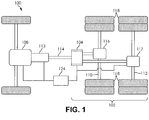
- FIG. 1 illustrates a vehicle driveline 100 fitted with a tandem axle assembly 102.
- the tandem axle assembly 102 includes a dual range axle disconnect system 104.
- the tandem axle assembly 102 may be operated in a first drive ratio and a second drive ratio.
- the dual range axle disconnect system 104 includes a planetary inter-axle differential 106 (henceforth abbreviated as PIAD, shown in FIG. 2 ) that transfers a driving torque from a power source 108 (for example, an internal combustion engine) to both a front axle 110 and a rear axle 112 of the tandem axle assembly 102.
- PIAD planetary inter-axle differential
- a power source output shaft (not shown) is drivingly engaged with an input shaft (not shown) of a transmission 113. It is understood that the transmission 113 may be either an automatic transmission or a manual transmission.
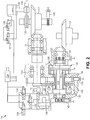
- a transmission output shaft 114 is drivingly engaged with an input shaft 115 (shown in FIG. 2 ) of the dual range axle disconnect system 104.
- the input shaft 115 is drivingly engaged with the PIAD 106.
- the PIAD 106 divides a transmitted power between the front axle 110 and the rear axle 112 of the tandem axle assembly 102.
- a first differential gear box 116 provides an exemplary axle reduction ratio of 2.64:1; however, it is understood that other ratios may be selected.
- a second differential gear box 117 provides an exemplary axle reduction ratio of 3.55:1; however, it is understood that other ratios may be selected.
- the differential gear boxes 116, 117 provide a side-to-side differential action between portions of the axles 110, 112. The portions of the axles 110, 112 are drivingly engaged with wheels 118, which provide traction to drive a vehicle (not shown) the vehicle driveline 100 is incorporated in.
- the PIAD 106 provides an effective final drive ratio of 3.1:1 in a 6x4 mode of operation and 2.64:1 in a 6x2 mode of operation; however, it is understood that the tandem axle assembly 102 may be configured for other drive ratios. Further, as a non-limiting example, the differential gear boxes 116, 117 may have identical reduction ratios, and therefore the PIAD 106 may not be needed. Additionally, it is understood that an axle ratio reduction of the tandem axle assembly 102 may occur at another portion of each of the axles 110, 112 besides the differential gear boxes 116, 117.
- the dual range axle disconnect system 104 includes the input shaft 115 that receives an output torque from the power source 108.
- a ring gear 119 of the PIAD 106 is drivingly engaged with a front axle input shaft 120 for transferring a driving torque from the PIAD 106 to the front axle 110; however, it is understood that the PIAD 106 may have other arrangements and that the dual range axle disconnect system 104 is not limited to the embodiment illustrated in FIG. 2 .
- the input 115 shaft of the PIAD 106 can be selectively engaged with or disconnected from a rear axle input shaft 121 under certain conditions to provide the 6x4 mode of operation or the 6x2 mode of operation.
- the dual range axle disconnect system 104 includes an axle disconnect device 122 which is used to drivingly disengage a portion of the rear axle 112 from the dual range axle disconnect system 104. Drivingly disengaging a portion of the rear axle 112 from the dual range axle disconnect system 104 prevents the rear axle 112 from back-driving the PIAD 106 in the 6x2 mode of operation, which results in decreased friction losses and decreased parasitic losses.
- the dual range axle disconnect system 104 may be placed in the first drive ratio or the second drive ratio.
- the dual range axle disconnect system 104 When in a higher effective numeric drive ratio (as a non-limiting example, the higher effective numeric drive ratio may be 3.1:1), the dual range axle disconnect system 104 is operating in the 6x4 mode of operation, and both the front axle 110 and the rear axle 112 provide a traction force for the vehicle the vehicle driveline 100 is incorporated in.
- the dual range axle disconnect system 104 When in a lower numeric drive ratio (as a non-limiting example, the lower effective numeric drive ratio may be 2.64:1), the dual range axle disconnect system 104 is operating in the 6x2 mode of operation, and only the front axle 110 provides a traction force for the vehicle the vehicle driveline 100 is incorporated in; however, it is understood that the vehicle driveline 100 may be configured to drive the rear axle 112 in the 6x2 mode of operation. The vehicle will typically be in the 6x4 mode of operation during a vehicle start and a vehicle acceleration (up to a cruising speed).
- a controller 124 in communication with the dual range axle disconnect system 104 determines an optimal condition for engagement or disengagement of the rear axle 112 in the dual range axle disconnect system 104. It is understood that the controller 124 may comprise a plurality of controllers in communication with one another.
- an automatic mode (which may also be referred to as a premium dual range disconnect mode)
- the tandem axle assembly 102 is shifted to the 6x2 mode of operation, which has the lower numeric drive ratio.
- a control logic of the controller 124 can be modified to solely engage or disengage the axle disconnect device 122 without disconnecting the rear axle input shaft 121.
- Such a mode of operation which may be referred to as an engage/disengage mode, may also be used for a recovery procedure.
- the dual range axle disconnect system 104 waits for an operator of the vehicle to initiate a shifting procedure.
- the dual range axle disconnect system 104 also provides the ability for a shift into the 6x2 mode of operation to be performed at a lower transmission gear, allowing subsequent transmission shifts to occur after the shift of the dual range axle disconnect system 104.
- Such features apply to both the premium dual range disconnect mode and the shift from the 6x4 mode of operation to the 6x2 mode of operation.
- axle upshift may be used to refer to the premium dual range disconnect mode, for example, in disconnecting both the axle disconnect device 122 and the rear axle input shaft 121 or the on demand axle engagement/disengagement system in which only the axle disconnect device 122 is disengaged.
- the state of the vehicle after the axle upshift has occurred is the 6x2 mode of operation.
- axle downshift refers to both the premium dual range disconnect mode, for example, in engaging both the axle disconnect device 122 and restoring drive to the rear axle input shaft 121 or the on demand axle engagement/disengagement system downshift in which only the axle disconnect device 122 is engaged.
- the state of the vehicle after the downshift is completed is the 6x4 mode of operation.
- a range position sensor 126 outputs a fixed frequency, variable duty rate signal that can be used to measure an actual position of a master actuator 128.
- the rear axle 112 includes a switch 130 that indicates an engagement status of the axle disconnect device 122.
- the axle disconnect device may be dog clutch; however, it is understood that other types of clutches may be used.
- the master actuator 128 and a rear axle actuator 132 are double sided pneumatic actuators each having an inlet controlled by a plurality of solenoid valves 135, 136, 137, 138.
- a front axle slave actuator 140 is a pneumatic actuator having an inlet controlled by the solenoid valve 134. Further, a position of the front axle slave actuator 140 may also be adjusted using the solenoid valve 135 or by the solenoid valve 136 through the master actuator 128.
- the front axle slave actuator 140 has a diameter larger than the master actuator 128 and holds the master actuator 128 in an intermediate position allowing a neutral state in which synchronization can occur.
- the actuators 128, 140 maintain their states when the solenoid valves 134, 135, 136 are turned off.
- a plurality of sensors 142, 143, 144, 145 are speed sensors which are respectively used to measure a rotational speed of the input shaft 115, a step-up gear 146, the front axle input shaft 120, and the rear axle 112.
- the dual range axle disconnect system 104 further includes a front synchronizer 150 and a rear synchronizer 152.
- a shift strategy is implemented.
- the dual range axle disconnect system 104 In the automatic mode, the dual range axle disconnect system 104 must shift from the 6x4 mode of operation to the 6x2 mode of operation and back again when the appropriate operating conditions are met.
- an exemplary situation when the conditions are met may be when a speed of the vehicle the vehicle driveline 100 is incorporated in is greater than a set speed, when a torque demand for the power source 108 is stabilized within a set range, when the transmission 113 is at an allowed ratio setting, and when the dual range axle disconnect system 104 is confident the shift can be accomplished.
- other conditions related to ambient temperature and driver demand may also apply.
- the dual range axle disconnect system 104 is shifted from the 6x4 mode of operation to the 6x2 mode of operation. To accomplish this, the dual range axle disconnect system 104 creates a torque reversal in the vehicle driveline 100 and the actuators 128, 132, 140 are commanded to transition the dual range axle disconnect system 104 to the 6x2 mode of operation.
- the conditions to command the shift occur when a speed of the vehicle the vehicle driveline 100 is incorporated in has dropped below a set speed, the transmission 113 is at an allowed ratio setting, a demand by the operator of the vehicle has been stable, and when the dual range axle disconnect system 104 is confident the shift can be accomplished.
- the operator of the vehicle is able to command the dual range axle disconnect system 104 to shift from the 6x4 mode of operation to the 6x2 mode of operation and vice-versa using a dashboard switch, for example.
- the engage/disengage mode used with the axle disconnect device 122 the conditions to be met for performing the shift remain the same. Unlike the automatic mode, in the engage/disengage mode only the axle disconnect device 122 of the rear axle 112 of the tandem axle assembly 102 is disconnected and the rear axle input shaft 121 remains drivingly engaged with the power source 108 through the PIAD 106.
- a command is sent by the controller 124 for a torque break, and a signal is sent to disengage the front axle 110 and the rear axle 112.
- a dual mode hierarchical shift controller 200 (schematically illustrated in FIG. 3 ) with digital compensation and command pre-shaping is employed.
- the dual mode hierarchical shift controller 200 which at least forms a portion of the controller 124, provides the following:
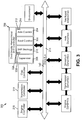
- FIG. 3 schematically illustrates a vehicle control system architecture 202 including the dual mode hierarchical shift controller 200.
- FIG. 4 schematically illustrates the dual mode hierarchical shift controller 200.
- the dual mode hierarchical shift controller 200 comprises an axle control layer 204, a boot control layer 206, a vehicle supervisor layer 208, and a shift strategy layer 210.
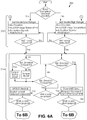
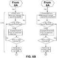
- FIGS. 6A and 6B schematically illustrates the axle control layer 204.
- the axle control layer 204 executes all of the steps necessary to perform a shift of the dual range axle disconnect system 104.
- the boot control layer 206 ensures a stable high/low range operation of the vehicle upon startup of the controller 124.
- the vehicle supervisor layer 208 monitors a health of the controller 200, performs fault detection, and executes remedial actions.
- the shift strategy layer 210 performs the tasks of modulated shift point determination, switching transmission modes, making shift decisions, and performing compensator logic.
- the axle control layer 204 consists of a finite state machine 212 and a digital compensation logic 214 that sequentially executes steps necessary for achieving the axle upshift or the axle downshift as commanded by the shift strategy layer 210.
- the finite state machine 212 broadcasts a control signal that indicates a current operating mode for the dual range axle disconnect system 104 (the 6x4 mode of operation or the 6x2 mode of operation) or if the controller 124 is being booted up.
- the axle upshift occurs in a ninth gear where the gear ratio is 1:1 (direct gear); however, it is understood that a choice of the gear ratio depends on a specific application and a hardware configuration present.
- the axle control layer 204 performs the following tasks.
- the axle control layer 204 performs the following tasks.
- FIGS. 7A and 7B schematically illustrates the boot control layer 206.
- the boot control layer 206 includes a boot control module 220 to execute a predetermined series of steps during a startup of the controller 124 and to handle any exceptions that may occur during the startup of the controller 124. Additionally, the boot control module 220 handles any exceptions (such as failures) that may occur during the operation of the vehicle the vehicle driveline 100 is incorporated in.
- the boot control module 220 handles a startup sequence for the dual range axle disconnect system 104 and also performs a recovery procedure in the event of an unexpected power loss or a reboot of the controller 124.
- the tandem axle assembly 102 When the vehicle the vehicle driveline 100 is incorporated in is placed in a shut down condition, the tandem axle assembly 102 returns to a mechanical neutral state as a result of all of the solenoid valves 134, 135, 136, 137, 138 being deactivated, consequently resulting in depressurization of all of the actuators 128, 132, 140.
- the mechanical neutral state is considered a normal startup state for the vehicle including the dual range axle disconnect system 104.
- the boot control module 220 takes control of the tandem axle assembly 102 upon startup of the vehicle and once the tandem axle assembly 102 is in one of the two stable operating configurations (the 6x4 mode of operation or the 6x2 mode of operation), the boot control module 220 passes control to the axle control layer 204 which services any further requests. Prior to passing control to the axle control layer 204, the boot control module 220 has direct control of the tandem axle assembly 102.
- An output control variable 222 of the boot control layer 206 indicates if a boot up of the dual range axle disconnect system 104 is in progress or the operating state of the dual range axle disconnect system 104 in which the boot up is completed (the 6x4 mode of operation or the 6x2 mode of operation).
- the output control variable 222 controls a switching module 224 (shown in FIG. 4 ) that mediates control of the dual range axle disconnect system 104 between the boot control layer 206 and the axle control layer 204.
- setting the vehicle to the 6x2 mode of operation or the 6x4 mode of operation includes controlling the power source 108, sending appropriate actuation signals, and confirming actuation in response to the signals. It should be noted that "setting the vehicle" to either the 6x4 mode of operation or the 6x2 mode of operation means executing all of the steps detailed in the operation of the axle control layer 204 to perform the shift.
- the vehicle supervisor layer 208 performs three functions in the dual range axle disconnect system 104.
- the vehicle supervisor layer 208 performs the following tasks:
- the vehicle supervisor layer 208 continuously monitors the operations of the dual range axle disconnect system 104 using information from the sensors 142, 143, 144, 145 to evaluate parameters critical to the tandem axle assembly 102. Some of the parameters the vehicle supervisor layer 208 monitors are:
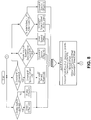
- FIG. 5 schematically illustrates the shift strategy layer 210.
- the shift strategy layer 210 performs the task of determining a modulated shift point for the dual range axle disconnect system 104.
- a proper determination of a shift point is essential for optimized fuel economy, improved behavior of the vehicle, and for a comfort of the operator of the vehicle the vehicle driveline 100 is incorporated in.
- the modulated shift-point is determined using a position of an accelerator pedal (not shown) and information from a brake switch (not shown) from an SAE J1939 data link 160; however, it is understood that the vehicle control system architecture 202 may include other types of data links.
- a shift point decision logic is modulated.
- other inputs such as a percent driver demand information, which may be obtained from the SAE J1939 data link 160 could be incorporated into determining the modulated shift point.
- the modulated shift point determination determines the point at which, other conditions permitting, an axle upshift or the axle downshift can be performed.
- a transmission mode switch 226 sets the transmission 113 to the manual mode before initiating an upshift and back to an automatic mode after a downshift (relevant to automatic transmissions).
- the shift decision monitors operating conditions and commands the axle control layer 204 when the shift must be performed.
- the transmission mode switch 226 of the shift strategy layer 210 sets the transmission 113 to the manual mode before initiating the upshift and back to the automatic mode after the downshift (relevant when the transmission 113 is an automatic transmission).
- an electronic control unit sends out power source control messages at a predefined interval, even when a shift is not in progress. The same messages are used by the axle control layer 204 to perform the shift; the transmission 113 must be controlled to prevent it from interfering with the shift of the dual range axle disconnect system and also the 6x2 mode of operation.
- a relay switch may be connected to a console of the transmission 113 or connected to a digital output port of the controller 124, which enables the controller 124 to directly control the mode of the transmission 113.
- the shift point decision logic sends a timed pulse to a plurality of relay switches connected to a plurality of push buttons on a console of the transmission 113 to set the transmission 113 to the manual mode.
- the mode of the transmission 113 is switched to the manual mode in advance of the axle upshift, stays in the manual mode throughout the 6x2 mode of operation, and is then switched back to the automatic mode after the axle downshift has occurred.
- the transmission 113 should still be able to shift until a time when it is appropriate to perform the subsequent axle shift. In this case, the transmission 113 is placed back into the automatic mode once the axle shift is complete.
- the shift strategy layer 210 includes a shift decision logic module 228.
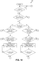
- FIG. 10 is a schematic illustration of the shift decision logic module 228 forming a portion of the shift strategy layer 210.
- the shift decision logic module 228 monitors a speed of the power source 108, an operating mode of the transmission 113, a mode of the dual range axle disconnect system 104 (the 6x4 mode of operation or the 6x2 mode of operation), and a current gear of the transmission 113. When certain conditions are present, the shift decision logic module 228 sends a signal to the axle control layer 204 to begin executing a shift. An output variable is then read by the axle control layer 204 and executes the actions corresponding to the request. The output variable can take on a plurality of different values based on the desired operating conditions.
- FIG. 11 is a schematic illustration of the vehicle control system architecture including the dual mode hierarchical shift controller 200, the power source controller 218, and a transmission controller 219.
- the power source controller 218 and the transmission controller 219 are vehicle level controllers of the vehicle the vehicle driveline 100 is incorporated in.
- the shift strategy layer 210 may further comprise a modulated shift point determination algorithm which uses a vehicle torque demand information such as the position of the accelerator or other signals from the SAE J1939 data link 160 to automatically determine the shift points for the axle upshift and the axle downshift (as described hereinabove).
- a modulated shift point determination algorithm which uses a vehicle torque demand information such as the position of the accelerator or other signals from the SAE J1939 data link 160 to automatically determine the shift points for the axle upshift and the axle downshift (as described hereinabove).
- the shift strategy layer 210 may further comprise a method by which different vehicle sensor signals and parameters are combined to determine the optimal upshift and downshift performance variables and parameters.
- the shift strategy layer 210 may further comprise a method for optimization of upshift and downshift performance through control compensation (as described hereinabove) and the resulting effect on the control logic in other layers of dual mode hierarchical shift controller 200.
- the shift strategy layer 210 may further comprise a method for selection of a power source control mode and a control compensation strategy for the a dual range axle disconnect system 104 based on a desired response behavior of the power source 108 in relation to a current behavior of the power source 108; and a method for selection of a transmission override mode to switch the transmission 113 from the automatic mode to the manual mode of the axle disconnect operation before commencing an axle shift operation to prevent a shift operation of the transmission 113 during a shifting of the dual range axle disconnect system 104.
- FIG. 12 schematically illustrates a plurality of control strategies that are required when the transmission 113 is a manual transmission.
- FIG. 12 illustrates a dual mode hierarchical shift controller 300 forming a portion of a vehicle control system architecture 302 according to another embodiment of the invention.
- the embodiment shown in FIG. 12 includes similar components to the vehicle control system architecture 302 illustrated in FIG. 3 . Similar features of the embodiment shown in FIG. 3 are numbered similarly in series, with the exception of the features described below.
- the transmission 113 does not typically include a transmission controller in communication with the vehicle controller (not shown) via the vehicle controller network 216.
- Information such as a current transmission gear ratio, a transmission output shaft speed, a transmission shift in progress, a current gear, and a selected gear are not available to the dual mode hierarchical shift controller 300.
- Such information is therefore inferred from information which is available on the vehicle controller network 216 or through a use of hardware modification. As a non-limiting example, the information may be inferred through the use of a plurality of speed sensors or other sensors.
- a result of the transmission 113 not having the transmission controller is that the controller 124 of the dual range axle disconnect system 104 cannot inhibit the operator from performing a shift of the transmission 113 in the middle of a shift of the dual range axle disconnect system 104. Similarly, the operator cannot inhibit the controller 124 from performing the shift of the dual range axle disconnect system 104 so that the transmission 113 may be shifted.
- the dual range axle disconnect system 104 cannot be prevented from shifting during a shift of the transmission 113 as there is no way controller 124 of the dual range axle disconnect system 104 to detect a shift of the transmission 113 in progress.
- a first option employs existing sensor data to infer a torque in the vehicle driveline 100 through a driveline estimation layer 303 which employs an online torque estimation algorithm, that when used with the dual mode hierarchical shift controller 300 shown in FIG. 12 will allow one to determine if the vehicle driveline 100 is in an active transmission shift process or if the vehicle driveline 100 is in a neutral condition. In the neutral condition, automated dual range disconnect shifts are possible for the dual range axle disconnect system 104.
- a second option employs a signal processing layer 305 which employs signal processing techniques to infer an amplitude shift and a phase shift, which tends to be different for the vehicle driveline 100 in a fully engaged condition versus the vehicle driveline 100 in a disengaged condition.
- a signal processing layer 305 which employs signal processing techniques to infer an amplitude shift and a phase shift, which tends to be different for the vehicle driveline 100 in a fully engaged condition versus the vehicle driveline 100 in a disengaged condition.
- a third option employs interpreting driveline frequency signatures (which can be directly used in an online digital signal processing algorithm) to discern the vehicle driveline 100 in the fully engaged condition from the vehicle driveline 100 in a disengaged condition. Using such information, it is possible to implement a decision logic which will allow shifting of the dual range axle disconnect system 104 to be automated.
- the dual mode hierarchical shift controller 300 for axle shift decision logic may further comprise a vehicle supervisor layer 308 which provides system level monitoring and control to ensure that the vehicle control system architecture 302 provides consistent safe and reliable operation and a shift strategy layer 310 (for control of the axle upshift and the axle downshift) which interfaces an axle control layer 304 and a shift strategy layer 310 with the vehicle supervisor layer 308.
- vehicle supervisory layer 308 may also be referred to as a power source management and transmission over-ride layer.
- a method for fully automatic and/or on-demand shifts from the 6x4 mode of operation to the 6x2 mode of operation and from the 6x2 mode of operation to the 6x4 mode of operation in the dual mode hierarchical shift controller 200, 300 having the vehicle supervisor layer 208, 308 may further comprise at least one unique algorithm and decision logic (as described hereinabove) to ensure that the dual mode hierarchical shift controller 200, 300 provides consistent, safe and reliable system operation.
- the at least one unique algorithms and decision logic uses various system data and parameters from each of the layers 204, 106, 208, 210, 303, 304, 305, 306, 308, 310 of the dual mode hierarchical shift controller 200, 300 to ensure performance of the vehicle control system architecture 202, 302 to specifications.
- the at least one unique algorithms and decision logic ensures a fail-soft operation in the event of a fault of one of the sensors 142, 143, 144, 145, the actuators 128, 132, 140, or a fault of the vehicle control system architecture 202, 302.
- a method for fully automatic and/or on-demand shifts from the 6x4 mode of operation to the 6x2 mode of operation and from the 6x2 mode of operation to the 6x4 mode of operation in the dual mode hierarchical shift controller 200, 300 having the vehicle supervisor layer 208, 308 may further comprise the shift strategy layer 210, 310 (for control of the axle upshift and the axle downshift) which interfaces the axle control layer 204, 304 and a shift decision logic module 228, 328 with the vehicle supervisor layer 208, 308.
- the shift strategy layer 210, 310 further comprises a method and process to obtain information from the sensors 142, 143, 144, 145 and determine an optimal mode for the dual range axle disconnect system 104 (the 6x4 mode of operation or the 6x2 mode of operation) for current operating conditions of the vehicle the vehicle driveline 100 is incorporated in.
- a method for fully automatic and/or on-demand shifts from the 6x4 mode of operation to the 6x2 mode of operation and from the 6x2 mode of operation to the 6x4 mode of operation in the dual mode hierarchical shift controller 200, 300 having the vehicle supervisor layer 208, 308 may further comprise may further comprise a method which uses various speed data of components of the tandem axle assembly 102 to make decisions for engagement and disengagement of the axle disconnect device 122 based on synchronizer speed errors, a method which uses positions of the actuators 128, 132, 140 to determine stable states of the vehicle such as the 6x4 mode of operation, the 6x2 mode of operation, a double neutral mode, an intermediate transition states (between the stable states), and a logic engine which combines the axle control layer 304 with a decision logic from higher layers such as a power source dynamics layer and a transmission override layer to enable various stable states of the dual range axle disconnect system 104 (such as the 6x4 mode of operation, the 6x2 mode of operation, and the double neutral mode).
- a method for fully automatic and/or on-demand shifts from the 6x4 mode of operation to the 6x2 mode of operation and from the 6x2 mode of operation to the 6x4 mode of operation in the dual mode hierarchical shift controller 200, 300 having the vehicle supervisor layer 208, 308 may further comprise a method to ensure startup of the dual range axle disconnect system 104 in one of the stable operating states (such as the 6x4 mode of operation or the 6x2 mode of operation), determined using positions of the actuators 128, 132, 140 and a logic engine to recognize a plurality of specific startup scenarios and execute an appropriate recovery action.
- the stable operating states such as the 6x4 mode of operation or the 6x2 mode of operation
- a method for fully automatic and/or on-demand shifts from the 6x4 mode of operation to the 6x2 mode of operation and from the 6x2 mode of operation to the 6x4 mode of operation in the dual mode hierarchical shift controller 200, 300 having the vehicle supervisor layer 208, 308 may further comprise a specific method by which the solenoid valves 134, 135, 136 are combined with the actuators 128, 140 to transition the dual range axle disconnect system 104 between three stable states (the 6x4 mode of operation, the 6x2 mode of operation, and the double neutral mode), nine transient states, and a combination of the method described hereinabove for control of the front axle 110 with engagement and disengagement of the rear axle 112 based on a speed sensing of at least one of the axles 110, 112 using one of the sensors 144, 145, and a calculation of various effective drive ratios and therefore synchronizer up-stream and down-stream speed values.
- the synchronizer up-stream and down-stream speed values are compared with a power source broadcast speed using an
- a method for fully automatic and/or on-demand shifts from the 6x4 mode of operation to the 6x2 mode of operation and from the 6x2 mode of operation to the 6x4 mode of operation in the dual mode hierarchical shift controller 200, 300 having the vehicle supervisor layer 208, 308 may further comprise may further comprise a method and apparatus for an on-demand shift from the 6x4 mode of operation to the 6x2 mode of operation and from the 6x2 mode of operation to the 6x4 mode of operation using the dual mode hierarchical shift controller 200, 300.
- the method further comprises the step of using the vehicle supervisor layer 208, 308 for a monitoring function, a control and a safety function, the vehicle supervisor layer 208, 308 using at least one algorithm and a decision logic to provide a consistent, safe and reliable operation of the dual range axle disconnect system 104.
- a method for fully automatic and/or on-demand shifts from the 6x4 mode of operation to the 6x2 mode of operation and from the 6x2 mode of operation to the 6x4 mode of operation in the dual mode hierarchical shift controller 200, 300 having the vehicle supervisor layer 208, 308 may further comprise using various vehicle system data from the sensors 142, 143, 144, 145 and parameters from the layers 204, 206, 208, 210, 303, 304, 305, 306, 308, 310 of the dual mode hierarchical shift controller 200, 300 to ensure system performance to specifications and ensure a fail safe operation in the event of a fault of one of the sensors 142, 143, 144, 145, the actuators 128, 132, 140, or a fault of the vehicle control system architecture 202, 302.
- a method for fully automatic and/or on-demand shifts from the 6x4 mode of operation to the 6x2 mode of operation and from the 6x2 mode of operation to the 6x4 mode of operation in the dual mode hierarchical shift controller 200, 300 having the vehicle supervisor layer 208, 308 may further comprise a method and apparatus for on-demand shift from the 6x4 mode of operation to the 6x2 mode of operation and from the 6x2 mode of operation to the 6x4 mode of operation using the in the dual mode hierarchical shift controller 200, 300, the method further comprising the step of using the shift strategy layer 208, 308 (which comprises at least one algorithm and decision logic) for reading or monitoring various vehicle sensor data and parameters to determine the feasibility of executing the axle shift by the operator, selection a control mode of the power source 108, and implementing a dual range disconnect control compensation strategy based on a desired power source response behavior in relation to current power source behavior.
- the method further comprises selection of the transmission mode switch 226 to switch the transmission 113 from the automatic mode to the manual mode before commencing
- a method for fully automatic and/or on-demand shifts from the 6x4 mode of operation to the 6x2 mode of operation and from the 6x2 mode of operation to the 6x4 mode of operation in the dual mode hierarchical shift controller 200, 300 having the vehicle supervisor layer 208, 308 may further comprise a method and apparatus for on-demand shift from the 6x4 mode of operation to the 6x2 mode of operation and from the 6x2 mode of operation to the 6x4 mode of operation using the dual mode hierarchical shift controller 200, 300, the method further comprising the step of using various speed data of components of the tandem axle assembly 102 to make decisions for an engagement and a disengagement of the axle disconnect device 122 based on speed errors of the synchronizers 150, 152.
- a method for fully automatic and/or on-demand shifts from the 6x4 mode of operation to the 6x2 mode of operation and from the 6x2 mode of operation to the 6x4 mode of operation in the dual mode hierarchical shift controller 200, 300 having the vehicle supervisor layer 208, 308 may further comprise a method and apparatus for on-demand shift from the 6x4 mode of operation to the 6x2 mode of operation and from the 6x2 mode of operation to the 6x4 mode of operation using the dual mode hierarchical shift controller 200, 300, the method further comprising the step of using positions of the actuators 128, 132, 140 to determine a stable state of the dual range axle disconnect system 104, such as the 6x4 mode of operation, the 6x2 mode of operation, the double neutral mode, and the intermediate transition states (between the stable states).
- the method for fully automatic and/or on-demand 6 x 4 to 6 x 2 shifts and 6 x 2 to 6 x 4 shift in a tandem axle assembly having the vehicle supervisor layer 208, 308 may further comprise a method and apparatus for on-demand shift from the 6 x 4 mode to the 6 x 2 mode shift (upshift) and the 6 x 2 mode to the 6 x 4 shift (downshift) in a tandem axle assembly using the dual mode hierarchical shift controller 200, 300, further comprising a logic engine which combines information from the axle level control layer 204, 304 with the decision logic from higher layers such as the power source dynamics layer and the transmission override layer to enable various stable states of the dual range axle disconnect system 104 (such as the 6x4 mode of operation, the 6x2 mode of operation, and the double neutral mode).
- the method for fully automatic and/or on-demand 6 x 4 to 6 x 2 shifts and 6 x 2 to 6 x 4 shift in a tandem axle assembly having the vehicle supervisor layer 208, 308 may further comprise a method and apparatus for on-demand shift from the 6 x 4 mode to the 6 x 2 mode shift (upshift) and the 6 x 2 mode to the 6 x 4 shift (downshift) in a tandem axle assembly using the dual mode hierarchical shift controller 200, 300, further comprising the step of ensuring a system startup in stable states of the dual range axle disconnect system 104 (such as the 6x4 mode of operation, the 6x2 mode of operation, and the double neutral mode), determined using positions of the actuators 128, 132, 140.
- a system startup in stable states of the dual range axle disconnect system 104 such as the 6x4 mode of operation, the 6x2 mode of operation, and the double neutral mode
- the dual mode hierarchical shift controller 200, 300 may also include a logic engine which recognizes specific startup scenarios and execute appropriate recovery actions, a control module (which may be a microcontroller based system with RAM and ROM) which can be configured to provide automatic and/or on-demand axle disconnect and engage operations in the vehicle fitted with the tandem axle assembly 102, at least one input interface (which comprises signal conditioning circuitry) to one or more speed, position, pressure and temperature sensors forming a portion of the vehicle, a connection to the vehicle controller network 216 (which is typically SAE J1939, for monitoring and controlling other vehicle systems such as the power source 108 and/or the transmission 108), at least one output interface (which comprises power driver circuitry) to one or more ON/OFF type pneumatic actuators distributed throughout the vehicle, and a processor connected to the at least one input face and the at least one output interface and memory.
- a control module which may be a microcontroller based system with RAM and ROM
- a control module which can be configured to provide automatic and/or on-demand axle disconnect and
- the processor is configured to execute a multi-tiered control system software that monitors signals received from the sensors 142, 143, 144, 145, the input interface to determine whether the 6x4 mode of operation or the 6x2 mode of operation is required.
- the processor then executes a developed finite state machine logic to actuate the actuators 128, 132, 140 to move the tandem axle assembly 102 from a current stable mode of operation to a desired stable mode of operation.
- the method for fully automatic and/or on-demand 6 x 4 to 6 x 2 shifts and 6 x 2 to 6 x 4 shift in a tandem axle assembly which includes the dual mode hierarchical shift controller 200, 300 comprising of a plurality of shift strategies based upon interaction of components of the tandem axle assembly 102 combined with higher level control strategies of the power source 108 and the transmission 113 to manipulate variables and parameters of the vehicle driveline 100, where conditions the vehicle is operating in require the 6x2 mode of operation.
- the conditions the vehicle is operating in that require the 6x2 mode of operation include operation of the vehicle at the cruising speed and operation of the vehicle at low to medium grade (in the absence of ABS events, a rain condition, and a snow condition).
- the dual range axle disconnect system 104 including the dual mode hierarchical shift controller 200, 300 provides many operational benefits for the vehicle incorporating the dual range axle disconnect system 104, such as, but not limited to, the following conditions:
- the dual range axle disconnect system 104 including the dual mode hierarchical shift controller 200, 300 takes into account a plurality of operating conditions of the vehicle to provide an optimal engagement of the rear axle (the axle downshift) and disengagement of the rear axle (the axle upshift).
- the dual mode hierarchical shift controller 200, 300 combines logic and digital compensators that cooperate to perform a smooth shift of the dual range axle disconnect system 104.
- the digital compensators act upon feedback information from the sensors 142, 143, 144, 145 as well as vehicle system variable information obtained from the power source 108, the transmission 113, or other components of the vehicle to provide a phase compensation and a gain compensation to ensure a smooth response.
- the combined logic and compensator strategy allows the sensing, the actuation, and the control elements to be non-co-located, for example, where the power source is the controlled element and the sensing and actuation occurs at the axle level of the vehicle.
- the compensator structure may be a digital PID (proportional-integral-derivative) controller or a digital transfer function of the 1st, 2nd, 3rd or higher order without PID compensation to achieve the phase compensation and the gain compensation for a desired control behavior.
- An objective of the axle control logic and the digital compensation is to manipulate the plurality of control variables to achieve the axle upshift and the axle downshift in a smooth manner.
- a driveline torque and a driveline speed may be manipulate while ensuring that there are no safety critical vehicle control functions that would preclude a shifts of the dual range axle disconnect system 104.
- a native bandwidth of the controller 218 of the power source 108 and a controller 219 of the transmission 113 (where applicable) with their associated decision logic must also be taken into account.
- the controller may have several override modes such as speed control, torque control, or speed/torque limit control.
- the dual mode hierarchical shift controller 200, 300 has to select the appropriate control mode (to ensure proper range of axle speed and torque values for both upstream and downstream of the synchronizers 150, 152) along with appropriate digital compensators and finite state machine logic, so that the dual mode hierarchical shift controller 200, 300 does not adversely affect responses from the power source 108 or the transmission 1 3. Also, since upstream dynamic systems such as the power source 108 and the transmission 113 have higher bandwidth, any control manipulation of the power source 108 which may have an effect on axle response requires that the axle control compensators provide an appropriate phase margin and an appropriate gain margin to ensure smooth shifting of the dual range axle disconnect system 104. It is also important for the dual mode hierarchical shift controller 200, 300 to take into account any intermediate dynamics which may occur between the power source 108 and the tandem axle assembly 102.
Landscapes
- Engineering & Computer Science (AREA)
- Transportation (AREA)
- Mechanical Engineering (AREA)
- Chemical & Material Sciences (AREA)
- Combustion & Propulsion (AREA)
- Automation & Control Theory (AREA)
- Physics & Mathematics (AREA)
- Mathematical Physics (AREA)
- Control Of Transmission Device (AREA)
Applications Claiming Priority (3)
| Application Number | Priority Date | Filing Date | Title |
|---|---|---|---|
| US201261721589P | 2012-11-02 | 2012-11-02 | |
| US201361794302P | 2013-03-15 | 2013-03-15 | |
| PCT/US2013/067983 WO2014071139A1 (en) | 2012-11-02 | 2013-11-01 | Hierarchical control system and method for a tandem axle drive system |
Publications (2)
| Publication Number | Publication Date |
|---|---|
| EP2914452A1 EP2914452A1 (en) | 2015-09-09 |
| EP2914452B1 true EP2914452B1 (en) | 2019-02-27 |
Family
ID=49554530
Family Applications (1)
| Application Number | Title | Priority Date | Filing Date |
|---|---|---|---|
| EP13789462.2A Not-in-force EP2914452B1 (en) | 2012-11-02 | 2013-11-01 | Hierarchical control system and method for a tandem axle drive system |
Country Status (5)
| Country | Link |
|---|---|
| US (1) | US9020715B2 (enExample) |
| EP (1) | EP2914452B1 (enExample) |
| CN (1) | CN104781098B (enExample) |
| IN (1) | IN2015DN02979A (enExample) |
| WO (1) | WO2014071139A1 (enExample) |
Families Citing this family (23)
| Publication number | Priority date | Publication date | Assignee | Title |
|---|---|---|---|---|
| WO2016022292A1 (en) * | 2014-08-04 | 2016-02-11 | Borgwarner Inc. | Tandem axles with disconnects |
| WO2017027764A1 (en) * | 2015-08-12 | 2017-02-16 | Dana Heavy Vehicle Systems Group, Llc | Control system and shift strategy for a three mode dual range disconnect axle system |
| US20170087984A1 (en) * | 2015-09-28 | 2017-03-30 | Dana Heavy Vehicle Systems Group, Llc | Tandem axle gearing arrangement to reduce drive pinion bearing parasitic losses |
| US20180249758A1 (en) * | 2017-03-05 | 2018-09-06 | SMB Labs, LLC | Dynamically Responsive Smoking Apparatus and Method of Affixing Electronics Thereon |
| US10850735B2 (en) * | 2017-04-11 | 2020-12-01 | Dana Heavy Vehicle Systems Group, Llc | Axle range shift-assist for auxiliary braking |
| US10613489B2 (en) * | 2017-06-20 | 2020-04-07 | Baidu Usa Llc | Method and system for determining optimal coefficients of controllers for autonomous driving vehicles |
| US10513146B2 (en) | 2017-08-03 | 2019-12-24 | Arvinmeritor Technology, Llc | Axle assembly having a countershaft |
| US10585433B2 (en) * | 2017-08-28 | 2020-03-10 | Ford Global Technologies, Llc | Methods and apparatus for automotive drive mode selection |
| US10369885B2 (en) | 2017-10-17 | 2019-08-06 | Arvinmeritor Technology, Llc | Axle assembly having a gear reduction unit and an interaxle differential unit |
| US10364872B2 (en) | 2017-10-17 | 2019-07-30 | Arvinmeritor Technology, Llc | Axle assembly having a gear reduction unit and an interaxle differential unit |
| US10626979B2 (en) * | 2017-10-31 | 2020-04-21 | Arvinmeritor Technology, Llc | Axle system with fluidly connected axle assemblies |
| BR102017025512B1 (pt) | 2017-11-28 | 2022-02-22 | On-Highway Brasil Ltda. | Método para monitoramento e controle de operação do eixo traseiro de um veículo |
| WO2019200389A1 (en) * | 2018-04-13 | 2019-10-17 | Dana Heavy Vehicle Systems Group, Llc | Control strategies for single and multi mode electric secondary or tag electric axles |
| US10801556B2 (en) | 2018-04-27 | 2020-10-13 | Arvinmeritor Technology, Llc | Axle assembly having a wheel end disconnect and method of control |
| US20200005632A1 (en) * | 2018-06-07 | 2020-01-02 | Intelligent Commute Llc | Traffic light adaptive learning and mapping method and system for improving vehicle energy efficiency and driving comfort |
| US10864818B2 (en) | 2018-11-14 | 2020-12-15 | Arvinmeritor Technology, Llc | Method of controlling a drive axle system |
| US10591037B2 (en) | 2018-08-09 | 2020-03-17 | Arvinmeritor Technology, Llc | Drive axle system having a planetary interaxle differential unit |
| US11052758B2 (en) | 2018-08-09 | 2021-07-06 | Arvinmeritor Technology, Llc | Method of controlling an axle assembly |
| MX2022004452A (es) * | 2019-10-18 | 2022-08-04 | Off World Inc | Sistemas y metodos para robotica industrial. |
| US11148529B1 (en) * | 2021-02-11 | 2021-10-19 | Dana Heavy Vehicle Systems Group, Llc | System and method for controlling traction of tandem axles |
| US12179583B2 (en) * | 2023-02-15 | 2024-12-31 | Dana Heavy Vehicle Systems Group, Llc | System and method for controlling a tandem axle |
| DE102023209058A1 (de) * | 2023-09-19 | 2025-03-20 | Robert Bosch Gesellschaft mit beschränkter Haftung | Hierarchische Systemarchitektur zur Steuerung eines automatisierten Fahrzeugs |
| CN118991458B (zh) * | 2024-10-18 | 2025-01-21 | 质子汽车科技有限公司 | 一种双电驱桥动力控制方法 |
Family Cites Families (6)
| Publication number | Priority date | Publication date | Assignee | Title |
|---|---|---|---|---|
| US7212896B2 (en) * | 2002-05-29 | 2007-05-01 | Ford Global Technologies, Llc | Vehicle control |
| US20070117672A1 (en) * | 2005-11-18 | 2007-05-24 | Elvins Francis J | Tandem axle system |
| FR2909065B1 (fr) * | 2006-11-27 | 2009-07-10 | Peugeot Citroen Automobiles Sa | Dispositif de pilotage pour l'amelioration de la motricite d'un vehicule. |
| KR101069779B1 (ko) * | 2009-11-09 | 2011-10-04 | 재단법인대구경북과학기술원 | Autosar 표준 플랫폼을 기반으로 하는 운전자 위치제어 시스템 및 그 설계방법 |
| US20110218715A1 (en) * | 2010-03-02 | 2011-09-08 | Shivkumar Duraiswamy | Drive train control arrangement |
| US8523738B2 (en) * | 2011-01-21 | 2013-09-03 | Dana Heavy Vehicle Systems Group, Llc | Method of shifting a tandem drive axle having an inter-axle differential |
-
2013
- 2013-11-01 CN CN201380057093.5A patent/CN104781098B/zh not_active Expired - Fee Related
- 2013-11-01 WO PCT/US2013/067983 patent/WO2014071139A1/en not_active Ceased
- 2013-11-01 EP EP13789462.2A patent/EP2914452B1/en not_active Not-in-force
- 2013-11-01 US US14/069,480 patent/US9020715B2/en active Active
- 2013-11-01 IN IN2979DEN2015 patent/IN2015DN02979A/en unknown
Non-Patent Citations (1)
| Title |
|---|
| None * |
Also Published As
| Publication number | Publication date |
|---|---|
| CN104781098A (zh) | 2015-07-15 |
| EP2914452A1 (en) | 2015-09-09 |
| CN104781098B (zh) | 2018-04-20 |
| IN2015DN02979A (enExample) | 2015-09-18 |
| US9020715B2 (en) | 2015-04-28 |
| US20140129100A1 (en) | 2014-05-08 |
| WO2014071139A1 (en) | 2014-05-08 |
Similar Documents
| Publication | Publication Date | Title |
|---|---|---|
| EP2914452B1 (en) | Hierarchical control system and method for a tandem axle drive system | |
| US8460155B2 (en) | Control apparatus for twin-clutch automatic transmission | |
| US8565986B2 (en) | System and method for operating a dual clutch transmission during failure of an engine speed sensor or a bus connection between control modules | |
| EP2653754B1 (en) | Control device for dual clutch transmission and control method for dual clutch transmission | |
| EP3381739B1 (en) | Electric-vehicle control device and control method | |
| CN104661887B (zh) | 用于操控车辆动力总成的装置和方法 | |
| EP2512895B1 (en) | Fail-to-neutral system and method for a toroidal traction drive automatic transmission | |
| US20130211680A1 (en) | Method for Setting the Working Pressure of a Transmission | |
| EP2837851B1 (en) | Transmission apparatus and method for controlling the same | |
| CN116198481A (zh) | 混动车辆的换挡控制方法、装置、系统、车辆和存储介质 | |
| JP2003211998A (ja) | 定速走行制御装置 | |
| US8556775B2 (en) | System and method for regulating torque transmission in a vehicle powertrain and a vehicle powertrain using same | |
| CN115344023A (zh) | 用于交通工具系统的诊断和控制方法 | |
| CN115773365B (zh) | 一种挡位故障解决方法及装置 | |
| CN114439928B (zh) | 一种档位控制方法、装置及车辆 | |
| EP2791555B1 (en) | Device and method for changing gears in a powertrain of a motor vehicle | |
| SE542021C2 (en) | Method for shutting down a combustion engine of a vehicle powertrain, control device, vehicle, computer program and computer readable medium | |
| US10259462B2 (en) | Method for coupling a power take-off | |
| US6971275B2 (en) | Shift control apparatus of automatic vehicle transmission | |
| CN107269835A (zh) | 混合动力车辆的变速控制装置 | |
| JP2005530111A (ja) | 自動変速システムにおける過誤ニュートラルの検出方法 | |
| JP6840565B2 (ja) | トランスミッション制御装置、制御方法及びプログラム | |
| CN108700189B (zh) | 用于在机动车的驱动系统中执行行驶速度级变换的方法和装置 | |
| JP2004270811A (ja) | クラッチ制御装置 | |
| KR20110116589A (ko) | 듀얼 클러치 변속기를 가지는 차량의 엔진 브레이크 제어 방법 |
Legal Events
| Date | Code | Title | Description |
|---|---|---|---|
| PUAI | Public reference made under article 153(3) epc to a published international application that has entered the european phase |
Free format text: ORIGINAL CODE: 0009012 |
|
| 17P | Request for examination filed |
Effective date: 20150429 |
|
| AK | Designated contracting states |
Kind code of ref document: A1 Designated state(s): AL AT BE BG CH CY CZ DE DK EE ES FI FR GB GR HR HU IE IS IT LI LT LU LV MC MK MT NL NO PL PT RO RS SE SI SK SM TR |
|
| AX | Request for extension of the european patent |
Extension state: BA ME |
|
| RIN1 | Information on inventor provided before grant (corrected) |
Inventor name: SMEDLEY, DANIEL, G. Inventor name: KRISHNAN, SAJEEV, C. Inventor name: NELLUMS, RICHARD, A. Inventor name: MARKYVECH, RONALD, K. Inventor name: RENGANATHAN, SIDHARTH Inventor name: JOSHI, SAMEER, A. Inventor name: WESOLOWSKI, STEVEN, J. Inventor name: SURIANARAYANAN, ANANTHAKRISHNAN |
|
| DAX | Request for extension of the european patent (deleted) | ||
| GRAP | Despatch of communication of intention to grant a patent |
Free format text: ORIGINAL CODE: EPIDOSNIGR1 |
|
| STAA | Information on the status of an ep patent application or granted ep patent |
Free format text: STATUS: GRANT OF PATENT IS INTENDED |
|
| INTG | Intention to grant announced |
Effective date: 20180917 |
|
| GRAS | Grant fee paid |
Free format text: ORIGINAL CODE: EPIDOSNIGR3 |
|
| GRAA | (expected) grant |
Free format text: ORIGINAL CODE: 0009210 |
|
| STAA | Information on the status of an ep patent application or granted ep patent |
Free format text: STATUS: THE PATENT HAS BEEN GRANTED |
|
| AK | Designated contracting states |
Kind code of ref document: B1 Designated state(s): AL AT BE BG CH CY CZ DE DK EE ES FI FR GB GR HR HU IE IS IT LI LT LU LV MC MK MT NL NO PL PT RO RS SE SI SK SM TR |
|
| REG | Reference to a national code |
Ref country code: GB Ref legal event code: FG4D |
|
| REG | Reference to a national code |
Ref country code: CH Ref legal event code: EP |
|
| REG | Reference to a national code |
Ref country code: AT Ref legal event code: REF Ref document number: 1100813 Country of ref document: AT Kind code of ref document: T Effective date: 20190315 |
|
| REG | Reference to a national code |
Ref country code: IE Ref legal event code: FG4D |
|
| REG | Reference to a national code |
Ref country code: DE Ref legal event code: R096 Ref document number: 602013051493 Country of ref document: DE |
|
| REG | Reference to a national code |
Ref country code: NL Ref legal event code: MP Effective date: 20190227 |
|
| REG | Reference to a national code |
Ref country code: LT Ref legal event code: MG4D |
|
| PG25 | Lapsed in a contracting state [announced via postgrant information from national office to epo] |
Ref country code: FI Free format text: LAPSE BECAUSE OF FAILURE TO SUBMIT A TRANSLATION OF THE DESCRIPTION OR TO PAY THE FEE WITHIN THE PRESCRIBED TIME-LIMIT Effective date: 20190227 Ref country code: LT Free format text: LAPSE BECAUSE OF FAILURE TO SUBMIT A TRANSLATION OF THE DESCRIPTION OR TO PAY THE FEE WITHIN THE PRESCRIBED TIME-LIMIT Effective date: 20190227 Ref country code: NL Free format text: LAPSE BECAUSE OF FAILURE TO SUBMIT A TRANSLATION OF THE DESCRIPTION OR TO PAY THE FEE WITHIN THE PRESCRIBED TIME-LIMIT Effective date: 20190227 Ref country code: NO Free format text: LAPSE BECAUSE OF FAILURE TO SUBMIT A TRANSLATION OF THE DESCRIPTION OR TO PAY THE FEE WITHIN THE PRESCRIBED TIME-LIMIT Effective date: 20190527 Ref country code: SE Free format text: LAPSE BECAUSE OF FAILURE TO SUBMIT A TRANSLATION OF THE DESCRIPTION OR TO PAY THE FEE WITHIN THE PRESCRIBED TIME-LIMIT Effective date: 20190227 Ref country code: PT Free format text: LAPSE BECAUSE OF FAILURE TO SUBMIT A TRANSLATION OF THE DESCRIPTION OR TO PAY THE FEE WITHIN THE PRESCRIBED TIME-LIMIT Effective date: 20190627 |
|
| PG25 | Lapsed in a contracting state [announced via postgrant information from national office to epo] |
Ref country code: LV Free format text: LAPSE BECAUSE OF FAILURE TO SUBMIT A TRANSLATION OF THE DESCRIPTION OR TO PAY THE FEE WITHIN THE PRESCRIBED TIME-LIMIT Effective date: 20190227 Ref country code: RS Free format text: LAPSE BECAUSE OF FAILURE TO SUBMIT A TRANSLATION OF THE DESCRIPTION OR TO PAY THE FEE WITHIN THE PRESCRIBED TIME-LIMIT Effective date: 20190227 Ref country code: HR Free format text: LAPSE BECAUSE OF FAILURE TO SUBMIT A TRANSLATION OF THE DESCRIPTION OR TO PAY THE FEE WITHIN THE PRESCRIBED TIME-LIMIT Effective date: 20190227 Ref country code: GR Free format text: LAPSE BECAUSE OF FAILURE TO SUBMIT A TRANSLATION OF THE DESCRIPTION OR TO PAY THE FEE WITHIN THE PRESCRIBED TIME-LIMIT Effective date: 20190528 Ref country code: IS Free format text: LAPSE BECAUSE OF FAILURE TO SUBMIT A TRANSLATION OF THE DESCRIPTION OR TO PAY THE FEE WITHIN THE PRESCRIBED TIME-LIMIT Effective date: 20190627 Ref country code: BG Free format text: LAPSE BECAUSE OF FAILURE TO SUBMIT A TRANSLATION OF THE DESCRIPTION OR TO PAY THE FEE WITHIN THE PRESCRIBED TIME-LIMIT Effective date: 20190527 |
|
| REG | Reference to a national code |
Ref country code: AT Ref legal event code: MK05 Ref document number: 1100813 Country of ref document: AT Kind code of ref document: T Effective date: 20190227 |
|
| PG25 | Lapsed in a contracting state [announced via postgrant information from national office to epo] |
Ref country code: EE Free format text: LAPSE BECAUSE OF FAILURE TO SUBMIT A TRANSLATION OF THE DESCRIPTION OR TO PAY THE FEE WITHIN THE PRESCRIBED TIME-LIMIT Effective date: 20190227 Ref country code: ES Free format text: LAPSE BECAUSE OF FAILURE TO SUBMIT A TRANSLATION OF THE DESCRIPTION OR TO PAY THE FEE WITHIN THE PRESCRIBED TIME-LIMIT Effective date: 20190227 Ref country code: CZ Free format text: LAPSE BECAUSE OF FAILURE TO SUBMIT A TRANSLATION OF THE DESCRIPTION OR TO PAY THE FEE WITHIN THE PRESCRIBED TIME-LIMIT Effective date: 20190227 Ref country code: RO Free format text: LAPSE BECAUSE OF FAILURE TO SUBMIT A TRANSLATION OF THE DESCRIPTION OR TO PAY THE FEE WITHIN THE PRESCRIBED TIME-LIMIT Effective date: 20190227 Ref country code: SK Free format text: LAPSE BECAUSE OF FAILURE TO SUBMIT A TRANSLATION OF THE DESCRIPTION OR TO PAY THE FEE WITHIN THE PRESCRIBED TIME-LIMIT Effective date: 20190227 Ref country code: AL Free format text: LAPSE BECAUSE OF FAILURE TO SUBMIT A TRANSLATION OF THE DESCRIPTION OR TO PAY THE FEE WITHIN THE PRESCRIBED TIME-LIMIT Effective date: 20190227 Ref country code: DK Free format text: LAPSE BECAUSE OF FAILURE TO SUBMIT A TRANSLATION OF THE DESCRIPTION OR TO PAY THE FEE WITHIN THE PRESCRIBED TIME-LIMIT Effective date: 20190227 |
|
| REG | Reference to a national code |
Ref country code: DE Ref legal event code: R097 Ref document number: 602013051493 Country of ref document: DE |
|
| PG25 | Lapsed in a contracting state [announced via postgrant information from national office to epo] |
Ref country code: SM Free format text: LAPSE BECAUSE OF FAILURE TO SUBMIT A TRANSLATION OF THE DESCRIPTION OR TO PAY THE FEE WITHIN THE PRESCRIBED TIME-LIMIT Effective date: 20190227 Ref country code: PL Free format text: LAPSE BECAUSE OF FAILURE TO SUBMIT A TRANSLATION OF THE DESCRIPTION OR TO PAY THE FEE WITHIN THE PRESCRIBED TIME-LIMIT Effective date: 20190227 |
|
| PG25 | Lapsed in a contracting state [announced via postgrant information from national office to epo] |
Ref country code: AT Free format text: LAPSE BECAUSE OF FAILURE TO SUBMIT A TRANSLATION OF THE DESCRIPTION OR TO PAY THE FEE WITHIN THE PRESCRIBED TIME-LIMIT Effective date: 20190227 |
|
| PLBE | No opposition filed within time limit |
Free format text: ORIGINAL CODE: 0009261 |
|
| STAA | Information on the status of an ep patent application or granted ep patent |
Free format text: STATUS: NO OPPOSITION FILED WITHIN TIME LIMIT |
|
| 26N | No opposition filed |
Effective date: 20191128 |
|
| PG25 | Lapsed in a contracting state [announced via postgrant information from national office to epo] |
Ref country code: SI Free format text: LAPSE BECAUSE OF FAILURE TO SUBMIT A TRANSLATION OF THE DESCRIPTION OR TO PAY THE FEE WITHIN THE PRESCRIBED TIME-LIMIT Effective date: 20190227 |
|
| PGFP | Annual fee paid to national office [announced via postgrant information from national office to epo] |
Ref country code: FR Payment date: 20191125 Year of fee payment: 7 Ref country code: IT Payment date: 20191125 Year of fee payment: 7 |
|
| PG25 | Lapsed in a contracting state [announced via postgrant information from national office to epo] |
Ref country code: TR Free format text: LAPSE BECAUSE OF FAILURE TO SUBMIT A TRANSLATION OF THE DESCRIPTION OR TO PAY THE FEE WITHIN THE PRESCRIBED TIME-LIMIT Effective date: 20190227 |
|
| PGFP | Annual fee paid to national office [announced via postgrant information from national office to epo] |
Ref country code: GB Payment date: 20191127 Year of fee payment: 7 |
|
| REG | Reference to a national code |
Ref country code: CH Ref legal event code: PL |
|
| PG25 | Lapsed in a contracting state [announced via postgrant information from national office to epo] |
Ref country code: MC Free format text: LAPSE BECAUSE OF FAILURE TO SUBMIT A TRANSLATION OF THE DESCRIPTION OR TO PAY THE FEE WITHIN THE PRESCRIBED TIME-LIMIT Effective date: 20190227 Ref country code: LI Free format text: LAPSE BECAUSE OF NON-PAYMENT OF DUE FEES Effective date: 20191130 Ref country code: CH Free format text: LAPSE BECAUSE OF NON-PAYMENT OF DUE FEES Effective date: 20191130 Ref country code: LU Free format text: LAPSE BECAUSE OF NON-PAYMENT OF DUE FEES Effective date: 20191101 |
|
| REG | Reference to a national code |
Ref country code: BE Ref legal event code: MM Effective date: 20191130 |
|
| PG25 | Lapsed in a contracting state [announced via postgrant information from national office to epo] |
Ref country code: IE Free format text: LAPSE BECAUSE OF NON-PAYMENT OF DUE FEES Effective date: 20191101 |
|
| PG25 | Lapsed in a contracting state [announced via postgrant information from national office to epo] |
Ref country code: BE Free format text: LAPSE BECAUSE OF NON-PAYMENT OF DUE FEES Effective date: 20191130 |
|
| PG25 | Lapsed in a contracting state [announced via postgrant information from national office to epo] |
Ref country code: CY Free format text: LAPSE BECAUSE OF FAILURE TO SUBMIT A TRANSLATION OF THE DESCRIPTION OR TO PAY THE FEE WITHIN THE PRESCRIBED TIME-LIMIT Effective date: 20190227 |
|
| GBPC | Gb: european patent ceased through non-payment of renewal fee |
Effective date: 20201101 |
|
| PG25 | Lapsed in a contracting state [announced via postgrant information from national office to epo] |
Ref country code: HU Free format text: LAPSE BECAUSE OF FAILURE TO SUBMIT A TRANSLATION OF THE DESCRIPTION OR TO PAY THE FEE WITHIN THE PRESCRIBED TIME-LIMIT; INVALID AB INITIO Effective date: 20131101 Ref country code: MT Free format text: LAPSE BECAUSE OF FAILURE TO SUBMIT A TRANSLATION OF THE DESCRIPTION OR TO PAY THE FEE WITHIN THE PRESCRIBED TIME-LIMIT Effective date: 20190227 |
|
| PG25 | Lapsed in a contracting state [announced via postgrant information from national office to epo] |
Ref country code: IT Free format text: LAPSE BECAUSE OF NON-PAYMENT OF DUE FEES Effective date: 20201101 Ref country code: FR Free format text: LAPSE BECAUSE OF NON-PAYMENT OF DUE FEES Effective date: 20201130 |
|
| PG25 | Lapsed in a contracting state [announced via postgrant information from national office to epo] |
Ref country code: GB Free format text: LAPSE BECAUSE OF NON-PAYMENT OF DUE FEES Effective date: 20201101 |
|
| PG25 | Lapsed in a contracting state [announced via postgrant information from national office to epo] |
Ref country code: MK Free format text: LAPSE BECAUSE OF FAILURE TO SUBMIT A TRANSLATION OF THE DESCRIPTION OR TO PAY THE FEE WITHIN THE PRESCRIBED TIME-LIMIT Effective date: 20190227 |
|
| PGFP | Annual fee paid to national office [announced via postgrant information from national office to epo] |
Ref country code: DE Payment date: 20221020 Year of fee payment: 10 |
|
| P01 | Opt-out of the competence of the unified patent court (upc) registered |
Effective date: 20230523 |
|
| REG | Reference to a national code |
Ref country code: DE Ref legal event code: R119 Ref document number: 602013051493 Country of ref document: DE |
|
| PG25 | Lapsed in a contracting state [announced via postgrant information from national office to epo] |
Ref country code: DE Free format text: LAPSE BECAUSE OF NON-PAYMENT OF DUE FEES Effective date: 20240601 |
|
| PG25 | Lapsed in a contracting state [announced via postgrant information from national office to epo] |
Ref country code: DE Free format text: LAPSE BECAUSE OF NON-PAYMENT OF DUE FEES Effective date: 20240601 |