EP2914313B1 - Unité de tirage du lait permettant le tirage du lait maternel - Google Patents
Unité de tirage du lait permettant le tirage du lait maternel Download PDFInfo
- Publication number
- EP2914313B1 EP2914313B1 EP13789745.0A EP13789745A EP2914313B1 EP 2914313 B1 EP2914313 B1 EP 2914313B1 EP 13789745 A EP13789745 A EP 13789745A EP 2914313 B1 EP2914313 B1 EP 2914313B1
- Authority
- EP
- European Patent Office
- Prior art keywords
- collection container
- milk collection
- breast shield
- coupling part
- milk
- Prior art date
- Legal status (The legal status is an assumption and is not a legal conclusion. Google has not performed a legal analysis and makes no representation as to the accuracy of the status listed.)
- Not-in-force
Links
Images


Classifications
-
- A—HUMAN NECESSITIES
- A61—MEDICAL OR VETERINARY SCIENCE; HYGIENE
- A61M—DEVICES FOR INTRODUCING MEDIA INTO, OR ONTO, THE BODY; DEVICES FOR TRANSDUCING BODY MEDIA OR FOR TAKING MEDIA FROM THE BODY; DEVICES FOR PRODUCING OR ENDING SLEEP OR STUPOR
- A61M1/00—Suction or pumping devices for medical purposes; Devices for carrying-off, for treatment of, or for carrying-over, body-liquids; Drainage systems
- A61M1/06—Milking pumps
- A61M1/062—Pump accessories
- A61M1/067—Pump accessories with means for hands-free operation
-
- A—HUMAN NECESSITIES
- A61—MEDICAL OR VETERINARY SCIENCE; HYGIENE
- A61M—DEVICES FOR INTRODUCING MEDIA INTO, OR ONTO, THE BODY; DEVICES FOR TRANSDUCING BODY MEDIA OR FOR TAKING MEDIA FROM THE BODY; DEVICES FOR PRODUCING OR ENDING SLEEP OR STUPOR
- A61M2205/00—General characteristics of the apparatus
- A61M2205/58—Means for facilitating use, e.g. by people with impaired vision
- A61M2205/586—Ergonomic details therefor, e.g. specific ergonomics for left or right-handed users
Definitions
- the present invention relates to a pumping unit for use in a device for pumping out human breast milk according to the preamble of patent claim 1, a breast cup according to the preamble of patent claim 6, a milk collecting container according to the preamble of patent claim 7 and a coupling unit according to the preamble of patent claim 8.
- Devices for pumping human breast milk are well known. There are basically two different types: the first ones are operated manually, ie the vacuum required for pumping off is generated by manual actuation of the vacuum pump. In the second types, the vacuum pump is operated by an electric motor.
- exhaust units are used which comprise a breast shield and a milk collection container connected thereto.
- the breast shield usually has a funnel for sealing engagement with the mother's breast.
- the container is detachably connected to the breast shield, either directly or via a hose connection. If the container is dimensionally stable, in particular rigid, it can be used both as a reservoir for the milk and as a lower part of a milk bottle for the administration of the milk. Such dimensionally stable containers are easy to handle, especially if they are self-standing. In other Embodiments, such containers are formed as soft bags. A disadvantage of using soft bags is that they must be treated very carefully before the tight closure, so that no milk flows out. In addition, the milk must be poured into another container before administration to a baby.
- US 2004/0087898 and WO 2008/057218 disclose pumping units with a dimensionally stable milk collection container, which is connected via a screw connection with the breast shield.
- the angle between the longitudinal central axis of the breast shield and the longitudinal central axis of the milk collection container is greater than 90 °.
- US 2008/0262420 discloses a breast shield with a milk collection chamber. This breast cap can be fastened in a brassiere. From the breastshield, a flexible conduit leads to a milk collection container, which is arranged in a belt.
- US Pat. No. 7,223,255 and WO 2008/137678 show breast shields with integrated vacuum pump and a milk collection bag, which is connected via a line with the breast shield.
- EP 1 034 807 A1 and US 2009/0171270 disclose further pumping units of the prior art.
- a discharge unit having the features of claim 1
- a breast cap having the features of claim 6
- a milk collection container having the features of claim 7
- a coupling unit having the features of claim 8.
- the inventive pumping unit for use in a device for pumping human breast milk has a breast shield for abutment with a Breast breast and a dimensionally stable or approximately dimensionally stable milk collection container for receiving the pumped breast milk.
- the breast cap has a first axis, in particular a longitudinal center axis
- the milk collection container has a second axis, in particular a longitudinal central axis.
- the milk collection container is releasably attachable to the breast shield.
- the breast cup is carried by the milk collection container or vice versa.
- the first axis is arranged in the attached state of the milk collection container at an angle to the second axis.
- the milk collecting container in the attached state is movable relative to the breast shield, whereby the angle between the first and the second axis is variable.
- the angle between the milk collection container and the breast shield can be changed, preferably adjusted as desired, it can be adjusted with regard to the individual anatomical conditions of the mother's breast.
- the mother can set before pumping out, preferably during the pumping, the optimal angle for them and also change at any time and any change in position.
- the milk collection container can be arranged relatively close to the body and to the breast shield. A long intermediate area between breast cap and container is not necessary.
- the discharge unit can thus be made compact and space-saving.
- the breast cup can even be worn under a brassiere, even though a dimensionally stable or even rigid container is arranged in close proximity to it. A so-called “hands-free” operation, in which neither container nor breastplate must be held by hand, is thus possible.
- the collection container is connected via a single interface with the breast shield.
- This interface preferably also serves as a connecting channel to direct the milk from the breast shield into the collecting container.
- a first and a second coupling part present, which together allow the relative movement, wherein the first coupling part is arranged on the breast cap and the second coupling part on the milk collection container.
- the milk collecting container preferably has a container part and a lid which closes this container part, wherein the second coupling part is arranged on the lid.
- the coupling parts form a joint and serve as connecting means which attach the milk collecting container to the breast cap.
- connection channel between the breast cup and milk collection container is provided to direct milk from the breast cup into the milk collection container, said connection channel extending through the two coupling parts. In another embodiment, however, this connection channel extends outside the two coupling parts.
- the two coupling parts are components of the milk collection container or the breast shield.
- the first coupling part is integrally formed on a part of the breast shield and / or the second coupling part is integrally formed on a part of the milk collection container.
- the breast shield may be integrally formed as a whole or consist of several parts.
- the relative movement between the milk collection container and the breast shield can take place about a single pivot axis. Preferably, it is possible around several axes. Preferably, it allows a pivoting movement in three-dimensional space.
- the relative movement is by a joint between milk collection container and breast shield allows.
- the pumping unit may be provided with a locking device for fixing the set angle.
- the joint is self-locking.
- the milk collection container is connected via a ball joint with the breast shield.
- a connecting channel is present, which connects an interior of the breast shield with an interior of the milk collection container to direct milk from the breast cup in the milk collection container.
- This connection is easy to make and disconnect and allows any tilt angle in three-dimensional space.
- a further advantage is that the ball joint, when taken apart, easy to clean. It also guarantees tightness and allows easy arrangement of the connecting channel in the joint itself.
- the ball joint has a joint ball, which is integrally formed or arranged on the breast cap, wherein the ball joint has a ball seat, which is formed or arranged in a lid of the milk collection container.
- the joint ball is formed or arranged on a lid of the milk collection container.
- the hinge is a pivoting hinge.
- the joint is a flexible connecting piece, which connects the milk collecting container with the breast shield.
- a check valve is disposed at a suitable location in the pumping unit. This check valve prevents milk from flowing back into the breast cup.
- a "suitable location” is a location which minimizes the dead volume in the breast shield and thus minimizes the space to be applied during pumping with negative pressure.
- a preferred location for the arrangement of the valve is the connecting channel.
- the valve can be used directly integrally formed or by means of a plug-in or insert element in the unit, especially in the channel, be attached.
- the valve is a duckbill valve or a diaphragm valve. Other types of valves can also be used.
- the breastshield according to the invention for use in a pumping unit described above has a coupling part which allows a relative movement between the breastshield and a milk collecting container in a state in which the milk collecting container is attached to the breastshield.
- the milk collecting container according to the invention for use in a pumping unit described above is dimensionally stable or approximately dimensionally stable and has a coupling part which allows a relative movement between the milk collecting container and a breast shield in a state in which the milk collecting container is attached to the breast shield.
- the coupling unit according to the invention for use in a pumping unit described above has a first and a second coupling part for connecting a breast shield and a dimensionally stable or approximately dimensionally stable milk collecting container, wherein the first and the second coupling part together a relative movement between the breast shield and attached to the breast cup milk collection container enable.
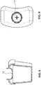
- FIGS. 1 to 3 a first embodiment of the inventive pumping unit is shown. It comprises a milk collecting container 1, 2 and a breast cap 3.
- the breast cap 3 has a first longitudinal central axis a, the milk collecting container a second longitudinal central axis b. These axes a, b are at an angle to each other.
- the milk collecting container 1 has a container part 1 with an interior for receiving the pumped milk and a lid 2 closing this container part 1.
- At least the container part 1, preferably also the cover 2 is dimensionally stable or approximately dimensionally stable. Preferably, they are relatively stiff. They usually consist of a plastic.
- the cover 2 can be releasably attached to the container part 1 in a simple embodiment.
- the container part 1 has one or more retaining ribs 10, which circulate around its upper circumference and engage in the cover 2, preferably in a corresponding circumferential groove. If the container is round, it is alternatively possible to use a rotary closure. Clamps or other fasteners are also possible.
- the container part 1 is preferably formed self-standing. He has for this purpose a stable floor area or protruding Meetingnoppen.
- the lid 2 has a lid body 20 with an upwardly directed surface. In this surface, a joint ball receptacle 21 is present.
- the joint ball receptacle 21 is formed partially spherical, with resilient brackets 210th surrounded by a round opening. This round opening leads into the interior of the container part. 1
- the breast shield 3 is also preferably made of plastic. It has an outwardly flared funnel 32 for receiving the mother's breast.
- the funnel 32 terminates in a tubular portion 39 with a vacuum port 33 for connection to a vacuum pump or to a hose leading to the vacuum pump.
- Funnel 32 and tubular portion 39 are both kept relatively small.
- the breast shield 3 is preferably integrally formed, as shown here. However, it can also be designed in several pieces.
- the breastshield 3 is preferably made of a stiff or nearly stiff material.
- the tubular part 39 is preferably rigid or at least dimensionally stable.
- This joint ball 31 is releasably held in the joint ball receptacle 21. It can be rotated within the receptacle, wherein the joint is preferably designed to be self-locking, so that the ball 31 and thus the breast cap 3 remains in a position selected by the mother relative to the container 1, 2 without further fixing means.
- This inhibition is preferably carried out by means of the resilient brackets 210.
- a connecting channel 34 extends through the neck 30 and the ball joint 31 and connects the interior 390 of the breast cap 3 with the interior 11 of the container part 1.
- a check valve here a duckbill valve 4 is arranged in the connecting channel 34. It is in this example on a shoulder of the connection channel 34. This shoulder is formed at the upper end of the connecting channel 34, ie at the transition to the tubular portion 39. As a result, the valve 4 can be introduced via the funnel 32 of the breast cap 3 to this position.
- FIGS. 4 to 6 an extended embodiment of the example described above is shown.
- the lid body 2 is equipped in this embodiment with a reversible closure 13.
- This closure 13 opens when the joint ball 31 is inserted.
- the closure 13 can be designed as resilient segments, for example, as shown here as a cross-slot membrane.
- the container can be stored for storage purposes at least approximately tight, without an additional lid is necessary.
- valve 4 is held in a push-in element 5, which can be inserted from below, ie from the other free end of the connecting channel 34.
- the channel 34 is correspondingly provided with a stop on which a circumferential shoulder of the insertion element 5 abuts.
- the insertion element 5 is preferably also made of plastic.
- the valve 4 may, as shown here, be formed as a separate part or be formed integrally with the insertion element 5.
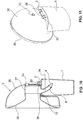
- FIG. 8 shows a preferred form of a milk collection container 1, 2, which can be used in the inventive discharge unit.
- the container part 1 preferably has a kidney-shaped cross section, so that it has an inwardly curved wall and an opposite outwardly curved wall.
- the lid 2 is formed analogously.
- the inwardly curved wall can be applied to the body of the mother, for example to the mother's breast, so that the container can be brought very close to the body.
- This container can be used in all embodiments of the inventive pumping unit described here. It can also be used in other pumping units to allow the most space-saving arrangement on the chest. It is also advantageous that several container parts 1 can be stacked in one another both in the vertical direction and can be arranged side by side in the horizontal direction without gaps. This allows them to store extremely space-saving.
- FIG. 9 is an adapter part 6 between breast cap 3 and milk collection 1, 2 arranged.
- the breast cap 3 is attached to the adapter part 6. It can be detachably connected to it so that the individual parts are separated cleaned and reassembled. However, it can not be attached to it non-destructively. This is particularly advantageous in breast caps 3, which are intended for single use or for a short-term multiple use.
- the adapter part 6 forms the neck of the breast shield 3 and has at its free end on the joint ball.
- a passage opening forms the connecting channel 34.
- This embodiment also preferably has a check valve 4. This is here again arranged at the top. However, it can also according to the insertion element 5 FIG. 7 or another valve arrangement.
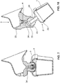
- FIGS. 10 to 12 an unclaimed further embodiment is shown.
- the milk was passed through the joint.
- the joint is arranged separately from the connection channel 34.
- the joint is formed by a hinge joint.
- On the breast cap 3, a hinge pin 38 is fixed, preferably integrally formed, which is pivotally supported in a hinge carrier 22.
- the hinge carrier 22 is in turn mounted on the lid 2 of the milk collection container, preferably also integrally formed therewith.
- the lid 2 is preferably planar, as shown in this example. He has spaced from the hinge to a passage opening 12 through which a milk line 8 protrudes.
- the milk line 8 is firmly connected to the breast shield 3. It forms the passageway 34.
- the milk line 8 is preferably a rigid or flexible tube.
- a check valve 4 is present. It may, for example, at the beginning or as shown here at the end of the milk line 8 attached to this. It is also possible to use the same breast cap 3 as in the first example. However, the variant shown is extremely space-saving and compact in this combination. It has a semicircular, preferably rigid breast cup shell 35, in which a funnel insert 36 is held. It has a peripheral edge, which is slipped over the peripheral edge of the breast cup shell 35. The narrow end of the funnel insert 36 is held in a preferably rigid funnel receptacle 37. This hopper holder 37 is mounted in the breast cup shell 35, wherein it has a nozzle which penetrates the breast cup shell 35 to the outside and the Vacuum connection 33 forms.
- the milk line 8 is integrally formed with the funnel receptacle 37 or attached thereto.
- the breast cap 3 can pivot relative to the container 1, 2 about a pivot axis.
- the passage opening 12 is dimensioned so large that the milk line 8 therein has enough leeway to join the movement without being kinked. It is not necessary that the container 1, 2 is completely closed in this area.
- the joint is formed by a flexible nozzle 7.
- the nozzle 7 preferably has lengths in the range of 20 to 50 mm.
- the nozzle is preferably formed by a hose, preferably a broadband hose, ie a flat hose.
- hose preferably a broadband hose, ie a flat hose.
- it has structures on its inside, such as longitudinal ribs, so that it does not buckle and / or the cross-section can not close. It is preferably rigid enough to automatically maintain a set position, so that the container 1, 2 can support the breast cup 3 within a certain range of pivoting angles at different pivoting angles and without external effort.
- the hose or pipe 7 on reinforcing elements are one or more wires 70, which are arranged in or on the wall of the nozzle 7.
- the nozzle 7 is attached on the one hand to the breast shield 3 and on the other hand on the lid 2 of the milk collection container. It may be releasably secured on both sides or fixedly and non-destructively releasably connected to one or both sides with these parts. Preferably, it is plugged in and has corresponding retention ribs and / or notches.
- the neck 7 preferably allows pivoting in a main direction with a slight inclination in other directions.
- a check valve 4 is preferably present. Here it is again arranged in the breast cap 3.
- the joint is in turn a ball joint.
- a joint ball 23 is arranged on the cover 2 of the milk collection container, in particular made in one piece with it.
- the breast shield 3 has a corresponding joint ball receptacle.
- the connecting channel 34 of the breast shield 3 merges into a connecting channel 24 in the ball joint 23. So that this connection remains open even with relatively large pivoting angles, the upper end of the cover-side connecting channel 24 is provided with a widening inlet funnel 25.
- the inventive exhaust unit can be compact and space-saving form and is particularly suitable in a "hands-free" arrangement.
- LIST OF REFERENCE NUMBERS 1 container part 35 Breastshield shell 10 Retaining rib 36 funnel filter 11 inner space 37 funnel recording 12 Port 38 hinge pin 13 shutter 39 tubular section 390 inner space 2 cover 20 cover body 4 Valve 21 ball seat 210 clip 5 male member 22 hinge support 23 joint ball 6 adapter part 24 connecting channel 25 inlet funnel 7 Support 70 wire 3 breastshield 30 neck 8th milk line 31 joint ball 32 funnel a first longitudinal center axis 33 vacuum connection b second longitudinal center axis 34 connecting channel
Landscapes
- Health & Medical Sciences (AREA)
- Heart & Thoracic Surgery (AREA)
- Biomedical Technology (AREA)
- Vascular Medicine (AREA)
- Engineering & Computer Science (AREA)
- Anesthesiology (AREA)
- Pediatric Medicine (AREA)
- Hematology (AREA)
- Life Sciences & Earth Sciences (AREA)
- Animal Behavior & Ethology (AREA)
- General Health & Medical Sciences (AREA)
- Public Health (AREA)
- Veterinary Medicine (AREA)
- External Artificial Organs (AREA)
- Prostheses (AREA)
Claims (8)
- Unité de tirage de lait pour l'utilisation dans un dispositif de tirage de lait maternel humain, l'unité de tirage de lait présentant une téterelle (3) destinée à être appliquée contre un sein maternel et un récipient de collecte de lait (1, 2) de forme stable ou approximativement stable pour recevoir le lait maternel tiré, la téterelle (3) présentant un premier axe médian longitudinal (a) et le récipient de collecte de lait (1, 2) présentant un deuxième axe médian longitudinal (b), le récipient de collecte de lait (1, 2) pouvant être fixé de manière amovible à la téterelle (3) et le premier axe médian longitudinal (a) étant disposé dans l'état fixé du récipient de collecte de lait (1, 2) suivant un certain angle par rapport au deuxième axe médian longitudinal (b), le récipient de collecte de lait (1, 2), pouvant être déplacé par rapport à la téterelle (3) dans l'état fixé, de sorte que l'angle entre le premier axe médian longitudinal (a) et le deuxième axe médian longitudinal (b) puisse être modifié, une première et une deuxième partie d'accouplement (31, 21 ; 23) étant prévues, lesquelles permettent ensemble le mouvement relatif, la première partie d'accouplement (31) étant disposée au niveau de la téterelle (3) et la deuxième partie d'accouplement (21, 23) étant disposée au niveau du récipient de collecte de lait (1, 2), la première partie d'accouplement (31) formant avec la deuxième partie d'accouplement (21, 23) une articulation à rotule qui relie le récipient de collecte de lait (1, 2) à la téterelle (3), un canal de liaison (24, 34) étant prévu dans l'articulation à rotule, lequel relie un espace intérieur (390) de la téterelle (3) à un espace intérieur (11) du récipient de collecte de lait (1) afin de guider le lait depuis la téterelle (3) jusque dans le récipient de collecte de lait (1, 2), caractérisée en ce qu'une position de la téterelle (3) est prévue, dans laquelle ce canal de liaison (24, 34) s'étend dans la direction du deuxième axe médian longitudinal (b), et en ce que soita) l'articulation à rotule présente une rotule d'articulation (31) qui est façonnée ou disposée sur la téterelle (3), l'articulation à rotule présentant un logement de rotule (21) qui est façonné ou disposé dans un couvercle (2) du récipient de collecte de lait (1, 2), soitb) l'articulation à rotule présente une rotule d'articulation (23) qui est façonnée ou disposée sur un couvercle (2) du récipient de collecte de lait (1, 2).
- Unité de tirage de lait selon la revendication 1, dans laquelle le récipient de collecte de lait présente une partie de récipient (1) et un couvercle (2) fermant cette partie de récipient (1).
- Unité de tirage de lait selon l'une quelconque des revendications 1 ou 2, dans laquelle la première partie d'accouplement (31) est façonnée d'une seule pièce au niveau d'une partie de la téterelle (3) et/ou la deuxième partie d'accouplement (21, 23) est façonnée d'une seule pièce au niveau d'une partie du récipient de collecte de lait (1, 2).
- Unité de tirage de lait selon l'une quelconque des revendications 1 ou 2, dans laquelle au moins l'une des deux parties d'accouplement (6) est une partie supplémentaire au récipient de collecte de lait (1, 2) et à la téterelle (3), la partie d'accouplement supplémentaire (6) présentant, dans la direction de la connexion entre le récipient de collecte de lait (1, 2) et la téterelle (3), une longueur qui est considérablement inférieure à la hauteur du récipient de collecte de lait (1, 2) et/ou de la téterelle (3).
- Unité de tirage de lait selon l'une quelconque des revendications 1 à 4, dans laquelle le récipient de collecte de lait (1, 2) présente une section transversale en forme de haricot.
- Téterelle (3) pour une unité de tirage de lait selon l'une quelconque des revendications 1 à 5, dans laquelle la téterelle (3) définit un premier axe médian longitudinal (a) et présente une première partie d'accouplement (31) qui permet un mouvement relatif entre la téterelle (3) et un récipient de collecte de lait (1, 2) dans un état dans lequel le récipient de collecte de lait (1, 2) est fixé à la téterelle (3), le récipient de collecte de lait (1, 2) définissant un deuxième axe médian longitudinal (b), la première partie d'accouplement (31) pouvant être raccordée à une deuxième partie d'accouplement (21, 23) du récipient de collecte de lait (1, 2), les deux parties d'accouplement permettant ensemble le mouvement relatif, l'angle entre le premier axe médian longitudinal (a) et le deuxième axe médian longitudinal (b), dans l'état fixé du récipient de collecte de lait (1, 2), pouvant être modifié, la première partie d'accouplement (31) formant avec la deuxième partie d'accouplement (21, 23) une articulation à rotule, un canal de liaison (24, 34) étant prévu dans l'articulation à rotule, lequel relie un espace intérieur (390) de la téterelle (3) à un espace intérieur (11) du récipient de collecte de lait (1), afin de conduire du lait depuis la téterelle (3) jusque dans le récipient de collecte de lait (1, 2), la première partie d'accouplement présentant une rotule d'articulation (31) ou un logement de rotule (21) de l'articulation à rotule et la deuxième partie d'accouplement (21, 23) présentant un logement de rotule correspondant (21) ou une rotule d'articulation (31) de l'articulation à rotule et une position de la téterelle (3) étant prévue, dans laquelle ce canal de liaison (24, 34) s'étend dans la direction du deuxième axe médian longitudinal (b), caractérisée en ce qu'une position de la téterelle (3) est prévue, dans laquelle le canal de liaison (24, 34) s'étend dans une direction qui forme un angle avec le premier axe médian longitudinal (a).
- Récipient de collecte de lait (1, 2) destiné à l'utilisation dans une unité de tirage de lait selon l'une quelconque des revendications 1 à 5, le récipient de collecte de lait (1, 2) étant réalisé sous forme stable ou approximativement sous forme stable et présentant une deuxième partie d'accouplement (21, 23) qui permet un mouvement relatif entre le récipient de collecte de lait (1, 2) et une téterelle (3) dans un état dans lequel le récipient de collecte de lait (1, 2) est fixé à la téterelle (3), le récipient de collecte de lait (1, 2) définissant un deuxième axe médian longitudinal (b), la deuxième partie d'accouplement (21, 23) pouvant être connectée à une première partie d'accouplement (31) de la téterelle (3), les deux parties d'accouplement permettant ensemble le mouvement relatif, l'angle entre le premier axe médian longitudinal (a) et le deuxième axe médian longitudinal (b) dans l'état fixé du récipient de collecte de lait (1, 2) pouvant être modifié, la première partie d'accouplement (31) formant avec la deuxième partie d'accouplement (21, 23) une articulation à rotule, un canal de liaison (24, 34) étant prévu dans l'articulation à rotule, lequel relie un espace intérieur (390) de la téterelle (3) à un espace intérieur (11) du récipient de collecte de lait (1), afin de conduire du lait depuis la téterelle (3) jusque dans le récipient de collecte de lait (1, 2), la première partie d'accouplement présentant une rotule d'articulation (31) ou un logement de rotule (21) de l'articulation à rotule et la deuxième partie d'accouplement (21, 23) présentant un logement de rotule correspondant (21) ou une rotule d'articulation (31) de l'articulation à rotule et une position de la téterelle (3) étant prévue, dans laquelle le canal de liaison (24, 34) s'étend dans la direction du deuxième axe médian longitudinal (b).
- Unité d'accouplement (31, 21 ; 23) pour l'utilisation dans une unité de tirage de lait selon l'une quelconque des revendications 1 à 5, l'unité d'accouplement (31, 21 ; 23) présentant une première et une deuxième partie d'accouplement pour la connexion d'une téterelle (3) avec un premier axe médian longitudinal (a) et d'un récipient de collecte de lait de forme stable ou approximativement de forme stable (1, 2) avec un deuxième axe médian longitudinal (b), la première et la deuxième partie d'accouplement permettant ensemble un mouvement relatif entre la téterelle (3) et le récipient de collecte de lait (1, 2) fixé à la téterelle (3), l'angle entre le premier axe médian longitudinal (a) et le deuxième axe médian longitudinal (b) dans l'état du récipient de collecte de lait (1, 2) fixé à la téterelle (3) pouvant être modifié, la première partie d'accouplement (31) formant avec la deuxième partie d'accouplement (21, 23) une articulation à rotule, un canal de liaison (24, 34) étant prévu dans l'articulation à rotule, lequel relie un espace intérieur (390) de la téterelle (3) à un espace intérieur (11) du récipient de collecte de lait (1), afin de guider le lait depuis la téterelle (3) jusque dans le récipient de collecte de lait (1, 2) et la première partie d'accouplement présentant une rotule d'articulation (31) ou un logement de rotule (21) de l'articulation à rotule et la deuxième partie d'accouplement (21, 23) présentant un logement de rotule correspondant (21) ou une rotule d'articulation (31) de l'articulation à rotule et une position de la téterelle (3) étant prévue, dans laquelle ce canal de liaison (24, 34) s'étend dans la direction du deuxième axe médian longitudinal (b).
Applications Claiming Priority (3)
| Application Number | Priority Date | Filing Date | Title |
|---|---|---|---|
| US201261722563P | 2012-11-05 | 2012-11-05 | |
| US13/828,333 US9205185B2 (en) | 2012-11-05 | 2013-03-14 | Pump unit for expressing milk |
| PCT/EP2013/072827 WO2014068066A1 (fr) | 2012-11-05 | 2013-10-31 | Unité de tirage du lait permettant le tirage du lait maternel |
Publications (2)
| Publication Number | Publication Date |
|---|---|
| EP2914313A1 EP2914313A1 (fr) | 2015-09-09 |
| EP2914313B1 true EP2914313B1 (fr) | 2018-01-03 |
Family
ID=50623014
Family Applications (1)
| Application Number | Title | Priority Date | Filing Date |
|---|---|---|---|
| EP13789745.0A Not-in-force EP2914313B1 (fr) | 2012-11-05 | 2013-10-31 | Unité de tirage du lait permettant le tirage du lait maternel |
Country Status (5)
| Country | Link |
|---|---|
| US (1) | US9205185B2 (fr) |
| EP (1) | EP2914313B1 (fr) |
| CN (1) | CN104812422B (fr) |
| TW (1) | TWI597077B (fr) |
| WO (1) | WO2014068066A1 (fr) |
Families Citing this family (12)
| Publication number | Priority date | Publication date | Assignee | Title |
|---|---|---|---|---|
| CH708400A1 (de) * | 2013-07-16 | 2015-01-30 | Medela Holding Ag | Brustpumpeneinheit. |
| US20160000980A1 (en) * | 2014-03-20 | 2016-01-07 | Naya Health, Inc. | Pump apparatus and methods for expression of human breast milk |
| EP3193707B1 (fr) * | 2014-09-16 | 2019-09-04 | ExploraMed NC7, Inc. | Système d'évaluation de volume de lait exprimé à partir d'un sein |
| EP3058967A1 (fr) | 2015-02-20 | 2016-08-24 | Medela Holding AG | unité de tire-lait et connecteur pour un tire-lait |
| CN104784766B (zh) * | 2015-05-05 | 2018-04-17 | 陈俊波 | 一种三通部件及带有这种三通部件的吸奶器 |
| CN105905409A (zh) * | 2016-03-29 | 2016-08-31 | 南京明基医院有限公司 | 接奶袋 |
| TWI675675B (zh) * | 2017-11-27 | 2019-11-01 | 黃士哲 | 隱形擠乳裝置 |
| EP3536359A1 (fr) * | 2018-03-06 | 2019-09-11 | Medela Holding AG | Tire-lait |
| CN113230524B (zh) * | 2018-12-21 | 2022-12-06 | 宿州青智网络科技有限公司 | 一种用于护理喷药装置的自适应供药机构 |
| US11523688B2 (en) * | 2020-04-17 | 2022-12-13 | Restful Pump, Inc. | Adjustable breast pump flange |
| US11759554B1 (en) * | 2021-01-21 | 2023-09-19 | Wayne D Turner | Breast shield with suckling motion one-way valve |
| US11779688B2 (en) * | 2021-01-21 | 2023-10-10 | Wayne D Turner | Breast shield |
Family Cites Families (18)
| Publication number | Priority date | Publication date | Assignee | Title |
|---|---|---|---|---|
| US4680028A (en) | 1984-07-02 | 1987-07-14 | Lact-Assist, Incorporated | Flexible breast receptor for breast pump |
| US5571084A (en) | 1994-12-12 | 1996-11-05 | Spread Spectrum Inc. | Microprocessor-controlled vested lactation system |
| EP1034807A1 (fr) | 1998-03-06 | 2000-09-13 | Ameda AG | Cloche de suction pour pompe tire-lait |
| WO1999044650A1 (fr) * | 1998-03-06 | 1999-09-10 | Ameda Ag Medical Equipment | Pompe tire-lait |
| US6073788A (en) | 1998-10-26 | 2000-06-13 | Evenflo Company, Inc. | Tactile baby bottle |
| US6092680A (en) | 1998-11-30 | 2000-07-25 | Pillado; Rodolfo Mario | Baby bottle assembly |
| USD420448S (en) * | 1999-01-15 | 2000-02-08 | Handi-Craft Company | Nursing bottle with indented sides and vent tube |
| JP2001087377A (ja) * | 1999-09-20 | 2001-04-03 | Hirose Electric Co Ltd | 脈動式搾乳器 |
| CA2451171C (fr) | 2001-06-19 | 2008-06-10 | Whisper Wear, Inc. | Systeme destine a un tire-lait mains libres, portatif, et procede d'utilisation associe |
| GB0119074D0 (en) * | 2001-08-06 | 2001-09-26 | Handley Kuester Ltd | Breast pumps |
| US6749582B2 (en) * | 2002-04-30 | 2004-06-15 | The First Years Inc. | Pumping breast milk |
| US20040087898A1 (en) | 2002-11-01 | 2004-05-06 | Gotthilf Weniger | Breast pump assembly |
| US8152754B2 (en) * | 2004-04-01 | 2012-04-10 | Medela Holding Ag | Soft breastshield |
| US7559915B2 (en) | 2004-10-13 | 2009-07-14 | Stella Dao | Breast pump device with self-contained breast milk reservoir |
| AT503143B1 (de) | 2006-01-24 | 2008-04-15 | Mam Babyartikel | Milchpumpe sowie aufsatzteil hiefür |
| US8187227B2 (en) | 2006-11-01 | 2012-05-29 | Medela Holding Ag | Self returning contamination barrier |
| MX2009011911A (es) | 2007-05-04 | 2010-03-18 | Whisper Wear Inc | Sacaleches a manos libres con transmision alternativa balanceada. |
| CN201370807Y (zh) * | 2008-12-31 | 2009-12-30 | 张强 | 自由旋转实用型吸奶器 |
-
2013
- 2013-03-14 US US13/828,333 patent/US9205185B2/en active Active
- 2013-10-31 EP EP13789745.0A patent/EP2914313B1/fr not_active Not-in-force
- 2013-10-31 CN CN201380057826.5A patent/CN104812422B/zh not_active Expired - Fee Related
- 2013-10-31 WO PCT/EP2013/072827 patent/WO2014068066A1/fr active Application Filing
- 2013-11-05 TW TW102140020A patent/TWI597077B/zh active
Also Published As
| Publication number | Publication date |
|---|---|
| WO2014068066A1 (fr) | 2014-05-08 |
| US20140128806A1 (en) | 2014-05-08 |
| TW201434502A (zh) | 2014-09-16 |
| TWI597077B (zh) | 2017-09-01 |
| US9205185B2 (en) | 2015-12-08 |
| CN104812422A (zh) | 2015-07-29 |
| EP2914313A1 (fr) | 2015-09-09 |
| CN104812422B (zh) | 2017-06-23 |
Similar Documents
| Publication | Publication Date | Title |
|---|---|---|
| EP2914313B1 (fr) | Unité de tirage du lait permettant le tirage du lait maternel | |
| EP2934616B1 (fr) | Unité de téterelle | |
| EP2911715B1 (fr) | Téterelle à séparation des milieux | |
| EP2934615B1 (fr) | Unité téterelle pourvue d'une séparation de milieux | |
| EP0374637B1 (fr) | Dispositif pour préparer un cappuccino | |
| EP3258982B1 (fr) | Tire-lait doté d'un bord souple | |
| EP3258981B1 (fr) | Adaptateur doté d'une membrane de séparation de fluides pour une téterelle | |
| EP3258984B1 (fr) | Téterelle | |
| DE3023583A1 (de) | Tauchrohr und ventil mit schnelltrennkupplung fuer einen zusammenlegbaren behaelter | |
| EP2589322A1 (fr) | Machine à café, notamment automate à espresso | |
| DE202012009075U1 (de) | Mehrwegeventil in einer Vorrichtung zur Milchschaumbereitung | |
| DE102012111429A1 (de) | Kartuschenhalterung einer Dialysemaschine mit integrierter Positionierhilfe | |
| EP2721976B1 (fr) | Sortie centrale démontable d'un dispositif de préparation de boissons | |
| EP2523585B1 (fr) | Dispositif à cheminée pour la préparation d'une boisson chaude, notamment cafetière à expresso | |
| EP2979544A1 (fr) | Systeme d'allaitement pour betail | |
| EP3045091B1 (fr) | Dispositif de préparation de boissons et procédé de fonctionnement | |
| EP3058967A1 (fr) | unité de tire-lait et connecteur pour un tire-lait | |
| EP3045092B1 (fr) | Dispositif de préparation de boissons et procédé de fonctionnement | |
| EP2987434B1 (fr) | Dispositif permettant de faire mousser et/ ou chauffer le lait et dispositif de préparation de boissons | |
| EP2268947A1 (fr) | Soupape de prélèvement d'échantillon | |
| DE102016215633B4 (de) | Melkbecherhülse und modulares Melkbecherhülsensystem | |
| DE602004005555T2 (de) | Sauger für Säuglingsflasche | |
| DE621995C (de) | Mundstueck fuer Staubsauger | |
| DE3004378A1 (de) | Saeuglingsflasche | |
| DE102004036095B3 (de) | Futtermittelbehälter für insbesondere Haustiere |
Legal Events
| Date | Code | Title | Description |
|---|---|---|---|
| PUAI | Public reference made under article 153(3) epc to a published international application that has entered the european phase |
Free format text: ORIGINAL CODE: 0009012 |
|
| 17P | Request for examination filed |
Effective date: 20150423 |
|
| AK | Designated contracting states |
Kind code of ref document: A1 Designated state(s): AL AT BE BG CH CY CZ DE DK EE ES FI FR GB GR HR HU IE IS IT LI LT LU LV MC MK MT NL NO PL PT RO RS SE SI SK SM TR |
|
| AX | Request for extension of the european patent |
Extension state: BA ME |
|
| DAX | Request for extension of the european patent (deleted) | ||
| 17Q | First examination report despatched |
Effective date: 20160226 |
|
| GRAP | Despatch of communication of intention to grant a patent |
Free format text: ORIGINAL CODE: EPIDOSNIGR1 |
|
| INTG | Intention to grant announced |
Effective date: 20170705 |
|
| GRAS | Grant fee paid |
Free format text: ORIGINAL CODE: EPIDOSNIGR3 |
|
| GRAJ | Information related to disapproval of communication of intention to grant by the applicant or resumption of examination proceedings by the epo deleted |
Free format text: ORIGINAL CODE: EPIDOSDIGR1 |
|
| GRAL | Information related to payment of fee for publishing/printing deleted |
Free format text: ORIGINAL CODE: EPIDOSDIGR3 |
|
| GRAR | Information related to intention to grant a patent recorded |
Free format text: ORIGINAL CODE: EPIDOSNIGR71 |
|
| GRAA | (expected) grant |
Free format text: ORIGINAL CODE: 0009210 |
|
| INTC | Intention to grant announced (deleted) | ||
| AK | Designated contracting states |
Kind code of ref document: B1 Designated state(s): AL AT BE BG CH CY CZ DE DK EE ES FI FR GB GR HR HU IE IS IT LI LT LU LV MC MK MT NL NO PL PT RO RS SE SI SK SM TR |
|
| INTG | Intention to grant announced |
Effective date: 20171127 |
|
| REG | Reference to a national code |
Ref country code: GB Ref legal event code: FG4D Free format text: NOT ENGLISH |
|
| REG | Reference to a national code |
Ref country code: CH Ref legal event code: EP Ref country code: AT Ref legal event code: REF Ref document number: 959646 Country of ref document: AT Kind code of ref document: T Effective date: 20180115 |
|
| REG | Reference to a national code |
Ref country code: IE Ref legal event code: FG4D Free format text: LANGUAGE OF EP DOCUMENT: GERMAN |
|
| REG | Reference to a national code |
Ref country code: CH Ref legal event code: NV Representative=s name: ISLER AND PEDRAZZINI AG, CH |
|
| REG | Reference to a national code |
Ref country code: DE Ref legal event code: R096 Ref document number: 502013009198 Country of ref document: DE |
|
| REG | Reference to a national code |
Ref country code: NL Ref legal event code: MP Effective date: 20180103 |
|
| REG | Reference to a national code |
Ref country code: LT Ref legal event code: MG4D |
|
| PG25 | Lapsed in a contracting state [announced via postgrant information from national office to epo] |
Ref country code: NL Free format text: LAPSE BECAUSE OF FAILURE TO SUBMIT A TRANSLATION OF THE DESCRIPTION OR TO PAY THE FEE WITHIN THE PRESCRIBED TIME-LIMIT Effective date: 20180103 |
|
| PG25 | Lapsed in a contracting state [announced via postgrant information from national office to epo] |
Ref country code: CY Free format text: LAPSE BECAUSE OF FAILURE TO SUBMIT A TRANSLATION OF THE DESCRIPTION OR TO PAY THE FEE WITHIN THE PRESCRIBED TIME-LIMIT Effective date: 20180103 Ref country code: HR Free format text: LAPSE BECAUSE OF FAILURE TO SUBMIT A TRANSLATION OF THE DESCRIPTION OR TO PAY THE FEE WITHIN THE PRESCRIBED TIME-LIMIT Effective date: 20180103 Ref country code: ES Free format text: LAPSE BECAUSE OF FAILURE TO SUBMIT A TRANSLATION OF THE DESCRIPTION OR TO PAY THE FEE WITHIN THE PRESCRIBED TIME-LIMIT Effective date: 20180103 Ref country code: LT Free format text: LAPSE BECAUSE OF FAILURE TO SUBMIT A TRANSLATION OF THE DESCRIPTION OR TO PAY THE FEE WITHIN THE PRESCRIBED TIME-LIMIT Effective date: 20180103 Ref country code: NO Free format text: LAPSE BECAUSE OF FAILURE TO SUBMIT A TRANSLATION OF THE DESCRIPTION OR TO PAY THE FEE WITHIN THE PRESCRIBED TIME-LIMIT Effective date: 20180403 Ref country code: FI Free format text: LAPSE BECAUSE OF FAILURE TO SUBMIT A TRANSLATION OF THE DESCRIPTION OR TO PAY THE FEE WITHIN THE PRESCRIBED TIME-LIMIT Effective date: 20180103 |
|
| PG25 | Lapsed in a contracting state [announced via postgrant information from national office to epo] |
Ref country code: SE Free format text: LAPSE BECAUSE OF FAILURE TO SUBMIT A TRANSLATION OF THE DESCRIPTION OR TO PAY THE FEE WITHIN THE PRESCRIBED TIME-LIMIT Effective date: 20180103 Ref country code: LV Free format text: LAPSE BECAUSE OF FAILURE TO SUBMIT A TRANSLATION OF THE DESCRIPTION OR TO PAY THE FEE WITHIN THE PRESCRIBED TIME-LIMIT Effective date: 20180103 Ref country code: PL Free format text: LAPSE BECAUSE OF FAILURE TO SUBMIT A TRANSLATION OF THE DESCRIPTION OR TO PAY THE FEE WITHIN THE PRESCRIBED TIME-LIMIT Effective date: 20180103 Ref country code: IS Free format text: LAPSE BECAUSE OF FAILURE TO SUBMIT A TRANSLATION OF THE DESCRIPTION OR TO PAY THE FEE WITHIN THE PRESCRIBED TIME-LIMIT Effective date: 20180503 Ref country code: BG Free format text: LAPSE BECAUSE OF FAILURE TO SUBMIT A TRANSLATION OF THE DESCRIPTION OR TO PAY THE FEE WITHIN THE PRESCRIBED TIME-LIMIT Effective date: 20180403 Ref country code: GR Free format text: LAPSE BECAUSE OF FAILURE TO SUBMIT A TRANSLATION OF THE DESCRIPTION OR TO PAY THE FEE WITHIN THE PRESCRIBED TIME-LIMIT Effective date: 20180404 Ref country code: RS Free format text: LAPSE BECAUSE OF FAILURE TO SUBMIT A TRANSLATION OF THE DESCRIPTION OR TO PAY THE FEE WITHIN THE PRESCRIBED TIME-LIMIT Effective date: 20180103 |
|
| PG25 | Lapsed in a contracting state [announced via postgrant information from national office to epo] |
Ref country code: MT Free format text: LAPSE BECAUSE OF FAILURE TO SUBMIT A TRANSLATION OF THE DESCRIPTION OR TO PAY THE FEE WITHIN THE PRESCRIBED TIME-LIMIT Effective date: 20180103 |
|
| REG | Reference to a national code |
Ref country code: DE Ref legal event code: R097 Ref document number: 502013009198 Country of ref document: DE |
|
| PG25 | Lapsed in a contracting state [announced via postgrant information from national office to epo] |
Ref country code: AL Free format text: LAPSE BECAUSE OF FAILURE TO SUBMIT A TRANSLATION OF THE DESCRIPTION OR TO PAY THE FEE WITHIN THE PRESCRIBED TIME-LIMIT Effective date: 20180103 Ref country code: IT Free format text: LAPSE BECAUSE OF FAILURE TO SUBMIT A TRANSLATION OF THE DESCRIPTION OR TO PAY THE FEE WITHIN THE PRESCRIBED TIME-LIMIT Effective date: 20180103 Ref country code: RO Free format text: LAPSE BECAUSE OF FAILURE TO SUBMIT A TRANSLATION OF THE DESCRIPTION OR TO PAY THE FEE WITHIN THE PRESCRIBED TIME-LIMIT Effective date: 20180103 Ref country code: EE Free format text: LAPSE BECAUSE OF FAILURE TO SUBMIT A TRANSLATION OF THE DESCRIPTION OR TO PAY THE FEE WITHIN THE PRESCRIBED TIME-LIMIT Effective date: 20180103 |
|
| PLBE | No opposition filed within time limit |
Free format text: ORIGINAL CODE: 0009261 |
|
| STAA | Information on the status of an ep patent application or granted ep patent |
Free format text: STATUS: NO OPPOSITION FILED WITHIN TIME LIMIT |
|
| PG25 | Lapsed in a contracting state [announced via postgrant information from national office to epo] |
Ref country code: SK Free format text: LAPSE BECAUSE OF FAILURE TO SUBMIT A TRANSLATION OF THE DESCRIPTION OR TO PAY THE FEE WITHIN THE PRESCRIBED TIME-LIMIT Effective date: 20180103 Ref country code: DK Free format text: LAPSE BECAUSE OF FAILURE TO SUBMIT A TRANSLATION OF THE DESCRIPTION OR TO PAY THE FEE WITHIN THE PRESCRIBED TIME-LIMIT Effective date: 20180103 Ref country code: CZ Free format text: LAPSE BECAUSE OF FAILURE TO SUBMIT A TRANSLATION OF THE DESCRIPTION OR TO PAY THE FEE WITHIN THE PRESCRIBED TIME-LIMIT Effective date: 20180103 Ref country code: SM Free format text: LAPSE BECAUSE OF FAILURE TO SUBMIT A TRANSLATION OF THE DESCRIPTION OR TO PAY THE FEE WITHIN THE PRESCRIBED TIME-LIMIT Effective date: 20180103 |
|
| 26N | No opposition filed |
Effective date: 20181005 |
|
| PG25 | Lapsed in a contracting state [announced via postgrant information from national office to epo] |
Ref country code: SI Free format text: LAPSE BECAUSE OF FAILURE TO SUBMIT A TRANSLATION OF THE DESCRIPTION OR TO PAY THE FEE WITHIN THE PRESCRIBED TIME-LIMIT Effective date: 20180103 |
|
| REG | Reference to a national code |
Ref country code: DE Ref legal event code: R119 Ref document number: 502013009198 Country of ref document: DE |
|
| REG | Reference to a national code |
Ref country code: CH Ref legal event code: PL |
|
| GBPC | Gb: european patent ceased through non-payment of renewal fee |
Effective date: 20181031 |
|
| REG | Reference to a national code |
Ref country code: BE Ref legal event code: MM Effective date: 20181031 |
|
| PG25 | Lapsed in a contracting state [announced via postgrant information from national office to epo] |
Ref country code: MC Free format text: LAPSE BECAUSE OF FAILURE TO SUBMIT A TRANSLATION OF THE DESCRIPTION OR TO PAY THE FEE WITHIN THE PRESCRIBED TIME-LIMIT Effective date: 20180103 Ref country code: LU Free format text: LAPSE BECAUSE OF NON-PAYMENT OF DUE FEES Effective date: 20181031 |
|
| REG | Reference to a national code |
Ref country code: IE Ref legal event code: MM4A |
|
| PG25 | Lapsed in a contracting state [announced via postgrant information from national office to epo] |
Ref country code: DE Free format text: LAPSE BECAUSE OF NON-PAYMENT OF DUE FEES Effective date: 20190501 |
|
| PG25 | Lapsed in a contracting state [announced via postgrant information from national office to epo] |
Ref country code: LI Free format text: LAPSE BECAUSE OF NON-PAYMENT OF DUE FEES Effective date: 20181031 Ref country code: CH Free format text: LAPSE BECAUSE OF NON-PAYMENT OF DUE FEES Effective date: 20181031 Ref country code: BE Free format text: LAPSE BECAUSE OF NON-PAYMENT OF DUE FEES Effective date: 20181031 Ref country code: FR Free format text: LAPSE BECAUSE OF NON-PAYMENT OF DUE FEES Effective date: 20181031 |
|
| PG25 | Lapsed in a contracting state [announced via postgrant information from national office to epo] |
Ref country code: IE Free format text: LAPSE BECAUSE OF NON-PAYMENT OF DUE FEES Effective date: 20181031 Ref country code: GB Free format text: LAPSE BECAUSE OF NON-PAYMENT OF DUE FEES Effective date: 20181031 |
|
| REG | Reference to a national code |
Ref country code: AT Ref legal event code: MM01 Ref document number: 959646 Country of ref document: AT Kind code of ref document: T Effective date: 20181031 |
|
| PG25 | Lapsed in a contracting state [announced via postgrant information from national office to epo] |
Ref country code: AT Free format text: LAPSE BECAUSE OF NON-PAYMENT OF DUE FEES Effective date: 20181031 |
|
| PG25 | Lapsed in a contracting state [announced via postgrant information from national office to epo] |
Ref country code: TR Free format text: LAPSE BECAUSE OF FAILURE TO SUBMIT A TRANSLATION OF THE DESCRIPTION OR TO PAY THE FEE WITHIN THE PRESCRIBED TIME-LIMIT Effective date: 20180103 |
|
| PG25 | Lapsed in a contracting state [announced via postgrant information from national office to epo] |
Ref country code: PT Free format text: LAPSE BECAUSE OF FAILURE TO SUBMIT A TRANSLATION OF THE DESCRIPTION OR TO PAY THE FEE WITHIN THE PRESCRIBED TIME-LIMIT Effective date: 20180103 |
|
| PG25 | Lapsed in a contracting state [announced via postgrant information from national office to epo] |
Ref country code: HU Free format text: LAPSE BECAUSE OF FAILURE TO SUBMIT A TRANSLATION OF THE DESCRIPTION OR TO PAY THE FEE WITHIN THE PRESCRIBED TIME-LIMIT; INVALID AB INITIO Effective date: 20131031 Ref country code: MK Free format text: LAPSE BECAUSE OF NON-PAYMENT OF DUE FEES Effective date: 20180103 |