EP2913601A1 - Überwachungssystem - Google Patents
Überwachungssystem Download PDFInfo
- Publication number
- EP2913601A1 EP2913601A1 EP12887248.8A EP12887248A EP2913601A1 EP 2913601 A1 EP2913601 A1 EP 2913601A1 EP 12887248 A EP12887248 A EP 12887248A EP 2913601 A1 EP2913601 A1 EP 2913601A1
- Authority
- EP
- European Patent Office
- Prior art keywords
- refrigeration capacity
- air
- change rate
- failure
- conditioning apparatus
- Prior art date
- Legal status (The legal status is an assumption and is not a legal conclusion. Google has not performed a legal analysis and makes no representation as to the accuracy of the status listed.)
- Withdrawn
Links
Images





Classifications
-
- F—MECHANICAL ENGINEERING; LIGHTING; HEATING; WEAPONS; BLASTING
- F24—HEATING; RANGES; VENTILATING
- F24F—AIR-CONDITIONING; AIR-HUMIDIFICATION; VENTILATION; USE OF AIR CURRENTS FOR SCREENING
- F24F11/00—Control or safety arrangements
-
- F—MECHANICAL ENGINEERING; LIGHTING; HEATING; WEAPONS; BLASTING
- F24—HEATING; RANGES; VENTILATING
- F24F—AIR-CONDITIONING; AIR-HUMIDIFICATION; VENTILATION; USE OF AIR CURRENTS FOR SCREENING
- F24F11/00—Control or safety arrangements
- F24F11/30—Control or safety arrangements for purposes related to the operation of the system, e.g. for safety or monitoring
-
- F—MECHANICAL ENGINEERING; LIGHTING; HEATING; WEAPONS; BLASTING
- F24—HEATING; RANGES; VENTILATING
- F24F—AIR-CONDITIONING; AIR-HUMIDIFICATION; VENTILATION; USE OF AIR CURRENTS FOR SCREENING
- F24F11/00—Control or safety arrangements
- F24F11/30—Control or safety arrangements for purposes related to the operation of the system, e.g. for safety or monitoring
- F24F11/32—Responding to malfunctions or emergencies
- F24F11/38—Failure diagnosis
-
- F—MECHANICAL ENGINEERING; LIGHTING; HEATING; WEAPONS; BLASTING
- F24—HEATING; RANGES; VENTILATING
- F24F—AIR-CONDITIONING; AIR-HUMIDIFICATION; VENTILATION; USE OF AIR CURRENTS FOR SCREENING
- F24F11/00—Control or safety arrangements
- F24F11/50—Control or safety arrangements characterised by user interfaces or communication
- F24F11/52—Indication arrangements, e.g. displays
-
- F—MECHANICAL ENGINEERING; LIGHTING; HEATING; WEAPONS; BLASTING
- F24—HEATING; RANGES; VENTILATING
- F24F—AIR-CONDITIONING; AIR-HUMIDIFICATION; VENTILATION; USE OF AIR CURRENTS FOR SCREENING
- F24F11/00—Control or safety arrangements
- F24F11/50—Control or safety arrangements characterised by user interfaces or communication
- F24F11/54—Control or safety arrangements characterised by user interfaces or communication using one central controller connected to several sub-controllers
-
- F—MECHANICAL ENGINEERING; LIGHTING; HEATING; WEAPONS; BLASTING
- F24—HEATING; RANGES; VENTILATING
- F24F—AIR-CONDITIONING; AIR-HUMIDIFICATION; VENTILATION; USE OF AIR CURRENTS FOR SCREENING
- F24F11/00—Control or safety arrangements
- F24F11/50—Control or safety arrangements characterised by user interfaces or communication
- F24F11/56—Remote control
- F24F11/58—Remote control using Internet communication
-
- F—MECHANICAL ENGINEERING; LIGHTING; HEATING; WEAPONS; BLASTING
- F24—HEATING; RANGES; VENTILATING
- F24F—AIR-CONDITIONING; AIR-HUMIDIFICATION; VENTILATION; USE OF AIR CURRENTS FOR SCREENING
- F24F11/00—Control or safety arrangements
- F24F11/62—Control or safety arrangements characterised by the type of control or by internal processing, e.g. using fuzzy logic, adaptive control or estimation of values
-
- F—MECHANICAL ENGINEERING; LIGHTING; HEATING; WEAPONS; BLASTING
- F24—HEATING; RANGES; VENTILATING
- F24F—AIR-CONDITIONING; AIR-HUMIDIFICATION; VENTILATION; USE OF AIR CURRENTS FOR SCREENING
- F24F11/00—Control or safety arrangements
- F24F11/62—Control or safety arrangements characterised by the type of control or by internal processing, e.g. using fuzzy logic, adaptive control or estimation of values
- F24F11/63—Electronic processing
- F24F11/64—Electronic processing using pre-stored data
-
- G—PHYSICS
- G05—CONTROLLING; REGULATING
- G05B—CONTROL OR REGULATING SYSTEMS IN GENERAL; FUNCTIONAL ELEMENTS OF SUCH SYSTEMS; MONITORING OR TESTING ARRANGEMENTS FOR SUCH SYSTEMS OR ELEMENTS
- G05B15/00—Systems controlled by a computer
- G05B15/02—Systems controlled by a computer electric
-
- G—PHYSICS
- G05—CONTROLLING; REGULATING
- G05B—CONTROL OR REGULATING SYSTEMS IN GENERAL; FUNCTIONAL ELEMENTS OF SUCH SYSTEMS; MONITORING OR TESTING ARRANGEMENTS FOR SUCH SYSTEMS OR ELEMENTS
- G05B23/00—Testing or monitoring of control systems or parts thereof
- G05B23/02—Electric testing or monitoring
- G05B23/0205—Electric testing or monitoring by means of a monitoring system capable of detecting and responding to faults
- G05B23/0218—Electric testing or monitoring by means of a monitoring system capable of detecting and responding to faults characterised by the fault detection method dealing with either existing or incipient faults
- G05B23/0224—Process history based detection method, e.g. whereby history implies the availability of large amounts of data
- G05B23/0227—Qualitative history assessment, whereby the type of data acted upon, e.g. waveforms, images or patterns, is not relevant, e.g. rule based assessment; if-then decisions
- G05B23/0232—Qualitative history assessment, whereby the type of data acted upon, e.g. waveforms, images or patterns, is not relevant, e.g. rule based assessment; if-then decisions based on qualitative trend analysis, e.g. system evolution
-
- G—PHYSICS
- G05—CONTROLLING; REGULATING
- G05B—CONTROL OR REGULATING SYSTEMS IN GENERAL; FUNCTIONAL ELEMENTS OF SUCH SYSTEMS; MONITORING OR TESTING ARRANGEMENTS FOR SUCH SYSTEMS OR ELEMENTS
- G05B23/00—Testing or monitoring of control systems or parts thereof
- G05B23/02—Electric testing or monitoring
- G05B23/0205—Electric testing or monitoring by means of a monitoring system capable of detecting and responding to faults
- G05B23/0259—Electric testing or monitoring by means of a monitoring system capable of detecting and responding to faults characterized by the response to fault detection
- G05B23/0275—Fault isolation and identification, e.g. classify fault; estimate cause or root of failure
- G05B23/0278—Qualitative, e.g. if-then rules; Fuzzy logic; Lookup tables; Symptomatic search; FMEA
-
- F—MECHANICAL ENGINEERING; LIGHTING; HEATING; WEAPONS; BLASTING
- F24—HEATING; RANGES; VENTILATING
- F24F—AIR-CONDITIONING; AIR-HUMIDIFICATION; VENTILATION; USE OF AIR CURRENTS FOR SCREENING
- F24F11/00—Control or safety arrangements
- F24F11/30—Control or safety arrangements for purposes related to the operation of the system, e.g. for safety or monitoring
- F24F11/32—Responding to malfunctions or emergencies
-
- F—MECHANICAL ENGINEERING; LIGHTING; HEATING; WEAPONS; BLASTING
- F24—HEATING; RANGES; VENTILATING
- F24F—AIR-CONDITIONING; AIR-HUMIDIFICATION; VENTILATION; USE OF AIR CURRENTS FOR SCREENING
- F24F11/00—Control or safety arrangements
- F24F11/30—Control or safety arrangements for purposes related to the operation of the system, e.g. for safety or monitoring
- F24F11/32—Responding to malfunctions or emergencies
- F24F11/36—Responding to malfunctions or emergencies to leakage of heat-exchange fluid
-
- F—MECHANICAL ENGINEERING; LIGHTING; HEATING; WEAPONS; BLASTING
- F24—HEATING; RANGES; VENTILATING
- F24F—AIR-CONDITIONING; AIR-HUMIDIFICATION; VENTILATION; USE OF AIR CURRENTS FOR SCREENING
- F24F2130/00—Control inputs relating to environmental factors not covered by group F24F2110/00
-
- F—MECHANICAL ENGINEERING; LIGHTING; HEATING; WEAPONS; BLASTING
- F24—HEATING; RANGES; VENTILATING
- F24F—AIR-CONDITIONING; AIR-HUMIDIFICATION; VENTILATION; USE OF AIR CURRENTS FOR SCREENING
- F24F2130/00—Control inputs relating to environmental factors not covered by group F24F2110/00
- F24F2130/10—Weather information or forecasts
-
- F—MECHANICAL ENGINEERING; LIGHTING; HEATING; WEAPONS; BLASTING
- F24—HEATING; RANGES; VENTILATING
- F24F—AIR-CONDITIONING; AIR-HUMIDIFICATION; VENTILATION; USE OF AIR CURRENTS FOR SCREENING
- F24F2140/00—Control inputs relating to system states
-
- F—MECHANICAL ENGINEERING; LIGHTING; HEATING; WEAPONS; BLASTING
- F24—HEATING; RANGES; VENTILATING
- F24F—AIR-CONDITIONING; AIR-HUMIDIFICATION; VENTILATION; USE OF AIR CURRENTS FOR SCREENING
- F24F2140/00—Control inputs relating to system states
- F24F2140/10—Pressure
- F24F2140/12—Heat-exchange fluid pressure
-
- F—MECHANICAL ENGINEERING; LIGHTING; HEATING; WEAPONS; BLASTING
- F24—HEATING; RANGES; VENTILATING
- F24F—AIR-CONDITIONING; AIR-HUMIDIFICATION; VENTILATION; USE OF AIR CURRENTS FOR SCREENING
- F24F2140/00—Control inputs relating to system states
- F24F2140/20—Heat-exchange fluid temperature
Definitions
- the present invention relates to a monitoring system.
- Patent Literature 1 it is possible to improve the accuracy of detection of refrigerant leakage on the basis of the degree of the difference between a measured value and a value obtained when refrigerant is not leaking.
- the cause of the leakage of refrigerant cannot be identified.
- Patent Literature 2 it is possible to improve the accuracy in determining whether the air-conditioning apparatus is in an abnormal state by determining an abnormal state on the basis of a derivative value and a normal value.
- the cause of the air-conditioning apparatus being in the abnormal state cannot be identified.
- Patent Literature 3 since a failure is diagnosed on the basis of the degree of the difference between obtained information and information supposed to be obtained in a normal operating state, it is possible to improve the accuracy of failure diagnosis. However, the cause of the failure of the compressor or the like cannot be identified.
- Patent Literatures 1 through 3 all of the monitoring systems (Patent Literatures 1 through 3) can only improve the accuracy of failure diagnosis of an air-conditioning apparatus, but cannot identify the cause of the failure of the air-conditioning apparatus.
- the present invention has been made to overcome the above problem, and aims to provide a monitoring system capable of identifying the cause of a failure of an air-conditioning apparatus.
- a monitoring system in which operation data on at least one air-conditioning apparatus is exchanged between the at least one air-conditioning apparatus and a management apparatus that manages the at least one air-conditioning apparatus.
- the management apparatus includes a failure cause diagnosis unit that diagnoses a cause of a failure of the at least one air-conditioning apparatus on the basis of the operation data.
- a refrigeration capacity abnormality determination value for determining whether a refrigeration capacity calculated from the operation data on the at least one air-conditioning apparatus is abnormal and a refrigeration capacity change rate abnormality determination value for determining whether a refrigeration capacity change rate of the refrigeration capacity with respect to time is abnormal are set in the failure cause diagnosis unit.
- the failure cause diagnosis unit determines that the at least one air-conditioning apparatus is in a failed state if the refrigeration capacity is less than or equal to the refrigeration capacity abnormality determination value.
- the failure cause diagnosis unit determines that the cause of the failure of the at least one air-conditioning apparatus is not aging degradation if the at least one air-conditioning apparatus is in the failed state and the refrigeration capacity change rate of the refrigeration capacity is greater than the refrigeration capacity change rate abnormality determination value, and determines that the cause of the failure of the at least one air-conditioning apparatus is aging degradation if the at least one air-conditioning apparatus is in the failed state and if the refrigeration capacity change rate of the refrigeration capacity is not greater than the refrigeration capacity change rate abnormality determination value.
- the present invention is advantageous in that it is possible to identify the cause of a failure of an air-conditioning apparatus by comparing the change rate of the refrigeration capacity with an abnormality determination value over a certain period prior to the failure.
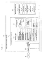
- Fig. 1 illustrates an exemplary schematic configuration of a monitoring system 1 according to Embodiment 1 of the present invention.
- the monitoring system 1 includes a remote monitoring center 15.
- the remote monitoring center 15 communicates with air-conditioning apparatuses 31-1 through 31-N installed in each of buildings 11 via a communication network 5, thereby the monitoring system 1 monitors the air-conditioning apparatuses 31-1 through 31-N of each building 11.
- the remote monitoring center 15 includes a management apparatus 61 and a server apparatus 63 and may include other devices.
- the management apparatus 61 performs failure diagnosis or the like of the air-conditioning apparatuses 31-1 through 31-N of each building 11, and the server apparatus 63 operates various servers in cooperation with the management apparatus 61.
- the building 11 may be a building, factory, or the like, for example.
- the building 11 includes the air-conditioning apparatuses 31-1 through 31-N and a controller 51, and is configured such that the air-conditioning apparatuses 31-1 through 31-N can communicate with each other via a communication line 41.
- each of the air-conditioning apparatuses 31-1 through 31-N includes a refrigerant circuit 35, and supplies conditioned air to the space or the like provided in the building 11 by using the refrigerant circuit 35.
- the air-conditioning apparatuses 31-1 through 31-N are referred to as "air-conditioning apparatuses 31" when not particularly distinguished from each other.
- the controller 51 is connected to the air-conditioning apparatuses 31 via the communication line 41.
- the controller 51 supplies various setting values, various control instructions, and the like, to the air-conditioning apparatuses 31 via the communication line 41, and thus controls the air-conditioning apparatuses 31.
- the controller 51 performs communication via the communication line 41 and the communication network 5 when communicating with the outside. For example, the controller 51 relays communication between the air-conditioning apparatuses 31 and the remote monitoring center 15.
- the air-conditioning apparatuses 31 communicate with the remote monitoring center 15 via the controller 51.
- the monitoring system 1 further includes a service center 17.
- the service center 17 provides various services related to maintenance or the like of the air-conditioning apparatuses 31, and includes a terminal 71.
- the terminal 71 communicates with the remote monitoring center 15 and the like via the communication network 5, and receives various types of information. For example, upon receiving information indicating an abnormality in the air-conditioning apparatus 31 installed in the building 11 from the remote monitoring center 15, the terminal 71 notifies a maintenance staff or the like belonging to the service center 17 of the abnormality such that the maintenance staff is sent.
- Notifying means may notify the maintenance staff of the abnormality via a monitor (not illustrated), for example.
- the notifying means is not particularly limited, and may issue a notification to a mobile phone or the like of the maintenance staff from the terminal 71, for example.
- the communication network 5 is a communication medium conforming to the Internet Protocol, for example, but is not so limited.
- the communication network 5 may be a communication network conforming to another communication protocol.
- the communication network 5 may be a communication medium for wired communication or a communication medium for wireless communication.
- Fig. 2 illustrates an exemplary configuration of the refrigerant circuit 35 according to Embodiment 1 of the present invention.
- the refrigerant circuit 35 includes a heat-source-side unit 81 and load-side units (use-side units) 82-1 through 82-N.
- the heat-source-side unit 81 is a so-called outdoor unit.
- the heat-source-side unit 81 includes, as a main circuit of the refrigerant circuit 35, a compressor 91, a four-way valve 92, a heat-source-side heat exchanger 93, an opening-degree-variable outdoor expansion device 96, and an accumulator 95, which are connected sequentially.
- the heat-source-side unit 81 includes a heat-source-side control unit 101.
- the heat-source-side control unit 101 controls the compressor 91 and the like and supplies various signals to the outside, on the basis of detection results of various sensors (described below).
- the load-side unit 82-1 is a so-called indoor unit, and includes a load-side heat exchanger (use-side heat exchanger) 97-1 and an indoor expansion device 99-1.
- the load-side unit 82-1 includes a load-side control unit 102-1 and a remote controller 103-1.
- the load-side control unit 102-1 controls the indoor expansion device 99-1 and the like and supplies various signals to the outside, on the basis of detection results of various sensors (described below) and control instructions from the remote controller 103-1.
- the load-side units 82-2 through 82-N have the same configuration as that of the load-side unit 82-1, and description thereof will not be provided.
- load-side units 82-1 through 82-N are referred to as “load-side units 82" when not particularly distinguished from each other.
- load-side heat exchangers 97-1 through 97-N are referred to as “load-side heat exchangers 97" when not particularly distinguished from each other.
- indoor expansion devices 99-1 through 99-N are referred to as “indoor expansion devices 99” when not particularly distinguished from each other.
- the load-side control units 102-1 through 102-N are referred to as “load-side control units 102" when not particularly distinguished from each other.
- the remote controllers 103-1 through 103-N are referred to as “remote controllers 103" when not particularly distinguished from each other.
- the heat-source-side unit 81 and the load-side unit 82 are connected to each other with a first connection pipe 111 and a second connection pipe 112, via a valve 121 a and a valve 121 b, respectively.
- a valve 121 a and a valve 121 b are referred to as "valves 121" when not particularly distinguished from each other.
- the refrigerant circuit 35 that circulates refrigerant through the compressor 91, the four-way valve 92, the heat-source-side heat exchanger 93, the outdoor expansion device 96, the indoor expansion device 99, the load-side heat exchanger 97, and the accumulator 95.
- the accumulator 95 accumulates excess refrigerant.
- indoor expansion device 99 corresponds to an expansion valve in the present invention.
- the heat-source-side heat exchanger 93 is provided with an outdoor fan 94 that blows air.
- the load-side heat exchangers 97-1 through 97-N are provided with indoor fans 98-1 through 98-N, respectively, that send air.
- the indoor fans 98-1 through 98-N are referred to as "indoor fans 98" when not particularly distinguished from each other.
- Each of the outdoor fan 94 and the indoor fans 98 includes a centrifugal fan, a multi-blade fan, or the like, driven by a DC motor (not illustrated), and is capable of adjusting the amount of blowing air.
- the compressor 91 is a compressor capable of changing the operating capacity.
- the compressor 91 includes a positive-displacement compressor that is driven by a motor controlled by an inverter, for example.
- the valve 121 includes a vale capable of opening and closing, such as a ball valve, an on-off valve, and an operating valve, for example.
- the four-way valve 92 switches the path through which the refrigerant flows upon switching between the heating operation and cooling operation.
- the refrigerant circuit 35 described above includes the four-way valve 92, but is not so limited.
- the refrigerant circuit 35 does not have to include the four-way valve 92 and may perform only the heating operation (including the air blowing operation).
- the refrigerant circuit 35 does not have to include the four-way valve 92, and may perform only the cooling operation.
- the refrigerant circuit 35 described above includes the accumulator 95, but is not so limited.
- the refrigerant circuit 35 does not have to include the accumulator 95.
- the number of load-side units 82 and their capacity are not particular limited.
- the following describes refrigerant circulating in the refrigerant circuit 35 and fluid with which the refrigerant exchanges heat.
- the type of the refrigerant circulating in the refrigerant circuit 35 is not particularly limited, and any refrigerant may be used.
- the refrigerant may be a natural refrigerant, such as carbon dioxide (CO 2 ) and helium, or an alternative refrigerant not containing chlorine, such as R410A, R407C, and R404A.
- the fluid with which the refrigerant exchanges heat is air, for example, but is not so limited.
- Such fluid may be water, refrigerant, brine, or the like, for example.
- a supply apparatus that supplies such fluid may be a pump or the like.
- the air-conditioning apparatus 31 is not particularly limited as long as a heat pump system is employed.
- the heat-source-side unit 81 is provided with a compressor discharge refrigerant pressure sensor 201, a compressor suction refrigerant pressure sensor 202, a liquid pipe pressure sensor 203, a compressor discharge refrigerant temperature sensor 205, a compressor suction refrigerant temperature sensor 206, an air temperature sensor 207, a heat-source-side heat exchanger liquid refrigerant temperature sensor 211, and a heat-source-side heat exchanger two-phase gas-liquid refrigerant temperature sensor 212.
- the load-side units 82-1 through 82-N are provided with load-side refrigerant liquid temperature sensors 221-1 through 221-N, inlet air temperature sensors 223-1 through 223-N, and load-side refrigerant gas temperature sensors 224-1 through 224-N, respectively.
- the compressor discharge refrigerant pressure sensor 201 is disposed at the discharge side of the compressor 91, and detects the pressure of the refrigerant discharged from the compressor 91.
- the compressor suction refrigerant pressure sensor 202 is disposed at the suction side of the compressor 91, and detects the pressure of the refrigerant to be suctioned into the compressor 91.
- the liquid pipe pressure sensor 203 is disposed between the outdoor expansion device 96 and the valve 121 b, and detects the temperature of the refrigerant flowing between the outdoor expansion device 96 and the valve 121 b.
- the compressor discharge refrigerant temperature sensor 205 is disposed at the discharge side of the compressor 91, and detects the temperature of the refrigerant discharged from the compressor 91.
- the compressor suction refrigerant temperature sensor 206 is disposed at the suction side of the compressor 91, and detects the temperature of the refrigerant to be suctioned into the compressor 91.
- the air temperature sensor 207 is disposed, for example, between the outdoor fan 94 and a housing (not illustrated) of the heat-source-side unit 81, and detects the temperature of the air around the heat-source-side unit 81 to be suctioned by the outdoor fan 94.
- the heat-source-side heat exchanger liquid refrigerant temperature sensor 211 is disposed between the heat-source-side heat exchanger 93 and the outdoor expansion device 96, and detects the temperature of the refrigerant flowing between the heat-source-side heat exchanger 93 and the outdoor expansion device 96.
- the heat-source-side heat exchanger two-phase gas-liquid refrigerant temperature sensor 212 is disposed in the heat-source-side heat exchanger 93, and detects the temperature of the refrigerant flowing through the heat-source-side heat exchanger 93.
- the detection results of the compressor discharge refrigerant pressure sensor 201, the compressor suction refrigerant pressure sensor 202, the liquid pipe pressure sensor 203, the compressor discharge refrigerant temperature sensor 205, the compressor suction refrigerant temperature sensor 206, the air temperature sensor 207, the heat-source-side heat exchanger liquid refrigerant temperature sensor 211, and the heat-source-side heat exchanger two-phase gas-liquid refrigerant temperature sensor 212 are supplied to the heat-source-side control unit 101.
- the load-side refrigerant liquid temperature sensors 221-1 through 221-N are referred to as “load-side refrigerant liquid temperature sensors 221" when not particularly distinguished from each other.
- the inlet air temperature sensors 223-1 through 223-N are referred to as “inlet air temperature sensors 223” when not particularly distinguished from each other.
- the load-side refrigerant gas temperature sensors 224-1 through 224-N are referred to as "load-side refrigerant gas temperature sensors 224" when not particularly distinguished from each other.
- the load-side refrigerant liquid temperature sensor 221 is disposed between the indoor expansion device 99 and the load-side heat exchanger 97, and detects the temperature of the refrigerant flowing between the indoor expansion device 99 and the load-side heat exchanger 97.
- the inlet air temperature sensor 223 is disposed between the indoor fan 98 and a housing (not illustrated) of the load-side unit 82, and detects the temperature of the air around the load-side unit 82 to be suctioned by the indoor fan 98.
- the load-side refrigerant gas temperature sensor 224 is disposed between the load-side heat exchanger 97 and the valve 121 a, and detects the temperature of the refrigerant flowing between the load-side heat exchanger 97 and the valve 121 a.
- the detection results of the load-side refrigerant liquid temperature sensor 221, the inlet air temperature sensor 223, and the load-side refrigerant gas temperature sensor 224 are supplied to the load-side control unit 102.
- the heat-source-side control unit 101 and the load-side control unit 102 control the flow of the refrigerant in the refrigerant circuit 35 in cooperation with each other so as to control the air-conditioning apparatus 31, and supply various signals to the controller 51.
- the controller 51 supplies the various signals supplied from the heat-source-side control unit 101 and the load-side control unit 102, to the remote monitoring center 15 via the communication network 5.
- the remote monitoring center 15 performs various calculations on the basis of the various signals supplied via the communication network 5, and remotely monitors the air-conditioning apparatus 31. For example, the remote monitoring center 15 determines whether the air-conditioning apparatus 31 is in a failed state. Further, in the case where the air-conditioning apparatus 31 is in the failed state, the remote monitoring center 15 determines the cause of the failure. The following describes the details of the remote monitoring center 15 that performs such operations, with reference to Fig. 3 .
- Fig. 3 illustrates an exemplary functional configuration of the remote monitoring center 15 according to Embodiment 1 of the present invention.
- the remote monitoring center 15 includes the management apparatus 61, the server apparatus 63, and a router apparatus 65.
- the management apparatus 61 includes a control unit 83, a communication unit 84, a storage unit 85, a display unit 87, and an operation unit 89, and performs failure diagnosis, determination of the cause of a failure, or the like of the air-conditioning apparatus 31.
- the control unit 83 includes a capacity calculation unit 301, a failure cause diagnosis unit 303, and a failure prediction unit 105.
- the control unit 83 includes a microprocessor or the like as a main component, for example, but is not so limited.
- the capacity calculation unit 301 includes a circulation amount calculation unit 311, a subcooling degree calculation unit 312, a superheat degree calculation unit 313, a discharge superheat degree calculation unit 314, and a refrigeration capacity calculation unit 315, and calculates the refrigeration capacity of the air-conditioning apparatus 31.
- the circulation amount calculation unit 311 calculates the circulation amount of the refrigerant flowing in the air-conditioning apparatus 31, as will be described in detail below with reference to Fig. 6 .
- the subcooling degree calculation unit 312 calculates a heat-source-side heat exchanger subcooling degree SC in the heat-source-side heat exchanger 93, as will be described in detail below with reference to Fig. 6 .
- the superheat degree calculation unit 313 calculates a load-side heat exchanger superheat degree SH in the load-side heat exchanger 97, as will be described in detail below with reference to Fig. 6 .
- the discharge superheat degree calculation unit 314 calculates a compressor discharge superheat degree TdSH in the compressor 91, as will be described in detail below with reference to Fig. 6 .
- the refrigeration capacity calculation unit 315 estimates the refrigeration capacity in the load-side heat exchanger 97, as will be described in detail below with reference to Fig. 6 .
- the failure cause diagnosis unit 303 performs failure diagnosis, determination of the cause of a failure, or the like of the air-conditioning apparatus 31, on the basis of the calculation result of the capacity calculation unit 301 and the detection results from a past operation database, as will be described in detail below with reference to Figs. 4 through 8 .
- the failure prediction unit 305 performs failure prediction on the basis of the calculation result of the capacity calculation unit 301, as will be described in detail below with reference to Fig. 9 .
- the communication unit 84 is an interface for communication between the control unit 83 and external apparatuses.
- the communication unit 84 converts various signals supplied from the control unit 83 into data of a predetermined format, and supplies the data to the server apparatus 63 or the router apparatus 65.
- the communication unit 84 converts various signals supplied from the server apparatus 63 or the router apparatus 65 into data of a predetermined format, and supplies the data to the control unit 83.
- the storage unit 85 includes, for example, a past operation database 321 and a failure diagnosis database 322.
- the past operation database 321 stores past operation data of the air-conditioning apparatus 31 in chronological order.
- the failure diagnosis database 322 stores past operation data of the air-conditioning apparatus 31 and a capacity change rate calculated from the operation data.
- the display unit 87 displays the various calculation results of the control unit 83, the detection results from the past operation database 321, and the detection results from the failure diagnosis database 322 in a predetermined format.
- the operation unit 89 is an input interface between the user and the management apparatus 62.
- the operation unit 89 receives various operations from the user, converts the results into a control instruction, and supplies the control code to the control unit 83.
- the server apparatus 63 includes, for example, a database server 411, a file server 413, a print server 415, a web server 417, and a mail server 419, and has a functional configuration for providing some services, that is, processing in response to a demand, that is, a request from the management apparatus 61.
- the database server 411 includes various databases. Thus, in response to a request from the management apparatus 61, the database server 411 performs search, update, or the like of the various databases, and returns the result to the management apparatus 61.
- the file server 413 provides various stored files, that is, data.
- the print server 415 provides a print job for a printer.
- the web server 417 provides data such as HTML (HyperText Markup Language) files or image files for Web pages.
- the mail server 419 controls delivery of e-mail.
- server apparatus 63 may be implemented as hardware or may be virtually implemented as software. That is, the various functions provided by the server apparatus 63 are not subject to any physical constraints.
- failure diagnosis or the like may be performed via a mobile terminal or the like.
- failure diagnosis or the like may be performed by the server apparatus 63 in cooperation with the management apparatus 61.
- the router apparatus 65 is an apparatus that connects two or more different networks. For example, the router apparatus 65 performs path control on the basis of IP address, and relays communication between the management apparatus 61 and the controller 51.
- Fig. 4 illustrates changes in refrigeration capacity with time according to Embodiment 1 of the present invention.
- changes in refrigeration capacity with time are illustrated for each pattern.
- Pattern #1 and Pattern #2 are patterns in which operation data of the air-conditioning apparatus 31 for a predetermined operation data storage period after an abnormality of the air-conditioning apparatus 31 is detected by the remote monitoring center 15 is stored.
- Pattern #3 and Pattern #4 are patterns in which operation data of the air-conditioning apparatus 31 for an operation data storage period from a time point before the abnormality of the air-conditioning apparatus 31 is detected by the remote monitoring center 15 to a predetermined time point is stored. That is, the operation data storage period of Pattern #1 and Pattern #2 and the data storage period of Patten #3 and pattern #4 differ in length of the storage period.
- the refrigeration capacity is normal until halfway, but an abnormality is detected when the refrigeration capacity becomes less than or equal to a refrigeration capacity abnormality determination value for determining whether the refrigeration capacity is abnormal.
- the operation data storage period of the air-conditioning apparatus 31 is set to the period from a time point when the abnormality is detected to a time point when the refrigeration capacity reaches an abnormal stop state.
- the refrigeration capacity gradually decreases, and an abnormality is detected when the refrigeration capacity becomes less than or equal to the refrigeration capacity abnormality determination value.
- the operation data storage period of the air-conditioning apparatus 31 is set to the period from a time point when the abnormality is detected to a time point when the refrigeration capacity reaches the abnormal stop state.
- the refrigeration capacity is normal until halfway, but an abnormality is detected when the refrigeration capacity becomes less than or equal to the refrigeration capacity abnormality determination value.
- the operation data storage period of the air-conditioning apparatus 31 is set to the period from a time point before detection of the abnormality to a time point when the refrigeration capacity reaches the abnormal stop state.
- the refrigeration capacity gradually decreases, and an abnormality is detected when the refrigeration capacity becomes less than or equal to the refrigeration capacity abnormality determination value.
- the operation data storage period of the air-conditioning apparatus 31 is set to the period from a time point before detection of the abnormality to a time point when the refrigeration capacity reaches the abnormal stop state.
- Pattern #1 and Pattern #2 only the operation data after detection of the abnormality is stored.
- Pattern #3 and Pattern #4 the operation data before detection of the abnormality is also stored. Accordingly, in Pattern #1 and Pattern #2, data on changes in refrigeration capacity during the period before the failing into the abnormal state is not stored.
- Pattern #3 and Pattern #4 data on changes in refrigeration capacity during the period before the failing into the abnormal state is stored.
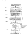
- Fig. 5 is a flowchart illustrating a failure diagnosis process according to Embodiment 1 of the present invention.
- the failure cause diagnosis unit 303 initializes the abnormality count.
- the abnormality count is a parameter that counts the number of times that the refrigeration capacity becomes less than or equal to the refrigeration capacity abnormality determination value (described below). As will be described, a determination is made on whether the obtained refrigeration capacity is temporal, using the abnormality count as the parameter.
- the failure cause diagnosis unit 303 determines whether an operation data acquisition period has arrived. If the failure cause diagnosis unit 303 determines that an operation data acquisition period has arrived, the process proceeds to step S13. On the other hand, if the failure cause diagnosis unit 303 determines that an operation data acquisition period has not been arrived, the process returns to step S12.
- the operation data acquisition period is an interval at which the failure cause diagnosis unit 303, that is, the remote monitoring center 15 acquires operation data of the air-conditioning apparatus 31 installed in each building 11. For example, if the operation data acquisition period is set to one hour, it is possible to perform failure diagnosis on the basis of changes in the operation data of each hour.
- the operation data acquisition period is set to one day, it is possible to perform failure diagnosis on the basis of changes in the operation data of each day. That is, it is possible to change the number of times the failure diagnosis is performed in accordance with the operation data acquisition period.
- the failure cause diagnosis unit 303 acquires operation data.
- the operation data refers to various parameters used for calculation in a refrigeration capacity calculation process (described below). For example, when setting a reference operating state, the failure cause diagnosis unit 303 acquires an operating frequency F0 of the compressor 91, a speed fano0 of the outdoor fan 94, and a valve opening degree LEV0 of the indoor expansion device 99. Further, for example, when detecting the pressure of the compressor 91, the failure cause diagnosis unit 303 acquires a compressor discharge pressure Pd and a compressor suction pressure Ps.
- the failure cause diagnosis unit 303 acquires a heat-source-side heat exchanger two-phase temperature T212 and a heat-source-side heat exchanger subcooled liquid temperature T211. Further, for example, when calculating the load-side heat exchanger superheat degree SH, the failure cause diagnosis unit 303 acquires a load-side heat exchanger superheated gas temperature T224 and a load-side inlet air temperature T223. Further, for example, when calculating the compressor discharge superheat degree TdSH, the failure cause diagnosis unit 303 acquires a discharge temperature T205 and the heat-source-side heat exchanger two-phase temperature T212.
- Fig. 6 is a flowchart illustrating the refrigeration capacity calculation process according to Embodiment 1 of the present invention.
- the capacity calculation unit 301 sets the reference operating state. More specifically, the capacity calculation unit 301 sets the operating frequency F0 of the compressor 91, the speed fano0 of the outdoor fan 94, and the valve opening degree LEV0 of the indoor expansion device 99, for the air-conditioning apparatus 31.
- the air-conditioning apparatus 31 operates and enters a stable state.
- the capacity calculation unit 301 detects a pressure of the compressor 91. More specifically, the capacity calculation unit 301 detects the compressor discharge pressure Pd using the compressor discharge refrigerant pressure sensor 201, and detects the compressor suction pressure Ps using the compressor suction refrigerant pressure sensor 202.
- the capacity calculation unit 301 calculates a refrigerant circulation amount Gr. More specifically, the capacity calculation unit 301 causes the circulation amount calculation unit 311 to calculate the refrigerant circulation amount Gr on the basis of the operating frequency F0, the compressor discharge pressure Pd, and the compressor suction pressure Ps of the compressor 91, using the following Formula (1).
- Gr f F ⁇ 0 , Pd , Ps
- Gr f(F0, Pd, Ps) may be implemented in a manner such that a correspondence table for each parameter is prepared in advance and Gr is calculated by referring to the correspondence table.
- a table may be defined in advance such that when F0, Pd, and Ps are determined, the corresponding refrigerant circulation amount Gr is determined.
- the capacity calculation unit 301 detects calculation parameters using the various sensors. More specifically, the capacity calculation unit 301 detects the discharge temperature T205 using the compressor discharge refrigerant temperature sensor 205. Further, the capacity calculation unit 301 detects the heat-source-side heat exchanger two-phase temperature T212 using the heat-source-side heat exchanger two-phase gas-liquid refrigerant temperature sensor 212. Further, the capacity calculation unit 301 detects the heat-source-side heat exchanger subcooled liquid temperature T211 using the heat-source-side heat exchanger liquid refrigerant temperature sensor 211. Further, the capacity calculation unit 301 detects a load-side heat exchanger liquid pipe temperature T221 using the load-side refrigerant liquid temperature sensor 221.
- the capacity calculation unit 301 detects the load-side heat exchanger superheated gas temperature T224 using the load-side refrigerant gas temperature sensor 224. Further, the capacity calculation unit 301 detects the load-side inlet air temperature T223 using the inlet air temperature sensor 223.
- the capacity calculation unit 301 issues, to the superheat degree calculation unit 313, an instruction for calculating the load-side heat exchanger superheat degree SH on the basis of the load-side heat exchanger superheated gas temperature T224 and the load-side inlet air temperature T223, using the following Formula (3).
- the superheat degree calculation unit 313 calculates the load-side heat exchanger superheat degree SH, using the following Formula (3).
- Formula 3) SH T ⁇ 224 - T ⁇ 223
- the capacity calculation unit 301 issues, to the discharge superheat degree calculation unit 314, an instruction for calculating the compressor discharge superheat degree TdSH on the basis of the discharge temperature T205 and the heat-source-side heat exchanger two-phase temperature T212, using the following Formula (4).
- the capacity calculation unit 301 issues, to the refrigeration capacity calculation unit 315, an instruction for calculating a refrigerant enthalpy Hout at the outlet side of the load-side heat exchanger 97 on the basis of the compressor suction pressure Ps and the load-side heat exchanger superheated gas temperature T224, using the following Formula (6).
- Hein also indicates the degree of subcooling of the liquid refrigerant flowing out of the heat-source-side heat exchanger 93. Further, Hout also indicates the degree of superheat of the gas refrigerant flowing out of the load-side heat exchanger 97.
- Formulas (5) and (6) are functions defined in advance on the basis of the type of the refrigerant circulating in the refrigerant circuit.
- the remote monitoring center 15 includes the capacity calculation unit 301, and the capacity calculation unit 301 of the remote monitoring center 15 calculates the refrigeration capacity.
- the disclosure is not limited thereto.
- the air-conditioning apparatus 31 may include the capacity calculation unit 301.
- the controller 51 may include the capacity calculation unit 301.
- the failure cause diagnosis unit 303 acquires the refrigeration capacity abnormality determination value.
- the refrigeration capacity abnormality determination value is set to a refrigeration capacity that is abnormal. For example, in the case where an air-conditioning system operates with the refrigeration capacity in a range between 1,000 kw and 600 kw, the refrigeration capacity is abnormal when the refrigeration capacity is less than 600 kw. In this case, the refrigeration capacity abnormality determination value is set to 600 kw.
- the failure cause diagnosis unit 303 acquires an abnormality count determination value.
- the abnormality count determination value is used for determining whether the refrigeration capacity is abnormal temporarily or constantly. With this process, it is possible to ignore the value at the time when the refrigeration capacity is temporarily reduced due to some effect, and thus to improve the accuracy of failure cause diagnosis. That is, it is possible to exclude the case in which the refrigeration capacity is reduced due to some noise or the like.
- abnormality count determination value is, for example, but not limited to, three.
- the failure cause diagnosis unit 303 determines whether the refrigeration capacity is less than or equal to the refrigeration capacity abnormality determination value. If the failure cause diagnosis unit 303 determines that the refrigeration capacity is less than or equal to the refrigeration capacity abnormality determination value, the process proceeds to step S18. On the other hand, if the failure cause diagnosis unit 303 determines that the refrigeration capacity is greater than the refrigeration capacity abnormality determination value, the process returns to step S12.
- the failure cause diagnosis unit 303 determines whether the abnormality count has reached the abnormality count determination value. If the failure cause diagnosis unit 303 determines that the abnormality count has reached the abnormality count determination value, the process proceeds to step S20. On the other hand, if the failure cause diagnosis unit 303 determines that the abnormality count has not reached the abnormality count determination value, the process proceeds to step S19.
- the failure cause diagnosis unit 303 increments the abnormality count. For example, the failure cause diagnosis unit 303 adds 1 to the abnormality count, that is, increments the abnormality count by 1.
- the failure cause diagnosis unit 303 acquires past operation data for a predetermined period from the past operation database 321. For example, the failure cause diagnosis unit 303 acquires operation data for the last month from the past operation database 321.
- Fig. 7 is a flowchart illustrating the capacity variation calculation process according to Embodiment 1 of the present invention.
- the failure cause diagnosis unit 303 initializes an abnormality determination flag.
- the failure cause diagnosis unit 303 calculates the capacity change rate with respect to time at predetermined time intervals.
- the predetermined time intervals are a plurality of small time segments obtained by dividing the operation data storage period on the time axis, as will be described in detail below with reference to Fig. 8 .
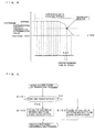
- Fig. 8 illustrates the predetermined time intervals for calculation of the capacity change rate with respect to time according to Embodiment 1 of the present invention.
- the operation data storage period is divided into a plurality of predetermined time intervals.
- the failure cause diagnosis unit 303 calculates the capacity change rate with respect to time at the predetermined time intervals.
- the capacity change rate of a time interval named A is a
- the capacity change rate of a time interval named B is b
- the capacity change rate of a time interval named C is c.
- the failure cause diagnosis unit 303 acquires a predetermined refrigeration capacity change rate abnormality determination value.
- the refrigeration capacity change rate abnormality determination value is for determining whether the capacity change rate with respect to time is in an allowable range, as will be described in detail below.
- the failure cause diagnosis unit 303 determines whether there is a capacity change rate greater than the refrigeration capacity change rate abnormality determination value. If the failure cause diagnosis unit 303 determines that there is a capacity change rate greater than the refrigeration capacity change rate abnormality determination value, the process proceeds to step S85. On the other hand, if the failure cause diagnosis unit 303 determines that there is no capacity change rate greater than the refrigeration capacity change rate abnormality determination value, the process proceeds to step S87.
- the capacity change rate is the change rate of the refrigeration capacity with respect to time. That is, the capacity change rate represents the inclination of the characteristic graph of the refrigeration capacity. Accordingly, comparing the capacity change rate with the refrigeration capacity change rate abnormality determination value corresponds to determining the degree of the inclination of the characteristic graph of the refrigeration capacity. If the inclination of the characteristic graph of the refrigeration capacity is steep, it indicates that the refrigeration capacity decreases sharply. That is, a determination on whether the air-conditioning apparatus 31 is in the abnormal state may be made on the basis of the degree of reduction in the refrigeration capacity.
- processing at this stage is processing to be performed when the refrigeration capacity is already less than or equal to the refrigeration capacity abnormality determination value (see Steps S11 through S20). That is, the refrigeration capacity has decreced for some reason.
- the air-conditioning apparatus 31 is determined to be in the abnormal state, not due to aging degradation, but due to some other factors.
- the air-conditioning apparatus 31 may be determined to be in the abnormal state on the basis of the refrigeration capacity change rate abnormality determination value in the time interval B prior to the detection of the abnormality.
- the failure cause diagnosis unit 303 sets the abnormality determination flag to 1.
- the failure cause diagnosis unit 303 sets the aging degradation flag to 0.
- the failure cause diagnosis unit 303 sets the aging degradation flag to 1.
- the failure cause diagnosis unit 303 executes a failure cause determination process.
- the failure cause determination process will be described in detail below with reference to Fig. 9 .
- Fig. 9 is a flowchart illustrating the failure cause determination process according to Embodiment 1 of the present invention.
- the failure cause diagnosis unit 303 determines whether the aging degradation flag is 1. If the failure cause diagnosis unit 303 determines that the aging degradation flag is 1, the process proceeds to step S102. On the other hand, if the failure cause diagnosis unit 303 determines that the aging degradation flag is not 1, the process proceeds to step S103.
- the failure cause diagnosis unit 303 determines that the cause of the failure is aging degradation. That is, the failure cause diagnosis unit 303 determines that the reduction in refrigeration capacity is due to aging degradation.
- the failure cause diagnosis unit 303 determines that the cause of the failure is not aging degradation. That is, the failure cause diagnosis unit 303 determines that the reduction in refrigeration capacity is not due to aging degradation but is due to some external factors. In this case, a notification of the abnormality needs to be issued immediately, and therefore an operation for issuing a notification of the abnormality will be performed in the subsequent process, for example.
- the failure cause diagnosis unit 303 determines whether the abnormality determination flag is 1. If the failure cause diagnosis unit 303 determines that the abnormality determination flag is 1, the process proceeds to step S23. On the other hand, if the failure cause diagnosis unit 303 determines that the abnormality determination flag is not 1, the process returns to step S12.
- the failure cause diagnosis unit 303 issues a notification of the abnormality.
- the failure cause diagnosis unit 303 may issue a notification of the abnormality to the manager (not illustrated) of the building 11. Further, for example, the failure cause diagnosis unit 303 may issue a notification of the abnormality to the terminal 71 of the service center. Further, for example, the failure cause diagnosis unit 303 may issue a notification of the abnormality to the display unit 87.
- a notification of the abnormality may be issued by, for example, transmitting e-mail or the like, but the disclosure is not limited thereto.
- a notification of the abnormality may be issued by sound. Further, a notification of the abnormality may be issued by changing the intervals at which a lamp or the like (not illustrated) blinks.
- the failure cause diagnosis unit 303 acquires operation data for the predetermined storage period. More specifically, the failure cause diagnosis unit 303 acquires operation data for 10 minutes, for example.
- predetermined period described above is for illustrative purposes only, and the disclosure is not limited thereto.
- the failure cause diagnosis unit 303 stores the operation data and the result of the capacity variation calculation process obtained from the operation data in the failure diagnosis database 322, and the process ends.
- the failure cause diagnosis unit 303 stores the operation data and the capacity change rate indicated in the result of the capacity variation calculation process obtained from the operation data as a pair in the failure diagnosis database 322, and the process ends.
- Fig. 10 is a flowchart illustrating a failure prediction process according to Embodiment 1 of the present invention.
- the failure prediction unit 305 initializes the abnormality determination flag.
- the failure prediction unit 305 calculates the capacity change rate with respect to time at predetermined time intervals.
- the failure prediction unit 305 calculates the change rate of the capacity change rate with respect to time at predetermined time intervals. That is, the failure prediction unit 305 calculates the degree of change in the capacity change rate. By calculating the degree of change in the capacity change rate, it is possible to determine whether the capacity change rate will increase or decrease. If the degree of change in the capacity change rate will increase further, the capacity change rate will continue to exhibit a steep slope over time. Therefore, in this case, a prediction may be made that a failure is likely to occur in the near future. On the other hand, if the degree of change in the capacity change rate will not increase further, the capacity change rate will not continue to exhibit a steep slope over time. Therefore, in this case, a prediction may be made that a failure is not likely to occur in the near future.
- the failure prediction unit 305 acquires a predetermined failure prediction determination value.
- the failure prediction unit 305 determines whether there is a change rate of the capacity change rate greater than the failure prediction determination value. If the failure prediction unit 305 determines that there is a change rate of the capacity change rate greater than the failure prediction determination value, the process proceeds to step S116. On the other hand, if the failure prediction unit 305 determines that there is no change rate of the capacity change rate greater than the failure prediction determination value, the process ends.
- the failure prediction unit 305 sets the abnormality determination flag to 1, and the process ends.
- steps S111 through step S116 may be incorporated in place of the capacity variation calculation process of step S21 of Fig. 5 .
- the failure prediction process is incorporated into the failure diagnosis process.
- operation data on at least one air-conditioning apparatus 31 is exchanged between the at least one air-conditioning apparatus 31 and the management apparatus 61 that manages the at least one air-conditioning apparatus 31 in the monitoring system 1.
- the management apparatus 61 includes the failure cause diagnosis unit 303 that diagnoses the cause of a failure of the at least one air-conditioning apparatus 31 on the basis of the operation data.
- a refrigeration capacity abnormality determination value for determining whether a refrigeration capacity calculated from the operation data on the air-conditioning apparatus 31 is abnormal and a refrigeration capacity change rate abnormality determination value for determining whether a refrigeration capacity change rate of the refrigeration capacity with respect to time is abnormal are set in the failure cause diagnosis unit 303.
- the failure cause diagnosis unit 303 determines that the air-conditioning apparatus 31 is in a failed state if the refrigeration capacity is less than or equal to the refrigeration capacity abnormality determination value.
- the failure cause diagnosis unit 303 determines that the cause of the failure of the air-conditioning apparatus 31 is not aging degradation if the air-conditioning apparatus 31 is in the failed state and if the refrigeration capacity change rate of the refrigeration capacity is greater than the refrigeration capacity change rate abnormality determination value, and determines that the cause of the failure of the air-conditioning apparatus 31 is aging degradation if the air-conditioning apparatus 31 is in the failed state and if the refrigeration capacity change rate of the refrigeration capacity is not greater than the refrigeration capacity change rate abnormality determination value.
- a failure of the air-conditioning apparatus 31 will be a factor that leads to a failure of the data center. Even in such a case, since a quick response is possible, the assets of the data center can be protected.
- the maintenance staff who rushed to the site can perform appropriate maintenance activities. This enables both a reduction in time and a quick recovery.
- monitoring system 5 communication network 11 building 15 remote monitoring center 17 service center 31, 31-1 - 31-N air-conditioning apparatus 35 refrigerant circuit 41 communication line 51 controller 61 management apparatus 63 server apparatus 65 router apparatus 71 terminal 81 heat-source-side unit 82, 82-1 - 82-N load-side unit 83 control unit 84 communication unit 85 storage unit 87 display unit 89 operation unit 91 compressor 92 four-way valve 93 heat-source-side heat exchanger 94 outdoor fan 95 accumulator 96 outdoor expansion device 97, 97-1 - 97-N load-side heat exchanger98, 98-1 - 98-N indoor fan 99, 99-1 - 99-N indoor expansion device 101 heat-source-side control unit 102, 102-1 - 102-N load-side control unit 103, 103-1, 103-N remote controller 111 first connection pipe 112 second connection pipe 121, 121 a, 121 b valve 201 compressor discharge refrigerant pressure sensor 202 compressor suction refrigerant pressure sensor 203 liquid pipe
Landscapes
- Engineering & Computer Science (AREA)
- General Engineering & Computer Science (AREA)
- Combustion & Propulsion (AREA)
- Mechanical Engineering (AREA)
- Chemical & Material Sciences (AREA)
- Physics & Mathematics (AREA)
- Mathematical Physics (AREA)
- Fuzzy Systems (AREA)
- Signal Processing (AREA)
- Human Computer Interaction (AREA)
- General Physics & Mathematics (AREA)
- Automation & Control Theory (AREA)
- Health & Medical Sciences (AREA)
- Biomedical Technology (AREA)
- Quality & Reliability (AREA)
- Air Conditioning Control Device (AREA)
Applications Claiming Priority (1)
| Application Number | Priority Date | Filing Date | Title |
|---|---|---|---|
| PCT/JP2012/077553 WO2014064792A1 (ja) | 2012-10-25 | 2012-10-25 | 監視システム |
Publications (2)
| Publication Number | Publication Date |
|---|---|
| EP2913601A1 true EP2913601A1 (de) | 2015-09-02 |
| EP2913601A4 EP2913601A4 (de) | 2016-07-06 |
Family
ID=50544190
Family Applications (1)
| Application Number | Title | Priority Date | Filing Date |
|---|---|---|---|
| EP12887248.8A Withdrawn EP2913601A4 (de) | 2012-10-25 | 2012-10-25 | Überwachungssystem |
Country Status (4)
| Country | Link |
|---|---|
| US (1) | US20150184880A1 (de) |
| EP (1) | EP2913601A4 (de) |
| JP (1) | JPWO2014064792A1 (de) |
| WO (1) | WO2014064792A1 (de) |
Cited By (2)
| Publication number | Priority date | Publication date | Assignee | Title |
|---|---|---|---|---|
| EP3531036A4 (de) * | 2016-11-21 | 2019-10-30 | Mitsubishi Electric Corporation | Vorrichtung zur diagnose einer verschlechterung, verfahren zur diagnose einer verschlechterung und programm zur diagnose einer verschlechterung |
| EP3704421A4 (de) * | 2017-11-01 | 2021-07-28 | Honeywell International Inc. | Bestimmung einer ursache für einen fehler in einem hlk-system |
Families Citing this family (33)
| Publication number | Priority date | Publication date | Assignee | Title |
|---|---|---|---|---|
| US10486499B2 (en) * | 2013-07-18 | 2019-11-26 | Hangzhou Sanhua Research Institute Co., Ltd. | Method for controlling vehicle air-conditioning system, and vehicle air-conditioning system |
| US10190795B2 (en) * | 2013-09-10 | 2019-01-29 | Hitachi-Johnson Controls Air Conditioning, Inc. | Air conditioner diagnostic system, air conditioner and mobile communication terminal |
| KR102343081B1 (ko) * | 2015-02-25 | 2021-12-24 | 삼성전자주식회사 | 공조 장치 및 상기 공조 장치의 제어 방법 |
| EP3290816B1 (de) * | 2015-04-28 | 2024-01-31 | Mitsubishi Electric Corporation | Überwachungsvorrichtung und verfahren für eine klimaanlage |
| CN106895546B (zh) | 2015-12-18 | 2020-09-01 | 松下知识产权经营株式会社 | 空气调节机的控制方法、终端装置以及运转控制系统 |
| CN106895544A (zh) * | 2015-12-21 | 2017-06-27 | 北京奇虎科技有限公司 | 基于空气净化设备的净化处理方法及空气净化设备 |
| CN109219552B (zh) * | 2016-06-10 | 2021-04-13 | 三菱电机株式会社 | 车用空调装置及车用空调装置的异常检测系统 |
| KR102571211B1 (ko) * | 2017-01-12 | 2023-08-24 | 엘지전자 주식회사 | 공기조화기 시스템 및 그 제어방법 |
| KR102560458B1 (ko) * | 2017-02-03 | 2023-07-26 | 엘지전자 주식회사 | 공기조화기 시스템 및 그 제어방법 |
| KR102364621B1 (ko) * | 2017-04-04 | 2022-02-17 | 엘지전자 주식회사 | 공기조화기 시스템 및 그 제어방법 |
| JP6951278B2 (ja) * | 2018-03-16 | 2021-10-20 | 日立グローバルライフソリューションズ株式会社 | サーバ、および、機器システム |
| ES2918206T3 (es) * | 2018-05-14 | 2022-07-14 | Mitsubishi Electric Corp | Sistema de diagnóstico de averías |
| CN110701727B (zh) * | 2018-07-09 | 2023-03-17 | 开利公司 | 用于检测hvac系统中故障的方法和系统以及存储器 |
| CN109579226B (zh) * | 2018-09-30 | 2021-07-20 | 广东美的制冷设备有限公司 | 空调的运行能力检测方法及系统 |
| JP6990201B2 (ja) * | 2019-01-29 | 2022-01-12 | パナソニックホームズ株式会社 | 建物の空調方法及び建物の空調装置 |
| JP7244744B2 (ja) | 2019-02-13 | 2023-03-23 | ダイキン工業株式会社 | 機器管理システム |
| US20220055442A1 (en) * | 2019-05-10 | 2022-02-24 | Carrier Corporation | Online capacity estimation of a regrigeration unit |
| JPWO2020245933A1 (ja) * | 2019-06-05 | 2021-11-11 | 三菱電機株式会社 | 空調冷熱機器管理装置 |
| CN110513825B (zh) * | 2019-08-15 | 2021-11-02 | 海信(广东)空调有限公司 | 一种冷媒泄漏检测与控制方法及系统 |
| CN111706499B (zh) * | 2020-06-09 | 2022-03-01 | 成都数之联科技有限公司 | 一种真空泵的预测维护系统及方法及真空泵自动采购系统 |
| JP7612357B2 (ja) * | 2020-08-27 | 2025-01-14 | 株式会社東芝 | 特定装置、及び特定方法 |
| CN112084096B (zh) * | 2020-09-22 | 2022-10-18 | 科华数据股份有限公司 | 冷通道密闭管理方法、装置及终端设备 |
| US12105581B2 (en) | 2020-10-07 | 2024-10-01 | Mitsubishi Electric Corporation | Failure symptom detection system, failure symptom detection method, and recording medium |
| CN112947136A (zh) * | 2021-01-16 | 2021-06-11 | 河南检亿科技有限公司 | 一种钢衬储罐老化度的智能监测装置及监测流程与方法 |
| WO2022162728A1 (ja) * | 2021-01-26 | 2022-08-04 | 三菱電機株式会社 | 遠隔監視システムおよび遠隔監視方法 |
| CN113217365B (zh) * | 2021-03-31 | 2022-11-11 | 内蒙古电力(集团)有限责任公司内蒙古电力科学研究院分公司 | 一种脱硫设施循环浆液泵状态监测方法、系统及设备 |
| JP7708598B2 (ja) * | 2021-07-07 | 2025-07-15 | アズビル株式会社 | 調熱監視装置、調熱監視プログラム、及び、調熱監視方法 |
| WO2023135785A1 (ja) * | 2022-01-17 | 2023-07-20 | 三菱電機株式会社 | 冷媒漏洩監視システムおよび冷媒漏洩監視方法 |
| JP7686141B2 (ja) * | 2022-03-08 | 2025-05-30 | 三菱電機株式会社 | 部品診断装置、部品診断システム、空気調和機の部品診断方法、部品在庫管理システム、および部品在庫管理方法 |
| CN115111706B (zh) * | 2022-06-23 | 2024-05-24 | 北京小米移动软件有限公司 | 空调缺氟检测方法、装置、介质及芯片 |
| CN115523592B (zh) * | 2022-08-18 | 2025-09-16 | 青岛海尔空调器有限总公司 | 用于空调器控制的方法及装置、空调器、存储介质 |
| CN120576443B (zh) * | 2025-06-03 | 2025-10-31 | 瑞枫盛达(北京)科技有限公司 | 一种制氧增压空调制冷一体主机的多参数实时监测系统 |
| CN120313188A (zh) * | 2025-06-16 | 2025-07-15 | 成都明日蔚蓝科技有限公司 | 一种空调设备状态监控系统及方法 |
Family Cites Families (12)
| Publication number | Priority date | Publication date | Assignee | Title |
|---|---|---|---|---|
| JP2004092976A (ja) | 2002-08-30 | 2004-03-25 | Daikin Ind Ltd | 故障診断装置および空気調和機 |
| JP4281334B2 (ja) | 2002-11-20 | 2009-06-17 | ダイキン工業株式会社 | 異常診断システム |
| JP4396286B2 (ja) | 2004-01-21 | 2010-01-13 | 三菱電機株式会社 | 機器診断装置および機器監視システム |
| US7275377B2 (en) * | 2004-08-11 | 2007-10-02 | Lawrence Kates | Method and apparatus for monitoring refrigerant-cycle systems |
| US7987679B2 (en) * | 2005-02-24 | 2011-08-02 | Mitsubishi Denki Kabushiki Kaisha | Air conditioning apparatus |
| JP4290705B2 (ja) * | 2006-03-07 | 2009-07-08 | 株式会社Nttファシリティーズ | 空気調和機の診断方法及び診断システム |
| JP4888291B2 (ja) * | 2007-09-07 | 2012-02-29 | パナソニック株式会社 | 便座装置 |
| US8019567B2 (en) * | 2007-09-17 | 2011-09-13 | Ecofactor, Inc. | System and method for evaluating changes in the efficiency of an HVAC system |
| JP4930430B2 (ja) * | 2008-03-28 | 2012-05-16 | ダイキン工業株式会社 | 冷凍装置用の電力供給装置 |
| JP2009002651A (ja) * | 2008-10-06 | 2009-01-08 | Daikin Ind Ltd | 異常診断システム |
| JP2010127568A (ja) * | 2008-11-28 | 2010-06-10 | Mitsubishi Electric Corp | 異常検出装置およびそれを備えた冷凍サイクル装置 |
| JP5289109B2 (ja) * | 2009-03-09 | 2013-09-11 | 三菱電機株式会社 | 空気調和装置 |
-
2012
- 2012-10-25 US US14/421,551 patent/US20150184880A1/en not_active Abandoned
- 2012-10-25 JP JP2014543068A patent/JPWO2014064792A1/ja active Pending
- 2012-10-25 EP EP12887248.8A patent/EP2913601A4/de not_active Withdrawn
- 2012-10-25 WO PCT/JP2012/077553 patent/WO2014064792A1/ja not_active Ceased
Cited By (2)
| Publication number | Priority date | Publication date | Assignee | Title |
|---|---|---|---|---|
| EP3531036A4 (de) * | 2016-11-21 | 2019-10-30 | Mitsubishi Electric Corporation | Vorrichtung zur diagnose einer verschlechterung, verfahren zur diagnose einer verschlechterung und programm zur diagnose einer verschlechterung |
| EP3704421A4 (de) * | 2017-11-01 | 2021-07-28 | Honeywell International Inc. | Bestimmung einer ursache für einen fehler in einem hlk-system |
Also Published As
| Publication number | Publication date |
|---|---|
| US20150184880A1 (en) | 2015-07-02 |
| WO2014064792A1 (ja) | 2014-05-01 |
| JPWO2014064792A1 (ja) | 2016-09-05 |
| EP2913601A4 (de) | 2016-07-06 |
Similar Documents
| Publication | Publication Date | Title |
|---|---|---|
| US20150184880A1 (en) | Monitoring system | |
| EP3607251B1 (de) | Klimaanlagensystem und steuerverfahren dafür | |
| US20180202681A1 (en) | Air-conditioner system and control method | |
| CN113455014B (zh) | 设备管理系统 | |
| US20080234869A1 (en) | Remote Performance Monitor and Remote Performance Monitoring Method | |
| CN110094842A (zh) | 空调运行状态监测方法 | |
| EP3795915B1 (de) | Diagnosesystem für fehlfunktion | |
| JP2010112696A (ja) | 空気調和装置の遠隔管理システムおよび遠隔管理方法 | |
| JP2019143817A (ja) | 一体型空気調和装置の管理装置および管理プログラム | |
| JP2013145078A (ja) | 冷凍機管理システム | |
| JP7262458B2 (ja) | 機器管理システム | |
| KR20180112585A (ko) | 공기조화기 시스템 및 그 제어방법 | |
| JP4479565B2 (ja) | 異常検知システム | |
| KR102521851B1 (ko) | 칠러 시스템 | |
| JP2006275303A (ja) | 異常検知システム | |
| JP2005309724A (ja) | 異常診断システム及び異常診断方法 | |
| EP3974929B1 (de) | Geräteverwaltungssystem | |
| JP2006266609A (ja) | 空調機の異常診断システム | |
| EP4400778A1 (de) | Anomaliediagnosesystem, klimaanlage und klimaanlagensystem | |
| KR20040033357A (ko) | 공기조화기 | |
| KR20180097041A (ko) | 칠러 | |
| KR20180107662A (ko) | 냉각 시스템 | |
| WO2025197752A1 (ja) | 状態判定装置、状態判定方法、故障推定装置、故障推定方法、空気調和システム及び空気調和機 | |
| JPH03199874A (ja) | 冷凍装置の不具合予知方式 | |
| KR20170025180A (ko) | 공기 조화기 |
Legal Events
| Date | Code | Title | Description |
|---|---|---|---|
| PUAI | Public reference made under article 153(3) epc to a published international application that has entered the european phase |
Free format text: ORIGINAL CODE: 0009012 |
|
| 17P | Request for examination filed |
Effective date: 20150306 |
|
| AK | Designated contracting states |
Kind code of ref document: A1 Designated state(s): AL AT BE BG CH CY CZ DE DK EE ES FI FR GB GR HR HU IE IS IT LI LT LU LV MC MK MT NL NO PL PT RO RS SE SI SK SM TR |
|
| AX | Request for extension of the european patent |
Extension state: BA ME |
|
| DAX | Request for extension of the european patent (deleted) | ||
| RA4 | Supplementary search report drawn up and despatched (corrected) |
Effective date: 20160603 |
|
| RIC1 | Information provided on ipc code assigned before grant |
Ipc: F24F 11/02 20060101AFI20160530BHEP Ipc: G05B 23/02 20060101ALI20160530BHEP Ipc: F25B 49/02 20060101ALI20160530BHEP Ipc: F24F 11/00 20060101ALI20160530BHEP |
|
| STAA | Information on the status of an ep patent application or granted ep patent |
Free format text: STATUS: THE APPLICATION IS DEEMED TO BE WITHDRAWN |
|
| 18D | Application deemed to be withdrawn |
Effective date: 20170103 |