EP2913584A1 - Light-emitting device - Google Patents
Light-emitting device Download PDFInfo
- Publication number
- EP2913584A1 EP2913584A1 EP13849558.5A EP13849558A EP2913584A1 EP 2913584 A1 EP2913584 A1 EP 2913584A1 EP 13849558 A EP13849558 A EP 13849558A EP 2913584 A1 EP2913584 A1 EP 2913584A1
- Authority
- EP
- European Patent Office
- Prior art keywords
- connection portion
- substrate
- light emitting
- soldering
- connection
- Prior art date
- Legal status (The legal status is an assumption and is not a legal conclusion. Google has not performed a legal analysis and makes no representation as to the accuracy of the status listed.)
- Withdrawn
Links
Images




Classifications
-
- F—MECHANICAL ENGINEERING; LIGHTING; HEATING; WEAPONS; BLASTING
- F21—LIGHTING
- F21V—FUNCTIONAL FEATURES OR DETAILS OF LIGHTING DEVICES OR SYSTEMS THEREOF; STRUCTURAL COMBINATIONS OF LIGHTING DEVICES WITH OTHER ARTICLES, NOT OTHERWISE PROVIDED FOR
- F21V23/00—Arrangement of electric circuit elements in or on lighting devices
- F21V23/001—Arrangement of electric circuit elements in or on lighting devices the elements being electrical wires or cables
- F21V23/002—Arrangements of cables or conductors inside a lighting device, e.g. means for guiding along parts of the housing or in a pivoting arm
-
- F—MECHANICAL ENGINEERING; LIGHTING; HEATING; WEAPONS; BLASTING
- F21—LIGHTING
- F21V—FUNCTIONAL FEATURES OR DETAILS OF LIGHTING DEVICES OR SYSTEMS THEREOF; STRUCTURAL COMBINATIONS OF LIGHTING DEVICES WITH OTHER ARTICLES, NOT OTHERWISE PROVIDED FOR
- F21V19/00—Fastening of light sources or lamp holders
- F21V19/001—Fastening of light sources or lamp holders the light sources being semiconductors devices, e.g. LEDs
- F21V19/0015—Fastening arrangements intended to retain light sources
- F21V19/0025—Fastening arrangements intended to retain light sources the fastening means engaging the conductors of the light source, i.e. providing simultaneous fastening of the light sources and their electric connections
-
- F—MECHANICAL ENGINEERING; LIGHTING; HEATING; WEAPONS; BLASTING
- F21—LIGHTING
- F21V—FUNCTIONAL FEATURES OR DETAILS OF LIGHTING DEVICES OR SYSTEMS THEREOF; STRUCTURAL COMBINATIONS OF LIGHTING DEVICES WITH OTHER ARTICLES, NOT OTHERWISE PROVIDED FOR
- F21V23/00—Arrangement of electric circuit elements in or on lighting devices
- F21V23/06—Arrangement of electric circuit elements in or on lighting devices the elements being coupling devices, e.g. connectors
-
- H—ELECTRICITY
- H01—ELECTRIC ELEMENTS
- H01R—ELECTRICALLY-CONDUCTIVE CONNECTIONS; STRUCTURAL ASSOCIATIONS OF A PLURALITY OF MUTUALLY-INSULATED ELECTRICAL CONNECTING ELEMENTS; COUPLING DEVICES; CURRENT COLLECTORS
- H01R43/00—Apparatus or processes specially adapted for manufacturing, assembling, maintaining, or repairing of line connectors or current collectors or for joining electric conductors
- H01R43/02—Apparatus or processes specially adapted for manufacturing, assembling, maintaining, or repairing of line connectors or current collectors or for joining electric conductors for soldered or welded connections
- H01R43/0256—Apparatus or processes specially adapted for manufacturing, assembling, maintaining, or repairing of line connectors or current collectors or for joining electric conductors for soldered or welded connections for soldering or welding connectors to a printed circuit board
-
- H—ELECTRICITY
- H05—ELECTRIC TECHNIQUES NOT OTHERWISE PROVIDED FOR
- H05K—PRINTED CIRCUITS; CASINGS OR CONSTRUCTIONAL DETAILS OF ELECTRIC APPARATUS; MANUFACTURE OF ASSEMBLAGES OF ELECTRICAL COMPONENTS
- H05K3/00—Apparatus or processes for manufacturing printed circuits
- H05K3/30—Assembling printed circuits with electric components, e.g. with resistors
- H05K3/32—Assembling printed circuits with electric components, e.g. with resistors electrically connecting electric components or wires to printed circuits
- H05K3/34—Assembling printed circuits with electric components, e.g. with resistors electrically connecting electric components or wires to printed circuits by soldering
- H05K3/3447—Lead-in-hole components
-
- F—MECHANICAL ENGINEERING; LIGHTING; HEATING; WEAPONS; BLASTING
- F21—LIGHTING
- F21S—NON-PORTABLE LIGHTING DEVICES; SYSTEMS THEREOF; VEHICLE LIGHTING DEVICES SPECIALLY ADAPTED FOR VEHICLE EXTERIORS
- F21S43/00—Signalling devices specially adapted for vehicle exteriors, e.g. brake lamps, direction indicator lights or reversing lights
- F21S43/10—Signalling devices specially adapted for vehicle exteriors, e.g. brake lamps, direction indicator lights or reversing lights characterised by the light source
- F21S43/19—Attachment of light sources or lamp holders
- F21S43/195—Details of lamp holders, terminals or connectors
-
- F—MECHANICAL ENGINEERING; LIGHTING; HEATING; WEAPONS; BLASTING
- F21—LIGHTING
- F21S—NON-PORTABLE LIGHTING DEVICES; SYSTEMS THEREOF; VEHICLE LIGHTING DEVICES SPECIALLY ADAPTED FOR VEHICLE EXTERIORS
- F21S43/00—Signalling devices specially adapted for vehicle exteriors, e.g. brake lamps, direction indicator lights or reversing lights
- F21S43/30—Signalling devices specially adapted for vehicle exteriors, e.g. brake lamps, direction indicator lights or reversing lights characterised by reflectors
- F21S43/37—Attachment thereof
-
- F—MECHANICAL ENGINEERING; LIGHTING; HEATING; WEAPONS; BLASTING
- F21—LIGHTING
- F21S—NON-PORTABLE LIGHTING DEVICES; SYSTEMS THEREOF; VEHICLE LIGHTING DEVICES SPECIALLY ADAPTED FOR VEHICLE EXTERIORS
- F21S45/00—Arrangements within vehicle lighting devices specially adapted for vehicle exteriors, for purposes other than emission or distribution of light
- F21S45/50—Waterproofing
-
- F—MECHANICAL ENGINEERING; LIGHTING; HEATING; WEAPONS; BLASTING
- F21—LIGHTING
- F21V—FUNCTIONAL FEATURES OR DETAILS OF LIGHTING DEVICES OR SYSTEMS THEREOF; STRUCTURAL COMBINATIONS OF LIGHTING DEVICES WITH OTHER ARTICLES, NOT OTHERWISE PROVIDED FOR
- F21V19/00—Fastening of light sources or lamp holders
- F21V19/001—Fastening of light sources or lamp holders the light sources being semiconductors devices, e.g. LEDs
- F21V19/003—Fastening of light source holders, e.g. of circuit boards or substrates holding light sources
-
- F—MECHANICAL ENGINEERING; LIGHTING; HEATING; WEAPONS; BLASTING
- F21—LIGHTING
- F21V—FUNCTIONAL FEATURES OR DETAILS OF LIGHTING DEVICES OR SYSTEMS THEREOF; STRUCTURAL COMBINATIONS OF LIGHTING DEVICES WITH OTHER ARTICLES, NOT OTHERWISE PROVIDED FOR
- F21V19/00—Fastening of light sources or lamp holders
- F21V19/001—Fastening of light sources or lamp holders the light sources being semiconductors devices, e.g. LEDs
- F21V19/003—Fastening of light source holders, e.g. of circuit boards or substrates holding light sources
- F21V19/005—Fastening of light source holders, e.g. of circuit boards or substrates holding light sources by permanent fixing means, e.g. gluing, riveting or embedding in a potting compound
-
- F—MECHANICAL ENGINEERING; LIGHTING; HEATING; WEAPONS; BLASTING
- F21—LIGHTING
- F21V—FUNCTIONAL FEATURES OR DETAILS OF LIGHTING DEVICES OR SYSTEMS THEREOF; STRUCTURAL COMBINATIONS OF LIGHTING DEVICES WITH OTHER ARTICLES, NOT OTHERWISE PROVIDED FOR
- F21V19/00—Fastening of light sources or lamp holders
- F21V19/001—Fastening of light sources or lamp holders the light sources being semiconductors devices, e.g. LEDs
- F21V19/003—Fastening of light source holders, e.g. of circuit boards or substrates holding light sources
- F21V19/0055—Fastening of light source holders, e.g. of circuit boards or substrates holding light sources by screwing
-
- F—MECHANICAL ENGINEERING; LIGHTING; HEATING; WEAPONS; BLASTING
- F21—LIGHTING
- F21V—FUNCTIONAL FEATURES OR DETAILS OF LIGHTING DEVICES OR SYSTEMS THEREOF; STRUCTURAL COMBINATIONS OF LIGHTING DEVICES WITH OTHER ARTICLES, NOT OTHERWISE PROVIDED FOR
- F21V29/00—Protecting lighting devices from thermal damage; Cooling or heating arrangements specially adapted for lighting devices or systems
- F21V29/50—Cooling arrangements
- F21V29/70—Cooling arrangements characterised by passive heat-dissipating elements, e.g. heat-sinks
-
- F—MECHANICAL ENGINEERING; LIGHTING; HEATING; WEAPONS; BLASTING
- F21—LIGHTING
- F21Y—INDEXING SCHEME ASSOCIATED WITH SUBCLASSES F21K, F21L, F21S and F21V, RELATING TO THE FORM OR THE KIND OF THE LIGHT SOURCES OR OF THE COLOUR OF THE LIGHT EMITTED
- F21Y2105/00—Planar light sources
-
- F—MECHANICAL ENGINEERING; LIGHTING; HEATING; WEAPONS; BLASTING
- F21—LIGHTING
- F21Y—INDEXING SCHEME ASSOCIATED WITH SUBCLASSES F21K, F21L, F21S and F21V, RELATING TO THE FORM OR THE KIND OF THE LIGHT SOURCES OR OF THE COLOUR OF THE LIGHT EMITTED
- F21Y2115/00—Light-generating elements of semiconductor light sources
- F21Y2115/10—Light-emitting diodes [LED]
-
- F—MECHANICAL ENGINEERING; LIGHTING; HEATING; WEAPONS; BLASTING
- F21—LIGHTING
- F21Y—INDEXING SCHEME ASSOCIATED WITH SUBCLASSES F21K, F21L, F21S and F21V, RELATING TO THE FORM OR THE KIND OF THE LIGHT SOURCES OR OF THE COLOUR OF THE LIGHT EMITTED
- F21Y2115/00—Light-generating elements of semiconductor light sources
- F21Y2115/10—Light-emitting diodes [LED]
- F21Y2115/15—Organic light-emitting diodes [OLED]
-
- F—MECHANICAL ENGINEERING; LIGHTING; HEATING; WEAPONS; BLASTING
- F21—LIGHTING
- F21Y—INDEXING SCHEME ASSOCIATED WITH SUBCLASSES F21K, F21L, F21S and F21V, RELATING TO THE FORM OR THE KIND OF THE LIGHT SOURCES OR OF THE COLOUR OF THE LIGHT EMITTED
- F21Y2115/00—Light-generating elements of semiconductor light sources
- F21Y2115/30—Semiconductor lasers
-
- H—ELECTRICITY
- H01—ELECTRIC ELEMENTS
- H01R—ELECTRICALLY-CONDUCTIVE CONNECTIONS; STRUCTURAL ASSOCIATIONS OF A PLURALITY OF MUTUALLY-INSULATED ELECTRICAL CONNECTING ELEMENTS; COUPLING DEVICES; CURRENT COLLECTORS
- H01R12/00—Structural associations of a plurality of mutually-insulated electrical connecting elements, specially adapted for printed circuits, e.g. printed circuit boards [PCB], flat or ribbon cables, or like generally planar structures, e.g. terminal strips, terminal blocks; Coupling devices specially adapted for printed circuits, flat or ribbon cables, or like generally planar structures; Terminals specially adapted for contact with, or insertion into, printed circuits, flat or ribbon cables, or like generally planar structures
- H01R12/50—Fixed connections
- H01R12/51—Fixed connections for rigid printed circuits or like structures
- H01R12/55—Fixed connections for rigid printed circuits or like structures characterised by the terminals
- H01R12/58—Fixed connections for rigid printed circuits or like structures characterised by the terminals terminals for insertion into holes
-
- H—ELECTRICITY
- H05—ELECTRIC TECHNIQUES NOT OTHERWISE PROVIDED FOR
- H05K—PRINTED CIRCUITS; CASINGS OR CONSTRUCTIONAL DETAILS OF ELECTRIC APPARATUS; MANUFACTURE OF ASSEMBLAGES OF ELECTRICAL COMPONENTS
- H05K2201/00—Indexing scheme relating to printed circuits covered by H05K1/00
- H05K2201/10—Details of components or other objects attached to or integrated in a printed circuit board
- H05K2201/10007—Types of components
- H05K2201/10106—Light emitting diode [LED]
-
- H—ELECTRICITY
- H05—ELECTRIC TECHNIQUES NOT OTHERWISE PROVIDED FOR
- H05K—PRINTED CIRCUITS; CASINGS OR CONSTRUCTIONAL DETAILS OF ELECTRIC APPARATUS; MANUFACTURE OF ASSEMBLAGES OF ELECTRICAL COMPONENTS
- H05K2201/00—Indexing scheme relating to printed circuits covered by H05K1/00
- H05K2201/10—Details of components or other objects attached to or integrated in a printed circuit board
- H05K2201/10227—Other objects, e.g. metallic pieces
- H05K2201/1025—Metallic discs
-
- H—ELECTRICITY
- H05—ELECTRIC TECHNIQUES NOT OTHERWISE PROVIDED FOR
- H05K—PRINTED CIRCUITS; CASINGS OR CONSTRUCTIONAL DETAILS OF ELECTRIC APPARATUS; MANUFACTURE OF ASSEMBLAGES OF ELECTRICAL COMPONENTS
- H05K2201/00—Indexing scheme relating to printed circuits covered by H05K1/00
- H05K2201/10—Details of components or other objects attached to or integrated in a printed circuit board
- H05K2201/10227—Other objects, e.g. metallic pieces
- H05K2201/1031—Surface mounted metallic connector elements
-
- H—ELECTRICITY
- H05—ELECTRIC TECHNIQUES NOT OTHERWISE PROVIDED FOR
- H05K—PRINTED CIRCUITS; CASINGS OR CONSTRUCTIONAL DETAILS OF ELECTRIC APPARATUS; MANUFACTURE OF ASSEMBLAGES OF ELECTRICAL COMPONENTS
- H05K2201/00—Indexing scheme relating to printed circuits covered by H05K1/00
- H05K2201/10—Details of components or other objects attached to or integrated in a printed circuit board
- H05K2201/10227—Other objects, e.g. metallic pieces
- H05K2201/10401—Eyelets, i.e. rings inserted into a hole through a circuit board
-
- H—ELECTRICITY
- H05—ELECTRIC TECHNIQUES NOT OTHERWISE PROVIDED FOR
- H05K—PRINTED CIRCUITS; CASINGS OR CONSTRUCTIONAL DETAILS OF ELECTRIC APPARATUS; MANUFACTURE OF ASSEMBLAGES OF ELECTRICAL COMPONENTS
- H05K3/00—Apparatus or processes for manufacturing printed circuits
- H05K3/30—Assembling printed circuits with electric components, e.g. with resistors
- H05K3/306—Assembling printed circuits with electric components, e.g. with resistors with lead-in-hole components
-
- Y—GENERAL TAGGING OF NEW TECHNOLOGICAL DEVELOPMENTS; GENERAL TAGGING OF CROSS-SECTIONAL TECHNOLOGIES SPANNING OVER SEVERAL SECTIONS OF THE IPC; TECHNICAL SUBJECTS COVERED BY FORMER USPC CROSS-REFERENCE ART COLLECTIONS [XRACs] AND DIGESTS
- Y02—TECHNOLOGIES OR APPLICATIONS FOR MITIGATION OR ADAPTATION AGAINST CLIMATE CHANGE
- Y02P—CLIMATE CHANGE MITIGATION TECHNOLOGIES IN THE PRODUCTION OR PROCESSING OF GOODS
- Y02P70/00—Climate change mitigation technologies in the production process for final industrial or consumer products
- Y02P70/50—Manufacturing or production processes characterised by the final manufactured product
Definitions
- Embodiments described below are generally related to a light emitting device.
- a light emitting device on which a light emitting element such as a light emitting diode (LED) is provided.
- This light emitting device is provided with a connection portion for performing an electrical connection between a wiring pattern which is provided on a substrate and a feeding portion to which an electric power is supplied from the outside. Then, generally, the wiring pattern is joined to the feeding portion through soldering in the connection portion.
- An object of the present invention is to provide a light emitting device capable of improving reliability of soldering in a connection portion which joins a feeding portion.
- a light emitting device includes a substrate on which a wiring portion is provided, a light emitting element which is provided on the substrate and is electrically connected to the wiring portion, a feeding portion to which an electric power is supplied from the outside, a first connection portion which is provided on the substrate and is electrically connected to the wiring portion, a second connection portion which is joined to the first connection portion through soldering and includes a first opening portion into which the feeding portion is inserted, and a soldering portion which is provided between the first opening portion and the feeding portion.
- a light emitting device capable of improving a reliability of soldering in a connection portion which joins a feeding portion.
- a first invention relates to a light emitting device including a substrate on which a wiring portion is provided; a light emitting element which is provided on the substrate and is electrically connected to the wiring portion; a feeding portion to which an electric power is supplied from the outside; a first connection portion which is provided on the substrate and is electrically connected to the wiring portion; a second connection portion which is joined to the first connection portion through soldering and includes a first opening portion into which the feeding portion is inserted; and a soldering portion which is provided between the first opening portion and the feeding portion.
- the light emitting device it is possible to shorten the distance between the second connection portion and the feeding portion. For this reason, when joining the second connection portion and the feeding portion through soldering, the solder is likely to spread to the second connection portion and the feeding portion, and thus a normal fillet is easily formed. As a result, the strength and reliability in a soldering portion can be improved.
- a second invention relates to the light emitting device according to the first invention in which the first connection portion has a second opening portion, and the first opening portion is smaller than the second opening portion.
- the light emitting device it is possible to shorten the distance between the second connection portion and the feeding portion. For this reason, when joining the second connection portion and the feeding portion through the soldering, the solder is likely to spread to the second connection portion and the feeding portion, and thus a normal fillet is easily formed. As a result, the strength and reliability in a soldering portion can be improved.
- a third invention relates to the light emitting device according to the first invention in which the second connection portion includes a first base portion and a projection portion which projects toward the substrate from the first base portion, and the first opening portion passes through the first base portion and the projection portion in the thickness direction.
- the light emitting device when joining the first connection portion and the second connection portion through the soldering, it is possible to suppress a deviation of a positional relationship therebetween.
- a fourth invention relates to the light emitting device according to the third invention in which the projection portion is inserted into a hole which is provided in the substrate.
- the positional relationship between the first connection portion and the second connection portion is not deviated even when the solder is melted. For this reason, it is possible to make the state of the soldering portion stable.
- a fifth invention relates to the light emitting device according to the first invention in which the second connection portion includes a first base portion, a projection portion which projects toward the substrate from the first base portion, and a second base portion which is provided on the projection portion on the side opposite to the side on which the first base portion is provided, the second base portion projects toward the outside of the second connection portion, and the first opening portion passes through the first base portion in the thickness direction.
- the light emitting device it is possible to elongate the distance between a position where the feeding portion is joined through soldering and the substrate. For this reason, when joining the feeding portion through the soldering, it is possible to suppress heat dissipation to the substrate. Accordingly, it is possible to realize facilitation of solder-joint, and reduction of an influence of the mounted light emitting element.
- a sixth invention relates to the light emitting device according to the first invention, in which the second connection portion includes a first base portion, a projection portion which projects toward the substrate from the first base portion, and a second base portion which is provided on the projection portion on the side opposite to the side on which the first base portion is provided, the second base portion projects toward the inside of the second connection portion, and the first opening portion passes through the first base portion in the thickness direction.
- the light emitting device it is possible to elongate the distance between a position where the feeding portion is joined through soldering and the substrate. For this reason, when joining the feeding portion through the soldering, it is possible to suppress heat dissipation to the substrate. Accordingly, it is possible to realize facilitation of the solder-joint, reduction of an influence of the mounted light emitting element.
- the second base portion projects toward the inside of the second connection portion, and thus it is possible to realize the reduction in size of the second connection portion.
- a seventh invention relates to a light emitting device including a substrate on which a wiring portion is provided; a light emitting element which is provided on the substrate and is electrically connected to the wiring portion; a first connection portion which is provided on the substrate and is electrically connected to the wiring portion; and a second connection portion which is joined to the first connection portion through the soldering and includes a first opening portion into which the feeding portion to which an electric power is supplied from the outside is inserted.
- the light emitting device it is possible to shorten the distance between the second connection portion and the feeding portion. For this reason, when joining the second connection portion and the feeding portion through the soldering, the solder is likely to spread to the second connection portion and the feeding portion, and thus a normal fillet is easily formed. As a result, the strength and reliability in a soldering portion can be improved.
- An eighth invention relates to the light emitting device according to the seventh invention in which the first connection portion includes a second opening portion, and the first opening portion is smaller than the second opening portion.
- the light emitting device it is possible to shorten the distance between the second connection portion and the feeding portion. For this reason, when joining the second connection portion and the feeding portion through the soldering, the solder is likely to spread to the second connection portion and the feeding portion, and thus a normal fillet is easily formed. As a result, the strength and reliability in a soldering portion can be improved.
- a ninth invention relates to the light emitting device according to the seventh invention in which the second connection portion includes a first base portion and a projection portion which projects toward the substrate from the first base portion, and the first opening portion passes through the first base portion and the projection portion in the thickness direction.
- the light emitting device when joining the first connection portion and the second connection portion through the soldering, it is possible to suppress the deviation of a positional relationship therebetween.
- a tenth invention relates to the light emitting device according to the ninth invention in which the projection portion is inserted into a hole which is provided in the substrate.
- the positional relationship between the first connection portion and the second connection portion is not deviated even when the solder is melted. For this reason, it is possible to make the state of the soldering portion stable.
- An eleventh invention relates to the light emitting device according to the seventh invention in which the second connection portion includes a first base portion, a projection portion which projects toward the substrate from the first base portion, and a second base portion which is provided on the projection portion on the side opposite to the side on which the first base portion is provided, the second base portion projects toward the outside of the second connection portion, and the first opening portion passes through the first base portion in the thickness direction.
- the light emitting device it is possible to elongate the distance between a position where the feeding portion is joined through soldering and the substrate. For this reason, when joining the feeding portion through the soldering, it is possible to suppress heat dissipation to the substrate. Accordingly, it is possible to realize facilitation of the solder-joint, reduction of an influence of the mounted light emitting element.
- a twelfth invention relates to the light emitting device according to the seventh invention in which the second connection portion includes a first base portion, a projection portion which projects toward the substrate from the first base portion, and a second base portion which is provided on the projection portion on the side opposite to the side on which the first base portion is provided, the second base portion projects toward the inside of the second connection portion, and the first opening portion passes through the first base portion in the thickness direction.
- the light emitting device it is possible to elongate the distance between a position where the feeding portion is joined through soldering and the substrate. For this reason, when joining the feeding portion through the soldering, it is possible to suppress heat dissipation to the substrate. Accordingly, it is possible to realize facilitation of the solder-joint, reduction of an influence of the mounted light emitting element.
- the second base portion projects toward the inside of the second connection portion, and thus it is possible to realize the reduction in size of the second connection portion.
- Fig. 1 is a diagram schematically illustrating a light emitting device 1 according to the present embodiment.
- Fig. 1A is a schematic perspective view when viewing the light emitting device 1 from the front side
- Fig. 1B is a schematic perspective view when viewing the light emitting device 1 from the rear side.
- the light emitting device 1 is provided with a substrate 2, a wiring portion 3, a light emitting element 4, a first connection portion 5, a second connection portion 6, a soldering portion 7, and a feeding portion 8.
- the substrate 2 is formed into a plate shape and is provided with the wiring portion 3 on the surface thereof.
- the substrate 2 can be formed of an inorganic material (ceramics) such as aluminum oxide or aluminum nitride, or an organic material such as paper phenol or glass epoxy.
- the substrate 2 may be formed by coating a surface of a metallic plate with an insulator. Meanwhile, if the surface of the metallic plate is coated with the insulator, the insulator may be formed of the organic material or the inorganic material.
- the substrate 2 is formed by using a material having high thermal conductivity in terms of the heat dissipation.
- the material having the high thermal conductivity are, for example, the ceramics such as the aluminum oxide or the aluminum nitride, a heat conductive resin, or a metallic plate of which a surface is coated with an insulator.
- the substrate 2 may be one plate-like body or may be a plurality of divided plate-like bodies. Further, the substrate 2 may be a single layer or may be a multilayer.
- the wiring portion 3 is provided on at least one surface of the substrate 2.
- the wiring portion 3 can be assumed to be, for example, a wiring pattern.
- the wiring portion 3 can be provided on both surfaces of the substrate 2, but, in order to reduce manufacturing cost, is preferably provided on one surface of the substrate 2.
- the light emitting element 4 is provided on the substrate 2, and is electrically connected to the wiring portion 3. If the wiring portion 3 is the wiring pattern, the light emitting element 4 can be mounted on the wiring pattern.
- a circuit component such as a capacitor or a resistor may be electrically connected to the wiring portion 3.
- a method of connecting the light emitting element 4 or the circuit component is not particularly limited.
- the light emitting element 4 or the circuit component may be mounted through flip chip, may be mounted through a wire bonding method, or may be joined through the soldering.
- the light emitting element 4 can be a so-called spontaneous light emitting element, for example, a light emitting diode, an organic light emitting diode, and a laser diode.
- a radiation surface of the light emitting element 4 faces the front side of the light emitting device 1, and light is mainly radiated toward the front side of the light emitting device 1.
- the number of the light emitting elements 4 is not particularly limited, and one or more of the light emitting elements 4 may be provided depending on a use of the light emitting device 1 or the size of the light emitting element 4. If a plurality of the light emitting elements 4 are provided, a regular form of arrangement such as a linear pattern, a matrix pattern, a zigzag pattern, and a radial pattern, can be employed or an optional form of arrangement can be also employed.
- the first connection portion 5 is provided on the substrate 2 and is electrically connected to the wiring portion 3.
- the first connection portion 5 includes an opening portion 5a (corresponding to an example of the second opening portion) (refer to Fig. 2 ).
- a dimension L 1 of the opening portion 5a is larger than a dimension L 3 of the hole (a through hole) 2a which passes through the substrate 2 in the thickness direction.
- the first connection portion 5 can be, for example, a land which is provided in the periphery of the hole 2a.
- the opening portion 5a is not necessarily required. If the opening portion 5a is not provided, the first connection portion 5 can be, for example, a pad which is provided at a predetermined position of the substrate 2.
- the land can be formed into a ring shape and the pad can be formed into a circle, but shapes thereof are not limited. It is possible to properly change the shape of the land or the pad.
- the second connection portion 6 is joined to the first connection portion 5 through the soldering.
- the second connection portion 6 is joined to the first connection portion 5 through the soldering, and includes the opening portion 6a (corresponding to an example of the first opening portion) to which the feeding portion 8 is inserted.
- the soldering portion 7 is provided between the opening portion 6a and the feeding portion 8.
- the soldering portion 7 is formed by joining the second connection portion 6 and the feeding portion 8 through soldering.
- the electric power is supplied to the feeding portion 8 from the outside.
- the feeding portion 8 extends in the inside of a socket 10 in the forward and backward direction.
- the feeding portion 8 projects forward from the surface of the substrate 2.
- the feeding portion 8 projects rearward on the inside of a connector inserting portion 10c which is provided in the socket 10.
- the feeding portion 8 is electrically connected to a connector (not shown) which is inserted from the rear side of the socket 10, and to which the electric power is supplied from the outside. For this reason, it is possible to supply the electric power to the light emitting element 4 through the feeding portion 8, the first connection portion 5, the second connection portion 6, and the soldering portion 7.
- the configuration of the feeding portion 8 is not limited to the above description.
- the number of the feeding portions 8 may be three or more without being limited to two.
- a cross sectional shape of the feeding portion 8 may be a circle or the like without limiting to a rectangle.
- a material of the feeding portion 8 is not particularly limited as long as it is an electrically conducting material.
- the material of the feeding portion 8 can be, for example, a copper alloy.
- the light emitting device 1 can be provided with a reflector 9.
- the reflector 9 is provided to surround the light emitting elements 4.
- the reflector 9 is formed into, for example, a ring shape, and is formed to expose the light emitting element 4 to a center portion 9a.
- the reflector 9 can be formed of, for example, resin or ceramics.
- a wall surface of the center portion 9a of the reflector 9 is formed into an inclined surface. A part of light radiated from the light emitting element 4 is reflected in the wall surface of the center portion 9a of the reflector 9 and is irradiated toward the front side of the light emitting device 1. Meanwhile, the configuration of the reflector 9 can be properly changed without being limited to the above description.
- the center portion 9a of the reflector 9 can be filled with a resin.
- the resin with which the center portion 9a of the reflector 9 is filled include a silicone resin and the like.
- the resin with which the center portion 9a of the reflector 9 is filled can include a phosphor.
- the phosphor can be, for example, a YAG phosphor (yttrium-aluminum-garnet phosphor-based). If the light emitting element 4 is a blue light emitting diode and the phosphor is the YAG phosphor, the YAG phosphor is excited by the blue light emitted from the light emitting element 4, and a yellow fluorescence is radiated from the YAG phosphor. Then, due to the blue light and the yellow light which are mixed to each other, white light is emitted from the light emitting device 1. Meanwhile, types of the phosphors and the light emitting element 4 are not limited to the above description, and it is possible to properly change types thereof depending of the use of the light emitting device 1 so as to obtain a desired emission color.
- the light emitting device 1 can be provided with the socket 10.
- the socket 10 can hold, for example, the substrate 2 or have the feeding portion 8 built therein.
- the socket 10 may have a structure in which a resin portion 10a and a heat dissipation member (heat sink) 10b are combined with each other.
- the socket 10 may have a structure formed by either of the resin portion 10a and the heat dissipation member 10b.
- the substrate 2 may be fixed to the front surface of the socket 10 by using an adhesive, a double sided tape, or the like, or may be fixed to the front surface of the socket 10 by using a fastening member such as a screw or the like. In addition, the substrate 2 may be fixed to the front surface of the socket 10 by using an elastic member such as the spring.
- FIG. 2 is a diagram schematically illustrating the first connection portion 5, the second connection portion 6, and the soldering portion 7.
- Fig. 2A illustrates a case where the feeding portion 8 is inserted into the first connection portion 5 and the second connection portion 6, and Fig. 2B illustrates a case where the feeding portion 8 is inserted into the second connection portion 6.
- Fig. 3 is a diagram schematically illustrating connection portions 105a and 105b according to a comparative example.
- Fig. 3A illustrates a case of the connection portion 105a which is provided on one surface of the substrate 2
- Fig. 3B illustrates a case of the connection portion 105b which is provided in the inside of the hole 2a passing through the substrate 2 in the thickness direction and in the periphery of the hole 2a.
- connection portions 105a and 105b according to the comparative example illustrated in Fig. 3 will be made.
- the reduction in size is desired so as to realize the reduction in material, the reduction in weight, or the like.
- the realization of high quality and low cost of the light emitting device 1 is also desired.
- connection portion (the land) 105a is provided at a position which is far away, by a certain distance, from the periphery of the hole 2a which passes through the substrate 2 in the thickness direction, as illustrated in Fig. 3A .
- connection portion 105a when providing such a connection portion 105a, the distance between the connection portion 105a and the feeding portion 8 becomes longer. For this reason, when joining the connection portion 105a and the feeding portion 8 through the soldering, a soldering portion 107a is likely to be formed into a bridge shape. When the soldering portion 107a is formed into the bridge shape, the shape of the soldering portion 107a becomes unstable in a process of solder-joint, and thereby a defect such as a hole is liable to be generated in a portion of the soldering portion 107a. Thus, if the defect is generated in the soldering portion 107a, there is a concern in that the soldering portion 107a is not sufficiently strong with respect to the thermal shock, an external force, or the like.
- connection portion 105b when the connection portion 105b is provided in the inside of the hole 2a which passes through the substrate 2 in the thickness direction and in the periphery of the hole 2a, that is, both surfaces of the substrate 2, it is possible to shorten the distance between the connection portion 105b and the feeding portion 8. For this reason, when joining the connection portion 105b and the feeding portion 8 through the soldering, the solder is likely to spread to the connection portion 105b and the feeding portion 8, and thus a normal fillet is easily formed. For this reason, the strength and reliability in a soldering portion 107b can be improved.
- connection portion 105b in the inside of the hole 2a and the surface of the substrate 2 on which the wiring portion 3 is not provided, there is a concern in that the manufacturing cost of the substrate 2 becomes 1.5 times to 2 times.
- the first connection portion 5 is provided at a position which is far away, by a certain distance, from the periphery of the hole 2a which passes through the substrate 2 in the thickness direction.
- the hole 2a is provided to insert the feeding portion 8 thereinto.
- the first connection portion 5 can be the ring-shaped land or the like which is provided in the periphery of the hole 2a.
- the hole 2a is not necessarily provided to insert the feeding portion 8 thereinto. However, if the hole 2a is provided, the positioning of the feeding portion 8 when joining the feeding portion 8 through the soldering, and inspection of the soldering portion 7 on the substrate 2 side are easily performed.
- the first connection portion 5 can be the ring-shaped land or the like which is provided in the periphery of the hole 2a.
- the first connection portion 5 can be the circular pad or the ring-shaped land which is provided at a predetermined position.
- the first connection portion 5 is formed of the conducting material, and is electrically connected to the wiring portion 3.
- the first connection portion 5 and the wiring portion 3 may be formed at the same time.
- the second connection portion 6 is joined to the first connection portion 5 through the soldering.
- the second connection portion 6 is formed into a plate shape, and includes the opening portion 6a into which the feeding portion 8 is inserted.
- the dimension L 2 of the opening portion 6a of the second connection portion 6 is smaller than the dimension L 1 of the opening portion 5a of the first connection portion 5.
- the distance between the first connection portion 5 and the feeding portion 8 becomes longer, but it is possible to shorten the distance between the second connection portion 6 and the feeding portion 8.
- the feeding portion 8 is joined to the second connection portion 6 through the soldering.
- the solder is likely to spread to the second connection portion 6 and the feeding portion 8, and thus a normal fillet is easily formed.
- the strength and reliability in the soldering portion 7 can be improved.
- the first connection portion 5 is not necessarily provided in the inside of the hole 2a and on the surface of the substrate 2 on which the wiring portion 3 is not provided. That is, the first connection portion 5 may be provided on the surface of the substrate 2 on which the wiring portion 3 is provided. For this reason, it is possible to suppress the manufacturing cost of the substrate 2.
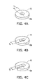
- Figs. 4A to 4C are diagrams schematically illustrating a configuration of the opening portion 6a.
- the opening portion 6a can be the hole which passes through the second connection portion 6 in the thickness direction.
- the dimension L 2 of the opening portion 6a can be the smallest in the dimensions of the cross section of the opening portion 6a.
- the dimension L 2 can be a diameter of the opening portion 6a.
- the dimension L 2 can be the length of one side of the opening portion 6a.
- the opening portion 6a can be a slit which passes through the second connection portion 6 in the thickness direction.
- the dimension L 2 of the opening portion 6a can be the smallest in the dimensions of the cross section of the opening portion 6a.
- the dimension L 2 of the opening portion 6a can be a dimension of the width of the slit.
- the opening portion 6a can be a slit which passes through the second connection portion 6 in the thickness direction, and one end of which opens toward the periphery of the second connection portion 6.
- the dimension L 2 of the opening portion 6a can be the smallest in the dimensions of the cross section of the opening portion 6a.
- the dimension L 2 of the opening portion 6a can be a dimension of the width of the slit.
- a material of the second connection portion 6 is not particularly limited as long as it is an electrically conducting material.
- the material of the second connection portion 6 can be, for example, a copper alloy such as phosphor bronze.
- a film, which is formed of tin or the like on the surface of the second connection portion 6.
- the second connection portion 6 is joined to the first connection portion 5 which is provided on the surface of the substrate 2 through the soldering.
- first connection portion 5 is coated with paste-like solder, and the second connection portion 6 is mounted on the paste-like solder. Then, the second connection portion 6 is joined onto the first connection portion 5 through the soldering, that is, by heating the paste-like solder by a reflow oven.
- the feeding portion 8 is joined to the second connection portion 6 through the soldering.
- first connection portion 5, the second connection portion 6, and the feeding portion 8 can be joined to each other through the soldering at the same time.
- first connection portion 5 and the second connection portion 6 can be coated with the paste-like solder, and then the feeding portion 8 can be inserted into the opening portion 6a of the second connection portion 6. Then, the first connection portion 5, the second connection portion 6, and the feeding portion 8 can be joined to each other at the same time through the soldering, that is, by heating the paste-like solder by a reflow oven.
- Fig. 5 is a diagram schematically illustrating a second connection portion 16 according to another embodiment. As illustrated in Fig. 5 , the second connection portion 16 is joined to the first connection portion 5 through the soldering.
- the second connection portion 16 includes a base portion 16b (corresponding to an example of the first base portion) which is formed into a plate shape and a projection portion 16c which projects toward the substrate 2 from one end surface of the base portion 16b.
- the second connection portion 16 includes an opening portion 16a (corresponding to an example of the first opening portion) passes through the base portion 16b and the projection portion 16c in the thickness direction.
- the opening portion 16a is configured to insert the feeding portion 8 thereinto.
- the configuration of the opening portion 16a can be, for example, the same as that of the opening portion 6a as illustrated in Figs. 4A to 4C .
- the projection portion 16c is configured to be inserted into the inside of the hole 2a of the substrate 2. For this reason, it is possible to join the first connection portion 5 and the second connection portion 16 through the soldering in a state in which the projection portion 16c is inserted into the inside of the hole 2a of the substrate 2. If it is possible to join the first connection portion 5 and the second connection portion 16 through the soldering in a state in which the projection portion 16c is inserted into the inside of the hole 2a of the substrate 2, the positional relationship between the first connection portion 5 and the second connection portion 16 is not deviated even when the solder is melted. For this reason, it is possible to make the state of the soldering portion 7 stable.
- the dimension L 2 of the opening portion 16a of the second connection portion 16 is smaller than the dimension L 1 of the opening portion 5a of the first connection portion 5.
- the first connection portion 5 may be provided on the surface of the substrate 2 on which the wiring portion 3 is provided, and thus it is possible to suppress an increase in the manufacturing cost of the substrate 2.
- Fig. 6 is a diagram schematically illustrating a second connection portion 26 according to still another embodiment.
- Fig. 6A illustrates a case where the feeding portion 8 is inserted into the first connection portion 5 and the second connection portion 26
- Fig. 6B illustrates a case where the feeding portion 8 is inserted into the second connection portion 26.
- the second connection portion 26 is joined to the first connection portion 5 through the soldering.
- the second connection portion 26 includes a base portion 26b (corresponding to an example of the first base portion) which is formed into a plate shape, a projection portion 26c which projects toward the substrate 2 from the base portion 26b, and a base portion 26d (corresponding to an example of the second base portion) which is provided on the projection portion 26c on the side opposite to the side on which the base portion 26b is provided.
- the base portion 26d is formed into a plate shape, and is substantially in parallel with the base portion 26b.
- the base portion 26d projects toward the outside of the second connection portion 26.
- the base portion 26d is joined to the first connection portion 5 through the soldering. When the base portion 26d is provided, it is possible to improve the strength of the joining the base portion 26d and the first connection portion 5 through the soldering.
- the second connection portion 26 includes an opening portion 26a (corresponding to an example of the first opening portion) which passes through the base portion 26b in the thickness direction.
- the opening portion 26a is configured to insert the feeding portion 8 thereinto.
- the configuration of the opening portion 26a can be, for example, the same as that of the opening portion 6a as illustrated in Figs. 4A to 4C .
- the substrate 2 is formed by using the material having the high thermal conductivity. If the substrate 2 is formed of the material having the high thermal conductivity, when joining the feeding portion 8 through the soldering, the heat is likely to be dissipated to the substrate 2. For this reason, it is difficult to perform the solder-joint. In addition, if the heat is transferred to the substrate 2 when joining the feeding portion 8 through the soldering, there is a concern in that the mounted light emitting element 4 or the like is adversely affected by the heat.
- the feeding portion 8 is joined to the base portion 26b through the soldering. For this reason, it is possible to elongate the distance between a position where the feeding portion 8 is joined through soldering and the substrate 2 as compared with a case illustrated in Figs. 3A and 3B . As a result, when joining the feeding portion 8 through the soldering, it is possible to suppress heat dissipation to the substrate 2. Accordingly, it is possible to realize the facilitation of the solder-joint, the reduction of the influence of the mounted light emitting element 4, or the like. For example, it is possible to efficiently perform the solder-joint in a short time. Alternatively, it is possible to perform the solder-joint at a low temperature, and thus thermal damage to the substrate 2, the light emitting element 4, and the like can be reduced.
- the dimension L 2 of the opening portion 16a of the base portion 26b is smaller than the dimension L 1 of the opening portion 5a of the first connection portion 5.
- first connection portion 5 may be provided on the surface of the substrate 2 on the side on which the wiring portion 3 is provided, it is possible to suppress the increase in the manufacturing cost of the substrate 2.
- Fig. 7 is a diagram schematically illustrating the second connection portion 36 according to still another embodiment. Meanwhile, Fig. 7A illustrates a case where the feeding portion 8 is inserted into the first connection portion 5 and the second connection portion 36, and Fig. 7B illustrates a case where the feeding portion 8 is inserted into the second connection portion 36. As illustrated in Figs. 7A and 7B , the second connection portion 36 is joined to the first connection portion 5 through the soldering.
- the second connection portion 36 includes a base portion 36b (corresponding to an example of the first base portion) which is formed into a plate shape, a projection portion 36c which projects toward the substrate 2 from the base portion 36b, and a base portion 36d (corresponding to an example of the second base portion) which is provided on the projection portion 36c on the side opposite to the side on which the base portion 36b is provided.
- the base portion 36d is formed into a plate shape, and is substantially parallel with the base portion 36b.
- the base portion 36d projects toward the inside of the second connection portion 36.
- the base portion 36d is joined to the first connection portion 5 through the soldering. When the base portion 36d is provided, it is possible to improve the strength of the joining the base portion 36d and the first connection portion 5 through the soldering.
- the second connection portion 36 includes an opening portion 36a (corresponding to an example of the first opening portion) which passes through the base portion 36b in the thickness direction.
- the opening portion 36a is configured to insert the feeding portion 8 thereinto.
- the configuration of the opening portion 36a can be, for example, the same as that of the opening portion 6a as illustrated in Figs. 4A to 4C .
- the base portion 36d projects toward the inside of the second connection portion 36, it is possible to realize the reduction in size of the second connection portion 36.
- Fig. 8 is a diagram schematically illustrating a lighting tool for vehicle 100 which is provided with the light emitting device 1 according to the present embodiment.
- Fig. 8A is a cross-sectional view schematically illustrating the lighting tool for vehicle 100.
- Fig. 8B is an enlarged view schematically illustrating an engagement portion of the light emitting device 1 and the lighting tool for vehicle 100.
- the lighting tool for vehicle 100 includes a reflector 120, a lens 150, and the light emitting device 1.
- the appearance of the reflector 120 is substantially formed into a circular truncated cone shape and has a space therein.
- An inner surface of the reflector 120 is formed into an inclined surface, and the light emitted from the light emitting device 1 is reflected in the inclined surface.
- the lens 150 is provided to block an opening 140a having a large cross-sectional area in the reflector 120.
- the light emitting device 1 is provided to block an opening 140b having a small cross-sectional area in the reflector 120.
- the light which is emitted from the light emitting device 1 is directly emitted to the outside via the lens 150, or the light is reflected in the inner surface of the reflector 120 and then emitted to the outside via the lens 150.
- the lighting tool for vehicle 100 can be, for example, provided in a taillight portion of a vehicle or the like.
- a seal 160 which is formed of a material such as rubber or silicone can be provided between the light emitting device 1 and the reflector 120.
- the light emitting device 1 and the lighting tool for vehicle 100 may be firmly engaged with each other by providing an engagement projection 19 on the light emitting device 1.
- an engagement opening (not shown) corresponding to the engagement projection 19 may be provided in the lighting tool for vehicle 100.
- an engagement unit (not shown) which is formed of an elastic body or the like may be provided in the lighting tool for vehicle 100. That is, a unit configured to firmly engage the light emitting device 1 and the lighting tool for vehicle 100 with each other can be properly provided.
Landscapes
- Engineering & Computer Science (AREA)
- General Engineering & Computer Science (AREA)
- Manufacturing & Machinery (AREA)
- Microelectronics & Electronic Packaging (AREA)
- Led Device Packages (AREA)
- Connections Effected By Soldering, Adhesion, Or Permanent Deformation (AREA)
Abstract
Description
- Embodiments described below are generally related to a light emitting device.
- There is a light emitting device on which a light emitting element such as a light emitting diode (LED) is provided. This light emitting device is provided with a connection portion for performing an electrical connection between a wiring pattern which is provided on a substrate and a feeding portion to which an electric power is supplied from the outside. Then, generally, the wiring pattern is joined to the feeding portion through soldering in the connection portion.
- For this reason, improvement of reliability of soldering in the connection portion which joins the feeding portion is required.
- PTL 1:
JP-A-2002-124761 - An object of the present invention is to provide a light emitting device capable of improving reliability of soldering in a connection portion which joins a feeding portion.
- A light emitting device according to the present embodiment includes a substrate on which a wiring portion is provided, a light emitting element which is provided on the substrate and is electrically connected to the wiring portion, a feeding portion to which an electric power is supplied from the outside, a first connection portion which is provided on the substrate and is electrically connected to the wiring portion, a second connection portion which is joined to the first connection portion through soldering and includes a first opening portion into which the feeding portion is inserted, and a soldering portion which is provided between the first opening portion and the feeding portion.
- According to the embodiment of the invention, it is possible to provide a light emitting device capable of improving a reliability of soldering in a connection portion which joins a feeding portion.
-
- [
Fig. 1] Figs. 1A and 1B are diagrams schematically illustrating alight emitting device 1 according to the present embodiment. - [
Fig. 2] Figs. 2A and 2B are diagrams schematically illustrating afirst connection portion 5, asecond connection portion 6, and asoldering portion 7. - [
Fig. 3] Figs. 3A and 3B are diagrams schematically illustratingconnection portions - [
Fig. 4] Figs. 4A to 4C are diagrams schematically illustrating a configuration of anopening portion 6a. - [
Fig. 5] Fig. 5 is a diagram schematically illustrating asecond connection portion 16 according to another embodiment. - [
Fig. 6] Figs. 6A and 6B are diagrams schematically illustrating asecond connection portion 26 according to still another embodiment. - [
Fig. 7] Figs. 7A and 7B are diagrams schematically illustrating asecond connection portion 36 according to still another embodiment. - [
Fig. 8] Figs. 8A and 8B are diagrams schematically illustrating a lighting tool forvehicle 100 which is provided with thelight emitting device 1 according to the present embodiment. - A first invention relates to a light emitting device including a substrate on which a wiring portion is provided; a light emitting element which is provided on the substrate and is electrically connected to the wiring portion; a feeding portion to which an electric power is supplied from the outside; a first connection portion which is provided on the substrate and is electrically connected to the wiring portion; a second connection portion which is joined to the first connection portion through soldering and includes a first opening portion into which the feeding portion is inserted; and a soldering portion which is provided between the first opening portion and the feeding portion.
- According to the light emitting device, it is possible to shorten the distance between the second connection portion and the feeding portion. For this reason, when joining the second connection portion and the feeding portion through soldering, the solder is likely to spread to the second connection portion and the feeding portion, and thus a normal fillet is easily formed. As a result, the strength and reliability in a soldering portion can be improved.
- A second invention relates to the light emitting device according to the first invention in which the first connection portion has a second opening portion, and the first opening portion is smaller than the second opening portion.
- According to the light emitting device, it is possible to shorten the distance between the second connection portion and the feeding portion. For this reason, when joining the second connection portion and the feeding portion through the soldering, the solder is likely to spread to the second connection portion and the feeding portion, and thus a normal fillet is easily formed. As a result, the strength and reliability in a soldering portion can be improved.
- A third invention relates to the light emitting device according to the first invention in which the second connection portion includes a first base portion and a projection portion which projects toward the substrate from the first base portion, and the first opening portion passes through the first base portion and the projection portion in the thickness direction.
- According to the light emitting device, when joining the first connection portion and the second connection portion through the soldering, it is possible to suppress a deviation of a positional relationship therebetween.
- A fourth invention relates to the light emitting device according to the third invention in which the projection portion is inserted into a hole which is provided in the substrate.
- According to the light emitting device, since it is possible to join the first connection portion and the second connection portion through the soldering in a state where the projection portion is inserted into the inside of the hole of the substrate, the positional relationship between the first connection portion and the second connection portion is not deviated even when the solder is melted. For this reason, it is possible to make the state of the soldering portion stable.
- A fifth invention relates to the light emitting device according to the first invention in which the second connection portion includes a first base portion, a projection portion which projects toward the substrate from the first base portion, and a second base portion which is provided on the projection portion on the side opposite to the side on which the first base portion is provided, the second base portion projects toward the outside of the second connection portion, and the first opening portion passes through the first base portion in the thickness direction.
- According to the light emitting device, it is possible to elongate the distance between a position where the feeding portion is joined through soldering and the substrate. For this reason, when joining the feeding portion through the soldering, it is possible to suppress heat dissipation to the substrate. Accordingly, it is possible to realize facilitation of solder-joint, and reduction of an influence of the mounted light emitting element.
- A sixth invention relates to the light emitting device according to the first invention, in which the second connection portion includes a first base portion, a projection portion which projects toward the substrate from the first base portion, and a second base portion which is provided on the projection portion on the side opposite to the side on which the first base portion is provided, the second base portion projects toward the inside of the second connection portion, and the first opening portion passes through the first base portion in the thickness direction.
- According to the light emitting device, it is possible to elongate the distance between a position where the feeding portion is joined through soldering and the substrate. For this reason, when joining the feeding portion through the soldering, it is possible to suppress heat dissipation to the substrate. Accordingly, it is possible to realize facilitation of the solder-joint, reduction of an influence of the mounted light emitting element.
- Furthermore, the second base portion projects toward the inside of the second connection portion, and thus it is possible to realize the reduction in size of the second connection portion. In addition, it is possible to make a mounted area in the substrate small due to the reduction in size of the second connection portion, and therefore, it is possible to realize the reduction in size of the light emitting device.
- A seventh invention relates to a light emitting device including a substrate on which a wiring portion is provided; a light emitting element which is provided on the substrate and is electrically connected to the wiring portion; a first connection portion which is provided on the substrate and is electrically connected to the wiring portion; and a second connection portion which is joined to the first connection portion through the soldering and includes a first opening portion into which the feeding portion to which an electric power is supplied from the outside is inserted.
- According to the light emitting device, it is possible to shorten the distance between the second connection portion and the feeding portion. For this reason, when joining the second connection portion and the feeding portion through the soldering, the solder is likely to spread to the second connection portion and the feeding portion, and thus a normal fillet is easily formed. As a result, the strength and reliability in a soldering portion can be improved.
- An eighth invention relates to the light emitting device according to the seventh invention in which the first connection portion includes a second opening portion, and the first opening portion is smaller than the second opening portion.
- According to the light emitting device, it is possible to shorten the distance between the second connection portion and the feeding portion. For this reason, when joining the second connection portion and the feeding portion through the soldering, the solder is likely to spread to the second connection portion and the feeding portion, and thus a normal fillet is easily formed. As a result, the strength and reliability in a soldering portion can be improved.
- A ninth invention relates to the light emitting device according to the seventh invention in which the second connection portion includes a first base portion and a projection portion which projects toward the substrate from the first base portion, and the first opening portion passes through the first base portion and the projection portion in the thickness direction.
- According to the light emitting device, when joining the first connection portion and the second connection portion through the soldering, it is possible to suppress the deviation of a positional relationship therebetween.
- A tenth invention relates to the light emitting device according to the ninth invention in which the projection portion is inserted into a hole which is provided in the substrate.
- According to the light emitting device, since it is possible to join the first connection portion and the second connection portion through the soldering in a state where the projection portion is inserted into the inside of the hole of the substrate, the positional relationship between the first connection portion and the second connection portion is not deviated even when the solder is melted. For this reason, it is possible to make the state of the soldering portion stable.
- An eleventh invention relates to the light emitting device according to the seventh invention in which the second connection portion includes a first base portion, a projection portion which projects toward the substrate from the first base portion, and a second base portion which is provided on the projection portion on the side opposite to the side on which the first base portion is provided, the second base portion projects toward the outside of the second connection portion, and the first opening portion passes through the first base portion in the thickness direction.
- According to the light emitting device, it is possible to elongate the distance between a position where the feeding portion is joined through soldering and the substrate. For this reason, when joining the feeding portion through the soldering, it is possible to suppress heat dissipation to the substrate. Accordingly, it is possible to realize facilitation of the solder-joint, reduction of an influence of the mounted light emitting element.
- A twelfth invention relates to the light emitting device according to the seventh invention in which the second connection portion includes a first base portion, a projection portion which projects toward the substrate from the first base portion, and a second base portion which is provided on the projection portion on the side opposite to the side on which the first base portion is provided, the second base portion projects toward the inside of the second connection portion, and the first opening portion passes through the first base portion in the thickness direction.
- According to the light emitting device, it is possible to elongate the distance between a position where the feeding portion is joined through soldering and the substrate. For this reason, when joining the feeding portion through the soldering, it is possible to suppress heat dissipation to the substrate. Accordingly, it is possible to realize facilitation of the solder-joint, reduction of an influence of the mounted light emitting element.
- Furthermore, the second base portion projects toward the inside of the second connection portion, and thus it is possible to realize the reduction in size of the second connection portion. In addition, it is possible to make a mounted area in the substrate small due to the reduction in size of the second connection portion, and therefore, it is possible to realize the reduction in size of the light emitting device.
- Hereinafter, description will be given of the embodiment with reference to drawings. In addition, like reference numerals are given to like elements in the drawings and description thereof is properly omitted.
Fig. 1 is a diagram schematically illustrating alight emitting device 1 according to the present embodiment. - Meanwhile,
Fig. 1A is a schematic perspective view when viewing thelight emitting device 1 from the front side, andFig. 1B is a schematic perspective view when viewing thelight emitting device 1 from the rear side. - As illustrated in
Figs. 1A and 1B , thelight emitting device 1 is provided with asubstrate 2, awiring portion 3, alight emitting element 4, afirst connection portion 5, asecond connection portion 6, asoldering portion 7, and afeeding portion 8. - The
substrate 2 is formed into a plate shape and is provided with thewiring portion 3 on the surface thereof. - There is no particular limit to a material and a structure of the
substrate 2. For example, thesubstrate 2 can be formed of an inorganic material (ceramics) such as aluminum oxide or aluminum nitride, or an organic material such as paper phenol or glass epoxy. In addition, thesubstrate 2 may be formed by coating a surface of a metallic plate with an insulator. Meanwhile, if the surface of the metallic plate is coated with the insulator, the insulator may be formed of the organic material or the inorganic material. - Here, if a heating value of the
light emitting element 4 is high, it is preferable that thesubstrate 2 is formed by using a material having high thermal conductivity in terms of the heat dissipation. Examples of the material having the high thermal conductivity are, for example, the ceramics such as the aluminum oxide or the aluminum nitride, a heat conductive resin, or a metallic plate of which a surface is coated with an insulator. - In addition, the
substrate 2 may be one plate-like body or may be a plurality of divided plate-like bodies. Further, thesubstrate 2 may be a single layer or may be a multilayer. - The
wiring portion 3 is provided on at least one surface of thesubstrate 2. Thewiring portion 3 can be assumed to be, for example, a wiring pattern. - In this case, the
wiring portion 3 can be provided on both surfaces of thesubstrate 2, but, in order to reduce manufacturing cost, is preferably provided on one surface of thesubstrate 2. Thelight emitting element 4 is provided on thesubstrate 2, and is electrically connected to thewiring portion 3. If thewiring portion 3 is the wiring pattern, thelight emitting element 4 can be mounted on the wiring pattern. In addition, a circuit component (not shown) such as a capacitor or a resistor may be electrically connected to thewiring portion 3. - A method of connecting the
light emitting element 4 or the circuit component (not shown) is not particularly limited. For example, thelight emitting element 4 or the circuit component may be mounted through flip chip, may be mounted through a wire bonding method, or may be joined through the soldering. - The
light emitting element 4 can be a so-called spontaneous light emitting element, for example, a light emitting diode, an organic light emitting diode, and a laser diode. - A radiation surface of the
light emitting element 4 faces the front side of thelight emitting device 1, and light is mainly radiated toward the front side of thelight emitting device 1. The number of thelight emitting elements 4 is not particularly limited, and one or more of thelight emitting elements 4 may be provided depending on a use of thelight emitting device 1 or the size of thelight emitting element 4. If a plurality of thelight emitting elements 4 are provided, a regular form of arrangement such as a linear pattern, a matrix pattern, a zigzag pattern, and a radial pattern, can be employed or an optional form of arrangement can be also employed. - The
first connection portion 5 is provided on thesubstrate 2 and is electrically connected to thewiring portion 3. - The
first connection portion 5 includes anopening portion 5a (corresponding to an example of the second opening portion) (refer toFig. 2 ). - A dimension L1 of the
opening portion 5a is larger than a dimension L3 of the hole (a through hole) 2a which passes through thesubstrate 2 in the thickness direction. - The
first connection portion 5 can be, for example, a land which is provided in the periphery of thehole 2a. - Note that, as will be described later, if the
hole 2a is not provided, theopening portion 5a is not necessarily required. If theopening portion 5a is not provided, thefirst connection portion 5 can be, for example, a pad which is provided at a predetermined position of thesubstrate 2. - In addition, for example, the land can be formed into a ring shape and the pad can be formed into a circle, but shapes thereof are not limited. It is possible to properly change the shape of the land or the pad.
- The
second connection portion 6 is joined to thefirst connection portion 5 through the soldering. - The
second connection portion 6 is joined to thefirst connection portion 5 through the soldering, and includes theopening portion 6a (corresponding to an example of the first opening portion) to which thefeeding portion 8 is inserted. - The
soldering portion 7 is provided between the openingportion 6a and the feedingportion 8. Thesoldering portion 7 is formed by joining thesecond connection portion 6 and the feedingportion 8 through soldering. - Meanwhile, descriptions of the
first connection portion 5, thesecond connection portion 6, and thesoldering portion 7 will be made later in detail. - The electric power is supplied to the feeding
portion 8 from the outside. - The feeding
portion 8 extends in the inside of asocket 10 in the forward and backward direction. - As illustrated in
Fig. 1A , the feedingportion 8 projects forward from the surface of thesubstrate 2. In addition, as illustrated inFig. 1B , the feedingportion 8 projects rearward on the inside of aconnector inserting portion 10c which is provided in thesocket 10. - The feeding
portion 8 is electrically connected to a connector (not shown) which is inserted from the rear side of thesocket 10, and to which the electric power is supplied from the outside. For this reason, it is possible to supply the electric power to thelight emitting element 4 through the feedingportion 8, thefirst connection portion 5, thesecond connection portion 6, and thesoldering portion 7. - Note that the configuration of the feeding
portion 8 is not limited to the above description. For example, the number of thefeeding portions 8 may be three or more without being limited to two. In addition, a cross sectional shape of the feedingportion 8 may be a circle or the like without limiting to a rectangle. - A material of the feeding
portion 8 is not particularly limited as long as it is an electrically conducting material. The material of the feedingportion 8 can be, for example, a copper alloy. - In addition, the
light emitting device 1 can be provided with areflector 9. - The
reflector 9 is provided to surround thelight emitting elements 4. - The
reflector 9 is formed into, for example, a ring shape, and is formed to expose thelight emitting element 4 to acenter portion 9a. - The
reflector 9 can be formed of, for example, resin or ceramics. - A wall surface of the
center portion 9a of thereflector 9 is formed into an inclined surface. A part of light radiated from thelight emitting element 4 is reflected in the wall surface of thecenter portion 9a of thereflector 9 and is irradiated toward the front side of thelight emitting device 1. Meanwhile, the configuration of thereflector 9 can be properly changed without being limited to the above description. - In addition, the
center portion 9a of thereflector 9 can be filled with a resin. Examples of the resin with which thecenter portion 9a of thereflector 9 is filled include a silicone resin and the like. When thecenter portion 9a of thereflector 9 is filled with the resin, it is possible to suppress the mechanical contact from the outside with respect to thelight emitting element 4 or the like, and the air and moisture attaching to thelight emitting element 4 or the like. For this reason, it is possible to improve the reliability with respect to light emittingdevice 1. - Further, the resin with which the
center portion 9a of thereflector 9 is filled can include a phosphor. The phosphor can be, for example, a YAG phosphor (yttrium-aluminum-garnet phosphor-based). If thelight emitting element 4 is a blue light emitting diode and the phosphor is the YAG phosphor, the YAG phosphor is excited by the blue light emitted from thelight emitting element 4, and a yellow fluorescence is radiated from the YAG phosphor. Then, due to the blue light and the yellow light which are mixed to each other, white light is emitted from thelight emitting device 1. Meanwhile, types of the phosphors and thelight emitting element 4 are not limited to the above description, and it is possible to properly change types thereof depending of the use of thelight emitting device 1 so as to obtain a desired emission color. - In addition, the
light emitting device 1 can be provided with thesocket 10. - The
socket 10 can hold, for example, thesubstrate 2 or have the feedingportion 8 built therein. In addition, as illustrated inFigs. 1A and 1B , thesocket 10 may have a structure in which aresin portion 10a and a heat dissipation member (heat sink) 10b are combined with each other. Alternatively, thesocket 10 may have a structure formed by either of theresin portion 10a and theheat dissipation member 10b. - The
substrate 2 may be fixed to the front surface of thesocket 10 by using an adhesive, a double sided tape, or the like, or may be fixed to the front surface of thesocket 10 by using a fastening member such as a screw or the like. In addition, thesubstrate 2 may be fixed to the front surface of thesocket 10 by using an elastic member such as the spring. - Next, descriptions pertaining to the
first connection portion 5, thesecond connection portion 6, and thesoldering portion 7 will be made.Fig. 2 is a diagram schematically illustrating thefirst connection portion 5, thesecond connection portion 6, and thesoldering portion 7. - Meanwhile,
Fig. 2A illustrates a case where the feedingportion 8 is inserted into thefirst connection portion 5 and thesecond connection portion 6, andFig. 2B illustrates a case where the feedingportion 8 is inserted into thesecond connection portion 6. -
Fig. 3 is a diagram schematically illustratingconnection portions - Meanwhile,
Fig. 3A illustrates a case of theconnection portion 105a which is provided on one surface of thesubstrate 2, andFig. 3B illustrates a case of theconnection portion 105b which is provided in the inside of thehole 2a passing through thesubstrate 2 in the thickness direction and in the periphery of thehole 2a. - First, description pertaining to the
connection portions Fig. 3 will be made. Pertaining to thelight emitting device 1 which is provided with thelight emitting elements 4, the reduction in size is desired so as to realize the reduction in material, the reduction in weight, or the like. In addition, the realization of high quality and low cost of thelight emitting device 1 is also desired. - In this case, it is possible to realize the low cost by reducing the area of the
substrate 2 and providing thewiring portion 3 on one surface of the substrate 2 (a single-sided wiring). - If the
wiring portion 3 is provided on one surface of thesubstrate 2, generally, the connection portion (the land) 105a is provided at a position which is far away, by a certain distance, from the periphery of thehole 2a which passes through thesubstrate 2 in the thickness direction, as illustrated inFig. 3A . - However, when providing such a
connection portion 105a, the distance between theconnection portion 105a and the feedingportion 8 becomes longer. For this reason, when joining theconnection portion 105a and the feedingportion 8 through the soldering, asoldering portion 107a is likely to be formed into a bridge shape. When thesoldering portion 107a is formed into the bridge shape, the shape of thesoldering portion 107a becomes unstable in a process of solder-joint, and thereby a defect such as a hole is liable to be generated in a portion of thesoldering portion 107a. Thus, if the defect is generated in thesoldering portion 107a, there is a concern in that thesoldering portion 107a is not sufficiently strong with respect to the thermal shock, an external force, or the like. - In contrast, as illustrated in
Fig. 3B , when theconnection portion 105b is provided in the inside of thehole 2a which passes through thesubstrate 2 in the thickness direction and in the periphery of thehole 2a, that is, both surfaces of thesubstrate 2, it is possible to shorten the distance between theconnection portion 105b and the feedingportion 8. For this reason, when joining theconnection portion 105b and the feedingportion 8 through the soldering, the solder is likely to spread to theconnection portion 105b and the feedingportion 8, and thus a normal fillet is easily formed. For this reason, the strength and reliability in asoldering portion 107b can be improved. - However, since it is necessary to provide the
connection portion 105b in the inside of thehole 2a and the surface of thesubstrate 2 on which thewiring portion 3 is not provided, there is a concern in that the manufacturing cost of thesubstrate 2 becomes 1.5 times to 2 times. - Next, returning to
Fig. 2 , description pertaining to thefirst connection portion 5 and thesecond connection portion 6 will be made. - As illustrated in
Figs. 2A and 2B , thefirst connection portion 5 is provided at a position which is far away, by a certain distance, from the periphery of thehole 2a which passes through thesubstrate 2 in the thickness direction. - In this case, in a case of a diagram illustrated in
Fig. 2A , thehole 2a is provided to insert the feedingportion 8 thereinto. For this reason, in a case of the diagram illustrated inFig. 2A , thefirst connection portion 5 can be the ring-shaped land or the like which is provided in the periphery of thehole 2a. - On the other hand, in a case of a diagram illustrated in
Fig. 2B , thehole 2a is not necessarily provided to insert the feedingportion 8 thereinto. However, if thehole 2a is provided, the positioning of the feedingportion 8 when joining the feedingportion 8 through the soldering, and inspection of thesoldering portion 7 on thesubstrate 2 side are easily performed. - For this reason, in a case of a diagram illustrated in
Fig. 2B , if thehole 2a is provided, thefirst connection portion 5 can be the ring-shaped land or the like which is provided in the periphery of thehole 2a. In addition, if thehole 2a is not provided, thefirst connection portion 5 can be the circular pad or the ring-shaped land which is provided at a predetermined position. - The
first connection portion 5 is formed of the conducting material, and is electrically connected to thewiring portion 3. Thefirst connection portion 5 and thewiring portion 3 may be formed at the same time. - The
second connection portion 6 is joined to thefirst connection portion 5 through the soldering. - The
second connection portion 6 is formed into a plate shape, and includes theopening portion 6a into which thefeeding portion 8 is inserted. - Then, the dimension L2 of the
opening portion 6a of thesecond connection portion 6 is smaller than the dimension L1 of theopening portion 5a of thefirst connection portion 5. - For this reason, as illustrated in
Figs. 2A and 2B , the distance between thefirst connection portion 5 and the feedingportion 8 becomes longer, but it is possible to shorten the distance between thesecond connection portion 6 and the feedingportion 8. - In this case, the feeding
portion 8 is joined to thesecond connection portion 6 through the soldering. For this reason, if thesecond connection portion 6 and the feedingportion 8 are joined to each other through the soldering, the solder is likely to spread to thesecond connection portion 6 and the feedingportion 8, and thus a normal fillet is easily formed. As a result, the strength and reliability in thesoldering portion 7 can be improved. - In addition, as illustrated in
Fig. 3B , thefirst connection portion 5 is not necessarily provided in the inside of thehole 2a and on the surface of thesubstrate 2 on which thewiring portion 3 is not provided. That is, thefirst connection portion 5 may be provided on the surface of thesubstrate 2 on which thewiring portion 3 is provided. For this reason, it is possible to suppress the manufacturing cost of thesubstrate 2. -
Figs. 4A to 4C are diagrams schematically illustrating a configuration of theopening portion 6a. - As illustrated in
Fig. 4A , theopening portion 6a can be the hole which passes through thesecond connection portion 6 in the thickness direction. In this case, the dimension L2 of theopening portion 6a can be the smallest in the dimensions of the cross section of theopening portion 6a. For example, if the cross section of theopening portion 6a is a circle, the dimension L2 can be a diameter of theopening portion 6a. If the cross section of theopening portion 6a is a square, the dimension L2 can be the length of one side of theopening portion 6a. - As illustrated in
Fig. 4B , theopening portion 6a can be a slit which passes through thesecond connection portion 6 in the thickness direction. In this case, the dimension L2 of theopening portion 6a can be the smallest in the dimensions of the cross section of theopening portion 6a. For example, as illustrated inFig. 4B , the dimension L2 of theopening portion 6a can be a dimension of the width of the slit. - As illustrated in
Fig. 4C , theopening portion 6a can be a slit which passes through thesecond connection portion 6 in the thickness direction, and one end of which opens toward the periphery of thesecond connection portion 6. In this case, the dimension L2 of theopening portion 6a can be the smallest in the dimensions of the cross section of theopening portion 6a. For example, as illustrated inFig. 4C , the dimension L2 of theopening portion 6a can be a dimension of the width of the slit. - A material of the
second connection portion 6 is not particularly limited as long as it is an electrically conducting material. The material of thesecond connection portion 6 can be, for example, a copper alloy such as phosphor bronze. In consideration of wettability of the solder when performing solder-joint, it is possible to provide a film, which is formed of tin or the like, on the surface of thesecond connection portion 6. For example, it is possible to provide a film formed of tin or the like on the surface of thesecond connection portion 6 through plating. - Next, a process of soldering will be exemplified.
- First, the
second connection portion 6 is joined to thefirst connection portion 5 which is provided on the surface of thesubstrate 2 through the soldering. - For example, the surface of
first connection portion 5 is coated with paste-like solder, and thesecond connection portion 6 is mounted on the paste-like solder. Then, thesecond connection portion 6 is joined onto thefirst connection portion 5 through the soldering, that is, by heating the paste-like solder by a reflow oven. - Next, the feeding
portion 8 is joined to thesecond connection portion 6 through the soldering. - For example, it is possible to join the feeding
portion 8 to thesecond connection portion 6 through the soldering by inserting the feedingportion 8 into theopening portion 6a of thesecond connection portion 6. - In addition, the
first connection portion 5, thesecond connection portion 6, and the feedingportion 8 can be joined to each other through the soldering at the same time. - For example, the
first connection portion 5 and thesecond connection portion 6 can be coated with the paste-like solder, and then the feedingportion 8 can be inserted into theopening portion 6a of thesecond connection portion 6. Then, thefirst connection portion 5, thesecond connection portion 6, and the feedingportion 8 can be joined to each other at the same time through the soldering, that is, by heating the paste-like solder by a reflow oven. -
Fig. 5 is a diagram schematically illustrating asecond connection portion 16 according to another embodiment. As illustrated inFig. 5 , thesecond connection portion 16 is joined to thefirst connection portion 5 through the soldering. - The
second connection portion 16 includes abase portion 16b (corresponding to an example of the first base portion) which is formed into a plate shape and aprojection portion 16c which projects toward thesubstrate 2 from one end surface of thebase portion 16b. In addition, thesecond connection portion 16 includes anopening portion 16a (corresponding to an example of the first opening portion) passes through thebase portion 16b and theprojection portion 16c in the thickness direction. Theopening portion 16a is configured to insert the feedingportion 8 thereinto. Meanwhile, the configuration of theopening portion 16a can be, for example, the same as that of theopening portion 6a as illustrated inFigs. 4A to 4C . - In addition, the
projection portion 16c is configured to be inserted into the inside of thehole 2a of thesubstrate 2. For this reason, it is possible to join thefirst connection portion 5 and thesecond connection portion 16 through the soldering in a state in which theprojection portion 16c is inserted into the inside of thehole 2a of thesubstrate 2. If it is possible to join thefirst connection portion 5 and thesecond connection portion 16 through the soldering in a state in which theprojection portion 16c is inserted into the inside of thehole 2a of thesubstrate 2, the positional relationship between thefirst connection portion 5 and thesecond connection portion 16 is not deviated even when the solder is melted. For this reason, it is possible to make the state of thesoldering portion 7 stable. - Further, the dimension L2 of the
opening portion 16a of thesecond connection portion 16 is smaller than the dimension L1 of theopening portion 5a of thefirst connection portion 5. - For this reason, as described above, when joining the
second connection portion 16 and the feedingportion 8 through the soldering, the solder is likely to spread to thesecond connection portion 16 and the feedingportion 8, and thus a normal fillet is easily formed. As a result, the strength and reliability in thesoldering portion 7 can be improved. - In addition, the
first connection portion 5 may be provided on the surface of thesubstrate 2 on which thewiring portion 3 is provided, and thus it is possible to suppress an increase in the manufacturing cost of thesubstrate 2. - Note that the process of solder-joint can be the same as that described above.
-
Fig. 6 is a diagram schematically illustrating asecond connection portion 26 according to still another embodiment. Meanwhile,Fig. 6A illustrates a case where the feedingportion 8 is inserted into thefirst connection portion 5 and thesecond connection portion 26, andFig. 6B illustrates a case where the feedingportion 8 is inserted into thesecond connection portion 26. As illustrated inFigs. 6A and 6B , thesecond connection portion 26 is joined to thefirst connection portion 5 through the soldering. - The
second connection portion 26 includes abase portion 26b (corresponding to an example of the first base portion) which is formed into a plate shape, aprojection portion 26c which projects toward thesubstrate 2 from thebase portion 26b, and abase portion 26d (corresponding to an example of the second base portion) which is provided on theprojection portion 26c on the side opposite to the side on which thebase portion 26b is provided. Thebase portion 26d is formed into a plate shape, and is substantially in parallel with thebase portion 26b. In addition, thebase portion 26d projects toward the outside of thesecond connection portion 26. Thebase portion 26d is joined to thefirst connection portion 5 through the soldering. When thebase portion 26d is provided, it is possible to improve the strength of the joining thebase portion 26d and thefirst connection portion 5 through the soldering. - In addition, the
second connection portion 26 includes anopening portion 26a (corresponding to an example of the first opening portion) which passes through thebase portion 26b in the thickness direction. Theopening portion 26a is configured to insert the feedingportion 8 thereinto. Meanwhile, the configuration of theopening portion 26a can be, for example, the same as that of theopening portion 6a as illustrated inFigs. 4A to 4C . - Here, as described above, if the heating value of the
light emitting element 4 is high like the light emitting diode, thesubstrate 2 is formed by using the material having the high thermal conductivity. If thesubstrate 2 is formed of the material having the high thermal conductivity, when joining the feedingportion 8 through the soldering, the heat is likely to be dissipated to thesubstrate 2. For this reason, it is difficult to perform the solder-joint. In addition, if the heat is transferred to thesubstrate 2 when joining the feedingportion 8 through the soldering, there is a concern in that the mountedlight emitting element 4 or the like is adversely affected by the heat. - In the present embodiment, the feeding
portion 8 is joined to thebase portion 26b through the soldering. For this reason, it is possible to elongate the distance between a position where the feedingportion 8 is joined through soldering and thesubstrate 2 as compared with a case illustrated inFigs. 3A and 3B . As a result, when joining the feedingportion 8 through the soldering, it is possible to suppress heat dissipation to thesubstrate 2. Accordingly, it is possible to realize the facilitation of the solder-joint, the reduction of the influence of the mountedlight emitting element 4, or the like. For example, it is possible to efficiently perform the solder-joint in a short time. Alternatively, it is possible to perform the solder-joint at a low temperature, and thus thermal damage to thesubstrate 2, thelight emitting element 4, and the like can be reduced. - In addition, the dimension L2 of the
opening portion 16a of thebase portion 26b is smaller than the dimension L1 of theopening portion 5a of thefirst connection portion 5. - For this reason, as described above, when joining the
base portion 26b and the feedingportion 8 through the soldering, the solder is likely to spread to thebase portion 26b and the feedingportion 8, and thus a normal fillet is easily formed. As a result, the strength and reliability in thesoldering portion 7 can be improved. - In addition, since the
first connection portion 5 may be provided on the surface of thesubstrate 2 on the side on which thewiring portion 3 is provided, it is possible to suppress the increase in the manufacturing cost of thesubstrate 2. - Note that the process of solder-joint can be the same as that described above.
-
Fig. 7 is a diagram schematically illustrating thesecond connection portion 36 according to still another embodiment. Meanwhile,Fig. 7A illustrates a case where the feedingportion 8 is inserted into thefirst connection portion 5 and thesecond connection portion 36, andFig. 7B illustrates a case where the feedingportion 8 is inserted into thesecond connection portion 36. As illustrated inFigs. 7A and 7B , thesecond connection portion 36 is joined to thefirst connection portion 5 through the soldering. - The
second connection portion 36 includes abase portion 36b (corresponding to an example of the first base portion) which is formed into a plate shape, aprojection portion 36c which projects toward thesubstrate 2 from thebase portion 36b, and abase portion 36d (corresponding to an example of the second base portion) which is provided on theprojection portion 36c on the side opposite to the side on which thebase portion 36b is provided. Thebase portion 36d is formed into a plate shape, and is substantially parallel with thebase portion 36b. In addition, thebase portion 36d projects toward the inside of thesecond connection portion 36. Thebase portion 36d is joined to thefirst connection portion 5 through the soldering. When thebase portion 36d is provided, it is possible to improve the strength of the joining thebase portion 36d and thefirst connection portion 5 through the soldering. - In addition, the
second connection portion 36 includes anopening portion 36a (corresponding to an example of the first opening portion) which passes through thebase portion 36b in the thickness direction. Theopening portion 36a is configured to insert the feedingportion 8 thereinto. Meanwhile, the configuration of theopening portion 36a can be, for example, the same as that of theopening portion 6a as illustrated inFigs. 4A to 4C . - In the present embodiment, since the
base portion 36d projects toward the inside of thesecond connection portion 36, it is possible to realize the reduction in size of thesecond connection portion 36. In addition, it is possible to make a mounted area in thesubstrate 2 small in size due to the reduction in size of thesecond connection portion 36, and therefore, it is possible to realize the reduction in size of thelight emitting device 1. - In addition, similar to the case of the
second connection portion 26 as described above, it is possible to suppress heat dissipation to thesubstrate 2 when joining the feedingportion 8 through the soldering, the strength and reliability in thesoldering portion 7 can be improved since a normal fillet is easily formed, and it is possible to suppress an increase in the manufacturing cost of thesubstrate 2. - Note that the process of solder-joint can be the same as that described above.
-
Fig. 8 is a diagram schematically illustrating a lighting tool forvehicle 100 which is provided with thelight emitting device 1 according to the present embodiment. - Meanwhile,
Fig. 8A is a cross-sectional view schematically illustrating the lighting tool forvehicle 100.Fig. 8B is an enlarged view schematically illustrating an engagement portion of thelight emitting device 1 and the lighting tool forvehicle 100. - The lighting tool for
vehicle 100 includes areflector 120, alens 150, and thelight emitting device 1. - The appearance of the
reflector 120 is substantially formed into a circular truncated cone shape and has a space therein. An inner surface of thereflector 120 is formed into an inclined surface, and the light emitted from thelight emitting device 1 is reflected in the inclined surface. - The
lens 150 is provided to block anopening 140a having a large cross-sectional area in thereflector 120. - The
light emitting device 1 is provided to block anopening 140b having a small cross-sectional area in thereflector 120. - The light which is emitted from the
light emitting device 1 is directly emitted to the outside via thelens 150, or the light is reflected in the inner surface of thereflector 120 and then emitted to the outside via thelens 150. - The lighting tool for
vehicle 100 can be, for example, provided in a taillight portion of a vehicle or the like. - A portion, which is formed in the
socket 10 of thelight emitting device 1 and on the front side from aflange portion 17, is in a state of being surrounded by thereflector 120 and thelens 150. In this case, it is possible to closely adhere thelight emitting device 1 and thereflector 120 to each other so as to prevent water from entering. For example, if necessary, aseal 160 which is formed of a material such as rubber or silicone can be provided between the light emittingdevice 1 and thereflector 120. - Note that, as illustrated in
Fig. 8B , thelight emitting device 1 and the lighting tool forvehicle 100 may be firmly engaged with each other by providing anengagement projection 19 on thelight emitting device 1. In addition, an engagement opening (not shown) corresponding to theengagement projection 19 may be provided in the lighting tool forvehicle 100. Further, an engagement unit (not shown) which is formed of an elastic body or the like may be provided in the lighting tool forvehicle 100. That is, a unit configured to firmly engage thelight emitting device 1 and the lighting tool forvehicle 100 with each other can be properly provided. - As above, embodiments are given of the present invention, but these embodiments are described as examples, and thus are not intended to limit the scope of the invention. These novel embodiments described herein may be implemented in various other forms and it is possible to perform various omissions, substitutions, and changes without departing from the scope of the invention. These embodiments and modification examples thereof are within the scope and the gist of the invention and within the scope of its equivalents as the inventions described in claims. In addition, the above described embodiments can be implemented in combination with each other.
Claims (12)
- A light emitting device comprising:a substrate on which a wiring portion is provided;a light emitting element which is provided on the substrate and is electrically connected to the wiring portion;a feeding portion to which an electric power is supplied from the outside;a first connection portion which is provided on the substrate and is electrically connected to the wiring portion;a second connection portion which is joined to the first connection portion through soldering and includes a first opening portion into which the feeding portion is inserted; anda soldering portion which is provided between the first opening portion and the feeding portion.
- The device according to claim 1,
wherein the first connection portion includes a second opening portion, and
wherein the first opening portion is smaller than the second opening portion. - The device according to claim 1,
wherein the second connection portion includes a first base portion and a projection portion which projects toward the substrate from the first base portion, and
wherein the first opening portion passes through the first base portion and the projection portion in the thickness direction. - The device according to claim 3,
wherein the projection portion is inserted into a hole which is provided in the substrate. - The device according to claim 1,
wherein the second connection portion includes a first base portion, a projection portion which projects toward the substrate from the first base portion, and a second base portion which is provided on the projection portion on the side opposite to the side on which the first base portion is provided,
wherein the second base portion projects toward the outside of the second connection portion, and
wherein the first opening portion passes through the first base portion in the thickness direction. - The device according to claim 1,
wherein the second connection portion includes a first base portion, a projection portion which projects toward the substrate from the first base portion, and a second base portion which is provided on the projection portion on the side opposite to the side on which the first base portion is provided,
wherein the second base portion projects toward the inside of the second connection portion, and
wherein the first opening portion passes through the first base portion in the thickness direction. - A light emitting device comprising:a substrate on which a wiring portion is provided;a light emitting element which is provided on the substrate and is electrically connected to the wiring portion;a first connection portion which is provided on the substrate and is electrically connected to the wiring portion; anda second connection portion which is joined to the first connection portion through soldering and includes a first opening portion into which a feeding portion to which an electric power is supplied from the outside is inserted.
- The device according to claim 7,
wherein the first connection portion includes a second opening portion, and
wherein the first opening portion is smaller than the second opening portion. - The device according to claim 7,
wherein the second connection portion includes a first base portion and a projection portion which projects toward the substrate from the first base portion, and
wherein the first opening portion passes through the first base portion and the projection portion in the thickness direction. - The device according to claim 9,
wherein the projection portion is inserted into a hole which is provided in the substrate. - The device according to claim 7,
wherein the second connection portion includes a first base portion, a projection portion which projects toward the substrate from the first base portion, and a second base portion which is provided on the projection portion on the side opposite to the side on which the first base portion is provided,
wherein the second base portion projects toward the outside of the second connection portion, and
wherein the first opening portion passes through the first base portion in the thickness direction. - The device according to claim 7,
wherein the second connection portion includes a first base portion, a projection portion which projects toward the substrate from the first base portion, and a second base portion which is provided on the projection portion on the side opposite to the side on which the first base portion is provided,
wherein the second base portion projects toward the inside of the second connection portion, and
wherein the first opening portion passes through the first base portion in the thickness direction.
Applications Claiming Priority (2)
| Application Number | Priority Date | Filing Date | Title |
|---|---|---|---|
| JP2012237204A JP2014086401A (en) | 2012-10-26 | 2012-10-26 | Light-emitting device |
| PCT/JP2013/073689 WO2014065009A1 (en) | 2012-10-26 | 2013-09-03 | Light-emitting device |
Publications (2)
| Publication Number | Publication Date |
|---|---|
| EP2913584A1 true EP2913584A1 (en) | 2015-09-02 |
| EP2913584A4 EP2913584A4 (en) | 2016-07-13 |
Family
ID=50544390
Family Applications (1)
| Application Number | Title | Priority Date | Filing Date |
|---|---|---|---|
| EP13849558.5A Withdrawn EP2913584A4 (en) | 2012-10-26 | 2013-09-03 | LIGHT EMITTING DEVICE |
Country Status (5)
| Country | Link |
|---|---|
| US (1) | US9625136B2 (en) |
| EP (1) | EP2913584A4 (en) |
| JP (1) | JP2014086401A (en) |
| CN (1) | CN204554734U (en) |
| WO (1) | WO2014065009A1 (en) |
Family Cites Families (6)
| Publication number | Priority date | Publication date | Assignee | Title |
|---|---|---|---|---|
| GB854593A (en) | 1957-09-11 | 1960-11-23 | British Telecomm Res Ltd | Improvements in electrical connecting arrangements |
| JPS6338364U (en) * | 1986-08-27 | 1988-03-11 | ||
| JPS6464288A (en) * | 1987-09-02 | 1989-03-10 | Omron Tateisi Electronics Co | Printed board mounting structure of electronic parts |
| JPH0437087A (en) | 1990-05-31 | 1992-02-07 | Toshiba Corp | Printed-wiring board device, eyelet therefor and mounting thereof |
| JP2002124761A (en) | 2000-10-13 | 2002-04-26 | Fujitsu Ten Ltd | Lead terminal structure and soldering checking method |
| JP5407025B2 (en) * | 2010-05-31 | 2014-02-05 | 市光工業株式会社 | Light source unit of semiconductor light source for vehicle lamp, vehicle lamp |
-
2012
- 2012-10-26 JP JP2012237204A patent/JP2014086401A/en active Pending
-
2013
- 2013-09-03 WO PCT/JP2013/073689 patent/WO2014065009A1/en not_active Ceased
- 2013-09-03 EP EP13849558.5A patent/EP2913584A4/en not_active Withdrawn
- 2013-09-03 US US14/436,261 patent/US9625136B2/en not_active Expired - Fee Related
- 2013-09-03 CN CN201390000798.9U patent/CN204554734U/en not_active Expired - Fee Related
Also Published As
| Publication number | Publication date |
|---|---|
| CN204554734U (en) | 2015-08-12 |
| WO2014065009A1 (en) | 2014-05-01 |
| US9625136B2 (en) | 2017-04-18 |
| JP2014086401A (en) | 2014-05-12 |
| EP2913584A4 (en) | 2016-07-13 |
| US20150247629A1 (en) | 2015-09-03 |
Similar Documents
| Publication | Publication Date | Title |
|---|---|---|
| US8376562B2 (en) | Light-emitting module, self-ballasted lamp and lighting equipment | |
| JP5658394B2 (en) | Lamp and lighting device | |
| US9618188B2 (en) | Light emitting device and vehicular lighting device | |
| EP3121511B1 (en) | Lighting device for vehicle | |
| JP6195119B2 (en) | MOVING BODY LIGHTING DEVICE AND VEHICLE LIGHT | |
| JP2019053941A (en) | Lamp unit and vehicle lamp | |
| US9625142B2 (en) | Luminaire | |
| JP5513281B2 (en) | LED lamp and lighting fixture | |
| JP2013201256A (en) | Wiring board device, light-emitting module, lighting device, and method for manufacturing wiring board device | |
| US9625136B2 (en) | Light-emitting device | |
| JP6605873B2 (en) | Optical semiconductor unit for lamp and manufacturing method of optical semiconductor unit for lamp | |
| JP2016126936A (en) | Lighting device | |
| JP6390951B2 (en) | VEHICLE LIGHTING DEVICE AND VEHICLE LIGHT | |
| JP6390899B2 (en) | VEHICLE LIGHTING DEVICE AND VEHICLE LIGHT | |
| JP6115859B2 (en) | Illumination light source and illumination device | |
| JP6156741B2 (en) | Illumination light source and illumination device | |
| JP2017027883A (en) | Vehicle lighting apparatus | |
| JP2017010948A (en) | LIGHTING DEVICE AND VEHICLE LIGHT | |
| JP2018181785A (en) | Light source module for vehicle lamp, method of manufacturing the same, and vehicle lamp | |
| JP2022096888A (en) | Vehicular lighting device and vehicular lamp fitting | |
| JP2016171333A (en) | LIGHTING DEVICE AND VEHICLE LIGHT | |
| JP2015106539A (en) | Illuminating device for movable body | |
| JP2015167073A (en) | Illumination light source and illumination device |
Legal Events
| Date | Code | Title | Description |
|---|---|---|---|
| PUAI | Public reference made under article 153(3) epc to a published international application that has entered the european phase |
Free format text: ORIGINAL CODE: 0009012 |
|
| 17P | Request for examination filed |
Effective date: 20150414 |
|
| AK | Designated contracting states |
Kind code of ref document: A1 Designated state(s): AL AT BE BG CH CY CZ DE DK EE ES FI FR GB GR HR HU IE IS IT LI LT LU LV MC MK MT NL NO PL PT RO RS SE SI SK SM TR |
|
| AX | Request for extension of the european patent |
Extension state: BA ME |
|
| DAX | Request for extension of the european patent (deleted) | ||
| RA4 | Supplementary search report drawn up and despatched (corrected) |
Effective date: 20160609 |
|
| RIC1 | Information provided on ipc code assigned before grant |
Ipc: F21V 19/00 20060101ALN20160603BHEP Ipc: H05K 3/34 20060101ALI20160603BHEP Ipc: H01L 33/00 20100101ALI20160603BHEP Ipc: H01R 12/58 20110101ALN20160603BHEP Ipc: F21V 23/06 20060101ALI20160603BHEP Ipc: F21V 23/00 20150101AFI20160603BHEP Ipc: F21S 8/10 20060101ALN20160603BHEP Ipc: F21Y 105/00 20160101ALN20160603BHEP Ipc: H05K 3/30 20060101ALN20160603BHEP Ipc: H01R 43/02 20060101ALI20160603BHEP Ipc: H01R 4/02 20060101ALI20160603BHEP |
|
| STAA | Information on the status of an ep patent application or granted ep patent |
Free format text: STATUS: EXAMINATION IS IN PROGRESS |
|
| 17Q | First examination report despatched |
Effective date: 20181018 |
|
| STAA | Information on the status of an ep patent application or granted ep patent |
Free format text: STATUS: THE APPLICATION HAS BEEN WITHDRAWN |
|
| 18W | Application withdrawn |
Effective date: 20190116 |