EP2913231B1 - Protection device for sliding seats of a commercial vehicle - Google Patents
Protection device for sliding seats of a commercial vehicle Download PDFInfo
- Publication number
- EP2913231B1 EP2913231B1 EP15156044.8A EP15156044A EP2913231B1 EP 2913231 B1 EP2913231 B1 EP 2913231B1 EP 15156044 A EP15156044 A EP 15156044A EP 2913231 B1 EP2913231 B1 EP 2913231B1
- Authority
- EP
- European Patent Office
- Prior art keywords
- protective
- sub
- seat
- fixed
- cpj
- Prior art date
- Legal status (The legal status is an assumption and is not a legal conclusion. Google has not performed a legal analysis and makes no representation as to the accuracy of the status listed.)
- Active
Links
- 230000001681 protective effect Effects 0.000 claims description 60
- 239000007787 solid Substances 0.000 claims description 12
- 230000000295 complement effect Effects 0.000 claims description 3
- 210000001364 upper extremity Anatomy 0.000 claims 3
- 210000003141 lower extremity Anatomy 0.000 claims 1
- 238000005192 partition Methods 0.000 description 43
- 238000013519 translation Methods 0.000 description 11
- 230000014616 translation Effects 0.000 description 11
- 230000008878 coupling Effects 0.000 description 2
- 238000010168 coupling process Methods 0.000 description 2
- 238000005859 coupling reaction Methods 0.000 description 2
- 238000004873 anchoring Methods 0.000 description 1
- 238000006073 displacement reaction Methods 0.000 description 1
- 238000012423 maintenance Methods 0.000 description 1
- 238000005457 optimization Methods 0.000 description 1
- 230000000007 visual effect Effects 0.000 description 1
Images


Classifications
-
- B—PERFORMING OPERATIONS; TRANSPORTING
- B60—VEHICLES IN GENERAL
- B60R—VEHICLES, VEHICLE FITTINGS, OR VEHICLE PARTS, NOT OTHERWISE PROVIDED FOR
- B60R21/00—Arrangements or fittings on vehicles for protecting or preventing injuries to occupants or pedestrians in case of accidents or other traffic risks
- B60R21/02—Occupant safety arrangements or fittings, e.g. crash pads
- B60R21/026—Rigid partitions inside vehicles, e.g. between passengers and load compartments
Definitions
- the invention relates to motor vehicles and utilities, and more specifically some protection devices that are installed in the interiors of such vehicles and which are intended to protect the driver and front passenger seats (s) located in the rank one.
- Certain vehicles automobiles and) utilities include a passenger compartment defined in particular by a floor on which are installed driver and front passenger seats (s) which must be protected by a protective device (or "stop load") so that Temporarily installed objects behind them do not hit their rear face, which could damage them or even hurt the passengers they welcome.
- This protection device generally comprises a protective partition comprising a rigid plate, and possibly a grid in an upper part.
- This protective partition is generally solidly attached to the vehicle structure (and more precisely to the floor and roof (or roof) and / or the side walls), just behind the rear face of the front seats, which limits their possibility of translation. longitudinal, or even prohibited such a longitudinal translation.
- More sophisticated protection devices have also been proposed. But they include a kinematics that is generally complex to understand and / or use for the user, and / or require a withdrawal (or retraction) of the passenger seat to allow a 90 ° rotation drive, around a vertical axis, the protective partition, and / or they are difficult to install in the passenger compartment (in particular because of the presence of the pairs of slides), and / or they do not offer modularity (in particular because that they do not allow the use of space before free offered by folding the backrest of the front passenger seat), and / or they do not allow an optimization of the free front space offered by folding the backrest of the front passenger seat.
- the invention is therefore particularly intended to improve the situation.
- a protective device intended to be associated with driver and passenger seats (s) each comprising a pair of seat stretchers mounted in translation on a pair of rails secured to a floor of a commercial vehicle, and comprising two protective partitions intended to be installed respectively behind the driver and passenger seats (s).
- This provides a very simple protection device that does not interfere longitudinal translations of the front seats, including independently of each other, and requires no intervention of the user.
- the invention also proposes a utility vehicle comprising a roof, a floor on which two pairs of rails are fixedly secured to which are coupled in translation respectively two pairs of seat stretchers of driver and passenger seats (s), and a protective device of the type shown above and rotatably secured to the pairs of stretchers and a portion of the roof.
- the direction X is the longitudinal direction of the vehicle, which is substantially parallel to the lateral sides which comprise the side doors (or doors)
- the direction Y is the transverse direction of the vehicle, which is perpendicular to the longitudinal direction X and at the lateral sides
- the direction Z is the vertical direction of the vehicle, which is substantially perpendicular to the longitudinal X and transverse Y directions.
- the motor vehicle and utility vehicle is considered to be a van, possibly of the so-called K1 or K2 type. But the invention is not limited to this type of motor vehicle and utility. It concerns indeed any type of motor vehicle and utility comprising at least a first row (front) of seats, one of which is dedicated to the reception of a driver and at least one other is dedicated to the reception of at least one passenger.
- the vehicle (automobile and utility) being here a van, it understands in its cockpit only one row of seats. But it could have at least two rows of seats (including one front).
- the single row includes only a driver seat (here placed on the left) and a passenger seat (possibly retractable, possibly two-seater (or seat), and here on the right).
- rank one could comprise one or two single-seat passenger seats.
- Each seat includes a backrest and a seat, possibly joined to each other.
- Each seat comprises a frame secured to a pair of seat stretchers BAj which is mounted in longitudinal translation (along X) on a pair of slide GLj fixedly secured to the floor PL of the vehicle.
- Each backrest is preferably rotatably mounted about at least one axis substantially parallel to the transverse direction Y and possibly coupled to the seat frame.
- a protection device (or “load stop”) D comprises at least two protective partitions CPj and two pairs of connecting rods BCj.
- each protective partition CPj comprises an upper part and a lower part.
- the two connecting rods BCj of each pair comprise lower ends, which are intended to be rotatably secured respectively to rear parts of seat stretchers BAj of the associated pair, and upper ends, which are rotationally secured respectively to the lower parts.
- associated protective partitions CPj are associated protective partitions CPj.
- each protective partition CPj may, for example, comprise two fixing lugs PF which are rotationally secured respectively to the upper ends of the connecting rods BCj of the associated pair, as shown in non-limiting manner on the figures 1 and 3 .
- This joining can be along axes substantially parallel to the transverse direction Y.
- each protective partition CPj is intended to be rotatably attached to a part TT of the roof of the vehicle. This rotation is in a direction that is substantially parallel to the transverse direction Y, as shown in FIG. figure 2 .
- each protective partition CPj can be driven in rotation relative to the part TT of the roof when the pair of seat stretchers BAj associated (and therefore the associated seat) is translated relative to the pair of slides GLj corresponding. It will be understood that when a seat is translated relative to the pair of slides GLj associated, the lower portion of the protective partition CPj which is coupled to this seat is also driven. But because the latter coupling is via BCj connecting rods whose upper and lower ends are rotatably mounted, this drive results in a rotation relative to the roof.
- the rotational coupling of the upper part of each protective partition CPj to the part TT of the roof can be done by means of at least one hinge CH (and preferably at least two).
- the upper part of each protective partition CPj comprises a first sub-part of at least one hinge CH, intended to be rotationally secured to a second complementary sub-part of the same hinge CH, which is fixedly secured to to a cross member defining the TT portion of the roof.
- the TT part could be a sheet defining the roof. But when the vehicle includes a roof cross member it is preferable to use it as the upper anchoring element (in rotation) CPj protective partitions.
- any joint providing a rotation about a single transverse axis can be used in place of a hinge CH.
- the upper part of at least one of the protective partitions CPj comprises a fixed grid GRj. It will be noted that a grid GRj may possibly result from the creation of through-holes in at least part of an initially full wall.
- each of the protective partitions CPj comprises a grid GRj fixed in its upper part. But only one of the two protective partitions CPj could include a fixed grid GRj.
- This grid GRj is fixed for example to two uprights Mj of its protective partition CPj.
- the grid GR2 of the protective partition CP2 here comprises on its front face (facing towards the front of the vehicle) a fixing piece PF 'intended to allow the fastening of the seat belt strap return for a central passenger. when the passenger seat (s) is a seat.
- This fastener PF ' is fixed on an amount M3 which is dimensioned to comply with the standards in force. But the grid GR2 may not include such a fastener PF 'when the passenger seat (s) is single seat.
- each protective partition CPj preferably comprises a solid wall PPj.
- the protective partition CP1 which is intended to be coupled to the driver's seat, preferably comprises a solid wall PP1 fixed.
- This solid wall PP1 is for example fixedly secured to two uprights M1 of its protective partition CP1.
- the grid GR1 can either be a different part of the associated solid wall PP1, or be defined in a sub-part of a solid wall PP1.
- the protective partition CP2 which is intended to be coupled to the passenger seat (s), preferably comprises a solid wall PP2 having a first fixed subpart PP2 1 and a second subpart PP2 2 displaceable.
- the second subpart PP2 2 is removable and adapted to be secured to the first subpart PP2 1 after being returned.
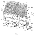
- the first subpart PP2 1 may comprise a rear face FR provided with four pins or fixing bolts BF (two upper and two lower).
- the second subpart PP2 2 may comprise, on the one hand, on its front face FV two hooks CF intended to allow the maintenance of its lower part on a lower cross member of the protective partition CP2, and, d on the other hand, on its rear face FR four holes or slots TF intended (s) to accommodate the heads of the four pins or fixing bolts BF once it has been manually returned by 180 °.
- a rotation lock latch LV mounted for rotation and intended to immobilize the upper part of the second sub-part. PP2 part 2 when the latter (PP2 2 ) is in a position that prohibits the passage of a load end to the passenger seat (s) folded or retracted. This position is that which is illustrated on the figures 1 and 4 .
- the lock latch LV must be rotated about 1 ⁇ 4 turn in order to release the upper part of the second subpart PP2 2 , and then the latter must be pulled ( PP2 2 ) towards the rear of the vehicle and slightly upwards to disengage its hooks CF from the lower cross member, then the second subpart PP2 2 must be turned 180 ° so that its rear face is placed facing the front rear of the first subpart PP2 1 , then must be pressed the second subpart PP2 2 against the first subpart PP2 1 taking care to penetrate the heads of the pins or bolts BF in the corresponding holes TF for the second subpart PP2 2 is suspended on the first subpart PP2 1 . It should be noted that instead of suspending the second subpart PP2 2 on the first subpart PP2 1 , it is possible to place it on the floor PL of the vehicle or to store it outside the vehicle.
- the second sub-part PP2 2 is adapted to translate substantially parallel to the first subpart PP2 1 .
- the protective partition CP2 may comprise two crosspieces (an intermediate TP and a lower one) defining slides in which upper and lower parts of the second subpart PP2 2 may slide.
- this second subpart PP2 2 advantageously defines a removable or sliding door (transversely) intended, when it is moved, to allow the passage through the protective partition CP2 of an end of an object having a large extension in the longitudinal direction X, once the back of the passenger seat (s) folded or once the passenger seat (s) retracted.
- a vehicle can be equipped with a protection device of great simplicity, firmly installed in the vehicle, allowing the longitudinal translations of the front seats, including independently of one another, and not requiring no intervention by the user (because the translation of the seat automatically causes a change of position of the associated protective partition).
- this protection device can be used to modulate the storage space while continuing to provide protection for the driver when it has at least one transverse sliding sub-portion.
Description
L'invention concerne les véhicules automobiles et utilitaires, et plus précisément certains dispositifs de protection qui sont installés dans les habitacles de tels véhicules et qui sont destinés à protéger les sièges conducteur et passager(s) avant situés dans le rang un.The invention relates to motor vehicles and utilities, and more specifically some protection devices that are installed in the interiors of such vehicles and which are intended to protect the driver and front passenger seats (s) located in the rank one.
Certains véhicules (automobiles et) utilitaires comprennent un habitacle délimité notamment par un plancher sur lequel sont installés des sièges conducteur et passager(s) avant qui doivent être protégés par un dispositif de protection (ou « d'arrêt de charge ») afin que les objets installés temporairement derrière eux ne viennent pas heurter leur face arrière, ce qui pourrait les endommager, voire blesser les passagers qu'ils accueillent.Certain vehicles (automobiles and) utilities include a passenger compartment defined in particular by a floor on which are installed driver and front passenger seats (s) which must be protected by a protective device (or "stop load") so that Temporarily installed objects behind them do not hit their rear face, which could damage them or even hurt the passengers they welcome.
Ce dispositif de protection comprend généralement une cloison de protection comportant une plaque rigide, ainsi qu'éventuellement une grille dans une partie supérieure. Cette cloison de protection est généralement solidarisée fixement à la structure du véhicule (et plus précisément au plancher et au toit (ou pavillon) et/ou aux cloisons latérales), juste derrière la face arrière des sièges avant, ce qui limite leur possibilité de translation longitudinale, voire interdit une telle translation longitudinale.This protection device generally comprises a protective partition comprising a rigid plate, and possibly a grid in an upper part. This protective partition is generally solidly attached to the vehicle structure (and more precisely to the floor and roof (or roof) and / or the side walls), just behind the rear face of the front seats, which limits their possibility of translation. longitudinal, or even prohibited such a longitudinal translation.
Afin de permettre une translation longitudinale des sièges par rapport à des paires de glissières solidarisées fixement sur le plancher, il est possible de solidariser le dispositif de protection aux sièges, et plus précisément à leurs assises, et non pas à la structure du véhicule. Mais cela n'est pas optimal en termes de protection car des objets chargés peuvent enfoncer la partie supérieure de la cloison de protection et éventuellement passer entre cette dernière et le toit (ou pavillon).To allow a longitudinal translation of the seats relative to pairs of rails fixedly secured to the floor, it is possible to secure the protective device to the seats, and more precisely to their seat, and not to the vehicle structure. But this is not optimal in terms of protection because charged objects can push the upper part of the protective partition and possibly pass between the latter and the roof (or pavilion).
Des dispositifs de protection plus sophistiqués ont également été proposés. Mais ils comprennent une cinématique qui s'avère généralement complexe à comprendre et/ou à utiliser pour l'usager, et/ou nécessitent un retrait (ou escamotage) du siège passager pour permettre un entraînement en rotation sur 90°, autour d'un axe vertical, de la cloison de protection, et/ou ils s'avèrent difficiles à installer dans l'habitacle (notamment du fait de la présence des paires de glissières), et/ou ils n'offrent pas de modularité (notamment du fait qu'ils ne permettent pas l'utilisation de l'espace avant libre offert par le rabattement du dossier du siège passager avant), et/ou ils ne permettent pas une optimisation de l'espace avant libre offert par le rabattement du dossier du siège passager avant.More sophisticated protection devices have also been proposed. But they include a kinematics that is generally complex to understand and / or use for the user, and / or require a withdrawal (or retraction) of the passenger seat to allow a 90 ° rotation drive, around a vertical axis, the protective partition, and / or they are difficult to install in the passenger compartment (in particular because of the presence of the pairs of slides), and / or they do not offer modularity (in particular because that they do not allow the use of space before free offered by folding the backrest of the front passenger seat), and / or they do not allow an optimization of the free front space offered by folding the backrest of the front passenger seat.
Le document
L'invention a donc notamment pour but d'améliorer la situation.The invention is therefore particularly intended to improve the situation.
Elle propose notamment à cet effet un dispositif de protection destiné à être associé à des sièges conducteur et passager(s) comprenant chacun une paire de brancards d'assise montée en translation sur une paire de glissières solidarisée à un plancher d'un véhicule utilitaire, et comprenant deux cloisons de protection destinées à être installées respectivement derrière les sièges conducteur et passager(s).It proposes for this purpose a protective device intended to be associated with driver and passenger seats (s) each comprising a pair of seat stretchers mounted in translation on a pair of rails secured to a floor of a commercial vehicle, and comprising two protective partitions intended to be installed respectively behind the driver and passenger seats (s).
Ce dispositif se caractérise par le fait :
- qu'il comprend deux paires de bielles comprenant des extrémités inférieures, destinées à être solidarisées à rotation respectivement aux brancards d'assise d'une paire associée, et des extrémités supérieures, et
- que chacune de ses cloisons de protection comprend une partie inférieure, couplée aux extrémités supérieures des bielles d'une paire associée, et une partie supérieure, destinée à être solidarisée à rotation à une partie d'un toit du véhicule, de sorte qu'elle puisse être entraînée en rotation par rapport à cette partie du toit en cas de translation de la paire de brancards d'assise associée par rapport à la paire de glissières correspondante.
- it comprises two pairs of connecting rods comprising lower ends, intended to be fixed respectively to rotation to the seat stretchers of an associated pair, and upper ends, and
- each of its protective partitions comprises a lower part, coupled to the upper ends of the connecting rods of an associated pair, and an upper part, intended to be rotatably fastened to a part of a roof of the vehicle, so that may be rotated relative to this part of the roof in the event of translation of the pair of associated seat stretchers relative to the corresponding pair of slides.
On dispose ainsi d'un dispositif de protection très simple qui ne gêne pas les translations longitudinales des sièges avant, y compris indépendamment l'un de l'autre, et ne nécessite aucune intervention de l'usager.This provides a very simple protection device that does not interfere longitudinal translations of the front seats, including independently of each other, and requires no intervention of the user.
Le dispositif selon l'invention peut comporter d'autres caractéristiques qui peuvent être prises séparément ou en combinaison, et notamment :
- la partie supérieure de l'une au moins des cloisons de protection peut comprendre une grille fixe ;
- la partie inférieure de chaque cloison de protection peut comprendre une paroi pleine ;
- ➢ la cloison de protection qui est destinée à être couplée au siège conducteur peut comprendre une paroi pleine fixe ;
- ➢ la cloison de protection qui est destinée à être couplée au siège passager(s) peut comprendre une paroi pleine comportant une première sous-partie fixe et une seconde sous-partie propre à se translater sensiblement parallèlement à la première sous-partie. En variante, la cloison de protection qui est destinée à être couplée au siège passager(s) peut comprendre une paroi pleine comportant une première sous-partie fixe et une seconde sous-partie amovible et propre à être solidarisée à la première sous-partie après avoir été retournée ;
- la partie supérieure de chaque cloison de protection peut comprendre une sous-partie d'au moins une charnière, destinée à être solidarisée à rotation à une sous-partie complémentaire de cette même charnière, qui est solidarisée fixement à une traverse définissant la partie du toit ;
- la partie inférieure de chaque cloison de protection peut comprendre deux pattes de fixation solidarisées à rotation respectivement aux extrémités supérieures des bielles de la paire associée.
- the upper part of at least one of the protective partitions may comprise a fixed grid;
- the lower part of each protective partition may comprise a solid wall;
- ➢ the protective partition which is intended to be coupled to the driver's seat may comprise a fixed solid wall;
- ➢ The protective partition which is intended to be coupled to the passenger seat (s) may comprise a solid wall having a first fixed sub-part and a second sub-part adapted to translate substantially parallel to the first subpart. Alternatively, the protective partition which is intended to be coupled to the passenger seat (s) may comprise a solid wall having a first fixed sub-part and a second removable subpart and adapted to be secured to the first subpart after have been returned;
- the upper part of each protective partition may comprise a sub-part of at least one hinge, designed to be rotatably connected to a complementary sub-part of the same hinge, which is fixedly attached to a cross-member defining the part of the roof ;
- the lower part of each protective partition may comprise two fixing lugs secured to rotation respectively to the upper ends of the rods of the associated pair.
L'invention propose également un véhicule utilitaire comprenant un toit, un plancher sur lequel sont solidarisées fixement deux paires de glissières auxquelles sont couplées en translation respectivement deux paires de brancards d'assise de sièges conducteur et passager(s), et un dispositif de protection du type de celui présenté ci-avant et solidarisé à rotation aux paires de brancards d'assise et à une partie du toit.The invention also proposes a utility vehicle comprising a roof, a floor on which two pairs of rails are fixedly secured to which are coupled in translation respectively two pairs of seat stretchers of driver and passenger seats (s), and a protective device of the type shown above and rotatably secured to the pairs of stretchers and a portion of the roof.
D'autres caractéristiques et avantages de l'invention apparaîtront à l'examen de la description détaillée ci-après, et des dessins annexés (obtenus en CAO/DAO, d'où le caractère apparemment discontinu de certaines lignes), sur lesquels :
- la
figure 1 illustre schématiquement, dans une vue en perspective (du côté avant), un exemple de réalisation d'un dispositif de protection selon l'invention solidarisé à rotation à des paires de glissières de sièges avant et à une partie d'un toit d'un véhicule utilitaire, - la
figure 2 illustre schématiquement, dans une vue en perspective (du côté avant), une traverse de toit sur laquelle est montée à rotation la partie supérieure du dispositif de protection de lafigure 1 , - la
figure 3 illustre schématiquement, dans une vue de côté, le dispositif de protection de lafigure 1 avec ses deux cloisons de protection placées dans deux positions différentes du fait du placement des paires de brancards d'assise dans deux positions longitudinales différentes, et - la
figure 4 illustre schématiquement, dans une vue en perspective (du côté arrière), le dispositif de protection de lafigure 1 au début du déplacement de la seconde sous-partie de la paroi pleine de sa paroi de protection destinée à être couplée au siège passager(s).
- the
figure 1 illustrates schematically, in a perspective view (the front side), an exemplary embodiment of a protection device according to the invention rotationally secured to pairs of front seat rails and a part of a roof of a commercial vehicle, - the
figure 2 schematically illustrates, in a perspective view (from the front side), a roof crossbar on which is rotatably mounted the upper part of the protection device of thefigure 1 , - the
figure 3 schematically illustrates, in a side view, the device of protection offigure 1 with its two protective partitions placed in two different positions due to the placement of the pairs of seat stretchers in two different longitudinal positions, and - the
figure 4 schematically illustrates, in a perspective view (from the rear side), the protective device of thefigure 1 at the beginning of the displacement of the second subpart of the solid wall of its protective wall intended to be coupled to the passenger seat (s).
On a schématiquement représenté sur les
Sur les figures, la direction X est la direction longitudinale du véhicule, laquelle est sensiblement parallèle aux côtés latéraux qui comportent les portes latérales (ou portières), la direction Y est la direction transversale du véhicule, laquelle est perpendiculaire à la direction longitudinale X et aux côtés latéraux, et la direction Z est la direction verticale du véhicule, laquelle est sensiblement perpendiculaire aux directions longitudinale X et transversale Y.In the figures, the direction X is the longitudinal direction of the vehicle, which is substantially parallel to the lateral sides which comprise the side doors (or doors), the direction Y is the transverse direction of the vehicle, which is perpendicular to the longitudinal direction X and at the lateral sides, and the direction Z is the vertical direction of the vehicle, which is substantially perpendicular to the longitudinal X and transverse Y directions.
On considère dans ce qui suit, à titre d'exemple non limitatif, que le véhicule automobile et utilitaire est un fourgon, éventuellement de type dit K1 ou K2. Mais l'invention n'est pas limitée à ce type de véhicule automobile et utilitaire. Elle concerne en effet tout type de véhicule automobile et utilitaire comportant au moins un premier rang (avant) de sièges, dont l'un est dédié à l'accueil d'un conducteur et au moins un autre est dédié à l'accueil d'au moins un passager.In the following, by way of nonlimiting example, the motor vehicle and utility vehicle is considered to be a van, possibly of the so-called K1 or K2 type. But the invention is not limited to this type of motor vehicle and utility. It concerns indeed any type of motor vehicle and utility comprising at least a first row (front) of seats, one of which is dedicated to the reception of a driver and at least one other is dedicated to the reception of at least one passenger.
Le véhicule (automobile et utilitaire) étant ici un fourgon, il ne comprend dans son habitacle qu'un unique rang de sièges. Mais il pourrait comporter au moins deux rangs de sièges (dont un avant).The vehicle (automobile and utility) being here a van, it understands in its cockpit only one row of seats. But it could have at least two rows of seats (including one front).
Par ailleurs, dans l'exemple non limitatif illustré sur la
On notera que le rang un pourrait comporter un ou deux sièges passager de type monoplace.It should be noted that the rank one could comprise one or two single-seat passenger seats.
Chaque siège comprend un dossier et une assise, éventuellement solidarisés l'un à l'autre. Chaque assise comporte une armature solidarisée à une paire de brancards d'assise BAj qui est montée en translation longitudinale (suivant X) sur une paire de glissière GLj solidarisée fixement sur le plancher PL du véhicule. Chaque dossier est de préférence monté à rotation autour d'au moins un axe sensiblement parallèle à la direction transversale Y et éventuellement couplé à l'armature d'assise.Each seat includes a backrest and a seat, possibly joined to each other. Each seat comprises a frame secured to a pair of seat stretchers BAj which is mounted in longitudinal translation (along X) on a pair of slide GLj fixedly secured to the floor PL of the vehicle. Each backrest is preferably rotatably mounted about at least one axis substantially parallel to the transverse direction Y and possibly coupled to the seat frame.
Comme illustré sur la
Les deux cloisons de protection CPj sont destinées à être installées respectivement derrière le siège conducteur et le siège passager(s), et donc à être respectivement associées à ces sièges et à leurs paires de glissières GLj correspondantes. Par ailleurs, chaque cloison de protection CPj comprend une partie supérieure et une partie inférieure.The two CPj protective partitions are intended to be installed respectively behind the driver's seat and the passenger seat (s), and therefore to be respectively associated with these seats and their pairs of corresponding GLj rails. Moreover, each protective partition CPj comprises an upper part and a lower part.
Les deux bielles BCj de chaque paire comprennent des extrémités inférieures, qui sont destinées à être solidarisées à rotation respectivement à des parties arrière de brancards d'assise BAj de la paire associée, et des extrémités supérieures, qui sont solidarisées à rotation respectivement aux parties inférieures des cloisons de protection CPj associées.The two connecting rods BCj of each pair comprise lower ends, which are intended to be rotatably secured respectively to rear parts of seat stretchers BAj of the associated pair, and upper ends, which are rotationally secured respectively to the lower parts. associated protective partitions CPj.
A cet effet, la partie inférieure de chaque cloison de protection CPj peut, par exemple, comprendre deux pattes de fixation PF qui sont solidarisées à rotation respectivement aux extrémités supérieures des bielles BCj de la paire associée, comme illustré non limitativement sur les
La partie supérieure de chaque cloison de protection CPj est destinée à être solidarisée à rotation à une partie TT du toit du véhicule. Cette rotation se fait suivant une direction qui est sensiblement parallèle à la direction transversale Y, comme illustré sur la
Ainsi, chaque cloison de protection CPj peut être entraînée en rotation par rapport à la partie TT du toit lorsque la paire de brancards d'assise BAj associée (et donc le siège associé) est translaté(e) par rapport à la paire de glissières GLj correspondante. On comprendra en effet que lorsque l'on translate un siège par rapport à la paire de glissières GLj associée, la partie inférieure de la cloison de protection CPj qui est couplée à ce siège est également entraînée. Mais du fait que ce dernier couplage se fait via des bielles BCj dont les extrémités supérieure et inférieure sont montées à rotation, cet entraînement se traduit par une rotation par rapport au toit.Thus, each protective partition CPj can be driven in rotation relative to the part TT of the roof when the pair of seat stretchers BAj associated (and therefore the associated seat) is translated relative to the pair of slides GLj corresponding. It will be understood that when a seat is translated relative to the pair of slides GLj associated, the lower portion of the protective partition CPj which is coupled to this seat is also driven. But because the latter coupling is via BCj connecting rods whose upper and lower ends are rotatably mounted, this drive results in a rotation relative to the roof.
On a schématiquement illustré sur la
Comme illustré non limitativement sur la
On notera également qu'afin de faciliter la visibilité vers l'arrière du véhicule, il est avantageux, comme illustré non limitativement sur les
Dans l'exemple non limitatif illustré sur les
On notera également, comme illustré non limitativement sur la
Egalement comme illustré non limitativement sur la
Egalement comme illustré non limitativement sur les
Dans l'exemple non limitatif illustré sur les
Dans une variante de réalisation non représentée, la seconde sous-partie PP22 est propre à se translater sensiblement parallèlement à la première sous-partie PP21. A cet effet, la cloison de protection CP2 peut comprendre deux traverses (une intermédiaire TP et une inférieure) définissant des glissières dans lesquelles peuvent coulisser des parties supérieure et inférieure de la seconde sous-partie PP22.In a variant embodiment, not shown, the second sub-part PP2 2 is adapted to translate substantially parallel to the first subpart PP2 1 . For this purpose, the protective partition CP2 may comprise two crosspieces (an intermediate TP and a lower one) defining slides in which upper and lower parts of the second subpart PP2 2 may slide.
On comprendra que cette seconde sous-partie PP22 définit avantageusement une trappe amovible ou coulissante (transversalement) destinée, lorsqu'elle est déplacée, à permettre le passage au travers de la cloison de protection CP2 d'une extrémité d'un objet présentant une grande extension suivant la direction longitudinale X, une fois le dossier du siège passager(s) rabattu ou une fois le siège passager(s) escamoté.It will be understood that this second subpart PP2 2 advantageously defines a removable or sliding door (transversely) intended, when it is moved, to allow the passage through the protective partition CP2 of an end of an object having a large extension in the longitudinal direction X, once the back of the passenger seat (s) folded or once the passenger seat (s) retracted.
Grâce à l'invention, un véhicule peut être équipé d'un dispositif de protection d'une grande simplicité, solidement installé dans le véhicule, permettant les translations longitudinales des sièges avant, y compris indépendamment l'un de l'autre, et ne nécessitant aucune intervention de l'usager (du fait que la translation du siège provoque automatiquement un changement de position de la cloison de protection associée). De plus, ce dispositif de protection peut permettre de moduler l'espace de rangement tout en continuant d'assurer la protection du conducteur lorsqu'il possède au moins une sous-partie coulissante transversalement.Thanks to the invention, a vehicle can be equipped with a protection device of great simplicity, firmly installed in the vehicle, allowing the longitudinal translations of the front seats, including independently of one another, and not requiring no intervention by the user (because the translation of the seat automatically causes a change of position of the associated protective partition). In addition, this protection device can be used to modulate the storage space while continuing to provide protection for the driver when it has at least one transverse sliding sub-portion.
Claims (9)
- Protection device (D) for the driver and passenger seats including for each one a pair of seat bar frames (BAj) mounted in a moveable manner on a pair of slide rails (GLj) solidly fixed to the floor (PL) of a utility vehicle, the said device (D) comprises two protective panels (CPj) destined to be installed respectively behind the driver and passenger seats, characterised in that they include two pairs of rods (BCj) including lower extremities, destined to be rotationally fixed respectively to the associated pair of seat bar frames (BAj), and the upper extremities, in that each of the said protective panels (CPj) includes a lower part, destined to be solidly fixed in rotation to the upper extremities of the rods (BCj) of an associated pair, and an upper part, destined to be solidly fixed in rotation to a part (TT) of the vehicle roof, so that this may be rotated compared to the said part of the roof (TT) in case of movement of the pair of associated seat bar frames(BAj) relative to the corresponding pair of slide rails (GLj).
- Process according to claim 1 characterised in that the said upper part of at least one of the said protective panels (CPj) includes a fixed grill (GRj).
- Device according to one of the claims 1 and 2, characterised in that the said lower part of each protective panel (CPj) includes a full panel (PPj).
- Device according to claim 3, characterised in that the protective panel (CP1) destined to be connected to the driver's seat includes a fixed full panel (PPj).
- Device according to one of the claims 3 and 4, characterised in that the protective panel (CP2) destined to be connected to the said passenger seat, includes a full panel (PP2) including a first fixed sub-section (PP21) and a second sub-section (PP22) able to move essentially parallel to the aforementioned first sub-section (PP21).
- Device according to one of the claims 3 and 4, characterised in that the protective panel (CP2) destined to be connected to the said passenger seat includes a full panel (PP2) including a first fixed sub-section (PP21) and a second moveable sub-section (PP22) able to be solidly fixed to the said first sub-section (PP21) after having been turned back.
- Device according to one of the claims 1 to 6 characterised in that the said upper part of each protective panel (CPj) includes a sub-part of at least one hinge (CH), destined to be rotationally solid to a complementary sub-part of this same hinge (CH), which is solidly fixed to a cross piece defining the said part (TT) of the roof.
- Device according to one of the claims 1 to 7 characterised in that the said lower part of each protective panel (CPj) includes two fixing pads (PF) rotationally fixed respectively to the upper extremities of the associated pair of rods (BCj).
- Utility vehicle comprising a roof and a floor (PL) to which are solidly fixed two pairs of slide rails (GLj) to which are connected respectively two pairs of seat bar frames (BAj) of the driver and passenger seats, characterised in that in addition a protective device (D) is included according to one of the precedent claims, solidly fixed in rotation to the said two pairs of seat bar frames (BAj) and to a part of the said roof (TT).
Applications Claiming Priority (1)
| Application Number | Priority Date | Filing Date | Title |
|---|---|---|---|
| FR1451641A FR3018054B1 (en) | 2014-02-28 | 2014-02-28 | PROTECTIVE DEVICE FOR SLIDING SEATS OF A UTILITY VEHICLE |
Publications (2)
| Publication Number | Publication Date |
|---|---|
| EP2913231A1 EP2913231A1 (en) | 2015-09-02 |
| EP2913231B1 true EP2913231B1 (en) | 2016-11-30 |
Family
ID=50976828
Family Applications (1)
| Application Number | Title | Priority Date | Filing Date |
|---|---|---|---|
| EP15156044.8A Active EP2913231B1 (en) | 2014-02-28 | 2015-02-23 | Protection device for sliding seats of a commercial vehicle |
Country Status (3)
| Country | Link |
|---|---|
| EP (1) | EP2913231B1 (en) |
| ES (1) | ES2606700T3 (en) |
| FR (1) | FR3018054B1 (en) |
Families Citing this family (6)
| Publication number | Priority date | Publication date | Assignee | Title |
|---|---|---|---|---|
| DE102016104794A1 (en) * | 2016-03-15 | 2017-09-21 | Airbus Operations Gmbh | Partition module for a cabin of a vehicle for the optical and mechanical separation of different cabin areas |
| FR3079480B1 (en) * | 2018-03-29 | 2020-10-16 | Renault Sas | VEHICLE PARTITIONING DEVICE |
| EP3524476B1 (en) * | 2018-02-07 | 2022-06-01 | Renault s.a.s | Partitioning device for a vehicle |
| FR3085919B1 (en) * | 2018-09-18 | 2020-10-23 | Psa Automobiles Sa | GUIDANCE DEVICE FOR UTILITY VEHICLE AND ASSEMBLY PROCESS |
| FR3092051B1 (en) * | 2019-01-29 | 2021-01-01 | Psa Automobiles Sa | PROTECTIVE DEVICE FOR A VEHICLE, WITH A PROTECTION GRILLE INCLINED TO THE REAR |
| FR3094303A1 (en) * | 2019-03-26 | 2020-10-02 | Psa Automobiles Sa | UTILITY VEHICLE INCLUDING A SEPARATION BULKHEAD |
Family Cites Families (4)
| Publication number | Priority date | Publication date | Assignee | Title |
|---|---|---|---|---|
| FR2876637B1 (en) * | 2004-10-14 | 2007-02-02 | Productions Sa Sa B V | REMOVABLE SEPARATION PANEL FOR UTILITY VEHICLE, UTILITY VEHICLE EQUIPPED WITH SUCH A CLOISON |
| GB2459703B (en) * | 2008-05-02 | 2012-04-11 | Nissan Motor Mfg Uk Ltd | Vehicle with adjustable partition wall |
| EP2300274A4 (en) * | 2008-06-12 | 2012-04-04 | Dan Holmberg | Partition device |
| US7806452B2 (en) * | 2009-02-09 | 2010-10-05 | Xtreme Metal Fab, Inc. | Adjustable security partition for a vehicle |
-
2014
- 2014-02-28 FR FR1451641A patent/FR3018054B1/en active Active
-
2015
- 2015-02-23 EP EP15156044.8A patent/EP2913231B1/en active Active
- 2015-02-23 ES ES15156044.8T patent/ES2606700T3/en active Active
Non-Patent Citations (1)
| Title |
|---|
| None * |
Also Published As
| Publication number | Publication date |
|---|---|
| FR3018054B1 (en) | 2016-02-19 |
| EP2913231A1 (en) | 2015-09-02 |
| ES2606700T3 (en) | 2017-03-27 |
| FR3018054A1 (en) | 2015-09-04 |
Similar Documents
| Publication | Publication Date | Title |
|---|---|---|
| EP2913231B1 (en) | Protection device for sliding seats of a commercial vehicle | |
| EP2569216B1 (en) | Seat base having a controlled and optimised path and associated seat | |
| FR3000017A1 (en) | FRONT AIRCRAFT TIP WITH INTEGRATED COCKPIT MODULES AND AIRCRAFT SLEEVE | |
| FR3021272A1 (en) | PROTECTIVE DEVICE WITH ROTATING PROTECTION PARTS AND LATERAL PROTECTION MEANS FOR SLIDING SEATS OF A UTILITY VEHICLE | |
| EP2173642B1 (en) | Baggage container | |
| EP3038862B1 (en) | Sliding partitioning arrangement inside a vehicle. | |
| EP3197722B1 (en) | Arrangement of a floor inside a luggage compartment of a motor vehicle comprising retractable seats | |
| FR3010018A1 (en) | ARRANGEMENT OF A SLIDING PARTITION WITHIN A VEHICLE WITH AN OPENING | |
| FR3021273A1 (en) | PROTECTIVE DEVICE WITH ROTATION-FITTED PROTECTIVE PROTECTION PARTS AND EXTENSIBLE AND LATERAL PROTECTION MEANS FOR SLIDING SEATS OF A UTILITY VEHICLE | |
| WO2011131875A1 (en) | Device for mounting a seat, designed for controlling the volume of the stowage space under said seat | |
| FR3034731A1 (en) | MOBILE PARTITIONING DEVICE WITHIN THE VEHICLE OF A VEHICLE | |
| EP2956332A1 (en) | Attachment of a detachable and stowable seat to the floor of a vehicle | |
| EP2830930A1 (en) | Partially retractable steering column and instrument panel support crossmember system for vehicle and mounting thereof | |
| EP3710311B1 (en) | Interior assembly for supporting loads that is arranged in the upper interior part of the vehicle | |
| EP2763885B1 (en) | Motor vehicle dashboard crossmember arrangement and vehicle comprising such an arrangement | |
| EP3164294B1 (en) | Seat for motor vehicle and mounting method | |
| WO2015158974A1 (en) | Motor vehicle fitted with more lightweight rear bench seat | |
| EP2858885B1 (en) | Device for installing a seat or set of seats in the same row in a vehicle, and associated method | |
| FR2993519A1 (en) | Flexible seat for utility car, has base mounted integral with set of side walls that is movable in translation with regard to set of side parts, where set of side parts is intended to be mounted on floor of vehicle | |
| FR2900878A1 (en) | RECOVERABLE SEAT IN PARTICULAR OF ROW 3 | |
| EP2814689B1 (en) | Device for protecting a motor vehicle frameless rear seat | |
| FR2767755A1 (en) | DISCOVERABLE MOTOR VEHICLE | |
| FR3049561A1 (en) | EDUCATIONAL VEHICLE FOR ROAD RELIEF SERVICES | |
| EP3917808A1 (en) | Protection device for a vehicle, with protection grating inclined towards the rear | |
| FR2979861A1 (en) | SECTIONAL FOLDING SEAT DEVICE FOR VEHICLE CABINET |
Legal Events
| Date | Code | Title | Description |
|---|---|---|---|
| PUAI | Public reference made under article 153(3) epc to a published international application that has entered the european phase |
Free format text: ORIGINAL CODE: 0009012 |
|
| AK | Designated contracting states |
Kind code of ref document: A1 Designated state(s): AL AT BE BG CH CY CZ DE DK EE ES FI FR GB GR HR HU IE IS IT LI LT LU LV MC MK MT NL NO PL PT RO RS SE SI SK SM TR |
|
| AX | Request for extension of the european patent |
Extension state: BA ME |
|
| 17P | Request for examination filed |
Effective date: 20160223 |
|
| RBV | Designated contracting states (corrected) |
Designated state(s): AL AT BE BG CH CY CZ DE DK EE ES FI FR GB GR HR HU IE IS IT LI LT LU LV MC MK MT NL NO PL PT RO RS SE SI SK SM TR |
|
| GRAP | Despatch of communication of intention to grant a patent |
Free format text: ORIGINAL CODE: EPIDOSNIGR1 |
|
| INTG | Intention to grant announced |
Effective date: 20160701 |
|
| RIN1 | Information on inventor provided before grant (corrected) |
Inventor name: COUNAGO GONZALEZ, MARCOS Inventor name: DUVIVIER, ARNAUD M. Inventor name: BAUVINEAU, LAURENT M. Inventor name: VAZQUEY SABARIEGO, JOSE IGNACIO Inventor name: SA COUTINHO, LIONEL Inventor name: HAYAT, DAVID |
|
| GRAS | Grant fee paid |
Free format text: ORIGINAL CODE: EPIDOSNIGR3 |
|
| GRAA | (expected) grant |
Free format text: ORIGINAL CODE: 0009210 |
|
| AK | Designated contracting states |
Kind code of ref document: B1 Designated state(s): AL AT BE BG CH CY CZ DE DK EE ES FI FR GB GR HR HU IE IS IT LI LT LU LV MC MK MT NL NO PL PT RO RS SE SI SK SM TR |
|
| REG | Reference to a national code |
Ref country code: CH Ref legal event code: EP Ref country code: GB Ref legal event code: FG4D Free format text: NOT ENGLISH |
|
| REG | Reference to a national code |
Ref country code: AT Ref legal event code: REF Ref document number: 849473 Country of ref document: AT Kind code of ref document: T Effective date: 20161215 |
|
| REG | Reference to a national code |
Ref country code: IE Ref legal event code: FG4D Free format text: LANGUAGE OF EP DOCUMENT: FRENCH |
|
| REG | Reference to a national code |
Ref country code: DE Ref legal event code: R096 Ref document number: 602015000823 Country of ref document: DE |
|
| REG | Reference to a national code |
Ref country code: FR Ref legal event code: PLFP Year of fee payment: 3 |
|
| PG25 | Lapsed in a contracting state [announced via postgrant information from national office to epo] |
Ref country code: LV Free format text: LAPSE BECAUSE OF FAILURE TO SUBMIT A TRANSLATION OF THE DESCRIPTION OR TO PAY THE FEE WITHIN THE PRESCRIBED TIME-LIMIT Effective date: 20161130 |
|
| REG | Reference to a national code |
Ref country code: LT Ref legal event code: MG4D |
|
| REG | Reference to a national code |
Ref country code: NL Ref legal event code: MP Effective date: 20161130 |
|
| REG | Reference to a national code |
Ref country code: AT Ref legal event code: MK05 Ref document number: 849473 Country of ref document: AT Kind code of ref document: T Effective date: 20161130 |
|
| PG25 | Lapsed in a contracting state [announced via postgrant information from national office to epo] |
Ref country code: SE Free format text: LAPSE BECAUSE OF FAILURE TO SUBMIT A TRANSLATION OF THE DESCRIPTION OR TO PAY THE FEE WITHIN THE PRESCRIBED TIME-LIMIT Effective date: 20161130 Ref country code: LT Free format text: LAPSE BECAUSE OF FAILURE TO SUBMIT A TRANSLATION OF THE DESCRIPTION OR TO PAY THE FEE WITHIN THE PRESCRIBED TIME-LIMIT Effective date: 20161130 Ref country code: GR Free format text: LAPSE BECAUSE OF FAILURE TO SUBMIT A TRANSLATION OF THE DESCRIPTION OR TO PAY THE FEE WITHIN THE PRESCRIBED TIME-LIMIT Effective date: 20170301 Ref country code: NO Free format text: LAPSE BECAUSE OF FAILURE TO SUBMIT A TRANSLATION OF THE DESCRIPTION OR TO PAY THE FEE WITHIN THE PRESCRIBED TIME-LIMIT Effective date: 20170228 |
|
| PG25 | Lapsed in a contracting state [announced via postgrant information from national office to epo] |
Ref country code: FI Free format text: LAPSE BECAUSE OF FAILURE TO SUBMIT A TRANSLATION OF THE DESCRIPTION OR TO PAY THE FEE WITHIN THE PRESCRIBED TIME-LIMIT Effective date: 20161130 Ref country code: RS Free format text: LAPSE BECAUSE OF FAILURE TO SUBMIT A TRANSLATION OF THE DESCRIPTION OR TO PAY THE FEE WITHIN THE PRESCRIBED TIME-LIMIT Effective date: 20161130 Ref country code: PL Free format text: LAPSE BECAUSE OF FAILURE TO SUBMIT A TRANSLATION OF THE DESCRIPTION OR TO PAY THE FEE WITHIN THE PRESCRIBED TIME-LIMIT Effective date: 20161130 Ref country code: HR Free format text: LAPSE BECAUSE OF FAILURE TO SUBMIT A TRANSLATION OF THE DESCRIPTION OR TO PAY THE FEE WITHIN THE PRESCRIBED TIME-LIMIT Effective date: 20161130 Ref country code: AT Free format text: LAPSE BECAUSE OF FAILURE TO SUBMIT A TRANSLATION OF THE DESCRIPTION OR TO PAY THE FEE WITHIN THE PRESCRIBED TIME-LIMIT Effective date: 20161130 Ref country code: PT Free format text: LAPSE BECAUSE OF FAILURE TO SUBMIT A TRANSLATION OF THE DESCRIPTION OR TO PAY THE FEE WITHIN THE PRESCRIBED TIME-LIMIT Effective date: 20170330 Ref country code: BE Free format text: LAPSE BECAUSE OF NON-PAYMENT OF DUE FEES Effective date: 20170228 |
|
| PG25 | Lapsed in a contracting state [announced via postgrant information from national office to epo] |
Ref country code: NL Free format text: LAPSE BECAUSE OF FAILURE TO SUBMIT A TRANSLATION OF THE DESCRIPTION OR TO PAY THE FEE WITHIN THE PRESCRIBED TIME-LIMIT Effective date: 20161130 |
|
| PG25 | Lapsed in a contracting state [announced via postgrant information from national office to epo] |
Ref country code: CZ Free format text: LAPSE BECAUSE OF FAILURE TO SUBMIT A TRANSLATION OF THE DESCRIPTION OR TO PAY THE FEE WITHIN THE PRESCRIBED TIME-LIMIT Effective date: 20161130 Ref country code: EE Free format text: LAPSE BECAUSE OF FAILURE TO SUBMIT A TRANSLATION OF THE DESCRIPTION OR TO PAY THE FEE WITHIN THE PRESCRIBED TIME-LIMIT Effective date: 20161130 Ref country code: DK Free format text: LAPSE BECAUSE OF FAILURE TO SUBMIT A TRANSLATION OF THE DESCRIPTION OR TO PAY THE FEE WITHIN THE PRESCRIBED TIME-LIMIT Effective date: 20161130 Ref country code: RO Free format text: LAPSE BECAUSE OF FAILURE TO SUBMIT A TRANSLATION OF THE DESCRIPTION OR TO PAY THE FEE WITHIN THE PRESCRIBED TIME-LIMIT Effective date: 20161130 Ref country code: SK Free format text: LAPSE BECAUSE OF FAILURE TO SUBMIT A TRANSLATION OF THE DESCRIPTION OR TO PAY THE FEE WITHIN THE PRESCRIBED TIME-LIMIT Effective date: 20161130 |
|
| RAP2 | Party data changed (patent owner data changed or rights of a patent transferred) |
Owner name: PSA AUTOMOBILES SA Owner name: GRUPO ANTOLIN-INGENIERIA SA |
|
| PG25 | Lapsed in a contracting state [announced via postgrant information from national office to epo] |
Ref country code: BG Free format text: LAPSE BECAUSE OF FAILURE TO SUBMIT A TRANSLATION OF THE DESCRIPTION OR TO PAY THE FEE WITHIN THE PRESCRIBED TIME-LIMIT Effective date: 20170228 Ref country code: IT Free format text: LAPSE BECAUSE OF FAILURE TO SUBMIT A TRANSLATION OF THE DESCRIPTION OR TO PAY THE FEE WITHIN THE PRESCRIBED TIME-LIMIT Effective date: 20161130 Ref country code: SM Free format text: LAPSE BECAUSE OF FAILURE TO SUBMIT A TRANSLATION OF THE DESCRIPTION OR TO PAY THE FEE WITHIN THE PRESCRIBED TIME-LIMIT Effective date: 20161130 |
|
| REG | Reference to a national code |
Ref country code: DE Ref legal event code: R097 Ref document number: 602015000823 Country of ref document: DE |
|
| PG25 | Lapsed in a contracting state [announced via postgrant information from national office to epo] |
Ref country code: MC Free format text: LAPSE BECAUSE OF FAILURE TO SUBMIT A TRANSLATION OF THE DESCRIPTION OR TO PAY THE FEE WITHIN THE PRESCRIBED TIME-LIMIT Effective date: 20161130 |
|
| PLBE | No opposition filed within time limit |
Free format text: ORIGINAL CODE: 0009261 |
|
| STAA | Information on the status of an ep patent application or granted ep patent |
Free format text: STATUS: NO OPPOSITION FILED WITHIN TIME LIMIT |
|
| 26N | No opposition filed |
Effective date: 20170831 |
|
| REG | Reference to a national code |
Ref country code: IE Ref legal event code: MM4A |
|
| PG25 | Lapsed in a contracting state [announced via postgrant information from national office to epo] |
Ref country code: SI Free format text: LAPSE BECAUSE OF FAILURE TO SUBMIT A TRANSLATION OF THE DESCRIPTION OR TO PAY THE FEE WITHIN THE PRESCRIBED TIME-LIMIT Effective date: 20161130 |
|
| PG25 | Lapsed in a contracting state [announced via postgrant information from national office to epo] |
Ref country code: LU Free format text: LAPSE BECAUSE OF NON-PAYMENT OF DUE FEES Effective date: 20170223 |
|
| REG | Reference to a national code |
Ref country code: FR Ref legal event code: PLFP Year of fee payment: 4 |
|
| REG | Reference to a national code |
Ref country code: BE Ref legal event code: MM Effective date: 20170228 |
|
| PG25 | Lapsed in a contracting state [announced via postgrant information from national office to epo] |
Ref country code: IE Free format text: LAPSE BECAUSE OF NON-PAYMENT OF DUE FEES Effective date: 20170223 |
|
| REG | Reference to a national code |
Ref country code: FR Ref legal event code: CA Effective date: 20180312 Ref country code: FR Ref legal event code: CD Owner name: PEUGEOT CITROEN AUTOMOBILES SA, FR Effective date: 20180312 Ref country code: FR Ref legal event code: CD Owner name: GRUPO ANTOLIN-INGENIERIA SA, ES Effective date: 20180312 |
|
| REG | Reference to a national code |
Ref country code: CH Ref legal event code: PL |
|
| PG25 | Lapsed in a contracting state [announced via postgrant information from national office to epo] |
Ref country code: MT Free format text: LAPSE BECAUSE OF FAILURE TO SUBMIT A TRANSLATION OF THE DESCRIPTION OR TO PAY THE FEE WITHIN THE PRESCRIBED TIME-LIMIT Effective date: 20161130 |
|
| PG25 | Lapsed in a contracting state [announced via postgrant information from national office to epo] |
Ref country code: CH Free format text: LAPSE BECAUSE OF NON-PAYMENT OF DUE FEES Effective date: 20180228 Ref country code: LI Free format text: LAPSE BECAUSE OF NON-PAYMENT OF DUE FEES Effective date: 20180228 |
|
| PG25 | Lapsed in a contracting state [announced via postgrant information from national office to epo] |
Ref country code: HU Free format text: LAPSE BECAUSE OF FAILURE TO SUBMIT A TRANSLATION OF THE DESCRIPTION OR TO PAY THE FEE WITHIN THE PRESCRIBED TIME-LIMIT; INVALID AB INITIO Effective date: 20150223 |
|
| PG25 | Lapsed in a contracting state [announced via postgrant information from national office to epo] |
Ref country code: CY Free format text: LAPSE BECAUSE OF FAILURE TO SUBMIT A TRANSLATION OF THE DESCRIPTION OR TO PAY THE FEE WITHIN THE PRESCRIBED TIME-LIMIT Effective date: 20161130 |
|
| PG25 | Lapsed in a contracting state [announced via postgrant information from national office to epo] |
Ref country code: MK Free format text: LAPSE BECAUSE OF FAILURE TO SUBMIT A TRANSLATION OF THE DESCRIPTION OR TO PAY THE FEE WITHIN THE PRESCRIBED TIME-LIMIT Effective date: 20161130 |
|
| PG25 | Lapsed in a contracting state [announced via postgrant information from national office to epo] |
Ref country code: TR Free format text: LAPSE BECAUSE OF FAILURE TO SUBMIT A TRANSLATION OF THE DESCRIPTION OR TO PAY THE FEE WITHIN THE PRESCRIBED TIME-LIMIT Effective date: 20161130 |
|
| PG25 | Lapsed in a contracting state [announced via postgrant information from national office to epo] |
Ref country code: AL Free format text: LAPSE BECAUSE OF FAILURE TO SUBMIT A TRANSLATION OF THE DESCRIPTION OR TO PAY THE FEE WITHIN THE PRESCRIBED TIME-LIMIT Effective date: 20161130 Ref country code: IS Free format text: LAPSE BECAUSE OF FAILURE TO SUBMIT A TRANSLATION OF THE DESCRIPTION OR TO PAY THE FEE WITHIN THE PRESCRIBED TIME-LIMIT Effective date: 20170330 |
|
| PGFP | Annual fee paid to national office [announced via postgrant information from national office to epo] |
Ref country code: FR Payment date: 20230119 Year of fee payment: 9 Ref country code: ES Payment date: 20230301 Year of fee payment: 9 |
|
| PGFP | Annual fee paid to national office [announced via postgrant information from national office to epo] |
Ref country code: GB Payment date: 20230120 Year of fee payment: 9 Ref country code: DE Payment date: 20230119 Year of fee payment: 9 |
|
| PGFP | Annual fee paid to national office [announced via postgrant information from national office to epo] |
Ref country code: ES Payment date: 20240301 Year of fee payment: 10 |
|
| PGFP | Annual fee paid to national office [announced via postgrant information from national office to epo] |
Ref country code: DE Payment date: 20240123 Year of fee payment: 10 Ref country code: GB Payment date: 20240123 Year of fee payment: 10 |