EP2913231B1 - Schutzvorrichtung für Schiebesitze eines Nutzfahrzeugs - Google Patents
Schutzvorrichtung für Schiebesitze eines Nutzfahrzeugs Download PDFInfo
- Publication number
- EP2913231B1 EP2913231B1 EP15156044.8A EP15156044A EP2913231B1 EP 2913231 B1 EP2913231 B1 EP 2913231B1 EP 15156044 A EP15156044 A EP 15156044A EP 2913231 B1 EP2913231 B1 EP 2913231B1
- Authority
- EP
- European Patent Office
- Prior art keywords
- protective
- sub
- seat
- fixed
- cpj
- Prior art date
- Legal status (The legal status is an assumption and is not a legal conclusion. Google has not performed a legal analysis and makes no representation as to the accuracy of the status listed.)
- Active
Links
- 230000001681 protective effect Effects 0.000 claims description 60
- 239000007787 solid Substances 0.000 claims description 12
- 230000000295 complement effect Effects 0.000 claims description 3
- 210000001364 upper extremity Anatomy 0.000 claims 3
- 210000003141 lower extremity Anatomy 0.000 claims 1
- 238000005192 partition Methods 0.000 description 43
- 238000013519 translation Methods 0.000 description 11
- 230000014616 translation Effects 0.000 description 11
- 230000008878 coupling Effects 0.000 description 2
- 238000010168 coupling process Methods 0.000 description 2
- 238000005859 coupling reaction Methods 0.000 description 2
- 238000004873 anchoring Methods 0.000 description 1
- 238000006073 displacement reaction Methods 0.000 description 1
- 238000012423 maintenance Methods 0.000 description 1
- 238000005457 optimization Methods 0.000 description 1
- 230000000007 visual effect Effects 0.000 description 1
Images


Classifications
-
- B—PERFORMING OPERATIONS; TRANSPORTING
- B60—VEHICLES IN GENERAL
- B60R—VEHICLES, VEHICLE FITTINGS, OR VEHICLE PARTS, NOT OTHERWISE PROVIDED FOR
- B60R21/00—Arrangements or fittings on vehicles for protecting or preventing injuries to occupants or pedestrians in case of accidents or other traffic risks
- B60R21/02—Occupant safety arrangements or fittings, e.g. crash pads
- B60R21/026—Rigid partitions inside vehicles, e.g. between passengers and load compartments
Definitions
- the invention relates to motor vehicles and utilities, and more specifically some protection devices that are installed in the interiors of such vehicles and which are intended to protect the driver and front passenger seats (s) located in the rank one.
- Certain vehicles automobiles and) utilities include a passenger compartment defined in particular by a floor on which are installed driver and front passenger seats (s) which must be protected by a protective device (or "stop load") so that Temporarily installed objects behind them do not hit their rear face, which could damage them or even hurt the passengers they welcome.
- This protection device generally comprises a protective partition comprising a rigid plate, and possibly a grid in an upper part.
- This protective partition is generally solidly attached to the vehicle structure (and more precisely to the floor and roof (or roof) and / or the side walls), just behind the rear face of the front seats, which limits their possibility of translation. longitudinal, or even prohibited such a longitudinal translation.
- More sophisticated protection devices have also been proposed. But they include a kinematics that is generally complex to understand and / or use for the user, and / or require a withdrawal (or retraction) of the passenger seat to allow a 90 ° rotation drive, around a vertical axis, the protective partition, and / or they are difficult to install in the passenger compartment (in particular because of the presence of the pairs of slides), and / or they do not offer modularity (in particular because that they do not allow the use of space before free offered by folding the backrest of the front passenger seat), and / or they do not allow an optimization of the free front space offered by folding the backrest of the front passenger seat.
- the invention is therefore particularly intended to improve the situation.
- a protective device intended to be associated with driver and passenger seats (s) each comprising a pair of seat stretchers mounted in translation on a pair of rails secured to a floor of a commercial vehicle, and comprising two protective partitions intended to be installed respectively behind the driver and passenger seats (s).
- This provides a very simple protection device that does not interfere longitudinal translations of the front seats, including independently of each other, and requires no intervention of the user.
- the invention also proposes a utility vehicle comprising a roof, a floor on which two pairs of rails are fixedly secured to which are coupled in translation respectively two pairs of seat stretchers of driver and passenger seats (s), and a protective device of the type shown above and rotatably secured to the pairs of stretchers and a portion of the roof.
- the direction X is the longitudinal direction of the vehicle, which is substantially parallel to the lateral sides which comprise the side doors (or doors)
- the direction Y is the transverse direction of the vehicle, which is perpendicular to the longitudinal direction X and at the lateral sides
- the direction Z is the vertical direction of the vehicle, which is substantially perpendicular to the longitudinal X and transverse Y directions.
- the motor vehicle and utility vehicle is considered to be a van, possibly of the so-called K1 or K2 type. But the invention is not limited to this type of motor vehicle and utility. It concerns indeed any type of motor vehicle and utility comprising at least a first row (front) of seats, one of which is dedicated to the reception of a driver and at least one other is dedicated to the reception of at least one passenger.
- the vehicle (automobile and utility) being here a van, it understands in its cockpit only one row of seats. But it could have at least two rows of seats (including one front).
- the single row includes only a driver seat (here placed on the left) and a passenger seat (possibly retractable, possibly two-seater (or seat), and here on the right).
- rank one could comprise one or two single-seat passenger seats.
- Each seat includes a backrest and a seat, possibly joined to each other.
- Each seat comprises a frame secured to a pair of seat stretchers BAj which is mounted in longitudinal translation (along X) on a pair of slide GLj fixedly secured to the floor PL of the vehicle.
- Each backrest is preferably rotatably mounted about at least one axis substantially parallel to the transverse direction Y and possibly coupled to the seat frame.
- a protection device (or “load stop”) D comprises at least two protective partitions CPj and two pairs of connecting rods BCj.
- each protective partition CPj comprises an upper part and a lower part.
- the two connecting rods BCj of each pair comprise lower ends, which are intended to be rotatably secured respectively to rear parts of seat stretchers BAj of the associated pair, and upper ends, which are rotationally secured respectively to the lower parts.
- associated protective partitions CPj are associated protective partitions CPj.
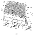
- each protective partition CPj may, for example, comprise two fixing lugs PF which are rotationally secured respectively to the upper ends of the connecting rods BCj of the associated pair, as shown in non-limiting manner on the figures 1 and 3 .
- This joining can be along axes substantially parallel to the transverse direction Y.
- each protective partition CPj is intended to be rotatably attached to a part TT of the roof of the vehicle. This rotation is in a direction that is substantially parallel to the transverse direction Y, as shown in FIG. figure 2 .
- each protective partition CPj can be driven in rotation relative to the part TT of the roof when the pair of seat stretchers BAj associated (and therefore the associated seat) is translated relative to the pair of slides GLj corresponding. It will be understood that when a seat is translated relative to the pair of slides GLj associated, the lower portion of the protective partition CPj which is coupled to this seat is also driven. But because the latter coupling is via BCj connecting rods whose upper and lower ends are rotatably mounted, this drive results in a rotation relative to the roof.
- the rotational coupling of the upper part of each protective partition CPj to the part TT of the roof can be done by means of at least one hinge CH (and preferably at least two).
- the upper part of each protective partition CPj comprises a first sub-part of at least one hinge CH, intended to be rotationally secured to a second complementary sub-part of the same hinge CH, which is fixedly secured to to a cross member defining the TT portion of the roof.
- the TT part could be a sheet defining the roof. But when the vehicle includes a roof cross member it is preferable to use it as the upper anchoring element (in rotation) CPj protective partitions.
- any joint providing a rotation about a single transverse axis can be used in place of a hinge CH.
- the upper part of at least one of the protective partitions CPj comprises a fixed grid GRj. It will be noted that a grid GRj may possibly result from the creation of through-holes in at least part of an initially full wall.
- each of the protective partitions CPj comprises a grid GRj fixed in its upper part. But only one of the two protective partitions CPj could include a fixed grid GRj.
- This grid GRj is fixed for example to two uprights Mj of its protective partition CPj.
- the grid GR2 of the protective partition CP2 here comprises on its front face (facing towards the front of the vehicle) a fixing piece PF 'intended to allow the fastening of the seat belt strap return for a central passenger. when the passenger seat (s) is a seat.
- This fastener PF ' is fixed on an amount M3 which is dimensioned to comply with the standards in force. But the grid GR2 may not include such a fastener PF 'when the passenger seat (s) is single seat.
- each protective partition CPj preferably comprises a solid wall PPj.
- the protective partition CP1 which is intended to be coupled to the driver's seat, preferably comprises a solid wall PP1 fixed.
- This solid wall PP1 is for example fixedly secured to two uprights M1 of its protective partition CP1.
- the grid GR1 can either be a different part of the associated solid wall PP1, or be defined in a sub-part of a solid wall PP1.
- the protective partition CP2 which is intended to be coupled to the passenger seat (s), preferably comprises a solid wall PP2 having a first fixed subpart PP2 1 and a second subpart PP2 2 displaceable.
- the second subpart PP2 2 is removable and adapted to be secured to the first subpart PP2 1 after being returned.
- the first subpart PP2 1 may comprise a rear face FR provided with four pins or fixing bolts BF (two upper and two lower).
- the second subpart PP2 2 may comprise, on the one hand, on its front face FV two hooks CF intended to allow the maintenance of its lower part on a lower cross member of the protective partition CP2, and, d on the other hand, on its rear face FR four holes or slots TF intended (s) to accommodate the heads of the four pins or fixing bolts BF once it has been manually returned by 180 °.
- a rotation lock latch LV mounted for rotation and intended to immobilize the upper part of the second sub-part. PP2 part 2 when the latter (PP2 2 ) is in a position that prohibits the passage of a load end to the passenger seat (s) folded or retracted. This position is that which is illustrated on the figures 1 and 4 .
- the lock latch LV must be rotated about 1 ⁇ 4 turn in order to release the upper part of the second subpart PP2 2 , and then the latter must be pulled ( PP2 2 ) towards the rear of the vehicle and slightly upwards to disengage its hooks CF from the lower cross member, then the second subpart PP2 2 must be turned 180 ° so that its rear face is placed facing the front rear of the first subpart PP2 1 , then must be pressed the second subpart PP2 2 against the first subpart PP2 1 taking care to penetrate the heads of the pins or bolts BF in the corresponding holes TF for the second subpart PP2 2 is suspended on the first subpart PP2 1 . It should be noted that instead of suspending the second subpart PP2 2 on the first subpart PP2 1 , it is possible to place it on the floor PL of the vehicle or to store it outside the vehicle.
- the second sub-part PP2 2 is adapted to translate substantially parallel to the first subpart PP2 1 .
- the protective partition CP2 may comprise two crosspieces (an intermediate TP and a lower one) defining slides in which upper and lower parts of the second subpart PP2 2 may slide.
- this second subpart PP2 2 advantageously defines a removable or sliding door (transversely) intended, when it is moved, to allow the passage through the protective partition CP2 of an end of an object having a large extension in the longitudinal direction X, once the back of the passenger seat (s) folded or once the passenger seat (s) retracted.
- a vehicle can be equipped with a protection device of great simplicity, firmly installed in the vehicle, allowing the longitudinal translations of the front seats, including independently of one another, and not requiring no intervention by the user (because the translation of the seat automatically causes a change of position of the associated protective partition).
- this protection device can be used to modulate the storage space while continuing to provide protection for the driver when it has at least one transverse sliding sub-portion.
Landscapes
- Engineering & Computer Science (AREA)
- Mechanical Engineering (AREA)
- Seats For Vehicles (AREA)
- Body Structure For Vehicles (AREA)
Claims (9)
- Schutzvorrichtung (D) für Fahrer- und Beifahrersitze, jeweils ein Sitzflächentransportgestell (BAj) umfassend, das verschiebbar auf einem Gleitschienenpaar (GLj) montiert ist, das fest mit einer Bodenplatte (PL) eines Nutzfahrzeuges verbunden ist, wobei die besagte Vorrichtung (D) zwei Schutzwände (CPj) umfasst, die dazu bestimmt sind, jeweils hinter den besagten Fahrer- und Beifahrersitzen installiert zu werden, dadurch gekennzeichnet, dass sie zwei Koppelstangenpaare (BCj) umfasst, die untere Enden umfassen, die dazu bestimmt sind, drehend fest mit jeweils den Sitzflächentransportgestellen (BAj) eines zugeordneten Paares verbunden zu werden, sowie obere Enden, und dadurch, dass jede der besagten Schutzwände (CPj) einen unteren Abschnitt umfasst, der dazu bestimmt ist, drehend fest mit den oberen Enden der Koppelstangen (BCj) eines zugeordneten Paares verbunden zu werden, sowie einen oberen Abschnitt, der dazu bestimmt ist, drehend fest mit einem Abschnitt (TT) eines Daches des besagten Fahrzeugs verbunden zu werden, sodass er im Falle einer Verschiebung des zugeordneten Sitzflächentransportgestellpaares (BAj) im Verhältnis zum entsprechenden Gleitschienenpaar (GLj), im Verhältnis zum besagten Abschnitt (TT) des Daches in Drehung versetzt werden kann.
- Vorrichtung nach Anspruch 1, dadurch gekennzeichnet, dass der besagte obere Abschnitt von zumindest einer der besagten Schutzwände (CPj) ein festes Gitter (GRj) umfasst.
- Vorrichtung nach einem der Ansprüche 1 und 2, dadurch gekennzeichnet, dass der besagte untere Abschnitt einer jeden Schutzwand (CPj) eine volle Wand (PPj) umfasst.
- Vorrichtung nach Anspruch 3, dadurch gekennzeichnet, dass die Schutzwand (CP1), die dazu bestimmt ist, an den besagten Fahrersitz gekoppelt zu werden, eine feste volle Wand (PPj) umfasst.
- Vorrichtung nach einem der Ansprüche 3 und 4, dadurch gekennzeichnet, dass die Schutzwand (CP2) die dazu bestimmt ist, an den besagten Beifahrersitz gekoppelt zu werden, eine volle Wand (PP2) umfasst, die einen ersten festen Unterabschnitt (PP21) und einen zweiten Unterabschnitt (PP22) umfasst, der geeignet ist, sich in etwa parallel zum besagten ersten Unterabschnitt (PP21) zu verschieben.
- Vorrichtung nach einem der Ansprüche 3 und 4, dadurch gekennzeichnet, dass die Schutzwand (CP2) die dazu bestimmt ist, an den besagten Beifahrersitz gekoppelt zu werden, eine volle Wand (PP2) umfasst, die einen ersten festen Unterabschnitt (PP21) und einen zweiten Unterabschnitt (PP22) umfasst, der abnehmbar und geeignet ist, sich, nachdem er umgedreht worden ist, fest mit dem ersten Unterabschnitt (PP21) zu verbinden.
- Vorrichtung nach einem der Ansprüche 1 bis 6, dadurch gekennzeichnet, dass der besagte obere Abschnitt einer jeden Schutzwand (CPj) einen Unterabschnitt mit zumindest einem Scharnier (CH) umfasst, das dazu bestimmt ist, drehend fest mit einem ergänzenden Unterabschnitt dieses selben Scharniers (CH) verbunden zu werden, das feststehend mit einer Traverse verbunden ist, die den besagten Abschnitt (TT) des Daches definiert.
- Vorrichtung nach einem der Ansprüche 1 bis 7, dadurch gekennzeichnet, dass der besagte untere Abschnitt einer jeden Schutzwand (CPj) zwei Befestigungslaschen (PF) umfasst, die drehend fest jeweils mit den oberen Enden der Koppelstangen (BCj) des zugeordneten Paares verbunden sind.
- Nutzfahrzeug, ein Dach und eine Bodenplatte (PL) umfassend, auf dem feststehend zwei Gleitschienenpaare (GLj) befestigt sind, mit denen jeweils zwei Sitzflächentransportgestellpaare (BAj) von Fahrer- und Beifahrersitzen verschiebbar verbunden sind, dadurch gekennzeichnet, dass es darüber hinaus eine Schutzvorrichtung (D) nach einem der vorherigen Ansprüche umfasst, die drehend fest mit den Sitzflächentransportgestellpaaren (BAj) und einem Abschnitt (TT) des besagten Daches verbunden ist.
Applications Claiming Priority (1)
| Application Number | Priority Date | Filing Date | Title |
|---|---|---|---|
| FR1451641A FR3018054B1 (fr) | 2014-02-28 | 2014-02-28 | Dispositif de protection pour des sieges coulissants d'un vehicule utilitaire |
Publications (2)
| Publication Number | Publication Date |
|---|---|
| EP2913231A1 EP2913231A1 (de) | 2015-09-02 |
| EP2913231B1 true EP2913231B1 (de) | 2016-11-30 |
Family
ID=50976828
Family Applications (1)
| Application Number | Title | Priority Date | Filing Date |
|---|---|---|---|
| EP15156044.8A Active EP2913231B1 (de) | 2014-02-28 | 2015-02-23 | Schutzvorrichtung für Schiebesitze eines Nutzfahrzeugs |
Country Status (3)
| Country | Link |
|---|---|
| EP (1) | EP2913231B1 (de) |
| ES (1) | ES2606700T3 (de) |
| FR (1) | FR3018054B1 (de) |
Families Citing this family (6)
| Publication number | Priority date | Publication date | Assignee | Title |
|---|---|---|---|---|
| DE102016104794A1 (de) * | 2016-03-15 | 2017-09-21 | Airbus Operations Gmbh | Trennwandmodul für eine Kabine eines Fahrzeugs zur optischen und mechanischen Abtrennung unterschiedlicher Kabinenbereiche |
| EP3524476B1 (de) * | 2018-02-07 | 2022-06-01 | Renault s.a.s | Abschirmungsvorrichtung für fahrzeug |
| FR3079480B1 (fr) * | 2018-03-29 | 2020-10-16 | Renault Sas | Dispositif de cloisonnement pour vehicule |
| FR3085919B1 (fr) * | 2018-09-18 | 2020-10-23 | Psa Automobiles Sa | Dispositif de guidage pour vehicule utilitaire et procede d’assemblage |
| FR3092051B1 (fr) * | 2019-01-29 | 2021-01-01 | Psa Automobiles Sa | Dispositif de protection pour un véhicule, à grille de protection inclinée vers l’arrière |
| FR3094303A1 (fr) * | 2019-03-26 | 2020-10-02 | Psa Automobiles Sa | Vehicule utilitaire comprenant une cloison de separation |
Family Cites Families (4)
| Publication number | Priority date | Publication date | Assignee | Title |
|---|---|---|---|---|
| FR2876637B1 (fr) * | 2004-10-14 | 2007-02-02 | Productions Sa Sa B V | Cloison de separation amovible pour vehicule utilitaire, vehicule utilitaire equipe d'une telle cloison |
| GB2459703B (en) * | 2008-05-02 | 2012-04-11 | Nissan Motor Mfg Uk Ltd | Vehicle with adjustable partition wall |
| WO2009151362A1 (en) * | 2008-06-12 | 2009-12-17 | Dan Holmberg | Partition device |
| US7806452B2 (en) * | 2009-02-09 | 2010-10-05 | Xtreme Metal Fab, Inc. | Adjustable security partition for a vehicle |
-
2014
- 2014-02-28 FR FR1451641A patent/FR3018054B1/fr active Active
-
2015
- 2015-02-23 ES ES15156044.8T patent/ES2606700T3/es active Active
- 2015-02-23 EP EP15156044.8A patent/EP2913231B1/de active Active
Non-Patent Citations (1)
| Title |
|---|
| None * |
Also Published As
| Publication number | Publication date |
|---|---|
| FR3018054A1 (fr) | 2015-09-04 |
| FR3018054B1 (fr) | 2016-02-19 |
| ES2606700T3 (es) | 2017-03-27 |
| EP2913231A1 (de) | 2015-09-02 |
Similar Documents
| Publication | Publication Date | Title |
|---|---|---|
| EP2913231B1 (de) | Schutzvorrichtung für Schiebesitze eines Nutzfahrzeugs | |
| EP2569216B1 (de) | Sitzbasis mit kontrolliertem und optimiertem weg und zugheöriger sitz | |
| FR3021272A1 (fr) | Dispositif de protection a cloisons de protection montees a rotation et a moyen de protection lateral, pour des sieges coulissants d'un vehicule utilitaire | |
| EP2173642B1 (de) | Gepäckbehälter | |
| EP3038862B1 (de) | Schiebbare abschottungsanordnung im innern eines fahrzeugs | |
| EP3197722B1 (de) | Anordnung eines bodens in einem gepäckablagefach eines kraftfahrzeugs mit zurückziehbaren sitzen | |
| FR3065925A1 (fr) | Siege muni d'un systeme de verrouillage de tablette en cas de choc | |
| FR3010018A1 (fr) | Agencement d'un cloisonnement coulissant a l'interieur d'un vehicule dote d'un ouvrant | |
| EP2763885B1 (de) | Querträgeranordnung eines kraftfahrzeugarmaturenbretts und kraftfahrzeug mit einer solchen anordnung | |
| FR3021273A1 (fr) | Dispositif de protection a cloisons de protection montees a rotation et a moyen de protection extensible et lateral, pour des sieges coulissants d'un vehicule utilitaire | |
| WO2011131875A1 (fr) | Dispositif de fixation d'un siège, adapté au contrôle du volume de l'espace de rangement sous ledit siège | |
| FR3034731A1 (fr) | Dispositif de cloisonnement mobile a l’interieur de l’habitacle d’un vehicule | |
| WO2014125209A1 (fr) | Arrimage de siege amovible et escamotable a un plancher de vehicule | |
| WO2013144463A1 (fr) | Système de traverse de support de colonne de direction et de planche de bord pour véhicule partiellement escamotable et son montage | |
| EP3710311B1 (de) | Innenraumanorndung zum tragen von lasten im oberen fahrzeuginnenraumteil | |
| EP3164294B1 (de) | Sitz für kraftfahrzeug und montageverfahren | |
| WO2015158974A1 (fr) | Véhicule automobile équipe d'une banquette arrière allégée. | |
| EP2858885B1 (de) | Vorrichtung zur installation eines sitzes oder mehrerer sitze in einer reihe in einem fahrzeug und zugehöriges verfahren | |
| FR2993519A1 (fr) | Siege de vehicule adapte au transport de charge longue | |
| FR2900878A1 (fr) | Siege escamotable notamment de rang 3 | |
| EP2814689B1 (de) | Vorrichtung zum schutz eines rahmenlosen rücksitzes eines kraftfahrzeuges | |
| FR2767755A1 (fr) | Vehicule automobile decouvrable | |
| FR3049561A1 (fr) | Vehicule pedagogique pour les services de secours routiers | |
| FR2841866A1 (fr) | Ensemble modulable de plateau arriere de vehicule automobile | |
| EP3917808A1 (de) | Schutzvorrichtung für ein fahrzeug mit nach hinten geneigtem schutzgitter |
Legal Events
| Date | Code | Title | Description |
|---|---|---|---|
| PUAI | Public reference made under article 153(3) epc to a published international application that has entered the european phase |
Free format text: ORIGINAL CODE: 0009012 |
|
| AK | Designated contracting states |
Kind code of ref document: A1 Designated state(s): AL AT BE BG CH CY CZ DE DK EE ES FI FR GB GR HR HU IE IS IT LI LT LU LV MC MK MT NL NO PL PT RO RS SE SI SK SM TR |
|
| AX | Request for extension of the european patent |
Extension state: BA ME |
|
| 17P | Request for examination filed |
Effective date: 20160223 |
|
| RBV | Designated contracting states (corrected) |
Designated state(s): AL AT BE BG CH CY CZ DE DK EE ES FI FR GB GR HR HU IE IS IT LI LT LU LV MC MK MT NL NO PL PT RO RS SE SI SK SM TR |
|
| GRAP | Despatch of communication of intention to grant a patent |
Free format text: ORIGINAL CODE: EPIDOSNIGR1 |
|
| INTG | Intention to grant announced |
Effective date: 20160701 |
|
| RIN1 | Information on inventor provided before grant (corrected) |
Inventor name: COUNAGO GONZALEZ, MARCOS Inventor name: DUVIVIER, ARNAUD M. Inventor name: BAUVINEAU, LAURENT M. Inventor name: VAZQUEY SABARIEGO, JOSE IGNACIO Inventor name: SA COUTINHO, LIONEL Inventor name: HAYAT, DAVID |
|
| GRAS | Grant fee paid |
Free format text: ORIGINAL CODE: EPIDOSNIGR3 |
|
| GRAA | (expected) grant |
Free format text: ORIGINAL CODE: 0009210 |
|
| AK | Designated contracting states |
Kind code of ref document: B1 Designated state(s): AL AT BE BG CH CY CZ DE DK EE ES FI FR GB GR HR HU IE IS IT LI LT LU LV MC MK MT NL NO PL PT RO RS SE SI SK SM TR |
|
| REG | Reference to a national code |
Ref country code: CH Ref legal event code: EP Ref country code: GB Ref legal event code: FG4D Free format text: NOT ENGLISH |
|
| REG | Reference to a national code |
Ref country code: AT Ref legal event code: REF Ref document number: 849473 Country of ref document: AT Kind code of ref document: T Effective date: 20161215 |
|
| REG | Reference to a national code |
Ref country code: IE Ref legal event code: FG4D Free format text: LANGUAGE OF EP DOCUMENT: FRENCH |
|
| REG | Reference to a national code |
Ref country code: DE Ref legal event code: R096 Ref document number: 602015000823 Country of ref document: DE |
|
| REG | Reference to a national code |
Ref country code: FR Ref legal event code: PLFP Year of fee payment: 3 |
|
| PG25 | Lapsed in a contracting state [announced via postgrant information from national office to epo] |
Ref country code: LV Free format text: LAPSE BECAUSE OF FAILURE TO SUBMIT A TRANSLATION OF THE DESCRIPTION OR TO PAY THE FEE WITHIN THE PRESCRIBED TIME-LIMIT Effective date: 20161130 |
|
| REG | Reference to a national code |
Ref country code: LT Ref legal event code: MG4D |
|
| REG | Reference to a national code |
Ref country code: NL Ref legal event code: MP Effective date: 20161130 |
|
| REG | Reference to a national code |
Ref country code: AT Ref legal event code: MK05 Ref document number: 849473 Country of ref document: AT Kind code of ref document: T Effective date: 20161130 |
|
| PG25 | Lapsed in a contracting state [announced via postgrant information from national office to epo] |
Ref country code: SE Free format text: LAPSE BECAUSE OF FAILURE TO SUBMIT A TRANSLATION OF THE DESCRIPTION OR TO PAY THE FEE WITHIN THE PRESCRIBED TIME-LIMIT Effective date: 20161130 Ref country code: LT Free format text: LAPSE BECAUSE OF FAILURE TO SUBMIT A TRANSLATION OF THE DESCRIPTION OR TO PAY THE FEE WITHIN THE PRESCRIBED TIME-LIMIT Effective date: 20161130 Ref country code: GR Free format text: LAPSE BECAUSE OF FAILURE TO SUBMIT A TRANSLATION OF THE DESCRIPTION OR TO PAY THE FEE WITHIN THE PRESCRIBED TIME-LIMIT Effective date: 20170301 Ref country code: NO Free format text: LAPSE BECAUSE OF FAILURE TO SUBMIT A TRANSLATION OF THE DESCRIPTION OR TO PAY THE FEE WITHIN THE PRESCRIBED TIME-LIMIT Effective date: 20170228 |
|
| PG25 | Lapsed in a contracting state [announced via postgrant information from national office to epo] |
Ref country code: FI Free format text: LAPSE BECAUSE OF FAILURE TO SUBMIT A TRANSLATION OF THE DESCRIPTION OR TO PAY THE FEE WITHIN THE PRESCRIBED TIME-LIMIT Effective date: 20161130 Ref country code: RS Free format text: LAPSE BECAUSE OF FAILURE TO SUBMIT A TRANSLATION OF THE DESCRIPTION OR TO PAY THE FEE WITHIN THE PRESCRIBED TIME-LIMIT Effective date: 20161130 Ref country code: PL Free format text: LAPSE BECAUSE OF FAILURE TO SUBMIT A TRANSLATION OF THE DESCRIPTION OR TO PAY THE FEE WITHIN THE PRESCRIBED TIME-LIMIT Effective date: 20161130 Ref country code: HR Free format text: LAPSE BECAUSE OF FAILURE TO SUBMIT A TRANSLATION OF THE DESCRIPTION OR TO PAY THE FEE WITHIN THE PRESCRIBED TIME-LIMIT Effective date: 20161130 Ref country code: AT Free format text: LAPSE BECAUSE OF FAILURE TO SUBMIT A TRANSLATION OF THE DESCRIPTION OR TO PAY THE FEE WITHIN THE PRESCRIBED TIME-LIMIT Effective date: 20161130 Ref country code: PT Free format text: LAPSE BECAUSE OF FAILURE TO SUBMIT A TRANSLATION OF THE DESCRIPTION OR TO PAY THE FEE WITHIN THE PRESCRIBED TIME-LIMIT Effective date: 20170330 Ref country code: BE Free format text: LAPSE BECAUSE OF NON-PAYMENT OF DUE FEES Effective date: 20170228 |
|
| PG25 | Lapsed in a contracting state [announced via postgrant information from national office to epo] |
Ref country code: NL Free format text: LAPSE BECAUSE OF FAILURE TO SUBMIT A TRANSLATION OF THE DESCRIPTION OR TO PAY THE FEE WITHIN THE PRESCRIBED TIME-LIMIT Effective date: 20161130 |
|
| PG25 | Lapsed in a contracting state [announced via postgrant information from national office to epo] |
Ref country code: CZ Free format text: LAPSE BECAUSE OF FAILURE TO SUBMIT A TRANSLATION OF THE DESCRIPTION OR TO PAY THE FEE WITHIN THE PRESCRIBED TIME-LIMIT Effective date: 20161130 Ref country code: EE Free format text: LAPSE BECAUSE OF FAILURE TO SUBMIT A TRANSLATION OF THE DESCRIPTION OR TO PAY THE FEE WITHIN THE PRESCRIBED TIME-LIMIT Effective date: 20161130 Ref country code: DK Free format text: LAPSE BECAUSE OF FAILURE TO SUBMIT A TRANSLATION OF THE DESCRIPTION OR TO PAY THE FEE WITHIN THE PRESCRIBED TIME-LIMIT Effective date: 20161130 Ref country code: RO Free format text: LAPSE BECAUSE OF FAILURE TO SUBMIT A TRANSLATION OF THE DESCRIPTION OR TO PAY THE FEE WITHIN THE PRESCRIBED TIME-LIMIT Effective date: 20161130 Ref country code: SK Free format text: LAPSE BECAUSE OF FAILURE TO SUBMIT A TRANSLATION OF THE DESCRIPTION OR TO PAY THE FEE WITHIN THE PRESCRIBED TIME-LIMIT Effective date: 20161130 |
|
| RAP2 | Party data changed (patent owner data changed or rights of a patent transferred) |
Owner name: PSA AUTOMOBILES SA Owner name: GRUPO ANTOLIN-INGENIERIA SA |
|
| PG25 | Lapsed in a contracting state [announced via postgrant information from national office to epo] |
Ref country code: BG Free format text: LAPSE BECAUSE OF FAILURE TO SUBMIT A TRANSLATION OF THE DESCRIPTION OR TO PAY THE FEE WITHIN THE PRESCRIBED TIME-LIMIT Effective date: 20170228 Ref country code: IT Free format text: LAPSE BECAUSE OF FAILURE TO SUBMIT A TRANSLATION OF THE DESCRIPTION OR TO PAY THE FEE WITHIN THE PRESCRIBED TIME-LIMIT Effective date: 20161130 Ref country code: SM Free format text: LAPSE BECAUSE OF FAILURE TO SUBMIT A TRANSLATION OF THE DESCRIPTION OR TO PAY THE FEE WITHIN THE PRESCRIBED TIME-LIMIT Effective date: 20161130 |
|
| REG | Reference to a national code |
Ref country code: DE Ref legal event code: R097 Ref document number: 602015000823 Country of ref document: DE |
|
| PG25 | Lapsed in a contracting state [announced via postgrant information from national office to epo] |
Ref country code: MC Free format text: LAPSE BECAUSE OF FAILURE TO SUBMIT A TRANSLATION OF THE DESCRIPTION OR TO PAY THE FEE WITHIN THE PRESCRIBED TIME-LIMIT Effective date: 20161130 |
|
| PLBE | No opposition filed within time limit |
Free format text: ORIGINAL CODE: 0009261 |
|
| STAA | Information on the status of an ep patent application or granted ep patent |
Free format text: STATUS: NO OPPOSITION FILED WITHIN TIME LIMIT |
|
| 26N | No opposition filed |
Effective date: 20170831 |
|
| REG | Reference to a national code |
Ref country code: IE Ref legal event code: MM4A |
|
| PG25 | Lapsed in a contracting state [announced via postgrant information from national office to epo] |
Ref country code: SI Free format text: LAPSE BECAUSE OF FAILURE TO SUBMIT A TRANSLATION OF THE DESCRIPTION OR TO PAY THE FEE WITHIN THE PRESCRIBED TIME-LIMIT Effective date: 20161130 |
|
| PG25 | Lapsed in a contracting state [announced via postgrant information from national office to epo] |
Ref country code: LU Free format text: LAPSE BECAUSE OF NON-PAYMENT OF DUE FEES Effective date: 20170223 |
|
| REG | Reference to a national code |
Ref country code: FR Ref legal event code: PLFP Year of fee payment: 4 |
|
| REG | Reference to a national code |
Ref country code: BE Ref legal event code: MM Effective date: 20170228 |
|
| PG25 | Lapsed in a contracting state [announced via postgrant information from national office to epo] |
Ref country code: IE Free format text: LAPSE BECAUSE OF NON-PAYMENT OF DUE FEES Effective date: 20170223 |
|
| REG | Reference to a national code |
Ref country code: FR Ref legal event code: CA Effective date: 20180312 Ref country code: FR Ref legal event code: CD Owner name: PEUGEOT CITROEN AUTOMOBILES SA, FR Effective date: 20180312 Ref country code: FR Ref legal event code: CD Owner name: GRUPO ANTOLIN-INGENIERIA SA, ES Effective date: 20180312 |
|
| REG | Reference to a national code |
Ref country code: CH Ref legal event code: PL |
|
| PG25 | Lapsed in a contracting state [announced via postgrant information from national office to epo] |
Ref country code: MT Free format text: LAPSE BECAUSE OF FAILURE TO SUBMIT A TRANSLATION OF THE DESCRIPTION OR TO PAY THE FEE WITHIN THE PRESCRIBED TIME-LIMIT Effective date: 20161130 |
|
| PG25 | Lapsed in a contracting state [announced via postgrant information from national office to epo] |
Ref country code: CH Free format text: LAPSE BECAUSE OF NON-PAYMENT OF DUE FEES Effective date: 20180228 Ref country code: LI Free format text: LAPSE BECAUSE OF NON-PAYMENT OF DUE FEES Effective date: 20180228 |
|
| PG25 | Lapsed in a contracting state [announced via postgrant information from national office to epo] |
Ref country code: HU Free format text: LAPSE BECAUSE OF FAILURE TO SUBMIT A TRANSLATION OF THE DESCRIPTION OR TO PAY THE FEE WITHIN THE PRESCRIBED TIME-LIMIT; INVALID AB INITIO Effective date: 20150223 |
|
| PG25 | Lapsed in a contracting state [announced via postgrant information from national office to epo] |
Ref country code: CY Free format text: LAPSE BECAUSE OF FAILURE TO SUBMIT A TRANSLATION OF THE DESCRIPTION OR TO PAY THE FEE WITHIN THE PRESCRIBED TIME-LIMIT Effective date: 20161130 |
|
| PG25 | Lapsed in a contracting state [announced via postgrant information from national office to epo] |
Ref country code: MK Free format text: LAPSE BECAUSE OF FAILURE TO SUBMIT A TRANSLATION OF THE DESCRIPTION OR TO PAY THE FEE WITHIN THE PRESCRIBED TIME-LIMIT Effective date: 20161130 |
|
| PG25 | Lapsed in a contracting state [announced via postgrant information from national office to epo] |
Ref country code: TR Free format text: LAPSE BECAUSE OF FAILURE TO SUBMIT A TRANSLATION OF THE DESCRIPTION OR TO PAY THE FEE WITHIN THE PRESCRIBED TIME-LIMIT Effective date: 20161130 |
|
| PG25 | Lapsed in a contracting state [announced via postgrant information from national office to epo] |
Ref country code: AL Free format text: LAPSE BECAUSE OF FAILURE TO SUBMIT A TRANSLATION OF THE DESCRIPTION OR TO PAY THE FEE WITHIN THE PRESCRIBED TIME-LIMIT Effective date: 20161130 Ref country code: IS Free format text: LAPSE BECAUSE OF FAILURE TO SUBMIT A TRANSLATION OF THE DESCRIPTION OR TO PAY THE FEE WITHIN THE PRESCRIBED TIME-LIMIT Effective date: 20170330 |
|
| PGFP | Annual fee paid to national office [announced via postgrant information from national office to epo] |
Ref country code: FR Payment date: 20230119 Year of fee payment: 9 |
|
| PGFP | Annual fee paid to national office [announced via postgrant information from national office to epo] |
Ref country code: ES Payment date: 20240301 Year of fee payment: 10 |
|
| PGFP | Annual fee paid to national office [announced via postgrant information from national office to epo] |
Ref country code: DE Payment date: 20240123 Year of fee payment: 10 Ref country code: GB Payment date: 20240123 Year of fee payment: 10 |