EP2913157A1 - Anchor setting tool bit retention device - Google Patents
Anchor setting tool bit retention device Download PDFInfo
- Publication number
- EP2913157A1 EP2913157A1 EP15156649.4A EP15156649A EP2913157A1 EP 2913157 A1 EP2913157 A1 EP 2913157A1 EP 15156649 A EP15156649 A EP 15156649A EP 2913157 A1 EP2913157 A1 EP 2913157A1
- Authority
- EP
- European Patent Office
- Prior art keywords
- clamp plate
- support member
- retention device
- stationary plate
- plate
- Prior art date
- Legal status (The legal status is an assumption and is not a legal conclusion. Google has not performed a legal analysis and makes no representation as to the accuracy of the status listed.)
- Granted
Links
Images


Classifications
-
- B—PERFORMING OPERATIONS; TRANSPORTING
- B25—HAND TOOLS; PORTABLE POWER-DRIVEN TOOLS; MANIPULATORS
- B25D—PERCUSSIVE TOOLS
- B25D17/00—Details of, or accessories for, portable power-driven percussive tools
- B25D17/08—Means for retaining and guiding the tool bit, e.g. chucks allowing axial oscillation of the tool bit
-
- B—PERFORMING OPERATIONS; TRANSPORTING
- B25—HAND TOOLS; PORTABLE POWER-DRIVEN TOOLS; MANIPULATORS
- B25D—PERCUSSIVE TOOLS
- B25D11/00—Portable percussive tools with electromotor or other motor drive
- B25D11/06—Means for driving the impulse member
- B25D11/066—Means for driving the impulse member using centrifugal or rotary impact elements
- B25D11/068—Means for driving the impulse member using centrifugal or rotary impact elements in which the tool bit or anvil is hit by a rotary impulse member
-
- Y—GENERAL TAGGING OF NEW TECHNOLOGICAL DEVELOPMENTS; GENERAL TAGGING OF CROSS-SECTIONAL TECHNOLOGIES SPANNING OVER SEVERAL SECTIONS OF THE IPC; TECHNICAL SUBJECTS COVERED BY FORMER USPC CROSS-REFERENCE ART COLLECTIONS [XRACs] AND DIGESTS
- Y10—TECHNICAL SUBJECTS COVERED BY FORMER USPC
- Y10T—TECHNICAL SUBJECTS COVERED BY FORMER US CLASSIFICATION
- Y10T279/00—Chucks or sockets
- Y10T279/17—Socket type
- Y10T279/17411—Spring biased jaws
- Y10T279/17461—Nonresilient member biased by a resilient member
-
- Y—GENERAL TAGGING OF NEW TECHNOLOGICAL DEVELOPMENTS; GENERAL TAGGING OF CROSS-SECTIONAL TECHNOLOGIES SPANNING OVER SEVERAL SECTIONS OF THE IPC; TECHNICAL SUBJECTS COVERED BY FORMER USPC CROSS-REFERENCE ART COLLECTIONS [XRACs] AND DIGESTS
- Y10—TECHNICAL SUBJECTS COVERED BY FORMER USPC
- Y10T—TECHNICAL SUBJECTS COVERED BY FORMER US CLASSIFICATION
- Y10T29/00—Metal working
- Y10T29/49—Method of mechanical manufacture
- Y10T29/49826—Assembling or joining
- Y10T29/49863—Assembling or joining with prestressing of part
Abstract
Description
- The present application claims priority under 35 U.S.C. §119 to
U.S. Provisional Patent Application Serial No. 61/944,843 filed on February 26, 2014 - The present invention relates, in general, to the field of power tools. In particular, the present invention relates to a power tool for setting anchors into a workpiece, such as concrete.
- Threaded drop-in anchors are usually manually set in concrete by drilling a hole and manually hammering the anchor into the concrete with a setting tool. The setting tool is generally a male or pin-like tool that is sufficiently narrow to fit within the hole and fully strike one end of or inside of the anchor to set the anchor into the concrete. The setting tool is drive set to the shoulder of the concrete. Each size and type of anchor is installed using a setting tool supplied by its respective manufacturer. Therefore, there is a need in the art for a universal setting tool capable of retaining bits of various sizes and types and capable of setting various anchors into workpieces.
- Existing anchor setting with manual tools such as the pin-like tool and hammer combination are labor intensive. Further, there is a need in the art to accommodate a pin-like tool for continuous strike actions in a high energy level device for setting anchors.
- A method and apparatus for retaining tool bits of various lengths and diameters in an impacting setting tool that allows for a longitudinal translation of the bits. The bits are selectively removable and replaceable depending on the size of the anchor to be set. Thus, the tool sets anchors of various diameters and lengths and from multiple anchor manufacturers. The apparatus is in an electrically powered tool for use in driving the setting pins of threaded drop-in concrete anchors.
- According to a first aspect of the present invention, there is provided a bit retention device comprising: an upper support member having an inner surface and an outer surface; a lower support member fixed to the upper support member; a stationary plate mounted to the inner surface of the upper support member; and a clamp plate opposing the stationary plate and slidably moveable between the upper support member and the lower support member.
- According to a second aspect of the present invention, there is provided an anchor setting tool comprising: a housing having a handle portion, a transmission portion and a forward portion; a bit retention device disposed at least partially within the forward portion for retaining a tool bit in a longitudinal direction, the bit retention device including: a stationary plate; and a clamp plate biased toward the stationary plate, a motor; a transmission mechanism arranged in the transmission portion and driven by the motor; a striking rod disposed in the forward portion between the transmission mechanism and the bit retention device, the striking rod being moveable in a reciprocating manner from an impact received from the transmission mechanism to strike the tool bit; and a power source to power the motor.
- The anchor setting tool can further comprise an upper support member and a lower support member, encasing the stationary plate and the clamp plate.
- The anchor setting tool can also have the clamp plate biased by clamp plate springs. The clamp plate springs can comprise a plurality of helical coil springs that extend in a direction perpendicular to the longitudinal direction of the tool bit.
- The anchor setting tool can have a power source which comprises a battery. According to a third aspect of the present invention, there is provided a method for retaining a bit in a bit retention device having a longitudinally extending upper support member and a longitudinally extending lower support member encasing a clamp plate spring assembly, comprising: providing a stationary plate mounted to the lower support member; providing a spring-biased clamp plate opposing the stationary plate and slidably moveable between the upper support member and the lower support member, and biased toward the stationary plate; and inserting a tool bit between the stationary plate and the clamp plate to move the clamp plate away from the stationary plate.
- In such a method, the step of providing a spring-biased clamp plate can comprise providing a clamp plate having laterally extending tabs that are flush with surface portions of the upper support member.
- The method for retaining a bit in a bit retention device can further comprise the steps of providing a stationary plate and a spring-biased clamp plate having opposing V-shaped cross-sections.
- In an embodiment of the present invention, a bit retention device includes an upper support member having an inner surface and an outer surface and a lower support member fixed to the upper support member. A stationary plate can be mounted to the inner surface of the upper support member. A clamp plate can be operatively connected to the upper support member and opposing the stationary plate. The upper support member and the lower support member frame the stationary plate and the clamp plate. Also within the frame created by the upper support member and lower support member are a plurality of fixed clamp plate sleeves. The clamp plate sleeves are surrounded by corresponding clamp plate springs that resiliently bias the clamp plate toward the stationary plate.
- The upper support member can have an elongated body that extends in a longitudinal direction within the tool housing. The elongated body can have sidewalls with a crenellated profile formed of upright sections and notches
- The stationary plate and clamp plate can have a plurality of laterally extending tabs that are arranged alternatingly in the longitudinal direction of the bit retention device, so that the clamp plate can move relative to the stationary plate for accommodating different diameters of tool bits. Additionally, the stationary plate and the clamp plate can have substantially V-shaped cross-sections that open toward each other to form a diamond shape for securing different diameters of tool bits therebetween.
- In a further embodiment of the present invention, an anchor setting tool includes above-described bit retention. The anchor setting tool can include a housing having a handle portion, a transmission portion and a forward portion. The bit retention device can be disposed at least partially within the forward portion for retaining a tool bit in a longitudinal direction and include a stationary plate, and a clamp plate biased toward the stationary plate. The tool further includes a motor powered by a power source, such as, for example, a battery, and a transmission mechanism arranged in the transmission portion and driven by the motor for converting rotary motion of the motor to linear motion of driving striking rod. The striking rod can be disposed in the forward portion between the transmission mechanism and the bit retention device. The striking rod can be moveable in a reciprocating manner from an impact received from the transmission mechanism to strike the tool bit.
- A method for retaining a bit in a bit retention device having a longitudinally extending upper support member and a longitudinally extending lower support member encasing a clamp plate spring assembly includes providing a stationary plate mounted to the lower support member; providing a spring-biased clamp plate operatively connected to the upper support member and biased toward the stationary plate; and inserting a tool bit between the stationary plate and the clamp plate to move the clamp plate away from the stationary plate.
- The numerous advantages of the present invention may be better understood by those skilled in the art by reference to the accompanying Figures. In the drawings, like reference numerals designate corresponding parts throughout the several views.
-
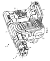
Fig. 1 illustrates a right perspective view of the anchor setting tool according to an embodiment of the invention; -
Fig. 2 illustrates a left perspective view of the anchor setting tool including a bit in the retention device according to an embodiment of the invention; -
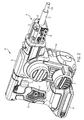
Fig. 3 illustrates a left side sectional view of the anchor setting tool according to an embodiment of the invention; -
Fig. 4 illustrates a partial left side sectional view of the anchor setting tool; -
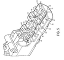
Fig. 5 illustrates a perspective view of the shroud of the bit retention device according to an embodiment of the invention; -
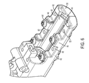
Fig. 6 illustrates a perspective view of the stationary plate of the bit retention device according to an embodiment of the invention. -
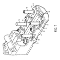
Fig. 7 illustrates a perspective view of the clamp plate and clamp members of the bit retention device according to an embodiment of the invention; -
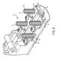
Fig. 8 illustrates a perspective view of the clamp plate spring assembly of the bit retention device according to an embodiment of the invention; -
Fig. 9 illustrates a perspective view of the bit retention device cage according to an embodiment of the invention; and -
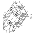
Fig. 10 illustrates a perspective view of the bit retention device. - Reference will now be made in detail to the presently preferred embodiments of the invention, examples of which are illustrated in the accompanying drawings.
Figs. 5-9 illustrate an inverted, or top-side down, view of the bit retention device components for a clear view thereof. - Referring now more particularly to the drawings,
Fig. 1 illustrates an anchor setting tool constructed in accordance with the teachings of the present invention. - With continuing reference to
FIG. 1 and additional reference toFIGS. 2-4 , thefastening tool 10 may include ahousing 12, amotor 14, a rotary-linearmotion transmission mechanism 414, abit retention device 16, atrigger 18, a control unit 22, and abattery 26, which provides electrical power to themotor assembly 14 and the control unit 22. Those skilled in the art will appreciate from this disclosure, however, that in place of, or in addition to thebattery 26, theanchor setting tool 10 may include an external power cord (not shown) for connection to an external power supply (not shown). While the anchor setting tool is illustrated as being electrically powered by a suitable power source or energy storage device, such as the battery pack, those skilled in the art will appreciate that the invention, in its broader aspects, may be constructed somewhat differently and that aspects of the present invention may have applicability to pneumatically powered or corded anchor setting tools. Furthermore, while aspects of the present invention are described herein and illustrated in the accompanying drawings in the context of an anchor setting tool, those of ordinary skill in the art will appreciate that the invention, in its broadest aspects, has further applicability, such as, for example, drilling tools and impacting tools. - The
housing 12 may include abody portion 12a, which may be configured to house themotor 14 andtransmission mechanism 414, and ahandle 12b. Thehousing body portion 12a is vertically arranged in thehousing 12 and has an upper portion and a lower portion. The lower portion of the housing includes themotor exhaust 17. Thehandle 12b may be configured to house the control unit 22. Thehandle 12b may provide thehousing 12 with a conventional pistol-grip appearance and may be unitarily formed with thebody portion 12a or may be a discrete fabrication that is coupled to thebody portion 12a, as by threaded fasteners (not shown). Thehandle 12b may be contoured so as to ergonomically fit a user's hand and/or may be equipped with a resilient and/or non-slip covering, such as an overmoldedthermoplastic elastomer 13. - The
trigger 18 may be coupled to thehousing 12 and is configured to receive an input from the user, typically by way of the user's finger, which may be employed in conjunction with a trigger switch 18a to generate a trigger signal that may be employed in whole or in part to initiate the cycling of thetool 10 to strike thestriking rod 400 and, in turn, thetool bit 20, and anchor (not shown). Thesetting pin portion 20a is inserted into the anchor such that when thetool bit 20 is struck by thestriking rod 400, the tool bit moves longitudinally within thebit retention device 16 to strike the body of the anchor and wedge the anchor into a workpiece, such as concrete. -
Fig. 1 also illustrates ahang hook 24 for hanging thetool 10 from a suspended surface. Further illustrated is a lock-off bar 28 that selectably prevents thetrigger 18 from being depressed. -
Fig. 3 illustrates an exemplary control system 22. The control system 22 controls the supply of power from the power source, such as thebattery 26, to themotor 14 as disclosed inU.S. Patent Application Serial No. 13/080,712 assigned to Black & Decker, Inc. of Newark, Delaware, which is hereby incorporated by reference in its entirety. - As shown in
Figs. 2-4 , thebit retention device 16 retains atool bit 20 having a settingpin portion 20a andstriking end 20b. As will be discussed,tool bits 20 are retained within thebit retention device 16 by a combination of plates and springs that move along rigid sleeves to accommodate bits having different thicknesses. - With reference to
Figs. 3 and4 , thetrigger 18 is arranged on thehousing 12 for controlling themotor 14. Aforward portion 12c of thehousing 12 can be in the form of a barrel 8 arranged substantially perpendicular to thebody portion 12a. Astriking rod 400 is mounted longitudinally within the barrel 8 for striking thetool bit 20, with a restoringspring 424 for returning the striking rod back to its original position after striking the tool bit. Thestriking rod 400 is moved in a reciprocating manner within the barrel 8. Thestriking rod 400 is shaped generally like a shaft, including afirst end 410 for striking thetool bit 20 and asecond end 412 to be impacted. During operation, thestriking rod 400 is driven to move and thefirst end 410 acts on astriking end 20b of thetool bit 20. Theforward portion 12c of thehousing 12 further includes thebit retention device 16 which is provided with a clampable opening for containing thetool bit 20. - As further shown in
Figs. 3 and4 , a multi-stagegear transmission mechanism 414, which can be a rotary-linear motor transmission mechanism, is arranged in thehousing body portion 12a for converting rotating motions of themotor 14 into impact motions of thestriking rod 400. Themotor 14 is mounted perpendicularly within thehousing body portion 12a, and has ahorizontal motor shaft 15 connected to the input end of the multi-stagegear transmission mechanism 414, including bevel gears. In this way, the rotation power of themotor 14 is transmitted to arotating shaft 416 which is mounted in the upper portion of thehousing body portion 12a by two bearings. In an exemplary embodiment, therotating shaft 416 is driven by agear 418 which is driven indirectly, for example, throughgear 419, by themotor shaft 15. The power output end of the multi-stagegear transmission mechanism 414 is mated with thestriking rod 400. - Optionally, a pair of inclined slots (not shown) is formed on the
rotating shaft 416. Animpact wheel 420 is mounted on therotating shaft 416. Optionally, theimpact wheel 420 comprises a pair of guiding slots (not shown) which are formed on its inner wall and opposite to the inclined slots (not shown) respectively. As a further option, a pair of steel balls (not shown) can be arranged movably in two chambers formed by the inclined slots and the guiding slots. When the inclined slots are moved relative to the guiding slots, the chambers formed thereby are moved with a result that the steel balls can be moved along with the chambers. Theimpact wheel 420 can thus be driven to rotate through the steel balls within the inclined slots when therotating shaft 416 is rotated. - A pair of
projections 422, which extend along the diameter direction of theimpact wheel 420, is provided on the periphery of the impact wheel. Anenergy storing spring 424 is mounted between theimpact wheel 420 and therotating shaft 416 in manner so that one end of theenergy storing spring 424 abuts to a shoulder of therotating shaft 416 and the other end of theenergy storing spring 424 abuts to a side surface of theimpact wheel 420. Under an axial biasing force of theenergy storing spring 424 acting upon theimpact wheel 420 along the axial direction of therotating shaft 416, theimpact wheel 420 is located at a first axial position relative to therotating shaft 416. In the first axial position, theimpact wheel 420 rotates in a circle on therotating shaft 416 and the steel balls. When theimpact wheel 420 is rotated to a position where theprojections 422 contact thesecond end 412 of thestriking rod 400, and thestriking rod 400 encounters a larger resistance that is difficult to overcome provisionally, theimpact wheel 420 is temporarily stopped from rotating by thestriking rod 400, so that theimpact wheel 420, with the cooperation of the steel wheels, guiding slots and inclined slots, overcomes the axial force of thespring 424, compresses theenergy storing spring 424 and moves from the first axial position to a second axial position relative to therotating shaft 416. At the second axial position, theprojection 422 of theimpact wheel 420 departs from thestriking rod 400, and the stopping is released. In this case, theenergy storing spring 424 starts to release its elastic potential energy. Under a function of rebound axial force of theenergy storing spring 424, theimpact wheel 420 is pressed back to its first axial position quickly, and is moved at a higher speed than that of therotating shaft 416 with the cooperation of the inclined slots, guiding slots and steel wheels. As a result, thesecond end 412 of thestriking rod 400 is impacted by theprojections 422 of theimpact wheel 420 to move at a high speed in a direction away from theprojections 422, and thestriking rod 400 strikes theend face 20b of thetool bit 20 quickly. In this way, a strike action is achieved. When theimpact wheel 420 is continuously driven to rotate and to be stopped by thestriking rod 400, the wheel enters into succeeding cycles, which will be achieved in the same manner. - Additional features of the motor and transmission mechanism are disclosed in
U.S. Patent No. 8,439,243 , which is hereby incorporated by reference in its entirety. - Referring now to
Figs. 5-10 , a bit retention device will be described. In an embodiment of the present invention, thebit retention device 16 includes an upper support member, a lower support member 2 coupled to the upper support member, astationary plate 60 suitably mounted to the upper support member, a spring-loadedclamp plate 70 slidably mounted to the upper support member, and a clampplate spring assembly 78. The upper support member and the lower support member, together, encase thestationary plate 60,clamp plate 70 and clampplate spring assembly 78. Thestationary plate 60 andclamp plate 70 releasably secure thetool bit 20 within thebit retention device 16. - As shown in
Figs. 1 ,2 and5 , the upper support member can be in the form of ashroud 30 disposed within theforward portion 12c of thehousing 12. Theforward portion 12c can extend perpendicularly to thebody portion 12a. Theshroud 30 can be secured within an opening in theforward portion 12c of thehousing 12 by means including, but not limited to, fasteners. Theshroud 30 can have an elongated body with afront portion 32 andrear portion 34 arranged in the longitudinal direction of theforward portion 12c, aninner surface 36, and anouter surface 38. Theshroud 30 can be insertably mounted within theforward portion 12c of thehousing 12 and secured to thehousing 12 at therear portion 34 by fasteners. Thefront portion 32 of theshroud 30 cantilevers from the opening in theforward portion 12c and forms the support for thestationary plate 60,clamp plate 70 and clampplate spring assembly 78 of thebit retention device 16. - The
front portion 32 of theshroud 30 includes notchedsurfaces 40 for retaining a front portion of the lower support surface. - As illustrated, for example, in
Fig. 5 , thefront portion 32 of theshroud 30 can be formed with opposinglateral side walls 42 and theinner surface 36 can be formed as avalley 44 therebetween. Thelateral side walls 42 can have a crenellated profile formed of alternatingupright sections 46 andnotches 48 extending in a direction perpendicular to the longitudinal direction of theshroud 30. As shown, thenotch sections 48 have a height that is shorter than the height of theupright sections 46. Theupright sections 46 andnotches 48 of one side of the shroud can be laterally opposite to the upright sections and notches of the opposite side wall. Theupright sections 46 andnotches 48 can be of equal longitudinal length. Alternatively, theupright sections 46 can have a different length from thenotch sections 48. For example, theupright sections 46 of theshroud 30 can be longer or shorter than thenotch sections 48. The crenellated profile provides a mounting surface for portions of the stationary plate, as discussed below. - Blind holes 50 can be provided in
upright sections 46. Theblind holes 50 allow for securing the stationary plate to theupright sections 46. Additionally, thenotch sections 48 have threadedapertures 52 for inserting components of the clamp plate spring assembly.Inner surfaces 36 of theshroud 30 can have ribbedsurfaces 54 integrally formed with theupright sections 46. The ribbed surfaces 54 support the stationary plate within theshroud 30. The left side of theshroud 30 inFig. 5 is the mirror image of the right side. - The
valley portion 44 of theshroud 30 has a V-shape as a main or central component of the cross-section. The V-shape of the shroud provides a controlled surface for the location of the various cylindrical anchor setting bits. - As shown in
Fig. 5 and more clearly inFig. 10 , theouter surface 38 of theshroud 30 includes a plurality of recesses orpockets 56 aligned with thenotch sections 46 of thelateral side walls 42. The recesses orpockets 56house securing members 58, such as internally threaded nuts, that secure the clamp plate spring assembly to theshroud 30. - The shroud can be formed from steel, sheet metal, or materials such as plastic, magnesium and aluminum.
- In an embodiment of the present invention, shown, for example, in
Fig. 6 , thestationary plate 60 is mounted to thevalley portion 44 on theinner surface 36 of theshroud 30. Thestationary plate 60 serves to align thetool bit 20 in the shroud. The stationary plate also provides a reinforced surface in theshroud 30 against which thetool bit 20 bears when the tool bit is inserted in the bit retention device. Thestationary plate 60 has an elongated body aligned with the longitudinal direction of theshroud 30. Thestationary plate 60 has a V-shape as a main or central component of the cross-section that corresponds to the contours of the V-shaped portion of the cross-section on theinner surface 36 of theshroud 30. - In addition to the V-shape portion of the cross-section, the
stationary plate 60 also includes a plurality oftabs 62 through which a threadedfastener 64 can secure the stationary plate, through theblind holes 50, to theupright sections 46 of theshroud 30. Thetabs 62 can be formed to project radially inward from an inner surface of thestationary plate 60 and to fold over theupright sections 46 of theshroud 30. Thetabs 62 can be arranged in laterally opposing pairs, that is, on opposite sides of thevalley 44 in theshroud 30. Thestationary plate 60 can be formed from any material including but not limited to, hardened steel. - In an embodiment of the present invention, shown, for example in
Fig. 7 , a spring-loadedclamp plate 70 is operatively connected to theshroud 30 for relative movement therewith. Theclamp plate 70 can be an elongated member that extends along the longitudinal direction of theshroud 30 andstationary plate 60. Theclamp plate 70 is mounted on an opposite side of thestationary plate 60 from theshroud 30. The spring-loadedclamp plate 70 floats between theshroud 30 and the lower support member on a plurality of rigidclamp plate sleeves 72. Theclamp plate 70 has a V-shape as a main component of the cross-section. The open portion of the V faces the open portion of the V-shape of thestationary plate 60. As a result, the V-shaped cross-section of the clamp plate aligned with the V-shaped cross-section of the stationary plate forms a diamond-shaped opening for inserting a bit into thebit retention device 16. The V-shaped portion of theclamp plate 70 provides a controlled surface for the location of the various sized, usually cylindrical, anchor setting bits. The clamping force between thestationary plate 60 and theclamp plate 70 provides the retention needed to keep the anchor setting tool bits attached to the power tool. Alternatively, the clamp plate element may be retained by a mechanical or electrically operated clamp. - Another structural characteristic of the
clamp plate 70 is that the front end of the clamp plate can be non-parallel. As shown for example inFigs. 7-9 , the clamp plate front end extends beyond the front end of the stationary plate in the direction of thesetting pin 20a. Such a configuration allows thetool bit 20 to leverage the more extended length as a support for easier installation. Alternatively, the front end of the stationary plate can extend beyond the front end of the clamp plate. - The
clamp plate 70 also includes a plurality oftabs 74 that are aligned with thenotch sections 48 of theshroud 30. Theclamp plate tabs 74 extend laterally from the center portion of the clamp plate. Theclamp plate 70 can have an aperture in eachtab 74 that is axially aligned with the threadedapertures 52. Thetabs 74 are arranged in a longitudinal direction of theshroud 30. At rest, thetabs 74 of the clamp plate are flush with horizontal surface portions of theupper support member 46. Stationary posts or clampplate sleeves 72 are inserted into the apertures in theclamp plate 70 and the shroud to locate the clamp plate relative to the shroud. The clamp plate can be constrained in the tool by one or more clamp plate sleeves that are aligned to theshroud 30 by means of fasteners. - Additionally, the
clamp plate sleeves 72 constrain movement of theclamp plate 70 to move only vertically with respect to the shroud. Thetabs 74 alternate with thetabs 62 of thestationary plate 60 along thelateral wall 42 of theshroud 30. - The
clamp plate 70 can also have a lead-in surface of alternate cross-section that guides the tool bit into the power tool. - In an embodiment, clamp
washers 76 can be secured to theclamp plate 70 around the clamp plate apertures. The clamp washers 76 may be placed between the clamp plate springs and the clamp plate. Theclamp washer 76 serves to distribute the load and create a rest surface for the springs, such as, for example, when the springs are compressed by entry of the tool bit into the bit retention device. - The
clamp plate 70 can be formed from any material including but not limited to hardened steel and sheet metal. - In an embodiment, shown in
Fig. 8 , for example, theclamp plate 70 can be slidably attached to theshroud 30 through one or more stationary posts or clampplate sleeves 72. Theclamp plate sleeves 72 are provided to constrain the motion of theclamp plate 70. Theclamp plate sleeves 72 can be elongated members that extend perpendicularly inward with respect to the longitudinal direction of theclamp plate 70. In an embodiment, a plurality ofclamp plate sleeves 72 allows theclamp plate 70 to move freely in a vertical direction with respect to theshroud 30 andstationary plate 60. Specifically, theclamp plate sleeves 72 allow theclamp plate 70 to slidably move toward and away from theshroud 30 andstationary plate 60. Theclamp plate sleeves 72 are inserted into the clamp plate apertures and corresponding threadedapertures 52 of theshroud 30. The ends of theclamp plate sleeves 72 extend through theshroud 30 into the shroud recess orpocket 56 where the ends of the sleeves encircle bolts that are threadedly secured into theshroud 30, as shown inFig. 10 . As such, the clamp plate sleeves are fixed in place and act as spacers between thestationary plate 60 andclamp plate 70, wherein the clamp plate moves axially on the clamp plate springs 80. Theclamp plate sleeve 72 and clampwashers 76 can be formed from any material, including but not limited to steel. - In an embodiment of the present invention, as shown in
Fig. 7 , theclamp plate sleeve 72 can be hollow such that a fastening member can pass through the sleeve and into theshroud 30. Fastening members include, but are not limited to screws. In an embodiment, theclamp plate sleeves 72 can be tubular as shown inFig. 7 , for example. Alternatively theclamp plate sleeves 72 can have a cross-section that is rectangular, triangular, oval or any other suitable shape that corresponds to the aperture in the clamp plate. - The
clamp plate sleeves 72 prevents theclamp plate 70 from shifting sideways with respect to theshroud 30 when the clamp plate moves vertically along the clamp plate sleeve and when the clamp plate andstationary plate 60 are holding atool bit 20. - In an embodiment shown in
Fig. 8 , the clampplate spring assembly 78 includes one or more biasing members or clamp plate springs 80 that apply a force to theclamp plate 70 such that the clamp plate is resiliently connected to theshroud 30. The reactionary elements or coils of theclamp plate spring 80 are in contact with theclamp plate 70. The clamp plate springs 80 provide a clamping force between the clamp plate and the stationary plate. The clamping force provides the retention needed to keep the anchor setting tool bits attached to the power tool. - The clamp plate springs 80 can be mounted between the
clamp plate 70 and the lower support member. In an embodiment of the present invention, theclamp plate spring 80, such as, for example, helical compression springs, are disposed around theclamp plate sleeves 72 to provide a clamping force against theclamp plate 70 to hold thetool bit 20. The clamp plate springs 80 provide resistance against movement of theclamp plate 70 toward the lower support member by biasing the clamp plate in the direction of thestationary plate 60. - The clamp plate springs 80 may be of various types including, but not limited to coil springs, torsion springs, and leaf springs. Although helical coil springs are illustrated, the clamp plate element may alternatively be retained by a mechanical or electrically operated clamp.
- When a
tool bit 20 is inserted along the longitudinal axis of theshroud 30 between thestationary plate 60 and theclamp plate 70, the diameter of the tool bit radially displaces theclamp plate 70 away from thestationary plate 60. In addition, the resistance provided by the clamp plate springs 80 ensures an interference fit of thetool bit 20 between thestationary plate 60 and theclamp plate 70. - In an embodiment of the present invention as shown in
Fig. 9 , the lower support member orcage 82 is attached to theshroud 30 to create an enclosure around the stationary plate, clamp plate and clamp plate spring assembly. Thecage 82 is stationary and serves as the reaction surface for the clamp plate springs 80. Thecage 82 has a substantially planar body withside guard 84 andfront guard 86 portions that project toward theshroud 30. Theguard portions front guard portions 86 are on a front face of thecage 82. The front face of thecage 82 includes acentral opening 88 for receiving thetool bit 20 into thebit retention device 16. - The
cage 82 has apertures therethrough for inserting fastening elements to secure the cage to theshroud 30. - As shown in the cross-sectional view of
Fig. 3 and inFig. 9 , a rear portion of thecage 90 and a rear portion of theshroud 92 are disposed within theforward portion 12c of thehousing 12. Therear portion 90 of thecage 82 is connected to therear portion 92 of the shroud by threadedscrews 94a or the like, while the front end portion of thecage 82 rests in the notchedfront surfaces 40 of the shroud. The forward portion of the cage can be bolted to the shroud through theclamp sleeves 72 with steel screws, threadedscrews 94a orbolts 94b. The ends of the bolts or steel screws project through the threaded apertures in the upper surface of theshroud 30 into the shroud recesses 56 where they can be secured in place by a fastening element, such as a nut. Thecage 82 can be formed from any material including but not limited to hardened steel, standard steel, and aluminum. - Replaceable inserts or anchor setting bits having various diameters and lengths are retained during use of the tool. Changing between different sized tool bits is made easier and faster than in existing bit retention devices. Although a cylindrical tool bit is illustrated, the bits can be of any shape including but not limited to rectangular, triangular and oval. The spring-loaded clamp plate and clamp plate spring assembly automatically adjusts and applies a retaining force to accommodate different sizes of bits. As a result, no tools are needed to load or unload the tool bits.
- While aspects of the present invention are described herein and illustrated in the accompanying drawings in the context of a fastening tool, those of ordinary skill in the art will appreciate that the invention, in its broadest aspects, has further applicability.
- It will be appreciated that the above description is merely exemplary in nature and is not intended to limit the present disclosure, its application or uses. While specific examples have been described in the specification and illustrated in the drawings, it will be understood by those of ordinary skill in the art that various changes may be made and equivalents may be substituted for elements thereof without departing from the scope of the present disclosure as defined in the claims. Furthermore, the mixing and matching of features, elements and/or functions between various examples is expressly contemplated herein, even if not specifically shown or described, so that one of ordinary skill in the art would appreciate from this disclosure that features, elements and/or functions of one example may be incorporated into another example as appropriate, unless described otherwise, above. Moreover, many modifications may be made to adapt a particular situation or material to the teachings of the present disclosure without departing from the essential scope thereof. Therefore, it is intended that the present disclosure not be limited to the particular examples illustrated by the drawings and described in the specification as the best mode presently contemplated for carrying out the teachings of the present disclosure, but that the scope of the present disclosure will include any embodiments falling within the foregoing description and the appended claims.
Claims (15)
- A bit retention device comprising:an upper support member having an inner surface and an outer surface;a lower support member fixed to the upper support member;a stationary plate mounted to the inner surface of the upper support member; anda clamp plate opposing the stationary plate and slidably moveable between the upper support member and the lower support member.
- The bit retention device according to claim 1, further comprising a plurality of clamp plate sleeves fixed between the upper support member and the lower support member and surrounded by corresponding clamp plate springs, the clamp plate springs resiliently biasing the clamp plate toward the stationary plate.
- The bit retention device according to claim 2, wherein the clamp plate sleeves are rigid.
- The bit retention device according to claim 1, wherein the clamp plate is spring-biased toward the stationary plate.
- The bit retention device according to claim 1, wherein the upper support member has an elongated body extending in a longitudinal direction and crenellated side walls.
- The bit retention device according to claim 5, wherein the stationary plate comprises tabs projecting radially inward and folded over upright sections of the crenellated side walls of the upper support member.
- The bit retention device according to claim 6, wherein the clamp plate comprises tabs that, in the longitudinal direction of the upper support member, alternate with the tabs of the stationary plate.
- The bit retention device according to claim 1, wherein the stationary plate has a substantially V-shaped cross-section.
- The bit retention device according to claim 8, wherein the clamp plate has a substantially V-shaped cross-section that opposes the substantially V-shaped cross-section of the stationary plate.
- The bit retention device according to claim 1, wherein the stationary plate and clamp plate have front ends and,
wherein the front end of the stationary plate is non-parallel to the front end of the clamp plate. - The bit retention device according to claim 10, wherein the front end of the clamp plate front end extends beyond the front end of the stationary plate.
- The bit retention device according to claim 1, wherein the lower support member comprises guard portions that project from a lower surface thereof toward the upper support member.
- An anchor setting tool comprising:a housing having a handle portion, a transmission portion and a forward portion;a bit retention device disposed at least partially within the forward portion for retaining a tool bit in a longitudinal direction, the bit retention device including:a stationary plate; anda clamp plate biased toward the stationary plate,a motor;a transmission mechanism arranged in the transmission portion and driven by the motor;a striking rod disposed in the forward portion between the transmission mechanism and the bit retention device, the striking rod being moveable in a reciprocating manner from an impact received from the transmission mechanism to strike the tool bit; anda power source to power the motor.
- The anchor setting tool according to claim 13, further comprising an upper support member and a lower support member, encasing the stationary plate and the clamp plate.
- A method for retaining a bit in a bit retention device having a longitudinally extending upper support member and a longitudinally extending lower support member encasing a clamp plate spring assembly, comprising:providing a stationary plate mounted to the lower support member;providing a spring-biased clamp plate opposing the stationary plate and slidably moveable between the upper support member and the lower support member, and biased toward the stationary plate; andinserting a tool bit between the stationary plate and the clamp plate to move the clamp plate away from the stationary plate.
Applications Claiming Priority (2)
| Application Number | Priority Date | Filing Date | Title |
|---|---|---|---|
| US201461944843P | 2014-02-26 | 2014-02-26 | |
| US14/628,698 US10022851B2 (en) | 2014-02-26 | 2015-02-23 | Cordless anchor setting tool bit retention device |
Publications (2)
| Publication Number | Publication Date |
|---|---|
| EP2913157A1 true EP2913157A1 (en) | 2015-09-02 |
| EP2913157B1 EP2913157B1 (en) | 2016-12-21 |
Family
ID=52595114
Family Applications (1)
| Application Number | Title | Priority Date | Filing Date |
|---|---|---|---|
| EP15156649.4A Active EP2913157B1 (en) | 2014-02-26 | 2015-02-26 | Anchor setting tool bit retention device |
Country Status (2)
| Country | Link |
|---|---|
| US (2) | US10022851B2 (en) |
| EP (1) | EP2913157B1 (en) |
Families Citing this family (1)
| Publication number | Priority date | Publication date | Assignee | Title |
|---|---|---|---|---|
| US11945084B2 (en) * | 2021-04-26 | 2024-04-02 | Snap-On Incorporated | Offset impact mechanism for a hammer tool |
Citations (6)
| Publication number | Priority date | Publication date | Assignee | Title |
|---|---|---|---|---|
| US1425482A (en) * | 1919-11-10 | 1922-08-08 | Thomas Thompson | Retaining device for a riveting set |
| US1647201A (en) * | 1926-03-03 | 1927-11-01 | Ingersoll Rand Co | Broaching attachment |
| US2055898A (en) * | 1930-12-15 | 1936-09-29 | Sullivan Machinery Co | Impact tool |
| US2357045A (en) * | 1941-10-15 | 1944-08-29 | Cunningham Co M E | Toolholder |
| US4007795A (en) * | 1976-02-13 | 1977-02-15 | Skil Corporation | Attachment for a rotary-hammer tool |
| US20100089969A1 (en) * | 2008-10-15 | 2010-04-15 | Cheryon Limited | Nailer device |
Family Cites Families (15)
| Publication number | Priority date | Publication date | Assignee | Title |
|---|---|---|---|---|
| US1605941A (en) | 1925-04-11 | 1926-11-09 | Ingersoll Rand Co | Steel retainer |
| US1776922A (en) | 1927-09-27 | 1930-09-30 | Gardner Denver Co | Tool retainer |
| US1770680A (en) | 1927-12-21 | 1930-07-15 | Ingersoll Rand Co | Steel retainer |
| US1755269A (en) | 1928-04-19 | 1930-04-22 | Gardner Denver Co | Tool holder |
| US1832471A (en) | 1930-03-21 | 1931-11-17 | Chicago Pneumatic Tool Co | Chuck for drilling machines |
| US2265427A (en) | 1940-11-02 | 1941-12-09 | Ingersoll Rand Co | Implement retainer |
| US2406514A (en) | 1944-06-05 | 1946-08-27 | Jack & Heintz Prec Ind Inc | Roll v block support |
| US2489923A (en) | 1948-01-08 | 1949-11-29 | Worthington Pump & Mach Corp | Tool retainer for percussive tools |
| US3579912A (en) * | 1969-04-25 | 1971-05-25 | Engis Equipment Co | Universal clamp for abrasive tool |
| US3865198A (en) | 1972-12-08 | 1975-02-11 | Vernon L Price | Adapter assembly having wedge head with saddle fit latch for impact tool units |
| US4162065A (en) | 1978-06-20 | 1979-07-24 | Andrew Rea | Work holding fixture for cylindrical workpieces |
| US4231580A (en) | 1978-08-07 | 1980-11-04 | Henri Emonet | Lost motion tool retainer |
| DE3721771A1 (en) | 1987-07-01 | 1989-01-12 | Hilti Ag | HAND DEVICE |
| US5354075A (en) * | 1993-11-02 | 1994-10-11 | Smith & Nephew Richards Inc. | Keyless drill chuck |
| US7147546B1 (en) * | 2005-10-06 | 2006-12-12 | Professional Tool Manufacturing, Llc | Tool holder with moveable alignment finger |
-
2015
- 2015-02-23 US US14/628,698 patent/US10022851B2/en active Active
- 2015-02-26 EP EP15156649.4A patent/EP2913157B1/en active Active
-
2018
- 2018-06-19 US US16/012,246 patent/US10875169B2/en active Active
Patent Citations (7)
| Publication number | Priority date | Publication date | Assignee | Title |
|---|---|---|---|---|
| US1425482A (en) * | 1919-11-10 | 1922-08-08 | Thomas Thompson | Retaining device for a riveting set |
| US1647201A (en) * | 1926-03-03 | 1927-11-01 | Ingersoll Rand Co | Broaching attachment |
| US2055898A (en) * | 1930-12-15 | 1936-09-29 | Sullivan Machinery Co | Impact tool |
| US2357045A (en) * | 1941-10-15 | 1944-08-29 | Cunningham Co M E | Toolholder |
| US4007795A (en) * | 1976-02-13 | 1977-02-15 | Skil Corporation | Attachment for a rotary-hammer tool |
| US20100089969A1 (en) * | 2008-10-15 | 2010-04-15 | Cheryon Limited | Nailer device |
| US8439243B2 (en) | 2008-10-15 | 2013-05-14 | Chervon Limited | Nailer device |
Also Published As
| Publication number | Publication date |
|---|---|
| US10022851B2 (en) | 2018-07-17 |
| EP2913157B1 (en) | 2016-12-21 |
| US20180297185A1 (en) | 2018-10-18 |
| US10875169B2 (en) | 2020-12-29 |
| US20150239114A1 (en) | 2015-08-27 |
Similar Documents
| Publication | Publication Date | Title |
|---|---|---|
| AU2010101466A4 (en) | Nailer Device | |
| EP2694253B1 (en) | Rotary impact device | |
| US8424734B2 (en) | Clamping mechanism for an auto hammer | |
| JP2002254358A (en) | Electric tool | |
| US20170197305A1 (en) | Chisel Head Attachment For Electric Drills and Screw Drivers and the Like and Electric Chisels | |
| AU2011100046A4 (en) | Electric Hammer | |
| US10875169B2 (en) | Cordless anchor setting tool | |
| US20230032843A1 (en) | Attachment for powered hammer | |
| AU2010101287A4 (en) | Auto Hammer | |
| AU2010101284A4 (en) | Auto Hammer | |
| AU2010101281A4 (en) | Auto Hammer | |
| WO2014086870A1 (en) | An apparatus for arranging and feeding fasteners | |
| KR102198389B1 (en) | Electric driver | |
| JP2008062345A (en) | Power tool | |
| AU2010101288A4 (en) | Auto Hammer | |
| AU2010101285A4 (en) | Auto Hammer | |
| CN212683856U (en) | Nail holding device | |
| JP2009167654A (en) | Scraper, scraper attachment, and scraper device | |
| JP2004090216A (en) | Portable tool | |
| CA2721619A1 (en) | Auto hammer | |
| JP2004106171A (en) | Portable tool |
Legal Events
| Date | Code | Title | Description |
|---|---|---|---|
| PUAI | Public reference made under article 153(3) epc to a published international application that has entered the european phase |
Free format text: ORIGINAL CODE: 0009012 |
|
| AK | Designated contracting states |
Kind code of ref document: A1 Designated state(s): AL AT BE BG CH CY CZ DE DK EE ES FI FR GB GR HR HU IE IS IT LI LT LU LV MC MK MT NL NO PL PT RO RS SE SI SK SM TR |
|
| AX | Request for extension of the european patent |
Extension state: BA ME |
|
| 17P | Request for examination filed |
Effective date: 20160301 |
|
| RBV | Designated contracting states (corrected) |
Designated state(s): AL AT BE BG CH CY CZ DE DK EE ES FI FR GB GR HR HU IE IS IT LI LT LU LV MC MK MT NL NO PL PT RO RS SE SI SK SM TR |
|
| GRAP | Despatch of communication of intention to grant a patent |
Free format text: ORIGINAL CODE: EPIDOSNIGR1 |
|
| INTG | Intention to grant announced |
Effective date: 20160929 |
|
| GRAS | Grant fee paid |
Free format text: ORIGINAL CODE: EPIDOSNIGR3 |
|
| GRAA | (expected) grant |
Free format text: ORIGINAL CODE: 0009210 |
|
| AK | Designated contracting states |
Kind code of ref document: B1 Designated state(s): AL AT BE BG CH CY CZ DE DK EE ES FI FR GB GR HR HU IE IS IT LI LT LU LV MC MK MT NL NO PL PT RO RS SE SI SK SM TR |
|
| REG | Reference to a national code |
Ref country code: GB Ref legal event code: FG4D |
|
| REG | Reference to a national code |
Ref country code: CH Ref legal event code: EP |
|
| REG | Reference to a national code |
Ref country code: IE Ref legal event code: FG4D |
|
| REG | Reference to a national code |
Ref country code: AT Ref legal event code: REF Ref document number: 855061 Country of ref document: AT Kind code of ref document: T Effective date: 20170115 |
|
| REG | Reference to a national code |
Ref country code: DE Ref legal event code: R096 Ref document number: 602015001022 Country of ref document: DE |
|
| PG25 | Lapsed in a contracting state [announced via postgrant information from national office to epo] |
Ref country code: LV Free format text: LAPSE BECAUSE OF FAILURE TO SUBMIT A TRANSLATION OF THE DESCRIPTION OR TO PAY THE FEE WITHIN THE PRESCRIBED TIME-LIMIT Effective date: 20161221 |
|
| REG | Reference to a national code |
Ref country code: LT Ref legal event code: MG4D |
|
| REG | Reference to a national code |
Ref country code: NL Ref legal event code: MP Effective date: 20161221 |
|
| PG25 | Lapsed in a contracting state [announced via postgrant information from national office to epo] |
Ref country code: NO Free format text: LAPSE BECAUSE OF FAILURE TO SUBMIT A TRANSLATION OF THE DESCRIPTION OR TO PAY THE FEE WITHIN THE PRESCRIBED TIME-LIMIT Effective date: 20170321 Ref country code: GR Free format text: LAPSE BECAUSE OF FAILURE TO SUBMIT A TRANSLATION OF THE DESCRIPTION OR TO PAY THE FEE WITHIN THE PRESCRIBED TIME-LIMIT Effective date: 20170322 Ref country code: SE Free format text: LAPSE BECAUSE OF FAILURE TO SUBMIT A TRANSLATION OF THE DESCRIPTION OR TO PAY THE FEE WITHIN THE PRESCRIBED TIME-LIMIT Effective date: 20161221 Ref country code: LT Free format text: LAPSE BECAUSE OF FAILURE TO SUBMIT A TRANSLATION OF THE DESCRIPTION OR TO PAY THE FEE WITHIN THE PRESCRIBED TIME-LIMIT Effective date: 20161221 |
|
| REG | Reference to a national code |
Ref country code: AT Ref legal event code: MK05 Ref document number: 855061 Country of ref document: AT Kind code of ref document: T Effective date: 20161221 |
|
| PG25 | Lapsed in a contracting state [announced via postgrant information from national office to epo] |
Ref country code: BE Free format text: LAPSE BECAUSE OF NON-PAYMENT OF DUE FEES Effective date: 20170228 Ref country code: HR Free format text: LAPSE BECAUSE OF FAILURE TO SUBMIT A TRANSLATION OF THE DESCRIPTION OR TO PAY THE FEE WITHIN THE PRESCRIBED TIME-LIMIT Effective date: 20161221 Ref country code: RS Free format text: LAPSE BECAUSE OF FAILURE TO SUBMIT A TRANSLATION OF THE DESCRIPTION OR TO PAY THE FEE WITHIN THE PRESCRIBED TIME-LIMIT Effective date: 20161221 Ref country code: FI Free format text: LAPSE BECAUSE OF FAILURE TO SUBMIT A TRANSLATION OF THE DESCRIPTION OR TO PAY THE FEE WITHIN THE PRESCRIBED TIME-LIMIT Effective date: 20161221 |
|
| PG25 | Lapsed in a contracting state [announced via postgrant information from national office to epo] |
Ref country code: NL Free format text: LAPSE BECAUSE OF FAILURE TO SUBMIT A TRANSLATION OF THE DESCRIPTION OR TO PAY THE FEE WITHIN THE PRESCRIBED TIME-LIMIT Effective date: 20161221 |
|
| PG25 | Lapsed in a contracting state [announced via postgrant information from national office to epo] |
Ref country code: EE Free format text: LAPSE BECAUSE OF FAILURE TO SUBMIT A TRANSLATION OF THE DESCRIPTION OR TO PAY THE FEE WITHIN THE PRESCRIBED TIME-LIMIT Effective date: 20161221 Ref country code: CZ Free format text: LAPSE BECAUSE OF FAILURE TO SUBMIT A TRANSLATION OF THE DESCRIPTION OR TO PAY THE FEE WITHIN THE PRESCRIBED TIME-LIMIT Effective date: 20161221 Ref country code: IS Free format text: LAPSE BECAUSE OF FAILURE TO SUBMIT A TRANSLATION OF THE DESCRIPTION OR TO PAY THE FEE WITHIN THE PRESCRIBED TIME-LIMIT Effective date: 20170421 Ref country code: RO Free format text: LAPSE BECAUSE OF FAILURE TO SUBMIT A TRANSLATION OF THE DESCRIPTION OR TO PAY THE FEE WITHIN THE PRESCRIBED TIME-LIMIT Effective date: 20161221 Ref country code: SK Free format text: LAPSE BECAUSE OF FAILURE TO SUBMIT A TRANSLATION OF THE DESCRIPTION OR TO PAY THE FEE WITHIN THE PRESCRIBED TIME-LIMIT Effective date: 20161221 |
|
| PG25 | Lapsed in a contracting state [announced via postgrant information from national office to epo] |
Ref country code: ES Free format text: LAPSE BECAUSE OF FAILURE TO SUBMIT A TRANSLATION OF THE DESCRIPTION OR TO PAY THE FEE WITHIN THE PRESCRIBED TIME-LIMIT Effective date: 20161221 Ref country code: BE Free format text: LAPSE BECAUSE OF FAILURE TO SUBMIT A TRANSLATION OF THE DESCRIPTION OR TO PAY THE FEE WITHIN THE PRESCRIBED TIME-LIMIT Effective date: 20161221 Ref country code: SM Free format text: LAPSE BECAUSE OF FAILURE TO SUBMIT A TRANSLATION OF THE DESCRIPTION OR TO PAY THE FEE WITHIN THE PRESCRIBED TIME-LIMIT Effective date: 20161221 Ref country code: PT Free format text: LAPSE BECAUSE OF FAILURE TO SUBMIT A TRANSLATION OF THE DESCRIPTION OR TO PAY THE FEE WITHIN THE PRESCRIBED TIME-LIMIT Effective date: 20170421 Ref country code: PL Free format text: LAPSE BECAUSE OF FAILURE TO SUBMIT A TRANSLATION OF THE DESCRIPTION OR TO PAY THE FEE WITHIN THE PRESCRIBED TIME-LIMIT Effective date: 20161221 Ref country code: BG Free format text: LAPSE BECAUSE OF FAILURE TO SUBMIT A TRANSLATION OF THE DESCRIPTION OR TO PAY THE FEE WITHIN THE PRESCRIBED TIME-LIMIT Effective date: 20170321 Ref country code: AT Free format text: LAPSE BECAUSE OF FAILURE TO SUBMIT A TRANSLATION OF THE DESCRIPTION OR TO PAY THE FEE WITHIN THE PRESCRIBED TIME-LIMIT Effective date: 20161221 Ref country code: IT Free format text: LAPSE BECAUSE OF FAILURE TO SUBMIT A TRANSLATION OF THE DESCRIPTION OR TO PAY THE FEE WITHIN THE PRESCRIBED TIME-LIMIT Effective date: 20161221 |
|
| REG | Reference to a national code |
Ref country code: DE Ref legal event code: R097 Ref document number: 602015001022 Country of ref document: DE |
|
| PG25 | Lapsed in a contracting state [announced via postgrant information from national office to epo] |
Ref country code: MC Free format text: LAPSE BECAUSE OF FAILURE TO SUBMIT A TRANSLATION OF THE DESCRIPTION OR TO PAY THE FEE WITHIN THE PRESCRIBED TIME-LIMIT Effective date: 20161221 |
|
| PLBE | No opposition filed within time limit |
Free format text: ORIGINAL CODE: 0009261 |
|
| STAA | Information on the status of an ep patent application or granted ep patent |
Free format text: STATUS: NO OPPOSITION FILED WITHIN TIME LIMIT |
|
| 26N | No opposition filed |
Effective date: 20170922 |
|
| REG | Reference to a national code |
Ref country code: IE Ref legal event code: MM4A |
|
| PG25 | Lapsed in a contracting state [announced via postgrant information from national office to epo] |
Ref country code: DK Free format text: LAPSE BECAUSE OF FAILURE TO SUBMIT A TRANSLATION OF THE DESCRIPTION OR TO PAY THE FEE WITHIN THE PRESCRIBED TIME-LIMIT Effective date: 20161221 |
|
| REG | Reference to a national code |
Ref country code: FR Ref legal event code: ST Effective date: 20171031 |
|
| PG25 | Lapsed in a contracting state [announced via postgrant information from national office to epo] |
Ref country code: LU Free format text: LAPSE BECAUSE OF NON-PAYMENT OF DUE FEES Effective date: 20170226 |
|
| PG25 | Lapsed in a contracting state [announced via postgrant information from national office to epo] |
Ref country code: FR Free format text: LAPSE BECAUSE OF NON-PAYMENT OF DUE FEES Effective date: 20170228 |
|
| PG25 | Lapsed in a contracting state [announced via postgrant information from national office to epo] |
Ref country code: SI Free format text: LAPSE BECAUSE OF FAILURE TO SUBMIT A TRANSLATION OF THE DESCRIPTION OR TO PAY THE FEE WITHIN THE PRESCRIBED TIME-LIMIT Effective date: 20161221 Ref country code: IE Free format text: LAPSE BECAUSE OF NON-PAYMENT OF DUE FEES Effective date: 20170226 |
|
| REG | Reference to a national code |
Ref country code: CH Ref legal event code: PL |
|
| PG25 | Lapsed in a contracting state [announced via postgrant information from national office to epo] |
Ref country code: MT Free format text: LAPSE BECAUSE OF NON-PAYMENT OF DUE FEES Effective date: 20170226 |
|
| PG25 | Lapsed in a contracting state [announced via postgrant information from national office to epo] |
Ref country code: CH Free format text: LAPSE BECAUSE OF NON-PAYMENT OF DUE FEES Effective date: 20180228 Ref country code: LI Free format text: LAPSE BECAUSE OF NON-PAYMENT OF DUE FEES Effective date: 20180228 |
|
| PG25 | Lapsed in a contracting state [announced via postgrant information from national office to epo] |
Ref country code: HU Free format text: LAPSE BECAUSE OF FAILURE TO SUBMIT A TRANSLATION OF THE DESCRIPTION OR TO PAY THE FEE WITHIN THE PRESCRIBED TIME-LIMIT; INVALID AB INITIO Effective date: 20150226 |
|
| PG25 | Lapsed in a contracting state [announced via postgrant information from national office to epo] |
Ref country code: CY Free format text: LAPSE BECAUSE OF FAILURE TO SUBMIT A TRANSLATION OF THE DESCRIPTION OR TO PAY THE FEE WITHIN THE PRESCRIBED TIME-LIMIT Effective date: 20161221 |
|
| PG25 | Lapsed in a contracting state [announced via postgrant information from national office to epo] |
Ref country code: MK Free format text: LAPSE BECAUSE OF FAILURE TO SUBMIT A TRANSLATION OF THE DESCRIPTION OR TO PAY THE FEE WITHIN THE PRESCRIBED TIME-LIMIT Effective date: 20161221 |
|
| PG25 | Lapsed in a contracting state [announced via postgrant information from national office to epo] |
Ref country code: TR Free format text: LAPSE BECAUSE OF FAILURE TO SUBMIT A TRANSLATION OF THE DESCRIPTION OR TO PAY THE FEE WITHIN THE PRESCRIBED TIME-LIMIT Effective date: 20161221 |
|
| PG25 | Lapsed in a contracting state [announced via postgrant information from national office to epo] |
Ref country code: AL Free format text: LAPSE BECAUSE OF FAILURE TO SUBMIT A TRANSLATION OF THE DESCRIPTION OR TO PAY THE FEE WITHIN THE PRESCRIBED TIME-LIMIT Effective date: 20161221 |
|
| PGFP | Annual fee paid to national office [announced via postgrant information from national office to epo] |
Ref country code: GB Payment date: 20230105 Year of fee payment: 9 Ref country code: DE Payment date: 20221230 Year of fee payment: 9 |