EP2910685B1 - Fish lift and method for cleaning a fish lift - Google Patents
Fish lift and method for cleaning a fish lift Download PDFInfo
- Publication number
- EP2910685B1 EP2910685B1 EP15154775.9A EP15154775A EP2910685B1 EP 2910685 B1 EP2910685 B1 EP 2910685B1 EP 15154775 A EP15154775 A EP 15154775A EP 2910685 B1 EP2910685 B1 EP 2910685B1
- Authority
- EP
- European Patent Office
- Prior art keywords
- container
- water
- hoistway
- opening
- fish lift
- Prior art date
- Legal status (The legal status is an assumption and is not a legal conclusion. Google has not performed a legal analysis and makes no representation as to the accuracy of the status listed.)
- Active
Links
- 241000251468 Actinopterygii Species 0.000 title claims description 92
- 238000000034 method Methods 0.000 title claims description 11
- 238000004140 cleaning Methods 0.000 title description 6
- XLYOFNOQVPJJNP-UHFFFAOYSA-N water Substances O XLYOFNOQVPJJNP-UHFFFAOYSA-N 0.000 claims description 176
- 230000000903 blocking effect Effects 0.000 claims description 18
- 238000011144 upstream manufacturing Methods 0.000 claims description 8
- 238000005086 pumping Methods 0.000 description 32
- 238000011010 flushing procedure Methods 0.000 description 8
- 230000002262 irrigation Effects 0.000 description 3
- 238000003973 irrigation Methods 0.000 description 3
- 238000012423 maintenance Methods 0.000 description 3
- 238000010926 purge Methods 0.000 description 3
- 230000001419 dependent effect Effects 0.000 description 2
- 238000013461 design Methods 0.000 description 2
- 239000000758 substrate Substances 0.000 description 2
- 230000009182 swimming Effects 0.000 description 2
- 230000009471 action Effects 0.000 description 1
- 238000013459 approach Methods 0.000 description 1
- 230000008901 benefit Effects 0.000 description 1
- 230000033228 biological regulation Effects 0.000 description 1
- 230000001276 controlling effect Effects 0.000 description 1
- 230000001186 cumulative effect Effects 0.000 description 1
- 238000011161 development Methods 0.000 description 1
- 230000018109 developmental process Effects 0.000 description 1
- 238000007599 discharging Methods 0.000 description 1
- 230000001771 impaired effect Effects 0.000 description 1
- 230000004941 influx Effects 0.000 description 1
- 230000014759 maintenance of location Effects 0.000 description 1
- 230000007257 malfunction Effects 0.000 description 1
- 210000003903 pelvic floor Anatomy 0.000 description 1
- 230000008569 process Effects 0.000 description 1
- 230000001105 regulatory effect Effects 0.000 description 1
- 230000000630 rising effect Effects 0.000 description 1
- 230000002000 scavenging effect Effects 0.000 description 1
Images


Classifications
-
- E—FIXED CONSTRUCTIONS
- E02—HYDRAULIC ENGINEERING; FOUNDATIONS; SOIL SHIFTING
- E02B—HYDRAULIC ENGINEERING
- E02B8/00—Details of barrages or weirs ; Energy dissipating devices carried by lock or dry-dock gates
- E02B8/08—Fish passes or other means providing for migration of fish; Passages for rafts or boats
- E02B8/085—Devices allowing fish migration, e.g. fish traps
-
- Y—GENERAL TAGGING OF NEW TECHNOLOGICAL DEVELOPMENTS; GENERAL TAGGING OF CROSS-SECTIONAL TECHNOLOGIES SPANNING OVER SEVERAL SECTIONS OF THE IPC; TECHNICAL SUBJECTS COVERED BY FORMER USPC CROSS-REFERENCE ART COLLECTIONS [XRACs] AND DIGESTS
- Y02—TECHNOLOGIES OR APPLICATIONS FOR MITIGATION OR ADAPTATION AGAINST CLIMATE CHANGE
- Y02A—TECHNOLOGIES FOR ADAPTATION TO CLIMATE CHANGE
- Y02A40/00—Adaptation technologies in agriculture, forestry, livestock or agroalimentary production
- Y02A40/60—Ecological corridors or buffer zones
Definitions
- the invention relates to a fish lift and a method for cleaning or for operating a fish lift according to the preamble of claim 1 and of claim 13 and 14.
- a fish lift is known for transporting fish between an overflow of a barrage and an underwater barrage, the fish lift comprising a well and a container, the well comprising a lower orifice below a level of the subsea with a lower entrance to the well is movable between an upper position and a lower position, wherein the container is designed as a floating container, the floating container on its way between the upper position and the lower position in a trapped in the well below the container volume of water, the container by water drainage the volume of water trapped in the shaft is lowered or the container is raised by water flow to the volume of water trapped in the shaft.
- a fish lift for transporting fish between an overflow of a barrage and an underwater of the barrage
- the fish lift comprising a well and a reservoir, the well comprising a lower well below a level of the lower well with a lower sluice entrance, the reservoir between an upper position and a lower position is movable
- the container is designed as a floating container, wherein the floating container on its way between the upper position and the lower position in a shaft below the container enclosed water volume is floated, wherein the container is lowered by water drainage from the trapped water volume in the shaft or wherein the container is raised by water flow to the trapped in the shaft water volume.
- the fish lift according to the invention comprises a pumping device, which is designed as a water drainage device.
- a pumping device which works as a water drainage device.
- By pumping which works as a water drainage device, it is possible by pumping the trapped under the container in the shaft volume of water to drive the container even at elevated water level of the underwater in its lower position and to hold in this position.
- This allows the fish lift to stay in operation during an elevated water level of the underwater and allow the fish to continue their way from the headwater to the underwater and vice versa.
- the conditions to be met per year with respect to the operating days can be met without difficulty.
- operation of the pumping means as a water supply means provides the ability to increase the pressure in the volume of water trapped under the container such that upon operation of the pumping means when the container is in the up position, a between the container and the shaft lying annular gap can be cleaned by flowing due to the increased pressure on the container water.
- cleaning can be carried out automatically by a corresponding programming of a control device of the fish lift and is therefore extremely cost-effective, in contrast to a manually performed cleaning.
- the pumping device interpreted in terms of their performance such that from this from the trapped water volume in the shaft, a volume flow is discharged, which is greater than a volume flow, which from the upper water the trapped volume of water flows in.
- a complete lowering of the container at elevated water level of the underwater is also ensured if penetrates through leaks upper water in the shaft.
- the pumping device in terms of its performance such that a volumetric flow which is greater than a volumetric flow which flows out of the trapped water volume into the underwater is supplied to it by the water volume trapped in the shaft.
- a flushing of the annular gap between the container and the shaft in the upper position of the container is also possible if water flows from the enclosed volume of water through leaks in the underwater.
- the floating container has a buoyancy, which is dimensioned such that a transport space of the container is filled to more than 50% and in particular over 70% with water.
- a buoyancy which is dimensioned such that a transport space of the container is filled to more than 50% and in particular over 70% with water.
- the pumping device with a mechanical pump, a first line for connecting the pump to the shaft and a second line for connecting the pump to the environment, wherein the first line opens into a bottom region of the shaft into the shaft and the second line outside of Einschwimmzonen or Ausschwimmzonen into the environment and in particular into the underwater or in the upper water opens.
- This ensures that the pumping device does not affect the flow conditions in the floating zones or Ausschwimmzonen.
- the pump for forming the water drainage device is preferably designed as a suction pump and / or the pump for forming the water supply device as Pressure pump formed.
- a pump is sufficient to perform the functions of Niederfahrens despite increased water level of the underwater and the purging of the annular gap.
- the upper retaining means ensures that the container is not pushed upwards out of the shaft during rinsing.
- a blocking means of the stop means between a locking position and a release position is movable and wherein the stop means blocks the container in its lower position when the locking means is in its blocking position.
- the container can be kept in its lower position at elevated water level of the underwater without the pumping device must be operated for this purpose.
- a determination of the container in its lower position also in the lower position allows a rinsing process, which can be carried out both as a pressure purge or as a suction or as an alternating pressure and suction.
- the blocking means of the stop means by one or more slides and / or pawls to form.
- it is provided evenly distributed over a circumference of the container to provide three slides and / or pawls to avoid an inclination of the container floating against the blocking means.
- an actuation of the blocking means of the stop means it is provided to make these electrically or hydraulically, wherein the release position is preferably caused by a spring force and the locking position against this spring force is electromagnetically or hydraulically induced, so that the container is released in a malfunction of the locking means ,
- the container is preferably provided to form the container with two lateral openings and one upper opening, wherein the first lateral opening is aligned with the upper opening of the shaft, and wherein the second lateral opening is aligned with the lower opening of the shaft.
- the container in the shaft preferably guided by a guide means against rotation.
- the guide means are in particular formed by a rail or by two rails or by three rails.
- the second embodiment By implementing the second embodiment, it is possible to realize in the upper water in different water depths entrances in the fish lift or exits from the fish lift, so that the fish according to the preferred depth of water swim into the container of the fish lift or swim out of the container can.
- the embodiments bring both the individual and cumulative execution with the advantage that the attractiveness of the fish lift is increased because the fish in the preferred depth of water and can swim out.
- the container in particular above its opposite lateral openings with at least one further opening, wherein this is aligned in particular to one of the further openings of the shaft so that it lies opposite the further opening in the upper position of the container and the upper water is accessible via this, and / or which is in particular aligned on one of the further openings of the shaft, that it faces the further opening in the lower position of the container and the underwater is accessible via this.
- a height (H20) of the leading into the underwater opening of the container is 1.5 times and in particular at least twice a height (H19) of the leading into the upper water opening of the container and that Height (H10) of the opening of the shaft leading into the underwater 1.5 times, and in particular at least twice, a height (H8) of the opening leading into the upper water of the shaft.
- the invention provides a method for operating or cleaning operation of a fish lift, wherein the fish lift is formed according to at least one of the device claims, wherein the method first a lock exit and a lock entrance of the fish lift are closed, then the float tank by supplying water in the Shaft is raised to an upper position against an upward movement stopping retaining means and finally by a pumping device further water is forced into the interior of the shaft below the container, so that water through an arranged between the container and the shaft annular gap on the floating container over in such a way pushed up out of the shaft, that dirt is flushed out.
- This makes it possible with minimal effort to permanently ensure a smooth running of the working as a piston in the shaft container.
- the invention also provides a method for operating a fish lift in case of flooding, wherein the fish lift is designed in particular according to at least one of the preceding device claims, wherein for lowering the floating tank from its upper position a lock entrance of the fish lift is closed and opened a drain and flushing channel
- the floating container is then lowered into the lower shaft via the drainage and irrigation channels as well as through the removal of water, which is pumped out of the interior of the shaft by a pumping device, under the floating container Position is lowered, in which case the pumping device after the float tank has reached the lower position remains active at least to the extent that the floating tank is held in its lower position until again a lifting of the container is provided or until the underwater has dropped below a high water level.
- the fish lift can also be operated at high tide, so that its availability increases and the fish lift can still transport fish even in extreme natural conditions.
- fish in the context of the invention also encompasses other living beings in whose nature it is to travel upstream or downstream.
- a valve means a shut-off device which is suitable for regulating a water flow.
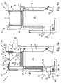
- FIGS. 1a to 1e show a fish lift 1 standing at average level N5 underwater 5 in different positions, the fish lift 1 and a barrage 4, in which the fish lift 1 is integrated, in schematic, sectioned side views is shown. Based on FIGS. 1a and 1e the fish lift 1 is first described in its basic function.
- the fish lift 1 is provided for transporting fish 2 between a headwater 3 of the barrage 4 and the underwater 5 of the barrage 4.
- the fish lift 1 comprises a shaft 6 and a container 7.
- the shaft 6 comprises an upper opening 8 below a level N3 of the upper water 3 with an upper lock exit 9.
- the shaft 6 comprises a lower one below the level N5 of the lower water 5 Opening 10 with a lower lock entrance 11.
- the container 7 is between a in the FIG. 1a shown upper position S3 and one in the Figure 1e shown lower position S5 movable.
- the container 7 is guided on two opposing rails 12, 13.
- the container 7, which in the FIG. 1a is shown in its upper position S3, is shaped such that this surrounds the two rails 12, 13.
- the container 7 comprises a transport space 14.
- the transport space 14 forms a basin 15.
- the basin 15 has a basin floor 16, on which the sole substrate 17 is arranged.
- the basin 15 represents a largely natural environment for the fish 2 and other living beings.
- the container 7 has a first lateral opening 19 and a second lateral opening 20 which lead into the transport space 14.
- the second lateral opening 20 is in the position S5 below the level N5 of the underwater 5 and leads to the underwater 5 and a Einschwimmzone 21.
- the second side opening 20 of the container 7 is in the lower position S5 the lock entrance 11 and the lower opening 10 of the shaft 6 in such a way that when the lock entrance 11 is open a relation to the container 7 surrounding the interior 22 of the shaft 6 shielded connection to the underwater 5 consists.
- the lock entrance 11 is formed in the second rail 13, this second rail 13 has a directed onto the opening 20 of the container 7 lower rail opening.
- the locking member 24 is formed as a slider 26 and the actuating means, not shown, includes actuators and a linkage.
- the slider 26 is in a raised position, so that the path between the underwater 5 and the transport space 14 of the container 7 is released for the fish 2.
- the locking member 24 and the actuating means of the lock input 11, not shown, are arranged in a cavity of the second rail 13, not shown, and thus are protected in the shaft 6.
- In the transport space 14 of the container 7 and in the Einschwimmzone 21 of the underwater 5 is in in the Lower position S5 standing container 7 and open lock entrance 11 a Leitströmung L5 via a first Leitigan pumps 32 manufactured.
- the first conductive water supply 32 comprises a supply channel 33, a supply channel valve 34 and a Leitigandüse 35.
- the supply channel 33 is fed from the upper water 3, wherein the inflowing through the supply channel 33 amount of water is controlled by the supply channel valve 34.
- the Leitigandüse 35 is the first lateral opening 19 of the container 7 opposite, when this is in its lower position S5. Through the Leitigandüse 35 flows from the upper water 3 water as Leitströmung L5 in the transport space 14 of the container 7 and through the second opening 20 and the opened lock entrance 11 further into the underwater 5 and the Einschwimmzone 21st
- the fish lift 1 furthermore comprises a discharge device 301.
- This comprises a discharge lock 38, by means of which a discharge opening 39 formed in the shaft 6 can be closed.
- the discharge opening 39 is arranged below the lower opening 10 and leads into a discharge and irrigation channel 40, which leads under a bottom 41 of the Einschwimmzone 21, past the Einschwimmzone 21 in the underwater 5.
- a valve 34 ' is then opened and upper water from the supply channel 33 via a diversion 35' under the container 7 passed.
- a flushing device 302 is formed, through which upper water can flow away under the container 7 past the Leitigandüse 35, without the guide flow L5 formed in the container 7 and in the Einschwimmzone 21 is thereby impaired.
- the fish lift 1 further comprises a second lead water supply 49.
- This comprises a supply channel 50, which is fed from the upper water 3, and a supply channel valve 51.
- the supply channel 50 of the second lead water supply 49 flows in front of the lower lock entrance 11 in the Einschwimmzone 21 of the underwater 5.
- the supply channel valve 51 is closed, so that no upper water 3 is passed through the second Leitiganmakers 49 into the underwater 5.
- the second lead water supply 49 is activated when the lock inlet 11 is closed in order to maintain the lock flow in the underwater 5.
- the lock exit 9 is closed when the container 7 is in the lower position S5 or moves to the lower position (see Figure 1c ).
- the lock exit 9 comprises a locking member 52 and actuating means, not shown, wherein its opening 8 is formed by a pipe section, which the upper water 3 through a on the upper opening 8 of the shaft 6 and the opening 19 of the standing in the upper position S3 container. 7 aligned upper rail opening with the interior 22 of the shaft 6 connects.
- the locking member 52 is formed as a slider 55 and the actuating means, not shown, are formed by actuators, not shown, and a non-illustrated linkage. Through the closed lock exit 9, the inflow of upper water 3 into the interior 22 of the shaft 6 is prevented.
- the container 7 is designed as a floating container 59 and comprises a float 60.
- the upper position S3 has the container 7 - as in the FIG. 1a shown when the floating container 7 with its upper side 61 against a shaft 6 upwardly bounding retaining means 62, which is designed as a stop 63, floats and is prevented by this on a further, upward lifting movement.
- the upper lock exit 9 can be opened so that the upper water 3 flows into the transport space 14 of the container 7.
- a ceiling 64 of the container 7, which forms the top 61, has a third opening 65 through which the transport space 14 of the container 7 is accessible from above.
- the container 7 Since the container 7 is held by the stop 63 with its upper side 61 below the level N3 of the upper water 3, the upper water 3, which flows through the upper lock exit 9 into the transport space 14, swells upwards out of the container 7 through the opening 65.
- the overflowing upper water 3 flows over an upper edge 66 of the shaft 6 and the third Leitiganmakers 49 'is supplied.
- This turns into the transport space 14 after opening the lock exit 9 from a Ausschwimmzone 21 'of the upper water 3 outgoing upper Leitströmung 67 through which the fish 2 are directed out of the transport space 14 out into the upper water 3 or from the upper water 3 in the transport space fourteenth be directed.
- the lock flow L5 is maintained in the underwater 5 through the second and / or the third Leitiganmakers 49 and 49 '.
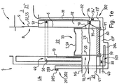
- This auxiliary device 201 is designed as a pump device 202, which operates as a water drainage device or as a water drainage device and as a water supply device, and comprises a mechanical pump 203, a first line 204 for connecting the pump 203 to the shaft 6 and a second line 205 for connecting the pump 203 with the environment U4 the barrage 4 includes.
- the first line 204 opens in a bottom portion 69 'of the shaft 6 in the shaft 6 and this opens the second line 205 outside the Einschwimmzone 21 and Ausschwimmzone 21' in the environment U4 and in particular in the underwater 5 or in the upper water.
- the container 7 drops when discharging contained in the interior 22 of the shaft 6 water down to lower stop means 91, so that the lateral opening 20 on the lower opening 10 of the Shaft 6 is aligned.
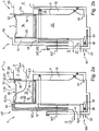
- FIGS. 2a to 2e show in analogy to the FIGS. 1a to 1f the lowering of the container 7 at below average level N5 'standing underwater 5. Regarding the FIGS. 2a and 2b will be on the description to the FIGS. 1a and 1b directed.
- FIGS. 2c and 2d now show the container 7 on its way from the upper position S3 to the lower position S5.
- a lowering of the container 7 still takes place by means of the discharge device 301, since a shaft water level N6 is still above the level N5 'of the underwater 5.
- This turns gradually in a transport space 14 of the container 7 of the Shaft water level N6, since the interior 22 of the shaft 6 and the transport space 14 of the container 7 communicate with each other via the openings 19, 20 of the container 7 and an existing between the container 7 and the shaft 6 annular gap.
- effluent water is symbolized by an arrow P301.
- the additional device 201 is taken as a pumping device 202 in operation and pumped under the container 7 from the trapped volume of water V6 water.
- the pumping device 202 conveys the water into the environment U4.
- the lowering of the container 7 takes place at the closed lower lock entrance 11.
- the container 7 has then arrived in its lower position S5 and rests on the stop means 91.
- the pumping device 202 now works only to the extent in which water flows under the container 7 in order to keep it in its lower position.
- the flushing device 302 is normally closed in order to avoid an additional load on the pumping device 202.
- a float of the container 7 by blocking means 92 to prevent, which only in the FIGS. 2e and 2f are shown and which fix the container 7 in its lower position S5.
- the blocking means 92 comprise at least one slide 93, which can be extended by water pressure against a spring, not shown, in the interior 22 of the shaft 6, wherein a supply line and a valve for controlling the water supply are not shown. If the fish lift 1 has blocking means 92, operation of the pumping device 202 while the container 7 is in the position S5 is not necessary.
- the lower sluice input 11 is closed again and the pump device 202, which may be in operation, is switched off.
- the influx of upper water 3 is activated via the first guide water supply 32 and / or the purging device 302 is opened, wherein the discharge device 301 is closed.
- the container 7 floats up to the extent in which water is supplied via the first Leitiganmakers 32 and / or the flushing device 302 under the container and in the extent upwards, in the water from the interior 22 of the shaft 6 between Shaft 6 and container 7 flows under the container 7 and a determined by the buoyancy of the container 7 equilibrium is reached. If fish 2 are in the shaft 6 above a ceiling 64 of the container 7, they are guided during the floating of the container 7 through its opening 65 in the transport space 14, so that they are not exposed to danger.
- the additional device 201 as pumping device 202 in the manner of a water drainage device and a water supply device is operated such that it presses water from the environment U4 in the interior 22 of the container 7, it is possible in the position S5 (see FIG. 2b ), in which the container 7 rests against the stop 63 and the slider 55 is closed, to flush the annular gap R between the container 7 and shaft 6, since the pumped by the pumping device 202 under the container 7 water only to the container 7 over can exit at the top.
- An inflow of water through the side openings 19 and 20 of the container 7 in the transport space 14 of the container 7 is thereby at least largely prevented that the two openings 19, 20 are sealed by the rails 12 and 13 respectively.
- the pumping device 202 can replace a crane and, in particular, shortens the time required for servicing the container, since the positioning of a crane and the fixing and loosening of a carrying harness are eliminated as working steps.
- FIG. 3 In the FIG. 3 are shown in a schematic plan view of the shaft 6 and the container 7 of the fish lift 1 shown in the preceding figures.
- the annular gap R can be seen, which is formed between the shaft 6 and the container 7.
- the container 7 is - as stated above - guided on rails 12, 13, which are formed by the shaft 6.
- the opening 65 of the container 7 passes via a slope 94 in the top 61 of the container 7, which forms a ceiling 64. With the ceiling 64, the container 7 in its upper position does not strike against this shown retaining means.
- the opening 65 opens to a transport space 14 of the container 7. This is dependent on the position of the container 7 in the shaft 6 through the upper opening 8 or the lower opening 10 accessible.
- FIG. 4 is a schematic representation of a second embodiment of a fish lift 1a shown in side view.
- a fish lift comprises a shaft 6 in the FIG. 4 shown second embodiment between a lower opening 10 and an upper opening 8 two more in an underwater 5 leading openings 10a and 10b. Both the lower opening 10 and the overlying openings 10a and 10b are closed by locking members 24 and 24a and 24b.
- locking members 24 and 24a and 24b are closed by locking members 24 and 24a and 24b.
- the container 7 which is designed as a floating container, by means of a pumping device 202, which includes a mechanical pump 203, moved in the shaft 6 in the illustrated elevator position AS2 and prevented in this by a clamping means 92a from floating , Further elevator positions AS1, AS3 and AS4 of the container 7 are in the FIG. 4 indicated by dashed lines.
- each opening 10, 10a and 10b is associated with a further Leitigandüse 95, 95a and 95b.
- Leitigandüsen 95 and 95 b active because the locking members 24 and 24b are closed.
- a water level W6, which lies at a level N5 of the underwater 5, is established, since underwater 5 via a transport space 14 of the container 7 and its upper opening 65 into an interior space 22 of the shaft 6 flows.
- the water above the container 7 flows depending on a lifting speed with which the container 7 is raised to the container 7 from under the container 7 and / or is pushed by the container 7 up to flow through a third Leitiganmakers 49 'in the underwater 5, the fish 2 are collected through the upper opening 65 in the transport space 14 of the container 7 when the container 7 is moved to the elevator position AS4.
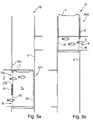
- FIGS. 5a and 5b is now shown in abstract representation, a third embodiment of a fish lift 1b in a lower elevator position AS1 and an upper elevator position AS4, being dispensed with a representation of Leitigandüsen, Leitpumpe, a pumping device and stop and clamping means.
- a container 7, which is movable in a shaft 6, comprises, in contrast to the containers shown in the preceding figures, not only two opposite lateral openings 19, 20, which leads to a first lateral opening 8 of the shaft 6, which leads into an upper water 3 , and aligned with a second lateral opening 10 of the duct 6, which leads into an underwater 5, but also comprises a third lateral opening 20a, which is arranged above the lateral opening 20 in the container 7.
- This further lateral opening 20a is aligned in the elevator position AS1 on a further opening 10a of the shaft 6, so that fish 2 in the elevator position AS1 with open locking members 24 and 24a from the underwater 5 in a transport space 14 of the container 7 through the openings 10, 20 and 10a, 20a can swim in and out.
- FIG. 5b is shown as the container 7 in the elevator position AS4 at open blocking member 52 is and the fish 2 on the openings 19, 8 in the upper water 3 off and can swim.
- the openings 20 and 20a of the container 7 are closed by the shaft 6.
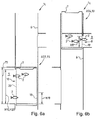
- FIG. 6a and 6b is now shown in abstract representation, a fourth embodiment of a fish lift 1c in a lower elevator position AS1 and an upper elevator position AS4, with a representation of Leitigandüsen, Leitigan supplies, a pumping device and stop and clamping means has been omitted.
- a container 7, which is movable in a shaft 6, comprises an opening 20, which is adapted to an opening 10 of the shaft 6 leading into the underwater 5, and an opening 19, which opens onto an opening 8 of the shaft 6 leading into the upper water 3 is adjusted.
- the directed to the underwater 5 openings 20 and 10 heights H20 and H10 which are made three times as high as the upper water 3 directed openings 19 and 8 with heights H19 and H8.
- FIG. 6b the container 7 is shown in the elevator position AS4, in which its opening 10 is closed by the shaft 6 and in which the fish 2 through the openings 19, 8 with open blocking member 52 in the upper water 3 and can swim out.
Landscapes
- Engineering & Computer Science (AREA)
- General Engineering & Computer Science (AREA)
- Life Sciences & Earth Sciences (AREA)
- Marine Sciences & Fisheries (AREA)
- Mechanical Engineering (AREA)
- Civil Engineering (AREA)
- Structural Engineering (AREA)
- Farming Of Fish And Shellfish (AREA)
Description
Die Erfindung betrifft einen Fischlift und ein Verfahren zum Reinigen bzw. zum Betrieb eines Fischlifts gemäß dem Oberbegriff des Anspruchs 1 bzw. des Anspruchs 13 bzw. 14. Aus der
Demnach offenbart die
Weiterhin ist auch aus der
Es ist Aufgabe der Erfindung, einen Fischlift vorzuschlagen, bei welchem ein störungsfreies Heben und Senken des Behälters auch bei einem extremen Wasserstand des Unterwassers gewährleistet ist. Weiterhin ist es Aufgabe der Erfindung ein Verfahren zum Betrieb eines Fischlifts in einer derartigen Extremsituation sowie ein Verfahren zum Reinigen eines Fischlifts vorzuschlagen.It is an object of the invention to provide a fish lift, in which a trouble-free lifting and lowering of the container is ensured even at an extreme water level of the underwater. It is another object of the invention to propose a method for operating a fish lift in such an extreme situation and a method for cleaning a fish lift.
Diese Aufgabe wird ausgehend von den Merkmalen des Oberbegriffs des Anspruchs 1 bzw. 13 bzw. 14 durch die kennzeichnenden Merkmale des Anspruchs 1 bzw. des Verfahrensanspruch 13 bzw. 14 gelöst. In den Unteransprüchen sind vorteilhafte und zweckmäßige Weiterbildungen angegeben.This object is achieved on the basis of the features of the preamble of
Der erfindungsgemäße Fischlift umfasst eine Pumpeinrichtung, die als Wasserabflusseinrichtung ausgebildet ist. Durch eine Pumpeinrichtung, die als Wasserabflusseinrichtung arbeitet, ist es möglich, durch ein Abpumpen des unter dem Behälter in dem Schacht eingeschlossenen Wasservolumens, den Behälter auch bei erhöhtem Wasserstand des Unterwassers in seine untere Stellung zu fahren und in dieser Stellung zu halten. Hierdurch kann der Fischlift während eines erhöhten Wasserstandes des Unterwassers in Betrieb bleiben und den Fischen weiterhin den Weg vom Oberwasser ins Unterwasser und umgekehrt ermöglich. Somit können die hinsichtlich der Betriebstage pro Jahr zu erfüllenden Auflagen ohne Schwierigkeiten eingehalten werden. Weiterhin bietet ein Betrieb der Pumpeinrichtung als Wasserzuflusseinrichtung die Möglichkeit, den Druck in dem unter dem Behälter eingeschlossenen Wasservolumen zu erhöhen, so dass bei einem Betrieb der Pumpeinrichtung bei in der oberen Stellung stehendem Behälter ein zwischen dem Behälter und dem Schacht liegender Ringspalt durch auf Grund des erhöhten Drucks an dem Behälter vorbeiströmendes Wasser gereinigt werden kann. Eine derartige Reinigung kann automatisch durch eine entsprechende Programmierung einer Kontrolleinrichtung des Fischlifts durchgeführt werden und ist deshalb im Gegensatz zu einer händisch durchgeführten Reinigung äußerst kostengünstig.The fish lift according to the invention comprises a pumping device, which is designed as a water drainage device. By pumping, which works as a water drainage device, it is possible by pumping the trapped under the container in the shaft volume of water to drive the container even at elevated water level of the underwater in its lower position and to hold in this position. This allows the fish lift to stay in operation during an elevated water level of the underwater and allow the fish to continue their way from the headwater to the underwater and vice versa. Thus, the conditions to be met per year with respect to the operating days can be met without difficulty. Further, operation of the pumping means as a water supply means provides the ability to increase the pressure in the volume of water trapped under the container such that upon operation of the pumping means when the container is in the up position, a between the container and the shaft lying annular gap can be cleaned by flowing due to the increased pressure on the container water. Such cleaning can be carried out automatically by a corresponding programming of a control device of the fish lift and is therefore extremely cost-effective, in contrast to a manually performed cleaning.
Weiterhin ist in einer bevorzugten Ausführungsform vorgesehen, die Pumpeinrichtung in ihrer Leistungsfähigkeit derart auszulegen, dass von dieser aus dem im Schacht eingeschlossenen Wasservolumen ein Volumenstrom abgeführt wird, welcher größer ist als ein Volumenstrom, welcher aus dem Oberwasser dem eingeschlossenen Wasservolumen zuströmt. Hierdurch ist ein vollständiges Absenken des Behälters bei erhöhtem Wasserstand des Unterwassers auch dann sicher gestellt, wenn durch Leckstellen Oberwasser in den Schacht eindringt.Furthermore, it is provided in a preferred embodiment, the pumping device interpreted in terms of their performance such that from this from the trapped water volume in the shaft, a volume flow is discharged, which is greater than a volume flow, which from the upper water the trapped volume of water flows in. As a result, a complete lowering of the container at elevated water level of the underwater is also ensured if penetrates through leaks upper water in the shaft.
Bevorzugt ist es auch vorgesehen, die Pumpeinrichtung in ihrer Leistungsfähigkeit derart auszulegen, dass von dieser dem im Schacht eingeschlossenen Wasservolumen ein Volumenstrom zugeführt wird, welcher größer ist als ein Volumenstrom, welcher aus dem eingeschlossenen Wasservolumen in das Unterwasser abströmt. Hierdurch ist ein Freispülen des Ringspalts zwischen dem Behälter und dem Schacht in der oberen Stellung des Behälters auch dann möglich, wenn aus dem eingeschlossenen Wasservolumen durch Leckstellen Wasser in das Unterwasser abfließt.Preferably, it is also provided to design the pumping device in terms of its performance such that a volumetric flow which is greater than a volumetric flow which flows out of the trapped water volume into the underwater is supplied to it by the water volume trapped in the shaft. In this way, a flushing of the annular gap between the container and the shaft in the upper position of the container is also possible if water flows from the enclosed volume of water through leaks in the underwater.
Bevorzugt weist der Schwimmbehälter einen Auftrieb auf, welcher derart bemessen ist, dass ein Transportraum des Behälters zu über 50% und insbesondere zu über 70% mit Wasser gefüllt ist. Durch einen derartigen, ähnlich wie ein Eisberg schwimmenden Schwimmbehälter ist sicher gestellt, dass die sich in dem Innenraum des Schwimmbehälter aufhaltenden Fische ausreichend Wasser zur Verfügung haben.Preferably, the floating container has a buoyancy, which is dimensioned such that a transport space of the container is filled to more than 50% and in particular over 70% with water. By such, similar to an iceberg floating floating container is ensured that the residing in the interior of the floating vessel fish have sufficient water available.
Erfindungsgemäß ist es vorgesehen, die Pumpeinrichtung mit einer mechanischen Pumpe, einer ersten Leitung zur Verbindung der Pumpe mit dem Schacht und einer zweiten Leitung zur Verbindung der Pumpe mit der Umgebung auszustatten, wobei die erste Leitung in einem Bodenbereich des Schachts in den Schacht mündet und wobei die zweite Leitung außerhalb von Einschwimmzonen bzw. Ausschwimmzonen in die Umgebung und insbesondere in das Unterwasser oder in das Oberwasser mündet. Hierdurch wird sichergestellt, dass die Pumpeinrichtung die Strömungsverhältnisse in den Einschwimmzonen bzw. Ausschwimmzonen nicht beeinflusst.According to the invention, it is provided to equip the pumping device with a mechanical pump, a first line for connecting the pump to the shaft and a second line for connecting the pump to the environment, wherein the first line opens into a bottom region of the shaft into the shaft and the second line outside of Einschwimmzonen or Ausschwimmzonen into the environment and in particular into the underwater or in the upper water opens. This ensures that the pumping device does not affect the flow conditions in the floating zones or Ausschwimmzonen.
Weiterhin ist die Pumpe zur Bildung der Wasserabflusseinrichtung bevorzugt als Saugpumpe ausgebildet und/oder ist die Pumpe zur Bildung der Wasserzuflusseinrichtung als Druckpumpe ausgebildet. Hierdurch ist bei einer Ausbildung als Saug- und Druckpumpe eine Pumpe ausreichend, um die Funktionen des Niederfahrens trotz erhöhtem Wasserstand des Unterwassers und des Freispülens des Ringspalts auszuführen.Furthermore, the pump for forming the water drainage device is preferably designed as a suction pump and / or the pump for forming the water supply device as Pressure pump formed. As a result, in a design as a suction and pressure pump, a pump is sufficient to perform the functions of Niederfahrens despite increased water level of the underwater and the purging of the annular gap.
Weiterhin ist es bevorzugt vorgesehen, den Schacht mit einer unter einem Niveau des Oberwassers liegenden oberen Öffnung mit einem oberen Schleusenausgang auszustatten. Hierdurch können Fische in der oberen Stellung des Behälters ohne weitere Maßnahmen einfach ein- und ausschwimmen.Furthermore, it is preferably provided to equip the shaft with an upper opening below a level of the upper water with an upper lock outlet. As a result, fish in the upper position of the container without further action simply swim on and off.
Es ist bevorzugt auch vorgesehen, den Fischlift mit einem oberen Rückhaltemittel auszustatten, wobei der Behälter in der oberen Stellung derart an dem oberen Rückhaltemittel anliegt, dass dieser an einer weiteren Bewegung nach oben gehindert ist, so dass - wie oben beschrieben - zwischen dem Behälter und einer Innenwand des Schachts ein Ringspalt ausgebildet ist, durch welchen Wasser aus dem eingeschlossenen Wasservolumen an dem Behälter vorbei nach oben austritt, wenn die Pumpeinrichtung unter dem Behälter Wasser in einen Innenraum des Schachts drückt. Durch das obere Rückhaltemittel ist sicher gestellt, dass der Behälter beim Freispülen nicht nach oben aus dem Schacht herausgedrückt wird.It is also preferably provided to equip the fish lift with an upper retaining means, wherein the container in the upper position so abuts the upper retaining means that it is prevented from further upward movement, so that - as described above - between the container and an annular wall is formed in an inner wall of the duct, through which water emerges from the enclosed volume of water past the container upwards, when the pumping device presses water under the container into an interior space of the duct. The upper retaining means ensures that the container is not pushed upwards out of the shaft during rinsing.
Weiterhin ist es bevorzugt vorgesehen, den Fischlift mit einem Anschlagmittel auszustatten, wobei ein Sperrmittel des Anschlagmittels zwischen einer Sperrstellung und einer Freigabestellung verfahrbar ist und wobei das Anschlagmittel den Behälter in seiner unteren Stellung blockiert, wenn das Sperrmittel in seiner Sperrstellung steht. Hierdurch kann der Behälter bei erhöhtem Wasserstand des Unterwassers in seiner unteren Stellung gehalten werden, ohne dass hierzu die Pumpeinrichtung betrieben werden muss. Weiterhin ermöglicht eine derartige Festlegung des Behälters in seiner unteren Stellung auch in der unteren Stellung einen Spülvorgang, welcher sowohl als Druckspülung oder als Saugspülung oder als alternierende Druck- und Saugspülung durchgeführt werden kann.Furthermore, it is preferably provided to equip the fish lift with a stop means, wherein a blocking means of the stop means between a locking position and a release position is movable and wherein the stop means blocks the container in its lower position when the locking means is in its blocking position. In this way, the container can be kept in its lower position at elevated water level of the underwater without the pumping device must be operated for this purpose. Furthermore, such a determination of the container in its lower position also in the lower position allows a rinsing process, which can be carried out both as a pressure purge or as a suction or as an alternating pressure and suction.
Es ist bevorzugt auch vorgesehen, das Sperrmittel des Anschlagmittels durch einen oder mehrere Schieber und/oder Sperrklinken zu bilden. Insbesondere ist es vorgesehen, gleichmäßig auf einen Umfang des Behälters verteilt drei Schieber und/oder Sperrklinken vorzusehen, um eine Schrägstellung des gegen das Sperrmittel anschwimmenden Behälters zu vermeiden. Hinsichtlich einer Betätigung des Sperrmittels des Anschlagmittels ist es vorgesehen, diese elektrisch oder hydraulisch vorzunehmen, wobei die Freigabestellung vorzugsweise durch eine Federkraft herbeigeführt wird und die Sperrstellung gegen diese Federkraft elektromagnetisch oder hydraulisch herbeigeführt wird, so dass der Behälter bei einer Funktionsstörung von dem Sperrmittel freigegeben wird.It is also preferably provided, the blocking means of the stop means by one or more slides and / or pawls to form. In particular, it is provided evenly distributed over a circumference of the container to provide three slides and / or pawls to avoid an inclination of the container floating against the blocking means. With regard to an actuation of the blocking means of the stop means, it is provided to make these electrically or hydraulically, wherein the release position is preferably caused by a spring force and the locking position against this spring force is electromagnetically or hydraulically induced, so that the container is released in a malfunction of the locking means ,
Weiterhin ist es bevorzugt vorgesehen, den Behälter mit zwei seitlichen Öffnungen und einer oberen Öffnung auszubilden, wobei die erste seitliche Öffnung auf die obere Öffnung des Schachts ausgerichtete ist und wobei die zweite seitliche Öffnung auf die untere Öffnung des Schachts ausgerichtet ist. Hierdurch ist ausschließlich eine vertikale Verfahrbewegung erforderlich, um sowohl in der unteren Stellung als auch in der oberen Stellung einen Zugang zum Unterwasser bzw. Oberwasser herzustellen.
Um mit dem Behälter die unter Öffnung des Schachts und die obere Öffnung des Schachts präzise anfahren zu können, ist der Behälter in dem Schacht bevorzugt durch Führungsmittel verdrehsicher geführt. Hierbei sind die Führungsmittel insbesondere durch eine Schiene oder durch zwei Schienen oder durch drei Schienen gebildet.Furthermore, it is preferably provided to form the container with two lateral openings and one upper opening, wherein the first lateral opening is aligned with the upper opening of the shaft, and wherein the second lateral opening is aligned with the lower opening of the shaft. As a result, only a vertical movement is required to produce access to the underwater or upper water both in the lower position and in the upper position.
In order to be able to approach the container precisely under the opening of the shaft and the upper opening of the shaft, the container in the shaft preferably guided by a guide means against rotation. In this case, the guide means are in particular formed by a rail or by two rails or by three rails.
Weiterhin ist es bevorzugt vorgesehen, den Schacht zwischen der in das Unterwasser führenden unteren Öffnung und der in das Oberwasser führenden oberen Öffnung mit wenigstens einer weiteren verschließbare Öffnung auszustatten, welche in das Unterwasser führt, und/oder oberhalb der in das Oberwasser führenden oberen Öffnung mit wenigsten einer weiteren verschließbare Öffnung auszustatten, welche in das Oberwasser führt. Durch die Realisierung der ersten Ausführungsvariante ist es möglich, im Unterwasser in verschiedenen Wassertiefen Einstiege in den Fischlift bzw. Ausstiege aus dem Fischlift zu realisieren, so dass die Fische entsprechend der von ihnen bevorzugten Wassertiefe in den Behälter des Fischlifts einschwimmen bzw. aus dem Behälter ausschwimmen können. Durch die Realisierung der zweiten Ausführungsvariante ist es möglich, im Oberwasser in verschiedenen Wassertiefen Einstiege in den Fischlift bzw. Ausstiege aus dem Fischlift zu realisieren, so dass die Fische entsprechend der von ihnen bevorzugten Wassertiefe in den Behälter des Fischlifts einschwimmen bzw. aus dem Behälter ausschwimmen können. Die Ausführungsvarianten bringen sowohl in Einzelausführung als auch in kumulativer Ausführung den Vorteil mit sich, dass die Attraktivität des Fischlifts erhöht wird, da die Fische in der jeweils bevorzugten Wassertiefe ein- und ausschwimmen können.Furthermore, it is preferably provided to equip the shaft between the leading into the underwater lower opening and leading into the upper water upper opening with at least one other closable opening which leads into the underwater, and / or above the upper opening leading into the upper water To equip at least one further closable opening, which leads into the upper water. By the realization of the first embodiment It is possible to realize entrances into the fish lift or exits from the fish lift in different depths of the underwater, so that the fish can swim into the container of the fish lift according to their preferred depth of water or swim out of the tank. By implementing the second embodiment, it is possible to realize in the upper water in different water depths entrances in the fish lift or exits from the fish lift, so that the fish according to the preferred depth of water swim into the container of the fish lift or swim out of the container can. The embodiments bring both the individual and cumulative execution with the advantage that the attractiveness of the fish lift is increased because the fish in the preferred depth of water and can swim out.
Ergänzend ist es bevorzugt auch vorgesehen, den Behälter insbesondere oberhalb seiner gegenüber liegenden seitlichen Öffnungen mit wenigstens einer weiteren Öffnung auszustatten, wobei diese auf eine der weiteren Öffnungen des Schachts insbesondere derart ausgerichtet ist, dass diese der weiteren Öffnung in der oberen Stellung des Behälters gegenüber liegt und das Oberwasser über diese zugänglich ist, und/oder welche auf eine der weiteren Öffnungen des Schachts insbesondere derart ausgerichtet ist, dass diese der weiteren Öffnung in der unteren Stellung des Behälters gegenüber liegt und das Unterwasser über diese zugänglich ist. Hierdurch ist es möglich, die Fische durch zwei übereinander liegende Öffnungen des Schacht bzw. Öffnungen des Behälters ein- und ausschwimmen zu lassen und so Zeit zu sparen, da einzelne Wassertiefen nicht nacheinander angefahren werden müssen.In addition, it is preferably also provided to equip the container in particular above its opposite lateral openings with at least one further opening, wherein this is aligned in particular to one of the further openings of the shaft so that it lies opposite the further opening in the upper position of the container and the upper water is accessible via this, and / or which is in particular aligned on one of the further openings of the shaft, that it faces the further opening in the lower position of the container and the underwater is accessible via this. This makes it possible to let the fish by two superimposed openings of the shaft or openings of the container and float out and so save time, since individual water depths do not have to be approached one after the other.
Es ist bevorzugt auch vorgesehen, dass eine Höhe (H20) der in das Unterwasser führenden Öffnung des Behälters das 1,5-fache und insbesondere wenigstens das 2-fache einer Höhe (H19) der in das Oberwasser führenden Öffnung des Behälters beträgt und dass eine Höhe (H10) der in das Unterwasser führenden Öffnung des Schachts das 1,5-fache und insbesondere wenigstens das 2-fache einer Höhe (H8) der in das Oberwasser führenden Öffnung des Schachts beträgt. Durch dem Unterwasser zugeordnete, erhöhte Öffnungen in Schacht und Behälter ist es möglich, den Fischen im Unterwasser mit minimalem technischem Aufwand ein Einschwimmen und Ausschwimmen in unterschiedlichen Wassertiefen zu ermöglichen.It is preferably also provided that a height (H20) of the leading into the underwater opening of the container is 1.5 times and in particular at least twice a height (H19) of the leading into the upper water opening of the container and that Height (H10) of the opening of the shaft leading into the underwater 1.5 times, and in particular at least twice, a height (H8) of the opening leading into the upper water of the shaft. By underwater associated with, increased openings in the shaft and container, it is possible to allow the fish in the underwater with minimal technical effort, a swim and float in different water depths.
Weiterhin sieht die Erfindung ein Verfahren zum Betrieb bzw. Reinigungsbetrieb eines Fischlifts vor, wobei der Fischlift entsprechend wenigstens einem der Vorrichtungsansprüche ausgebildet ist, wobei nach dem Verfahren zunächst ein Schleusenausgang und ein Schleuseneingang des Fischlifts geschlossen werden, dann der Schwimmbehälter durch Zufuhr von Wasser in dem Schacht bis in eine obere Stellung gegen ein die Aufwärtsbewegung stoppendes Rückhaltemittel angehoben wird und schließlich durch eine Pumpeinrichtung weiter Wasser in den Innenraum des Schachts unter den Behälter gedrückt wird, so dass Wasser durch einen zwischen dem Behälter und dem Schacht angeordneten Ringspalt an dem Schwimmbehälter vorbei derart nach oben aus dem Schacht gedrückt wird, dass Verschmutzungen ausgespült werden. Hierdurch ist es mit minimalem Aufwand möglich, dauerhaft eine Leichtgängigkeit des als Kolben in dem Schacht arbeitenden Behälters zu gewährleisten.Furthermore, the invention provides a method for operating or cleaning operation of a fish lift, wherein the fish lift is formed according to at least one of the device claims, wherein the method first a lock exit and a lock entrance of the fish lift are closed, then the float tank by supplying water in the Shaft is raised to an upper position against an upward movement stopping retaining means and finally by a pumping device further water is forced into the interior of the shaft below the container, so that water through an arranged between the container and the shaft annular gap on the floating container over in such a way pushed up out of the shaft, that dirt is flushed out. This makes it possible with minimal effort to permanently ensure a smooth running of the working as a piston in the shaft container.
Schließlich sieht die Erfindung auch ein Verfahren zum Betrieb eines Fischlifts bei Hochwasser vor, wobei der Fischlift insbesondere entsprechend wenigstens einem der vorhergehenden Vorrichtungsansprüche ausgebildet ist, wobei zum Absenken des Schwimmbehälters aus seiner oberen Stellung ein Schleuseneingang des Fischlifts geschlossen wird und ein Ablass- und Spülkanal geöffnet wird, wobei der Schwimmbehälter insbesondere anschließend sowohl durch Abfuhr von Wasser in das Unterwasser über den Ablass- und Spülkanal als auch durch Abfuhr von Wasser, welches durch eine Pumpeinrichtung aus dem Innenraum des Schachts unter dem Schwimmbehälters abgepumpt wird, in dem Schacht bis in eine untere Stellung abgesenkt wird, wobei dann die Pumpeinrichtung nachdem der Schwimmbehälter die untere Stellung erreicht hat wenigstens in dem Maße aktiv bleibt, dass der Schwimmbehälters in seiner unteren Stellung solange gehalten wird bis wieder ein Anheben des Behälters vorgesehen ist oder bis das Unterwasser unter ein Hochwasserniveau abgesunken ist. Hierdurch kann der Fischlift auch bei Hochwasser betrieben werden, so dass sich dessen Verfügbarkeit erhöht und der Fischlift auch bei extremen Naturbedingungen noch Fische transportieren kann.Finally, the invention also provides a method for operating a fish lift in case of flooding, wherein the fish lift is designed in particular according to at least one of the preceding device claims, wherein for lowering the floating tank from its upper position a lock entrance of the fish lift is closed and opened a drain and flushing channel In particular, the floating container is then lowered into the lower shaft via the drainage and irrigation channels as well as through the removal of water, which is pumped out of the interior of the shaft by a pumping device, under the floating container Position is lowered, in which case the pumping device after the float tank has reached the lower position remains active at least to the extent that the floating tank is held in its lower position until again a lifting of the container is provided or until the underwater has dropped below a high water level. As a result, the fish lift can also be operated at high tide, so that its availability increases and the fish lift can still transport fish even in extreme natural conditions.
Der Begriff Fische umfasst im Sinne der Erfindung auch andere Lebewesen, in deren Natur es liegt stromaufwärts oder stromabwärts zu wandern.The term fish in the context of the invention also encompasses other living beings in whose nature it is to travel upstream or downstream.
Im Sinne der Erfindung wird unter einem Ventil ein Absperrmittel verstanden, welches geeignet ist einen Wasserstrom zu regeln.For the purposes of the invention, a valve means a shut-off device which is suitable for regulating a water flow.
Weitere Einzelheiten der Erfindung werden in der Zeichnung anhand von schematisch dargestellten Ausführungsbeispielen beschreiben.Further details of the invention are shown in the drawing describe using schematically illustrated embodiments.
Hierbei zeigt:
- Figur 1a bis 1e:
- eine schematische Ansicht einer ersten Ausführungsvariante eines Fischlifts in verschiedenen Stellungen bei Unterwasser auf Normal-Niveau bzw. durchschnittlichem Niveau;
- Figur 2a bis 2f:
- eine schematische Ansicht des in den
Figuren 1a bis 1e gezeigten Fischlifts in verschiedenen Stellungen bei Unterwasser auf Über-Normal-Niveau; - Figur 3:
- eine schematische Draufsicht auf den Schacht und den Behälter des in den vorhergehenden Figuren gezeigten Fischlifts;
- Figur 4:
- eine schematische Ansicht zweiten Ausführungsvariante eines Fischlifts;
- Figur 5a, 5b:
- zwei schematische Ansichten einer dritten Ausführungsvariante eines Fischlifts und
- Figur 6a, 6b:
- zweie schematische Ansichten einer vierten Ausführungsvariante eines Fischlifts.
- FIGS. 1a to 1e:
- a schematic view of a first embodiment of a fish lift in different positions underwater at normal level or average level;
- FIGS. 2a to 2f:
- a schematic view of the in the
FIGS. 1a to 1e shown fish lifts in different positions underwater at above-normal level; - FIG. 3:
- a schematic plan view of the shaft and the container of the fish lift shown in the preceding figures;
- FIG. 4:
- a schematic view of the second embodiment of a fish lift;
- FIGS. 5a, 5b:
- two schematic views of a third embodiment of a fish lift and
- FIGS. 6a, 6b:
- two schematic views of a fourth embodiment of a fish lift.
In den
Die
Der Fischlift 1 ist zum Transport von Fischen 2 zwischen einem Oberwasser 3 der Staustufe 4 und dem Unterwasser 5 der Staustufe 4 vorgesehen. Der Fischlift 1 umfasst einen Schacht 6 und einen Behälter 7. Hierbei umfasst der Schacht 6 eine unter einem Niveau N3 des Oberwassers 3 liegende obere Öffnung 8 mit einem oberen Schleusenausgang 9. Weiterhin umfasst der Schacht 6 eine unter dem Niveau N5 des Unterwassers 5 liegende untere Öffnung 10 mit einem unteren Schleuseneingang 11. Der Behälter 7 ist zwischen einer in der
Der Fischlift 1 umfasst weiterhin noch eine Ablasseinrichtung 301. Diese umfasst eine Ablassschleuse 38, durch welche eine in dem Schacht 6 ausgebildete Ablassöffnung 39 verschließbar ist. Die Ablassöffnung 39 ist unterhalb der unteren Öffnung 10 angeordnet und führt in einen Ablass- und Spülkanal 40, welcher unter einem Boden 41 der Einschwimmzone 21, vorbei an der Einschwimmzone 21 in das Unterwasser 5 führt. Solange der Behälter 7 in der unteren Stellung S5 steht, ist ein Öffnen der Ablassschleuse 38 allenfalls dann vorgesehen, wenn der Versorgungskanal 33 durchgespült werden muss. In einem derartigen Fall wird dann ein Ventil 34' geöffnet und Oberwasser aus dem Versorgungskanal 33 über eine Umleitung 35' unter den Behälter 7 geleitet. Hierdurch ist eine Spüleinrichtung 302 gebildet, durch welche an der Leitwasserdüse 35 vorbei Oberwasser unter dem Behälter 7 abströmen kann, ohne dass die im Behälter 7 und in der Einschwimmzone 21 ausgebildete Leitströmung L5 dadurch beeinträchtigt wird.The fish lift 1 furthermore comprises a
Der Fischlift 1 umfasst weiterhin eine zweite Leitwasserversorgung 49. Diese umfasst einen Versorgungskanal 50, welcher aus dem Oberwasser 3 gespeist wird, und ein Versorgungskanalventil 51. Der Versorgungskanal 50 der zweiten Leitwasserversorgung 49 mündet vor dem unteren Schleuseneingang 11 in die Einschwimmzone 21 des Unterwassers 5. In der in den
Die obere Stellung S3 hat der Behälter 7 - wie in der
Bei Bedarf ist es vorgesehen, das Versorgungskanalventil 34 oder das Ventil 34' der Spüleinrichtung 302 leicht geöffnet zu halten, um Leckverluste am unteren Schleuseneingang 11 oder an der Ablassschleuse 38 zu kompensieren und den Behälter 7 konstant an dem Anschlag 63 zu halten.If necessary, it is provided to keep the
Damit der in der
Bei durchschnittlichem Wasserstand N5 des Unterwassers 5 bleibt eine Zusatzeinrichtung 201 des Fischlifts 1 außer Betrieb. Diese Zusatzeinrichtung 201 ist als Pumpeinrichtung 202 ausgebildet, welche als Wasserabflusseinrichtung oder als Wasserabflusseinrichtung und als Wasserzuflusseinrichtung arbeitet, und umfasst eine mechanische Pumpe 203, eine erste Leitung 204 zur Verbindung der Pumpe 203 mit dem Schacht 6 und eine zweite Leitung 205 zur Verbindung der Pumpe 203 mit der Umgebung U4 der Staustufe 4 umfasst. Hierbei mündet die erste Leitung 204 in einem Bodenbereich 69' des Schachts 6 in den Schacht 6 und hierbei mündet die zweite Leitung 205 außerhalb der Einschwimmzone 21 bzw. Ausschwimmzone 21' in die Umgebung U4 und insbesondere in das Unterwasser 5 oder in das Oberwasser 3.At average water level N5 of the
Bei durchschnittlichem Wasserstand N5 des Unterwassers 5 oder bei einem unter dem durchschnittlichen Wasserstand N5 liegenden Wasserstand des Unterwassers 5 sinkt der Behälter 7 beim Ablassen von in dem Innenraum 22 des Schachts 6 enthaltenen Wasser bis auf untere Anschlagmittel 91 ab, so dass dessen seitliche Öffnung 20 auf die untere Öffnung 10 des Schachts 6 ausgerichtet ist.At average water level N5 of the underwater 5 or at a lower than the average water level N5 water level of the underwater 5, the
Bei erhöhtem Wasserstand N5' des Unterwassers, wie dieser in den
Die
Bei auf überdurchschnittlichem Niveau N5' stehendem Unterwasser 5 ist es vorgesehen, die Ablassschleuse 38 nach einem Absenken des Schachtwasserstands N6 auf das Niveau N5' zu schließen (vergleiche
Die
Um den Schachtwasserstand N6 dann unter das Niveau N5' des Unterwassers 5 abzusenken, wie dies in der
Sobald die für das Einschwimmen bzw. Ausschwimmen der Fische 2 vorgesehene Verweildauer des Behälters 7 in der unteren Stellung S5 erreicht ist, wird der untere Schleuseneingang 11 wieder geschlossen und die ggf. in Betrieb befindliche Pumpeinrichtung 202 abgestellt. Zum Anheben wird der Zustrom von Oberwasser 3 über die erste Leitwasserversorgung 32 aktiviert und/oder die Spüleinrichtung 302 geöffnet, wobei die Ablasseinrichtung 301 geschlossen ist. Beim Anheben des Behälters 7 schwimmt dieser in dem Maße nach oben, in dem Wasser über die erste Leitwasserversorgung 32 und/oder die Spüleinrichtung 302 unter den Behälter zugeführt wird und in dem Maße nach oben, in dem Wasser aus dem Innenraum 22 des Schachts 6 zwischen Schacht 6 und Behälter 7 unter dem Behälter 7 strömt und ein durch den Auftrieb des Behälters 7 bestimmtes Gleichgewicht erreicht ist. Sofern sich Fische 2 in dem Schacht 6 oberhalb einer Decke 64 des Behälters 7 befinden, werden diese beim Aufschwimmen des Behälters 7 durch dessen Öffnung 65 in dessen Transportraum 14 geführt, so dass diese keiner Gefahr ausgesetzt sind.As soon as the dwell time of the
Sofern die Zusatzeinrichtung 201 als Pumpeinrichtung 202 in der Art einer Wasserabflusseinrichtung und einer Wasserzuflusseinrichtung derart betrieben wird, dass diese aus der Umgebung U4 Wasser in den Innenraum 22 des Behälters 7 drückt, ist es möglich, in der Stellung S5 (siehe
Weiterhin ist es für eine Wartung des Fischlifts 1 vorgesehen (siehe
In der
In der
In den
In den
- 1, 1a, 1b, 1c1, 1a, 1b, 1c
- Fischliftfish lift
- 22
- Fischfish
- 33
- Oberwasserheadwater
- 44
- Staustufebarrage
- 55
- Unterwassersubmerged
- 66
- Schachtshaft
- 77
- Behältercontainer
- 88th
-
obere Öffnung des Schachts 6upper opening of the
shaft 6 - 99
- oberer Schleusenausgangupper lock exit
- 10, 10, 10b10, 10, 10b
-
untere Öffnung des Schachts 6lower opening of the
shaft 6 - 1111
- unterer Schleuseneinganglower lock entrance
- 1212
-
erste Schiene des Schachts 6first rail of the
shaft 6 - 1313
-
zweiten Schiene 13
second rail 13 - 1414
- Transportraum in 7Transport room in 7
- 1515
- Becken in 7Basin in 7
- 1616
- Beckenboden von 15Pelvic floor of 15
- 1717
- Sohlsubstratbed substrate
- 1818
-
Wandung des Behälters 7Wall of the
container 7 - 1919
- erste seitliche Öffnung in 7first lateral opening in 7
- 20, 20a20, 20a
- zweite seitliche Öffnung in 7second lateral opening in FIG. 7
- 2121
- Einschwimmzone im Unterwasser 5Flooding zone in the underwater 5
- 21'21 '
-
Ausschwimmzone im Oberwasser 3Flooding zone in the
upper water 3 - 2222
-
Innenraum des Schachts 6Interior of the
shaft 6 - 2323
- nicht belegtnot used
- 24, 24a, 24b24, 24a, 24b
- Sperrglied von 11Blocking member of 11
- 2525
- nicht belegtnot used
- 2626
- Schieber von 11Slide of 11
- 27 - 3127 - 31
- nicht belegtnot used
- 3232
- erste Leitwasserversorgungfirst headwater supply
- 3333
- Versorgungskanal von 32Supply channel of 32
- 3434
- Versorgungskanalventil von 32Supply channel valve of 32
- 34'34 '
- Ventil von 302Valve of 302
- 35, 35a35, 35a
- Leitwasserdüse von 302Headwater nozzle of 302
- 35'35 '
- Umleitung von 302Redirection of 302
- 36, 3736, 37
- nicht belegtnot used
- 3838
- Ablassschleusedrain lock
- 3939
- Ablassöffnung von 38Drain opening of 38
- 4040
- Ablass- und Spülkanal von 38Drain and flush channel of 38
- 4141
-
Boden der Einschwimmzone 21Bottom of the
swim zone 21 - 4242
- Sperrglied von 38Locking member of 38
- 4343
- Schieber von 38Slider of 38
- 4444
- Betätigungsmitteln von 38Actuating means of 38
- 45, 46, 4745, 46, 47
- nicht belegtnot used
- 4848
- Rohrabschnitt von 38Pipe section of 38
- 4949
- zweite Leitwasserversorgungsecond headwater supply
- 49'49 '
- dritte Leitwasserversorgungthird headwater supply
- 5050
- Versorgungskanal von 49Supply channel of 49
- 50'50 '
- Versorgungskanal von 49'Supply channel of 49 '
- 5151
- Versorgungskanalventil von 49Supply channel valve of 49
- 5252
- Sperrglied von 9Locking member of 9
- 5353
- nicht belegtnot used
- 5454
- Rohrabschnitt von 9Pipe section from 9
- 5555
- Schieber von 9Slide of 9
- 56, 57, 5856, 57, 58
- nicht belegtnot used
- 5959
- Schwimmbehälterfloating vessel
- 6060
- Schwimmkörper von 59Float of 59
- 6161
- Oberseite von 7Top of 7
- 6262
- Rückhaltemittel an 6Retention means to 6
- 6363
- Anschlag an 6Stop at 6
- 6464
- Decke von 7Ceiling of 7
- 6565
- Öffnung in 64Opening in 64
- 6666
- Oberkante von 6Top edge of 6
- 6767
- obere Leitströmung in 3upper guide flow in 3
- 6868
- Unterseite von 7Bottom of 7
- 6969
- nicht belegtnot used
- 69'69 '
- Bodenbereichfloor area
- 70 - 9070 - 90
- nicht belegtnot used
- 9191
- Anschlagmittelslings
- 92, 92a92, 92a
- Spannmittelclamping means
- 9393
- Schieber von 92Slide of 92
- 9494
- Schräge von 7Slope of 7
- 95, 95a, 95b95, 95a, 95b
- weitere Leitwasserdüsefurther lead water nozzle
- 201201
- Zusatzeinrichtungaccessory
- 202202
- Pumpeinrichtungpumping device
- 203203
- mechanische Pumpemechanical pump
- 204204
- erste Leitung von 201 bzw. 202first line of 201 or 202
- 205205
- zweite Leitung von 201 bzw. 202second line of 201 and 202, respectively
- 301301
- Ablasseinrichtung umfasst 38 - 40Discharge facility comprises 38-40
- 302302
- Spüleinrichtung umfasst 34' und 35'Flushing device includes 34 'and 35'
- AS1 - AS4AS1 - AS4
- AufzugstellungElevator position
- H8, H10, H19, H20H8, H10, H19, H20
- Höhe von 8, 10, 19 bzw. 20Height of 8, 10, 19 and 20 respectively
- L5L5
- Lockströmung im UnterwasserLock current in the underwater
- N3N3
-
Niveau N3 des Oberwassers 3Level N3 of the
upper water 3 - N5N5
- Niveau N5 des Unterwassers 5Level N5 of the underwater 5
- RR
- Ringspalt zwischen 6 und 7Annular gap between 6 and 7
- R6R6
- oberer Rand von 6upper edge of 6
- S3S3
- obere Stellung des Behälters 7upper position of the container. 7
- S5S5
- untere Stellung des Behälters 7lower position of the container. 7
- T5T5
- Tiefe von 5Depth of 5
- U4U4
- UmgebungSurroundings
- W6W6
- Wasserstand in 6Water level in 6
- W7W7
- Wasserstand in 7Water level in 7
- V6V6
- eingeschlossenen Wasservolumenenclosed volume of water
Claims (14)
- Fish lift (1, 1 a, b, 1 c) for transporting fish (2) between an upstream side (3) of a barrage (4) and a downstream side (5) of the barrage (4), comprising- a hoistway (6) and a container (7),- wherein the hoistway (6) comprises a lower opening (10) which is below a level (N5, N5') of the downstream side (5) and has a lower sluice inlet (11),- wherein the container (7) is displaceable between an upper position (S3) and a lower position (S5),- wherein the container (7) is designed as a floating container (59),- wherein the floating container (59) floats in a water volume (V6) enclosed in the hoistway (6) under the container (7) on its way between the upper position (S3) and the lower position (S5)- wherein the container (7) is lowered by water flowing out of the water volume (V6) enclosed in the hoistway (6), or wherein the container (7) is lifted by water inflow into the water volume (V6) enclosed in the hoistway (6),- wherein the fish lift (1) comprises a pump device (202)- wherein the pump device (202) comprises a mechanical pump (203), a first line (204) to connect the pump (203) to the hoistway (6), and a second line (205) to connect the pump (203) to surroundings (U4) of the barrage (4),characterized in that- the pump device (203) is designed as an additional device (201), which is designed as a water discharge device, or as a water discharge device and water supply device, wherein the water discharge device remains inoperative at the average level (N5) of the downstream side (5),- the first line (204) opens into the hoistway (6) in a bottom area (69') of the hoistway (6), and- the second line (205) opens out into the surroundings (U4) and, in particular, into the downstream side (5) or into the upstream side (3) outside the area of the swimming-in zone (21) or swimming-out zone (21').
- Fish lift (1, 1a, b, 1c) according to claim 1,
characterized in that
the pump device (202) is so designed in its capacity that it discharges a volume flow from the water volume (V6) enclosed in the hoistway (6) that is greater than the volume flow flowing from the upstream side (3) into the enclosed water volume (V6), and/or that the pump device (202) is so designed in its capacity that the water volume (V6) enclosed in the hoistway (6) is supplied with a volume flow that is greater than the volume flow flowing out of the enclosed water volume (V6) into the downstream side (5). - Fish lift (1, 1 a, b, 1c) according to one of the preceding claims,
characterized in that
the floating container (59) has a buoyancy which is so dimensioned that the transport space (14) of the container (7) is filled with water to more than 50% and, in particular, more than 70%. - Fish lift (1, 1a, b, 1c) according to one of the preceding claims,
characterized in that
the pump (203) is designed as a suction pump to form the water drainage device, and/or the pump is designed as a pressure pump to form the water feed device. - Fish lift (1, 1a, b, 1c) according to one of the preceding claims,
characterized in that
the hoistway (6) has an upper opening (8) with an upper sluice outlet (9) located below a level (N3) of the upstream side (3). - Fish lift (1, 1a, b, 1c) according to one of the preceding claims,
characterized in that
the fish lift (1) comprises an upper retaining means (62), wherein the container (7) so abuts the upper retaining means (62) in the upper position (S3) that further upward movement is prevented, wherein an annular gap (R) is formed between the container (7) and an inner wall of the hoistway (6), through which the enclosed water volume (V6) forces water upwards past the container (7) when the pump device (202) presses water under the container (7) into an inner space (22) of the hoistway (6). - Fish lift (1, 1a, b, 1c) according to one of the preceding claims,
characterized in that
the fish lift (1) comprises a stopping means (91), wherein a blocking means (92) of the stopping means (91) is movable between a blocking position and a release position, wherein the stopping means (91) blocks the container (7) in its lower position (S5), when the blocking means (92) is in its blocking position, wherein the stopping means (91) comprises in particular one or more slides (93) and/or retaining pawls as blocking means (92), and wherein the blocking means (92) of the stopping means (91) may be actuated, in particular, electrically or hydraulically. - Fish lift (1, 1 a, b, 1 c) according to one of the preceding claims,
characterized in that
the container (7) comprises two lateral openings (19, 20) and an upper opening (65), wherein the first lateral opening (19) is aligned with the upper opening (8), and wherein the second lateral opening (20) is aligned with the lower opening (10) of the hoistway (6). - Fish lift (1, 1 a, b, 1 c) according to one of the preceding claims,
characterized in that
the container (7) is guided in the hoistway (6) in a rotationally-fixed manner by means of guide means that are designed, in particular, as rails (12, 13). - Fish lift (1a, 1b) according to one of the preceding claims,
characterized in that
the hoistway (6) comprises between the lower opening (10) leading into the downstream side (5) and the upper opening (8) leading into the upstream side (3) at least one further closable opening (10a, 10b) which leads into the downstream side (5), and/or at least one further closable opening above the upper opening (8) leading into the upstream side (3). - Fish lift (1 b) according to claim 8,
characterized in that
the container (7), in particular above its opposing lateral openings (19, 20), comprises at least one further opening (20a) which is, in particular, so aligned with one of the further openings (10a) of the hoistway (6) that this lies opposite the upper position (S3, AS4) of the container (7) and the upstream side (3) is accessible via this, and/or that it is so aligned with one of the further openings of the hoistway (6) that the latter lies opposite the lower position (S5, AS1) of the container (7) and the downstream side (5) is accessible via the latter. - Fish lift (1c) according to one of the preceding claims,
characterized in that
the opening (20) of the container (7) and the opening (10) of the hoistway (6), which are associated with one another, comprise heights (H20, H10), while the opening (19) of the container (7) and the opening (8) of the hoistway (6), which are associated with one another, comprise heights (H19, H8), wherein the height (H20) is 1.5 times, and in particular at least 2 times, the height (H19), and wherein the height (H10) is 1.5 times, and in particular at least 2 times, the height (H8). - Method for operating a fish lift (1)
characterized in that
the fish lift (1) is designed according to at least one of the preceding claims, and- a sluice outlet (9) and a sluice inlet (11) of the fish lift (1) are closed,- the floating container (59) is pressed against the retaining means (62) stopping upwards movement by supplying water in the hoistway (6) to an upper position (S5), and- water is pushed into the inner space (22) of the hoistway (6) under the container (7) by the pump device (202), so that water flows through an annular gap (R) arranged between the container (7) and the hoistway (6) past the floating container (59) upwards out of the hoistway (6) so that dirt is rinsed out. - Method for operating a fish lift (1) in the event of flooding, wherein the fish lift (1) is, in particular, designed according to at least one of the preceding claims 1 to 12,
characterized in that- a sluice inlet (11) of the fish lift (1) is closed to lower the floating container (59) from its upper position (S3), and a discharge and rinsing channel (40) is opened,- the floating container (59) is lowered in the hoistway (6) until the it reaches the lower position (S5), both through discharge of water into the downstream side (5) via the discharge and rinsing channel (40), as well as through water which is pumped out of the inner space (22) of the hoistway (6) through a pump device (202),- after the floating container (59) has reached the lower position (S5), the pump device (202) remains active at least to such an extent that the floating container (59) is held in its lower position (S5) until the container (7) is raised again or until the downstream side (5) has sunk below a flood level.
Applications Claiming Priority (1)
| Application Number | Priority Date | Filing Date | Title |
|---|---|---|---|
| DE102014001824 | 2014-02-13 |
Publications (2)
| Publication Number | Publication Date |
|---|---|
| EP2910685A1 EP2910685A1 (en) | 2015-08-26 |
| EP2910685B1 true EP2910685B1 (en) | 2017-03-29 |
Family
ID=52477608
Family Applications (1)
| Application Number | Title | Priority Date | Filing Date |
|---|---|---|---|
| EP15154775.9A Active EP2910685B1 (en) | 2014-02-13 | 2015-02-12 | Fish lift and method for cleaning a fish lift |
Country Status (2)
| Country | Link |
|---|---|
| EP (1) | EP2910685B1 (en) |
| DE (1) | DE102015101989A1 (en) |
Families Citing this family (4)
| Publication number | Priority date | Publication date | Assignee | Title |
|---|---|---|---|---|
| AT518238B1 (en) * | 2016-02-01 | 2019-07-15 | Ing Bernhard Monai Dipl | Arrangement of flowing waters for transporting aquatic animals |
| DE102016106751A1 (en) | 2016-04-12 | 2017-10-12 | Vandezande aquaTEM GmbH | Fish passage device |
| DE202016101933U1 (en) | 2016-04-12 | 2016-07-07 | Aqua Helica GmbH | Fish passage device |
| CN117888513B (en) * | 2024-03-14 | 2024-05-10 | 四川弘信天启科技有限公司 | Fish collecting device and method based on fish lifting machine system |
Family Cites Families (5)
| Publication number | Priority date | Publication date | Assignee | Title |
|---|---|---|---|---|
| US1591450A (en) * | 1924-12-16 | 1926-07-06 | James R Wheeler | Fish elevator |
| SU550473A1 (en) * | 1975-09-15 | 1977-03-15 | Волжско-Камский Научно-Исследовательский И Конструкторско-Технологический Институт Водного Лесотранспорта | Hydraulic forklift |
| US4431340A (en) | 1981-08-12 | 1984-02-14 | Lakeside Engineering | Fish elevator and method of elevating fish |
| CA1283426C (en) * | 1987-09-15 | 1991-04-23 | James Schjelderup | Fish conveying apparatus |
| KR101067725B1 (en) * | 2011-04-20 | 2011-09-28 | 주식회사 진화기술공사 | Environment-friendly lifting fishway |
-
2015
- 2015-02-12 DE DE102015101989.2A patent/DE102015101989A1/en not_active Withdrawn
- 2015-02-12 EP EP15154775.9A patent/EP2910685B1/en active Active
Non-Patent Citations (1)
| Title |
|---|
| None * |
Also Published As
| Publication number | Publication date |
|---|---|
| DE102015101989A1 (en) | 2015-08-13 |
| EP2910685A1 (en) | 2015-08-26 |
Similar Documents
| Publication | Publication Date | Title |
|---|---|---|
| EP2767635B1 (en) | Fish lift and method for operating a fish lift | |
| EP2910685B1 (en) | Fish lift and method for cleaning a fish lift | |
| EP2865817A1 (en) | Outlet fitting for a toilet cistern | |
| EP0276861B1 (en) | Mobility separator with automatic shut-off | |
| WO1985000413A1 (en) | Water pumping device | |
| DE2250057C3 (en) | Storage tank for liquid products, half embedded in the ground | |
| EP3327202B1 (en) | Fish lift, infeed device for a fish lift and method for operating a fish lift | |
| DE3808124A1 (en) | DEVICE FOR EXTRACTION AND EXTRACTION OF A LIQUID CONTAINING A POLLUTANT, IN PARTICULAR WASTE WATER | |
| EP3073016B1 (en) | Fish lift for transport of fish and method for operating a fish lift | |
| EP3093392B1 (en) | Fish lift with slider | |
| EP3109363B1 (en) | Device for the transfer of aquatic animals to barriers in bodies of water | |
| EP3219864B1 (en) | Liquid recipient with valve and corresponding method of use producing a rinsing surge | |
| EP0565483B1 (en) | Basin in a waste water plant | |
| EP2998446B1 (en) | Fish passage system and hydro-electric power plant with such a fish passage system | |
| AT515291B1 (en) | lifter | |
| DE102010001906B4 (en) | Automatic closing device and light liquid separator with a self-acting closure device | |
| DE44324C (en) | Device for preventing the overflow of water pipe drains | |
| DE311457C (en) | ||
| DE2420695A1 (en) | WATER CLOSET | |
| DE922100C (en) | Small gradient flushing, especially for toilet systems | |
| DE202008010928U1 (en) | Hydraulically actuated water attraction | |
| DE7600907U1 (en) | DEVICE FOR EMPTYING AND INDEPENDENT FILLING OF A WATER TANK, IN PARTICULAR TOILET FLUSHBOX | |
| DE3526758A1 (en) | Automatic hydraulic elevator | |
| DE4202253A1 (en) | Automatic lifting tower for coastal drainage projects - has suction containers joined by riser pipes in form of cascade | |
| DE4205870A1 (en) | Lifting of water between reservoirs at different levels - lowering floor which drives water into ascending duct for return via hydraulic turbogenerators |
Legal Events
| Date | Code | Title | Description |
|---|---|---|---|
| PUAI | Public reference made under article 153(3) epc to a published international application that has entered the european phase |
Free format text: ORIGINAL CODE: 0009012 |
|
| AK | Designated contracting states |
Kind code of ref document: A1 Designated state(s): AL AT BE BG CH CY CZ DE DK EE ES FI FR GB GR HR HU IE IS IT LI LT LU LV MC MK MT NL NO PL PT RO RS SE SI SK SM TR |
|
| AX | Request for extension of the european patent |
Extension state: BA ME |
|
| 17P | Request for examination filed |
Effective date: 20151110 |
|
| RBV | Designated contracting states (corrected) |
Designated state(s): AL AT BE BG CH CY CZ DE DK EE ES FI FR GB GR HR HU IE IS IT LI LT LU LV MC MK MT NL NO PL PT RO RS SE SI SK SM TR |
|
| 17Q | First examination report despatched |
Effective date: 20160411 |
|
| GRAP | Despatch of communication of intention to grant a patent |
Free format text: ORIGINAL CODE: EPIDOSNIGR1 |
|
| INTG | Intention to grant announced |
Effective date: 20160907 |
|
| GRAS | Grant fee paid |
Free format text: ORIGINAL CODE: EPIDOSNIGR3 |
|
| GRAA | (expected) grant |
Free format text: ORIGINAL CODE: 0009210 |
|
| AK | Designated contracting states |
Kind code of ref document: B1 Designated state(s): AL AT BE BG CH CY CZ DE DK EE ES FI FR GB GR HR HU IE IS IT LI LT LU LV MC MK MT NL NO PL PT RO RS SE SI SK SM TR |
|
| REG | Reference to a national code |
Ref country code: GB Ref legal event code: FG4D Free format text: NOT ENGLISH |
|
| REG | Reference to a national code |
Ref country code: CH Ref legal event code: EP |
|
| REG | Reference to a national code |
Ref country code: AT Ref legal event code: REF Ref document number: 879890 Country of ref document: AT Kind code of ref document: T Effective date: 20170415 |
|
| REG | Reference to a national code |
Ref country code: IE Ref legal event code: FG4D Free format text: LANGUAGE OF EP DOCUMENT: GERMAN |
|
| REG | Reference to a national code |
Ref country code: DE Ref legal event code: R096 Ref document number: 502015000764 Country of ref document: DE |
|
| REG | Reference to a national code |
Ref country code: CH Ref legal event code: NV Representative=s name: KELLER AND PARTNER PATENTANWAELTE AG, CH |
|
| REG | Reference to a national code |
Ref country code: SE Ref legal event code: TRGR |
|
| PG25 | Lapsed in a contracting state [announced via postgrant information from national office to epo] |
Ref country code: LT Free format text: LAPSE BECAUSE OF FAILURE TO SUBMIT A TRANSLATION OF THE DESCRIPTION OR TO PAY THE FEE WITHIN THE PRESCRIBED TIME-LIMIT Effective date: 20170329 Ref country code: GR Free format text: LAPSE BECAUSE OF FAILURE TO SUBMIT A TRANSLATION OF THE DESCRIPTION OR TO PAY THE FEE WITHIN THE PRESCRIBED TIME-LIMIT Effective date: 20170630 Ref country code: HR Free format text: LAPSE BECAUSE OF FAILURE TO SUBMIT A TRANSLATION OF THE DESCRIPTION OR TO PAY THE FEE WITHIN THE PRESCRIBED TIME-LIMIT Effective date: 20170329 Ref country code: FI Free format text: LAPSE BECAUSE OF FAILURE TO SUBMIT A TRANSLATION OF THE DESCRIPTION OR TO PAY THE FEE WITHIN THE PRESCRIBED TIME-LIMIT Effective date: 20170329 |
|
| REG | Reference to a national code |
Ref country code: NL Ref legal event code: MP Effective date: 20170329 |
|
| PG25 | Lapsed in a contracting state [announced via postgrant information from national office to epo] |
Ref country code: LV Free format text: LAPSE BECAUSE OF FAILURE TO SUBMIT A TRANSLATION OF THE DESCRIPTION OR TO PAY THE FEE WITHIN THE PRESCRIBED TIME-LIMIT Effective date: 20170329 Ref country code: RS Free format text: LAPSE BECAUSE OF FAILURE TO SUBMIT A TRANSLATION OF THE DESCRIPTION OR TO PAY THE FEE WITHIN THE PRESCRIBED TIME-LIMIT Effective date: 20170329 Ref country code: BG Free format text: LAPSE BECAUSE OF FAILURE TO SUBMIT A TRANSLATION OF THE DESCRIPTION OR TO PAY THE FEE WITHIN THE PRESCRIBED TIME-LIMIT Effective date: 20170629 |
|
| REG | Reference to a national code |
Ref country code: NO Ref legal event code: T2 Effective date: 20170329 |
|
| PG25 | Lapsed in a contracting state [announced via postgrant information from national office to epo] |
Ref country code: NL Free format text: LAPSE BECAUSE OF FAILURE TO SUBMIT A TRANSLATION OF THE DESCRIPTION OR TO PAY THE FEE WITHIN THE PRESCRIBED TIME-LIMIT Effective date: 20170329 |
|
| PG25 | Lapsed in a contracting state [announced via postgrant information from national office to epo] |
Ref country code: SK Free format text: LAPSE BECAUSE OF FAILURE TO SUBMIT A TRANSLATION OF THE DESCRIPTION OR TO PAY THE FEE WITHIN THE PRESCRIBED TIME-LIMIT Effective date: 20170329 Ref country code: CZ Free format text: LAPSE BECAUSE OF FAILURE TO SUBMIT A TRANSLATION OF THE DESCRIPTION OR TO PAY THE FEE WITHIN THE PRESCRIBED TIME-LIMIT Effective date: 20170329 Ref country code: RO Free format text: LAPSE BECAUSE OF FAILURE TO SUBMIT A TRANSLATION OF THE DESCRIPTION OR TO PAY THE FEE WITHIN THE PRESCRIBED TIME-LIMIT Effective date: 20170329 Ref country code: EE Free format text: LAPSE BECAUSE OF FAILURE TO SUBMIT A TRANSLATION OF THE DESCRIPTION OR TO PAY THE FEE WITHIN THE PRESCRIBED TIME-LIMIT Effective date: 20170329 Ref country code: ES Free format text: LAPSE BECAUSE OF FAILURE TO SUBMIT A TRANSLATION OF THE DESCRIPTION OR TO PAY THE FEE WITHIN THE PRESCRIBED TIME-LIMIT Effective date: 20170329 |
|
| PG25 | Lapsed in a contracting state [announced via postgrant information from national office to epo] |
Ref country code: PT Free format text: LAPSE BECAUSE OF FAILURE TO SUBMIT A TRANSLATION OF THE DESCRIPTION OR TO PAY THE FEE WITHIN THE PRESCRIBED TIME-LIMIT Effective date: 20170731 Ref country code: PL Free format text: LAPSE BECAUSE OF FAILURE TO SUBMIT A TRANSLATION OF THE DESCRIPTION OR TO PAY THE FEE WITHIN THE PRESCRIBED TIME-LIMIT Effective date: 20170329 Ref country code: IS Free format text: LAPSE BECAUSE OF FAILURE TO SUBMIT A TRANSLATION OF THE DESCRIPTION OR TO PAY THE FEE WITHIN THE PRESCRIBED TIME-LIMIT Effective date: 20170729 Ref country code: SM Free format text: LAPSE BECAUSE OF FAILURE TO SUBMIT A TRANSLATION OF THE DESCRIPTION OR TO PAY THE FEE WITHIN THE PRESCRIBED TIME-LIMIT Effective date: 20170329 |
|
| REG | Reference to a national code |
Ref country code: DE Ref legal event code: R097 Ref document number: 502015000764 Country of ref document: DE |
|
| PG25 | Lapsed in a contracting state [announced via postgrant information from national office to epo] |
Ref country code: DK Free format text: LAPSE BECAUSE OF FAILURE TO SUBMIT A TRANSLATION OF THE DESCRIPTION OR TO PAY THE FEE WITHIN THE PRESCRIBED TIME-LIMIT Effective date: 20170329 |
|
| PLBE | No opposition filed within time limit |
Free format text: ORIGINAL CODE: 0009261 |
|
| STAA | Information on the status of an ep patent application or granted ep patent |
Free format text: STATUS: NO OPPOSITION FILED WITHIN TIME LIMIT |
|
| REG | Reference to a national code |
Ref country code: FR Ref legal event code: PLFP Year of fee payment: 4 |
|
| 26N | No opposition filed |
Effective date: 20180103 |
|
| PG25 | Lapsed in a contracting state [announced via postgrant information from national office to epo] |
Ref country code: SI Free format text: LAPSE BECAUSE OF FAILURE TO SUBMIT A TRANSLATION OF THE DESCRIPTION OR TO PAY THE FEE WITHIN THE PRESCRIBED TIME-LIMIT Effective date: 20170329 |
|
| PG25 | Lapsed in a contracting state [announced via postgrant information from national office to epo] |
Ref country code: MC Free format text: LAPSE BECAUSE OF FAILURE TO SUBMIT A TRANSLATION OF THE DESCRIPTION OR TO PAY THE FEE WITHIN THE PRESCRIBED TIME-LIMIT Effective date: 20170329 Ref country code: MT Free format text: LAPSE BECAUSE OF FAILURE TO SUBMIT A TRANSLATION OF THE DESCRIPTION OR TO PAY THE FEE WITHIN THE PRESCRIBED TIME-LIMIT Effective date: 20170329 |
|
| REG | Reference to a national code |
Ref country code: IE Ref legal event code: MM4A |
|
| REG | Reference to a national code |
Ref country code: BE Ref legal event code: MM Effective date: 20180228 |
|
| PG25 | Lapsed in a contracting state [announced via postgrant information from national office to epo] |
Ref country code: LU Free format text: LAPSE BECAUSE OF NON-PAYMENT OF DUE FEES Effective date: 20180212 |
|
| PG25 | Lapsed in a contracting state [announced via postgrant information from national office to epo] |
Ref country code: IE Free format text: LAPSE BECAUSE OF NON-PAYMENT OF DUE FEES Effective date: 20180212 |
|
| PG25 | Lapsed in a contracting state [announced via postgrant information from national office to epo] |
Ref country code: BE Free format text: LAPSE BECAUSE OF NON-PAYMENT OF DUE FEES Effective date: 20180228 |
|
| GBPC | Gb: european patent ceased through non-payment of renewal fee |
Effective date: 20190212 |
|
| PG25 | Lapsed in a contracting state [announced via postgrant information from national office to epo] |
Ref country code: GB Free format text: LAPSE BECAUSE OF NON-PAYMENT OF DUE FEES Effective date: 20190212 |
|
| PG25 | Lapsed in a contracting state [announced via postgrant information from national office to epo] |
Ref country code: TR Free format text: LAPSE BECAUSE OF FAILURE TO SUBMIT A TRANSLATION OF THE DESCRIPTION OR TO PAY THE FEE WITHIN THE PRESCRIBED TIME-LIMIT Effective date: 20170329 |
|
| PG25 | Lapsed in a contracting state [announced via postgrant information from national office to epo] |
Ref country code: MK Free format text: LAPSE BECAUSE OF NON-PAYMENT OF DUE FEES Effective date: 20170329 Ref country code: CY Free format text: LAPSE BECAUSE OF FAILURE TO SUBMIT A TRANSLATION OF THE DESCRIPTION OR TO PAY THE FEE WITHIN THE PRESCRIBED TIME-LIMIT Effective date: 20170329 Ref country code: HU Free format text: LAPSE BECAUSE OF FAILURE TO SUBMIT A TRANSLATION OF THE DESCRIPTION OR TO PAY THE FEE WITHIN THE PRESCRIBED TIME-LIMIT; INVALID AB INITIO Effective date: 20150212 |
|
| PG25 | Lapsed in a contracting state [announced via postgrant information from national office to epo] |
Ref country code: AL Free format text: LAPSE BECAUSE OF FAILURE TO SUBMIT A TRANSLATION OF THE DESCRIPTION OR TO PAY THE FEE WITHIN THE PRESCRIBED TIME-LIMIT Effective date: 20170329 |
|
| REG | Reference to a national code |
Ref country code: CH Ref legal event code: PFA Owner name: BAUMANN, GEORG, DE Free format text: FORMER OWNER: BAUMANN, GEORG, DE |
|
| PGFP | Annual fee paid to national office [announced via postgrant information from national office to epo] |
Ref country code: SE Payment date: 20220221 Year of fee payment: 8 Ref country code: IT Payment date: 20220228 Year of fee payment: 8 Ref country code: FR Payment date: 20220221 Year of fee payment: 8 |
|
| REG | Reference to a national code |
Ref country code: SE Ref legal event code: EUG |
|
| PG25 | Lapsed in a contracting state [announced via postgrant information from national office to epo] |
Ref country code: SE Free format text: LAPSE BECAUSE OF NON-PAYMENT OF DUE FEES Effective date: 20230213 |
|
| PG25 | Lapsed in a contracting state [announced via postgrant information from national office to epo] |
Ref country code: IT Free format text: LAPSE BECAUSE OF NON-PAYMENT OF DUE FEES Effective date: 20230212 Ref country code: FR Free format text: LAPSE BECAUSE OF NON-PAYMENT OF DUE FEES Effective date: 20230228 |
|
| PGFP | Annual fee paid to national office [announced via postgrant information from national office to epo] |
Ref country code: AT Payment date: 20240216 Year of fee payment: 10 |
|
| PGFP | Annual fee paid to national office [announced via postgrant information from national office to epo] |
Ref country code: DE Payment date: 20240216 Year of fee payment: 10 Ref country code: CH Payment date: 20240301 Year of fee payment: 10 |
|
| PGFP | Annual fee paid to national office [announced via postgrant information from national office to epo] |
Ref country code: NO Payment date: 20240220 Year of fee payment: 10 |