EP2909873B1 - Energiespeicherzelle und energiespeichermodul - Google Patents
Energiespeicherzelle und energiespeichermodul Download PDFInfo
- Publication number
- EP2909873B1 EP2909873B1 EP13763052.1A EP13763052A EP2909873B1 EP 2909873 B1 EP2909873 B1 EP 2909873B1 EP 13763052 A EP13763052 A EP 13763052A EP 2909873 B1 EP2909873 B1 EP 2909873B1
- Authority
- EP
- European Patent Office
- Prior art keywords
- energy storage
- wall
- housing
- cathodic
- storage cell
- Prior art date
- Legal status (The legal status is an assumption and is not a legal conclusion. Google has not performed a legal analysis and makes no representation as to the accuracy of the status listed.)
- Active
Links
- 238000004146 energy storage Methods 0.000 title claims description 63
- 210000000352 storage cell Anatomy 0.000 title claims description 42
- 238000001816 cooling Methods 0.000 claims description 18
- 239000012530 fluid Substances 0.000 claims description 4
- 238000010292 electrical insulation Methods 0.000 description 3
- 239000010408 film Substances 0.000 description 3
- HBBGRARXTFLTSG-UHFFFAOYSA-N Lithium ion Chemical compound [Li+] HBBGRARXTFLTSG-UHFFFAOYSA-N 0.000 description 1
- 230000001419 dependent effect Effects 0.000 description 1
- 238000011161 development Methods 0.000 description 1
- 230000018109 developmental process Effects 0.000 description 1
- 230000005611 electricity Effects 0.000 description 1
- 239000011888 foil Substances 0.000 description 1
- 238000002955 isolation Methods 0.000 description 1
- 229910001416 lithium ion Inorganic materials 0.000 description 1
- 238000012423 maintenance Methods 0.000 description 1
- 238000004519 manufacturing process Methods 0.000 description 1
- 229910052751 metal Inorganic materials 0.000 description 1
- 239000007769 metal material Substances 0.000 description 1
- 239000010409 thin film Substances 0.000 description 1
Images
Classifications
-
- H—ELECTRICITY
- H01—ELECTRIC ELEMENTS
- H01M—PROCESSES OR MEANS, e.g. BATTERIES, FOR THE DIRECT CONVERSION OF CHEMICAL ENERGY INTO ELECTRICAL ENERGY
- H01M10/00—Secondary cells; Manufacture thereof
- H01M10/60—Heating or cooling; Temperature control
- H01M10/62—Heating or cooling; Temperature control specially adapted for specific applications
- H01M10/625—Vehicles
-
- H—ELECTRICITY
- H01—ELECTRIC ELEMENTS
- H01M—PROCESSES OR MEANS, e.g. BATTERIES, FOR THE DIRECT CONVERSION OF CHEMICAL ENERGY INTO ELECTRICAL ENERGY
- H01M10/00—Secondary cells; Manufacture thereof
- H01M10/60—Heating or cooling; Temperature control
- H01M10/61—Types of temperature control
- H01M10/613—Cooling or keeping cold
-
- H—ELECTRICITY
- H01—ELECTRIC ELEMENTS
- H01M—PROCESSES OR MEANS, e.g. BATTERIES, FOR THE DIRECT CONVERSION OF CHEMICAL ENERGY INTO ELECTRICAL ENERGY
- H01M10/00—Secondary cells; Manufacture thereof
- H01M10/60—Heating or cooling; Temperature control
- H01M10/64—Heating or cooling; Temperature control characterised by the shape of the cells
- H01M10/647—Prismatic or flat cells, e.g. pouch cells
-
- H—ELECTRICITY
- H01—ELECTRIC ELEMENTS
- H01M—PROCESSES OR MEANS, e.g. BATTERIES, FOR THE DIRECT CONVERSION OF CHEMICAL ENERGY INTO ELECTRICAL ENERGY
- H01M10/00—Secondary cells; Manufacture thereof
- H01M10/60—Heating or cooling; Temperature control
- H01M10/65—Means for temperature control structurally associated with the cells
- H01M10/655—Solid structures for heat exchange or heat conduction
- H01M10/6551—Surfaces specially adapted for heat dissipation or radiation, e.g. fins or coatings
-
- H—ELECTRICITY
- H01—ELECTRIC ELEMENTS
- H01M—PROCESSES OR MEANS, e.g. BATTERIES, FOR THE DIRECT CONVERSION OF CHEMICAL ENERGY INTO ELECTRICAL ENERGY
- H01M10/00—Secondary cells; Manufacture thereof
- H01M10/60—Heating or cooling; Temperature control
- H01M10/65—Means for temperature control structurally associated with the cells
- H01M10/655—Solid structures for heat exchange or heat conduction
- H01M10/6553—Terminals or leads
-
- H—ELECTRICITY
- H01—ELECTRIC ELEMENTS
- H01M—PROCESSES OR MEANS, e.g. BATTERIES, FOR THE DIRECT CONVERSION OF CHEMICAL ENERGY INTO ELECTRICAL ENERGY
- H01M10/00—Secondary cells; Manufacture thereof
- H01M10/60—Heating or cooling; Temperature control
- H01M10/65—Means for temperature control structurally associated with the cells
- H01M10/655—Solid structures for heat exchange or heat conduction
- H01M10/6554—Rods or plates
-
- H—ELECTRICITY
- H01—ELECTRIC ELEMENTS
- H01M—PROCESSES OR MEANS, e.g. BATTERIES, FOR THE DIRECT CONVERSION OF CHEMICAL ENERGY INTO ELECTRICAL ENERGY
- H01M10/00—Secondary cells; Manufacture thereof
- H01M10/60—Heating or cooling; Temperature control
- H01M10/65—Means for temperature control structurally associated with the cells
- H01M10/655—Solid structures for heat exchange or heat conduction
- H01M10/6556—Solid parts with flow channel passages or pipes for heat exchange
-
- H—ELECTRICITY
- H01—ELECTRIC ELEMENTS
- H01M—PROCESSES OR MEANS, e.g. BATTERIES, FOR THE DIRECT CONVERSION OF CHEMICAL ENERGY INTO ELECTRICAL ENERGY
- H01M50/00—Constructional details or processes of manufacture of the non-active parts of electrochemical cells other than fuel cells, e.g. hybrid cells
- H01M50/10—Primary casings, jackets or wrappings of a single cell or a single battery
- H01M50/102—Primary casings, jackets or wrappings of a single cell or a single battery characterised by their shape or physical structure
- H01M50/103—Primary casings, jackets or wrappings of a single cell or a single battery characterised by their shape or physical structure prismatic or rectangular
-
- H—ELECTRICITY
- H01—ELECTRIC ELEMENTS
- H01M—PROCESSES OR MEANS, e.g. BATTERIES, FOR THE DIRECT CONVERSION OF CHEMICAL ENERGY INTO ELECTRICAL ENERGY
- H01M50/00—Constructional details or processes of manufacture of the non-active parts of electrochemical cells other than fuel cells, e.g. hybrid cells
- H01M50/10—Primary casings, jackets or wrappings of a single cell or a single battery
- H01M50/116—Primary casings, jackets or wrappings of a single cell or a single battery characterised by the material
- H01M50/124—Primary casings, jackets or wrappings of a single cell or a single battery characterised by the material having a layered structure
- H01M50/1245—Primary casings, jackets or wrappings of a single cell or a single battery characterised by the material having a layered structure characterised by the external coating on the casing
-
- H—ELECTRICITY
- H01—ELECTRIC ELEMENTS
- H01M—PROCESSES OR MEANS, e.g. BATTERIES, FOR THE DIRECT CONVERSION OF CHEMICAL ENERGY INTO ELECTRICAL ENERGY
- H01M50/00—Constructional details or processes of manufacture of the non-active parts of electrochemical cells other than fuel cells, e.g. hybrid cells
- H01M50/20—Mountings; Secondary casings or frames; Racks, modules or packs; Suspension devices; Shock absorbers; Transport or carrying devices; Holders
- H01M50/204—Racks, modules or packs for multiple batteries or multiple cells
- H01M50/207—Racks, modules or packs for multiple batteries or multiple cells characterised by their shape
- H01M50/209—Racks, modules or packs for multiple batteries or multiple cells characterised by their shape adapted for prismatic or rectangular cells
-
- H—ELECTRICITY
- H01—ELECTRIC ELEMENTS
- H01M—PROCESSES OR MEANS, e.g. BATTERIES, FOR THE DIRECT CONVERSION OF CHEMICAL ENERGY INTO ELECTRICAL ENERGY
- H01M50/00—Constructional details or processes of manufacture of the non-active parts of electrochemical cells other than fuel cells, e.g. hybrid cells
- H01M50/50—Current conducting connections for cells or batteries
- H01M50/531—Electrode connections inside a battery casing
-
- H—ELECTRICITY
- H01—ELECTRIC ELEMENTS
- H01M—PROCESSES OR MEANS, e.g. BATTERIES, FOR THE DIRECT CONVERSION OF CHEMICAL ENERGY INTO ELECTRICAL ENERGY
- H01M50/00—Constructional details or processes of manufacture of the non-active parts of electrochemical cells other than fuel cells, e.g. hybrid cells
- H01M50/50—Current conducting connections for cells or batteries
- H01M50/543—Terminals
- H01M50/547—Terminals characterised by the disposition of the terminals on the cells
- H01M50/55—Terminals characterised by the disposition of the terminals on the cells on the same side of the cell
-
- H—ELECTRICITY
- H01—ELECTRIC ELEMENTS
- H01M—PROCESSES OR MEANS, e.g. BATTERIES, FOR THE DIRECT CONVERSION OF CHEMICAL ENERGY INTO ELECTRICAL ENERGY
- H01M50/00—Constructional details or processes of manufacture of the non-active parts of electrochemical cells other than fuel cells, e.g. hybrid cells
- H01M50/50—Current conducting connections for cells or batteries
- H01M50/543—Terminals
- H01M50/552—Terminals characterised by their shape
- H01M50/553—Terminals adapted for prismatic, pouch or rectangular cells
-
- H—ELECTRICITY
- H01—ELECTRIC ELEMENTS
- H01M—PROCESSES OR MEANS, e.g. BATTERIES, FOR THE DIRECT CONVERSION OF CHEMICAL ENERGY INTO ELECTRICAL ENERGY
- H01M10/00—Secondary cells; Manufacture thereof
- H01M10/05—Accumulators with non-aqueous electrolyte
- H01M10/052—Li-accumulators
-
- H—ELECTRICITY
- H01—ELECTRIC ELEMENTS
- H01M—PROCESSES OR MEANS, e.g. BATTERIES, FOR THE DIRECT CONVERSION OF CHEMICAL ENERGY INTO ELECTRICAL ENERGY
- H01M2220/00—Batteries for particular applications
- H01M2220/20—Batteries in motive systems, e.g. vehicle, ship, plane
-
- H—ELECTRICITY
- H01—ELECTRIC ELEMENTS
- H01M—PROCESSES OR MEANS, e.g. BATTERIES, FOR THE DIRECT CONVERSION OF CHEMICAL ENERGY INTO ELECTRICAL ENERGY
- H01M50/00—Constructional details or processes of manufacture of the non-active parts of electrochemical cells other than fuel cells, e.g. hybrid cells
- H01M50/20—Mountings; Secondary casings or frames; Racks, modules or packs; Suspension devices; Shock absorbers; Transport or carrying devices; Holders
- H01M50/262—Mountings; Secondary casings or frames; Racks, modules or packs; Suspension devices; Shock absorbers; Transport or carrying devices; Holders with fastening means, e.g. locks
- H01M50/264—Mountings; Secondary casings or frames; Racks, modules or packs; Suspension devices; Shock absorbers; Transport or carrying devices; Holders with fastening means, e.g. locks for cells or batteries, e.g. straps, tie rods or peripheral frames
-
- Y—GENERAL TAGGING OF NEW TECHNOLOGICAL DEVELOPMENTS; GENERAL TAGGING OF CROSS-SECTIONAL TECHNOLOGIES SPANNING OVER SEVERAL SECTIONS OF THE IPC; TECHNICAL SUBJECTS COVERED BY FORMER USPC CROSS-REFERENCE ART COLLECTIONS [XRACs] AND DIGESTS
- Y02—TECHNOLOGIES OR APPLICATIONS FOR MITIGATION OR ADAPTATION AGAINST CLIMATE CHANGE
- Y02E—REDUCTION OF GREENHOUSE GAS [GHG] EMISSIONS, RELATED TO ENERGY GENERATION, TRANSMISSION OR DISTRIBUTION
- Y02E60/00—Enabling technologies; Technologies with a potential or indirect contribution to GHG emissions mitigation
- Y02E60/10—Energy storage using batteries
Definitions
- the present invention relates to an energy storage cell and an energy storage module in which a plurality of the energy storage cells are combined.
- the energy storage cell and the energy storage module are used in particular to supply energy to the drive of a motor vehicle.
- Conventional energy storage cells usually have a housing in which at least one electrochemical element is accommodated.
- the electrochemical element inside the housing includes an anodic and a cathodic terminal. These two terminals are routed through the housing to the outside and connected outside the housing with a corresponding anodic and cathodic current tap.
- the anodic and cathodic power tap sits on the outer surface of the housing.
- the housing comprises a cup-shaped body, the so-called "can”. This cup-shaped body is closed by means of a lid, the so-called “cap”. On the lid sits the anodic and cathodic current tap.
- WO 2009/110484 A1 discloses such an energy storage cell of the prior art.
- an energy storage cell comprising an electrically conductive housing, at least one arranged in the housing, electrochemical element, anodic Stromabgriff and a cathodic Stromabschreib.
- the electrochemical element is arranged inside the housing.
- This element includes an anodic port and a cathodic port.
- the anodic current tap is located on the outside of the housing and is connected through the housing directly to the anodic terminal of the electrochemical element.
- the cathodic current tap also sits on the outside of the housing, but is not directly connected to the cathodic terminal of the electrochemical element. According to the invention, the cathodic connection in the interior of the housing is contacted with the housing.
- the cathodic current pick in turn is also contacted to the housing so that the current flows from the cathodic terminal via the electrically conductive housing to the cathodic current pickup.
- the housing comprises at least three outer walls. The first outer wall is spaced from the second outer wall and the third outer wall is arranged to close the housing and at the same time connect the first outer wall to the second outer wall.
- the anodic current tap is arranged on the first outer wall.
- the cathodic current tap is also arranged on the first outer wall. Inside the housing, the cathodic connection with the second outer wall is connected directly electrically and thermally conductive.
- the cathodic connection in the interior of the housing which connects the electrochemical element to the second outer wall, simultaneously fulfills two functions: the flow of current from the electrochemical element through the housing to the cathodic junction Electricity is guaranteed.
- the cathodic connection serves for a direct and very good heat-conducting connection between the electrochemical element and the second outer surface. According to the invention, therefore, the heat generated in the electrochemical element can be dissipated via a metallic element, namely the cathodic connection, directly to the second outer surface of the housing.
- the second outer surface of the housing can be optimally used for cooling the energy storage cell.
- the energy storage cell is preferably used in a motor vehicle and serves there for the sole or supporting drive of the motor vehicle via an electric motor.
- the energy storage cell according to the invention makes it possible to arrange the current taps very flexibly on the various outer walls of the housing. As a result, the energy storage cells can be combined into modules in various ways, resulting in a very modular and space-saving design. At the same time a reliable operation and efficiency-optimized operation of the energy storage cells is possible by the optimal cooling. In the context of the application is usually spoken of the cooling of the energy storage cells. Of course, it is also possible to supply heat via the second outer wall and the cathodic connection.
- the first outer wall of the housing is at least partially formed by a cover.
- the anodic current tap is preferably arranged on the lid.
- Particularly preferred is also the cathodic Stromabgriff on the lid.
- the lid is in particular designed so large that the electrochemical element can be inserted into the housing via the corresponding opening.
- the lid When the cathodic power tap is disposed on the lid, the lid must be at least partially electrically conductive and electrically conductively connected to the rest of the housing.
- the housing is formed prismatic, so that a plurality of energy storage cells can be strung together very space-saving.
- it is a cuboid configuration, wherein the first outer wall is arranged parallel to the second outer wall.
- the first and second outer walls are also parallel and spaced from each other, wherein the third outer wall constitutes the lateral surface.
- the outer surface of the second outer wall is preferably electrically insulated.
- a film is preferably used here.
- the film should be extremely thin and formed as thermally conductive as possible.
- the cooling device is attached to the second outer wall. Since cooling devices are usually formed of metallic materials, the electrical insulation between the cooling device and the second outer wall advantageously takes place here.
- the invention further includes an energy storage module, in particular for a motor vehicle.
- the energy storage module comprises at least one of the energy storage cells just described.
- the advantageous embodiments and subclaims presented in the context of the energy storage cell also apply correspondingly to the energy storage module.
- the energy storage module comprises a cooling device with a heat transfer surface. This heat transfer surface of the cooling device lies flat against the second outer wall of the energy storage cell.
- the advantageous electrical insulation through the film is preferably arranged between the heat transfer surface and the second outer wall.
- a plurality of the energy storage cells are arranged stacked against each other, wherein the heat transfer surface of a common cooling device is applied to the plurality of second outer walls of the plurality of energy storage cells, so that a cooling device for a plurality of energy storage cells can be used.
- a fluid guiding device is preferably arranged.
- the heat can be transported away from the heat transfer surface via the corresponding fluid to the outside.
- the energy storage cell is preferably designed as a lithium-ion battery.
- an energy storage module 1 is shown below.
- the energy storage module 1 serves to supply power to an electric drive in a motor vehicle.
- Fig. 1 shows, in the energy storage module 1, a plurality of prismatic energy storage cells 2 are stacked in a row next to each other.
- the stack of energy storage cells 2 is held together by pressure plates 3 and tie rods 4.
- the tie rods 4 connect the pressure plates. 3
- an anodic Stromablik 6 and a cathodic Stromablik 7 is formed. Furthermore, the energy storage module 1 comprises a common cooling device 5. This cooling device 5 rests against the rear side of all the energy storage cells 2.
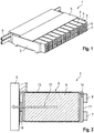
- FIG. 2 shows a schematic simplified representation of a section through the energy storage module 1. The section is placed through one of the energy storage cells 2.
- the housing 8 is formed by a first outer wall 11, a second outer wall 12 and a third outer wall 13.
- the energy storage cell 2 shown is cuboid, so that the third outer wall 13 is formed by four outer surfaces ,
- the first outer wall 11 is designed as a lid and closes the housing 8.
- an electrochemical element 9 is arranged inside the housing 8.
- the electrochemical element 9 is wound up.
- the anodic terminal 10 protrudes through the first outer wall 11 and is electrically conductively connected to the anodic current tap 6.
- the cathodic current tap 7 sits together with the anodic current tap 6 on the first outer wall 11. However, the cathodic terminal 14 is not directly connected to the cathodic current tap 7.
- the current flows from the cathodic connection 14 through the housing, in the example shown via the third outer wall 13, the cathode connection 14 being connected directly to the second outer wall 12. to the cathodic current tap 7.
- the second outer wall 12 of the housing 8 rests directly and flat on a heat transfer surface 15 of the cooling device 5. Between the second outer wall 12 and the heat transfer surface 15, only a very thin film 16 is arranged for electrical insulation.
- the cathodic connection 14 represents a direct thermal connection between the electrochemical element 9 and the second outer wall 12. This makes it possible to dissipate the heat from the electrochemical element 9 very effectively by means of the cooling device 5.
- the resulting heat path is shown schematically by the reference numeral 17.
Description
- Vorliegende Erfindung betrifft eine Energiespeicherzelle sowie ein Energiespeichermodul, in dem mehrere der Energiespeicherzellen zusammengefasst sind. Die Energiespeicherzelle und das Energiespeichermodul dienen insbesondere der Energieversorgung des Antriebs eines Kraftfahrzeugs.
- Herkömmliche Energiespeicherzellen weisen üblicherweise ein Gehäuse auf, in dem zumindest ein elektrochemisches Element aufgenommen ist. Das elektrochemische Element im Inneren des Gehäuses umfasst einen anodischen und einen kathodischen Anschluss. Diese beiden Anschlüsse werden durch das Gehäuse hindurch nach außen geführt und außerhalb des Gehäuses mit einem entsprechenden anodischen und kathodischen Stromabgriff verbunden. Der anodische und kathodische Stromabgriff sitzt auf der Außenfläche des Gehäuses. Üblicherweise umfasst das Gehäuse einen topfförmigen Grundkörper, den sog. "can". Dieser topfförmige Grundkörper ist mittels eines Deckels, der sog. "cap", verschlossen. Auf dem Deckel sitzt der anodische und kathodische Stromabgriff.
WO 2009/110484 A1 offenbart eine derartige Energiespeicherzelle aus dem Stand der Technik. Es ist Aufgabe vorliegender Erfindung, eine Energiespeicherzelle und ein Energiespeichermodul anzugeben, die bei kostengünstiger Herstellung und Montage wartungsarm, betriebssicher und wirkungsgradoptimiert betrieben werden können. Insbesondere ist es Aufgabe vorliegender Erfindung, eine Energiespeicherzelle und zugehöriges Energiespeichermodul anzugeben, bei denen effektiv die Wärme aus den elektrochemischen Elementen nach außen abgeführt werden kann. - Die Lösung dieser Aufgabe erfolgt durch die Merkmale der unabhängigen Ansprüche. Die abhängigen Ansprüche haben vorteilhafte Weiterbildungen der Erfindung zum Gegenstand.
- Somit wird die Aufgabe gelöst durch eine Energiespeicherzelle, umfassend ein elektrisch leitfähiges Gehäuse, zumindest ein im Gehäuse angeordnetes, elektrochemisches Element, einen anodischen Stromabgriff und einen kathodischen Stromabgriff. Im Inneren des Gehäuses ist das elektrochemische Element angeordnet. Dieses Element umfasst einen anodischen Anschluss und einen kathodischen Anschluss. Der anodische Stromabgriff sitzt außen auf dem Gehäuse und ist durch das Gehäuse hindurch direkt mit dem anodischen Anschluss des elektrochemischen Elementes verbunden. Der kathodische Stromabgriff sitzt ebenfalls außen am Gehäuse, ist jedoch nicht direkt mit dem kathodischen Anschluss des elektrochemischen Elementes verbunden. Erfindungsgemäß ist der kathodische Anschluss im Inneren des Gehäuses mit dem Gehäuse kontaktiert. Der kathodische Stromabgriff wiederum ist ebenfalls mit dem Gehäuse kontaktiert, so dass der Strom von dem kathodischen Anschluss über das elektrisch leitende Gehäuse zum kathodischen Stromabgriff fließt. Das Gehäuse umfasst zumindest drei Außenwandungen. Die erste Außenwandung ist von der zweiten Außenwandung beabstandet und die dritte Außenwandung ist so angeordnet, dass sie das Gehäuse verschließt und gleichzeitig die erste Außenwandung mit der zweiten Außenwandung verbindet. Der anodische Stromabgriff ist auf der ersten Außenwandung angeordnet. Der kathodische Stromabgriff ist ebenfalls auf der ersten Außenwandung angeordnet. Im Inneren des Gehäuses ist der kathodische Anschluss mit der zweiten Außenwandung direkt elektrisch und thermisch leitend verbunden. Der kathodische Anschluss im Inneren des Gehäuse, welcher das elektrochemische Element mit der zweiten Außenwandung verbindet, erfüllt gleichzeitig zwei Funktionen: der Stromfluss vom elektrochemischen Element über das Gehäuse zum kathodischen Stromabgriff wird gewährleistet. Gleichzeitig dient der kathodische Anschluss für eine direkte und sehr gut wärmeleitende Verbindung zwischen dem elektrochemischen Element und der zweiten Außenfläche. Erfindungsgemäß kann also die in dem elektrochemischen Element entstehende Wärme über ein metallisches Element, nämlich den kathodischen Anschluss, direkt an die zweite Außenfläche des Gehäuses abgeführt werden. Gleichzeitig ist dabei erfindungsgemäß sichergestellt, dass sich an der zweiten Außenfläche kein Stromabgriff befindet. Deshalb kann die zweite Außenfläche des Gehäuses optimal zur Kühlung der Energiespeicherzelle verwendet werden. Die Energiespeicherzelle wird vorzugsweise in einem Kraftfahrzeug verwendet und dient dort zum alleinigen oder unterstützenden Antrieb des Kraftfahrzeugs über einen Elektromotor.
- Die erfindungsgemäße Energiespeicherzelle ermöglicht es, die Stromabgriffe sehr flexibel auf den verschiedenen Außenwandungen des Gehäuses anzuordnen. Dadurch können die Energiespeicherzellen in verschiedenster Weise zu Modulen zusammengefasst werden, so dass sich ein sehr modularer und platzsparender Aufbau ergibt. Gleichzeitig ist durch die optimale Kühlung ein betriebssicherer und wirkungsgradoptimierter Betrieb der Energiespeicherzellen möglich. Im Rahmen der Anmeldung wird meist von der Kühlung der Energiespeicherzellen gesprochen. Selbstverständlich ist es jedoch auch möglich, über die zweite Außenwandung und den kathodischen Anschluss Wärme zuzuführen.
- Vorteilhafterweise ist vorgesehen, dass die erste Außenwandung des Gehäuses zumindest teilweise durch einen Deckel gebildet ist. Der anodische Stromabgriff wird bevorzugt auf dem Deckel angeordnet. Besonders bevorzugt befindet sich auch der kathodische Stromabgriff auf dem Deckel. Der Deckel ist insbesondere so groß ausgebildet, dass über die entsprechende Öffnung das elektrochemische Element in das Gehäuse eingesetzt werden kann. Wenn der kathodische Stromabgriff auf dem Deckel angeordnet ist, muss der Deckel zumindest teilweise elektrisch leitend sein und elektrisch leitend mit dem Rest des Gehäuses verbunden sein.
- Vorteilhafterweise ist das Gehäuse prismatisch ausgebildet, so dass mehrere der Energiespeicherzellen sehr platzsparend aneinandergereiht werden können. Insbesondere handelt es sich um eine quaderförmige Ausgestaltung, wobei die erste Außenwandung parallel zur zweiten Außenwandung angeordnet ist. Bei einer zylindrischen Ausgestaltung des Gehäuses stehen die erste und zweite Außenwandung ebenfalls parallel und beabstandet zueinander, wobei die dritte Außenwandung die Mantelfläche darstellt.
- Die äußere Fläche der zweiten Außenwandung ist bevorzugt elektrisch isoliert. Zur Isolierung wird hier vorzugsweise eine Folie verwendet. Die Folie sollte äußerst dünn sein und möglichst thermisch leitend ausgebildet sein. Erfindungsgemäß wird an der zweiten Außenwandung die Kühlvorrichtung angesetzt. Da Kühlvorrichtungen meist aus metallischen Werkstoffen ausgebildet sind, erfolgt hier vorteilhafterweise die elektrische Isolierung zwischen Kühlvorrichtung und zweiter Außenwandung.
- Die Erfindung umfasst des Weiteren ein Energiespeichermodul, insbesondere für ein Kraftfahrzeug. Das Energiespeichermodul umfasst zumindest eine der soeben beschriebenen Energiespeicherzellen. Insofern gelten die im Rahmen der Energiespeicherzelle vorgestellten vorteilhaften Ausgestaltungen und Unteransprüche entsprechend auch für das Energiespeichermodul. Darüber hinaus umfasst das Energiespeichermodul eine Kühlvorrichtung mit einer Wärmeübertragungsfläche. Diese Wärmeübertragungsfläche der Kühlvorrichtung liegt flächig an der zweiten Außenwandung der Energiespeicherzelle an. Die vorteilhafte elektrische Isolierung durch die Folie ist bevorzugt zwischen der Wärmeübertragungsfläche und der zweiten Außenwandung angeordnet.
- Bevorzugt ist vorgesehen, dass mehrere der Energiespeicherzellen gestapelt aneinander angeordnet sind, wobei die Wärmeübertragungsfläche einer gemeinsamen Kühlvorrichtung an den mehreren zweiten Außenwandungen der mehreren Energiespeicherzellen anliegt, so dass eine Kühlvorrichtung für mehrere Energiespeicherzellen genutzt werden kann.
- In der Kühlvorrichtung ist bevorzugt eine Fluidführungsvorrichtung angeordnet. Mittels dieser Fluidführungsvorrichtung kann die Wärme von der Wärmeübertragungsfläche über das entsprechende Fluid nach außen abtransportiert werden.
- Die Energiespeicherzelle ist bevorzugt als Lithium-Ionen-Akku ausgebildet.
- Weitere Einzelheiten, Merkmale und Vorteile der Erfindung ergeben sich aus der nachfolgenden Beschreibung und den Figuren. Es zeigen:
- Figur 1
- ein erfindungsgemäßes Energiespeichermodul mit mehreren erfindungsgemäßen Energiespeicherzellen gemäß einem Ausführungsbeispiel, und
- Figur 2
- eine schematische Schnittansicht durch das erfindungsgemäße Energiespeichermodul gemäß dem Ausführungsbeispiel.
- Anhand der
Figuren 1 und 2 wird im Folgenden ein Ausführungsbeispiel eines Energiespeichermoduls 1 gezeigt. In dem Energiespeichermodul 1 sind mehrere Energiespeicherzellen 2 zusammengefasst. Das gezeigte Energiespeichermodul 1 dient zur Spannungsversorgung eines elektrischen Antriebs in einem Kraftfahrzeug. - Wie
Fig. 1 zeigt, sind in dem Energiespeichermodul 1 mehrere prismatische Energiespeicherzellen 2 in einer Reihe nebeneinander gestapelt. Der Stapel aus Energiespeicherzellen 2 wird durch Druckplatten 3 und Zuganker 4 zusammengehalten. Die Zuganker 4 verbinden dabei die Druckplatten 3. - An jeder Energiespeicherzelle 2 ist ein anodischer Stromabgriff 6 und ein kathodischer Stromabgriff 7 ausgebildet. Des Weiteren umfasst das Energiespeichermodul 1 eine gemeinsame Kühlvorrichtung 5. Diese Kühlvorrichtung 5 liegt an der Rückseite aller Energiespeicherzellen 2 an.
-
Figur 2 zeigt in schematisch vereinfachter Darstellung einen Schnitt durch das Energiespeichermodul 1. Der Schnitt ist dabei durch eine der Energiespeicherzellen 2 gelegt. - Wie
Figur 2 zeigt, umfasst die Energiespeicherzelle 2 ein Gehäuse 8. Das Gehäuse 8 ist gebildet durch eine erste Außenwandung 11, eine zweite Außenwandung 12 und eine dritte Außenwandung 13. Die gezeigte Energiespeicherzelle 2 ist quaderförmig ausgebildet, so dass die dritte Außenwandung 13 durch vier Außenflächen gebildet ist. Die erste Außenwandung 11 ist als Deckel ausgebildet und verschließt das Gehäuse 8. - Im Inneren des Gehäuses 8 ist ein elektrochemisches Element 9 angeordnet. Das elektrochemische Element 9 ist gewickelt aufgebaut. An dem elektrochemischen Element 9 befindet sich ein anodischer Anschluss 10 und ein kathodischer Anschluss 14.
- Der anodische Anschluss 10 ragt durch die erste Außenwandung 11 hindurch und ist mit dem anodischen Stromabgriff 6 elektrisch leitend verbunden. Der kathodische Stromabgriff 7 sitzt gemeinsam mit dem anodischen Stromabgriff 6 auf der ersten Außenwandung 11. Allerdings ist der kathodische Anschluss 14 nicht direkt verbunden mit dem kathodischen Stromabgriff 7.
- Wie
Figur 2 zeigt, ist der kathodische Anschluss 14 direkt verbunden mit der zweiten Außenwandung 12 des Gehäuses 8. Dadurch, dass das Gehäuse 8 elektrisch leitend ausgebildet ist, fließt der Strom vom kathodischen Anschluss 14 durch das Gehäuse hindurch, im gezeigten Beispiel über die dritte Außenwandung 13, zum kathodischen Stromabgriff 7. - Die zweite Außenwandung 12 des Gehäuses 8 liegt direkt und flächig auf einer Wärmeübertragungsfläche 15 der Kühlvorrichtung 5 auf. Zwischen der zweiten Außenwandung 12 und der Wärmeübertragungsfläche 15 ist lediglich eine sehr dünne Folie 16 zur elektrischen Isolierung angeordnet.
- Der kathodische Anschluss 14 stellt eine direkte thermische Verbindung zwischen dem elektrochemischen Element 9 und der zweiten Außenwandung 12 dar. Dadurch ist es möglich, mittels der Kühlvorrichtung 5 äußerst effektiv die Wärme aus dem elektrochemischen Element 9 abzuführen. Der sich ergebende Wärmepfad ist mit dem Bezugszeichen 17 schematisch eingezeichnet.
- Gleichzeitig zu diesem optimalen Wärmepfad 17 erlaubt die direkte Kontaktierung des Gehäuses 8 über den kathodischen Anschluss 14 ein annähernd beliebiges Setzen des kathodischen Stromabgriffes 7 auf der Gehäuseoberfläche 8.
-
- 1
- Energiespeichermodul
- 2
- Energiespeicherzelle
- 3
- Druckplatte
- 4
- Zuganker
- 5
- Kühlvorrichtung
- 6
- anodischer Stromabgriff
- 7
- kathodischer Stromabgriff
- 8
- Gehäuse
- 9
- elektrochemisches Element
- 10
- anodischer Anschluss
- 11
- erste Außenwandung
- 12
- zweite Außenwandung
- 13
- dritte Außenwandung
- 14
- kathodischer Anschluss
- 15
- Wärmeübertragungsfläche
- 16
- Folie
- 17
- Wärmeleitpfad
Claims (9)
- Energiespeicherzelle (2), umfassend:- ein elektrisch leitfähiges Gehäuse (8) mit zumindest einer ersten, zweiten und dritten Außenwandung (11, 12, 13), wobei die erste Außehwandung (11) von der zweiten Außenwandung (12) beabstandet ist, und wobei die dritte Außenwandung (13) die erste und zweite Außenwandung (11, 12) miteinander verbindet,- zumindest ein im Gehäuse (8) angeordnetes, elektrochemisches Element (9) mit einem anodischen Anschluss (10) und einem kathodischen Anschluss (14),- einen elektrisch leitend mit dem anodischen Anschluss (10) verbundenen anodischen Stromabgriff (6) auf der ersten Außenwandung (11), und- einen elektrisch leitend mit der ersten oder dritten Außenwandung (11, 13) verbundenen kathodischen Stromabgriff (7), dadurch gekennzeichnet,- dass der kathodische Anschluss (14) im Inneren des Gehäuses (8) direkt mit der zweiten Außenwandung (12) elektrisch und thermisch leitend verbunden ist, wobei der kathodische Stromabgriff (7) auf der ersten Außenwandung (11) sitzt, wobei der Stromfluss ausgehend von dem kathodischen Anschluss (14) über die zweite Außenwandung (12), die dritte Außenwandung (13) und die erste Außenwandung (11) zu dem kathodischen Stromabgriff (7) erfolgt.
- Energiespeicherzelle nach Anspruch 1, dadurch gekennzeichnet, dass die erste Außenwandung (11) des Gehäuses (8) zumindest teilweise durch einen Deckel gebildet ist, wobei der anodische Stromabgriff (6) auf dem Deckel angeordnet ist.
- Energiespeicherzelle nach Anspruch 2, dadurch gekennzeichnet, dass der kathodische Stromabgriff (7) auf dem Deckel angeordnet ist.
- Energiespeicherzelle nach einem der vorhergehenden Ansprüche, dadurch gekennzeichnet, dass das Gehäuse (8) prismatisch, insbesondere quaderförmig, ausgebildet ist.
- Energiespeicherzelle nach einem der vorhergehenden Ansprüche, dadurch gekennzeichnet, dass die erste Außenwandung (11) parallel zur zweiten Außenwandung (12) angeordnet ist.
- Energiespeicherzelle nach einem der vorhergehenden Ansprüche, dadurch gekennzeichnet, dass eine Außenfläche der zweiten Außenwandung (12), vorzugsweise durch eine Folie (16), elektrisch isoliert ist.
- Energiespeichermodul (1), insbesondere für ein Kraftfahrzeug, umfassend:- zumindest eine Energiespeicherzelle (2) nach einem der vorhergehenden Ansprüche, und- eine Kühlvorrichtung (5) mit einer Wärmeübertragungsfläche (15),- wobei die Wärmeübertragungsfläche (15) an der zweiten Außenwandung (12) der Energiespeicherzelle (2) anliegt
- Energiespeichermodul nach Anspruch 7, dadurch gekennzeichnet, dass mehrere der Energiespeicherzellen (2) gestapelt sind, wobei die Wärmeübertragungsfläche (15) der einen Kühlvorrichtung (5) an den zweiten Außenwandungen (12) der mehreren Energiespeicherzellen I2 anliegt.
- Energiespeichermodul nach Anspruch 7 oder 8, gekennzeichnet durch eine Fluidführungsvorrichtung in der Kühlvorrichtung (5) zum Abführen der Wärme von der Wärmeübertragungsfläche (15).
Applications Claiming Priority (2)
| Application Number | Priority Date | Filing Date | Title |
|---|---|---|---|
| DE201210218991 DE102012218991A1 (de) | 2012-10-18 | 2012-10-18 | Energiespeicherzelle und Energiespeichermodul |
| PCT/EP2013/069194 WO2014060165A1 (de) | 2012-10-18 | 2013-09-17 | Energiespeicherzelle und energiespeichermodul |
Publications (2)
| Publication Number | Publication Date |
|---|---|
| EP2909873A1 EP2909873A1 (de) | 2015-08-26 |
| EP2909873B1 true EP2909873B1 (de) | 2017-06-28 |
Family
ID=49209359
Family Applications (1)
| Application Number | Title | Priority Date | Filing Date |
|---|---|---|---|
| EP13763052.1A Active EP2909873B1 (de) | 2012-10-18 | 2013-09-17 | Energiespeicherzelle und energiespeichermodul |
Country Status (7)
| Country | Link |
|---|---|
| US (1) | US10319961B2 (de) |
| EP (1) | EP2909873B1 (de) |
| JP (1) | JP2015536526A (de) |
| KR (1) | KR20150070098A (de) |
| CN (1) | CN104584258A (de) |
| DE (1) | DE102012218991A1 (de) |
| WO (1) | WO2014060165A1 (de) |
Families Citing this family (3)
| Publication number | Priority date | Publication date | Assignee | Title |
|---|---|---|---|---|
| DE102013225350A1 (de) * | 2013-12-10 | 2015-06-11 | Robert Bosch Gmbh | Anbindung einer Batteriezelle an ein Gehäuse |
| DE102016205270A1 (de) * | 2016-03-31 | 2017-10-05 | Robert Bosch Gmbh | Batteriemodul |
| DE102016206334A1 (de) | 2016-04-15 | 2017-10-19 | Bayerische Motoren Werke Aktiengesellschaft | Energiespeicherzellengehäuse, Engergiespeicherzele und Verfahren zu deren Herstellung |
Family Cites Families (13)
| Publication number | Priority date | Publication date | Assignee | Title |
|---|---|---|---|---|
| US6294287B1 (en) * | 1999-08-18 | 2001-09-25 | The Gillette Company | Alkaline cell with insulator |
| US7045247B1 (en) * | 2000-08-24 | 2006-05-16 | The Gillette Company | Battery cathode |
| JP4056279B2 (ja) * | 2002-03-29 | 2008-03-05 | 松下電器産業株式会社 | 電池 |
| JP4184927B2 (ja) * | 2002-12-27 | 2008-11-19 | 三星エスディアイ株式会社 | 2次電池及びその製造方法 |
| US20060046135A1 (en) * | 2004-08-27 | 2006-03-02 | Weiwei Huang | Alkaline battery with MnO2/NiOOH active material |
| KR100648731B1 (ko) * | 2005-03-21 | 2006-11-23 | 삼성에스디아이 주식회사 | 이차전지 및 이의 제조 방법 |
| WO2008099602A1 (ja) * | 2007-02-16 | 2008-08-21 | Panasonic Corporation | 蓄電ユニット |
| JP5321783B2 (ja) * | 2008-03-04 | 2013-10-23 | 株式会社東芝 | 非水電解質二次電池および組電池 |
| JP5417932B2 (ja) * | 2008-08-07 | 2014-02-19 | 三洋電機株式会社 | 車両用の電源装置 |
| DE102008059956B4 (de) * | 2008-12-02 | 2012-09-06 | Daimler Ag | Batterie, insbesondere Fahrzeugbatterie |
| JP2011014297A (ja) * | 2009-06-30 | 2011-01-20 | Panasonic Corp | 捲回型電極群および電池 |
| JP5804323B2 (ja) * | 2011-01-07 | 2015-11-04 | 株式会社Gsユアサ | 蓄電素子及び蓄電装置 |
| CN202167571U (zh) * | 2011-07-21 | 2012-03-14 | 南通尧盛钢结构有限公司 | 一种叠层电池 |
-
2012
- 2012-10-18 DE DE201210218991 patent/DE102012218991A1/de not_active Withdrawn
-
2013
- 2013-09-17 EP EP13763052.1A patent/EP2909873B1/de active Active
- 2013-09-17 WO PCT/EP2013/069194 patent/WO2014060165A1/de active Application Filing
- 2013-09-17 JP JP2015537176A patent/JP2015536526A/ja active Pending
- 2013-09-17 CN CN201380043028.7A patent/CN104584258A/zh active Pending
- 2013-09-17 KR KR1020157006138A patent/KR20150070098A/ko not_active Application Discontinuation
-
2015
- 2015-04-17 US US14/689,598 patent/US10319961B2/en active Active
Non-Patent Citations (1)
| Title |
|---|
| None * |
Also Published As
| Publication number | Publication date |
|---|---|
| CN104584258A (zh) | 2015-04-29 |
| US20150221906A1 (en) | 2015-08-06 |
| JP2015536526A (ja) | 2015-12-21 |
| US10319961B2 (en) | 2019-06-11 |
| KR20150070098A (ko) | 2015-06-24 |
| EP2909873A1 (de) | 2015-08-26 |
| WO2014060165A1 (de) | 2014-04-24 |
| DE102012218991A1 (de) | 2014-06-12 |
Similar Documents
| Publication | Publication Date | Title |
|---|---|---|
| EP3739660B1 (de) | Batteriemodul für ein kraftfahrzeug | |
| EP2854211A1 (de) | Heiz- und Kühlvorrichtung für eine Batterie | |
| DE102014207403A1 (de) | Batterieeinheit mit einer Aufnahmeeinrichtung und einer Mehrzahl von elektrochemischen Zellen sowie Batteriemodul mit einer Mehrzahl von solchen Batterieeinheiten | |
| EP2243178A1 (de) | Batterie mit mehreren einzelzellen | |
| WO2019161876A1 (de) | Mechanisches und thermisches system für eine modulare batterie mit leistungselektronikkomponenten | |
| DE102008034868A1 (de) | Batterie mit einer in einem Batteriegehäuse angeordneten Wärmeleitplatte zum Temperieren der Batterie | |
| WO2011116801A1 (de) | Batterie aus einer vielzahl von batterieeinzelzellen | |
| DE102014203715A1 (de) | Effizient kühlbares Gehäuse für ein Batteriemodul | |
| DE102007063269A1 (de) | Batteriemodul mit mehreren Einzelzellen | |
| DE102014218377A1 (de) | Temperiereinrichtung zur Temperierung einer elektrischen Energieversorgungseinheit | |
| DE102019119242A1 (de) | Akkupack | |
| DE112016004706T5 (de) | Vorrichtung umfassend batteriezellen und ein verfahren zum zusammenbauen | |
| DE102011075614A1 (de) | Leistungselektronisches System mit Flüssigkeitskühleinrichtung | |
| EP2909873B1 (de) | Energiespeicherzelle und energiespeichermodul | |
| DE102009034675A1 (de) | Elektrochemischer Energiespeicher und Verfahren zum Kühlen oder Erwärmen eines elektrochemischen Energiespeichers | |
| EP2676281B1 (de) | Anordnung mit einem gehäuse | |
| DE112013005053T5 (de) | Energiespeicherungsmodul und Energiespeicherungsvorrichtung | |
| DE102009035494A1 (de) | Hochvoltbatterie | |
| DE102014202549A1 (de) | Elektrische Energiespeichereinrichtung und Verfahren zum Entwärmen einer elektrischen Energiespeichereinrichtung | |
| DE102014205724A1 (de) | Energiespeichervorrichtung | |
| EP3465797B1 (de) | Batterie mit batterieabschnitten und kontaktierungsabschnittselement | |
| WO2018197276A1 (de) | Deckel zum elektrischen koppeln mehrerer speicherzellen eines elektrischen energiespeichermoduls | |
| DE102018000112A1 (de) | Batterie mit einer Mehrzahl von Batteriezellen | |
| WO2022194470A1 (de) | Kühleinrichtung mit einem kühlkörper und zwischenkühlelementen, elektrischer energiespeicher sowie kraftfahrzeug | |
| DE102014202547A1 (de) | Elektrische Energiespeicherzelle und Verfahren zum Entwärmen einer elektrischen Energiespeicherzelle |
Legal Events
| Date | Code | Title | Description |
|---|---|---|---|
| PUAI | Public reference made under article 153(3) epc to a published international application that has entered the european phase |
Free format text: ORIGINAL CODE: 0009012 |
|
| 17P | Request for examination filed |
Effective date: 20150212 |
|
| AK | Designated contracting states |
Kind code of ref document: A1 Designated state(s): AL AT BE BG CH CY CZ DE DK EE ES FI FR GB GR HR HU IE IS IT LI LT LU LV MC MK MT NL NO PL PT RO RS SE SI SK SM TR |
|
| AX | Request for extension of the european patent |
Extension state: BA ME |
|
| DAX | Request for extension of the european patent (deleted) | ||
| REG | Reference to a national code |
Ref country code: DE Ref legal event code: R079 Ref document number: 502013007648 Country of ref document: DE Free format text: PREVIOUS MAIN CLASS: H01M0002020000 Ipc: H01M0010625000 |
|
| GRAP | Despatch of communication of intention to grant a patent |
Free format text: ORIGINAL CODE: EPIDOSNIGR1 |
|
| STAA | Information on the status of an ep patent application or granted ep patent |
Free format text: STATUS: GRANT OF PATENT IS INTENDED |
|
| RIC1 | Information provided on ipc code assigned before grant |
Ipc: H01M 2/02 20060101ALI20170301BHEP Ipc: H01M 10/6556 20140101ALI20170301BHEP Ipc: H01M 10/625 20140101AFI20170301BHEP Ipc: H01M 2/30 20060101ALI20170301BHEP Ipc: H01M 2/10 20060101ALI20170301BHEP Ipc: H01M 10/6553 20140101ALI20170301BHEP Ipc: H01M 10/647 20140101ALI20170301BHEP Ipc: H01M 10/613 20140101ALI20170301BHEP Ipc: H01M 10/6554 20140101ALI20170301BHEP Ipc: H01M 2/26 20060101ALI20170301BHEP |
|
| INTG | Intention to grant announced |
Effective date: 20170315 |
|
| GRAS | Grant fee paid |
Free format text: ORIGINAL CODE: EPIDOSNIGR3 |
|
| GRAA | (expected) grant |
Free format text: ORIGINAL CODE: 0009210 |
|
| STAA | Information on the status of an ep patent application or granted ep patent |
Free format text: STATUS: THE PATENT HAS BEEN GRANTED |
|
| AK | Designated contracting states |
Kind code of ref document: B1 Designated state(s): AL AT BE BG CH CY CZ DE DK EE ES FI FR GB GR HR HU IE IS IT LI LT LU LV MC MK MT NL NO PL PT RO RS SE SI SK SM TR |
|
| REG | Reference to a national code |
Ref country code: GB Ref legal event code: FG4D Free format text: NOT ENGLISH |
|
| REG | Reference to a national code |
Ref country code: CH Ref legal event code: EP |
|
| REG | Reference to a national code |
Ref country code: AT Ref legal event code: REF Ref document number: 905594 Country of ref document: AT Kind code of ref document: T Effective date: 20170715 |
|
| REG | Reference to a national code |
Ref country code: IE Ref legal event code: FG4D Free format text: LANGUAGE OF EP DOCUMENT: GERMAN |
|
| REG | Reference to a national code |
Ref country code: DE Ref legal event code: R096 Ref document number: 502013007648 Country of ref document: DE |
|
| REG | Reference to a national code |
Ref country code: FR Ref legal event code: PLFP Year of fee payment: 5 |
|
| PG25 | Lapsed in a contracting state [announced via postgrant information from national office to epo] |
Ref country code: NO Free format text: LAPSE BECAUSE OF FAILURE TO SUBMIT A TRANSLATION OF THE DESCRIPTION OR TO PAY THE FEE WITHIN THE PRESCRIBED TIME-LIMIT Effective date: 20170928 Ref country code: FI Free format text: LAPSE BECAUSE OF FAILURE TO SUBMIT A TRANSLATION OF THE DESCRIPTION OR TO PAY THE FEE WITHIN THE PRESCRIBED TIME-LIMIT Effective date: 20170628 Ref country code: HR Free format text: LAPSE BECAUSE OF FAILURE TO SUBMIT A TRANSLATION OF THE DESCRIPTION OR TO PAY THE FEE WITHIN THE PRESCRIBED TIME-LIMIT Effective date: 20170628 Ref country code: LT Free format text: LAPSE BECAUSE OF FAILURE TO SUBMIT A TRANSLATION OF THE DESCRIPTION OR TO PAY THE FEE WITHIN THE PRESCRIBED TIME-LIMIT Effective date: 20170628 Ref country code: GR Free format text: LAPSE BECAUSE OF FAILURE TO SUBMIT A TRANSLATION OF THE DESCRIPTION OR TO PAY THE FEE WITHIN THE PRESCRIBED TIME-LIMIT Effective date: 20170929 |
|
| REG | Reference to a national code |
Ref country code: NL Ref legal event code: MP Effective date: 20170628 |
|
| REG | Reference to a national code |
Ref country code: LT Ref legal event code: MG4D |
|
| PG25 | Lapsed in a contracting state [announced via postgrant information from national office to epo] |
Ref country code: RS Free format text: LAPSE BECAUSE OF FAILURE TO SUBMIT A TRANSLATION OF THE DESCRIPTION OR TO PAY THE FEE WITHIN THE PRESCRIBED TIME-LIMIT Effective date: 20170628 Ref country code: BG Free format text: LAPSE BECAUSE OF FAILURE TO SUBMIT A TRANSLATION OF THE DESCRIPTION OR TO PAY THE FEE WITHIN THE PRESCRIBED TIME-LIMIT Effective date: 20170928 Ref country code: SE Free format text: LAPSE BECAUSE OF FAILURE TO SUBMIT A TRANSLATION OF THE DESCRIPTION OR TO PAY THE FEE WITHIN THE PRESCRIBED TIME-LIMIT Effective date: 20170628 Ref country code: NL Free format text: LAPSE BECAUSE OF FAILURE TO SUBMIT A TRANSLATION OF THE DESCRIPTION OR TO PAY THE FEE WITHIN THE PRESCRIBED TIME-LIMIT Effective date: 20170628 Ref country code: LV Free format text: LAPSE BECAUSE OF FAILURE TO SUBMIT A TRANSLATION OF THE DESCRIPTION OR TO PAY THE FEE WITHIN THE PRESCRIBED TIME-LIMIT Effective date: 20170628 |
|
| PG25 | Lapsed in a contracting state [announced via postgrant information from national office to epo] |
Ref country code: CZ Free format text: LAPSE BECAUSE OF FAILURE TO SUBMIT A TRANSLATION OF THE DESCRIPTION OR TO PAY THE FEE WITHIN THE PRESCRIBED TIME-LIMIT Effective date: 20170628 Ref country code: EE Free format text: LAPSE BECAUSE OF FAILURE TO SUBMIT A TRANSLATION OF THE DESCRIPTION OR TO PAY THE FEE WITHIN THE PRESCRIBED TIME-LIMIT Effective date: 20170628 Ref country code: RO Free format text: LAPSE BECAUSE OF FAILURE TO SUBMIT A TRANSLATION OF THE DESCRIPTION OR TO PAY THE FEE WITHIN THE PRESCRIBED TIME-LIMIT Effective date: 20170628 Ref country code: SK Free format text: LAPSE BECAUSE OF FAILURE TO SUBMIT A TRANSLATION OF THE DESCRIPTION OR TO PAY THE FEE WITHIN THE PRESCRIBED TIME-LIMIT Effective date: 20170628 |
|
| PG25 | Lapsed in a contracting state [announced via postgrant information from national office to epo] |
Ref country code: IS Free format text: LAPSE BECAUSE OF FAILURE TO SUBMIT A TRANSLATION OF THE DESCRIPTION OR TO PAY THE FEE WITHIN THE PRESCRIBED TIME-LIMIT Effective date: 20171028 Ref country code: PL Free format text: LAPSE BECAUSE OF FAILURE TO SUBMIT A TRANSLATION OF THE DESCRIPTION OR TO PAY THE FEE WITHIN THE PRESCRIBED TIME-LIMIT Effective date: 20170628 Ref country code: ES Free format text: LAPSE BECAUSE OF FAILURE TO SUBMIT A TRANSLATION OF THE DESCRIPTION OR TO PAY THE FEE WITHIN THE PRESCRIBED TIME-LIMIT Effective date: 20170628 Ref country code: SM Free format text: LAPSE BECAUSE OF FAILURE TO SUBMIT A TRANSLATION OF THE DESCRIPTION OR TO PAY THE FEE WITHIN THE PRESCRIBED TIME-LIMIT Effective date: 20170628 |
|
| REG | Reference to a national code |
Ref country code: DE Ref legal event code: R097 Ref document number: 502013007648 Country of ref document: DE |
|
| PG25 | Lapsed in a contracting state [announced via postgrant information from national office to epo] |
Ref country code: DK Free format text: LAPSE BECAUSE OF FAILURE TO SUBMIT A TRANSLATION OF THE DESCRIPTION OR TO PAY THE FEE WITHIN THE PRESCRIBED TIME-LIMIT Effective date: 20170628 |
|
| REG | Reference to a national code |
Ref country code: CH Ref legal event code: PL |
|
| PLBE | No opposition filed within time limit |
Free format text: ORIGINAL CODE: 0009261 |
|
| STAA | Information on the status of an ep patent application or granted ep patent |
Free format text: STATUS: NO OPPOSITION FILED WITHIN TIME LIMIT |
|
| PG25 | Lapsed in a contracting state [announced via postgrant information from national office to epo] |
Ref country code: MC Free format text: LAPSE BECAUSE OF FAILURE TO SUBMIT A TRANSLATION OF THE DESCRIPTION OR TO PAY THE FEE WITHIN THE PRESCRIBED TIME-LIMIT Effective date: 20170628 |
|
| 26N | No opposition filed |
Effective date: 20180329 |
|
| REG | Reference to a national code |
Ref country code: IE Ref legal event code: MM4A |
|
| REG | Reference to a national code |
Ref country code: BE Ref legal event code: MM Effective date: 20170930 |
|
| PG25 | Lapsed in a contracting state [announced via postgrant information from national office to epo] |
Ref country code: LU Free format text: LAPSE BECAUSE OF NON-PAYMENT OF DUE FEES Effective date: 20170917 |
|
| PG25 | Lapsed in a contracting state [announced via postgrant information from national office to epo] |
Ref country code: LI Free format text: LAPSE BECAUSE OF NON-PAYMENT OF DUE FEES Effective date: 20170930 Ref country code: IE Free format text: LAPSE BECAUSE OF NON-PAYMENT OF DUE FEES Effective date: 20170917 Ref country code: CH Free format text: LAPSE BECAUSE OF NON-PAYMENT OF DUE FEES Effective date: 20170930 |
|
| PG25 | Lapsed in a contracting state [announced via postgrant information from national office to epo] |
Ref country code: SI Free format text: LAPSE BECAUSE OF FAILURE TO SUBMIT A TRANSLATION OF THE DESCRIPTION OR TO PAY THE FEE WITHIN THE PRESCRIBED TIME-LIMIT Effective date: 20170628 Ref country code: BE Free format text: LAPSE BECAUSE OF NON-PAYMENT OF DUE FEES Effective date: 20170930 |
|
| REG | Reference to a national code |
Ref country code: FR Ref legal event code: PLFP Year of fee payment: 6 |
|
| PG25 | Lapsed in a contracting state [announced via postgrant information from national office to epo] |
Ref country code: MT Free format text: LAPSE BECAUSE OF FAILURE TO SUBMIT A TRANSLATION OF THE DESCRIPTION OR TO PAY THE FEE WITHIN THE PRESCRIBED TIME-LIMIT Effective date: 20170628 |
|
| PG25 | Lapsed in a contracting state [announced via postgrant information from national office to epo] |
Ref country code: HU Free format text: LAPSE BECAUSE OF FAILURE TO SUBMIT A TRANSLATION OF THE DESCRIPTION OR TO PAY THE FEE WITHIN THE PRESCRIBED TIME-LIMIT; INVALID AB INITIO Effective date: 20130917 |
|
| PG25 | Lapsed in a contracting state [announced via postgrant information from national office to epo] |
Ref country code: CY Free format text: LAPSE BECAUSE OF FAILURE TO SUBMIT A TRANSLATION OF THE DESCRIPTION OR TO PAY THE FEE WITHIN THE PRESCRIBED TIME-LIMIT Effective date: 20170628 |
|
| REG | Reference to a national code |
Ref country code: AT Ref legal event code: MM01 Ref document number: 905594 Country of ref document: AT Kind code of ref document: T Effective date: 20180917 |
|
| PG25 | Lapsed in a contracting state [announced via postgrant information from national office to epo] |
Ref country code: MK Free format text: LAPSE BECAUSE OF FAILURE TO SUBMIT A TRANSLATION OF THE DESCRIPTION OR TO PAY THE FEE WITHIN THE PRESCRIBED TIME-LIMIT Effective date: 20170628 |
|
| PG25 | Lapsed in a contracting state [announced via postgrant information from national office to epo] |
Ref country code: AT Free format text: LAPSE BECAUSE OF NON-PAYMENT OF DUE FEES Effective date: 20180917 |
|
| PG25 | Lapsed in a contracting state [announced via postgrant information from national office to epo] |
Ref country code: TR Free format text: LAPSE BECAUSE OF FAILURE TO SUBMIT A TRANSLATION OF THE DESCRIPTION OR TO PAY THE FEE WITHIN THE PRESCRIBED TIME-LIMIT Effective date: 20170628 |
|
| PG25 | Lapsed in a contracting state [announced via postgrant information from national office to epo] |
Ref country code: PT Free format text: LAPSE BECAUSE OF FAILURE TO SUBMIT A TRANSLATION OF THE DESCRIPTION OR TO PAY THE FEE WITHIN THE PRESCRIBED TIME-LIMIT Effective date: 20170628 |
|
| PG25 | Lapsed in a contracting state [announced via postgrant information from national office to epo] |
Ref country code: AL Free format text: LAPSE BECAUSE OF FAILURE TO SUBMIT A TRANSLATION OF THE DESCRIPTION OR TO PAY THE FEE WITHIN THE PRESCRIBED TIME-LIMIT Effective date: 20170628 |
|
| STAA | Information on the status of an ep patent application or granted ep patent |
Free format text: STATUS: NO OPPOSITION FILED WITHIN TIME LIMIT |
|
| P01 | Opt-out of the competence of the unified patent court (upc) registered |
Effective date: 20230502 |
|
| PGFP | Annual fee paid to national office [announced via postgrant information from national office to epo] |
Ref country code: GB Payment date: 20230921 Year of fee payment: 11 |
|
| PGFP | Annual fee paid to national office [announced via postgrant information from national office to epo] |
Ref country code: FR Payment date: 20230918 Year of fee payment: 11 Ref country code: DE Payment date: 20230912 Year of fee payment: 11 |
|
| PGFP | Annual fee paid to national office [announced via postgrant information from national office to epo] |
Ref country code: IT Payment date: 20230929 Year of fee payment: 11 |