EP2909568B1 - Innovatives befehls- und steuerungssystem zum zielen und abfeuern für militärische landfahrzeuge mit mindestens einer waffe - Google Patents
Innovatives befehls- und steuerungssystem zum zielen und abfeuern für militärische landfahrzeuge mit mindestens einer waffe Download PDFInfo
- Publication number
- EP2909568B1 EP2909568B1 EP13818386.8A EP13818386A EP2909568B1 EP 2909568 B1 EP2909568 B1 EP 2909568B1 EP 13818386 A EP13818386 A EP 13818386A EP 2909568 B1 EP2909568 B1 EP 2909568B1
- Authority
- EP
- European Patent Office
- Prior art keywords
- aiming
- firing
- control
- command
- user interface
- Prior art date
- Legal status (The legal status is an assumption and is not a legal conclusion. Google has not performed a legal analysis and makes no representation as to the accuracy of the status listed.)
- Not-in-force
Links
- 238000010304 firing Methods 0.000 title claims description 184
- 238000004891 communication Methods 0.000 claims description 37
- NIOPZPCMRQGZCE-WEVVVXLNSA-N 2,4-dinitro-6-(octan-2-yl)phenyl (E)-but-2-enoate Chemical compound CCCCCCC(C)C1=CC([N+]([O-])=O)=CC([N+]([O-])=O)=C1OC(=O)\C=C\C NIOPZPCMRQGZCE-WEVVVXLNSA-N 0.000 claims description 15
- 238000005516 engineering process Methods 0.000 claims description 3
- 230000003595 spectral effect Effects 0.000 description 11
- 238000012986 modification Methods 0.000 description 2
- 230000004048 modification Effects 0.000 description 2
- 238000012360 testing method Methods 0.000 description 2
- 230000005540 biological transmission Effects 0.000 description 1
- 238000011161 development Methods 0.000 description 1
- 238000010586 diagram Methods 0.000 description 1
- 230000007257 malfunction Effects 0.000 description 1
- 238000000034 method Methods 0.000 description 1
Images
Classifications
-
- F—MECHANICAL ENGINEERING; LIGHTING; HEATING; WEAPONS; BLASTING
- F41—WEAPONS
- F41G—WEAPON SIGHTS; AIMING
- F41G3/00—Aiming or laying means
- F41G3/14—Indirect aiming means
- F41G3/16—Sighting devices adapted for indirect laying of fire
- F41G3/165—Sighting devices adapted for indirect laying of fire using a TV-monitor
-
- F—MECHANICAL ENGINEERING; LIGHTING; HEATING; WEAPONS; BLASTING
- F41—WEAPONS
- F41G—WEAPON SIGHTS; AIMING
- F41G3/00—Aiming or laying means
- F41G3/14—Indirect aiming means
- F41G3/16—Sighting devices adapted for indirect laying of fire
-
- B—PERFORMING OPERATIONS; TRANSPORTING
- B60—VEHICLES IN GENERAL
- B60R—VEHICLES, VEHICLE FITTINGS, OR VEHICLE PARTS, NOT OTHERWISE PROVIDED FOR
- B60R16/00—Electric or fluid circuits specially adapted for vehicles and not otherwise provided for; Arrangement of elements of electric or fluid circuits specially adapted for vehicles and not otherwise provided for
- B60R16/02—Electric or fluid circuits specially adapted for vehicles and not otherwise provided for; Arrangement of elements of electric or fluid circuits specially adapted for vehicles and not otherwise provided for electric constitutive elements
- B60R16/023—Electric or fluid circuits specially adapted for vehicles and not otherwise provided for; Arrangement of elements of electric or fluid circuits specially adapted for vehicles and not otherwise provided for electric constitutive elements for transmission of signals between vehicle parts or subsystems
-
- F—MECHANICAL ENGINEERING; LIGHTING; HEATING; WEAPONS; BLASTING
- F41—WEAPONS
- F41G—WEAPON SIGHTS; AIMING
- F41G3/00—Aiming or laying means
- F41G3/22—Aiming or laying means for vehicle-borne armament, e.g. on aircraft
-
- G—PHYSICS
- G05—CONTROLLING; REGULATING
- G05B—CONTROL OR REGULATING SYSTEMS IN GENERAL; FUNCTIONAL ELEMENTS OF SUCH SYSTEMS; MONITORING OR TESTING ARRANGEMENTS FOR SUCH SYSTEMS OR ELEMENTS
- G05B15/00—Systems controlled by a computer
- G05B15/02—Systems controlled by a computer electric
-
- B—PERFORMING OPERATIONS; TRANSPORTING
- B60—VEHICLES IN GENERAL
- B60R—VEHICLES, VEHICLE FITTINGS, OR VEHICLE PARTS, NOT OTHERWISE PROVIDED FOR
- B60R2300/00—Details of viewing arrangements using cameras and displays, specially adapted for use in a vehicle
- B60R2300/80—Details of viewing arrangements using cameras and displays, specially adapted for use in a vehicle characterised by the intended use of the viewing arrangement
Definitions
- the present invention relates to an innovative system of command and control and of aiming and firing for military land vehicles equipped with at least one weapon, such as, for example, tanks, infantry combat vehicles, etc.
- the present invention regards a system of command and control and of aiming and firing comprising two or more user interfaces capable of dynamically changing the operational role performed, between that of command and control and that of aiming and firing.
- military land vehicles are generally equipped with external vision systems configured to capture video streams, or rather sequences of images, of the outside surroundings.
- many military land vehicles are equipped with daytime vision systems configured to capture video streams of the outside surroundings in the visible spectral band (namely at wavelengths in the range between approximately 380/400 nm and 700/750 nm) and night-time vision systems configured to capture video streams of the outside surroundings in the infrared spectral band (namely at mid-infrared wavelengths in the range between 3 and 5 ⁇ m and far-infrared wavelengths in the range between 8 and 12 ⁇ m).
- an external vision system of a military land vehicle comprises:
- an external vision system of a military land vehicle is generally coupled to a respective user interface that is installed inside the crew compartment of the military land vehicle, is connected to said external vision system to receive the captured video streams and is configured to enable a user to control the operation of said external vision system and to display of a video stream received from said external vision system.
- s user interface for an external vision system of a military land vehicle conveniently comprises:
- the user interface can be installed in various positions inside the crew compartment of the military vehicle, for example, in the commander's station of the military vehicle.
- the respective external vision system could be conveniently called external vision system for command and control.
- an external vision system is operationally associated with said weapon so as to enable an artilleryman/gunner to control the aiming and firing.
- the user interface of the external vision system is conveniently installed inside the crew compartment of the military vehicle in an artilleryman's/gunner's station and is generally called an aiming and firing user interface.
- the external vision system that is operationally associated with a weapon so as to enable controlling the aiming and firing can be conveniently called external vision system for aiming and firing.
- military land vehicles are also generally equipped with so-called "close-defence” perimeter sensors that enable having a complete view of the perimeter around the military vehicle.
- perimeter sensors can conveniently comprise video capture devices that operate in the visible and/or infrared (IR) spectral bands.
- the command and control user interface and the aiming and firing user interface are designed to control only the respective external vision system to which they are coupled.
- the commander of a military land vehicle observes the situation outside the military vehicle via the command and control user interface and, if necessary, designates the targets that are to be fired upon, while an artilleryman/gunner handles the aiming at targets designated by the commander and the shot, or firing, against said targets via the aiming and firing user interface.
- one of the two user interfaces becomes damaged (for example, because it is hit during combat), it is no longer possible to operate the respective external vision system coupled to said damaged user interface.
- the aiming and firing user interface is damaged, it is no longer possible to operate the weapon controlled by said damaged aiming and firing user interface.
- the object of the present invention is therefore that of providing a system capable of solving the previously described drawbacks of current user interfaces for command and control and for aiming and firing.
- the present invention concerns a system of command and control and of aiming and firing that is designed to be installed on board a military land vehicle equipped with at least one weapon and which comprises:
- the present invention concerns a system for military land vehicles equipped with at least one weapon in which the user interfaces of the external vision systems are universal, or rather are utilizable both for observation and designation duties and for aiming and firing duties.
- a user interface whether originally dedicated to the control of an external vision system for command and control, i.e. used for observation and designation duties, or to the control of an external vision system for aiming and firing a weapon, i.e. used for weapon aiming and firing duties, can change its operational role at any time, assuming that of the other user interface present on board the military land vehicle.
- a user interface originally dedicated to the control of an external vision system for command and control i.e. used for observation and designation duties
- a user interface originally dedicated to the control of an external vision system for aiming and firing a weapon i.e. used for weapon aiming and firing duties
- can take control of an external vision system for command and control at any time i.e. can be used for observation and designation duties.
- the different user interfaces are able to dynamically change their operational role so as to enable both the commander and an artilleryman/gunner to operate on the other external vision system in the case where the assigned operator cannot do so, for example, in the case where the commander or an artilleryman/gunner is unable to perform his/her duties because of being wounded, or in the case where one of the user interfaces is damaged.
- the change of operational role is implemented electronically by placing the different external vision systems and the various user interfaces in communication with each other via a deterministic communications bus, preferably based on SERCOS (SErial Real-time COmmunications System) technology of the third generation (i.e. SERCOS III).
- SERCOS SErial Real-time COmmunications System
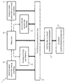
- the attached figure shows a block diagram that represents an example architecture of a system of command and control and of aiming and firing (indicated as a whole by reference numeral 1) produced according to a preferred embodiment of the present invention and installed on a military land vehicle (not shown in the attached figure for simplicity of illustration) equipped with at least one weapon.
- system of command and control and of aiming and firing 1 comprises:
- the interconnection between the various systems/devices/equipment i.e., the external vision system for aiming and firing 10, the external vision system for command and control 11, the video unit 12, the aiming and firing user interface 13, the command and control user interface 14 and the interface 15 of the on-board systems/devices/equipment 16
- the SERCOS III communications bus 17 with closed-loop redundancy.
- This communications bus is a deterministic bus capable of highspeed data transmission and enables the realization of a servo loop between high-bandwidth devices.
- the interface 15 represents the master node of the loop and regulates communications within said loop, or rather on the SERCOS III communications bus 17, while every other system/device connected to said SERCOS III communications bus 17 represents a slave node of the loop. In other words, the interface 15 regulates the transit of information carried by the SERCOS III communications bus 17 to each slave node of the loop.
- command and control user interface 14 installed in the command station is originally destined to control the external vision system for command and control 11 to perform observation and designation duties
- aiming and firing user interface 13 installed in the artilleryman's/gunner's station is originally destined to control the external vision system for aiming and firing 10 and the associate weapon to perform aiming and firing duties.
- the command and control user interface 14 and the aiming and firing user interface 13 are reconfigured so as to exchange their operational roles, i.e. in such a way that the command and control user interface 14 starts to control the external vision system for aiming and firing 10 and the associated weapon, and the aiming and firing user interface 13 starts to control the external vision system for command and control 11.
- the aiming and firing user interface 13 and the command and control user interface 14 are reconfigured so as to exchange their operational roles, i.e. in such a way that the aiming and firing user interface 13 starts to control the external vision system for command and control 11 and the command and control user interface 14 starts to control the external vision system for aiming and firing 10 and the associated weapon.
- command and control user interface 14 will start to:
- aiming and firing user interface 13 will start to:
- control means of each user interface comprise:
- the video unit 12 is configured to:
- a user can choose the video stream to display on the screen of said user interface via the control buttons of the user interface being used, whether said video stream originates from the first, second, third or fourth video capture device, or said video stream originates from a close-defence perimeter sensor.
- the present invention enables military personnel on board a military land vehicle to control all the external vision systems installed on the vehicle from any station.
- the present invention enables recovering control of an external vision system in the event of failure of the corresponding associated user interface (or part thereof) via the user interface of the other external vision system.
- the present invention allows just one operator to alternatively control both external vision systems from a single station in the event of the second operator being absent.
- the present invention allows using a same universal software application and/or firmware for both user interfaces, which allows reducing software and/or firmware code development and testing costs and permits more thorough and efficient software and/or firmware code tests, or rather such as to minimize errors and malfunctions of said universal software application and/or firmware.
Landscapes
- Engineering & Computer Science (AREA)
- General Engineering & Computer Science (AREA)
- Aviation & Aerospace Engineering (AREA)
- Mechanical Engineering (AREA)
- Physics & Mathematics (AREA)
- General Physics & Mathematics (AREA)
- Automation & Control Theory (AREA)
- Aiming, Guidance, Guns With A Light Source, Armor, Camouflage, And Targets (AREA)
- Multimedia (AREA)
- Studio Devices (AREA)
- Selective Calling Equipment (AREA)
Claims (8)
- Ein System zum Befehlen und Steuern und zum Zielen und Abfeuern (1), das ausgelegt ist, um an Bord eines militärischen Landfahrzeuges installiert zu werden, das mit wenigstens einer Waffe ausgestattet ist;
wobei das System (1) Folgendes aufweist:• ein externes Sichtsystem zum Zielen und Abfeuern (10), das betriebsmäßig mit einer Waffe des militärischen Landfahrzeuges assoziiert ist und konfiguriert ist zum Erfassen einer Vielzahl erster Videoströme einer Szene außerhalb des militärischen Landfahrzeuges in einer Richtung, in welche die Waffe zielt;• ein externes Sichtsystem zum Befehlen und Steuern (11), das konfiguriert ist zum Erfassen einer Vielzahl zweiter Videoströme der Szene außerhalb des militärischen Landfahrzeuges;• eine Ziel-und Abfeuer-Nutzerschnittstelle (13), die ausgelegt ist, um an Bord des militärischen Landfahrzeuges in einer Station eines Artilleristen/Kanoniers installiert zu werden und die konfiguriert ist zum Ausführen- einer betriebsmäßigen Rolle des Zielens und Abfeuerns durch Anzeigen eines der ersten Videoströme, die durch das externe Sichtsystem zum Zielen und Abfeuern (10) erfasst werden, und Steuern des externen Sichtsystems zum Zielen und Abfeuern (10) und der assoziierten Waffe, und- auch einer betriebsmäßigen Rolle des Befehlens und Steuerns durch Anzeigen eines der zweiten Videoströme, die durch das externe Sichtsystem zum Befehlen und Steuern erfasst werden, und Steuern des externen Sichtsystems zum Befehlen und Steuern (11); und• eine Befehls- und Steuer-Nutzerschnittstelle (14), die ausgelegt ist, um an Bord des militärischen Landfahrzeuges in einer Befehlsstation installiert zu werden und die konfiguriert ist zum Ausführen- der betriebsmäßigen Rolle des Befehlens und Steuerns durch Anzeigen eines der zweiten Videoströme, die durch das externe Sichtsystem zum Befehlen und Steuern (11) erfasst wird und Steuern des externen Sichtsystems zum Befehlen und Steuern (11) und- auch der betriebsmäßigen Rolle des Zielens und Abfeuerns durch Anzeigen eines der ersten Videoströme, die durch das externe Sichtsystem zum Zielen und Abfeuern (10) erfasst werden und Steuern des externen Sichtsystems zum Zielen und Abfeuern (10) und der assoziierten Waffe;
wobei das System zum Befehlen und Steuern und zum Zielen und Abfeuern (1) dadurch gekennzeichnet ist, dass• die Befehls- und Steuer-Nutzerschnittstelle (14) weiter konfiguriert ist:- um einem entsprechenden Nutzer zu ermöglichen, eine Veränderung einer betriebsmäßigen Rolle für die Befehls- und Steuer-Nutzerschnittstelle (14) anzufragen;- zum Starten des Ausführens der betriebsmäßigen Rolle des Zielens und Abfeuerns, wenn ein entsprechender Nutzer einen Wechsel einer betriebsmäßigen Rolle für die Befehls- und Steuer-Nutzerschnittstelle (14) anfordert, wenn letztere die betriebsmäßige Rolle des Befehlens und Steuerns ausführt;- zum Starten des Ausführens der betriebsmäßigen Rolle des Befehlens und Steuerns, wenn ein entsprechender Nutzer einen Wechsel einer betriebsmäßigen Rolle für die Befehls- und Steuer-Nutzerschnittstelle (14) anfordert, wenn letztere die betriebsmäßige Rolle des Zielens und Abfeuerns ausführt; und- um einem entsprechenden Nutzer zu ermöglichen, seine/ihre Einwilligung zu einem Wechsel einer betriebsmäßigen Rolle, der durch einen Nutzer der Ziel- und Abfeuer-Nutzerschnittstelle (13) für die Ziel- und Abfeuer-Nutzerschnittstelle (13) angefragt wird, zu geben oder zu verweigern; und• die Ziel- und Abfeuer-Nutzerschnittstelle (13) weiter konfiguriert ist:- um einem entsprechenden Nutzer zu ermöglichen, einen Wechsel einer betriebsmäßigen Rolle für die Ziel- und Abfeuer-Nutzerschnittstelle (13) anzufordern;- zum Starten des Ausführens der betriebsmäßigen Rolle des Befehlens und Steuerns, wenn ein entsprechender Nutzer einen Wechsel einer betriebsmäßigen Rolle für die Ziel- und Abfeuer-Nutzerschnittstelle (13) anfordert, wenn letztere die betriebsmäßige Rolle des Zielens und Abfeuerns ausführt und wenn ein Nutzer der Befehls- und Steuer-Nutzerschnittstelle (14) sein/ihr Einverständnis zum Wechsel der betriebsmäßigen Rolle gibt;- zum Starten des Ausführens der betriebsmäßigen Rolle des Befehlens und Steuerns, wenn ein entsprechender Nutzer einen Wechsel einer betriebsmäßigen Rolle für die Ziel- und Abfeuer-Nutzerschnittstelle (13) anfordert, wenn letztere die betriebsmäßige Rolle des Zielens und Abfeuerns ausführt und wenn, innerhalb einer vorbestimmten Zeitperiode, ein Nutzer der Befehls- und Steuer-Nutzerschnittstelle (14) sein/ihr Einverständnis zum Wechsel der betriebsmäßigen Rolle weder gibt noch verweigert;- zum Starten des Ausführens der betriebsmäßigen Rolle des Zielens und Abfeuerns, wenn ein entsprechender Nutzer einen Wechsel einer betriebsmäßigen Rolle für die Ziel- und Abfeuer-Nutzerschnittstelle (13) anfordert, wenn letztere die betriebsmäßige Rolle des Befehlens und Steuerns ausführt und wenn ein Nutzer der Befehls- und Steuer-Nutzerschnittstelle (14) sein/ihr Einverständnis zum Wechsel der betriebsmäßigen Rolle gibt;- zum Starten des Ausführens der betriebsmäßigen Rolle des Zielens und Abfeuerns, wenn ein entsprechender Nutzer einen Wechsel einer betriebsmäßigen Rolle für die Ziel- und Abfeuer-Nutzerschnittstelle (13) anfordert, wenn letztere die betriebsmäßige Rolle des Befehlens und Steuerns ausführt und wenn, innerhalb einer vorbestimmten Zeitdauer, ein Nutzer der Befehls- und Steuer-Nutzerschnittstelle (14) sein/ihr Einverständnis zum Wechsel der betriebsmäßigen Rolle weder gibt noch verweigert; und- zum Fortfahren mit dem Ausführen der betriebsmäßigen Rolle, die bereits durchgeführt wird, wenn ein entsprechender Nutzer einen Wechsel der betriebsmäßigen Rolle für die Ziel- und Abfeuer-Nutzerschnittstelle (13) anfordert und ein Nutzer der Befehls- und Steuer-Nutzerschnittstelle (14) sein/ihr Einverständnis zu dem Wechsel der betriebsmäßigen Rolle verweigert. - System nach Anspruch 1, wobei die Ziel- und Abfeuer-Nutzerschnittstelle (13) konfiguriert ist zum:• Starten des Ausführens der betriebsmäßigen Rolle des Befehlens und Steuerns, wenn ein Nutzer der Befehls- und Steuer-Nutzerschnittstelle (14) einen Wechsel der betriebsmäßigen Rolle für die Befehls- und Steuer-Nutzerschnittstelle (14) anfordert, wenn letztere die betriebsmäßige Rolle des Befehlens und Steuerns ausführt; und• Starten des Ausführens der betriebsmäßigen Rolle des Zielens und Abfeuerns, wenn ein Nutzer der Befehls- und Steuer-Nutzerschnittstelle (14) einen Wechsel der betriebsmäßigen Rolle für die Befehls- und Steuer-Nutzerschnittstelle (14) anfordert, wenn letztere die betriebsmäßige Rolle des Zielens und Abfeuerns ausführt;
und wobei die Befehls- und Steuer-Nutzerschnittstelle (14) konfiguriert ist zum:• Starten des Ausführens der betriebsmäßigen Rolle des Zielens und Abfeuerns, wenn ein Nutzer der Ziel- und Abfeuer-Nutzerschnittstelle (13) einen Wechsel der betriebsmäßigen Rolle für die Ziel- und Abfeuer-Nutzerschnittstelle (13) anfordert, wenn letztere die betriebsmäßige Rolle des Zielens und Abfeuerns ausführt und wenn ein entsprechender Nutzer sein/ihr Einverständnis zu dem Wechsel der betriebsmäßigen Rolle gibt;• Starten des Ausführens der betriebsmäßigen Rolle des Zielens und Abfeuerns, wenn ein Nutzer der Ziel- und Abfeuer-Nutzerschnittstelle (13) einen Wechsel der betriebsmäßigen Rolle für die Ziel- und Abfeuer-Nutzerschnittstelle (13) anfordert, wenn letztere die betriebsmäßige Rolle des Zielens und Abfeuerns ausführt und wenn, innerhalb einer vorbestimmten Zeitperiode, ein entsprechender Nutzer sein/ihr Einverständnis zu dem Wechsel der betriebsmäßigen Rolle weder gibt noch verweigert;• Starten des Ausführens der betriebsmäßigen Rolle des Befehlens und Steuerns, wenn ein Nutzer der Ziel- und Abfeuer-Nutzerschnittstelle (13) einen Wechsel der betriebsmäßigen Rolle für die Ziel- und Abfeuer-Nutzerschnittstelle (13) anfordert, wenn letztere die betriebsmäßige Rolle des Befehlens und Steuerns ausführt und wenn ein entsprechender Nutzer sein/ihr Einverständnis zu dem Wechsel der betriebsmäßigen Rolle gibt;• Starten des Ausführens der betriebsmäßigen Rolle des Befehlens und Steuerns, wenn ein Nutzer der Ziel- und Abfeuer-Nutzerschnittstelle (13) einen Wechsel der betriebsmäßigen Rolle für die Ziel- und Abfeuer-Nutzerschnittstelle (13) anfordert, wenn letztere die betriebsmäßige Rolle des Befehlens und Steuerns ausführt und wenn, innerhalb einer vorbestimmten Zeitperiode, ein entsprechender Nutzer sein/ihr Einverständnis zu dem Wechsel der betriebsmäßigen Rolle weder gibt noch verweigert; und• Fortfahren, die betriebsmäßige Rolle auszuführen, die bereits ausgeführt wird, wenn ein Nutzer der Ziel- und Abfeuer-Nutzerschnittstelle (13) einen Wechsel der betriebsmäßigen Rolle für die Ziel- und Abfeuer-Nutzerschnittstelle (13) anfordert und ein entsprechender Nutzer sein/ihr Einverständnis zu dem Wechsel der betriebsmäßigen Rolle verweigert. - System nach einem vorhergehenden Anspruch, das weiter eine Videoeinheit (12) aufweist, die mit dem externen Sichtsystem zum Zielen und Abfeuern (10) und dem externen Sichtsystem zum Befehlen und Steuern (11) verbunden ist, um die ersten bzw. zweiten erfassten Videoströme zu empfangen; wobei die Ziel- und Abfeuer-Nutzerschnittstelle (13) mit der Videoeinheit (12) verbunden ist zum Empfangen eines der ersten Videoströme oder eines der zweiten Videoströme und konfiguriert ist zum:• Steuern der Videoeinheit (12), so dass sie einen der ersten Videoströme von letzterer empfängt, wenn sie die betriebsmäßige Rolle des Zielens und Abfeuerns ausführt; und• Steuern der Videoeinheit (12), so dass sie einen der zweiten Videoströme von letzterer empfängt, wenn sie die betriebsmäßige Rolle des Befehlens und Steuerns ausführt;
und wobei die Befehls- und Steuer-Nutzerschnittstelle (14) mit der Videoeinheit (12) verbunden ist zum Empfangen eines der ersten Videoströme oder eines der zweiten Videoströme und konfiguriert ist zum:• Steuern der Videoeinheit (12), so dass sie einen der zweiten Videoströme von letzterer empfängt, wenn sie die betriebsmäßige Rolle des Befehlens und Steuerns ausführt, und• Steuern der Videoeinheit (12), so dass sie einen der ersten Videoströme von letzterer empfängt, wenn sie die betriebsmäßige Rolle des Zielens und Abfeuerns ausführt. - System nach einem vorhergehenden Anspruch, das weiter Folgendes aufweist:• Zielsysteme/einrichtungen/ausrüstung der Waffe und des externen Sichtsystems zum Zielen und Abfeuern (10);• Abfeuersysteme/einrichtungen/ausrüstung der Waffe; und• Zielsysteme/einrichtungen/ausrüstung des externen Sichtsystems zum Befehlen und Steuern (11);
wobei die Ziel- und Abfeuer-Nutzerschnittstelle (13) konfiguriert ist zum:• Ausführen der betriebsmäßigen Rolle des Zielens und Abfeuerns durch Steuern der Zielsysteme/einrichtungen/ausrüstung der Waffe und des externen Sichtsystems zum Zielen und Abfeuern (10) und der Abfeuersysteme/einrichtungen/ausrüstung der Waffe; und• Ausführen der betriebsmäßigen Rolle des Befehlens und Steuerns durch Steuern der Zielsysteme/einrichtungen/ausrüstung des externen Sichtsystems zum Befehlen und Steuern (11);
und wobei die Befehls- und Steuer-Nutzerschnittstelle (14) konfiguriert ist zum:• Ausführen der betriebsmäßigen Rolle des Befehlens und Steuerns durch Steuern der Zielsysteme/einrichtungen/ausrüstung des externen Sichtsystems zum Befehlen und Steuern (11); und• Ausführen der betriebsmäßigen Rolle des Zielens und Abfeuerns durch Steuern der Zielsysteme/einrichtungen/ausrüstung der Waffe und des externen Sichtsystems zum Zielen und Abfeuern (10) und der Abfeuersysteme/einrichtungen/ausrüstung der Waffe. - System nach einem vorhergehenden Anspruch, das weiter Folgendes aufweist:• eine Schnittstelle (15) für an Bord befindliche bzw. On-Board-Systeme/Einrichtungen/Ausrüstung (16) des militärischen Landfahrzeugs; und• einen deterministischen Kommunikationsbus (17), der mit dem externen Sichtsystem zum Zielen und Abfeuern (10), der Ziel- und Abfeuer-Nutzerschnittstelle (13), dem externen Sichtsystem zum Befehlen und Steuern (11), der Befehls- und Steuer-Nutzerschnittstelle (14) und der Schnittstelle (15) für die On-Board-Systeme/Einrichtungen/Ausrüstung (16) verbunden ist, um so eine Kommunikationsschleife zu bilden;
wobei die Schnittstelle (15) für die On-Board-Systeme/Einrichtungen/Ausrüstung (16) konfiguriert ist, um als ein Master-Knoten der Kommunikationsschleife zu dienen, die alle Kommunikationen auf dem deterministischen Kommunikationsbus (17) steuert;
und wobei das externe Sichtsystem zum Zielen und Abfeuern (10), die Ziel-und Abfeuer-Nutzerschnittstelle (13), das externe Sichtsystem zum Befehlen und Steuern (11) und die Befehls- und Steuer-Nutzerschnittstelle (14) konfiguriert sind, um als ein untergeordneter bzw. Slave-Knoten der Kommunikationsschleife zu dienen. - System nach Anspruch 5, wobei der deterministische Kommunikationsbus (17) auf der SERCOS-III-Technologie basiert.
- System nach einem vorhergehenden Anspruch, das weiter Folgendes aufweist:• eine Videoeinheit (12), die verbunden ist mit- dem externen Sichtsystem zum Zielen und Abfeuern (10) und dem externen Sichtsystem zum Befehlen und Steuern (11), um die ersten bzw. zweiten erfassten Videoströme zu empfangen,- der Ziel- und Abfeuer-Nutzerschnittstelle (13), um letztere mit einem der ersten oder der zweiten Videoströme zu versorgen, und- der Befehls- und Steuer-Nutzerschnittstelle (14), um letztere mit einem der ersten oder der zweiten Videoströme zu versorgen;• eine Nutzerschnittstelle (15) für an Bord befindliche bzw. On-Board-Systeme/Einrichtungen/Ausrüstung (16) des militärischen Landfahrzeugs, die Folgendes beinhalten- Zielsysteme/einrichtungen/ausrüstung der Waffe und des externen Sichtsystems zum Zielen und Abfeuern (10),- Abfeuersysteme/einrichtungen/ausrüstung der Waffe, und- Zielsysteme/einrichtungen/ausrüstung des externen Sichtsystems zum Befehlen und Steuern (11); und• einen deterministischen Kommunikationsbus (17), der auf der SERCOS-III-Technologie basiert und mit dem externen Sichtsystem zum Zielen und Abfeuern (10), der Ziel- und Abfeuer-Nutzerschnittstelle (13), dem externen Sichtsystem zum Befehlen und Steuern (11), der Befehls- und Steuer-Nutzerschnittstelle (14), der Videoeinheit (12) und der Schnittstelle (15) für die On-Board-Systeme/Einrichtungen/Ausrüstung (16) verbunden ist;
wobei die Ziel- und Abfeuer-Nutzerschnittstelle (13) konfiguriert ist um:• beim Ausführen der betriebsmäßigen Rolle des Zielens und Abfeuerns- Befehle über den deterministischen Kommunikationsbus (17) an die Videoeinheit (12) zu senden, um so letztere zu veranlassen, einen der ersten Videoströme an die Ziel- und Abfeuer-Nutzerschnittstelle (13) zu liefern,- das externe Sichtsystem zum Zielen und Abfeuern (10) zu steuern durch Senden von betriebsmäßigen Befehlen über den deterministischen Kommunikationsbus (17) an das externe Sichtsystem zum Zielen und Abfeuern (10), und- die Zielsysteme/einrichtungen/ausrüstung der Waffe und des externen Sichtsystems zum Zielen und Abfeuern (10) und die Abfeuersysteme/einrichtungen/ausrüstung der Waffe zu steuern durch Senden von betriebsmäßigen Befehlen über den deterministischen Kommunikationsbus (17) und durch die Schnittstelle (15) für die On-Board-Systeme/Einrichtungen/Ausrüstung (16) an die Zielsysteme/einrichtungen/ausrüstung der Waffe und des externen Sichtsystems zum Zielen und Abfeuern (10) und an die Abfeuersysteme/einrichtungen/ausrüstung der Waffe; und• beim Ausführen der betriebsmäßigen Rolle des Befehlens und Steuerns,- Befehle über den deterministischen Kommunikationsbus (17) an die Videoeinheit (12) zu senden, um so zu bewirken, dass letztere einen der zweiten Videoströme an die Ziel- und Abfeuer-Nutzerschnittstelle (13) liefert,- das externe Sichtsystem zum Befehlen und Steuern (11) zu steuern durch Senden von betriebsmäßigen Befehlen über den deterministischen Kommunikationsbus (17) an das externe Sichtsystem zum Befehlen und Steuern (11), und- die Zielsysteme/einrichtungen/ausrüstung des externen Sichtsystems zum Befehlen und Steuern (11) zu steuern durch Senden von betriebsmäßigen Befehlen über den deterministischen Kommunikationsbus (17) und durch die Schnittstelle (15) für die On-Board-Systeme/Einrichtungen/Ausrüstung (16) an die Zielsysteme/einrichtungen/ausrüstung des externen Sichtsystems zum Befehlen und Steuern (11);
und wobei die Befehls- und Steuer-Nutzerschnittstelle (14) konfiguriert ist, um• beim Ausführen der betriebsmäßigen Rolle des Befehlens und Steuerns- Befehle über den deterministischen Kommunikationsbus (17) an die Videoeinheit (12) zu senden, um so zu bewirken, dass die letztere einen der zweiten Videoströme an die Befehls- und Steuer-Nutzerschnittstelle (14) liefert,- das externe Sichtsystem zum Befehlen und Steuern (11) zu steuern durch Senden von betriebsmäßigen Befehlen über den deterministischen Kommunikationsbus (17) an das externe Sichtsystem zum Befehlen und Steuern (11), und- die Zielsysteme/einrichtungen/ausrüstung des externen Sichtsystems zum Befehlen und Steuern (11) zu steuern durch Senden von betriebsmäßigen Befehlen über den deterministischen Kommunikationsbus (17) und durch die Schnittstelle (15) für die On-Board-Systeme/Einrichtungen/Ausrüstung (16) an die Zielsysteme/einrichtungen/ausrüstung des externen Sichtsystems zum Befehlen und Steuern (11); und• beim Ausführen der betriebsmäßigen Rolle des Zielens und Abfeuerns- Befehle über den deterministischen Kommunikationsbus (17) an die Videoeinheit (12) zu senden, um so zu veranlassen, dass letztere einen der ersten Videoströme an die Befehls- und Steuer-Nutzerschnittstelle (14) liefert,- das externe Sichtsystem zum Zielen und Abfeuern (10) zu steuern durch Senden von betriebsmäßigen Befehlen über den deterministischen Kommunikationsbus (17) an das externe Sichtsystem zum Zielen und Abfeuern (10), und- die Zielsysteme/einrichtungen/ausrüstung der Waffe und des externen Sichtsystems zum Zielen und Abfeuern (10) und die Abfeuersysteme/einrichtungen/ausrüstung der Waffe zu steuern durch Senden von betriebsmäßigen Befehlen über den deterministischen Kommunikationsbus (17) und durch die Schnittstelle (15) für die On-Board-Systeme/einrichtungen/ausrüstung (16) an die Zielsysteme/einrichtungen/ausrüstung der Waffe und des externen Sichtsystems zum Zielen und Abfeuern (10) und an die Abfeuersysteme/einrichtungen/ausrüstung der Waffe. - Ein militärisches Landfahrzeug, das mit wenigstens einer Waffe ausgestattet ist und das System zum Befehlen und Steuern und zum Zielen und Abfeuern (1) aufweist, das in irgendeinem vorhergehenden Anspruch beansprucht ist.
Priority Applications (1)
| Application Number | Priority Date | Filing Date | Title |
|---|---|---|---|
| PL13818386T PL2909568T3 (pl) | 2012-10-16 | 2013-10-16 | Innowacyjny system dowodzenia i kontroli oraz celowania i strzelania dla wojskowych pojazdów lądowych wyposażonych w co najmniej jedną broń |
Applications Claiming Priority (2)
| Application Number | Priority Date | Filing Date | Title |
|---|---|---|---|
| IT000908A ITTO20120908A1 (it) | 2012-10-16 | 2012-10-16 | Innovativo sistema di comando e controllo e di puntamento e tiro per veicoli militari terrestri equipaggiati con almeno un'arma |
| PCT/IB2013/059403 WO2014060970A1 (en) | 2012-10-16 | 2013-10-16 | Innovative system of command and control and of aiming and firing for military land vehicles equipped with at least one weapon |
Publications (2)
| Publication Number | Publication Date |
|---|---|
| EP2909568A1 EP2909568A1 (de) | 2015-08-26 |
| EP2909568B1 true EP2909568B1 (de) | 2016-11-30 |
Family
ID=48579370
Family Applications (1)
| Application Number | Title | Priority Date | Filing Date |
|---|---|---|---|
| EP13818386.8A Not-in-force EP2909568B1 (de) | 2012-10-16 | 2013-10-16 | Innovatives befehls- und steuerungssystem zum zielen und abfeuern für militärische landfahrzeuge mit mindestens einer waffe |
Country Status (8)
| Country | Link |
|---|---|
| US (1) | US9694748B2 (de) |
| EP (1) | EP2909568B1 (de) |
| IL (1) | IL238253B (de) |
| IT (1) | ITTO20120908A1 (de) |
| PL (1) | PL2909568T3 (de) |
| RU (1) | RU2638511C2 (de) |
| UA (1) | UA117115C2 (de) |
| WO (1) | WO2014060970A1 (de) |
Families Citing this family (3)
| Publication number | Priority date | Publication date | Assignee | Title |
|---|---|---|---|---|
| WO2017042531A1 (en) * | 2015-09-07 | 2017-03-16 | Bae Systems Plc | A land-based military vehicle |
| EP3139124A1 (de) * | 2015-09-07 | 2017-03-08 | BAE Systems PLC | Landgestütztes militärfahrzeug |
| DE102015012971A1 (de) * | 2015-10-07 | 2017-04-13 | Mbda Deutschland Gmbh | Einsatzcomputersystem |
Family Cites Families (14)
| Publication number | Priority date | Publication date | Assignee | Title |
|---|---|---|---|---|
| DE2434640C1 (de) * | 1974-07-19 | 1985-10-10 | Thyssen Industrie Ag, 4300 Essen | Verfahren und Vorrichtung zum präzisen Richten einer scheitellafettierten Waffe eines Panzer-Kampffahrzeugs mittels einer Feuerleitanlage |
| DE4207251C2 (de) * | 1992-03-07 | 1997-05-22 | Rheinmetall Ind Ag | Feuerleitanlage für Panzer |
| EP0567660B2 (de) * | 1992-04-21 | 2000-09-06 | IBP Pietzsch GmbH | Einrichtung zum Führen von Fahrzeugen |
| RU2087833C1 (ru) * | 1996-02-28 | 1997-08-20 | Акционерное общество закрытого типа "Премиксы" | Система управления огнем боевой машины |
| US7206022B2 (en) * | 2002-11-25 | 2007-04-17 | Eastman Kodak Company | Camera system with eye monitoring |
| US7961909B2 (en) * | 2006-03-08 | 2011-06-14 | Electronic Scripting Products, Inc. | Computer interface employing a manipulated object with absolute pose detection component and a display |
| US8229163B2 (en) * | 2007-08-22 | 2012-07-24 | American Gnc Corporation | 4D GIS based virtual reality for moving target prediction |
| IL189251A0 (en) * | 2008-02-05 | 2008-11-03 | Ehud Gal | A manned mobile platforms interactive virtual window vision system |
| US20090292467A1 (en) * | 2008-02-25 | 2009-11-26 | Aai Corporation | System, method and computer program product for ranging based on pixel shift and velocity input |
| WO2011070478A1 (en) * | 2009-12-08 | 2011-06-16 | Bae Systems - Land Systems South Africa (Pty) Ltd | A system and method for controlling the orientation of a turret |
| US8744420B2 (en) * | 2010-04-07 | 2014-06-03 | Apple Inc. | Establishing a video conference during a phone call |
| RU2435127C1 (ru) * | 2010-09-24 | 2011-11-27 | Сергей Петрович Белоконь | Способ управления стрельбой из пушки управляемым снарядом |
| US8788218B2 (en) * | 2011-01-21 | 2014-07-22 | The United States Of America As Represented By The Secretary Of The Navy | Event detection system having multiple sensor systems in cooperation with an impact detection system |
| ITTO20120907A1 (it) * | 2012-10-16 | 2014-04-17 | Selex Galileo Spa | Sistema di visione esterna e/o di puntamento di un'arma per veicoli militari terrestri ed unita' navali militari |
-
2012
- 2012-10-16 IT IT000908A patent/ITTO20120908A1/it unknown
-
2013
- 2013-10-16 EP EP13818386.8A patent/EP2909568B1/de not_active Not-in-force
- 2013-10-16 WO PCT/IB2013/059403 patent/WO2014060970A1/en not_active Ceased
- 2013-10-16 RU RU2015118341A patent/RU2638511C2/ru active
- 2013-10-16 PL PL13818386T patent/PL2909568T3/pl unknown
- 2013-10-16 US US14/434,218 patent/US9694748B2/en not_active Expired - Fee Related
- 2013-10-16 UA UAA201504746A patent/UA117115C2/uk unknown
-
2015
- 2015-04-12 IL IL238253A patent/IL238253B/en active IP Right Grant
Also Published As
| Publication number | Publication date |
|---|---|
| RU2015118341A (ru) | 2016-12-10 |
| EP2909568A1 (de) | 2015-08-26 |
| IL238253A0 (en) | 2015-06-30 |
| ITTO20120908A1 (it) | 2014-04-17 |
| IL238253B (en) | 2018-08-30 |
| US20150274075A1 (en) | 2015-10-01 |
| RU2638511C2 (ru) | 2017-12-13 |
| UA117115C2 (uk) | 2018-06-25 |
| WO2014060970A1 (en) | 2014-04-24 |
| US9694748B2 (en) | 2017-07-04 |
| PL2909568T3 (pl) | 2017-05-31 |
Similar Documents
| Publication | Publication Date | Title |
|---|---|---|
| US8446457B2 (en) | System for providing camera views | |
| AU2008339047B2 (en) | Weapon robot with situational awareness | |
| US8127333B2 (en) | Device for imaging an aircraft cabin | |
| US20150120089A1 (en) | Removable vehicle operation instrument with remote control capability and related method | |
| EP2909568B1 (de) | Innovatives befehls- und steuerungssystem zum zielen und abfeuern für militärische landfahrzeuge mit mindestens einer waffe | |
| CN110389651A (zh) | 头部可佩戴装置、系统和方法 | |
| US20110208373A1 (en) | System for control of unmanned aerial vehicles | |
| CN104303016B (zh) | 用于多功能飞行器的机载装备的集成复合体 | |
| US20110128347A1 (en) | Miniature Camera Module | |
| US12000675B2 (en) | Intelligent system for controlling functions in a combat vehicle turret | |
| US20160121232A1 (en) | Battle game relay system using flying robots | |
| ITTO20110853A1 (it) | Postazione armata a controllo remoto, in particolare per aeromobili, come velivoli ad ala fissa | |
| CN106488110A (zh) | 工程作业车辆远程操控系统及方法 | |
| US20090303327A1 (en) | Security System | |
| US20170374636A1 (en) | Local network for the simultaneous exchange of data between a drone and a plurality of user terminals | |
| KR20150100125A (ko) | 무인 방어 시스템 | |
| US20160047633A1 (en) | Ground-based anti-aircraft system and method for operating the system | |
| JP5697734B1 (ja) | 移動体搭載電子機器制御装置 | |
| KR20180020730A (ko) | 원격 사격 통제장치 | |
| RU134624U1 (ru) | Система управления огнем боевой машины | |
| CN205545621U (zh) | 工程作业车辆远程操控系统 | |
| KR102415497B1 (ko) | 유무인 복합 체계에서 협업 임무를 자동화하는 시스템 및 방법 | |
| WO2011070478A1 (en) | A system and method for controlling the orientation of a turret | |
| KR20180134459A (ko) | 무인차량의 원격통제장치 및 그 운용방법 | |
| KR102353759B1 (ko) | 항공기와 임무장비의 연동을 위한 신호 전달 장치 및 방법 |
Legal Events
| Date | Code | Title | Description |
|---|---|---|---|
| PUAI | Public reference made under article 153(3) epc to a published international application that has entered the european phase |
Free format text: ORIGINAL CODE: 0009012 |
|
| 17P | Request for examination filed |
Effective date: 20150415 |
|
| AK | Designated contracting states |
Kind code of ref document: A1 Designated state(s): AL AT BE BG CH CY CZ DE DK EE ES FI FR GB GR HR HU IE IS IT LI LT LU LV MC MK MT NL NO PL PT RO RS SE SI SK SM TR |
|
| AX | Request for extension of the european patent |
Extension state: BA ME |
|
| DAX | Request for extension of the european patent (deleted) | ||
| GRAP | Despatch of communication of intention to grant a patent |
Free format text: ORIGINAL CODE: EPIDOSNIGR1 |
|
| INTG | Intention to grant announced |
Effective date: 20160614 |
|
| GRAS | Grant fee paid |
Free format text: ORIGINAL CODE: EPIDOSNIGR3 |
|
| GRAA | (expected) grant |
Free format text: ORIGINAL CODE: 0009210 |
|
| RAP1 | Party data changed (applicant data changed or rights of an application transferred) |
Owner name: LEONARDO S.P.A. |
|
| RIN1 | Information on inventor provided before grant (corrected) |
Inventor name: ELEFANTE, ALESSANDRO Inventor name: LIBERACE, CLAUDIO |
|
| AK | Designated contracting states |
Kind code of ref document: B1 Designated state(s): AL AT BE BG CH CY CZ DE DK EE ES FI FR GB GR HR HU IE IS IT LI LT LU LV MC MK MT NL NO PL PT RO RS SE SI SK SM TR |
|
| REG | Reference to a national code |
Ref country code: CH Ref legal event code: EP Ref country code: GB Ref legal event code: FG4D |
|
| REG | Reference to a national code |
Ref country code: AT Ref legal event code: REF Ref document number: 850205 Country of ref document: AT Kind code of ref document: T Effective date: 20161215 |
|
| REG | Reference to a national code |
Ref country code: IE Ref legal event code: FG4D |
|
| REG | Reference to a national code |
Ref country code: DE Ref legal event code: R096 Ref document number: 602013014887 Country of ref document: DE |
|
| PG25 | Lapsed in a contracting state [announced via postgrant information from national office to epo] |
Ref country code: LV Free format text: LAPSE BECAUSE OF FAILURE TO SUBMIT A TRANSLATION OF THE DESCRIPTION OR TO PAY THE FEE WITHIN THE PRESCRIBED TIME-LIMIT Effective date: 20161130 |
|
| REG | Reference to a national code |
Ref country code: SE Ref legal event code: TRGR |
|
| REG | Reference to a national code |
Ref country code: LT Ref legal event code: MG4D |
|
| REG | Reference to a national code |
Ref country code: NL Ref legal event code: MP Effective date: 20161130 |
|
| PG25 | Lapsed in a contracting state [announced via postgrant information from national office to epo] |
Ref country code: NO Free format text: LAPSE BECAUSE OF FAILURE TO SUBMIT A TRANSLATION OF THE DESCRIPTION OR TO PAY THE FEE WITHIN THE PRESCRIBED TIME-LIMIT Effective date: 20170228 Ref country code: GR Free format text: LAPSE BECAUSE OF FAILURE TO SUBMIT A TRANSLATION OF THE DESCRIPTION OR TO PAY THE FEE WITHIN THE PRESCRIBED TIME-LIMIT Effective date: 20170301 Ref country code: LT Free format text: LAPSE BECAUSE OF FAILURE TO SUBMIT A TRANSLATION OF THE DESCRIPTION OR TO PAY THE FEE WITHIN THE PRESCRIBED TIME-LIMIT Effective date: 20161130 |
|
| PG25 | Lapsed in a contracting state [announced via postgrant information from national office to epo] |
Ref country code: HR Free format text: LAPSE BECAUSE OF FAILURE TO SUBMIT A TRANSLATION OF THE DESCRIPTION OR TO PAY THE FEE WITHIN THE PRESCRIBED TIME-LIMIT Effective date: 20161130 Ref country code: ES Free format text: LAPSE BECAUSE OF FAILURE TO SUBMIT A TRANSLATION OF THE DESCRIPTION OR TO PAY THE FEE WITHIN THE PRESCRIBED TIME-LIMIT Effective date: 20161130 Ref country code: PT Free format text: LAPSE BECAUSE OF FAILURE TO SUBMIT A TRANSLATION OF THE DESCRIPTION OR TO PAY THE FEE WITHIN THE PRESCRIBED TIME-LIMIT Effective date: 20170330 Ref country code: RS Free format text: LAPSE BECAUSE OF FAILURE TO SUBMIT A TRANSLATION OF THE DESCRIPTION OR TO PAY THE FEE WITHIN THE PRESCRIBED TIME-LIMIT Effective date: 20161130 |
|
| PG25 | Lapsed in a contracting state [announced via postgrant information from national office to epo] |
Ref country code: NL Free format text: LAPSE BECAUSE OF FAILURE TO SUBMIT A TRANSLATION OF THE DESCRIPTION OR TO PAY THE FEE WITHIN THE PRESCRIBED TIME-LIMIT Effective date: 20161130 |
|
| PG25 | Lapsed in a contracting state [announced via postgrant information from national office to epo] |
Ref country code: DK Free format text: LAPSE BECAUSE OF FAILURE TO SUBMIT A TRANSLATION OF THE DESCRIPTION OR TO PAY THE FEE WITHIN THE PRESCRIBED TIME-LIMIT Effective date: 20161130 Ref country code: EE Free format text: LAPSE BECAUSE OF FAILURE TO SUBMIT A TRANSLATION OF THE DESCRIPTION OR TO PAY THE FEE WITHIN THE PRESCRIBED TIME-LIMIT Effective date: 20161130 Ref country code: RO Free format text: LAPSE BECAUSE OF FAILURE TO SUBMIT A TRANSLATION OF THE DESCRIPTION OR TO PAY THE FEE WITHIN THE PRESCRIBED TIME-LIMIT Effective date: 20161130 |
|
| PG25 | Lapsed in a contracting state [announced via postgrant information from national office to epo] |
Ref country code: SM Free format text: LAPSE BECAUSE OF FAILURE TO SUBMIT A TRANSLATION OF THE DESCRIPTION OR TO PAY THE FEE WITHIN THE PRESCRIBED TIME-LIMIT Effective date: 20161130 Ref country code: IT Free format text: LAPSE BECAUSE OF FAILURE TO SUBMIT A TRANSLATION OF THE DESCRIPTION OR TO PAY THE FEE WITHIN THE PRESCRIBED TIME-LIMIT Effective date: 20161130 Ref country code: BG Free format text: LAPSE BECAUSE OF FAILURE TO SUBMIT A TRANSLATION OF THE DESCRIPTION OR TO PAY THE FEE WITHIN THE PRESCRIBED TIME-LIMIT Effective date: 20170228 |
|
| REG | Reference to a national code |
Ref country code: DE Ref legal event code: R097 Ref document number: 602013014887 Country of ref document: DE |
|
| REG | Reference to a national code |
Ref country code: SK Ref legal event code: T3 Ref document number: E 23600 Country of ref document: SK |
|
| PLBE | No opposition filed within time limit |
Free format text: ORIGINAL CODE: 0009261 |
|
| STAA | Information on the status of an ep patent application or granted ep patent |
Free format text: STATUS: NO OPPOSITION FILED WITHIN TIME LIMIT |
|
| REG | Reference to a national code |
Ref country code: FR Ref legal event code: PLFP Year of fee payment: 5 |
|
| 26N | No opposition filed |
Effective date: 20170831 |
|
| PG25 | Lapsed in a contracting state [announced via postgrant information from national office to epo] |
Ref country code: SI Free format text: LAPSE BECAUSE OF FAILURE TO SUBMIT A TRANSLATION OF THE DESCRIPTION OR TO PAY THE FEE WITHIN THE PRESCRIBED TIME-LIMIT Effective date: 20161130 |
|
| PG25 | Lapsed in a contracting state [announced via postgrant information from national office to epo] |
Ref country code: MC Free format text: LAPSE BECAUSE OF FAILURE TO SUBMIT A TRANSLATION OF THE DESCRIPTION OR TO PAY THE FEE WITHIN THE PRESCRIBED TIME-LIMIT Effective date: 20161130 |
|
| REG | Reference to a national code |
Ref country code: CH Ref legal event code: PL |
|
| REG | Reference to a national code |
Ref country code: IE Ref legal event code: MM4A |
|
| PG25 | Lapsed in a contracting state [announced via postgrant information from national office to epo] |
Ref country code: CH Free format text: LAPSE BECAUSE OF NON-PAYMENT OF DUE FEES Effective date: 20171031 Ref country code: LI Free format text: LAPSE BECAUSE OF NON-PAYMENT OF DUE FEES Effective date: 20171031 Ref country code: LU Free format text: LAPSE BECAUSE OF NON-PAYMENT OF DUE FEES Effective date: 20171016 |
|
| PG25 | Lapsed in a contracting state [announced via postgrant information from national office to epo] |
Ref country code: MT Free format text: LAPSE BECAUSE OF NON-PAYMENT OF DUE FEES Effective date: 20171016 |
|
| REG | Reference to a national code |
Ref country code: FR Ref legal event code: PLFP Year of fee payment: 6 |
|
| PG25 | Lapsed in a contracting state [announced via postgrant information from national office to epo] |
Ref country code: IE Free format text: LAPSE BECAUSE OF NON-PAYMENT OF DUE FEES Effective date: 20171016 |
|
| PG25 | Lapsed in a contracting state [announced via postgrant information from national office to epo] |
Ref country code: HU Free format text: LAPSE BECAUSE OF FAILURE TO SUBMIT A TRANSLATION OF THE DESCRIPTION OR TO PAY THE FEE WITHIN THE PRESCRIBED TIME-LIMIT; INVALID AB INITIO Effective date: 20131016 |
|
| PG25 | Lapsed in a contracting state [announced via postgrant information from national office to epo] |
Ref country code: CY Free format text: LAPSE BECAUSE OF FAILURE TO SUBMIT A TRANSLATION OF THE DESCRIPTION OR TO PAY THE FEE WITHIN THE PRESCRIBED TIME-LIMIT Effective date: 20161130 |
|
| PG25 | Lapsed in a contracting state [announced via postgrant information from national office to epo] |
Ref country code: MK Free format text: LAPSE BECAUSE OF FAILURE TO SUBMIT A TRANSLATION OF THE DESCRIPTION OR TO PAY THE FEE WITHIN THE PRESCRIBED TIME-LIMIT Effective date: 20161130 |
|
| PG25 | Lapsed in a contracting state [announced via postgrant information from national office to epo] |
Ref country code: TR Free format text: LAPSE BECAUSE OF FAILURE TO SUBMIT A TRANSLATION OF THE DESCRIPTION OR TO PAY THE FEE WITHIN THE PRESCRIBED TIME-LIMIT Effective date: 20161130 |
|
| PG25 | Lapsed in a contracting state [announced via postgrant information from national office to epo] |
Ref country code: AL Free format text: LAPSE BECAUSE OF FAILURE TO SUBMIT A TRANSLATION OF THE DESCRIPTION OR TO PAY THE FEE WITHIN THE PRESCRIBED TIME-LIMIT Effective date: 20161130 Ref country code: IS Free format text: LAPSE BECAUSE OF FAILURE TO SUBMIT A TRANSLATION OF THE DESCRIPTION OR TO PAY THE FEE WITHIN THE PRESCRIBED TIME-LIMIT Effective date: 20170330 |
|
| REG | Reference to a national code |
Ref country code: AT Ref legal event code: UEP Ref document number: 850205 Country of ref document: AT Kind code of ref document: T Effective date: 20161130 |
|
| PGFP | Annual fee paid to national office [announced via postgrant information from national office to epo] |
Ref country code: FR Payment date: 20221024 Year of fee payment: 10 |
|
| PGFP | Annual fee paid to national office [announced via postgrant information from national office to epo] |
Ref country code: SK Payment date: 20221010 Year of fee payment: 10 Ref country code: SE Payment date: 20221024 Year of fee payment: 10 Ref country code: GB Payment date: 20221018 Year of fee payment: 10 Ref country code: FI Payment date: 20221019 Year of fee payment: 10 Ref country code: DE Payment date: 20221028 Year of fee payment: 10 Ref country code: CZ Payment date: 20221014 Year of fee payment: 10 Ref country code: AT Payment date: 20221019 Year of fee payment: 10 |
|
| PGFP | Annual fee paid to national office [announced via postgrant information from national office to epo] |
Ref country code: PL Payment date: 20221004 Year of fee payment: 10 Ref country code: BE Payment date: 20221025 Year of fee payment: 10 |
|
| REG | Reference to a national code |
Ref country code: DE Ref legal event code: R119 Ref document number: 602013014887 Country of ref document: DE |
|
| REG | Reference to a national code |
Ref country code: SE Ref legal event code: EUG |
|
| REG | Reference to a national code |
Ref country code: SK Ref legal event code: MM4A Ref document number: E 23600 Country of ref document: SK Effective date: 20231016 |
|
| REG | Reference to a national code |
Ref country code: AT Ref legal event code: MM01 Ref document number: 850205 Country of ref document: AT Kind code of ref document: T Effective date: 20231016 |
|
| REG | Reference to a national code |
Ref country code: BE Ref legal event code: MM Effective date: 20231031 |
|
| GBPC | Gb: european patent ceased through non-payment of renewal fee |
Effective date: 20231016 |
|
| PG25 | Lapsed in a contracting state [announced via postgrant information from national office to epo] |
Ref country code: GB Free format text: LAPSE BECAUSE OF NON-PAYMENT OF DUE FEES Effective date: 20231016 |
|
| PG25 | Lapsed in a contracting state [announced via postgrant information from national office to epo] |
Ref country code: AT Free format text: LAPSE BECAUSE OF NON-PAYMENT OF DUE FEES Effective date: 20231016 Ref country code: CZ Free format text: LAPSE BECAUSE OF NON-PAYMENT OF DUE FEES Effective date: 20231016 |
|
| PG25 | Lapsed in a contracting state [announced via postgrant information from national office to epo] |
Ref country code: SK Free format text: LAPSE BECAUSE OF NON-PAYMENT OF DUE FEES Effective date: 20231016 |
|
| PG25 | Lapsed in a contracting state [announced via postgrant information from national office to epo] |
Ref country code: SK Free format text: LAPSE BECAUSE OF NON-PAYMENT OF DUE FEES Effective date: 20231016 Ref country code: GB Free format text: LAPSE BECAUSE OF NON-PAYMENT OF DUE FEES Effective date: 20231016 Ref country code: FR Free format text: LAPSE BECAUSE OF NON-PAYMENT OF DUE FEES Effective date: 20231031 Ref country code: FI Free format text: LAPSE BECAUSE OF NON-PAYMENT OF DUE FEES Effective date: 20231016 Ref country code: DE Free format text: LAPSE BECAUSE OF NON-PAYMENT OF DUE FEES Effective date: 20240501 Ref country code: CZ Free format text: LAPSE BECAUSE OF NON-PAYMENT OF DUE FEES Effective date: 20231016 Ref country code: AT Free format text: LAPSE BECAUSE OF NON-PAYMENT OF DUE FEES Effective date: 20231016 |
|
| PG25 | Lapsed in a contracting state [announced via postgrant information from national office to epo] |
Ref country code: SE Free format text: LAPSE BECAUSE OF NON-PAYMENT OF DUE FEES Effective date: 20231017 Ref country code: BE Free format text: LAPSE BECAUSE OF NON-PAYMENT OF DUE FEES Effective date: 20231031 |
|
| PG25 | Lapsed in a contracting state [announced via postgrant information from national office to epo] |
Ref country code: PL Free format text: LAPSE BECAUSE OF NON-PAYMENT OF DUE FEES Effective date: 20231016 |