EP2909433B1 - Garniture d'étanchéité capable de gonfler à vitesse de gonflement régulée et procédé associé - Google Patents
Garniture d'étanchéité capable de gonfler à vitesse de gonflement régulée et procédé associé Download PDFInfo
- Publication number
- EP2909433B1 EP2909433B1 EP13847947.2A EP13847947A EP2909433B1 EP 2909433 B1 EP2909433 B1 EP 2909433B1 EP 13847947 A EP13847947 A EP 13847947A EP 2909433 B1 EP2909433 B1 EP 2909433B1
- Authority
- EP
- European Patent Office
- Prior art keywords
- sealing element
- rubber
- swell
- jacket
- rate
- Prior art date
- Legal status (The legal status is an assumption and is not a legal conclusion. Google has not performed a legal analysis and makes no representation as to the accuracy of the status listed.)
- Active
Links
- 238000000034 method Methods 0.000 title claims description 35
- 239000000463 material Substances 0.000 claims description 179
- 238000007789 sealing Methods 0.000 claims description 171
- 230000008961 swelling Effects 0.000 claims description 100
- 239000011247 coating layer Substances 0.000 claims description 81
- 239000003795 chemical substances by application Substances 0.000 claims description 61
- 239000012530 fluid Substances 0.000 claims description 60
- 238000000576 coating method Methods 0.000 claims description 54
- 239000011248 coating agent Substances 0.000 claims description 51
- 239000010410 layer Substances 0.000 claims description 43
- -1 cyclic acid anhydride Chemical class 0.000 claims description 39
- 229920001971 elastomer Polymers 0.000 claims description 37
- 230000015572 biosynthetic process Effects 0.000 claims description 35
- 239000002987 primer (paints) Substances 0.000 claims description 31
- 239000005060 rubber Substances 0.000 claims description 27
- 229920001577 copolymer Polymers 0.000 claims description 22
- 230000014759 maintenance of location Effects 0.000 claims description 22
- 229920000642 polymer Polymers 0.000 claims description 21
- 239000000203 mixture Substances 0.000 claims description 19
- 239000000806 elastomer Substances 0.000 claims description 10
- 238000004519 manufacturing process Methods 0.000 claims description 10
- 229920000459 Nitrile rubber Polymers 0.000 claims description 8
- 239000005062 Polybutadiene Substances 0.000 claims description 8
- 230000003213 activating effect Effects 0.000 claims description 8
- 229920002857 polybutadiene Polymers 0.000 claims description 8
- 229920000578 graft copolymer Polymers 0.000 claims description 7
- 239000004698 Polyethylene Substances 0.000 claims description 6
- 229920000058 polyacrylate Polymers 0.000 claims description 6
- 229920000573 polyethylene Polymers 0.000 claims description 6
- NIXOWILDQLNWCW-UHFFFAOYSA-M Acrylate Chemical compound [O-]C(=O)C=C NIXOWILDQLNWCW-UHFFFAOYSA-M 0.000 claims description 5
- 229920005549 butyl rubber Polymers 0.000 claims description 5
- 229920001973 fluoroelastomer Polymers 0.000 claims description 5
- 229920002313 fluoropolymer Polymers 0.000 claims description 5
- 239000004811 fluoropolymer Substances 0.000 claims description 5
- 229920001897 terpolymer Polymers 0.000 claims description 5
- BFKJFAAPBSQJPD-UHFFFAOYSA-N tetrafluoroethene Chemical group FC(F)=C(F)F BFKJFAAPBSQJPD-UHFFFAOYSA-N 0.000 claims description 5
- VGGSQFUCUMXWEO-UHFFFAOYSA-N Ethene Chemical compound C=C VGGSQFUCUMXWEO-UHFFFAOYSA-N 0.000 claims description 4
- 239000005977 Ethylene Substances 0.000 claims description 4
- 229920003171 Poly (ethylene oxide) Polymers 0.000 claims description 4
- 239000004734 Polyphenylene sulfide Substances 0.000 claims description 4
- 229920002125 Sokalan® Polymers 0.000 claims description 4
- 229920006235 chlorinated polyethylene elastomer Polymers 0.000 claims description 4
- 229920005556 chlorobutyl Polymers 0.000 claims description 4
- ONCZQWJXONKSMM-UHFFFAOYSA-N dialuminum;disodium;oxygen(2-);silicon(4+);hydrate Chemical compound O.[O-2].[O-2].[O-2].[O-2].[O-2].[O-2].[O-2].[O-2].[O-2].[O-2].[O-2].[O-2].[Na+].[Na+].[Al+3].[Al+3].[Si+4].[Si+4].[Si+4].[Si+4] ONCZQWJXONKSMM-UHFFFAOYSA-N 0.000 claims description 4
- 150000001993 dienes Chemical class 0.000 claims description 4
- HQQADJVZYDDRJT-UHFFFAOYSA-N ethene;prop-1-ene Chemical group C=C.CC=C HQQADJVZYDDRJT-UHFFFAOYSA-N 0.000 claims description 4
- 229920005560 fluorosilicone rubber Polymers 0.000 claims description 4
- 229920001084 poly(chloroprene) Polymers 0.000 claims description 4
- 229920000069 polyphenylene sulfide Polymers 0.000 claims description 4
- QQONPFPTGQHPMA-UHFFFAOYSA-N propylene Natural products CC=C QQONPFPTGQHPMA-UHFFFAOYSA-N 0.000 claims description 4
- 229910000280 sodium bentonite Inorganic materials 0.000 claims description 4
- 229940080314 sodium bentonite Drugs 0.000 claims description 4
- 229920003048 styrene butadiene rubber Polymers 0.000 claims description 4
- 239000011800 void material Substances 0.000 claims description 4
- 229920002449 FKM Polymers 0.000 claims description 3
- 239000004642 Polyimide Substances 0.000 claims description 3
- 229920005557 bromobutyl Polymers 0.000 claims description 3
- 229920003023 plastic Polymers 0.000 claims description 3
- 239000004033 plastic Substances 0.000 claims description 3
- 229920001721 polyimide Polymers 0.000 claims description 3
- SMZOUWXMTYCWNB-UHFFFAOYSA-N 2-(2-methoxy-5-methylphenyl)ethanamine Chemical compound COC1=CC=C(C)C=C1CCN SMZOUWXMTYCWNB-UHFFFAOYSA-N 0.000 claims description 2
- NIXOWILDQLNWCW-UHFFFAOYSA-N 2-Propenoic acid Natural products OC(=O)C=C NIXOWILDQLNWCW-UHFFFAOYSA-N 0.000 claims description 2
- HRPVXLWXLXDGHG-UHFFFAOYSA-N Acrylamide Chemical compound NC(=O)C=C HRPVXLWXLXDGHG-UHFFFAOYSA-N 0.000 claims description 2
- 229920002126 Acrylic acid copolymer Polymers 0.000 claims description 2
- NLHHRLWOUZZQLW-UHFFFAOYSA-N Acrylonitrile Chemical compound C=CC#N NLHHRLWOUZZQLW-UHFFFAOYSA-N 0.000 claims description 2
- 229920002134 Carboxymethyl cellulose Polymers 0.000 claims description 2
- 239000004709 Chlorinated polyethylene Substances 0.000 claims description 2
- 244000043261 Hevea brasiliensis Species 0.000 claims description 2
- VQTUBCCKSQIDNK-UHFFFAOYSA-N Isobutene Chemical group CC(C)=C VQTUBCCKSQIDNK-UHFFFAOYSA-N 0.000 claims description 2
- 239000004743 Polypropylene Substances 0.000 claims description 2
- 239000004372 Polyvinyl alcohol Substances 0.000 claims description 2
- NINIDFKCEFEMDL-UHFFFAOYSA-N Sulfur Chemical compound [S] NINIDFKCEFEMDL-UHFFFAOYSA-N 0.000 claims description 2
- 239000005864 Sulphur Substances 0.000 claims description 2
- XTXRWKRVRITETP-UHFFFAOYSA-N Vinyl acetate Chemical compound CC(=O)OC=C XTXRWKRVRITETP-UHFFFAOYSA-N 0.000 claims description 2
- 239000002253 acid Substances 0.000 claims description 2
- 229920006322 acrylamide copolymer Polymers 0.000 claims description 2
- 150000008360 acrylonitriles Chemical class 0.000 claims description 2
- 229910000281 calcium bentonite Inorganic materials 0.000 claims description 2
- 239000001768 carboxy methyl cellulose Substances 0.000 claims description 2
- 235000010948 carboxy methyl cellulose Nutrition 0.000 claims description 2
- 239000008112 carboxymethyl-cellulose Substances 0.000 claims description 2
- 239000002734 clay mineral Substances 0.000 claims description 2
- 238000004891 communication Methods 0.000 claims description 2
- GUJOJGAPFQRJSV-UHFFFAOYSA-N dialuminum;dioxosilane;oxygen(2-);hydrate Chemical compound O.[O-2].[O-2].[O-2].[Al+3].[Al+3].O=[Si]=O.O=[Si]=O.O=[Si]=O.O=[Si]=O GUJOJGAPFQRJSV-UHFFFAOYSA-N 0.000 claims description 2
- 229920005558 epichlorohydrin rubber Polymers 0.000 claims description 2
- 229920005562 epichlorohydrin/ethylene oxide copolymer Polymers 0.000 claims description 2
- 229920003049 isoprene rubber Polymers 0.000 claims description 2
- 239000002075 main ingredient Substances 0.000 claims description 2
- 229910052901 montmorillonite Inorganic materials 0.000 claims description 2
- 229920003052 natural elastomer Polymers 0.000 claims description 2
- 229920001194 natural rubber Polymers 0.000 claims description 2
- 150000002978 peroxides Chemical class 0.000 claims description 2
- 229920002883 poly(2-hydroxypropyl methacrylate) Polymers 0.000 claims description 2
- 229920000636 poly(norbornene) polymer Polymers 0.000 claims description 2
- 229920002401 polyacrylamide Polymers 0.000 claims description 2
- 229920002239 polyacrylonitrile Polymers 0.000 claims description 2
- 229920002312 polyamide-imide Polymers 0.000 claims description 2
- 229920002338 polyhydroxyethylmethacrylate Polymers 0.000 claims description 2
- 229920000193 polymethacrylate Polymers 0.000 claims description 2
- 229920001155 polypropylene Polymers 0.000 claims description 2
- 229920001343 polytetrafluoroethylene Polymers 0.000 claims description 2
- 239000004810 polytetrafluoroethylene Substances 0.000 claims description 2
- 229920003225 polyurethane elastomer Polymers 0.000 claims description 2
- 229920002451 polyvinyl alcohol Polymers 0.000 claims description 2
- 229920006395 saturated elastomer Polymers 0.000 claims description 2
- 229920002379 silicone rubber Polymers 0.000 claims description 2
- 239000004945 silicone rubber Substances 0.000 claims description 2
- 125000000391 vinyl group Chemical group [H]C([*])=C([H])[H] 0.000 claims description 2
- 229920002554 vinyl polymer Polymers 0.000 claims description 2
- XLYOFNOQVPJJNP-UHFFFAOYSA-N water Substances O XLYOFNOQVPJJNP-UHFFFAOYSA-N 0.000 description 27
- 238000005553 drilling Methods 0.000 description 14
- 239000013615 primer Substances 0.000 description 12
- 239000000178 monomer Substances 0.000 description 10
- 238000012360 testing method Methods 0.000 description 10
- 239000003960 organic solvent Substances 0.000 description 9
- 229930195733 hydrocarbon Natural products 0.000 description 7
- 150000002430 hydrocarbons Chemical class 0.000 description 7
- 239000002243 precursor Substances 0.000 description 7
- 238000011282 treatment Methods 0.000 description 7
- 230000008569 process Effects 0.000 description 6
- 230000008901 benefit Effects 0.000 description 5
- 230000002522 swelling effect Effects 0.000 description 5
- 239000004215 Carbon black (E152) Substances 0.000 description 4
- 125000004429 atom Chemical group 0.000 description 4
- 230000003993 interaction Effects 0.000 description 4
- 230000000638 stimulation Effects 0.000 description 4
- 229920000536 2-Acrylamido-2-methylpropane sulfonic acid Polymers 0.000 description 3
- XHZPRMZZQOIPDS-UHFFFAOYSA-N 2-Methyl-2-[(1-oxo-2-propenyl)amino]-1-propanesulfonic acid Chemical compound OS(=O)(=O)CC(C)(C)NC(=O)C=C XHZPRMZZQOIPDS-UHFFFAOYSA-N 0.000 description 3
- 239000004568 cement Substances 0.000 description 3
- 150000001875 compounds Chemical class 0.000 description 3
- 238000009792 diffusion process Methods 0.000 description 3
- VLKZOEOYAKHREP-UHFFFAOYSA-N n-Hexane Chemical compound CCCCCC VLKZOEOYAKHREP-UHFFFAOYSA-N 0.000 description 3
- 150000007524 organic acids Chemical class 0.000 description 3
- 230000004584 weight gain Effects 0.000 description 3
- 235000019786 weight gain Nutrition 0.000 description 3
- CURLTUGMZLYLDI-UHFFFAOYSA-N Carbon dioxide Chemical compound O=C=O CURLTUGMZLYLDI-UHFFFAOYSA-N 0.000 description 2
- 239000004696 Poly ether ether ketone Substances 0.000 description 2
- CDBYLPFSWZWCQE-UHFFFAOYSA-L Sodium Carbonate Chemical compound [Na+].[Na+].[O-]C([O-])=O CDBYLPFSWZWCQE-UHFFFAOYSA-L 0.000 description 2
- 230000002378 acidificating effect Effects 0.000 description 2
- 239000000654 additive Substances 0.000 description 2
- 150000008064 anhydrides Chemical class 0.000 description 2
- 239000007864 aqueous solution Substances 0.000 description 2
- 239000011324 bead Substances 0.000 description 2
- 230000000694 effects Effects 0.000 description 2
- 238000010348 incorporation Methods 0.000 description 2
- 238000002955 isolation Methods 0.000 description 2
- 230000000873 masking effect Effects 0.000 description 2
- 238000012986 modification Methods 0.000 description 2
- 230000004048 modification Effects 0.000 description 2
- 150000002825 nitriles Chemical class 0.000 description 2
- 239000002245 particle Substances 0.000 description 2
- 230000035699 permeability Effects 0.000 description 2
- 229920002530 polyetherether ketone Polymers 0.000 description 2
- VNDYJBBGRKZCSX-UHFFFAOYSA-L zinc bromide Chemical compound Br[Zn]Br VNDYJBBGRKZCSX-UHFFFAOYSA-L 0.000 description 2
- 239000004593 Epoxy Substances 0.000 description 1
- JOYRKODLDBILNP-UHFFFAOYSA-N Ethyl urethane Chemical compound CCOC(N)=O JOYRKODLDBILNP-UHFFFAOYSA-N 0.000 description 1
- CTQNGGLPUBDAKN-UHFFFAOYSA-N O-Xylene Chemical compound CC1=CC=CC=C1C CTQNGGLPUBDAKN-UHFFFAOYSA-N 0.000 description 1
- CBENFWSGALASAD-UHFFFAOYSA-N Ozone Chemical compound [O-][O+]=O CBENFWSGALASAD-UHFFFAOYSA-N 0.000 description 1
- 229920008285 Poly(ether ketone) PEK Polymers 0.000 description 1
- OFOBLEOULBTSOW-UHFFFAOYSA-N Propanedioic acid Natural products OC(=O)CC(O)=O OFOBLEOULBTSOW-UHFFFAOYSA-N 0.000 description 1
- 229910000831 Steel Inorganic materials 0.000 description 1
- 229920006172 Tetrafluoroethylene propylene Polymers 0.000 description 1
- 239000012190 activator Substances 0.000 description 1
- 230000000996 additive effect Effects 0.000 description 1
- 239000000853 adhesive Substances 0.000 description 1
- 230000001070 adhesive effect Effects 0.000 description 1
- 230000004888 barrier function Effects 0.000 description 1
- 239000011230 binding agent Substances 0.000 description 1
- 239000001569 carbon dioxide Substances 0.000 description 1
- 229910002092 carbon dioxide Inorganic materials 0.000 description 1
- 239000000470 constituent Substances 0.000 description 1
- 238000003851 corona treatment Methods 0.000 description 1
- 238000004132 cross linking Methods 0.000 description 1
- 230000001419 dependent effect Effects 0.000 description 1
- 238000013461 design Methods 0.000 description 1
- 229910003460 diamond Inorganic materials 0.000 description 1
- 239000010432 diamond Substances 0.000 description 1
- 238000001035 drying Methods 0.000 description 1
- 238000010894 electron beam technology Methods 0.000 description 1
- 230000007613 environmental effect Effects 0.000 description 1
- 238000001125 extrusion Methods 0.000 description 1
- 239000000835 fiber Substances 0.000 description 1
- 239000002657 fibrous material Substances 0.000 description 1
- 239000000945 filler Substances 0.000 description 1
- 239000013505 freshwater Substances 0.000 description 1
- 239000003292 glue Substances 0.000 description 1
- 230000005484 gravity Effects 0.000 description 1
- 229920001519 homopolymer Polymers 0.000 description 1
- 239000004615 ingredient Substances 0.000 description 1
- 239000012948 isocyanate Substances 0.000 description 1
- 150000002513 isocyanates Chemical class 0.000 description 1
- VZCYOOQTPOCHFL-UPHRSURJSA-N maleic acid Chemical compound OC(=O)\C=C/C(O)=O VZCYOOQTPOCHFL-UPHRSURJSA-N 0.000 description 1
- 239000011976 maleic acid Substances 0.000 description 1
- 230000007246 mechanism Effects 0.000 description 1
- 239000012528 membrane Substances 0.000 description 1
- 229910052751 metal Inorganic materials 0.000 description 1
- 239000002184 metal Substances 0.000 description 1
- 150000002739 metals Chemical class 0.000 description 1
- TVMXDCGIABBOFY-UHFFFAOYSA-N octane Chemical compound CCCCCCCC TVMXDCGIABBOFY-UHFFFAOYSA-N 0.000 description 1
- 230000003647 oxidation Effects 0.000 description 1
- 238000007254 oxidation reaction Methods 0.000 description 1
- 239000008188 pellet Substances 0.000 description 1
- 230000000149 penetrating effect Effects 0.000 description 1
- 238000009832 plasma treatment Methods 0.000 description 1
- 229920003223 poly(pyromellitimide-1,4-diphenyl ether) Polymers 0.000 description 1
- 229920000728 polyester Polymers 0.000 description 1
- 230000001681 protective effect Effects 0.000 description 1
- 150000003839 salts Chemical class 0.000 description 1
- 239000004576 sand Substances 0.000 description 1
- 229910000029 sodium carbonate Inorganic materials 0.000 description 1
- 125000006850 spacer group Chemical group 0.000 description 1
- 239000010959 steel Substances 0.000 description 1
- 230000004936 stimulating effect Effects 0.000 description 1
- 239000000126 substance Substances 0.000 description 1
- 150000003505 terpenes Chemical class 0.000 description 1
- 235000007586 terpenes Nutrition 0.000 description 1
- FAGUFWYHJQFNRV-UHFFFAOYSA-N tetraethylenepentamine Chemical compound NCCNCCNCCNCCN FAGUFWYHJQFNRV-UHFFFAOYSA-N 0.000 description 1
- VZCYOOQTPOCHFL-UHFFFAOYSA-N trans-butenedioic acid Natural products OC(=O)C=CC(O)=O VZCYOOQTPOCHFL-UHFFFAOYSA-N 0.000 description 1
- 238000011144 upstream manufacturing Methods 0.000 description 1
- 239000008096 xylene Substances 0.000 description 1
- 229940102001 zinc bromide Drugs 0.000 description 1
Images


Classifications
-
- E—FIXED CONSTRUCTIONS
- E21—EARTH DRILLING; MINING
- E21B—EARTH DRILLING, e.g. DEEP DRILLING; OBTAINING OIL, GAS, WATER, SOLUBLE OR MELTABLE MATERIALS OR A SLURRY OF MINERALS FROM WELLS
- E21B33/00—Sealing or packing boreholes or wells
- E21B33/10—Sealing or packing boreholes or wells in the borehole
- E21B33/12—Packers; Plugs
- E21B33/1208—Packers; Plugs characterised by the construction of the sealing or packing means
-
- B—PERFORMING OPERATIONS; TRANSPORTING
- B05—SPRAYING OR ATOMISING IN GENERAL; APPLYING FLUENT MATERIALS TO SURFACES, IN GENERAL
- B05D—PROCESSES FOR APPLYING FLUENT MATERIALS TO SURFACES, IN GENERAL
- B05D1/00—Processes for applying liquids or other fluent materials
- B05D1/36—Successively applying liquids or other fluent materials, e.g. without intermediate treatment
-
- B—PERFORMING OPERATIONS; TRANSPORTING
- B05—SPRAYING OR ATOMISING IN GENERAL; APPLYING FLUENT MATERIALS TO SURFACES, IN GENERAL
- B05D—PROCESSES FOR APPLYING FLUENT MATERIALS TO SURFACES, IN GENERAL
- B05D7/00—Processes, other than flocking, specially adapted for applying liquids or other fluent materials to particular surfaces or for applying particular liquids or other fluent materials
- B05D7/50—Multilayers
-
- E—FIXED CONSTRUCTIONS
- E21—EARTH DRILLING; MINING
- E21B—EARTH DRILLING, e.g. DEEP DRILLING; OBTAINING OIL, GAS, WATER, SOLUBLE OR MELTABLE MATERIALS OR A SLURRY OF MINERALS FROM WELLS
- E21B33/00—Sealing or packing boreholes or wells
- E21B33/02—Surface sealing or packing
-
- E—FIXED CONSTRUCTIONS
- E21—EARTH DRILLING; MINING
- E21B—EARTH DRILLING, e.g. DEEP DRILLING; OBTAINING OIL, GAS, WATER, SOLUBLE OR MELTABLE MATERIALS OR A SLURRY OF MINERALS FROM WELLS
- E21B33/00—Sealing or packing boreholes or wells
- E21B33/10—Sealing or packing boreholes or wells in the borehole
- E21B33/12—Packers; Plugs
- E21B33/127—Packers; Plugs with inflatable sleeve
-
- E—FIXED CONSTRUCTIONS
- E21—EARTH DRILLING; MINING
- E21B—EARTH DRILLING, e.g. DEEP DRILLING; OBTAINING OIL, GAS, WATER, SOLUBLE OR MELTABLE MATERIALS OR A SLURRY OF MINERALS FROM WELLS
- E21B33/00—Sealing or packing boreholes or wells
- E21B33/10—Sealing or packing boreholes or wells in the borehole
- E21B33/13—Methods or devices for cementing, for plugging holes, crevices, or the like
Definitions
- Hydrocarbons are commonly produced from hydrocarbon-bearing portions of a subterranean formation via a wellbore penetrating the formation. Oil and gas wells are often cased from the surface location of the wells down to and sometimes through a subterranean formation.
- a casing string or liner e.g., steel pipe
- a casing string or liner is generally lowered into the wellbore to a desired depth.
- cement e.g., cemented
- downhole wellbore servicing tools are used. For example, but not by way of limitation, it is often desirable to isolate two or more portions of a wellbore, such as during the performance of a stimulation (e.g., perforating and/or fracturing) operation. Additionally or alternatively, it may also be desirable to isolate various portions of a wellbore during completion (such as cementing) operations.
- Downhole wellbore servicing tools i.e., isolation tools
- packers and/or plugs are designed for these general purposes and are well known in the art of producing oil and gas.
- Packers may also be utilized to secure a casing string within a wellbore.
- US 2010/139929 A1 discloses a completion device for a well bore that includes an elastomer having an elastomer and an impermeable membrane encasing the elastomer.
- US 20110/139929 A1 does not disclose a removable mask.
- a controlled swell-rate swellable packer according to claim 1.
- connection means for connecting, engage, “couple,” “attach,” or any other like term describing an interaction between elements is not meant to limit the interaction to direct interaction between the elements and may also include indirect interaction between the elements described.
- subterranean formation shall be construed as encompassing both areas below exposed earth and areas below earth covered by water such as ocean or fresh water.
- a wellbore servicing apparatus comprising a controlled swell-rate swellable packer (CSSP) and systems and methods of employing the same.
- the CSSP may allow an operator to deploy a swellable packer within a subterranean formation and to control the rate at which the CSSP will expand so as to isolate two or more portions of a wellbore and/or two or more zones of a subterranean formation.
- FIG. 1 an embodiment of an operating environment in which a wellbore servicing apparatus and/or system may be employed is illustrated. It is noted that although some of the figures may exemplify horizontal or vertical wellbores, the principles of the apparatuses, systems, and methods disclosed may be similarly applicable to horizontal wellbore configurations, conventional vertical wellbore configurations, deviated wellbore configurations, and any combination thereof. Therefore, the horizontal, deviated, or vertical nature of any figure is not to be construed as limiting the wellbore to any particular configuration.
- the operating environment generally comprises a wellbore 114 that penetrates a subterranean formation 102 comprising a plurality of formation zones 2, 4, 6 and 8 for the purpose of recovering hydrocarbons, storing hydrocarbons, disposing of carbon dioxide, or the like.
- the wellbore 114 may extend substantially vertically away from the earth's surface over a vertical wellbore portion, or may deviate at any angle from the earth's surface 104 over a deviated or horizontal wellbore portion 118. In alternative operating environments, portions or substantially all of the wellbore 114 may be vertical, deviated, horizontal, and/or curved.
- the wellbore 114 may be drilled into the subterranean formation 102 using any suitable drilling technique.
- a drilling or servicing rig 106 disposed at the surface 104 comprises a derrick 108 with a rig floor 110 through which a tubular string (e.g., a drill string, a tool string, a segmented tubing string, a jointed tubing string, or any other suitable conveyance, or combinations thereof) generally defining an axial flowbore may be positioned within or partially within the wellbore 114.
- the tubular string may comprise two or more concentrically positioned strings of pipe or tubing (e.g., a first work string may be positioned within a second work string).
- the drilling or servicing rig 106 may be conventional and may comprise a motor driven winch and other associated equipment for lowering the tubular string into the wellbore 114.
- a mobile workover rig, a wellbore servicing unit e.g., coiled tubing units
- the tubular string may be utilized in drilling, stimulating, completing, or otherwise servicing the wellbore, or combinations thereof. While Figure 1 depicts a stationary drilling rig 106, one of ordinary skill in the art will readily appreciate that mobile workover rigs, wellbore servicing units (such as coiled tubing units), and the like may be employed.
- At least a portion of the wellbore 114 is lined with a wellbore tubular 120 such as a casing string and/or liner defining an axial flowbore 121.
- a wellbore tubular 120 such as a casing string and/or liner defining an axial flowbore 121.
- at least a portion of the wellbore tubular 120 is secured into position against the formation 102 via a plurality of CSSPs 200 (e.g., a first CSSP 200a, a second CSSP 200b, a third CSSP 200c, and a fourth CSSP 200d).
- at least a portion of the wellbore tubular 120 may be partially secured into position against the formation 102 in a conventional manner with cement.
- a CSSP like CSSP 200 may be similarly incorporated within (and similarly utilized to secure) any suitable tubular string and used to engage and/or seal against an outer tubular string.
- a tubular string include, but are not limited to, a work string, a tool string, a segmented tubing string, a jointed pipe string, a coiled tubing string, a production tubing string, a drill string, the like, or combinations thereof.
- a CSSP like CSSP 200 may be used to isolate two or more adjacent portions or zones within subterranean formation 102 and/or wellbore 114.
- the wellbore tubular 120 may further have incorporated therein at least one wellbore servicing tool (WST) 300 (e.g., a first WST 300a, a second WST 300b, a third WST 300c, and a fourth WST 300d).
- WST wellbore servicing tool
- one or more of the WSTs 300 may comprise an actuatable stimulation assembly, which may be configured for the performance of a wellbore servicing operation, such as, a stimulation operation.
- Various stimulation operations can include, but are not limited to a perforating operation, a fracturing operation, an acidizing operation, or any combination thereof.
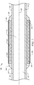
- the CSSP 200 generally comprises a mandrel 210, a sealing element 220 disposed circumferentially about/around at least a portion of the mandrel 210, and a jacket 230 covering at least a portion of the sealing element 220. Also, the CSSP 200 may be characterized with respect to a central or longitudinal axis 205.
- the mandrel 210 generally comprises a cylindrical or tubular structure or body.
- the mandrel 210 may be coaxially aligned with the central axis 205 of the CSSP 200.
- the mandrel 210 may comprise an unitary structure (e.g., a single unit of manufacture, such as a continuous length of pipe or tubing); alternatively, the mandrel 210 may comprise two or more operably connected components (e.g., two or more coupled subcomponents, such as by a threaded connection).
- a mandrel like mandrel 210 may comprise any suitable structure; such suitable structures will be appreciated by those of skill in the art upon viewing this disclosure.
- the tubular body of the mandrel 210 generally defines a continuous axial flowbore 211 that allows fluid movement through the mandrel 210.
- the mandrel 210 may be configured for incorporation into the wellbore tubular 120; alternatively, the mandrel 210 may be configured for incorporation into any suitable tubular string, such as for example a work string, a tool string, a segmented tubing string, a jointed pipe string, a coiled tubing string, a production tubing string, a drill string, the like, or combinations thereof.
- the mandrel 210 may comprise a suitable connection to the wellbore tubular 120 (e.g., to a casing string member, such as a casing joint). Suitable connections to a casing string will be known to those of skill in the art.
- the mandrel 210 is incorporated within the wellbore tubular 120 such that the axial flowbore 211 of the mandrel 210 is in fluid communication with the axial flowbore 121 of the wellbore tubular 120.
- the CSSP 200 may comprise one or more optional retaining element 240.
- an optional retaining element 240 may be disposed circumferentially about the mandrel 210 adjacent to and abutting the sealing element 220 on each side of the sealing element 220, as seen in the embodiment of Figure 2 .
- the optional retaining element 240 may be adjacent to and abutting the sealing element 220 on one side only, such as for example on a lower side of the sealing element 220, or on an upper side of the sealing element 220.
- the optional retaining element 240 may be secured onto the mandrel by any suitable retaining mechanism, such as for example screws, pins, shear pins, retaining bands, and the like, or combinations thereof.
- the optional retaining element 240 may comprise a plurality of elements, including but not limited to one or more spacer rings, one or more slips, one or more slip segments, one or more slip wedges, one or more extrusion limiters, and the like, or combinations thereof.
- the optional retaining element 240 may prevent or limit the longitudinal movement (e.g., along the central axis 205) of the sealing element 220 about the mandrel 210, while the sealing element 220 disposed circumferentially about the mandrel 210 is placed within the wellbore and/or subterranean formation.
- the optional retaining element 240 may prevent or limit the longitudinal expansion (e.g., along the central axis 205) of the sealing element 220, while allowing the radial expansion of the sealing element 220.
- the sealing element 220 may generally be configured to selectively seal and/or isolate two or more portions of an annular space surrounding the CSSP 200 (e.g., between the CSSP 200 and one or more walls of the wellbore 114), for example, by selectively providing a barrier extending circumferentially around at least a portion of the exterior of the CSSP 200.
- the sealing element 220 may generally comprise a hollow cylindrical structure having an interior bore (e.g., a tube-like and/or a ring-like structure).
- the sealing element 220 may comprise a suitable internal diameter, a suitable external diameter, and/or a suitable thickness, for example, as may be selected by one of skill in the art upon viewing this disclosure and in consideration of factors including, but not limited to, the size/diameter of the mandrel 210, the wall against which the sealing element is configured to engage, the force with which the sealing element is configured to engage such surface(s), or other related factors.
- the internal diameter of the sealing element 220 may be about the same as an external diameter of the mandrel 210.
- the sealing element 220 may be in sealing contact (e.g., a fluid-tight seal) with the mandrel 210.
- FIG. 2 illustrates a CSSP 200 comprising a single sealing element 220
- a similar CSSP may comprise two, three, four, five, or any other suitable number of sealing elements like sealing element 220.
- the sealing element 220 comprises a swellable material.
- a swellable material may be defined as any material (e.g., a polymer, such as for example an elastomer) that swells (e.g., exhibits an increase in mass and volume) upon contact with a selected fluid, i.e., a swelling agent.
- a selected fluid i.e., a swelling agent.
- the disclosure may refer to a polymer and/or a polymeric material. It is to be understood that the terms polymer and/or polymeric material herein are used interchangeably and are meant to each refer to compositions comprising at least one polymerized monomer in the presence or absence of other additives traditionally included in such materials.
- polymeric materials suitable for use as part of the swellable material include, but are not limited to homopolymers, random, block, graft, star- and hyper-branched polyesters, copolymers thereof, derivatives thereof, or combinations thereof.
- derivative herein is defined to include any compound that is made from one or more of the swellable materials, for example, by replacing one atom in the swellable material with another atom or group of atoms, rearranging two or more atoms in the swellable material, ionizing one of the swellable materials, or creating a salt of one of the swellable materials.
- copolymer as used herein is not limited to the combination of two polymers, but includes any combination of any number of polymers, e.g., graft polymers, terpolymers, and the like.
- the swellable material may be characterized as a resilient, volume changing material.
- the swellable material of the sealing element 220 may swell by from about 105 % to about 500 %, alternatively from about 115 % to about 400 %, or alternatively from about 125 % to about 200 %, based on the original volume at the surface, i.e., the volume of the swellable material of the sealing element 220 prior to contacting the sealing element 220 (e.g., swellable material) with the swelling agent.
- a swell gap of the sealing element 220 may increase by from about 105 % to about 250 %, alternatively from about 110 % to about 200 %, or alternatively from about 110 % to about 150 %, based on the swell gap of the sealing element 220 prior to contacting the sealing element 220 (e.g., swellable material) with the swelling agent.
- the swell gap is defined by an increase in a radius of the sealing element (e.g., swellable material) upon swelling divided by a thickness of the sealing element (e.g., swellable material) prior to swelling.
- the extent of swelling of a sealing element may depend upon a variety of factors, such as for example the downhole environmental conditions (e.g., temperature, pressure, composition of formation fluid in contact with the sealing element, specific gravity of the fluid, pH, salinity, etc.).
- the downhole environmental conditions e.g., temperature, pressure, composition of formation fluid in contact with the sealing element, specific gravity of the fluid, pH, salinity, etc.
- the swellable materials upon swelling to at least some extent (e.g., partial swelling, substantial swelling, full swelling), the swellable materials may be referred to as "swelled materials.”
- the sealing element 220 may be configured to exhibit a radial expansion (e.g., an increase in exterior diameter) upon being contacted with a swelling agent.
- the swelling agent may be a water-based fluid (e.g., aqueous solutions, water, etc.), an oil-based fluid (e.g., hydrocarbon fluid, oil fluid, oleaginous fluid, terpene fluid, diesel, gasoline, xylene, octane, hexane, etc.), or combinations thereof.
- a commercial nonlimiting example of an oil-based fluid includes EDC 95-11 drilling fluid.
- the swellable material may comprise a water-swellable material, an oil-swellable material, a water-and-oil-swellable material, or combinations thereof.
- the water-swellable materials may swell when contacted with a swelling agent comprising a water-based fluid
- the oil-swellable materials may swell when contacted with a swelling agent comprising an oil-based fluid
- the water-and-oil-swellable materials may swell when contacted with a swelling agent comprising a water-based fluid, an oil-based fluid, or both a water-based fluid and an oil-based fluid.
- a water-swellable material might exhibit some degree of oil-swellability (e.g., swelling when contacted with an oil-based fluid).
- an oil-swellable material might exhibit some degree of water-swellability (e.g., swelling when contacted with a water-based fluid).
- Nonlimititng examples of water-swellable materials suitable for use in the present disclosure include a tetrafluorethylene/propylene copolymer (TFE/P), a starch-polyacrylate acid graft copolymer, a polyvinyl alcohol/cyclic acid anhydride graft copolymer, an isobutylene/maleic anhydride copolymer, a vinyl acetate/acrylate copolymer, a polyethylene oxide polymer, graft-poly(ethylene oxide) of poly(acrylic acid), a carboxymethyl cellulose type polymer, a starch-polyacrylonitrile graft copolymer, polymethacrylate, polyacrylamide, an acrylamide/acrylic acid copolymer, poly(2-hydroxyethyl methacrylate), poly(2-hydroxypropyl methacrylate), a non-soluble acrylic polymer, a highly swelling clay mineral, sodium bentonite (e.g., sodium bentonite having as main ingredient mont
- Nonlimiting examples of oil-swellable materials suitable for use in the present disclosure include an oil-swellable rubber, a natural rubber, a polyurethane rubber, an acrylate/butadiene rubber, a butyl rubber (IIR), a brominated butyl rubber (BIIR), a chlorinated butyl rubber (CIIR), a chlorinated polyethylene rubber (CM/CPE), an isoprene rubber, a chloroprene rubber, a neoprene rubber, a butadiene rubber, a styrene/butadiene copolymer rubber (SBR), a sulphonated polyethylene (PES), chlor-sulphonated polyethylene (CSM), an ethylene/acrylate rubber (EAM, AEM), an epichlorohydrin/ethylene oxide copolymer rubber (CO, ECO), an ethylene/propylene copolymer rubber (EPM), ethylene/propylene/diene terpolymer (EPDM), a per
- Nonlimititng examples of water-and-oil-swellable materials suitable for use in the present disclosure include a nitrile rubber (NBR), an acrylonitrile/butadiene rubber, a hydrogenated nitrile rubber (HNBR), a highly saturated nitrile rubber (HNS), a hydrogenated acrylonitrile/butadiene rubber, an acrylic acid type polymer, poly(acrylic acid), polyacrylate rubber, a fluoro rubber (FKM), a perfluoro rubber (FFKM), and the like, derivatives thereof, or combinations thereof.
- NBR nitrile rubber
- HNBR hydrogenated nitrile rubber
- HNS highly saturated nitrile rubber
- FKM fluoro rubber
- FFKM perfluoro rubber
- a water-swellable material with a varying degree of low oil-swellability may be obtained by adding to an EPDM polymer or its precursor monomer mixture of (i) elastomer additive, such as for example nitrile, HNBR, fluoroelastomers, or acrylate-based elastomers, or their precursors; and (ii) an unsaturated organic acid, anhydride, or derivatives thereof (e.g., maleic acid, 2-acrylamido-2-methylpropane sulfonic acid), optionally combined with an inorganic expanding agent (e.g., sodium carbonate); wherein the unsaturated organic acid, anhydride, or derivatives thereof may be present within the EPDM polymer or its precursor monomer mixture in an amount of from about 1 to about 10 per hundred rubber (phr), and wherein the inorganic expanding agent may be present within the EPDM polymer or its precursor monomer mixture in an amount of from about 1 to about 10 phr.
- elastomer additive such as
- the unsaturated organic acid comprises a highly acidic unsaturated compound (e.g., 2-acrylamido-2-methylpropane sulfonic acid).
- a highly acidic unsaturated compound e.g., 2-acrylamido-2-methylpropane sulfonic acid
- the highly acidic unsaturated compound when added to the EPDM polymer or its precursor monomer mixture in an amount of from about 0.5 to about 5 phr, the resulting swellable material may have a variable oil-swellability, and may be further swellable in low pH fluids, such as for example completion fluids containing zinc bromide.
- a second addition of an additional amount of an inorganic expanding agent (e.g., an additional amount of from about 1 to about 10 phr) to the EPDM polymer or its precursor monomer mixture may enhance the swellability of the swellable material in low pH, high concentration brines.
- a zwitterionic polymer or copolymer of a zwitterionic monomer with an unsaturated monomer may be added to the EPDM polymer or its precursor monomer mixture to obtain a crosslinked swellable material.
- the amounts of the various ingredients used for producing or obtaining a polymeric swellable material may be varied as suited for the particular purpose at hand.
- the desired swellable material is a highly crosslinked, moderately water-swellable (e.g., about 150 % swell by volume) elastomer having very low oil-swellability, but very high swellability in low pH fluids
- the recipe might include, by way of example and not of limitation, from about 60 to about 80 phr of EPDM; from about 20 to about 40 phr of nitrile or HNBR; from about 4 to about 5 phr of 2-acrylamido-2-methylpropane sulfonic acid; and from about 15 to about 20 phr of a zwitterionic polymer or monomer.
- swellable materials that behave in a similar fashion with respect to oil-based fluids and/or water-based fluids may also be suitable.
- Those of ordinary skill in the art, with the benefit of this disclosure, will be able to select an appropriate swellable material for use in the compositions of the present invention based on a variety of factors, including the application in which the composition will be used and the desired swelling characteristics.
- Suitable swellable materials are commercially available as one or more components of SWELLPACKERS zonal isolation system from Halliburton Energy Services, Inc.
- the swellable materials suitable for use in this disclosure comprise swellable material particles of any suitable geometry, including without limitation beads, hollow beads, spheres, ovals, fibers, rods, pellets, platelets, disks, plates, ribbons, and the like, or combinations thereof.
- the swellable material may be characterized by a particle size of from about 0.1 microns to about 2000 microns, alternatively from about 0.5 microns to about 1500 microns, or alternatively from about 1 microns to about 1000 microns.
- Nonlimiting examples of swellable materials suitable for use in conjunction with the methods of this disclosure are described in more detail in U.S. Patent Nos. 3,385,367 ; 7,059,415 ; 7,143,832 ; 7,717,180 ; 7,934,554 ; 8,042,618 ; and 8,100,190 ; each of which is incorporated by reference herein in its entirety.
- the jacket 230 generally covers at least a portion of an outer surface 221 of the sealing element 220.
- the jacket 230 may be at least substantially impermeable to a swelling agent that is configured to cause the sealing element 220 to swell.
- the jacket 230 may be generally configured to control a swell-rate of the sealing element 220 (e.g., swell-rate of the swellable material), wherein the swellable material of the sealing element 220 may swell (e.g., expand or increase in volume) upon sufficient contact between the CSSP and the swelling agent.
- the swell-rate of a material is defined as the ratio between the volume expansion or increase of such material and the time or duration required for such volume expansion to occur; wherein the volume expansion represents the difference between a final volume assessed at the end of the evaluated time period and an initial volume assessed at the beginning of the evaluated time period.
- the swell-rate of the sealing element 220 and the swell-rate of the swellable material as part of the sealing element are about the same, although the swell-rate of the swellable material assessed outside of a CSSP (i.e., when the swellable material is not part of the CSSP) might be different than the swell-rate of the sealing element 220.
- the jacket 230 may control the swell-rate by limiting the exposure of the swellable material (e.g., the sealing element 220) to the swelling agent.
- contact between the swelling agent and the sealing element, and consequently the swelling of the swellable material may be dependent upon the geometry and composition of the jacket which controls fluidic access of the swelling agent to the sealing element as described in more detail herein.
- the jacket 230 may cover a suitable portion of the outer surface 221 of the sealing element 220, that is, a portion of the outer surface 221 of the sealing element 220 that would be exposed (e.g., so as to be in direct contact with a swelling agent, when such swelling agent is present), were the jacket 230 not present.
- the jacket 230 may cover equal to or greater than about 75 %, alternatively about 80 %, alternatively about 81 %, alternatively about 82 %, alternatively about 83 %, alternatively about 84 %, alternatively about 85 %, alternatively about 86 %, alternatively about 87 %, alternatively about 88 %, alternatively about 89 %, alternatively about 90 %, alternatively about 91 %, alternatively about 92 %, alternatively about 93 %, alternatively about 94 %, or alternatively about 95 % of the outer surface area of the sealing element 220.
- the jacket 230 provides at least a substantially fluid tight seal to the portion of the outer surface 221 of the sealing element 220 that it covers.
- teh jacket 230 may serve to prevent and/or limit direct contact between a fluid (e.g., a swelling agent) and the portion of the outer surface 221 of the sealing element 220 that is covered by the jacket 230.
- the substantially fluid tight seal provided by the jacket 230 may be provided when the jacket 230 comprises a diffusional flow rate of the swelling agent that is substantially less than the diffusional flow rate into the exposed portions of the sealing element 220.
- the ratio of the diffusional flow rate of the swelling agent through the jacket 230 to the diffusional flow rate into the exposed portions of the sealing element 220 may be at least about 1:10 to about 1:100.
- the jacket 230 may be impervious or impermeable with respect to the swelling agent.
- the jacket 230 may be substantially impervious or impermeable with respect to the swelling agent.
- the jacket 230 may have a low permeability with respect to the swelling agent.
- the jacket 230 may allow less than about 20 %, alternatively less than about 15 %, alternatively less than about 10 %, alternatively less than about 9 %, alternatively less than about 8 %, alternatively less than about 7 %, alternatively less than about 6 %, alternatively less than about 5 %, alternatively less than about 4 %, alternatively less than about 3 %, alternatively less than about 2 %, alternatively less than about 1 %, alternatively less than about 0.1 %, alternatively less than about 0.01 %, or alternatively less than about 0.001 % of the outer surface area 221 that is sealingly covered by the jacket 230 to be in direct contact with a swelling agent.
- the jacket 230 may comprise one or more coating layers.
- a coating layer of the jacket will be understood to be a coating layer of the jacket that was applied onto the sealing element 220 in a single coating or application procedure.
- a jacket 230 may comprise one coating layer of material A that has been applied in a single coating procedure.
- a jacket 230 may comprise two coating layers of material A, wherein material A has been applied onto to the sealing element 220 in two distinct coating procedures (e.g., each coating layer has been applied at a different time).
- a jacket 230 may comprise one coating layer of material A and one coating layer of material B, wherein the coating layer of material A and the coating layer of material B have each been applied onto to the sealing element 220 in two distinct coating procedures (each coating layer has been applied at a different time).
- a jacket 230 may comprise one coating layer of both material A and material B, wherein both material A and material B have been applied concomitantly (e.g., at the same time) onto to the sealing element 220.
- the jacket 230 may comprise at least two coating layers, alternatively at least three coating layers, alternatively at least four coating layers, or alternatively at least five or more coating layers.
- the first coating layer applied directly onto the sealing element 220 will be referred to as the "primer coating layer,” and any coating layer or layers applied subsequent to the primer coating layer will be referred to as a "top coating layer” or “top coating layers.”
- the top coating layer applied after the primer coating layer will be referred to as a "first top coating layer;” the top coating layer applied after the first top coating layer will be referred to as a "second top coating layer;” the top coating layer applied after the second top coating layer will be referred to as a "third top coating layer;” the top coating layer applied after the third top coating layer will be referred to as a "fourth top coating layer;” and so on.
- the first top coating layer will be closest to the sealing element out of any applied top coating layers
- the second top coating layer will be the second closest to the sealing element after the first top coating layer, and so on.
- the primer coating layer may function to activate the outer surface 221 of the sealing element 220, e.g., enable or promote adherence between the sealing element 220 and the top coating layer or layers.
- the primer coating is optional and may not be present in some embodiments.
- the primer coating layer may not be present when the coating material sufficiently adheres to the outer surface 221 of the sealing element 220.
- the primer coating layer may activate the outer surface 221 of the sealing element 220 by adhering to the sealing element, and then adhering to the top coating layer(s).
- the primer coating layer can be regarded as a "glue" between the sealing element 220 and the top coating layer(s) of the jacket.
- the primer coating layer may be useful when the top coating layer(s) of the jacket 230 would not adhere to the sealing element 220 such as to form a fluid tight seal, and the primer coating layer may be selected such as to form a fluid tight seal with both the sealing element 220 and the top coating layer(s).
- the primer coating layer comprises a water-based primer.
- the primer coating layer comprises an organic solvent-based primer.
- a nonlimiting example of a water-based primers suitable for use in the present disclosure includes a two component system, wherein a first component (e.g., base) comprises epoxy constituents and C 13 -C 15 alkyl glycidyl ether, and a second component (e.g., activator) comprises tetraethylenepentamine.
- a first component e.g., base
- a second component e.g., activator
- organic solvent-based primers suitable for use in the present disclosure include urethane, an isocyanate-based adhesive, and the like.
- the primer coating layer may be characterized by a thickness of less than about 10 microns, alternatively less than about 5 microns, or alternatively less than about 1 micron.
- the outer surface 221 of the sealing element 220 may be activated (e.g., to enable or promote adherence between the sealing element 220 and the top coating layer or layers) by flame treatments, plasma treatments, electron beam treatments, oxidation treatments, corona discharge treatments, hot air treatments, ozone treatments, ultraviolet light treatments, sand blast treatments, and the like, or any combination thereof.
- the top coating layer(s) may comprise a coating material that is impervious or impermeable with respect to the swelling agent. In an embodiment, the top coating layer(s) may comprise a coating material that is substantially impervious or impermeable with respect to the swelling agent. In an embodiment, the top coating layer(s) may comprise a coating material that has a low permeability with respect to the swelling agent.
- the top coating layer(s) may comprise a flexible coating material.
- a flexible coating material may be defined as a coating material that stretches as the sealing element swells or expands in volume, without losing sealing contact with the outer surface 221 of the sealing element 220.
- the flexible coating material may stretch at the same rate at which the outer surface of the sealing element 220 increases or expands.
- the ratio between the outer surface area of the sealing element 220 in sealing contact with the jacket and the surface area of the jacket 230 remains substantially the same throughout the swelling process, e.g., about 1:1, when the top coating layer comprises a flexible coating material.
- the top coating layer(s) may comprise a partially flexible coating material.
- the ratio between the outer surface area of the sealing element 220 in sealing contact with the jacket 230 and the surface area of the jacket 230 may vary during the swelling process, when the top coating layer comprises a partially flexible coating material.
- Nonlimiting examples of coating materials suitable for use with the jacket 230 may comprise plastics, polymeric materials, polyethylene, polypropylene, fluoro-elastomers, fluoropolymers, fluoropolymer elastomers, polytetrafluoroethylene, a tetrafluoroethylene/propylene copolymer (TFE/P), polyamide-imide (PAI), polyimide, polyphenylene sulfide (PPS), or combinations thereof.
- the coating material comprises a water-based coating material.
- the coating material comprises an organic solvent-based coating material.
- the coating material comprises a one-component system.
- the coating material comprises a multi-component system (e.g., a two-component system, a three-component system, etc.), wherein the multi-component system may undergo a crosslinking process during the drying/curing/hardening of the top layer(s).
- the top coating layer(s) may comprise a flexible binder system and a protective filler.
- a material that is a water-swellable material may be used as a top coating layer for an oil-swellable material that is designed to swell upon contact with a swelling agent comprising an oil-based fluid.
- a material that is an oil-swellable material may be used as a top coating layer for a water-swellable material that is designed to swell upon contact with a swelling agent comprising a water-based fluid.
- Nonlimiting examples of commercially available coating materials suitable to form the jacket 230 include ACCOLAN, ACCOAT, and ACCOFLEX, all of which are available from Accoat, located in Kvistgaard, Denmark; VITON which is a fluoropolymer elastomer available from DuPont; AFLAS which is a TFE/P available from Asahi Glass Co., LTD.; and VESPEL which is a polyimide available from DuPont.
- Other suitable coating materials may be appreciated by persons of skill in the art, and with the help of this disclosure.
- the top coating layer may be characterized by a thickness of from about 10 microns to about 100 microns, alternatively from about 30 microns to about 60 microns, or alternatively from about 35 microns to about 55 microns.
- some swellable materials might leach out (e.g., bleed, leak, come out, seep out, etc.) of the sealing element 220 over time.
- the swellable materials could leach out the sealing element 220 through the exposed outer surface (e.g., the portions of the outer surface not covered by the jacket 230). Consequently, over time, a CSSP like CSSP 220 might lose the ability to isolate two or more adjacent portions or zones within a subterranean formation (e.g., subterranean formation 102) and/or wellbore (e.g., wellbore 114).
- CSSP 200 may comprise an optional retention coating layer.
- the retention coating layer would prevent the outflow of swelling material from the sealing element 220 and would allow the inflow of the swelling agent, such that the swelling agent would contact the swellable material.
- the retention coating layer may cover about 100 %, alternatively about 99 %, alternatively about 98 %, alternatively about 97 %, or alternatively about 96 % of the outer surface area 221 of the sealing element 220 and/or the exposed surface area of the sealing element (e.g., the portion not covered by the jacket 230).
- the jacket when a retention coating layer is used, the jacket will be in sealing contact (e.g., a fluid tight seal) with the retention coating layer, and as such the inflow of swelling agent into the sealing element 220 may occur through the retention coating layer present on the exposed outer surface (e.g., the outer surface portions not in sealing contact with the jacket 230). Further, as will be appreciated by one of skill in the art, and with the help of this disclosure, the jacket 230 will prevent the outflow of swelling material from the sealing element 220 through the portions of the outer surface covered by the jacket 230.
- the retention coating layer comprises a flexible retention coating material.
- CSSP 200 may comprise an optional retention coating layer atop both the jacket 230 and the exposed portions of the outer surface (e.g., the portions of the outer surface not covered by the jacket 230).
- retention coating layer may be applied onto an outer surface of the CSSP 200(e.g., an outer surface of the sealing element 220) after the removal of a mask used to create the exposed portions of the outer surface (e.g., the portions of the outer surface not covered by the jacket 230), as will be described later herein.
- Other suitable configurations for the retention coating layer will be appreciated by one of skill in the art, and with the help of this disclosure.
- the retention coating material may comprise a water permeable or a water semi-permeable polymeric material, such as for example a sulfonated tetrafluoroethylene based fluoropolymer-copolymer, polyetheretherketone (PEEK), polyetherketone (PEK), and the like.
- a water permeable polymeric material such as for example a sulfonated tetrafluoroethylene based fluoropolymer-copolymer, polyetheretherketone (PEEK), polyetherketone (PEK), and the like.
- PEEK polyetheretherketone
- PEK polyetherketone
- the retention layer may be characterized by a thickness of from about 1 microns to about 100 microns, alternatively from about 5 microns to about 75 microns, or alternatively from about 10 microns to about 50 microns.
- the jacket 230 (e.g., the material comprising the jacket 230, such as for example the water-based primer, organic solvent-based primer, coating material, etc.) and/or the retention coating layer, or any layers thereof may be configured to be applied to the sealing element 220 by any suitable process.
- the jacket 230 and/or the retention coating layer, or any layers thereof may comprise a liquideous or substantially liquideous material that may be sprayed onto the sealing element 220, painted onto the sealing element 220, into which the sealing element 220 may be dipped, or the like.
- the material comprising the jacket 230 may be configured to dry (e.g., set, set up, set in place, cure, harden, crosslink, or the like) upon exposure to a predetermined condition or upon passage of a given duration of time.
- the jacket 230 and/or the retention coating layer, or any layers thereof may dry (or the like) upon being heated, cooled, exposed to a hardening chemical, or combinations thereof.
- the jacket 230 may be applied to only a portion of the outer surface of the sealing element 220, for example, thereby yielding an exposed outer surface portion (e.g., to which the jacket 230 material is not applied) and an unexposed outer surface portion (e.g., to which the jacket 230 material is applied).
- a perspective view of a CSSP 200 is illustrated.
- a portion of the sealing element 220 is exposed (e.g., an exposed portion 220a) and another portion is covered by the jacket 230 (e.g., an unexposed portion 220b).
- the relationship between the exposed and unexposed portions may comprise any suitable pattern, design, or the like.
- the exposed portion 220a may optionally comprise a retention coating layer, as previously described herein.
- the exposed and unexposed surfaces of the sealing element 220 may be obtained by "masking" or otherwise covering a portion of the outer surface 221 of the sealing element 220 (e.g., the portion of the outer surface 221 of the sealing element 220 which will be exposed) prior to application of the jacket 230 material.
- a “mask” may be configured to cover any suitable portion of the outer surface 221 of the sealing element 220.
- the mask may comprise a grid-like pattern, a diamond pattern, a pattern of vertical, horizontal, and/or helical strips, a random arrangement, etc.
- the pattern of the mask may also provide for any variety of opening shapes and sizes for a given surface area coverage.
- the mask may provide a few relatively large openings or a greater number of smaller openings.
- the openings or open areas can have any shape such as a round shape (circular, oval, elliptical, etc.), a square or rectangular shape, linear shape (e.g., vertical, horizontal, and/or helical stripes, etc.), or any other suitable shape.
- the mask may be made from any suitable material, examples of which include, but are not limited to, paper, plastic, wires, metals, various fibrous materials, thread, rope, net, or combinations thereof.
- CSSP 200 disclosed herein
- methods related to making/assembling and utilizing such a CSSP are also disclosed herein.
- a method of making a CSSP generally comprises the steps of providing a mandrel (e.g., mandrel 210 disclosed herein) having at least one sealing element (e.g., sealing element 220 disclosed herein) disposed about at least a portion thereof, masking at least a portion of the outer surface of the sealing element, applying a jacket (e.g., jacket 230 disclosed herein) to the sealing element in one or more layers, and removing the mask.
- a mandrel e.g., mandrel 210 disclosed herein
- at least one sealing element e.g., sealing element 220 disclosed herein
- a jacket e.g., jacket 230 disclosed herein
- the mandrel 210 having at least one sealing element 220 disposed about at least a portion thereof may be obtained.
- suitable mandrels 210 and sealing elements 220 may be obtained, alone or in combination, from Halliburton Energy Services, Inc.
- a portion of the sealing element 220 may be covered with a mask.
- a mask may be preformed in any suitable shape.
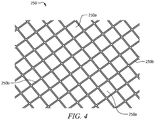
- An example of a suitable mask 250 is illustrated in Figure 4 , although one of skill in the art, upon viewing this disclosure, will appreciate other suitable configurations.
- the mask 250 comprises a grid-like pattern 250b having a plurality of void spaces 250a.
- a mask may be any suitable configuration.
- the mask may comprise a substantially uniform pattern; alternatively, the mask may have no pattern at all.
- the mask 250 may comprise a single sheet (e.g., as shown in Figure 4 ).
- the mask may comprise multiple sheets, ribbons, wires, or other suitable forms.
- the mask may be wrapped around (e.g., applied onto) the sealing element and secured in place prior to applying the jacket or any layers thereof.
- the jacket 230 or any layers thereof may be applied to the masked sealing element 220.
- the material comprising the jacket 230 e.g., water-based primer, organic solvent-based primer, coating material, etc.
- the material comprising the jacket 230 e.g., water-based primer, organic solvent-based primer, coating material, etc.
- the material comprising the jacket 230 e.g., water-based primer, organic solvent-based primer, coating material, etc.
- the masked sealing element 220 may be dipped, rolled, or submerged within the material comprising the jacket 230 (e.g., water-based primer, organic solvent-based primer, coating material, etc.) or any layers thereof.
- the material which will form the jacket 230 e.g., water-based primer, organic solvent-based primer, coating material, etc.
- the material of the jacket 230 e.g., water-based primer, organic solvent-based primer, coating material, etc.
- any layers thereof may adhere to the portions of the sealing element 220 not covered or shrouded by the mask 250.
- the material of the jacket 230 or any layers thereof may be allowed to dry (e.g., set, set up, set in place, cure, harden, crosslink, or the like) prior to removing the mask 250 and/or prior to applying another layer (e.g. a top coating layer).
- the mask 250 may be removed at any suitable time after the material of jacket 230 or any layers thereof has been applied thereto.
- a portion of the sealing element 220 a portion of the sealing element 220 is exposed (an exposed portion 220a) and another portion is covered by the jacket 230 (an unexposed portion 220b) or any layers thereof, as previously disclosed herein.
- a layer applied onto the masked sealing element 220 may be allowed to dry prior to the application of another layer; alternatively, subsequent layers may be applied onto a layer without allowing an already applied layer to dry.
- a method of utilizing a CSSP generally comprises the steps of providing a CSSP 200, disposing a tubular string having a CSSP 200 incorporated therein within a wellbore, and activating the CSSP 200. Additionally, in an embodiment, the method may further comprise performing a wellbore servicing operation, producing a reservoir fluid, or combinations thereof.
- providing a CSSP 200 may comprise one or more of the steps of the method of making the CSSP 200, as disclosed herein.
- the CSSP 200 may be utilized as disclosed herein.
- the CSSP 200 may be incorporated within a tubular string (e.g., a casing string like casing string 120, a work string, a tool string, a segmented tubing string, a jointed pipe string, a coiled tubing string, a production tubing string, a drill string, the like, or any other suitable wellbore tubular) and disposed within a wellbore (e.g., wellbore 114).
- a tubular string may comprise one, two, three, four, five, six, seven, eight, nine, ten, or more CSSPs incorporated therein.
- the CSSP(s) 200 may be incorporated into the tubular string as the tubular string is "run into” the wellbore (e.g., wellbore 114).
- the tubular strings are conventionally assembled in "joints" which are added to the uppermost end of the string (e.g., a tubular string) as the string is run in.
- the tubular string (e.g., casing string 120) may be assembled and run into the wellbore 114 until the CSSP(s) are located at a predetermined location, for example, such that a given CSSP (when expanded) will isolate (e.g., prevent fluid flow between) two adjacent zones of the subterranean formation 102 (e.g., formation zones 2, 4, 6, and 8) and/or portions of the wellbore 114.
- a when expanded, may isolate zones 2 and 4 from each other
- CSSP 200b when expanded, may isolate zones 4 and 6 from each other
- CSSP 200c when expanded, may isolate zones 6 and 8 from each other; etc.
- the tubular string e.g., casing string 120
- one or more CSSPs e.g., CSSP 200, CSSP 200a, CSSP 200b, CSSP 200c, CSSP 200d
- the CSSPs may be activated, i.e., caused to expand.
- activating the CSSP may comprise contacting the CSSP with the swelling agent.
- the swelling agent may comprise any suitable fluid, such as for example, a water-based fluid (e.g., aqueous solutions, water, etc.), an oil-based fluid (e.g., hydrocarbon fluid, oil fluid, oleaginous fluid, etc.), or combinations thereof.
- the swelling agent may comprise a fluid already present within the wellbore 114, for example, a servicing fluid, a formation fluid (e.g., a hydrocarbon fluid), or combinations thereof.
- the swelling agent may be introduced into the wellbore 114, e.g., as a servicing fluid.
- the swelling agent may be allowed to remain in contact with the CSSP (e.g., with the exposed portions 220a of the sealing element 220) for a sufficient amount of time for the sealing element to expand into contact with the subterranean formation (e.g., with the walls of the wellbore 114), for example, at least 2 days, alternatively at least 4 days, alternatively at least 8 days, alternatively at least 12 days, alternatively at least 2 weeks, alternatively at least 1 month, alternatively at least 2 months, alternatively at least 3 months, alternatively at least 4 months, or alternatively any suitable duration.
- contact with the swelling agent may cause the sealing element (e.g., sealing element 220) to expand into contact with the subterranean formation (e.g., with the walls of the wellbore 114).
- the expansion of the sealing element e.g., sealing element 220
- the expansion of the sealing element may be effective to isolate two or more portions of an annular space extending generally between the tubing string (e.g., casing string 120) and the walls of the wellbore (e.g., wellbore 114).
- the expansion of the sealing element (e.g., sealing element 220) may occur at a controlled rate (e.g., controlled swell-rate), as disclosed herein.
- the swelling agent might exhibit lateral/sideways diffusion of the swelling agent under the jacket (i.e., under the portions of the outer surface sealingly covered by the jacket), along with radial diffusion (e.g., diffusion of the swelling agent towards the mandrel 210).
- the expansion of the sealing element 220 may occur over a predetermined duration, for example, about 4 days, alternatively about 6 days, alternatively about 8 days, alternatively about 10 days, alternatively about 12 days, alternatively about 14 days, alternatively about 16 days, alternatively about 18 days, alternatively about 20 days, alternatively about 22 days, or alternatively about 24 days.
- the swell-rate of the sealing element may have a linear shape throughout the swelling process.
- the top layer coating may comprise a flexible coating material.
- a flexible coating material would stretch and stay in sealing contact with the sealing element, thus leading to an uniform swelling of the sealing element, i.e., an approximately linear swell-rate.
- the swell-rate of the sealing element may have an overall non-linear shape throughout the swelling process, e.g., a non-linear swell-rate.
- the top layer coating may comprise a partially flexible coating material.
- the swell-rate of the sealing element could have an initial linear portion corresponding to a first swell-rate characterized by an initial swelling period when the partially flexible coating material would stretch and stay in sealing contact with the sealing element.
- the linear swell-rate may then be followed by a rapid increase in the swell-rate (e.g., a linear increase in swell-rate with a steeper slope than the initial slope; an exponential increase in the swell-rate; etc.) corresponding to a second swell-rate owing to an inability of the partially flexible coating material to stretch further, causing the partially flexible coating material to separate (e.g., come off, peel off) from the sealing element either partially or completely.
- a rapid increase in the swell-rate e.g., a linear increase in swell-rate with a steeper slope than the initial slope; an exponential increase in the swell-rate; etc.
- a second swell-rate may be larger than the first swell-rate.
- the first swell-rate may last over a predetermined duration, for example, about 2 days, alternatively about 4 days, alternatively about 6 days, alternatively about 8 days, alternatively about 10 days, alternatively about 12 days, alternatively about 14 days, alternatively about 16 days, alternatively about 18 days, alternatively about 20 days, or alternatively about 22 days.
- the second swell-rate may last over a predetermined duration, for example, about 2 days, alternatively about 4 days, alternatively about 6 days, alternatively about 8 days, alternatively about 10 days, alternatively about 12 days, alternatively about 14 days, alternatively about 16 days, alternatively about 18 days, alternatively about 20 days, or alternatively about 22 days.
- a wellbore servicing operation may be performed with respect to one or more of such formation zones.
- the wellbore servicing operation may include any suitable servicing operation as will be appreciated by one of skill in the art upon viewing this disclosure. Examples of such wellbore servicing operations include, but are not limited to, a fracturing operation, a perforating operation, an acidizing operation, or combinations thereof.
- a formation fluid e.g., oil, gas, or both
- a formation fluid may be produced from the subterranean formation (e.g., subterranean formation 102) or one or more zones (e.g., zones 2, 4, 6 and/or 8) thereof.
- a wellbore servicing system and/or apparatus comprising a controlled swell-rate swellable packer such as a CSSP 200
- a wellbore servicing method employing such a wellbore servicing system and/or apparatus comprising a controlled swell-rate swellable packer (CSSP) such as a CSSP 200 may be advantageously employed in the performance of a wellbore servicing operation.
- CSSP controlled swell-rate swellable packer
- CSSP controlled swell-rate swellable packer
- the ability to control the swell-rate and consequently the swelling profile may improve the accuracy of placing and activating a controlled swell-rate swellable packer such as a CSSP 200, such that two or more portions of the wellbore and/or two or more zones of the subterranean formation are substantially isolated.
- a controlled swell-rate swellable packer such as a CSSP 200
- a jacket comprising a material that is substantially impermeable to a fluid configured to cause the sealing element to swell may allow for a variety of swelling patterns to be provided by the CSSP. For example, when the swell rate is controlled by the exposed surface area of the sealing element, the amount of the exposed area can be controlled during the CSSP manufacturing process. This may present an advantage relative to swellable packers utilizing a sealing element composition or semi-permeable layer thickness to control the swelling rate, where the composition and semi-permeable layer thickness can vary somewhat during the manufacturing process. Further, the use of a variety of patterns of the jacket can provide varying swelling characteristics (e.g., linear swelling rates, non-linear swelling rates, and various combinations thereof).
- the swell-rate of a CSSP may be advantageously controlled (e.g., modulated) by varying the type and/or composition of the swelling material; the type and/or composition of the jacket; the number of layers in the jacket; the pattern of the mask; the ratio between the portion of the outer surface of the sealing element exposed to the swelling agent and the portion of the outer surface of the sealing element cover by the jacket; the type and/or composition of the swelling agent; or combinations thereof.
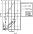
- the swelling properties of swellable materials coated with various types of coatings were investigated. More specifically, the swell curves for swellable materials were investigated both for coated and uncoated samples.
- the swellable material used was an oil-swellable rubber.
- the tested samples were either uncoated, or coated with ACCOLAN, ACCOAT or ACCOFLEX.
- the geometry of the tested samples was a hollow cylinder, wherein the outer diameter (OD) was 4.2 in, the inner diameter was 2.875 in, and the height was 0.1 m.
- the samples were coated with various patterns, such as a fine mesh, a coarse mesh, etc.
- the swelling agent used was EDC 95-11 drilling fluid.
- the following procedure was used for the testing of hollow cylinder materials comprised of an oil-swellable rubber.
- the tests were conducted at 110 °C.
- the hollow cylinder samples were placed at the bottom of an autoclavable test chamber, the chamber was filled with the swelling agent (e.g., EDC 95-11 drilling fluid), such that the sample(s) were fully covered, and then the autoclavable test chamber was heated at the desired temperature (e.g., 110 °C).
- the samples were positioned vertically in the autoclavable test chamber, such that the cylinder was "standing up.”
- the autoclavable test chamber was equipped with one or more sensors to sense and/or record the expansion of the hollow cylinder sample.
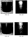
- FIGS. 6A and 6B display the same sample (e.g., a swellable material coated with a fine mesh jacket) in two different stages: prior to swelling, and fully swollen, respectively.
- Figures 6C and 6D display the same sample (e.g., a swellable material coated with a coarse mesh jacket) in two different stages: prior to swelling, and fully swollen, respectively.
- the swellable material used was an oil-swellable rubber, the jacket was an ACCOFLEX coating, the swelling agent was EDC 95-11 drilling fluid, and the pattern was a mesh as it can be seen from Figures 6A, 6B, 6C, and 6D .
- sample #1 The swelling properties of a swellable material were investigated. More specifically, the effect of the presence of a coating/jacket was visually monitored during swelling.
- Three similar samples (sample #1, sample #2 and sample #3) were studied as follows: sample #1 was fully coated; sample #2 was coated with a grid pattern, and sample #3 was uncoated. When used, the coating was ACCOFLEX. All three samples were made out of an oil-swellable rubber as the swellable material. The samples were submerged in EDC 95-11 drilling fluid as the swelling agent. The geometry of the samples before swelling was a cylinder. Figure 7 displays three samples upon exposure to the swelling agent.
- the uncoated swellable material (sample #3) exhibited the greatest expansion, while the fully coated swellable material (sample #1) exhibited the least expansion, and the partially coated swellable material (sample #2 coated with a grid-like pattern) exhibited an intermediate proportion of expansion.
- the swelling properties of swellable materials coated with various patterns of coatings or jackets were investigated. More specifically, the weight gain swell curves for swellable materials were investigated for various patterns.
- the swellable material used was an oil-swellable rubber.
- the geometry of the samples was a cylinder.
- the coating patterns were as follows: sample #4 was uncoated; sample #5 was fully coated; sample #6 was coated with few holes of uncoated areas; sample #7 was coated with many holes of uncoated areas; and sample #8 was coated with a mesh pattern of uncoated areas.
- the samples were submerged in EDC 95-11 drilling fluid as the swelling agent, and data points were recorded before exposure to the swelling agent, at 6 or 7 days of exposure, and then at 13 or 14 days of exposure to the swelling agent.
- the % weight gain was plotted against the time and the data are displayed in Figure 8 .
- the rates of expansion e.g., in terms of percent weight gain
- the swelling properties of a swellable material coated with a partially flexible coating were investigated. More specifically, the effect of the presence of a partially flexible coating was visually monitored during swelling.
- the swellable material used was an oil-swellable rubber, and the coating was ACCOAT, and the swelling agent was EDC 95-11 drilling fluid.
- the testing was conducted as described in Example 1.
- Figure 9 displays an image of the fully swollen coated swellable material, wherein the partially flexible coat was observed to be cracked and peeling off the surface of the swellable material.
- R 1 R 1 +k ⁇ (R u -R l ), wherein k is a variable ranging from 1 percent to 100 percent with a 1 percent increment, i.e., k is 1 percent, 2 percent, 3 percent, 4 percent, 5 percent, owing 50 percent, 51 percent, 52 percent, whereas, 95 percent, 96 percent, 97 percent, 98 percent, 99 percent, or 100 percent.
- any numerical range defined by two R numbers as defined in the above is also specifically disclosed.
- Use of the term "optionally" with respect to any element of a claim is intended to mean that the subject element is required, or alternatively, is not required. Both alternatives are intended to be within the scope of the claim.
Claims (19)
- Garniture d'étanchéité capable de gonfler à vitesse de gonflement régulée, comprenant :un mandrin (210) ;un élément d'étanchéité (220), dans laquelle l'élément d'étanchéité est disposé autour d'au moins une partie du mandrin ;un masque amovible sur au moins une partie d'une surface extérieure (221) de l'élément d'étanchéité, le masque amovible comprenant des espaces vides ; etune chemise (230) appliquée à l'élément d'étanchéité dont le masque amovible couvre la partie de la surface extérieure, et dans laquelle la chemise est conçue pour empêcher sensiblement la communication fluidique entre un fluide disposé à l'extérieur de la chemise et la partie de la surface extérieure de l'élément d'étanchéité couvert par la chemise, etdans laquelle le masque amovible est conçu de sorte que, lors du retrait, la chemise est appliquée uniquement sur une partie (220b) de la surface extérieure de l'élément d'étanchéité, ce qui donne une partie de surface extérieure exposée (220a).
- Garniture d'étanchéité capable de gonfler à vitesse de gonflement régulée selon la revendication 1, comprenant en outre une ou plusieurs butées d'extrémité (240) disposées autour du mandrin adjacent à l'élément d'étanchéité, dans laquelle les une ou plusieurs butées d'extrémité sont conçues pour maintenir l'élément d'étanchéité autour de la partie du mandrin.
- Garniture d'étanchéité capable de gonfler à vitesse de gonflement régulée selon les revendications 1 ou 2, dans laquelle l'élément d'étanchéité comprend un matériau gonflable.
- Garniture d'étanchéité capable de gonfler à vitesse de gonflement régulée selon la revendication 3, dans laquelle le matériau gonflable comprend au moins l'un :i) d'un matériau gonflable à l'eau, dans laquelle le matériau gonflable à l'eau comprend un copolymère de tétrafluoréthylène/propylène (TFE/P), un copolymère greffé d'amidon-acide polyacrylate, un copolymère greffé d'alcool polyvinylique/anhydride d'acide cyclique, un copolymère d'isobutylène/anhydride maléique, un copolymère d'acétate de vinyle/acrylate, un polymère d'oxyde de polyéthylène, un poly(oxyde d'éthylène) greffé de poly(acide acrylique), un polymère de type carboxyméthylcellulose, un copolymère greffé d'amidon-polyacrylonitrile, un polyméthacrylate, un polyacrylamide, un copolymère d'acrylamide/acide acrylique, un poly(2-hydroxyéthyl méthacrylate), un poly(2-hydroxypropyl méthacrylate), un polymère acrylique non soluble, un minéral argileux très gonflant, la bentonite de sodium, la bentonite de sodium ayant comme ingrédient principal la montmorillonite, la bentonite de calcium, leurs dérivés, ou des combinaisons de ceux-ci ;d'un matériau gonflable à l'huile, dans laquelle le matériau gonflable à l'huile comprend un caoutchouc gonflable à l'huile, un caoutchouc naturel, un caoutchouc polyuréthane, un caoutchouc acrylate/butadiène, un caoutchouc butyle (IIR), un caoutchouc butyle bromé (BUR), un caoutchouc butyle chloré (CIIR), un caoutchouc polyéthylène chloré (CM/CPE), un caoutchouc isoprène, un caoutchouc chloroprène, un caoutchouc néoprène, un caoutchouc butadiène, un caoutchouc copolymère styrène/butadiène (SBR), un polyéthylène sulfoné (PES), un polyéthylène chlorosulfoné (CSM), un caoutchouc éthylène/acrylate (EAM, AEM), un caoutchouc copolymère d'épichlorhydrine/oxyde d'éthylène (CO, ECO), un caoutchouc de copolymère d'éthylène/propylène (EPM), un terpolymère d'éthylène/propylène/diène (EPDM), un caoutchouc de copolymère d'éthylène/propylène réticulé au peroxyde, un caoutchouc de copolymère d'éthylène/propylène réticulé au soufre, un caoutchouc de terpolymère d'éthylène/propylène/diène (EPT), un copolymère d'éthylène/acétate de vinyle, un caoutchouc de fluoro silicone (FVMQ), un caoutchouc de silicone (VMQ), un poly 2,2,1-bicyclo heptène (polynorbomène), un polymère d'alkylstyrène, un copolymère de vinyle/acrylate substitué réticulé, des dérivés de ceux-ci, ou des combinaisons de ceux-ci, et ;
d'un matériau gonflable à l'eau et à l'huile, dans laquelle le matériau gonflable à l'eau et à l'huile comprend un caoutchouc nitrile (NBR), un caoutchouc acrylonitrile/butadiène, un caoutchouc nitrile hydrogéné (HNBR), un caoutchouc nitrile hautement saturé (HNS), un caoutchouc acrylonitrile/butadiène hydrogéné, un polymère de type acide acrylique, un poly(acide acrylique), un caoutchouc polyacrylate, un caoutchouc fluoré (FKM), un caoutchouc perfluoré (FFKM), leurs dérivés, ou des combinaisons de ceux-ci. - Garniture d'étanchéité capable de gonfler à vitesse de gonflement régulée selon une quelconque revendication précédente, dans laquelle la chemise comprend une couche de revêtement d'apprêt, éventuellement,
dans laquelle la couche de revêtement d'apprêt est caractérisée par une épaisseur inférieure à environ 10 microns. - Garniture d'étanchéité capable de gonfler à vitesse de gonflement régulée selon une quelconque revendication précédente, dans laquelle la chemise comprend au moins une couche de revêtement supérieure.
- Garniture d'étanchéité capable de gonfler à vitesse de gonflement régulée selon la revendication 6, dans laquelle la couche de revêtement supérieure comprend des matières plastiques, des matériaux polymères, du polyéthylène, du polypropylène, des fluoroélastomères, des fluoropolymères, des élastomères fluoropolymères, du polytétrafluoroéthylène, un copolymère de tétrafluoroéthylène/propylène (TFE/P), du polyamide-imide (PAI), du polyimide, du sulfure de polyphénylène (PPS), ou des combinaisons de ceux-ci, ou,
dans laquelle la couche de revêtement supérieure comprend un matériau de revêtement flexible ou un matériau de revêtement partiellement flexible, ou,
dans laquelle la couche de revêtement supérieure est caractérisée par une épaisseur allant d'environ 10 microns à environ 100 microns. - Garniture d'étanchéité capable de gonfler à vitesse de gonflement régulée selon une quelconque revendication précédente, comprenant en outre une couche de revêtement de rétention, éventuellement,
dans laquelle la couche de revêtement de rétention est caractérisée par une épaisseur allant d'environ 1 micron à environ 100 microns. - Procédé de fabrication d'une garniture d'étanchéité capable de gonfler à vitesse de gonflement régulée, comprenant :l'application d'un masque (250) sur au moins une partie d'une surface extérieure (221) d'un élément d'étanchéité (220), dans lequel l'élément d'étanchéité comprend un matériau gonflable et dans lequel le masque comprenddes espaces vides ;l'application d'une chemise (230) à l'élément d'étanchéité lorsque le masque est appliqué, dans lequel le masque empêche sensiblement l'application de la chemise sauf dans les espaces vides ;le retrait du masque après avoir appliqué la chemise ; etla fourniture d'une garniture d'étanchéité capable de gonfler à vitesse de gonflement régulée (200).
- Procédé selon la revendication 9, comprenant en outre l'application d'une couche de revêtement de rétention sur la surface extérieure de l'élément d'étanchéité,
dans lequel, éventuellement, la couche de revêtement de rétention est appliquée sur une surface extérieure de la garniture d'étanchéité capable de gonfler à vitesse de gonflement régulée après le retrait du masque. - Procédé utilisant une garniture d'étanchéité capable de gonfler à vitesse de gonflement régulée, comprenant :la disposition d'une colonne tubulaire (120) comprenant une garniture d'étanchéité capable de gonfler à vitesse de gonflement régulée (200) selon l'une quelconque des revendications 1 à 8 incorporée dans celle-ci à l'intérieur d'un puits de forage (114) dans une formation souterraine (102) ; etl'activation de la garniture d'étanchéité capable de gonfler à vitesse de gonflement régulée ;dans lequel la chemise est appliquée uniquement sur une partie (220a) de la surface extérieure de l'élément d'étanchéité, ce qui donne une partie de surface extérieure exposée (220a).
- Procédé selon la revendication 11, comprenant en outre le fait de permettre à la garniture d'étanchéité capable de gonfler à vitesse de gonflement régulée de gonfler dans une proportion comprise entre environ 105 % et environ 500 %, éventuellement, entre environ 125 % et environ 200 %, sur la base du volume du matériau gonflable de l'élément d'étanchéité avant d'activer la garniture d'étanchéité capable de gonfler à vitesse de gonflement régulée.
- Procédé selon les revendications 11 ou 12, dans lequel un espace de gonflement de l'élément d'étanchéité augmente dans une proportion comprise entre environ 105 % et environ 250 %, éventuellement, entre environ 110 % et environ 150 % sur la base de l'espace de gonflement de l'élément d'étanchéité avant l'activation de la garniture d'étanchéité capable de gonfler à vitesse de gonflement régulée.
- Procédé selon les revendications 11 ou 12, dans lequel la garniture d'étanchéité capable de gonfler à vitesse de gonflement régulée comprend en outre une couche de revêtement de rétention.
- Procédé selon les revendications 11 ou 12, dans lequel le procédé comprend en outre l'isolement d'au moins deux parties adjacentes du puits de forage à l'aide de la garniture d'étanchéité capable de gonfler à vitesse de gonflement régulée après l'activation de la garniture d'étanchéité capable de gonfler à vitesse de gonflement régulée.
- Procédé selon les revendications 11, 12, 13, 14 ou 15, dans lequel l'activation de la garniture d'étanchéité capable de gonfler à vitesse de gonflement régulée comprend la mise en contact d'au moins une partie de la garniture d'étanchéité à vitesse de gonflement régulée avec un agent gonflant, et le fait de permettre à l'élément d'étanchéité de gonfler.
- Procédé selon les revendications 11, 12, 13, 14, 15 ou 16, dans lequel l'élément d'étanchéité a une vitesse de gonflement linéaire.
- Procédé selon les revendications 11, 12, 13, 14, 15 ou 16, dans lequel l'élément d'étanchéité a une vitesse de gonflement non linéaire.
- Procédé selon l'une quelconque des revendications 11 à 18, comprenant en outre le contrôle d'une vitesse de gonflement de l'élément d'étanchéité en modifiant au moins l'un : d'un type et/ou d'une composition d'un matériau gonflant, d'un type et/ou d'une composition d'une chemise, d'un nombre de couches dans la chemise, d'un motif d'un masque, d'un rapport entre une partie d'une surface extérieure d'un élément d'étanchéité exposée à un agent gonflant et une partie de la surface extérieure de l'élément d'étanchéité couvert par la chemise, d'un type et/ou d'une composition de l'agent gonflant, ou de combinaisons de ceux-ci.
Applications Claiming Priority (2)
| Application Number | Priority Date | Filing Date | Title |
|---|---|---|---|
| US201261714653P | 2012-10-16 | 2012-10-16 | |
| PCT/US2013/063273 WO2014062391A1 (fr) | 2012-10-16 | 2013-10-03 | Garniture d'étanchéité capable de gonfler à vitesse de gonflement régulée et procédé associé |
Publications (3)
| Publication Number | Publication Date |
|---|---|
| EP2909433A1 EP2909433A1 (fr) | 2015-08-26 |
| EP2909433A4 EP2909433A4 (fr) | 2016-06-22 |
| EP2909433B1 true EP2909433B1 (fr) | 2020-03-11 |
Family
ID=50474346
Family Applications (1)
| Application Number | Title | Priority Date | Filing Date |
|---|---|---|---|
| EP13847947.2A Active EP2909433B1 (fr) | 2012-10-16 | 2013-10-03 | Garniture d'étanchéité capable de gonfler à vitesse de gonflement régulée et procédé associé |
Country Status (12)
| Country | Link |
|---|---|
| US (4) | US20140102726A1 (fr) |
| EP (1) | EP2909433B1 (fr) |
| CN (1) | CN104755698B (fr) |
| AU (1) | AU2013331694B2 (fr) |
| BR (1) | BR112015008405B1 (fr) |
| CA (2) | CA2888532C (fr) |
| DK (1) | DK2909433T3 (fr) |
| IN (1) | IN2015DN02454A (fr) |
| MX (1) | MX357806B (fr) |
| MY (1) | MY172691A (fr) |
| RU (1) | RU2623411C2 (fr) |
| WO (1) | WO2014062391A1 (fr) |
Families Citing this family (44)
| Publication number | Priority date | Publication date | Assignee | Title |
|---|---|---|---|---|
| US10738559B2 (en) * | 2014-06-13 | 2020-08-11 | Halliburton Energy Services, Inc. | Downhole tools comprising composite sealing elements |
| CN105987811B (zh) * | 2015-02-27 | 2019-07-09 | 中国石油化工股份有限公司 | 一种用于测试自膨胀式封隔器的装置 |
| WO2016176776A1 (fr) * | 2015-05-05 | 2016-11-10 | Risun Oilflow Solutions Inc. | Garniture de duse pouvant gonfler |
| MY185761A (en) * | 2016-02-02 | 2021-06-04 | Halliburton Energy Services Inc | Galvanic degradable downhole tools comprising doped aluminum alloys |
| CA3012595C (fr) | 2016-03-01 | 2021-10-19 | Halliburton Energy Services, Inc. | Procede pour retarder le gonflement d'une garniture d'etancheite par incorporation d'une enveloppe metallique soluble |
| US10060253B2 (en) | 2016-04-11 | 2018-08-28 | Baker Hughes Incorporated | Downhole systems and articles for determining a condition of a wellbore or downhole article, and related methods |
| US10364619B2 (en) * | 2016-05-20 | 2019-07-30 | Alaskan Energy Resources, Inc. | Integral electrically isolated centralizer and swell packer system |
| CN106050184B (zh) * | 2016-06-20 | 2018-11-16 | 天鼎联创密封技术(北京)有限公司 | 下端密封环包覆铜皮的胶筒、封隔器和桥塞 |
| CN105863553B (zh) * | 2016-06-20 | 2018-12-18 | 天鼎联创密封技术(北京)有限公司 | 下端密封环包覆有两片铜皮的胶筒、封隔器和桥塞 |
| CN105927183A (zh) * | 2016-07-06 | 2016-09-07 | 天鼎联创密封技术(北京)有限公司 | 下端密封环包覆上下两层铜皮的胶筒、封隔器和桥塞 |
| CN108286420A (zh) * | 2017-01-09 | 2018-07-17 | 中国石油化工股份有限公司 | 一种堵漏管串和油气井堵漏方法 |
| US11473391B2 (en) | 2017-02-07 | 2022-10-18 | Halliburton Energy Services, Inc. | Packer sealing element with non-swelling layer |
| US10738560B2 (en) | 2017-04-25 | 2020-08-11 | Baker Hughes, A Ge Company, Llc | Packers having controlled swelling and methods of manufacturing thereof |
| CN107420065B (zh) * | 2017-05-08 | 2023-08-11 | 西安石油大学 | 一种智能弹性胶筒及其制备方法 |
| US10822909B2 (en) | 2017-08-17 | 2020-11-03 | Baker Hughes, A Ge Company, Llc | Packers having controlled swelling |
| US10961427B2 (en) * | 2017-09-22 | 2021-03-30 | Baker Hughes, A Ge Company, Llc | Completion tools with fluid diffusion control layer |
| RU2661935C1 (ru) * | 2017-09-26 | 2018-07-23 | Федеральное государственное бюджетное образовательное учреждение высшего образования "Тюменский индустриальный университет" (ТИУ) | Способ проведения водоизоляционных работ в добывающей скважине, вскрывшей водонефтяную залежь |
| BR112020005388B1 (pt) * | 2017-11-13 | 2023-03-21 | Halliburton Energy Services, Inc | Método para formar uma vedação em um furo de poço e pilha de vedação de metal intumescível |
| SG11202006956VA (en) | 2018-02-23 | 2020-08-28 | Halliburton Energy Services Inc | Swellable metal for swell packer |
| CN108892793B (zh) * | 2018-05-04 | 2021-01-12 | 浙江杭化新材料科技有限公司 | 一种绿色可降解高阻隔高透明度纳米纤维素复合膜的制备方法 |
| RU2690929C1 (ru) * | 2018-10-09 | 2019-06-06 | Общество с ограниченной ответственностью "ИНЖИНИРИНГОВЫЙ ЦЕНТР "ПОЛИМЕРНЫЕ МАТЕРИАЛЫ И ТЕХНОЛОГИИ" (ООО "ИЦ "ПМИТ") | Водонефтенабухающая термопластичная эластомерная композиция |
| WO2020171825A1 (fr) | 2019-02-22 | 2020-08-27 | Halliburton Energy Services, Inc. | Matériau d'étanchéité métallique expansible destiné à être utilisé avec des systèmes de complétion multilatéraux |
| RU191414U1 (ru) * | 2019-03-06 | 2019-08-05 | Публичное акционерное общество «Татнефть» имени В.Д. Шашина | Пакер набухающий |
| NO20211063A1 (en) | 2019-04-05 | 2021-09-03 | Univ Texas | Delay coating for wellbore isolation device |
| US10961812B2 (en) | 2019-04-05 | 2021-03-30 | Baker Hughes Oilfield Operations Llc | Disintegratable bismaleimide composites for downhole tool applications |
| NO20211090A1 (en) * | 2019-04-10 | 2021-09-09 | Halliburton Energy Services Inc | Protective barrier coating to improve bond integrity in downhole exposures |
| BR112021024386A2 (pt) | 2019-07-31 | 2022-02-08 | Halliburton Energy Services Inc | Método para monitorar a expansão de um vedante metálico de fundo de poço e sistema de medição do vedante metálico de fundo de poço |
| US10961804B1 (en) | 2019-10-16 | 2021-03-30 | Halliburton Energy Services, Inc. | Washout prevention element for expandable metal sealing elements |
| US11519239B2 (en) | 2019-10-29 | 2022-12-06 | Halliburton Energy Services, Inc. | Running lines through expandable metal sealing elements |
| WO2021118521A1 (fr) * | 2019-12-09 | 2021-06-17 | Thru Tubing Solutions, Inc. | Dispositifs de bouchage comportant des filaments revêtus d'un matériau gonflable |
| US11946332B2 (en) | 2019-12-17 | 2024-04-02 | Halliburton Energy Services, Inc. | Metallic delay barrier coating for swellable packers |
| US11761290B2 (en) | 2019-12-18 | 2023-09-19 | Halliburton Energy Services, Inc. | Reactive metal sealing elements for a liner hanger |
| US11499399B2 (en) | 2019-12-18 | 2022-11-15 | Halliburton Energy Services, Inc. | Pressure reducing metal elements for liner hangers |
| KR102160087B1 (ko) * | 2020-05-28 | 2020-09-28 | (주)인텔리지오 | 현장 압축 롤러를 이용한 팩커 설치 방법 및 이에 사용되는 압축 롤러 |
| RU2744341C1 (ru) * | 2020-08-18 | 2021-03-05 | Федеральное государственное бюджетное образовательное учреждение высшего образования "Волгоградский государственный технический университет" (ВолгГТУ) | Водонефтенабухающая эластомерная композиция |
| US11761293B2 (en) | 2020-12-14 | 2023-09-19 | Halliburton Energy Services, Inc. | Swellable packer assemblies, downhole packer systems, and methods to seal a wellbore |
| US11572749B2 (en) | 2020-12-16 | 2023-02-07 | Halliburton Energy Services, Inc. | Non-expanding liner hanger |
| RU2751316C1 (ru) * | 2020-12-29 | 2021-07-13 | Общество с ограниченной ответственностью "НАБЕРЕЖНОЧЕЛНИНСКИЙ ТРУБНЫЙ ЗАВОД" | Резиновая смесь |
| US11578498B2 (en) | 2021-04-12 | 2023-02-14 | Halliburton Energy Services, Inc. | Expandable metal for anchoring posts |
| US11879304B2 (en) | 2021-05-17 | 2024-01-23 | Halliburton Energy Services, Inc. | Reactive metal for cement assurance |
| RU2767071C1 (ru) * | 2021-06-09 | 2022-03-16 | Общество с ограниченной ответственностью "НАБЕРЕЖНОЧЕЛНИНСКИЙ ТРУБНЫЙ ЗАВОД" | Резиновая смесь для изготовления водонабухающих изделий |
| RU2765950C1 (ru) * | 2021-06-09 | 2022-02-07 | Общество с ограниченной ответственностью "НАБЕРЕЖНОЧЕЛНИНСКИЙ ТРУБНЫЙ ЗАВОД" | Резиновая смесь для изготовления нефтенабухающих изделий |
| US20230069138A1 (en) * | 2021-08-31 | 2023-03-02 | Halliburton Energy Services, Inc. | Controlled actuation of a reactive metal |
| WO2024010611A1 (fr) * | 2022-07-08 | 2024-01-11 | Halliburton Energy Services, Inc. | Massif de gravier poreux à auto-assemblage dans un puits de forage |
Family Cites Families (23)
| Publication number | Priority date | Publication date | Assignee | Title |
|---|---|---|---|---|
| US3385367A (en) | 1966-12-07 | 1968-05-28 | Kollsman Paul | Sealing device for perforated well casing |
| GB2197363B (en) * | 1986-11-14 | 1990-09-12 | Univ Waterloo | Packing seal for boreholes |
| GB9324436D0 (en) * | 1993-11-27 | 1994-01-12 | Ryford Ltd | Tape dispenser |
| NO312478B1 (no) | 2000-09-08 | 2002-05-13 | Freyer Rune | Fremgangsmåte for å tette ringrom ved oljeproduksjon |
| MY135121A (en) * | 2001-07-18 | 2008-02-29 | Shell Int Research | Wellbore system with annular seal member |
| RU2309239C2 (ru) * | 2005-08-08 | 2007-10-27 | Валентин Павлович Рылов | Устьевой сальник |
| US7717180B2 (en) | 2006-06-29 | 2010-05-18 | Halliburton Energy Services, Inc. | Swellable elastomers and associated methods |
| US7562704B2 (en) * | 2006-07-14 | 2009-07-21 | Baker Hughes Incorporated | Delaying swelling in a downhole packer element |
| DE602007007726D1 (de) * | 2007-04-06 | 2010-08-26 | Schlumberger Services Petrol | Verfahren und Zusammensetzung zur Zonenisolierung eines Bohrlochs |
| US7938191B2 (en) * | 2007-05-11 | 2011-05-10 | Schlumberger Technology Corporation | Method and apparatus for controlling elastomer swelling in downhole applications |
| CA2690340C (fr) * | 2007-06-21 | 2015-10-20 | Swelltec Limited | Appareil et procede faisant intervenir un corps se dilatant au contact d'eau et un corps se dilatant au contact d'hydrocarbures |
| US20090139710A1 (en) * | 2007-11-30 | 2009-06-04 | Schlumberger Technology Corporation | Swellable compositions and methods and devices for controlling them |
| US20090178800A1 (en) | 2008-01-14 | 2009-07-16 | Korte James R | Multi-Layer Water Swelling Packer |
| US20090205841A1 (en) * | 2008-02-15 | 2009-08-20 | Jurgen Kluge | Downwell system with activatable swellable packer |
| US7681653B2 (en) * | 2008-08-04 | 2010-03-23 | Baker Hughes Incorporated | Swelling delay cover for a packer |
| US8225880B2 (en) * | 2008-12-02 | 2012-07-24 | Schlumberger Technology Corporation | Method and system for zonal isolation |
| US7934554B2 (en) | 2009-02-03 | 2011-05-03 | Halliburton Energy Services, Inc. | Methods and compositions comprising a dual oil/water-swellable particle |
| CN201460803U (zh) * | 2009-08-07 | 2010-05-12 | 中国石油天然气股份有限公司 | 遇油、遇水自膨胀封隔器 |
| US8042618B2 (en) | 2009-08-11 | 2011-10-25 | Halliburton Energy Services, Inc. | Methods for swelling swellable elements in a portion of a well using an oil-in-water emulsion |
| US8100190B2 (en) | 2009-08-11 | 2012-01-24 | Halliburton Energy Services, Inc. | Methods for swelling swellable elements in a portion of a well using a water-in-oil emulsion |
| US20110120733A1 (en) * | 2009-11-20 | 2011-05-26 | Schlumberger Technology Corporation | Functionally graded swellable packers |
| US8459366B2 (en) * | 2011-03-08 | 2013-06-11 | Halliburton Energy Services, Inc. | Temperature dependent swelling of a swellable material |
| RU108095U1 (ru) * | 2011-05-26 | 2011-09-10 | Алексей Викторович Власов | Пакер |
-
2013
- 2013-09-30 US US14/041,413 patent/US20140102726A1/en not_active Abandoned
- 2013-10-03 CA CA2888532A patent/CA2888532C/fr active Active
- 2013-10-03 AU AU2013331694A patent/AU2013331694B2/en active Active
- 2013-10-03 DK DK13847947.2T patent/DK2909433T3/da active
- 2013-10-03 MX MX2015004748A patent/MX357806B/es active IP Right Grant
- 2013-10-03 RU RU2015112674A patent/RU2623411C2/ru active
- 2013-10-03 CA CA2988943A patent/CA2988943C/fr active Active
- 2013-10-03 IN IN2454DEN2015 patent/IN2015DN02454A/en unknown
- 2013-10-03 CN CN201380053827.2A patent/CN104755698B/zh active Active
- 2013-10-03 EP EP13847947.2A patent/EP2909433B1/fr active Active
- 2013-10-03 WO PCT/US2013/063273 patent/WO2014062391A1/fr active Application Filing
- 2013-10-03 MY MYPI2015000739A patent/MY172691A/en unknown
- 2013-10-03 BR BR112015008405-2A patent/BR112015008405B1/pt active IP Right Grant
- 2013-11-20 US US14/085,447 patent/US9869152B2/en active Active
-
2017
- 2017-12-08 US US15/835,782 patent/US10012051B2/en active Active
-
2018
- 2018-06-05 US US16/000,461 patent/US10443340B2/en active Active
Non-Patent Citations (1)
| Title |
|---|
| None * |
Also Published As
| Publication number | Publication date |
|---|---|
| US20140102728A1 (en) | 2014-04-17 |
| US9869152B2 (en) | 2018-01-16 |
| RU2015112674A (ru) | 2016-12-10 |
| MY172691A (en) | 2019-12-10 |
| WO2014062391A1 (fr) | 2014-04-24 |
| MX357806B (es) | 2018-07-25 |
| US20140102726A1 (en) | 2014-04-17 |
| US10012051B2 (en) | 2018-07-03 |
| US20180291701A1 (en) | 2018-10-11 |
| CA2888532C (fr) | 2018-01-30 |
| CA2988943A1 (fr) | 2014-04-24 |
| BR112015008405B1 (pt) | 2021-03-16 |
| CN104755698B (zh) | 2017-11-21 |
| CN104755698A (zh) | 2015-07-01 |
| AU2013331694B2 (en) | 2016-11-10 |
| CA2888532A1 (fr) | 2014-04-24 |
| US10443340B2 (en) | 2019-10-15 |
| DK2909433T3 (en) | 2020-03-30 |
| IN2015DN02454A (fr) | 2015-09-04 |
| RU2623411C2 (ru) | 2017-06-26 |
| EP2909433A4 (fr) | 2016-06-22 |
| MX2015004748A (es) | 2015-10-12 |
| CA2988943C (fr) | 2019-06-04 |
| EP2909433A1 (fr) | 2015-08-26 |
| AU2013331694A1 (en) | 2015-04-09 |
| US20180100371A1 (en) | 2018-04-12 |
| BR112015008405A2 (pt) | 2017-07-04 |
Similar Documents
| Publication | Publication Date | Title |
|---|---|---|
| US10443340B2 (en) | Method for making controlled swell-rate swellable packer | |
| NL1042686B1 (en) | Packer sealing element with non-swelling layer | |
| GB2514195B (en) | Oilfield apparatus and method comprising swellable elastomers | |
| US11448033B2 (en) | Delay coating for wellbore isolation device | |
| US20080277109A1 (en) | Method and apparatus for controlling elastomer swelling in downhole applications | |
| CA2922794A1 (fr) | Balles d'obturation gonflables | |
| US20130284436A1 (en) | Method of providing an annular seal, and wellbore system | |
| US20130092401A1 (en) | Method and Flexible Bodies for Subterrain Sealing |
Legal Events
| Date | Code | Title | Description |
|---|---|---|---|
| PUAI | Public reference made under article 153(3) epc to a published international application that has entered the european phase |
Free format text: ORIGINAL CODE: 0009012 |
|
| 17P | Request for examination filed |
Effective date: 20150410 |
|
| AK | Designated contracting states |
Kind code of ref document: A1 Designated state(s): AL AT BE BG CH CY CZ DE DK EE ES FI FR GB GR HR HU IE IS IT LI LT LU LV MC MK MT NL NO PL PT RO RS SE SI SK SM TR |
|
| AX | Request for extension of the european patent |
Extension state: BA ME |
|
| DAX | Request for extension of the european patent (deleted) | ||
| REG | Reference to a national code |
Ref country code: DE Ref legal event code: R079 Ref document number: 602013066794 Country of ref document: DE Free format text: PREVIOUS MAIN CLASS: E21B0043080000 Ipc: E21B0033120000 |
|
| RA4 | Supplementary search report drawn up and despatched (corrected) |
Effective date: 20160525 |
|
| RIC1 | Information provided on ipc code assigned before grant |
Ipc: E21B 33/12 20060101AFI20160519BHEP |
|
| STAA | Information on the status of an ep patent application or granted ep patent |
Free format text: STATUS: EXAMINATION IS IN PROGRESS |
|
| 17Q | First examination report despatched |
Effective date: 20180806 |
|
| GRAP | Despatch of communication of intention to grant a patent |
Free format text: ORIGINAL CODE: EPIDOSNIGR1 |
|
| STAA | Information on the status of an ep patent application or granted ep patent |
Free format text: STATUS: GRANT OF PATENT IS INTENDED |
|
| INTG | Intention to grant announced |
Effective date: 20191104 |
|
| GRAS | Grant fee paid |
Free format text: ORIGINAL CODE: EPIDOSNIGR3 |
|
| GRAA | (expected) grant |
Free format text: ORIGINAL CODE: 0009210 |
|
| STAA | Information on the status of an ep patent application or granted ep patent |
Free format text: STATUS: THE PATENT HAS BEEN GRANTED |
|
| AK | Designated contracting states |
Kind code of ref document: B1 Designated state(s): AL AT BE BG CH CY CZ DE DK EE ES FI FR GB GR HR HU IE IS IT LI LT LU LV MC MK MT NL NO PL PT RO RS SE SI SK SM TR |
|
| REG | Reference to a national code |
Ref country code: GB Ref legal event code: FG4D |
|
| REG | Reference to a national code |
Ref country code: CH Ref legal event code: EP |
|
| REG | Reference to a national code |
Ref country code: AT Ref legal event code: REF Ref document number: 1243352 Country of ref document: AT Kind code of ref document: T Effective date: 20200315 |
|
| REG | Reference to a national code |
Ref country code: DE Ref legal event code: R096 Ref document number: 602013066794 Country of ref document: DE |
|
| REG | Reference to a national code |
Ref country code: DK Ref legal event code: T3 Effective date: 20200327 Ref country code: RO Ref legal event code: EPE |
|
| REG | Reference to a national code |
Ref country code: IE Ref legal event code: FG4D |
|
| REG | Reference to a national code |
Ref country code: NO Ref legal event code: T2 Effective date: 20200311 |
|
| REG | Reference to a national code |
Ref country code: NL Ref legal event code: FP |
|
| PG25 | Lapsed in a contracting state [announced via postgrant information from national office to epo] |
Ref country code: RS Free format text: LAPSE BECAUSE OF FAILURE TO SUBMIT A TRANSLATION OF THE DESCRIPTION OR TO PAY THE FEE WITHIN THE PRESCRIBED TIME-LIMIT Effective date: 20200311 Ref country code: FI Free format text: LAPSE BECAUSE OF FAILURE TO SUBMIT A TRANSLATION OF THE DESCRIPTION OR TO PAY THE FEE WITHIN THE PRESCRIBED TIME-LIMIT Effective date: 20200311 |
|
| PG25 | Lapsed in a contracting state [announced via postgrant information from national office to epo] |
Ref country code: HR Free format text: LAPSE BECAUSE OF FAILURE TO SUBMIT A TRANSLATION OF THE DESCRIPTION OR TO PAY THE FEE WITHIN THE PRESCRIBED TIME-LIMIT Effective date: 20200311 Ref country code: BG Free format text: LAPSE BECAUSE OF FAILURE TO SUBMIT A TRANSLATION OF THE DESCRIPTION OR TO PAY THE FEE WITHIN THE PRESCRIBED TIME-LIMIT Effective date: 20200611 Ref country code: GR Free format text: LAPSE BECAUSE OF FAILURE TO SUBMIT A TRANSLATION OF THE DESCRIPTION OR TO PAY THE FEE WITHIN THE PRESCRIBED TIME-LIMIT Effective date: 20200612 Ref country code: SE Free format text: LAPSE BECAUSE OF FAILURE TO SUBMIT A TRANSLATION OF THE DESCRIPTION OR TO PAY THE FEE WITHIN THE PRESCRIBED TIME-LIMIT Effective date: 20200311 Ref country code: LV Free format text: LAPSE BECAUSE OF FAILURE TO SUBMIT A TRANSLATION OF THE DESCRIPTION OR TO PAY THE FEE WITHIN THE PRESCRIBED TIME-LIMIT Effective date: 20200311 |
|
| REG | Reference to a national code |
Ref country code: LT Ref legal event code: MG4D |
|
| PG25 | Lapsed in a contracting state [announced via postgrant information from national office to epo] |
Ref country code: IS Free format text: LAPSE BECAUSE OF FAILURE TO SUBMIT A TRANSLATION OF THE DESCRIPTION OR TO PAY THE FEE WITHIN THE PRESCRIBED TIME-LIMIT Effective date: 20200711 Ref country code: PT Free format text: LAPSE BECAUSE OF FAILURE TO SUBMIT A TRANSLATION OF THE DESCRIPTION OR TO PAY THE FEE WITHIN THE PRESCRIBED TIME-LIMIT Effective date: 20200805 Ref country code: SK Free format text: LAPSE BECAUSE OF FAILURE TO SUBMIT A TRANSLATION OF THE DESCRIPTION OR TO PAY THE FEE WITHIN THE PRESCRIBED TIME-LIMIT Effective date: 20200311 Ref country code: CZ Free format text: LAPSE BECAUSE OF FAILURE TO SUBMIT A TRANSLATION OF THE DESCRIPTION OR TO PAY THE FEE WITHIN THE PRESCRIBED TIME-LIMIT Effective date: 20200311 Ref country code: SM Free format text: LAPSE BECAUSE OF FAILURE TO SUBMIT A TRANSLATION OF THE DESCRIPTION OR TO PAY THE FEE WITHIN THE PRESCRIBED TIME-LIMIT Effective date: 20200311 Ref country code: EE Free format text: LAPSE BECAUSE OF FAILURE TO SUBMIT A TRANSLATION OF THE DESCRIPTION OR TO PAY THE FEE WITHIN THE PRESCRIBED TIME-LIMIT Effective date: 20200311 Ref country code: LT Free format text: LAPSE BECAUSE OF FAILURE TO SUBMIT A TRANSLATION OF THE DESCRIPTION OR TO PAY THE FEE WITHIN THE PRESCRIBED TIME-LIMIT Effective date: 20200311 |
|
| REG | Reference to a national code |
Ref country code: AT Ref legal event code: MK05 Ref document number: 1243352 Country of ref document: AT Kind code of ref document: T Effective date: 20200311 |
|
| REG | Reference to a national code |
Ref country code: DE Ref legal event code: R097 Ref document number: 602013066794 Country of ref document: DE |
|
| PLBE | No opposition filed within time limit |
Free format text: ORIGINAL CODE: 0009261 |
|
| STAA | Information on the status of an ep patent application or granted ep patent |
Free format text: STATUS: NO OPPOSITION FILED WITHIN TIME LIMIT |
|
| PG25 | Lapsed in a contracting state [announced via postgrant information from national office to epo] |
Ref country code: ES Free format text: LAPSE BECAUSE OF FAILURE TO SUBMIT A TRANSLATION OF THE DESCRIPTION OR TO PAY THE FEE WITHIN THE PRESCRIBED TIME-LIMIT Effective date: 20200311 Ref country code: AT Free format text: LAPSE BECAUSE OF FAILURE TO SUBMIT A TRANSLATION OF THE DESCRIPTION OR TO PAY THE FEE WITHIN THE PRESCRIBED TIME-LIMIT Effective date: 20200311 Ref country code: IT Free format text: LAPSE BECAUSE OF FAILURE TO SUBMIT A TRANSLATION OF THE DESCRIPTION OR TO PAY THE FEE WITHIN THE PRESCRIBED TIME-LIMIT Effective date: 20200311 |
|
| 26N | No opposition filed |
Effective date: 20201214 |
|
| PG25 | Lapsed in a contracting state [announced via postgrant information from national office to epo] |
Ref country code: PL Free format text: LAPSE BECAUSE OF FAILURE TO SUBMIT A TRANSLATION OF THE DESCRIPTION OR TO PAY THE FEE WITHIN THE PRESCRIBED TIME-LIMIT Effective date: 20200311 Ref country code: SI Free format text: LAPSE BECAUSE OF FAILURE TO SUBMIT A TRANSLATION OF THE DESCRIPTION OR TO PAY THE FEE WITHIN THE PRESCRIBED TIME-LIMIT Effective date: 20200311 |
|
| REG | Reference to a national code |
Ref country code: CH Ref legal event code: PL |
|
| PG25 | Lapsed in a contracting state [announced via postgrant information from national office to epo] |
Ref country code: LU Free format text: LAPSE BECAUSE OF NON-PAYMENT OF DUE FEES Effective date: 20201003 Ref country code: MC Free format text: LAPSE BECAUSE OF FAILURE TO SUBMIT A TRANSLATION OF THE DESCRIPTION OR TO PAY THE FEE WITHIN THE PRESCRIBED TIME-LIMIT Effective date: 20200311 |
|
| REG | Reference to a national code |
Ref country code: BE Ref legal event code: MM Effective date: 20201031 |
|
| PG25 | Lapsed in a contracting state [announced via postgrant information from national office to epo] |
Ref country code: FR Free format text: LAPSE BECAUSE OF NON-PAYMENT OF DUE FEES Effective date: 20201031 |
|
| PG25 | Lapsed in a contracting state [announced via postgrant information from national office to epo] |
Ref country code: BE Free format text: LAPSE BECAUSE OF NON-PAYMENT OF DUE FEES Effective date: 20201031 Ref country code: CH Free format text: LAPSE BECAUSE OF NON-PAYMENT OF DUE FEES Effective date: 20201031 Ref country code: LI Free format text: LAPSE BECAUSE OF NON-PAYMENT OF DUE FEES Effective date: 20201031 |
|
| PG25 | Lapsed in a contracting state [announced via postgrant information from national office to epo] |
Ref country code: IE Free format text: LAPSE BECAUSE OF NON-PAYMENT OF DUE FEES Effective date: 20201003 |
|
| PG25 | Lapsed in a contracting state [announced via postgrant information from national office to epo] |
Ref country code: TR Free format text: LAPSE BECAUSE OF FAILURE TO SUBMIT A TRANSLATION OF THE DESCRIPTION OR TO PAY THE FEE WITHIN THE PRESCRIBED TIME-LIMIT Effective date: 20200311 Ref country code: MT Free format text: LAPSE BECAUSE OF FAILURE TO SUBMIT A TRANSLATION OF THE DESCRIPTION OR TO PAY THE FEE WITHIN THE PRESCRIBED TIME-LIMIT Effective date: 20200311 Ref country code: CY Free format text: LAPSE BECAUSE OF FAILURE TO SUBMIT A TRANSLATION OF THE DESCRIPTION OR TO PAY THE FEE WITHIN THE PRESCRIBED TIME-LIMIT Effective date: 20200311 |
|
| PG25 | Lapsed in a contracting state [announced via postgrant information from national office to epo] |
Ref country code: MK Free format text: LAPSE BECAUSE OF FAILURE TO SUBMIT A TRANSLATION OF THE DESCRIPTION OR TO PAY THE FEE WITHIN THE PRESCRIBED TIME-LIMIT Effective date: 20200311 Ref country code: AL Free format text: LAPSE BECAUSE OF FAILURE TO SUBMIT A TRANSLATION OF THE DESCRIPTION OR TO PAY THE FEE WITHIN THE PRESCRIBED TIME-LIMIT Effective date: 20200311 |
|
| P01 | Opt-out of the competence of the unified patent court (upc) registered |
Effective date: 20230530 |
|
| PGFP | Annual fee paid to national office [announced via postgrant information from national office to epo] |
Ref country code: NO Payment date: 20230921 Year of fee payment: 11 Ref country code: NL Payment date: 20230922 Year of fee payment: 11 Ref country code: GB Payment date: 20230802 Year of fee payment: 11 |
|
| PGFP | Annual fee paid to national office [announced via postgrant information from national office to epo] |
Ref country code: DK Payment date: 20230920 Year of fee payment: 11 |
|
| PGFP | Annual fee paid to national office [announced via postgrant information from national office to epo] |
Ref country code: RO Payment date: 20231003 Year of fee payment: 11 Ref country code: DE Payment date: 20230920 Year of fee payment: 11 |