EP2908996B1 - Verfahren und vorrichtung zur herstellung von vorformlingen zum herstellen eines rotorblattes - Google Patents
Verfahren und vorrichtung zur herstellung von vorformlingen zum herstellen eines rotorblattes Download PDFInfo
- Publication number
- EP2908996B1 EP2908996B1 EP13777035.0A EP13777035A EP2908996B1 EP 2908996 B1 EP2908996 B1 EP 2908996B1 EP 13777035 A EP13777035 A EP 13777035A EP 2908996 B1 EP2908996 B1 EP 2908996B1
- Authority
- EP
- European Patent Office
- Prior art keywords
- roll
- tool holder
- laid scrim
- adhesive
- mould
- Prior art date
- Legal status (The legal status is an assumption and is not a legal conclusion. Google has not performed a legal analysis and makes no representation as to the accuracy of the status listed.)
- Active
Links
- 238000000034 method Methods 0.000 title claims description 53
- 239000000853 adhesive Substances 0.000 claims description 70
- 230000001070 adhesive effect Effects 0.000 claims description 70
- 238000005096 rolling process Methods 0.000 claims description 46
- 230000033001 locomotion Effects 0.000 claims description 32
- 238000003825 pressing Methods 0.000 claims description 20
- 239000004753 textile Substances 0.000 claims description 9
- 239000003292 glue Substances 0.000 claims description 8
- 239000000463 material Substances 0.000 claims description 8
- 238000009755 vacuum infusion Methods 0.000 claims description 6
- 230000002457 bidirectional effect Effects 0.000 claims description 2
- 230000003247 decreasing effect Effects 0.000 claims description 2
- 230000001419 dependent effect Effects 0.000 claims 1
- 238000000465 moulding Methods 0.000 description 33
- 239000004744 fabric Substances 0.000 description 12
- 238000004519 manufacturing process Methods 0.000 description 9
- 238000003860 storage Methods 0.000 description 9
- 239000011265 semifinished product Substances 0.000 description 7
- 238000011161 development Methods 0.000 description 4
- 230000018109 developmental process Effects 0.000 description 4
- 239000000835 fiber Substances 0.000 description 4
- 238000007726 management method Methods 0.000 description 4
- 238000012545 processing Methods 0.000 description 4
- 239000004831 Hot glue Substances 0.000 description 3
- 230000033228 biological regulation Effects 0.000 description 3
- 238000013499 data model Methods 0.000 description 3
- 239000011159 matrix material Substances 0.000 description 3
- 239000000047 product Substances 0.000 description 3
- 238000013459 approach Methods 0.000 description 2
- 239000002131 composite material Substances 0.000 description 2
- 238000010276 construction Methods 0.000 description 2
- 229920001971 elastomer Polymers 0.000 description 2
- 238000010348 incorporation Methods 0.000 description 2
- 238000012544 monitoring process Methods 0.000 description 2
- 238000005457 optimization Methods 0.000 description 2
- 229920005989 resin Polymers 0.000 description 2
- 239000011347 resin Substances 0.000 description 2
- 238000007665 sagging Methods 0.000 description 2
- 229920003002 synthetic resin Polymers 0.000 description 2
- 239000000057 synthetic resin Substances 0.000 description 2
- 229920001169 thermoplastic Polymers 0.000 description 2
- 239000004416 thermosoftening plastic Substances 0.000 description 2
- 208000023514 Barrett esophagus Diseases 0.000 description 1
- 101100495256 Caenorhabditis elegans mat-3 gene Proteins 0.000 description 1
- 102100040428 Chitobiosyldiphosphodolichol beta-mannosyltransferase Human genes 0.000 description 1
- 239000004823 Reactive adhesive Substances 0.000 description 1
- 238000009825 accumulation Methods 0.000 description 1
- 238000007792 addition Methods 0.000 description 1
- 230000000295 complement effect Effects 0.000 description 1
- 239000004020 conductor Substances 0.000 description 1
- 238000013461 design Methods 0.000 description 1
- 238000006073 displacement reaction Methods 0.000 description 1
- 230000000694 effects Effects 0.000 description 1
- 239000000806 elastomer Substances 0.000 description 1
- 238000005516 engineering process Methods 0.000 description 1
- 239000003822 epoxy resin Substances 0.000 description 1
- 238000011156 evaluation Methods 0.000 description 1
- 238000005470 impregnation Methods 0.000 description 1
- 230000000977 initiatory effect Effects 0.000 description 1
- 238000001746 injection moulding Methods 0.000 description 1
- 239000000203 mixture Substances 0.000 description 1
- 238000012946 outsourcing Methods 0.000 description 1
- 239000003973 paint Substances 0.000 description 1
- 230000005019 pattern of movement Effects 0.000 description 1
- 229920000647 polyepoxide Polymers 0.000 description 1
- 229920000642 polymer Polymers 0.000 description 1
- 238000002360 preparation method Methods 0.000 description 1
- 230000001105 regulatory effect Effects 0.000 description 1
- 230000002787 reinforcement Effects 0.000 description 1
- 239000000523 sample Substances 0.000 description 1
- 239000002904 solvent Substances 0.000 description 1
- 238000005507 spraying Methods 0.000 description 1
- 238000012360 testing method Methods 0.000 description 1
- 229920001187 thermosetting polymer Polymers 0.000 description 1
- 238000011144 upstream manufacturing Methods 0.000 description 1
- 238000009489 vacuum treatment Methods 0.000 description 1
Images


Classifications
-
- B—PERFORMING OPERATIONS; TRANSPORTING
- B29—WORKING OF PLASTICS; WORKING OF SUBSTANCES IN A PLASTIC STATE IN GENERAL
- B29C—SHAPING OR JOINING OF PLASTICS; SHAPING OF MATERIAL IN A PLASTIC STATE, NOT OTHERWISE PROVIDED FOR; AFTER-TREATMENT OF THE SHAPED PRODUCTS, e.g. REPAIRING
- B29C70/00—Shaping composites, i.e. plastics material comprising reinforcements, fillers or preformed parts, e.g. inserts
- B29C70/04—Shaping composites, i.e. plastics material comprising reinforcements, fillers or preformed parts, e.g. inserts comprising reinforcements only, e.g. self-reinforcing plastics
- B29C70/28—Shaping operations therefor
- B29C70/30—Shaping by lay-up, i.e. applying fibres, tape or broadsheet on a mould, former or core; Shaping by spray-up, i.e. spraying of fibres on a mould, former or core
- B29C70/38—Automated lay-up, e.g. using robots, laying filaments according to predetermined patterns
- B29C70/386—Automated tape laying [ATL]
-
- B—PERFORMING OPERATIONS; TRANSPORTING
- B29—WORKING OF PLASTICS; WORKING OF SUBSTANCES IN A PLASTIC STATE IN GENERAL
- B29B—PREPARATION OR PRETREATMENT OF THE MATERIAL TO BE SHAPED; MAKING GRANULES OR PREFORMS; RECOVERY OF PLASTICS OR OTHER CONSTITUENTS OF WASTE MATERIAL CONTAINING PLASTICS
- B29B11/00—Making preforms
- B29B11/14—Making preforms characterised by structure or composition
- B29B11/16—Making preforms characterised by structure or composition comprising fillers or reinforcement
-
- B—PERFORMING OPERATIONS; TRANSPORTING
- B29—WORKING OF PLASTICS; WORKING OF SUBSTANCES IN A PLASTIC STATE IN GENERAL
- B29K—INDEXING SCHEME ASSOCIATED WITH SUBCLASSES B29B, B29C OR B29D, RELATING TO MOULDING MATERIALS OR TO MATERIALS FOR MOULDS, REINFORCEMENTS, FILLERS OR PREFORMED PARTS, e.g. INSERTS
- B29K2075/00—Use of PU, i.e. polyureas or polyurethanes or derivatives thereof, as moulding material
-
- B—PERFORMING OPERATIONS; TRANSPORTING
- B29—WORKING OF PLASTICS; WORKING OF SUBSTANCES IN A PLASTIC STATE IN GENERAL
- B29K—INDEXING SCHEME ASSOCIATED WITH SUBCLASSES B29B, B29C OR B29D, RELATING TO MOULDING MATERIALS OR TO MATERIALS FOR MOULDS, REINFORCEMENTS, FILLERS OR PREFORMED PARTS, e.g. INSERTS
- B29K2105/00—Condition, form or state of moulded material or of the material to be shaped
- B29K2105/06—Condition, form or state of moulded material or of the material to be shaped containing reinforcements, fillers or inserts
- B29K2105/08—Condition, form or state of moulded material or of the material to be shaped containing reinforcements, fillers or inserts of continuous length, e.g. cords, rovings, mats, fabrics, strands or yarns
- B29K2105/0809—Fabrics
-
- B—PERFORMING OPERATIONS; TRANSPORTING
- B29—WORKING OF PLASTICS; WORKING OF SUBSTANCES IN A PLASTIC STATE IN GENERAL
- B29L—INDEXING SCHEME ASSOCIATED WITH SUBCLASS B29C, RELATING TO PARTICULAR ARTICLES
- B29L2031/00—Other particular articles
- B29L2031/08—Blades for rotors, stators, fans, turbines or the like, e.g. screw propellers
- B29L2031/082—Blades, e.g. for helicopters
- B29L2031/085—Wind turbine blades
-
- Y—GENERAL TAGGING OF NEW TECHNOLOGICAL DEVELOPMENTS; GENERAL TAGGING OF CROSS-SECTIONAL TECHNOLOGIES SPANNING OVER SEVERAL SECTIONS OF THE IPC; TECHNICAL SUBJECTS COVERED BY FORMER USPC CROSS-REFERENCE ART COLLECTIONS [XRACs] AND DIGESTS
- Y02—TECHNOLOGIES OR APPLICATIONS FOR MITIGATION OR ADAPTATION AGAINST CLIMATE CHANGE
- Y02E—REDUCTION OF GREENHOUSE GAS [GHG] EMISSIONS, RELATED TO ENERGY GENERATION, TRANSMISSION OR DISTRIBUTION
- Y02E10/00—Energy generation through renewable energy sources
- Y02E10/70—Wind energy
- Y02E10/72—Wind turbines with rotation axis in wind direction
-
- Y—GENERAL TAGGING OF NEW TECHNOLOGICAL DEVELOPMENTS; GENERAL TAGGING OF CROSS-SECTIONAL TECHNOLOGIES SPANNING OVER SEVERAL SECTIONS OF THE IPC; TECHNICAL SUBJECTS COVERED BY FORMER USPC CROSS-REFERENCE ART COLLECTIONS [XRACs] AND DIGESTS
- Y02—TECHNOLOGIES OR APPLICATIONS FOR MITIGATION OR ADAPTATION AGAINST CLIMATE CHANGE
- Y02P—CLIMATE CHANGE MITIGATION TECHNOLOGIES IN THE PRODUCTION OR PROCESSING OF GOODS
- Y02P70/00—Climate change mitigation technologies in the production process for final industrial or consumer products
- Y02P70/50—Manufacturing or production processes characterised by the final manufactured product
-
- Y—GENERAL TAGGING OF NEW TECHNOLOGICAL DEVELOPMENTS; GENERAL TAGGING OF CROSS-SECTIONAL TECHNOLOGIES SPANNING OVER SEVERAL SECTIONS OF THE IPC; TECHNICAL SUBJECTS COVERED BY FORMER USPC CROSS-REFERENCE ART COLLECTIONS [XRACs] AND DIGESTS
- Y10—TECHNICAL SUBJECTS COVERED BY FORMER USPC
- Y10T—TECHNICAL SUBJECTS COVERED BY FORMER US CLASSIFICATION
- Y10T156/00—Adhesive bonding and miscellaneous chemical manufacture
- Y10T156/17—Surface bonding means and/or assemblymeans with work feeding or handling means
- Y10T156/1798—Surface bonding means and/or assemblymeans with work feeding or handling means with liquid adhesive or adhesive activator applying means
Definitions
- the invention relates to a method for producing a rotor blade, in which a preform is produced as a textile semifinished product from a number of fabrics of textured laid mats. Furthermore, the invention relates to an apparatus for producing preforms for producing a rotor blade.
- An initially mentioned method is regularly carried out as a hand-laying method.
- a number of fabrics of Strukturgelegematten and other semi-finished textile products, such as tissue, scrim or fiber mats, are thereby inserted by hand into a mold. If necessary, reinforcements or sandwich materials are introduced.
- the semifinished fiber product thus represented can be impregnated directly with synthetic resin; It has been preferred to fix a semifinished product produced in this way and to further impregnate it to form a matrix by means of a vacuum infusion with a synthetic resin or other thermoset and / or elastomer and / or thermoplastic.
- the aforementioned hand laying method finds particular application for the manufacture of rotor blades for a wind turbine.
- the semifinished textile product is produced as a preform in said hand-laying method in a molded part, removed from the mold and preferably transferred to a subsequent vacuum infusion for impregnating the semifinished product.
- the problem here may be that the manually laid Strukturgelegematten can be fixed only with relatively high effort. Leaves a hand laying procedure undergo only limited quality management or process optimization. In particular, automation of the method proves to be highly problematic so far. It is not possible to use easily automatable processes for the representation of fiber composite materials, such as injection molding or sheet-molding, for a fiber composite of the size of a rotor blade, as in a wind energy plant. It is desirable to have an automated process for making a preform for making a rotor blade.
- the documents GB 2 487 050 and EP 2 433 782 disclose an automated method (as well as a device) for producing a rotor blade, in which a preform is produced as a textile semifinished product from a number of structures of textured laid mats.
- the invention begins, the object of which is to provide a method and an apparatus for producing a rotor blade, in which a preform is produced as a textile semifinished product from a number of fabrics of textured laid mats.
- the provision of a texturedlay mat takes place by attaching the gel roll to a roll tool holder of the Gelegeportals.
- the application of an adhesive takes place by introducing the adhesive into an adhesive applicator on an adhesive tool holder of the scrim portal.
- the invention is based on the consideration that the automated introduction of textured laid mats into a molded part provides a basis for the automated production of a preform.
- the invention has also recognized that an automated process is performed directly on the molded part.
- the invention has recognized that a textured mat, in particular in view of a suitability for producing a rotor blade, is to be provided in a rolled-up form of the fabric on a gel roll.
- the invention provides that the textured mat is rolled out automatically and an adhesive is automatically applied to the textured mat in the molded part in the girth portal.
- the concept of the invention proves to be superior to hitherto fundamentally known automation approaches, since transport paths for producing the preform are virtually eliminated, because this can be completed practically completely in the Gelegeportal semi-finished.
- the concept of the invention follows the approach of providing a number of suitably movable tools, but at least one roller tool holder and a glue tool holder, to accomplish automated unrolling of the textured mat and automated application of the adhesive.
- the concept can be applied flexibly, depending on requirements also with variation of the sequence or simultaneous execution of the automation steps. It also shows that quality management and process optimization are possible with the automated process.
- the automated method is also suitable for incorporation into an automated magazine magazine of tailored textured laid mats in rolled-up form in advance of providing the textured mats.
- a single textured mat in rolled up form can be provided on a gel roll.
- more than one textured mat may be provided in a rolled form each of a sheet on a gel roll; This reduces the effort to replace the Gelegerollen or introducing a Gelegerolle with Strukturge privilegematte and applying a Gelegerolle without textured rug mat.
- a textured mat Prior to the automated unrolling of the textured mat or after a first partial unrolling of the textured mat and before complete unrolling of the textured mat, it has proven to be advantageous for a textured mat to be fixed to the molded part. In any case, this proves to be advantageous if it is the first textured mat. As a result, slippage of the textured mat during the Ausrollvorgangs is prevented until complete unwinding of the fabric from the gel roll. Thus, the textured mat can be placed accurately positioned in the molded part.
- the inserted textured mat is pressed against the molded part and / or against underlying Strukturgelegematten the partially finished preform.
- the pressing of the laid-in textured mat can take place over the entire surface or, if necessary, only in a partial area of the textured mat.
- a pressing of a partial area such as at an edge area or an overlapping area of different textured floor mats, has as proved advantageous.
- the pressed-on partial surface of the textured mat comprises those partial surfaces to which an adhesive is applied.
- the automated method is also applicable in areas of the preform, which is difficult to access in a hand laying process, which are usually areas of strong curvature of the molding outside the horizontal areas, that is, in particular wall portions of the molding.
- areas of the preform which is difficult to access in a hand laying process, which are usually areas of strong curvature of the molding outside the horizontal areas, that is, in particular wall portions of the molding.
- the pressing of any type of impressions or the like pressure exercise include.
- the provision of a textured mat preferably comprises the attachment of the gel roll to a rolling tool holder of the girth portal.
- the application of an adhesive comprises in particular the introduction of the adhesive into an adhesive applicator on an adhesive tool holder of the scrim portal.
- a first textured mat is fixed to a second structural rubber mat in the molded part while applying the adhesive.
- the application of the adhesive may preferably take place in an overlapping region or edge region of each texturedlay mat.
- the preform can be finished.
- Work paths can be efficiently linked, alternated or combined to advantage.
- a unidirectional, bidirectional or multidirectional scrim with a number of textured scrim mats can be represented.
- the gusset portal preferably has at least one roller tool holder and a glue tool holder, preferably also a pressure tool holder.
- the rolling and application in particular also pressing, take place in two ways, in particular in a reciprocating movement of a tool holder.
- a single tool holder is provided on Gelegeportal, but having different tools, such as interchangeable rolling tools, An fürwerkmaschinee and / or glue tools. Since an adhesive tool is basically interchangeable only with greater effort, it has proven to be advantageous that at least in addition to a Klebsterkmaschinehalterung another tool holder, in particular a rolling tool holder and / or a Anyakwerkmaschineung or a tool holder with a replaceable rolling tool and An fürwerkezug is provided.
- this sensor means which are movable together with the tool holder, and adapted to detect a tensile stress acting on unrolled, not yet pressed Strukturgelegemattenabête. This ensures that the tension exerted by the rolling tool during unrolling of the textured mat can be monitored.
- the tension For successful unrolling of the textured mat, on the one hand, it is necessary to achieve a certain tensile stress so that wrinkling does not occur on the molded part. On the other hand, the tension must not be too large, otherwise no more reasonable molding to the molding is possible. By monitoring the tension, it is possible to keep it at a predetermined value, either manually or by control or. Control technology supported.
- the sensor means distance sensors, which are arranged for detecting a sagging of the unrolled, not yet pressed Strukturgelegemattenabête.
- the amount of sag is a measure of the amount of tension; the lower the tensile stress, the more the free Strukturgelegemattenabites depends on between the rolling tool and the molding.
- sensor means such as distance sensors scan a certain portion, for example, always the same height portion of the patterned mesh portions between the roll tool and the molding, the distance between the sensors and the structural mesh mat portion varies with the amount of sag.
- the device according to the invention on one or more dancer rolls, which are arranged on the tool holder that the unrolled from the Gelegerolle Strukturgelegematte is one or more times deflected before pressing against the molded part, preferably one or more dancer rolls
- the one or more dancer rollers are movable relative to the tool holder.
- the dancer rollers may be passive and / or powered in accordance with alternative or complementary embodiments.
- application of an adhesive may take place immediately before rolling out a texturedlay mat.
- an application of an adhesive can also be carried out additionally or alternatively immediately after pressing on a texturedlay mat.
- a working path can be carried out only unidirectionally and alternate with a free path.
- an adhesive can always be applied in the same direction immediately after rolling out a textured mat.
- the application of an adhesive can also be carried out immediately before rolling out a textured mat, in the first alternative, it has proven to be advantageous that additionally or alternatively, the application of adhesive takes place immediately after pressing.
- the second alternative it has proved to be advantageous that, in addition or alternatively, the application of an adhesive takes place immediately before pressing on the textured floor mat.
- a pressure roller, roller, probe or the like has proven to be advantageous.
- a glue tool in particular a barrel melter for adhesive with hot glue or the like has proven to be advantageous.
- the one or more arms of the Andruckwerkmaschinechtung are arranged at least one, preferably a plurality of axes pivotally mounted on the tool holder.
- the arm or arms are preferably adapted to receive the pressure tool itself about one, preferably about several, axes pivotally.
- the Anyakwerkmaschineschwung and / or the arm or the arms have sensor means for detecting the applied Andrucckraft.
- the pressure tools are movable relative to the molded part such that their distance from the molded part depending on the detected pressing force can be readjusted, in particular by increasing or decreasing the distance between the molding and Antikwerkmaschine to the pressing force in a predetermined Hold area.
- the device has a control which is used to provide a virtual representation of the preform and automatically move a rolling tool holder for rolling out the textured mat and / or for automatically moving a glue tool holder for applying the adhesive according to a virtual representation associated and matched Movement pattern is set up. Furthermore, control for the automated storage and removal of gel rolling with a contactless readable identification and / or security feature, in particular in the form of an RFID element is set up.
- the control system is preferably formed in the form of a linkage with a running rail; the running rail is advantageously adapted to an outer shape of the molded part.
- the method further comprises the step of providing a virtual representation of the preform.
- a tool can be moved on a tool holder in a coordinated pattern of movement.
- the rolling tool holder for rolling out the textured mat to be automatically assigned to one of the virtual representation and coordinated therewith Movement pattern is done.
- a glue tool holder for applying the adhesive takes place according to a movement pattern assigned to a virtual representation and matched thereto.
- the method for producing the rotor blade is integrated into an automated storage and production method. It is preferably provided that Gelegerollen automatically stored and removed from a magazine. For this purpose, it has proven to be advantageous that each Gelegerolle is provided with a contactless readable identification and / or security feature. In particular, an identification and / or security feature known as an RFID element is suitable.
- Fig. 1 schematically shows an example of a preferred sequence of an embodiment of a manufacturing method for a preform for a rotor blade.
- view (A) the core process for producing the preform as a textile semifinished product from a number of structures of textured laid mats is shown.
- view (B) it is shown that the aforementioned core process can be integrated into a preferred automated sequence of storage or storage with identification of the cut-out structurelaying mats.
- view (C) it is shown how the aforesaid core process can be continued for the preparation of the preform in a subsequent vacuum infusion for impregnating the preform with a resin.
- a storage of a plurality of cut-to-size fabrics of texturedlaying mats is undertaken.
- the storage can be done such that a single textured mat is rolled up on a single gel roll.
- the storage can also be carried out in such a way that a number of textured laid mats are rolled up in a rolled-up form on a gel roll; this with a known order.
- the identification possibly provided with a security feature decrypting and identifying, a gel role to be used and the outsourcing thereof from a magazine.
- the outsourced gel roll with the fabric of a textured mat is attached to a roll tool holder for rolling out the textured mat of the Gelegeportals.
- a molding for the preform in a Gelegeportal provided in a parallel extending second process section I, starting from a connection point K2, a molding for the preform in a Gelegeportal provided.
- the molded part is attached as a negative mold to a suitable receptacle of the scrim portal.
- a virtual representation in the form of a CAD model or the same data structure of the dimensions of the preform is made available to the molded part.
- the virtual representation of the preform comprises, in particular, position, dimensions as well as boundary and overlap regions of the surface structures of structurallaying mats to be used for the representation of the preform.
- a corresponding line model of the aforementioned edge overlap or border regions can serve as a template for a movement pattern, which is adapted to the aforementioned line model to specify in a later method step, the positioning and rolling movement of a roller tool holder and the positioning and dosage for a Klebsterkmaschinehalterung.
- the aforementioned line model can serve as a template for a coordinated movement pattern for a Anyakwerkmaschinehalterung, with appropriate positioning for the Antikwerkmaschinemaschine and pressure values at the positions.
- a third method section III the automated rolling out of the textured mat occurs in a step SIII1 on the girth portal.
- At Gelegeportal also carried an automated pressing of the textured mat on the molding or to adjacent or underlying Strukturgelegematten in a step SIII2.
- the automated application of an adhesive on the rolled-up textured mat in the molded part in the girth gantry continues to take place in step SIII3.
- the gel roll may be taken out as an empty cello roll of the roll tool holder of the scrim portal after the one or the number of texture rugs have been rolled out.
- steps SIII1, SIII2, SIII3, SIII4 can be repeated several times in a loop SIII0, namely until all of the texturedlaying mats required to form the preform have been rolled out, charged with adhesive and pressed against one another. Once the preform has been completed, the preform can be made available for further processing at a node K3.
- the automatic unrolling of the structural mesh mat indicated in step SIII1 is performed regularly by rolling the gel roll over the molded part while it is rotatably mounted in the roll tool holder of the scrim portal.
- the roll tool holder can specify for unwinding in SIII12 a corresponding lateral feed speed over the molded part as well as a coordinated unwinding rotational speed of the gel roll over the molded part. If the sheet on the gel roll is unrolled to a first part in S11112a such that it comes to lie with a starting piece on the molded part at the corresponding position, this initial piece on the molding and / or on an adjacent adjacent or overlapping sheet of already laid-out Strukturgelegematte in SIII12 be fixed.
- the sheet can be completely unwound from the gel roll in SIII12b and at the same time placed in the molded part in the gorge portal in SIII12c.
- the empty gel roll dissolves from the inserted sheet.
- Fig. 1B In front of a node K2 is present in Fig. 1B illustrated automated and identified incorporation of the fabrics of Strukturgelegematten in rolled form on a variety of Gelegerollen.
- each gel roll with an identification and / or security feature - here in the form of an RFID element - marked.
- the identification and / or security feature is contactlessly retrievable and applied to the gel roll in a step S01.
- the so-marked and identifiable gel roll is stored.
- the automated magazine storage ends at the node K1, to which the aforementioned first method section I of the core process can follow.
- the preform may be further processed for further processing, namely, for subsequent vacuum infusion, impregnation of the preform with resin or other suitable polymer such as elastomeric thermoplastics or the like to represent the matrix for the textured meshes.
- resin or other suitable polymer such as elastomeric thermoplastics or the like to represent the matrix for the textured meshes.
- the preform is introduced into a vacuum treatment device and impregnated or otherwise impregnated with the matrix material.
- a number of preforms can then be assembled into a rotor blade after evaluation of suitable final treatment of the preform. The method for the structural production of a rotor blade thus ends first at the node K4.
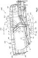
- Fig. 2 the Gelegeportal 100 with a designed here as a scaffold construction receptacle 10 for providing a molding 200 for a preform and a rolling tool holder 20 and a Klebewerkmaschinehalterung 30th Fig. 3
- a Antikwerkmaschinehalterung 40 can be seen.
- the rolling tool holder 20 is used in combination with the adhesive tool holder 30 and then the Antikwerkmaschinehalterung used in combination with the adhesive tool holder 30.
- the rolling tool holder and the Anyakwerkmaschineung is formed as a bridge, which can be moved back and forth along with a similarly slightly modified bridge for the Klebsterkmaschinehalterung 30 on a rail-like to the molding rail system 50 on the molding 200.
- a rolling tool 21 or a pressure tool 41 can be mounted replaceably on the bridge in each case for forming the rolling tool holder 20 or the Andruckwerkmaschineung.
- the girth portal has a catwalk-like catwalk 300, which has a number of platforms 310 and steps 320, in order to be suitably adapted to a height profile of the preform or the molded part.
- a catwalk-like catwalk 300 On the bridge 300 there is sufficient movement and processing room for operators 400 who can support the automated process, observe and optionally remotely control or can also intervene manually in case the observation of the automated process makes this necessary.
- the molded part 200 in the embodiment shown here recognizes the negative shape of a rotor blade, starting from a rotor blade connection region 201, to about one third of the length of the rotor blade.
- a data model for virtual representation 501 of the preform is deposited in the device for control and / or regulation 500 as well as a coordinated line and / or edge model for representing seams, overlapping areas, boundary regions or other suitable for the attachment of adhesive lines and surfaces structural model.
- Such a structural model can serve as the basis for a coordinated and stored in the device 500 movement pattern 503, which serves as the basis for the output to the control and control lines 510, 520, 530, 540 motion signals.
- This is in Fig. 2 and Fig. 3 represented by corresponding data flow lines 504 to the control and regulation lines 510, 520, 530, 540.
- Fig. 2 and Fig. 3 recognizable sequence of movements consists in this embodiment, starting from a narrow side of the molding 200, here the hub side of the rotor blade 201, at the same time in a first working path - referred to here as way - insert a Strukturgelegematte on the Rolltechnikmaschinehalterung the tool assembly 100 and in the same work path adhesive over the Adhesive tool holder 30 on the Strukturgelegematte at suitable splices - for example, following the seam, border or overlap areas according to the structural model 502 - attach.
- the forward movement of the first working path is present as AW1 in Fig. 2 displayed.
- a second commute AW2 - here as a way back or forth - is in Fig. 3 shown.
- the second working travel AW2 extends from the end region 202 of the molding to the hub region 201 of the rotor blade.
- the second working AW2 as in Fig. 3 shown, optionally applied again adhesive on the meanwhile inserted textured mat and pressed the textured mat with a subsequent Andruckwerkmaschinechthalterung.
- first and second working AW1, AW2 are exemplified as opposite working paths.
- the replacement of the rolling tool of the rolling tool holder 20 by a pressing tool of the Antikwerkmaschinehalterung 40 in the end portion 202 of the molding for initiating the movement is meant by example.
- the tool holders 20, 30, 40 mounted side by side in this order in a unidirectional first working AW1 insert a Strukturgelegematte, apply adhesive and press.
- each working path can be made only unidirectional and only by inserting or pressing the Strukturgelegematte.
- Both of an embodiment's possibilities may be combined to form a preform and used as needed in relation to the individual requirements for mounting a structural geometatte within the preform.
- Certain textured laid mats can be laid, for example, by means of a reciprocating motion, others perhaps only by a unidirectional working path.
- the way of organizing work paths and corresponding movement patterns for this tooling system 100 is reserved for the coordinated movement pattern 503, which takes into account the individual needs of the preform based on the data model 501 or the structural model mats structure model 502.
- the tool holder 20 has a rolling tool 21 in such a way that a gel roll 22 can be rotatably rotated with a suitable unrolling speed given by the movement pattern or advanced on the guidance system. Also, in the movement pattern 503, start and stop movements for fixing are given in the frame of the detail operations to step SIII1.
- the adhesive tool holder 30 which carries an adhesive applicator 31, in the present case in the form of a Fassklebesystems for the application of adhesive in the form of hot glue.
- the adhesive can be applied via a line system 32 with two applicator arms 32.1, 32.2 in the present case to a textured laid mat on the adhesive areas predetermined by the movement pattern 503.
- PUR-based hot melt adhesives are suitable. In particular, it is also suitable for any other epoxy resin Formull mecanic an adhesive, especially if it is free of Ausheilungsagenzien or solvents.
- the application of the adhesive takes place by spraying or flowing at an elevated temperature of regularly above 100 °, while the textured mats have a temperature usually not above 40 °, ie, for example, at room temperature with an adhesive temperature of about 115 ° C.
- the drum melter of the adhesive applicator 31 may be provided in various embodiments and variations. It is also a doubled Fassschmelzersystem of at least two Fassschmelzern to ensure continuous operation when one of the barrel melter is emptied.
- Preferred adhesives are reactive adhesives such as PUR. It turns out, however, that other adhesives are also suitable.
- the adhesive applicator 31 has a barrel receptacle 31.1 with a suitable metering system for operating the line system 32, for example a suitable pressure control and three-phase motor for metering action of pumps.
- the adhesive applicator has a suitable robotics 31.2 for positioning and handling of the components as well as a control and operating terminal 31.3, which also ensures the power supply and other operating and logistics and monitoring operations for the adhesive applicator 31.
- the operating activities and machine conditions can also be remotely controlled via 31.3, without operators 400 having to stand directly on the adhesive applicator 31.
- Fig. 3 shows an automated processing situation of the preform after the laid-in textured mat in a second working AW2.
- the operation provides for a second application of adhesive with the adhesive applicator 31 to the glue tool holder 30.
- this is not mandatory, but nevertheless optional,
- the operator 400 determines that sufficient adhesive has not been applied during the first travel AW1; This could be made up in the second working AW2 and subsequently subsequently pressed on the Antikwerkmaschineung 40 previously engaged Strukturgelegematte to the molding 200 or previously inserted adjacent or overlapping Strukturgelegematten.
- a first, still partially rolled-up textured mat 1 is in Fig. 2 shown symbolically.
- the partially unwound and partially inserted textured mat is referred to as 2 in Fig. 2 is shown, and the fully inserted and now pressed on structural mat is in Fig. 3 shown as 3.
- the pressure tool 41 has in the present case a number of three pressure rollers 41.1, 41.2, 41.3, which are each rotatably supported on an arm 42.1, 42.2, 42.3 of a holding system 42.
- the arm system or each of the arms 42.1, 42.2, 42.3 also has corresponding actuators, which convert a pressing force of the rollers 41.1, 41.2, 41.3 onto the texturedlay mat 3 and optionally other areas of the preform in the mold 200 according to the movement pattern 503.
- the structural structure of the partially finished preform into the curvature for example the lateral wall curvature 204 or 206, of the molded part pressed in to optimally adapt the structure of the contour of the molding 200.
- this also applies to the largely horizontally oriented region 205 of the molded part 200.
- strongly curved or high regions, such as the regions 204, 206, in the molded part 200 can now be machined with the same quality as a substantially horizontal part 205 of the molded part 200; Given different curvature or orientation given availability differences have thus no longer influence on the optimal design of the structure; The latter is mainly influenced by the application of adhesive and pressure conditions.
- the device has very considerable advantages in expanding quality management and individual handling of each individual preform or molded part 200.
- the structural composition with a number of flat structures of the textured laid mats can thus be adapted in an optimized manner to the contour of the preform or of the molded part 200 on the basis of the method automation and constructive specification of the collating portal 1000 described hereinbefore shows that the embodiment described here can be particularly well integrated into a larger automated storage and retrieval process and a fully automated rotor blade production.
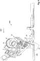
- FIG. 4 a part of the device according to the invention 1000 (Gelegeportal) is shown in a spatial side view. Shown is in FIG. 4 a rolling process of the textured mat in the direction of AW1.
- the rolling roller 22 held and unrolled by the rolling tool 21 is deflected by a dancer roller 23 before reaching the molded part 200.
- a Strukturge privilegemattenabêt 24 between the Gelegerolle 22 and the molding 200 by.
- the dancer roll 23 is movable in the direction of the arrow 25, in particular pivotally and / or translationally movable in order to be able to vary the amount of sagging in section 24.
- the tool holder 20 includes sensor means (not shown) for detecting the tension.
- the sensor means detect either from a fixed attachment to the tool holder 20 from the distance to the Strukturgelegematte in the section 24, or a position of the dancer roll 23.
- the rolling tool 21 and a drive of the dancer roll 23 are signal-conducting with the controller 500th connected (data connection not shown) to control the unwinding speed of the rolling tool 21 and the position of the dancer roller 25 so coordinated that the tensile stress acting on the Strukturgelegematte remains in a predetermined range.
- the predetermined range of the tensile stress is to be selected in preliminary tests so that it does not come to a drape depending on the material of the textured mat, but also no high tensile stress occurs that a molding of the textured mat on the molded part is difficult or prevented.
Landscapes
- Engineering & Computer Science (AREA)
- Mechanical Engineering (AREA)
- Chemical & Material Sciences (AREA)
- Composite Materials (AREA)
- Robotics (AREA)
- Moulding By Coating Moulds (AREA)
- Treatment Of Fiber Materials (AREA)
- Casting Or Compression Moulding Of Plastics Or The Like (AREA)
- Nonwoven Fabrics (AREA)
- Laminated Bodies (AREA)
- Reinforced Plastic Materials (AREA)
- Blow-Moulding Or Thermoforming Of Plastics Or The Like (AREA)
- Processing And Handling Of Plastics And Other Materials For Molding In General (AREA)
Applications Claiming Priority (2)
| Application Number | Priority Date | Filing Date | Title |
|---|---|---|---|
| DE102012219267.0A DE102012219267A1 (de) | 2012-10-22 | 2012-10-22 | Verfahren und Vorrichtung zur Herstellung von Vorformlingen zum Herstellen eines Rotorblattes |
| PCT/EP2013/071405 WO2014063944A1 (de) | 2012-10-22 | 2013-10-14 | Verfahren und vorrichtung zur herstellung von vorformlingen zum herstellen eines rotorblattes |
Publications (2)
| Publication Number | Publication Date |
|---|---|
| EP2908996A1 EP2908996A1 (de) | 2015-08-26 |
| EP2908996B1 true EP2908996B1 (de) | 2019-04-17 |
Family
ID=49378277
Family Applications (1)
| Application Number | Title | Priority Date | Filing Date |
|---|---|---|---|
| EP13777035.0A Active EP2908996B1 (de) | 2012-10-22 | 2013-10-14 | Verfahren und vorrichtung zur herstellung von vorformlingen zum herstellen eines rotorblattes |
Country Status (21)
| Country | Link |
|---|---|
| US (1) | US20150273771A1 (es) |
| EP (1) | EP2908996B1 (es) |
| JP (1) | JP6147352B2 (es) |
| KR (1) | KR101775251B1 (es) |
| CN (1) | CN104755241A (es) |
| AR (1) | AR094535A1 (es) |
| AU (1) | AU2013336866B2 (es) |
| BR (1) | BR112015008726A2 (es) |
| CA (1) | CA2887566C (es) |
| CL (1) | CL2015000983A1 (es) |
| DE (1) | DE102012219267A1 (es) |
| DK (1) | DK2908996T3 (es) |
| ES (1) | ES2734184T3 (es) |
| IN (1) | IN2015DN03107A (es) |
| MX (1) | MX368169B (es) |
| NZ (1) | NZ706805A (es) |
| PT (1) | PT2908996T (es) |
| RU (1) | RU2609169C2 (es) |
| TW (1) | TWI623415B (es) |
| WO (1) | WO2014063944A1 (es) |
| ZA (1) | ZA201502266B (es) |
Families Citing this family (25)
| Publication number | Priority date | Publication date | Assignee | Title |
|---|---|---|---|---|
| FR3029134B1 (fr) * | 2014-12-02 | 2017-10-06 | Snecma | Procede de controle de position d'une preforme d'aube composite de turbomachine dans un moule |
| DE102015106776A1 (de) * | 2015-04-30 | 2016-11-03 | Veit Gmbh | Verfahren zum Betreiben einer Fixiermaschine sowie Fixiermaschine |
| US9897065B2 (en) | 2015-06-29 | 2018-02-20 | General Electric Company | Modular wind turbine rotor blades and methods of assembling same |
| US10337490B2 (en) | 2015-06-29 | 2019-07-02 | General Electric Company | Structural component for a modular rotor blade |
| US10077758B2 (en) | 2015-06-30 | 2018-09-18 | General Electric Company | Corrugated pre-cured laminate plates for use within wind turbine rotor blades |
| US10072632B2 (en) | 2015-06-30 | 2018-09-11 | General Electric Company | Spar cap for a wind turbine rotor blade formed from pre-cured laminate plates of varying thicknesses |
| GB201512366D0 (en) * | 2015-07-15 | 2015-08-19 | Lm Wp Patent Holding As | Mould structure for manufacturing a wind turbine blade |
| US9951750B2 (en) | 2015-07-30 | 2018-04-24 | General Electric Company | Rotor blade with interior shelf for a flat plate spar cap |
| US10669984B2 (en) | 2015-09-22 | 2020-06-02 | General Electric Company | Method for manufacturing blade components using pre-cured laminate materials |
| US10107257B2 (en) | 2015-09-23 | 2018-10-23 | General Electric Company | Wind turbine rotor blade components formed from pultruded hybrid-resin fiber-reinforced composites |
| US9981433B2 (en) * | 2015-09-23 | 2018-05-29 | General Electric Company | Methods for modifying wind turbine blade molds |
| US10113532B2 (en) | 2015-10-23 | 2018-10-30 | General Electric Company | Pre-cured composites for rotor blade components |
| EP3492248B1 (en) * | 2016-07-27 | 2021-08-25 | Mitsubishi Chemical Corporation | Preform production apparatus and preform production method |
| US10422316B2 (en) | 2016-08-30 | 2019-09-24 | General Electric Company | Pre-cured rotor blade components having areas of variable stiffness |
| DE102016013637A1 (de) * | 2016-11-16 | 2018-05-17 | Carbon Rotec Gmbh & Co. Kg | Modul für ein Laufgestell |
| US10527023B2 (en) | 2017-02-09 | 2020-01-07 | General Electric Company | Methods for manufacturing spar caps for wind turbine rotor blades |
| US10738759B2 (en) | 2017-02-09 | 2020-08-11 | General Electric Company | Methods for manufacturing spar caps for wind turbine rotor blades |
| DE102017001402A1 (de) * | 2017-02-14 | 2018-08-16 | Senvion Gmbh | Zentriereinrichtung an der Hinterkante der Formhalbschalen |
| CN107696525A (zh) * | 2017-09-30 | 2018-02-16 | 株洲时代新材料科技股份有限公司 | 一种风电叶片模具用铺布装置 |
| US10677216B2 (en) | 2017-10-24 | 2020-06-09 | General Electric Company | Wind turbine rotor blade components formed using pultruded rods |
| US11738530B2 (en) | 2018-03-22 | 2023-08-29 | General Electric Company | Methods for manufacturing wind turbine rotor blade components |
| CN112327755B (zh) * | 2020-11-16 | 2021-09-14 | 广州傲创智能科技有限公司 | 一种模架的框被自动识别的方法 |
| CN113199779A (zh) * | 2021-05-11 | 2021-08-03 | 中材科技(锡林郭勒)风电叶片有限公司 | 风电叶片模具装配系统 |
| CN113650325B (zh) * | 2021-07-28 | 2022-12-02 | 苏州通五洲科技有限公司 | 封闭式胶衣物料混合设备 |
| US20230063490A1 (en) * | 2021-08-30 | 2023-03-02 | The Boeing Company | Forming apparatus, methods, and systems |
Citations (1)
| Publication number | Priority date | Publication date | Assignee | Title |
|---|---|---|---|---|
| WO2011047167A1 (en) * | 2009-10-16 | 2011-04-21 | Gerber Scientific International, Inc. | Methods and systems for manufacturing composite parts |
Family Cites Families (20)
| Publication number | Priority date | Publication date | Assignee | Title |
|---|---|---|---|---|
| GB487050A (en) * | 1936-11-14 | 1938-06-14 | John Louis Hugimer Murray | Improvements in or relating to the roofing and covering of buildings and the glazing of greenhouses, frames and building structures in general |
| US2410888A (en) * | 1944-03-31 | 1946-11-12 | Murray Lucy Marvosh Company | Method and apparatus for molding three-dimensional shapes from drawings |
| US4731144A (en) * | 1986-07-14 | 1988-03-15 | Harris Corporation | Method of shaping an antenna panel |
| JPH11139515A (ja) * | 1997-11-07 | 1999-05-25 | Sekisui Chem Co Ltd | 原材料ロールの在庫管理方法 |
| FR2853914B1 (fr) * | 2003-04-17 | 2005-11-25 | Hexcel Fabrics | Procede et installation de fabrication d'une preforme de renfort |
| US7341086B2 (en) * | 2004-10-29 | 2008-03-11 | The Boeing Company | Automated fabric layup system and method |
| FR2882356B1 (fr) * | 2005-02-23 | 2008-08-15 | Snecma Propulsion Solide Sa | Procede de fabrication de piece en materiau composite a matrice ceramique et piece ainsi obtenue |
| DE102005044823B3 (de) * | 2005-09-20 | 2007-05-16 | Airbus Gmbh | Verfahren und Vorrichtung zum Aufbringen dünner Materiallagen auf eine Reliefform |
| DE102006021110B4 (de) * | 2006-05-05 | 2011-04-21 | Airbus Operations Gmbh | Vorrichtung und Verfahren zum Herstellen eines großflächigen Faserverbund-Strukturbauteils |
| DE102006052592B4 (de) * | 2006-11-08 | 2013-09-12 | Eads Deutschland Gmbh | Verfahren zur Ablage großer trockener Textilfaserbahnen |
| US9770871B2 (en) * | 2007-05-22 | 2017-09-26 | The Boeing Company | Method and apparatus for layup placement |
| DE102008004261B3 (de) * | 2008-01-14 | 2009-04-16 | Universität Bremen | Verfahren und Vorrichtung zum Ablegen eines aufgerollten Materials |
| WO2009156157A1 (de) * | 2008-06-25 | 2009-12-30 | Zsk Stickmaschinen Gmbh | Vorrichtung und verfahren zum aufbringen eines bandförmigen materials |
| US20120138218A1 (en) * | 2009-05-04 | 2012-06-07 | Mag Ias, Llc | Rapid material placement application for wind turbine blade manufacture |
| ES2365571B1 (es) * | 2009-05-21 | 2012-09-17 | Danobat S.Coop | Sistema para la fabricacion automatica de palas de aerogenerador |
| FR2950285A1 (fr) * | 2009-09-21 | 2011-03-25 | Airbus Operations Sas | Dispositif de drapage automatise |
| JP5751751B2 (ja) * | 2009-12-25 | 2015-07-22 | 三菱重工業株式会社 | 強化繊維基材積層装置およびこの積層方法 |
| DE102010004530A1 (de) * | 2010-01-14 | 2011-07-21 | Bayerische Motoren Werke Aktiengesellschaft, 80809 | Verfahren zum Herstellen einer Versteifungsmatrix für ein Kunststoffteil |
| DE102010012719A1 (de) * | 2010-03-25 | 2011-09-29 | Daimler Ag | Legekopfkompaktvorrichtung, Legeanlage und Verfahren zur Herstellung einer Preform |
| GB2487050A (en) * | 2011-01-04 | 2012-07-11 | Vestas Wind Sys As | Automated techniques for manufacturing fibrous panels |
-
2012
- 2012-10-22 DE DE102012219267.0A patent/DE102012219267A1/de not_active Withdrawn
-
2013
- 2013-10-14 KR KR1020157013385A patent/KR101775251B1/ko active IP Right Grant
- 2013-10-14 JP JP2015537208A patent/JP6147352B2/ja not_active Expired - Fee Related
- 2013-10-14 ES ES13777035T patent/ES2734184T3/es active Active
- 2013-10-14 NZ NZ706805A patent/NZ706805A/en not_active IP Right Cessation
- 2013-10-14 IN IN3107DEN2015 patent/IN2015DN03107A/en unknown
- 2013-10-14 CA CA2887566A patent/CA2887566C/en not_active Expired - Fee Related
- 2013-10-14 CN CN201380054940.2A patent/CN104755241A/zh active Pending
- 2013-10-14 MX MX2015005022A patent/MX368169B/es active IP Right Grant
- 2013-10-14 PT PT13777035T patent/PT2908996T/pt unknown
- 2013-10-14 BR BR112015008726A patent/BR112015008726A2/pt active Search and Examination
- 2013-10-14 US US14/437,422 patent/US20150273771A1/en not_active Abandoned
- 2013-10-14 AU AU2013336866A patent/AU2013336866B2/en not_active Ceased
- 2013-10-14 EP EP13777035.0A patent/EP2908996B1/de active Active
- 2013-10-14 DK DK13777035.0T patent/DK2908996T3/da active
- 2013-10-14 RU RU2015119263A patent/RU2609169C2/ru not_active IP Right Cessation
- 2013-10-14 WO PCT/EP2013/071405 patent/WO2014063944A1/de active Application Filing
- 2013-10-21 TW TW102137960A patent/TWI623415B/zh not_active IP Right Cessation
- 2013-10-22 AR ARP130103815A patent/AR094535A1/es active IP Right Grant
-
2015
- 2015-04-07 ZA ZA2015/02266A patent/ZA201502266B/en unknown
- 2015-04-17 CL CL2015000983A patent/CL2015000983A1/es unknown
Patent Citations (1)
| Publication number | Priority date | Publication date | Assignee | Title |
|---|---|---|---|---|
| WO2011047167A1 (en) * | 2009-10-16 | 2011-04-21 | Gerber Scientific International, Inc. | Methods and systems for manufacturing composite parts |
Also Published As
| Publication number | Publication date |
|---|---|
| US20150273771A1 (en) | 2015-10-01 |
| AU2013336866B2 (en) | 2017-02-09 |
| CA2887566C (en) | 2018-03-06 |
| WO2014063944A1 (de) | 2014-05-01 |
| EP2908996A1 (de) | 2015-08-26 |
| IN2015DN03107A (es) | 2015-10-02 |
| NZ706805A (en) | 2016-08-26 |
| JP6147352B2 (ja) | 2017-06-21 |
| CL2015000983A1 (es) | 2015-08-28 |
| MX368169B (es) | 2019-09-23 |
| JP2016500587A (ja) | 2016-01-14 |
| KR101775251B1 (ko) | 2017-09-05 |
| PT2908996T (pt) | 2019-07-23 |
| DE102012219267A1 (de) | 2014-04-24 |
| RU2609169C2 (ru) | 2017-01-30 |
| KR20150076222A (ko) | 2015-07-06 |
| DK2908996T3 (da) | 2019-07-01 |
| TWI623415B (zh) | 2018-05-11 |
| CN104755241A (zh) | 2015-07-01 |
| TW201429695A (zh) | 2014-08-01 |
| MX2015005022A (es) | 2015-10-26 |
| ZA201502266B (en) | 2016-01-27 |
| BR112015008726A2 (pt) | 2017-07-04 |
| AU2013336866A1 (en) | 2015-04-30 |
| CA2887566A1 (en) | 2014-05-01 |
| ES2734184T3 (es) | 2019-12-04 |
| RU2015119263A (ru) | 2016-12-10 |
| AR094535A1 (es) | 2015-08-12 |
Similar Documents
| Publication | Publication Date | Title |
|---|---|---|
| EP2908996B1 (de) | Verfahren und vorrichtung zur herstellung von vorformlingen zum herstellen eines rotorblattes | |
| DE102008042574B4 (de) | Vorrichtung zum Ablegen und Drapieren von Abschnitten einer Verstärkungsfaserstruktur zur Herstellung eines Profilvorformlings sowie Verfahren | |
| EP3377308B1 (de) | Fertigungsanlage zum legen von faserbändern | |
| DE102006052592B4 (de) | Verfahren zur Ablage großer trockener Textilfaserbahnen | |
| DE102008011410B4 (de) | Pultrusionsverfahren zur Herstellung eines profilierten Preforms oder eines profilierten FVK-Bauteils, Pultrusionsanlage sowie Press-Vorrichtung zur Durchführung des Verfahrens | |
| EP2694263B1 (de) | Vorrichtung und verfahren zur herstellung von faservorformlingen, die insbesondere eine vorstufe bei der herstellung von faserverstärkten kunststoff-bauteilen darstellen | |
| DE60118048T2 (de) | Verfahren und Anlage zur kontinuierlichen Herstellung eines H-formigen Gegenstands aus faserverstärktem Kunststoff | |
| EP2280820B1 (de) | Verfahren zur herstellung eines fvw/fvk-bauteils aus rovings mit einem formwerkzeug und formwerkzeug zur durchführung des verfahrens | |
| WO2002007944A2 (de) | Verfahren und produktionsanlage zum herstellen von schalenförmigen, fasermatten-verstärkten kunststoffteilen | |
| DE112015002058T5 (de) | Vorrichtung und Verfahren zur Ausbildung von dreidimensionalen Objekten | |
| EP3678851B1 (de) | Fertigungsanlage und verfahren zum legen von faserbändern | |
| EP2917020B1 (de) | Vorrichtung und verfahren zum herstellen von halbzeugen fuer windenergieanlagen-rotorblaetter | |
| EP2694262A1 (de) | Vorrichtung und verfahren zur herstellung von faservorformlingen, die insbesondere eine vorstufe bei der herstellung von faserverstärkten kunststoff-bauteilen darstellen | |
| DE10050851A1 (de) | Verfahren zur Herstellung von Vorformlingen aus Faser-Verbund-Materialien, sowie ein daraus hergestellter Vorformling | |
| WO2012136392A1 (de) | Vorrichtung und verfahren zur herstellung von faservorformlingen, die insbesondere eine vorstufe bei der herstellung von faserverstärkten kunststoff-bauteilen darstellen | |
| EP3012093B1 (de) | Verfahren und anordnung zur herstellung einer blattfeder | |
| DE102013104609B4 (de) | Nestingablage | |
| EP3294533B1 (de) | Greifer mit zumindest einem klemmelement | |
| DE102008004261B3 (de) | Verfahren und Vorrichtung zum Ablegen eines aufgerollten Materials | |
| AT512984A2 (de) | Vorrichtung und Verfahren zur Aufnahme und Transport von einzelnen Textilbahnen oder Stapeln von Textilbahnen | |
| EP0800449B1 (de) | Verfahren und vorrichtung zur herstellung von verstärkungseinlagen für werkstoffverbunde, insbesondere schleif- oder trennscheiben | |
| EP0308539A1 (de) | Verfahren zum Ausrichten einer konkreten bzw. wirklichen Fläche, z. B. einer Form, auf ein internes Koordinatensystem einer sich relativ zu ihr bewegenden Maschine, insbesondere einer Mehrachsen-Bandlegemaschine sowie Positionierungssystem bzw. -vorrichtung zur Durchführung des verfahrens | |
| DE202016100440U1 (de) | Werkzeug zum Drapieren eines Faserzuschnitts zur Herstellung eines dreidimensionalen Vorformlings |
Legal Events
| Date | Code | Title | Description |
|---|---|---|---|
| PUAI | Public reference made under article 153(3) epc to a published international application that has entered the european phase |
Free format text: ORIGINAL CODE: 0009012 |
|
| 17P | Request for examination filed |
Effective date: 20150522 |
|
| AK | Designated contracting states |
Kind code of ref document: A1 Designated state(s): AL AT BE BG CH CY CZ DE DK EE ES FI FR GB GR HR HU IE IS IT LI LT LU LV MC MK MT NL NO PL PT RO RS SE SI SK SM TR |
|
| AX | Request for extension of the european patent |
Extension state: BA ME |
|
| RAP1 | Party data changed (applicant data changed or rights of an application transferred) |
Owner name: WOBBEN PROPERTIES GMBH |
|
| STAA | Information on the status of an ep patent application or granted ep patent |
Free format text: STATUS: EXAMINATION IS IN PROGRESS |
|
| 17Q | First examination report despatched |
Effective date: 20170627 |
|
| GRAP | Despatch of communication of intention to grant a patent |
Free format text: ORIGINAL CODE: EPIDOSNIGR1 |
|
| STAA | Information on the status of an ep patent application or granted ep patent |
Free format text: STATUS: GRANT OF PATENT IS INTENDED |
|
| INTG | Intention to grant announced |
Effective date: 20181106 |
|
| GRAS | Grant fee paid |
Free format text: ORIGINAL CODE: EPIDOSNIGR3 |
|
| GRAA | (expected) grant |
Free format text: ORIGINAL CODE: 0009210 |
|
| STAA | Information on the status of an ep patent application or granted ep patent |
Free format text: STATUS: THE PATENT HAS BEEN GRANTED |
|
| REG | Reference to a national code |
Ref country code: DE Ref legal event code: R082 Ref document number: 502013012664 Country of ref document: DE Representative=s name: EISENFUEHR SPEISER PATENTANWAELTE RECHTSANWAEL, DE |
|
| AK | Designated contracting states |
Kind code of ref document: B1 Designated state(s): AL AT BE BG CH CY CZ DE DK EE ES FI FR GB GR HR HU IE IS IT LI LT LU LV MC MK MT NL NO PL PT RO RS SE SI SK SM TR |
|
| AX | Request for extension of the european patent |
Extension state: BA ME |
|
| REG | Reference to a national code |
Ref country code: GB Ref legal event code: FG4D Free format text: NOT ENGLISH |
|
| REG | Reference to a national code |
Ref country code: CH Ref legal event code: EP |
|
| REG | Reference to a national code |
Ref country code: DE Ref legal event code: R096 Ref document number: 502013012664 Country of ref document: DE |
|
| REG | Reference to a national code |
Ref country code: AT Ref legal event code: REF Ref document number: 1121051 Country of ref document: AT Kind code of ref document: T Effective date: 20190515 Ref country code: IE Ref legal event code: FG4D Free format text: LANGUAGE OF EP DOCUMENT: GERMAN |
|
| REG | Reference to a national code |
Ref country code: NL Ref legal event code: FP |
|
| REG | Reference to a national code |
Ref country code: DK Ref legal event code: T3 Effective date: 20190627 |
|
| REG | Reference to a national code |
Ref country code: SE Ref legal event code: TRGR Ref country code: PT Ref legal event code: SC4A Ref document number: 2908996 Country of ref document: PT Date of ref document: 20190723 Kind code of ref document: T Free format text: AVAILABILITY OF NATIONAL TRANSLATION Effective date: 20190716 |
|
| REG | Reference to a national code |
Ref country code: LT Ref legal event code: MG4D |
|
| PG25 | Lapsed in a contracting state [announced via postgrant information from national office to epo] |
Ref country code: AL Free format text: LAPSE BECAUSE OF FAILURE TO SUBMIT A TRANSLATION OF THE DESCRIPTION OR TO PAY THE FEE WITHIN THE PRESCRIBED TIME-LIMIT Effective date: 20190417 Ref country code: HR Free format text: LAPSE BECAUSE OF FAILURE TO SUBMIT A TRANSLATION OF THE DESCRIPTION OR TO PAY THE FEE WITHIN THE PRESCRIBED TIME-LIMIT Effective date: 20190417 Ref country code: LT Free format text: LAPSE BECAUSE OF FAILURE TO SUBMIT A TRANSLATION OF THE DESCRIPTION OR TO PAY THE FEE WITHIN THE PRESCRIBED TIME-LIMIT Effective date: 20190417 Ref country code: FI Free format text: LAPSE BECAUSE OF FAILURE TO SUBMIT A TRANSLATION OF THE DESCRIPTION OR TO PAY THE FEE WITHIN THE PRESCRIBED TIME-LIMIT Effective date: 20190417 Ref country code: NO Free format text: LAPSE BECAUSE OF FAILURE TO SUBMIT A TRANSLATION OF THE DESCRIPTION OR TO PAY THE FEE WITHIN THE PRESCRIBED TIME-LIMIT Effective date: 20190717 |
|
| PG25 | Lapsed in a contracting state [announced via postgrant information from national office to epo] |
Ref country code: RS Free format text: LAPSE BECAUSE OF FAILURE TO SUBMIT A TRANSLATION OF THE DESCRIPTION OR TO PAY THE FEE WITHIN THE PRESCRIBED TIME-LIMIT Effective date: 20190417 Ref country code: GR Free format text: LAPSE BECAUSE OF FAILURE TO SUBMIT A TRANSLATION OF THE DESCRIPTION OR TO PAY THE FEE WITHIN THE PRESCRIBED TIME-LIMIT Effective date: 20190718 Ref country code: PL Free format text: LAPSE BECAUSE OF FAILURE TO SUBMIT A TRANSLATION OF THE DESCRIPTION OR TO PAY THE FEE WITHIN THE PRESCRIBED TIME-LIMIT Effective date: 20190417 Ref country code: BG Free format text: LAPSE BECAUSE OF FAILURE TO SUBMIT A TRANSLATION OF THE DESCRIPTION OR TO PAY THE FEE WITHIN THE PRESCRIBED TIME-LIMIT Effective date: 20190717 Ref country code: LV Free format text: LAPSE BECAUSE OF FAILURE TO SUBMIT A TRANSLATION OF THE DESCRIPTION OR TO PAY THE FEE WITHIN THE PRESCRIBED TIME-LIMIT Effective date: 20190417 |
|
| REG | Reference to a national code |
Ref country code: ES Ref legal event code: FG2A Ref document number: 2734184 Country of ref document: ES Kind code of ref document: T3 Effective date: 20191204 |
|
| PG25 | Lapsed in a contracting state [announced via postgrant information from national office to epo] |
Ref country code: IS Free format text: LAPSE BECAUSE OF FAILURE TO SUBMIT A TRANSLATION OF THE DESCRIPTION OR TO PAY THE FEE WITHIN THE PRESCRIBED TIME-LIMIT Effective date: 20190817 |
|
| REG | Reference to a national code |
Ref country code: DE Ref legal event code: R097 Ref document number: 502013012664 Country of ref document: DE |
|
| PG25 | Lapsed in a contracting state [announced via postgrant information from national office to epo] |
Ref country code: SK Free format text: LAPSE BECAUSE OF FAILURE TO SUBMIT A TRANSLATION OF THE DESCRIPTION OR TO PAY THE FEE WITHIN THE PRESCRIBED TIME-LIMIT Effective date: 20190417 Ref country code: RO Free format text: LAPSE BECAUSE OF FAILURE TO SUBMIT A TRANSLATION OF THE DESCRIPTION OR TO PAY THE FEE WITHIN THE PRESCRIBED TIME-LIMIT Effective date: 20190417 Ref country code: CZ Free format text: LAPSE BECAUSE OF FAILURE TO SUBMIT A TRANSLATION OF THE DESCRIPTION OR TO PAY THE FEE WITHIN THE PRESCRIBED TIME-LIMIT Effective date: 20190417 Ref country code: EE Free format text: LAPSE BECAUSE OF FAILURE TO SUBMIT A TRANSLATION OF THE DESCRIPTION OR TO PAY THE FEE WITHIN THE PRESCRIBED TIME-LIMIT Effective date: 20190417 |
|
| PGFP | Annual fee paid to national office [announced via postgrant information from national office to epo] |
Ref country code: SE Payment date: 20191023 Year of fee payment: 7 Ref country code: PT Payment date: 20191014 Year of fee payment: 7 |
|
| PLBE | No opposition filed within time limit |
Free format text: ORIGINAL CODE: 0009261 |
|
| STAA | Information on the status of an ep patent application or granted ep patent |
Free format text: STATUS: NO OPPOSITION FILED WITHIN TIME LIMIT |
|
| PG25 | Lapsed in a contracting state [announced via postgrant information from national office to epo] |
Ref country code: SM Free format text: LAPSE BECAUSE OF FAILURE TO SUBMIT A TRANSLATION OF THE DESCRIPTION OR TO PAY THE FEE WITHIN THE PRESCRIBED TIME-LIMIT Effective date: 20190417 Ref country code: IT Free format text: LAPSE BECAUSE OF FAILURE TO SUBMIT A TRANSLATION OF THE DESCRIPTION OR TO PAY THE FEE WITHIN THE PRESCRIBED TIME-LIMIT Effective date: 20190417 |
|
| PGFP | Annual fee paid to national office [announced via postgrant information from national office to epo] |
Ref country code: ES Payment date: 20191120 Year of fee payment: 7 |
|
| 26N | No opposition filed |
Effective date: 20200120 |
|
| PG25 | Lapsed in a contracting state [announced via postgrant information from national office to epo] |
Ref country code: TR Free format text: LAPSE BECAUSE OF FAILURE TO SUBMIT A TRANSLATION OF THE DESCRIPTION OR TO PAY THE FEE WITHIN THE PRESCRIBED TIME-LIMIT Effective date: 20190417 |
|
| PGFP | Annual fee paid to national office [announced via postgrant information from national office to epo] |
Ref country code: AT Payment date: 20191018 Year of fee payment: 7 |
|
| PG25 | Lapsed in a contracting state [announced via postgrant information from national office to epo] |
Ref country code: MC Free format text: LAPSE BECAUSE OF FAILURE TO SUBMIT A TRANSLATION OF THE DESCRIPTION OR TO PAY THE FEE WITHIN THE PRESCRIBED TIME-LIMIT Effective date: 20190417 Ref country code: SI Free format text: LAPSE BECAUSE OF FAILURE TO SUBMIT A TRANSLATION OF THE DESCRIPTION OR TO PAY THE FEE WITHIN THE PRESCRIBED TIME-LIMIT Effective date: 20190417 |
|
| REG | Reference to a national code |
Ref country code: CH Ref legal event code: PL |
|
| PG25 | Lapsed in a contracting state [announced via postgrant information from national office to epo] |
Ref country code: CH Free format text: LAPSE BECAUSE OF NON-PAYMENT OF DUE FEES Effective date: 20191031 Ref country code: LI Free format text: LAPSE BECAUSE OF NON-PAYMENT OF DUE FEES Effective date: 20191031 Ref country code: LU Free format text: LAPSE BECAUSE OF NON-PAYMENT OF DUE FEES Effective date: 20191014 |
|
| REG | Reference to a national code |
Ref country code: BE Ref legal event code: MM Effective date: 20191031 |
|
| PG25 | Lapsed in a contracting state [announced via postgrant information from national office to epo] |
Ref country code: BE Free format text: LAPSE BECAUSE OF NON-PAYMENT OF DUE FEES Effective date: 20191031 |
|
| PG25 | Lapsed in a contracting state [announced via postgrant information from national office to epo] |
Ref country code: IE Free format text: LAPSE BECAUSE OF NON-PAYMENT OF DUE FEES Effective date: 20191014 |
|
| PG25 | Lapsed in a contracting state [announced via postgrant information from national office to epo] |
Ref country code: CY Free format text: LAPSE BECAUSE OF FAILURE TO SUBMIT A TRANSLATION OF THE DESCRIPTION OR TO PAY THE FEE WITHIN THE PRESCRIBED TIME-LIMIT Effective date: 20190417 |
|
| REG | Reference to a national code |
Ref country code: SE Ref legal event code: EUG |
|
| REG | Reference to a national code |
Ref country code: AT Ref legal event code: MM01 Ref document number: 1121051 Country of ref document: AT Kind code of ref document: T Effective date: 20201014 |
|
| PG25 | Lapsed in a contracting state [announced via postgrant information from national office to epo] |
Ref country code: PT Free format text: LAPSE BECAUSE OF NON-PAYMENT OF DUE FEES Effective date: 20210414 Ref country code: MT Free format text: LAPSE BECAUSE OF FAILURE TO SUBMIT A TRANSLATION OF THE DESCRIPTION OR TO PAY THE FEE WITHIN THE PRESCRIBED TIME-LIMIT Effective date: 20190417 Ref country code: HU Free format text: LAPSE BECAUSE OF FAILURE TO SUBMIT A TRANSLATION OF THE DESCRIPTION OR TO PAY THE FEE WITHIN THE PRESCRIBED TIME-LIMIT; INVALID AB INITIO Effective date: 20131014 |
|
| PG25 | Lapsed in a contracting state [announced via postgrant information from national office to epo] |
Ref country code: AT Free format text: LAPSE BECAUSE OF NON-PAYMENT OF DUE FEES Effective date: 20201014 Ref country code: SE Free format text: LAPSE BECAUSE OF NON-PAYMENT OF DUE FEES Effective date: 20201015 |
|
| REG | Reference to a national code |
Ref country code: ES Ref legal event code: FD2A Effective date: 20220121 |
|
| PG25 | Lapsed in a contracting state [announced via postgrant information from national office to epo] |
Ref country code: ES Free format text: LAPSE BECAUSE OF NON-PAYMENT OF DUE FEES Effective date: 20201015 |
|
| PG25 | Lapsed in a contracting state [announced via postgrant information from national office to epo] |
Ref country code: MK Free format text: LAPSE BECAUSE OF FAILURE TO SUBMIT A TRANSLATION OF THE DESCRIPTION OR TO PAY THE FEE WITHIN THE PRESCRIBED TIME-LIMIT Effective date: 20190417 |
|
| PGFP | Annual fee paid to national office [announced via postgrant information from national office to epo] |
Ref country code: NL Payment date: 20231023 Year of fee payment: 11 |
|
| PGFP | Annual fee paid to national office [announced via postgrant information from national office to epo] |
Ref country code: GB Payment date: 20231025 Year of fee payment: 11 |
|
| PGFP | Annual fee paid to national office [announced via postgrant information from national office to epo] |
Ref country code: FR Payment date: 20231023 Year of fee payment: 11 Ref country code: DK Payment date: 20231025 Year of fee payment: 11 Ref country code: DE Payment date: 20231109 Year of fee payment: 11 |