EP2908152B1 - Optoelektronischer Sensor und Verfahren zur Erfassung von Objekten in einem Überwachungsbereich - Google Patents
Optoelektronischer Sensor und Verfahren zur Erfassung von Objekten in einem Überwachungsbereich Download PDFInfo
- Publication number
- EP2908152B1 EP2908152B1 EP14198082.1A EP14198082A EP2908152B1 EP 2908152 B1 EP2908152 B1 EP 2908152B1 EP 14198082 A EP14198082 A EP 14198082A EP 2908152 B1 EP2908152 B1 EP 2908152B1
- Authority
- EP
- European Patent Office
- Prior art keywords
- wheel
- gear
- profile
- axis
- drive
- Prior art date
- Legal status (The legal status is an assumption and is not a legal conclusion. Google has not performed a legal analysis and makes no representation as to the accuracy of the status listed.)
- Active
Links
- 238000000034 method Methods 0.000 title claims description 12
- 230000005693 optoelectronics Effects 0.000 title claims description 6
- 230000033001 locomotion Effects 0.000 claims description 68
- 238000012544 monitoring process Methods 0.000 claims description 11
- 230000009467 reduction Effects 0.000 claims description 11
- 238000011156 evaluation Methods 0.000 claims description 8
- 230000007246 mechanism Effects 0.000 claims description 8
- 230000000694 effects Effects 0.000 claims description 2
- 230000005540 biological transmission Effects 0.000 description 25
- 230000008878 coupling Effects 0.000 description 10
- 238000010168 coupling process Methods 0.000 description 10
- 238000005859 coupling reaction Methods 0.000 description 10
- 238000001514 detection method Methods 0.000 description 8
- 230000003287 optical effect Effects 0.000 description 4
- 230000008901 benefit Effects 0.000 description 3
- 230000008859 change Effects 0.000 description 2
- 238000012423 maintenance Methods 0.000 description 2
- 238000005096 rolling process Methods 0.000 description 2
- 230000003068 static effect Effects 0.000 description 2
- 238000012935 Averaging Methods 0.000 description 1
- 238000013459 approach Methods 0.000 description 1
- 230000004888 barrier function Effects 0.000 description 1
- 238000010276 construction Methods 0.000 description 1
- 230000001419 dependent effect Effects 0.000 description 1
- 238000013461 design Methods 0.000 description 1
- 238000004519 manufacturing process Methods 0.000 description 1
- 230000004048 modification Effects 0.000 description 1
- 238000012986 modification Methods 0.000 description 1
- 238000001208 nuclear magnetic resonance pulse sequence Methods 0.000 description 1
- 230000008569 process Effects 0.000 description 1
- 238000005070 sampling Methods 0.000 description 1
- 238000000926 separation method Methods 0.000 description 1
- 239000007787 solid Substances 0.000 description 1
- 230000001360 synchronised effect Effects 0.000 description 1
Images


Classifications
-
- G—PHYSICS
- G01—MEASURING; TESTING
- G01S—RADIO DIRECTION-FINDING; RADIO NAVIGATION; DETERMINING DISTANCE OR VELOCITY BY USE OF RADIO WAVES; LOCATING OR PRESENCE-DETECTING BY USE OF THE REFLECTION OR RERADIATION OF RADIO WAVES; ANALOGOUS ARRANGEMENTS USING OTHER WAVES
- G01S7/00—Details of systems according to groups G01S13/00, G01S15/00, G01S17/00
- G01S7/48—Details of systems according to groups G01S13/00, G01S15/00, G01S17/00 of systems according to group G01S17/00
- G01S7/481—Constructional features, e.g. arrangements of optical elements
- G01S7/4817—Constructional features, e.g. arrangements of optical elements relating to scanning
-
- G—PHYSICS
- G01—MEASURING; TESTING
- G01S—RADIO DIRECTION-FINDING; RADIO NAVIGATION; DETERMINING DISTANCE OR VELOCITY BY USE OF RADIO WAVES; LOCATING OR PRESENCE-DETECTING BY USE OF THE REFLECTION OR RERADIATION OF RADIO WAVES; ANALOGOUS ARRANGEMENTS USING OTHER WAVES
- G01S17/00—Systems using the reflection or reradiation of electromagnetic waves other than radio waves, e.g. lidar systems
- G01S17/02—Systems using the reflection of electromagnetic waves other than radio waves
- G01S17/06—Systems determining position data of a target
- G01S17/42—Simultaneous measurement of distance and other co-ordinates
-
- G—PHYSICS
- G02—OPTICS
- G02B—OPTICAL ELEMENTS, SYSTEMS OR APPARATUS
- G02B26/00—Optical devices or arrangements for the control of light using movable or deformable optical elements
- G02B26/08—Optical devices or arrangements for the control of light using movable or deformable optical elements for controlling the direction of light
- G02B26/10—Scanning systems
- G02B26/101—Scanning systems with both horizontal and vertical deflecting means, e.g. raster or XY scanners
Definitions
- the invention relates to an optoelectronic sensor and a method for detecting objects according to the preamble of claim 1 and 7, respectively.
- Scanners are used for a variety of monitoring and surveying tasks. For this purpose, a scanning or scanning beam scans an area and evaluates the remitted or reflected light. In order to gain information about object distances, contours or profiles, it is usually not only the presence of objects that is determined but also their distance.
- Such distance-measuring laser scanners operate according to a light transit time principle in which the transit time is measured by the scanner in the scenery and back and distance data are calculated on the basis of the speed of light.
- phase-based methods the light emitter modulates the scan beam and determines the phase between a reference and the received scan beam.
- Pulse-based methods impose a significant pattern on the scan beam, such as a narrow pulse of only a few nanoseconds in duration, and determine the time of reception of that pattern.
- the pulse averaging process a plurality of pulses or a pulse sequence are emitted and the received pulses are statistically evaluated.
- laser scanners are developed into a 3D scanner.
- multi-level scanning can be achieved by using raster mirrors with differently sloped facets as the deflection unit. This results in an angular offset of each belonging to a facet scan plane.
- the scanning angle range of the respective scanning plane is limited to the angular component of the facet of typically less than 100 °.
- Another disadvantageous effect is that only the central scan plane is really a plane, because with increasing inclination of the facets the scan planes are bent unbalanced due to the construction. Especially with a larger fanning out of the scan lines, hardly any usable arcuate scan lines are created.
- an additional deflection unit usually in the form of a vibrating mirror, which ensures a deflection of the scanning beam in a second direction.
- the scanning plane can be pivoted.
- the use of two deflection units results in increased costs and a greater space requirement, thus a high optical and mechanical complexity, in addition to additional transmission and reception signal losses.
- additional oscillating mirror according to DE 20 2009 012 114 U1 the 360 ° scanning range of a rotating mirror is divided. In a front angle range, a surface is scanned in a conventional manner.
- the scanning beam is deflected several times and then falls on a vibrating mirror, which is pivoted in a direction transverse to the deflection of the rotating mirror.
- a space cut is scanned over the rear angle range instead of a surface.
- the monitoring of three-dimensional scanning regions is also achieved in that the rotating mirror and thus the rotation axis and the scanning plane is tilted in addition to the rotational movement.
- the entire scanning unit including transmitter, receiver and rotating mirror is arranged on a Ablenkkteller. By pivoting the Ablenktellers then the scan plane is varied so as to monitor a total of three-dimensional space area. This requires but considerable additional expense for the Ablenkteller and the additional pivot drive.
- the EP 1 965 225 A2 discloses another laser radar apparatus for the three-dimensional detection of objects whose deflection unit is additionally tilted by a variety of proposed mechanisms.
- some embodiments for the tilting movement use a second drive in addition to the rotating motor, for example by bringing a rotating cam into direct contact with the rotating mirror. Accordingly, however, the second drive must be provided, controlled and synchronized.
- two radially offset by 180 ° from each other by the deflection outwardly rotating members are provided with rollers which run in a hollow profile of a guide path. As a result, the rotational movement is superimposed by a tilting movement, which is forced by the geometry of the guide path.
- the presented guide path is unsuitable to extend a scan pattern over more than one revolution and, for example, to form a multilevel scanner.
- the US Pat. No. 6,373,612 B1 discloses a laser scanner whose mirror is incorporated in a mechanism for varying the tilt position.
- a wheel runs in the course of the rotation of the mirror on a height profile in the form of a triangular wave, and the height differences are transmitted via a rack on the horizontal axis of the mirror and thus its tilted position.
- the JP S60 12527 A describes an infrared scanner having a housing with transmitter and receiver and a motor, wherein the motor rotates the housing relative to a carrier in rotation.
- a gear mechanism with multiple gears and rods, the rotational movement is also transmitted to the tilted position of a mirror.
- a scanner for a mobile device is known, the rotating mirror is tilted at the same time.
- a first gear is provided on the vertical axis of the drive for the rotating mirror, which is in threaded engagement with two other gears in a vertical arrangement to the first gear.
- the other gears With the other gears also rotates a perpendicular to the vertical axis horizontal axis on which in turn rotate two cams. They provide by their opposite different radii for the desired tilting movement of a frame of the rotating mirror.
- the object of the invention is to enable the extension of the monitoring range of an optoelectronic sensor by simple means.
- the sensor according to the invention monitors more than just one scanning plane in that its deflection unit, in addition to its rotational movement, performs a tilting movement which varies the axis of rotation and thus the scanning plane.
- the invention is based on the basic idea to couple the rotational movement and the tilting movement by a gear to each other.
- the transmission sets a profile wheel in a rotational movement, which is slower than that of the deflection due to a reduction.
- a guide transmits the geometry of the profile in a tilting deflection of the deflection. Due to a reduction of the transmission, the tilting movement extends over several rotations of the deflection unit, so that different scanning planes are set via the tilting.
- a spring or a similar element is provided to exert a counterforce on the guide member and to keep this always in close engagement with the profile. Other methods for play-free leadership are conceivable.
- detection of an object generally also includes position determination by measuring the distance with one of the initially mentioned light transit time methods, determining the angle of rotation of the deflection unit via an angle encoder and the tilt angle based on the rotation angle and the known angle-dependent Course of the tilting movement. This determines the radius and both angles of three-dimensional spherical coordinates.
- the invention has the advantage that neither an additional drive nor an additional deflection unit is required to vary the scanning plane. As a result, manufacturing costs, size, mechanical vulnerability and power consumption can be reduced.
- the specification of the tilting makes it possible to adapt the scanning to the respective application.
- the gearbox and the profile wheel ensure a reliable, harmonic tilting movement, and the generation of the tilting movement is at the same time robust and low-maintenance.
- the profile wheel is formed in a claimed alternative as a cam.
- the guide element runs on its outer circumference and thus transmits the various radii of the cam in corresponding tilt angle of the deflection.
- the geometry of the cam thus provides in a very simple manner a desired tilting movement and thus a scanning pattern.
- the cam disk has a plurality of segments each having a constant radius, but varying between the segments, and adjusting areas therebetween. In the areas of constant radius, which thus form circular arcs, the tilt angle does not change. Each segment thus defines over the radius a scanning plane which is spaced from each other according to the differences in the radii between the segments. This creates a multi-level scanner.
- the adjustment ranges compensate for the different radii from segment to segment by corresponding increases or drops, if possible so that there is a smooth overall contour and thus quiet tilting movement.
- the cam but also have any geometry such as constantly changing radii, so that the tilt varies continuously and there is no more scanning plane in the true sense more, but only one of the scanning beam by the superimposition of the rotational movement and the Tilting captured space area.
- the profile wheel is formed in another claimed embodiment asCnprofilrad.
- the guide element does not run like a cam on the outer circumference, but on the wheel surface.
- This wheel surface is not flat, but has a height profile according to the desired tilting movement.
- the possible embodiments of the height profile wheel is the same as for a cam. Accordingly, the profile of the considered tonprofilrads be segmented into areas each having the same height, said height varies from segment to segment to realize a multi-level scanner. Between the segments are then climbs or gradients as transitional areas in which the guide element changes the height. Only rolling friction takes place, and the mechanics are particularly susceptible to wear.
- the transmission is preferably designed as a worm gear with a fixed to the axis of rotation fixed screw and a laterally engaging in the worm gear of the tilting unit.
- the worm practically ensures that the shaft has a helical tooth course, in which the gear meshes from the side.
- the gear then rotates preferably on an axis with the profile wheel.
- the transmission is designed as a toroidal transmission having a stationary torus wheel arranged perpendicular to the axis of rotation and having a spiral tooth course on a wheel surface, and a toothed wheel of the tilting unit engaging perpendicular to the torus wheel in the tooth profile.
- a helix on a cylinder jacket around the drive shaft here forms the course of the tooth a spiral on a circular surface.
- the gear engages the tooth course and is slidably rotated therein.
- the Torusgetriebe is very compact, low maintenance and smooth running.
- the profile wheel is preferably formed in both cases as a cam and rotated on an axis with the gear.
- Worm gears such as toroidal transmission namely transmit the rotational movement to a tilted by 90 ° rotation axis, and exactly one rotating in this orientation cam is suitable to tilt the deflection unit via a straight guide element.
- the transmission is designed as a front transmission with a stationary about the axis of rotation fixed first gear and a second gear arranged adjacent thereto, which rotates by engagement in the first gear about an axis parallel to the axis of rotation.
- a transmission is particularly simple.
- the profile wheel is preferably designed ascitenprofilrad and rotates on an axis with the second gear.
- the face gear transmits the rotational movement to a parallel instead of a tilted by 90 ° rotation axis, and therefore not suitable here a cam, but a height profile wheel to translate a straight guide element, the rotational movement of the profile wheel in a tilting movement of the deflection.
- the height profile can be specified directly on the second gear. This one-piece design eliminates the need for a component.
- FIG. 1 shows a sectional view of a laser scanner 10.
- an optoelectronic sensor for detecting objects conceivable and encompassed by the invention.
- a light transmitter 12 for example an LED or a laser diode, emits a transmission optical beam or scanning beam 16 via a transmission optical unit 14, which exits the laser scanner 10 into a monitoring area 20 after being deflected at a deflection unit 18. If an object is touched by the transmitted light beam 16, reflected or remitted light 22 returns to the laser scanner 10 and, after another deflection at the deflection unit 18, is focused by a receiving optical system 24 onto a light receiver 26. It is conceivable to carry out a channel separation between the transmission path and the reception path, for example by a tube (not shown) connected to the deflection unit, about the transmitted light beam 16.
- a drive 28 sets the deflection unit 18 in a rotational movement with respect to a rotation axis 30.
- the respective angular position is determined by an encoder, which has, for example, a fork light barrier 32a and a dashed disk 32b.
- an encoder which has, for example, a fork light barrier 32a and a dashed disk 32b.
- In the course of the rotational movement of the scanning beam 16 would scan at a constant tilt angle between the deflection unit 18 and rotation axis 30 a perpendicular to the rotation axis 30 scanning plane periodically.
- the deflecting unit 18 is tiltably mounted at a hinge point 34 as indicated by an arrow 36, which leads to an angle deviation of the scanning beam 16 indicated by an arrow 38.
- a space area is detected with a scanning curve that depends on the superimposed turning and tilting movement.
- the tilting of the deflection unit 18 as well as the rotational movement is effected by the same drive 28.
- the rotational movement of a shaft 40 of the drive 28 via a stocky gear 42 transmitted to a profile 44.
- the profile wheel 44 thus rotates as indicated by an arrow 46 with the shaft 40, but according to the reduction slower.
- the axis of rotation of the profile wheel 44 depends on the nature of the transmission 42 and may be, for example, perpendicular or parallel to the axis of rotation 30 of the shaft 40.
- the profiled wheel 44 has an epitome profiled geometry that causes a guide member 48 engaged with the profile wheel profile 44 to move up and down as shown by an arrow 50 with the rotation of the profiled wheel 44.
- the guide member 48 is engaged with or connected to the deflecting unit 18 and thus causes the tilting movement of the deflecting unit 18 according to its upward and downward movement.
- the tilting movement allows a wide variety of scanning patterns.
- the tilting movement provides for the change of scanning plane, respectively followed by an interval without tilting movement, to scan a plane corresponding to the set tilt angle.
- the profile wheel 44 is further rotated with each revolution of the shaft 40 corresponding to the reduction of the transmission 42.
- a reduction ratio of 4: 1 would have to be selected.
- the profile wheel 44 rotates with each revolution of the shaft 40 by 90 °.
- the profile is designed so that over a majority of these 90 °, the respective tilt angle remains constant, while the remaining smaller part sets the new tilt angle for the next level.
- the angular range of the rotational movement in which a new tilt angle is set does not belong to any scanning plane.
- most laser scanners anyway have no 360 ° detection, but a certain dead zone.
- the adjustment of the tilt angle is then placed in the dead zone. So are scans in all planes with scanning angles of 300 ° and more reachable.
- the adjustment range can also be used metrologically and thus a 360 ° detection can be achieved.
- the tilting motion is not limited to this example.
- almost any spatial pattern can be achieved, for example, to achieve straight scan lines on a flat wall, to helically scan a double cone and the like.
- a control and evaluation unit 52 is connected to the light emitter 12 and the light receiver 26 to generate the transmitted light beam 16 and to evaluate a received signal generated from remitted light 22 in the light receiver 26. This evaluation determines whether an object has been detected.
- the control and evaluation unit 52 also controls the drive 28 and receives the angle signal of the encoder 32a-b.
- the control and evaluation unit 52 preferably also determines the position with the detection of the objects. For this, the three spherical coordinates are determined. The distance is measured using one of the light-time methods mentioned in the introduction.
- the first angle with respect to the rotational movement for the detection of an object is immediately known by the encoder 32a-b.
- the second angle determines the control and evaluation unit 52 as the tilt angle.
- the respective tilt angle associated with a rotational position of the profile wheel 44 is parameterized or taught in. Since the current rotational position of the profile wheel 44 via the transmission 42 directly with the the encoder 32a-b certain rotational position of the shaft 40 is related, the control and evaluation unit 52 then also knows the second angle.
- the desired result of the evaluation is provided at an output 54, be it for example as a binary object detection signal, in particular for safety-related applications, as an object list with coordinates of the detection or as a two- or three-dimensional raw image.
- the laser scanner 10 is protected by a housing 56 which, in the exit and entrance area of the light beams 16, 22, has a front screen 58 which is transparent to the respective wavelength, ie, for example, visible, infrared and / or ultraviolet light.
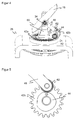
- FIG. 2 shows in a three-dimensional view of an embodiment of the coupling of rotational and tilting movement via a worm gear.
- the static part which is shown only as a solid base and is provided with the reference number of the drive 28 representative.
- the upper part of the here designed as a rotating mirror deflection unit 18 is shown, which is offset together with a mirror holder 60 by the running inside and therefore not visible shaft 40 in rotary motion.
- the worm gear includes a stationary worm 42a fixed to the static part with an inner bore for the shaft 40 and a gear 42b engaging the worm 42a and moving with the mirror holder 60.
- the profiled wheel 44 rotates on an axis with the gear 42b or is thus a common component and designed here as a cam.
- the guide element 48 rests with an impeller 62 on the circumference of the profiled wheel 44 and thus urges the deflector 18 depending on the radius of the profiled wheel 44 at the contact point in a defined tilt position with respect to the hinge point 34.
- the mirror holder 60 still has a balance weight 64 to balance the rotating mass with respect to the axis of rotation.
- FIG. 3 shows an enlarged detail of the coupling of profile wheel 44 and guide member 48 according to FIG. 2 .
- the profile wheel 44 is set in a rotational movement about an axis perpendicular to the axis of rotation of the deflection unit 18.
- the profile wheel 44 rotates slower, for example, only once every three or four revolutions of the deflector 18.
- the rotational movement of the deflector 18 superimposed on a correspondingly slowed tilting movement, which repeats only after several revolutions.
- the profile wheel 44 preferably has a plurality of circle segments, each with a constant radius. While the impeller 62 is running on such a part of the profiled wheel 44, so the tilt angle is kept constant and scanned a certain level. Between the circle segments are areas with positive or negative slope, which compensate between the respective constant radii and thereby set a new tilt angle. The tilting movement and thus also the overall movement of the deflection unit 18 can be kept very quiet by the respective strokes remain small in the adjustment. For example, four Abstastebenen be set with a tilt angle of 2.5 °.
- the scanning levels can be adjusted in an offset up and down stairs.
- the angles -7.5 °, -2.5 °, + 2.5 °, + 7.5 °, 5 °, 0 °, -5 ° are set in succession at seven scanning planes. In this way, a final return over the maximum tilt of 7.5 ° to -7.5 °, thus a total of 15 ° is avoided, and no stroke is greater than 5 °.
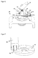
- FIG. 4 shows in a three-dimensional view, another embodiment of the coupling of rotational and tilting movement via a Torusgetriebe
- FIG. 5 is an associated enlargement of the coupling of profile wheel 44 and guide member 48 according to FIG. 4 ,
- like reference numerals designate the same or corresponding features.
- the fixed part of the transmission 42 is a Torusscale 42 a, which has a helical instead of a helical tooth course.
- the three-dimensional tooth course on a cylindrical surface of a screw is from above onto a circular surface of the torus disk bawled.
- a Torusgetriebe allows a lower height and a particularly quiet, closely coupled barrel.
- the two embodiments correspond according to FIGS. 2 and 3 or according to FIGS. 4 and 5 largely.
- the gear 42b also rotates in a Torusgetriebe about an axis perpendicular to the axis of rotation of the shaft 44, and the profiled wheel 44 is also a cam with all conceivable geometric configurations.
- FIG. 6 shows in a three-dimensional view of another embodiment of the coupling of rotational and tilting movement via a front gear
- FIG. 7 is an associated enlargement of the coupling of profile wheel 44 and guide member 48 according to FIG. 4 , Again, this embodiment largely corresponds to the earlier described embodiments.
- the transmission 42 is a spur gear with a first gear 42 a on the shaft 40, which in FIG. 6 is therefore not visible and the reference numeral only marks the position, and one with the first gear 42a in frontal engagement second gear 42b, which follows the movement of the deflection unit 18.
- the second gear 42b rotates about an axis parallel to the axis of rotation 30. Therefore, in this embodiment, the profile wheel 44 is preferably not formed as a cam, but as beidenprofilrad. This means that the profile is not arranged by different radii on the outer circumference, but as a height profile on a surface of the profile wheel. As in FIG. 7 easily recognizable, provides under the geometric conditions of this height profile for the desired up and down movement of the guide member 48.
- the height profile can be formed directly on the second gear 42b, so that no additional component is needed.
- FIG. 1 implement schematically shown inventive configuration.
- Other transmissions such as Maltese transmission in particular at slow rotational movement and thus low scanning frequency, are possible.
Landscapes
- Physics & Mathematics (AREA)
- Engineering & Computer Science (AREA)
- General Physics & Mathematics (AREA)
- Electromagnetism (AREA)
- Computer Networks & Wireless Communication (AREA)
- Radar, Positioning & Navigation (AREA)
- Remote Sensing (AREA)
- Optics & Photonics (AREA)
- Optical Radar Systems And Details Thereof (AREA)
- Geophysics And Detection Of Objects (AREA)
- Mechanical Optical Scanning Systems (AREA)
Description
- Die Erfindung betrifft einen optoelektronischen Sensor und ein Verfahren zur Erfassung von Objekten nach dem Oberbegriff von Anspruch 1 beziehungsweise 7.
- Scanner werden für vielfältige Überwachungs- und Vermessungsaufgaben verwendet. Dazu tastet ein Abtast- oder Scanstrahl einen Bereich ab und wertet das remittierte oder reflektierte Licht aus. Um auch Informationen über Objektabstände, Konturen oder Profile zu gewinnen, wird meist nicht nur die Anwesenheit von Objekten, sondern zugleich auch deren Entfernung bestimmt. Derartige entfernungsmessende Laserscanner arbeiten nach einem Lichtlaufzeitprinzip, bei dem die Laufzeit vom Scanner in die Szenerie und zurück gemessen wird und anhand der Lichtgeschwindigkeit Entfernungsdaten berechnet werden.
- Zwei Arten des Lichtlaufzeitverfahrens sind weit verbreitet. Bei phasenbasierten Verfahren moduliert der Lichtsender den Scanstrahl, und es wird die Phase zwischen einer Referenz und dem empfangenen Scanstrahl ermittelt. Pulsbasierte Verfahren prägen dem Scanstrahl ein signifikantes Muster auf, beispielsweise einen schmalen Puls von nur wenigen Nanosekunden Dauer und bestimmen den Empfangszeitpunkt dieses Musters. In einer als Pulsmittelungsverfahren bezeichneten Verallgemeinerung werden mehrere Pulse oder eine Pulsfolge ausgesandt und die empfangenen Pulse statistisch ausgewertet.
- Bekannte Laserscanner weisen einen Drehspiegel oder ein Polygonrad auf, um periodisch eine Überwachungsebene oder ein Segment einer Überwachungsebene abzutasten. Viele Anwendungen erfordern aber die Abtastung eines dreidimensionalen Raumbereichs und nicht lediglich einer Fläche. Ein herkömmlicher Ausweg besteht darin, für eine Relativbewegung zwischen Laserscanner und Objekt zu sorgen, wie beispielsweise in der
DE 197 41 730 B4 . Dies erfordert erheblichen Aufwand, und zahlreiche Anwendungen eignen sich gar nicht für eine solche kontrollierte Relativbewegung. - Um eine Bewegung des Laserscanners gegenüber dem zu vermessenden Objekt zu vermeiden, werden Laserscanner zu einem 3D-Scanner weitergebildet. Als Schritt hin zu einem 3D-Scanner kann eine Mehrebenenabtastung erreicht werden, indem Rasterspiegel mit unterschiedlich geneigten Facetten als Ablenkeinheit verwendet werden. Dadurch entsteht ein Winkelversatz der jeweils zu einer Facette gehörigen Abtastebene. Zugleich wird aber der Scanwinkelbereich der jeweiligen Abtastebene auf den Winkelanteil der Facette von typischerweise weniger als 100° beschränkt. Ein weiterer nachteiliger Effekt ist, dass nur die zentrale Scanebene wirklich eine Ebene ist, denn mit zunehmender Neigung der Facetten werden die Scanebenen aufbaubedingt unsymmetrisch verbogen. Besonders bei einer größeren Auffächerung der Scanebenen entstehen kaum brauchbare bogenförmige Scanlinien.
- Als weiterer Lösungsansatz ist bekannt, eine zusätzliche Ablenkeinheit meist in Form eines Schwingspiegels zu verwenden, der für eine Ablenkung des Scanstrahls in einer zweiten Richtung sorgt. Dadurch kann die Abtastebene verschwenkt werden. Durch die Verwendung zweier Ablenkeinheiten entstehen aber erhöhte Kosten und ein größerer Bauraumbedarf, somit ein hoher optischer und mechanischer Aufwand, zudem mit zusätzlichen Sende- und Empfangssignalverlusten. In einer speziellen Lösung mit zusätzlichem Schwingspiegel gemäß
DE 20 2009 012 114 U1 wird der 360°-Abtastbereich eines Drehspiegels aufgeteilt. In einem vorderen Winkelbereich wird in herkömmlicher Weise eine Fläche abgetastet. In einem hinteren Winkelbereich wird der Abtaststrahl mehrfach umgelenkt und fällt dann auf einen Schwingspiegel, der in einer Richtung quer zu der Ablenkrichtung des Drehspiegels verschwenkt wird. Somit wird über den hinteren Winkelbereich ein Raumausschnitt anstelle einer Fläche abgetastet. - Die Überwachung dreidimensionaler Abtastbereiche wird auch dadurch erreicht, dass der Drehspiegel und damit die Drehachse und die Abtastebene zusätzlich zu der Drehbewegung verkippt wird. In der
DE 10 2008 032 216 A1 beispielsweise wird die gesamte Scaneinheit samt Sender, Empfänger und Drehspiegel auf einem Ablenkteller angeordnet. Durch Verschwenken des Ablenktellers wird dann die Scanebene variiert, um so insgesamt einen dreidimensionalen Raumbereich zu überwachen. Dies erfordert aber erheblichen Zusatzaufwand für den Ablenkteller und den zusätzlichen Verschwenkantrieb. DieEP 1 965 225 A2 offenbart eine weitere Laserradarvorrichtung für die dreidimensionale Erfassung von Objekten, deren Ablenkeinheit durch eine Vielzahl vorgeschlagener Mechanismen zusätzlich verkippt wird. So verwenden einige Ausführungsformen für die Kippbewegung einen zweiten Antrieb zusätzlich zu dem Drehmotor, beispielsweise indem eine rotierende Kurvenscheibe in direkten Kontakt mit dem Drehspiegel gebracht wird. Dementsprechend muss aber der zweite Antrieb vorgesehen, angesteuert und synchronisiert werden. In einer anderen Ausführungsform sind zwei radial um 180 ° gegeneinander versetzt von der Ablenkeinheit nach außen stehende Drehglieder mit Rollen vorgesehen, die in einem Hohlprofil eines Führungspfads laufen. Dadurch wird der Drehbewegung eine Kippbewegung überlagert, die durch die Geometrie des Führungspfades erzwungen wird. Der vorgestellte Führungspfad ist aber ungeeignet, ein Abtastmuster über mehr als eine Umdrehung auszudehnen und beispielsweise einen Mehrebenenscanner auszubilden. - Die
US 6 373 612 B1 offenbart einen Laserscanner, dessen Spiegel in einen Mechanismus zur Variation der Kippstellung eingebaut ist. Dazu läuft ein Rädchen im Verlauf der Drehbewegung des Spiegels auf einem Höhenprofil in Form einer Dreieckswelle, und die Höhenunterschiede werden über eine Zahnstange auf die horizontale Achse des Spiegels und damit dessen Kippstellung übertragen. - In der
US 2005/0246065 A1 versetzt in einem Laserscanner ein Motor zwei konzentrische Zylinder jeweils in eine Drehbewegung, und zwar durch Zahnräder mit unterschiedlicher Drehgeschwindigkeit. Der äußere Zylinder trägt den Spiegel und einen Kipphebel mit einem Rädchen. Dieses Rädchen läuft auf einem Höhenprofil des inneren Zylinders, so dass über den Kipphebel der Kippwinkel des Spiegels variiert wird. Es ergibt sich eine räumliche Abtastkurve, die von den beiden Drehgeschwindigkeiten abhängt. - Die
JP S60 12527 A - Aus der
US 2010/0073749 A1 ist ein Scanner für eine mobile Vorrichtung bekannt, dessen Drehspiegel zugleich verkippt wird. Dazu ist ein erstes Zahnrad auf der vertikalen Achse des Antriebs für den Drehspiegel vorgesehen, das in Gewindeeingriff mit zwei weiteren Zahnrädern in senkrechter Anordnung zu dem ersten Zahnrad steht. Mit den weiteren Zahnrädern dreht sich auch eine senkrecht zu der vertikalen Achse stehende horizontale Achse, auf der wiederum zwei Kurvenscheiben mitrotieren. Sie sorgen durch ihre gegenläufig unterschiedlichen Radien für die gewünschte Kippbewegung eines Rahmens des Drehspiegels. - Vor diesem Hintergrund ist Aufgabe der Erfindung, die Erweiterung des Überwachungsbereichs eines optoelektronischen Sensors mit einfachen Mitteln zu ermöglichen.
- Diese Aufgabe wird durch einen optoelektronischen Sensor und ein Verfahren zur Erfassung von Objekten nach Anspruch 1 beziehungsweise 7 gelöst. Der erfindungsgemäße Sensor überwacht mehr als nur eine Abtastebene, indem dessen Ablenkeinheit zusätzlich zu ihrer Drehbewegung eine Kippbewegung vollzieht, welche die Drehachse und damit die Abtastebene variiert. Dadurch kann mit einfachen Mitteln ein Raumbereich überwacht werden, der größer ist als die durch reine Rotation der Ablenkeinheit entstehende Abtast- oder Scanebene. Die Erfindung geht von dem Grundgedanken aus, die Drehbewegung und die Kippbewegung durch ein Getriebe aneinander zu koppeln. Das Getriebe versetzt ein Profilrad in eine Drehbewegung, die aufgrund einer Untersetzung langsamer ist als diejenige der Ablenkeinheit. Ein Führungselement überträgt die Geometrie des Profils in eine Kippauslenkung der Ablenkeinheit. Aufgrund einer Untersetzung des Getriebes erstreckt sich die Kippbewegung über mehrere Drehungen der Ablenkeinheit, so dass über die Verkippung unterschiedliche Abtastebenen eingestellt werden. Vorzugsweise ist eine Feder oder ein ähnliches Element vorgesehen, um eine Gegenkraft auf das Führungselement auszuüben und dieses stets in engem Eingriff mit dem Profil zu halten. Auch andere Methoden zur spielfreien Führung sind denkbar.
- Eine Erfassung eines Objekts beinhaltet bei Laserscannern zumeist auch eine Positionsbestimmung durch Messen des Abstands mit einem der einleitend genannten Lichtlaufzeitverfahren, Bestimmen des Drehwinkels der Ablenkeinheit über einen Winkelencoder sowie des Kippwinkels anhand des Drehwinkels und dem bekannten winkelabhängigen Verlauf der Kippbewegung. Dadurch sind Radius und beide Winkel dreidimensionaler Kugelkoordinaten bestimmt.
- Die Erfindung hat den Vorteil, dass weder ein zusätzlicher Antrieb noch eine zusätzliche Ablenkeinheit erforderlich ist, um die Abtastebene zu variieren. Dadurch können Herstellkosten, Baugröße, mechanische Anfälligkeit und Stromaufnahme reduziert werden. Die Vorgabe der Verkippung ermöglicht dabei eine Anpassung der Abtastung an die jeweilige Anwendung. Das Getriebe und das Profilrad sorgen für eine .verlässliche, harmonische Kippbewegung, und die Erzeugung der Kippbewegung ist zugleich robust und wartungsarm gelöst.
- Das Profilrad ist in einer beanspruchten Alternative als Kurvenscheibe ausgebildet. Das Führungselement läuft dabei an dessen Außenumfang und überträgt damit die verschiedenen Radien der Kurvenscheibe in entsprechende Kippwinkel der Ablenkeinheit. Die Geometrie der Kurvenscheibe gibt so auf sehr einfache Weise eine gewünschte Kippbewegung und damit ein Abtastmuster vor.
- Die Kurvenscheibe weist dazu mehrere Segmente mit jeweils konstantem, aber zwischen den Segmenten unterschiedlichem Radius sowie Verstellbereichen dazwischen auf. In den Bereichen mit konstantem Radius, die also Kreisbögen bilden, ändert sich der Kippwinkel nicht. Jedes Segment legt damit über den Radius eine Abtastebene fest, die zueinander entsprechend der Unterschiede in den Radien zwischen den Segmenten beabstandet sind. So entsteht ein Mehrebenenscanner. Die Verstellbereiche gleichen die unterschiedlichen Radien von Segment zu Segment durch entsprechende Anstiege oder Gefälle aus, und zwar nach Möglichkeit so, dass sich eine glatte Gesamtkontur und damit ruhige Kippbewegung ergibt. Alternativ zu der beanspruchten Ausgestaltung kann die Kurvenscheibe aber auch eine beliebige Geometrie etwa mit ständig veränderten Radien aufweisen, so dass die Verkippung kontinuierlich variiert und es keine Abtastebene im eigentlichen Sinne mehr gibt, sondern nur noch einen von dem Abtaststrahl durch die Überlagerung der Drehbewegung und der Verkippung erfassten Raumbereich.
- Das Profilrad ist in einer anderen beanspruchten Ausführungsform als Höhenprofilrad ausgebildet. Hier läuft das Führungselement nicht wie bei einer Kurvenscheibe am Außenumfang, sondern auf der Radfläche. Diese Radfläche ist nicht eben, sondern weist ein Höhenprofil entsprechend der gewünschten Kippbewegung auf. Hinsichtlich der möglichen Ausgestaltungen des Höhenprofilrads gilt das gleiche wie für eine Kurvenscheibe. Entsprechend ist auch das Profil des Höhenprofilrads in Bereiche jeweils gleicher Höhe segmentiert sein, wobei diese Höhe von Segment zu Segment variiert, um einen Mehrebenenscanner zu realisieren. Zwischen den Segmenten befinden sich dann Anstiege oder Gefälle als Übergangsbereiche, in denen das Führungselement die Höhe wechselt. Dabei findet nur Rollreibung statt, und die Mechanik wird besonders verschleißunanfällig.
- Das Getriebe ist bevorzugt als Schneckengetriebe mit einer um die Drehachse angeordneten feststehenden Schnecke und einem seitlich in die Schnecke eingreifenden Zahnrad der Kippeinheit ausgebildet. Die Schnecke sorgt praktisch dafür, dass die Welle einen helixartigen Zahnverlauf aufweist, in welchen das Zahnrad von der Seite her eingreift. Das Zahnrad dreht sich dann vorzugsweise auf einer Achse mit dem Profilrad.
- Alternativ ist das Getriebe als Torusgetriebe mit einem senkrecht zu der Drehachse angeordneten feststehenden Torusrad, das auf einer Radfläche einen spiralförmigen Zahnverlauf aufweist, und einem senkrecht zu dem Torusrad in den Zahnverlauf eingreifenden Zahnrad der Kippeinheit ausgebildet. Statt einer Helix auf einem Zylindermantel um die Antriebswelle bildet hier der Zahnverlauf eine Spirale auf einer Kreisfläche. Von oben her greift das Zahnrad in den Zahnverlauf ein und wird darin gleitend zum Drehen gebracht. Das Torusgetriebe ist besonders kompakt, wartungsarm und laufruhig.
- Das Profilrad ist in beiden Fällen bevorzugt als Kurvenscheibe ausgebildet und rotiert auf einer Achse mit dem Zahnrad. Schneckengetriebe wie Torusgetriebe übertragen nämlich die Drehbewegung auf eine um 90° verkippte Drehachse, und genau eine in dieser Orientierung rotierende Kurvenscheibe ist geeignet, die Ablenkeinheit über ein gerades Führungselement zu verkippen.
- In einer weiteren Alternative ist das Getriebe als Stirngetriebe mit einem um die Drehachse angeordneten feststehenden ersten Zahnrad und einem daneben angeordneten zweiten Zahnrad ausgebildet, das durch Eingriff in das erste Zahnrad um eine Achse parallel zu der Drehachse rotiert. Ein solches Getriebe ist besonders einfach.
- In diesem Fall ist das Profilrad bevorzugt als Höhenprofilrad ausgebildet und rotiert auf einer Achse mit dem zweiten Zahnrad. Das Stirngetriebe überträgt die Drehbewegung auf eine parallele statt einer um 90° verkippten Drehachse, und deshalb eignet sich hier nicht eine Kurvenscheibe, sondern ein Höhenprofilrad dazu, über ein gerades Führungselement die Drehbewegung des Profilrads in eine Kippbewegung der Ablenkeinheit zu übersetzen. Das Höhenprofil kann unmittelbar auf dem zweiten Zahnrad vorgegeben werden. Diese einstückige Ausführung ermöglicht den Verzicht auf ein Bauteil.
- Das erfindungsgemäße Verfahren kann auf ähnliche Weise weitergebildet werden und zeigt dabei ähnliche Vorteile. Derartige vorteilhafte Merkmale sind beispielhaft, aber nicht abschließend in den sich an die unabhängigen Ansprüche anschließenden Unteransprüchen beschrieben.
- Die Erfindung wird nachstehend auch hinsichtlich weiterer Merkmale und Vorteile beispielhaft anhand von Ausführungsformen und unter Bezug auf die beigefügte Zeichnung näher erläutert. Die Abbildungen der Zeichnung zeigen in:
- Fig. 1
- eine Schnittdarstellung eines Laserscanners mit einem untersetzten Getriebe zum Verkippen der Ablenkeinheit mit der Drehbewegung;
- Fig. 2
- eine dreidimensionale Ansicht einer Ausführungsform der Kopplung von Dreh- und Kippbewegung über ein Schneckengetriebe;
- Fig. 3
- eine Ausschnittvergrößerung der
Figur 2 des Eingriffs eines Führungselemente der Ablenkeinheit und einer durch das Schneckengetriebe an die Drehbewegung angekoppelten Kurvenscheibe; - Fig. 4
- eine dreidimensionale Ansicht einer Ausführungsform der Kopplung von Dreh- und Kippbewegung über ein Torusgetriebe;
- Fig. 5
- eine Ausschnittvergrößerung der
Figur 4 des Eingriffs eines Führungselemente der Ablenkeinheit und eines durch das Torusgetriebe an die Drehbewegung angekoppelten Höhenprofilrades; - Fig. 6
- eine dreidimensionale Ansicht einer Ausführungsform der Kopplung von Dreh- und Kippbewegung über ein Stirngetriebe; und
- Fig. 7
- eine Ausschnittvergrößerung der
Figur 6 des Eingriffs eines Führungselemente der Ablenkeinheit und einer durch das Stirngetriebe an die Drehbewegung angekoppelten Kurvenscheibe. -
Figur 1 zeigt eine Schnittdarstellung eines Laserscanners 10. Es sind diverse andere Anordnungen der einzelnen Elemente eines optoelektronischen Sensors zur Erfassung von Objekten denkbar und von der Erfindung umfasst. Insbesondere gibt es eine Vielzahl bekannter Varianten von Laserscannern, aus denen jeweils durch entsprechende Abwandlung erfindungsgemäße Laserscanner entstehen können. Die Darstellung soll also nur beispielhaft zu verstehen sein. - Ein Lichtsender 12, beispielsweise eine LED oder eine Laserdiode, sendet über eine Sendeoptik 14 einen Sendelichtstrahl oder Abtaststrahl 16 aus, der nach Ablenkung an einer Ablenkeinheit 18 aus dem Laserscanner 10 in einen Überwachungsbereich 20 austritt. Wird von dem Sendelichtstrahl 16 ein Objekt angetastet, so kehrt reflektiertes oder remittiertes Licht 22 zu dem Laserscanner 10 zurück und wird nach erneuter Ablenkung an der Ablenkeinheit 18 von einer Empfangsoptik 24 auf einen Lichtempfänger 26 gebündelt. Es ist denkbar, eine Kanaltrennung zwischen Sendepfad und Empfangspfad etwa durch einen drehfest mit der Ablenkeinheit verbundenen, nicht dargestellten Tubus um den Sendelichtstrahl 16 vorzunehmen.
- Ein Antrieb 28 versetzt die Ablenkeinheit 18 in eine Drehbewegung bezüglich einer Drehachse 30. Die jeweilige Winkelstellung wird von einem Encoder bestimmt, der beispielsweise eine Gabellichtschranke 32a und eine Strichscheibe 32b aufweist. Im Verlauf der Drehbewegung würde der Abtaststrahl 16 bei konstantem Kippwinkel zwischen Ablenkeinheit 18 und Drehachse 30 eine zu der Drehachse 30 senkrechte Abtastebene periodisch abtasten.
- Die Ablenkeinheit 18 ist aber an einem Gelenkpunkt 34 wie durch einen Pfeil 36 angedeutet verkippbar gelagert, was zu einer durch einen Pfeil 38 angedeuteten Winkelabweichung des Abtaststrahls 16 führt. Somit wird anstelle einer einfachen Abtastebene ein Raumbereich mit einer Abtastkurve erfasst, die von der überlagerten Dreh- und Kippbewegung abhängt.
- Die Verkippung der Ablenkeinheit 18 wird ebenso wie die Drehbewegung vom gleichen Antrieb 28 bewirkt. Dazu wird die Drehbewegung einer Welle 40 des Antriebs 28 über ein untersetztes Getriebe 42 auf ein Profilrad 44 übertragen. Das Profilrad 44 dreht sich also wie durch einen Pfeil 46 angedeutet mit der Welle 40, jedoch entsprechend der Untersetzung langsamer. Die Drehachse des Profilrads 44 hängt von der Art des Getriebes 42 ab und kann beispielsweise senkrecht oder parallel zu der Drehachse 30 der Welle 40 liegen. Das Profilrad 44 weist eine namensgebende profilierte Geometrie auf, die dafür sorgt, dass sich ein mit dem Profil des Profilrads 44 in Eingriff stehendes Führungselement 48 wie durch einen Pfeil 50 gezeigt mit der Drehung des Profilrads 44 auf und ab bewegt. Das Führungselement 48 steht andererseits mit der Ablenkeinheit 18 in Eingriff oder ist mit ihr verbunden und bewirkt so entsprechend seiner Aufund Abwärtsbewegung die Kippbewegung der Ablenkeinheit 18.
- Auf diese Weise genügt ein gemeinsamer Aktor für sowohl die Dreh- als auch die Kippbewegung der Ablenkeinheit 18. Das ist wesentlich kompakter und kostengünstiger als ein prinzipiell denkbarer eigener Antrieb für das Profilrad 44. Dabei zeigt
Figur 1 Getriebe 42, Profilrad 44 und Führungselement 48 nur rein schematisch. Weiter unten werden im Zusammenhang mit denFiguren 2 bis 7 verschiedene Beispiele vorgestellt, wie dies mit konkreten mechanischen Elementen erreicht werden kann. - Die Kippbewegung ermöglicht verschiedenste Abtastmuster. In einer bevorzugten Ausführung als Mehrebenenscanner sorgt die Kippbewegung für Wechsel der Abtastebene, jeweils gefolgt von einem Intervall ohne Kippbewegung, um eine dem eingestellten Kippwinkel entsprechende Ebene abzutasten. Das Profilrad 44 wird mit jeder Umdrehung der Welle 40 entsprechend der Untersetzung des Getriebes 42 weitergedreht. Für einen 4-Lagen-Scanner beispielsweise wäre eine Untersetzung von 4:1 zu wählen. Damit dreht sich das Profilrad 44 mit jeder Umdrehung der Welle 40 um 90° weiter. Das Profil ist so ausgebildet, dass über einen Großteil dieser 90° der jeweilige Kippwinkel konstant bleibt, während der verbleibende kleinere Teil den neuen Kippwinkel für die nächste Ebene einstellt. Nach vier Umdrehungen der Welle 40 hat sich auch das Profilrad 44 einmal vollständig gedreht, und das Abtastmuster wiederholt sich.
- Bei einem solchen Mehrebenenscanner gehört der Winkelbereich der Drehbewegung, in dem ein neuer Kippwinkel eingestellt wird, zu keiner Abtastebene. Andererseits haben die meisten Laserscanner ohnehin keine 360°-Erfassung, sondern einen gewissen Totbereich. Vorzugsweise wird dann der Verstellbereich des Kippwinkels in den Totbereich gelegt. So sind Abtastungen in allen Ebenen mit Scanwinkeln von 300° und mehr erreichbar. Je nach Anwendung kann der Verstellbereich auch messtechnisch genutzt und damit eine 360°-Erfassung erreicht werden.
- Die Kippbewegung ist selbstverständlich nicht auf dieses Beispiel beschränkt. Zunächst einmal lassen sich durch eine andere Untersetzung des Getriebes 42 und ein anderes Profil des Profilrads 44 wenige bis sehr viele Abtastebenen anstelle von vier Abtastebenen realisieren. Allgemein sind je nach Anforderung der Anwendung nahezu beliebige Raummuster erreichbar, etwa um gerade Scanlinien auf einer ebenen Wand zu erreichen, einen Doppelkegel helixartig abzutasten und dergleichen.
- Durch die kontinuierliche Dreh- und Kippbewegung, die sich auch nach einer vollständigen Umdrehung des Profilrads 44 ohne besonderen Rücklauf mit einer Wiederholung fortsetzt, ergibt sich ein harmonischer, ruhiger Lauf von großer Lebensdauer. Alle Reibbewegungen können lediglich abrollend mit robusten, laufruhigen Bauteilen wie Kugellagern ausgelegt werden, beziehungsweise Kippbewegungen mittels Blattfedern. Die Kopplungen, etwa diejenige zwischen Ablenkeinheit 18, Führungselement 48 und Profilrad 44, können vorzugsweise jeweils durch Federn oder ähnliche Elemente spielfrei gehalten werden.
- Bevor nun einige konkretisierte Ausführungsbeispiele erläutert werden, soll noch die Beschreibung des Laserscanners 10 gemäß
Figur 1 abgeschlossen werden. Eine Steuer- und Auswertungseinheit 52 ist mit dem Lichtsender 12 und dem Lichtempfänger 26 verbunden, um den Sendelichtstrahl 16 zu erzeugen und ein aus remittiertem Licht 22 in dem Lichtempfänger 26 erzeugtes Empfangssignal auszuwerten. Bei dieser Auswertung wird festgestellt, ob ein Objekt erfasst wurde. Die Steuer- und Auswertungseinheit 52 steuert außerdem den Antrieb 28 und erhält das Winkelsignal des Encoders 32a-b. - Vorzugsweise nimmt die Steuer- und Auswertungseinheit 52 mit der Erfassung der Objekte auch eine Positionsbestimmung vor. Dazu werden die drei Kugelkoordinaten bestimmt. Der Abstand wird mit einem der einleitend genannten Lichtlaufzeitverfahren gemessen. Der erste Winkel bezüglich der Drehbewegung für die Erfassung eines Objekts ist von dem Encoder 32a-b unmittelbar bekannt. Den zweiten Winkel bestimmt die Steuer- und Auswertungseinheit 52 als den Kippwinkel. Der jeweils zu einer Drehstellung des Profilrads 44 gehörige Kippwinkel wird dazu 44 parametriert oder eingelernt. Da die aktuelle Drehstellung des Profilrads 44 über das Getriebe 42 direkt mit der von dem Encoder 32a-b bestimmten Drehstellung der Welle 40 zusammenhängt, kennt die Steuer- und Auswertungseinheit 52 dann auch den zweiten Winkel. Wegen der Untersetzung des Getriebes 42 muss dabei die Drehstellung der Welle 40 über mehr als eine Drehung, also beispielsweise bei einer Untersetzung von 4:1 wie für einen 4-Lagen-Scanner über 4*360°=1440° erfasst werden. Es ist aber auch denkbar, die Drehstellung des Profilrads 44 oder die Kippstellung der Ablenkeinheit 18 mit weiteren Sensoren beziehungsweise über den Sendestrahl 16 zu bestimmen.
- Das gewünschte Ergebnis der Auswertung wird an einem Ausgang 54 bereitgestellt, sei es beispielsweise als binäres Objektfeststellungssignal insbesondere für sicherheitstechnische Anwendungen, als Objektliste mit Koordinaten der Erfassung oder als zwei- beziehungsweise dreidimensionales Rohbild.
- Der Laserscanner 10 wird von einem Gehäuse 56 geschützt, das im Aus- und Eintrittsbereich der Lichtstrahlen 16, 22 eine Frontscheibe 58 aufweist, die für die jeweilige Wellenlänge transparent ist, also beispielsweise für sichtbares, infrarotes und/oder ultraviolettes Licht.
-
Figur 2 zeigt in einer dreidimensionalen Ansicht eine Ausführungsform der Kopplung von Dreh- und Kippbewegung über ein Schneckengetriebe. Im unteren Teil befindet sich der statische Teil, der nur als fester Sockel gezeigt und stellvertretend mit dem Bezugszeichen des Antriebs 28 versehen ist. Im oberen Teil ist die hier als Drehspiegel ausgebildete Ablenkeinheit 18 gezeigt, die samt einem Spiegelhalter 60 durch die im Inneren verlaufende und daher nicht sichtbare Welle 40 in Drehbewegung versetzt wird. Das Schneckengetriebe umfasst eine ruhende, am statischen Teil fixierte Schnecke 42a mit einer inneren Bohrung für die Welle 40 und ein in die Schnecke 42a eingreifendes, mit dem Spiegelhalter 60 mitbewegtes Zahnrad 42b. Das Profilrad 44 dreht sich auf einer Achse mit dem Zahnrad 42b oder ist damit ein gemeinsames Bauteil und hier als Kurvenscheibe ausgebildet. Das Führungselement 48 liegt mit einem Laufrad 62 auf dem Umfang des Profilrads 44 auf und drängt somit die Ablenkeinheit 18 je nach Radius des Profilrads 44 an der Berührungsstelle in eine definierte Kippposition bezüglich dem Gelenkpunkt 34. Gegenüber dem Zahnrad 42b weist der Spiegelhalter 60 noch ein Wuchtgewicht 64 auf, um die rotierende Masse bezüglich der Drehachse auszubalancieren. -
Figur 3 zeigt eine Ausschnittvergrößerung der Kopplung von Profilrad 44 und Führungselement 48 gemäßFigur 2 . Durch den Eingriff des Zahnrads 42b in die Schnecke 42a wird das Profilrad 44 in eine Drehbewegung um eine Achse senkrecht zur Drehachse der Ablenkeinheit 18 versetzt. Entsprechend der Untersetzung des Getriebes dreht sich das Profilrad 44 langsamer, beispielsweise nur einmal je drei oder vier Umdrehungen der Ablenkeinheit 18. Dadurch überlagert sich der Drehbewegung der Ablenkeinheit 18 eine entsprechend verlangsamte Kippbewegung, die sich erst nach mehreren Umdrehungen wiederholt. - Das Profilrad 44 weist bevorzugt mehrere Kreissegmente mit jeweils konstantem Radius auf. Während das Laufrad 62 auf einem solchen Teil des Profilrads 44 abläuft, wird so der Kippwinkel konstant gehalten und eine bestimmte Ebene abgetastet. Zwischen den Kreissegmenten befinden sich Bereiche mit positiver oder negativer Steigung, welche zwischen den jeweiligen konstanten Radien ausgleichen und dadurch einen neuen Kippwinkel einstellen. Die Kippbewegung und damit auch die Gesamtbewegung der Ablenkeinheit 18 kann sehr ruhig gehalten werden, indem die jeweiligen Hübe in den Verstellbereichen klein bleiben. Beispielsweise werden vier Abstastebenen mit einem Kippwinkel von jeweils 2,5° eingestellt.
- Um den Kippwinkel auch im Rücklauf klein zu halten, können die Abtastebenen in einer versetzten Auf- und Abwärtstreppe eingestellt werden. Dazu werden beispielsweise bei sieben Abtastebenen nacheinander die Winkel -7,5 °, -2,5°, +2,5°, +7,5°, 5°, 0°, -5° eingestellt. Auf diese Weise wird ein abschließender Rücklauf über die maximale Verkippung von 7,5° zu -7,5°, also insgesamt 15° vermieden, und kein Hub ist größer als 5°.
-
Figur 4 zeigt in einer dreidimensionalen Ansicht eine weitere Ausführungsform der Kopplung von Dreh- und Kippbewegung über ein Torusgetriebe, undFigur 5 ist eine zugehörige Ausschnittvergrößerung der Kopplung von Profilrad 44 und Führungselement 48 gemäßFigur 4 . Wie in der gesamten Beschreibung, bezeichnen gleiche Bezugszeichen die gleichen oder einander entsprechenden Merkmale. - Im Unterschied zu der Ausführungsform gemäß
Figuren 2 und 3 ist hier der fixe Teil des Getriebes 42 eine Torusscheibe 42a, die einen spiralförmigen statt eines helixartigen Zahnverlauf aufweist. Im Prinzip ist der dreidimensionale Zahnverlauf auf einem Zylindermantel einer Schnecke von oben her auf eine Kreisfläche der Torusscheibe zusammengestaucht. Ein Torusgetriebe ermöglicht eine geringere Bauhöhe und einen besonders ruhigen, eng gekoppelten Lauf. Von den unterschiedlichen Getrieben abgesehen, entsprechen sich die beiden Ausführungsformen gemäßFiguren 2 und 3 beziehungsweise gemäßFiguren 4 und 5 weitgehend. Insbesondere dreht sich das Zahnrad 42b auch bei einem Torusgetriebe um eine Achse senkrecht zu der Drehachse der Welle 44, und das Profilrad 44 ist ebenfalls eine Kurvenscheibe mit allen dazu denkbaren geometrischen Ausgestaltungen. -
Figur 6 zeigt in einer dreidimensionalen Ansicht eine weitere Ausführungsform der Kopplung von Dreh- und Kippbewegung über ein Stirngetriebe, undFigur 7 ist eine zugehörige Ausschnittvergrößerung der Kopplung von Profilrad 44 und Führungselement 48 gemäßFigur 4 . Erneut entspricht diese Ausführungsform weitgehend den früher beschriebenen Ausführungsformen. - Das Getriebe 42 ist aber in diesem Fall ein Stirngetriebe mit einem ersten Zahnrad 42a auf der Welle 40, das in
Figur 6 innen liegt, daher nicht erkennbar ist und dessen Bezugszeichen nur die Position markiert, und einem mit dem ersten Zahnrad 42a in Stirneingriff stehenden zweiten Zahnrad 42b, das die Bewegung der Ablenkeinheit 18 mitvollzieht. Aufgrund des Stirneingriffs rotiert das zweite Zahnrad 42b um eine Achse parallel zu der Drehachse 30. Deshalb ist in dieser Ausführungsform das Profilrad 44 vorzugsweise nicht als Kurvenscheibe, sondern als Höhenprofilrad ausgebildet. Das bedeutet, dass das Profil nicht durch unterschiedliche Radien am Außenumfang, sondern als Höhenprofil auf einer Fläche des Profilrads angeordnet ist. Wie inFigur 7 leicht erkennbar, sorgt unter den geometrischen Gegebenheiten dieses Höhenprofil für die gewünschte Auf- und Abbewegung des Führungselements 48. Das Höhenprofil kann unmittelbar auf dem zweiten Zahnrad 42b ausgebildet sein, so dass kein zusätzliches Bauteil benötigt wird. - Wie die drei Beispiele eines Schneckengetriebes, Torusgetriebes und Stirngetriebes zeigen mit Kurvenscheibe oder Höhenprofilrad, gibt es zahlreiche Möglichkeiten, die in
Figur 1 schematisch gezeigte erfindungsgemäße Konfiguration umzusetzen. Auch andere Getriebe, wie etwa Maltesergetriebe insbesondere bei langsamer Drehbewegung und damit geringer Scanfrequenz, sind möglich.
Claims (7)
- Optoelektronischer Sensor (10), insbesondere Laserscanner, zur Erfassung von Objekten in einem Überwachungsbereich (20) mit mehr als einer Abtastebene, der einen Lichtsender (12) zum Aussenden eines Lichtstrahls (16), einen Antrieb (28) zum Erzeugen einer Drehbewegung, eine von dem Antrieb (28) um eine Drehachse (30) drehbare Ablenkeinheit (18) zur periodischen Ablenkung des Lichtstrahls (16), eine an den Antrieb (28) gekoppelte Kippeinheit (42b, 44) zum Verkippen der Ablenkeinheit (18) mit der Drehbewegung, einen Lichtempfänger (26) zum Erzeugen eines Empfangssignals aus dem in dem Überwachungsbereich remittierten oder reflektierten Lichtstrahl (22) sowie eine Auswertungseinheit (52) aufweist, welche für die Erfassung der Objekte anhand des Empfangssignals ausgebildet ist,
wobei die Kippeinheit (42b, 44) ein Profilrad (44) aufweist, dessen Profil mit einem Führungselement (48) der Ablenkeinheit (18) in Eingriff steht und so die Kippbewegung erzeugt und wobei das Profilrad (44) durch ein Getriebe (42) an den Antrieb (28) angekoppelt ist, um so die Drehbewegung des Antriebs (28) mit einer Untersetzung mitzuvollziehen,
dadurch gekennzeichnet,
dass das Profilrad (44) als Kurvenscheibe, die mehrere Segmente mit jeweils konstantem, aber zwischen den Segmenten unterschiedlichem Radius sowie Verstellbereichen dazwischen aufweist, oder als Höhenprofilrad ausgebildet ist, das in Bereiche jeweils gleicher Höhe segmentiert ist, wobei diese Höhe von Segment zu Segment variiert. - Sensor (10) nach Anspruch 1,
wobei das Getriebe (44) als Schneckengetriebe mit einer um die Drehachse (30) angeordneten feststehenden Schnecke (42a) und einem seitlich in die Schnecke (42a) eingreifenden Zahnrad (42b) der Kippeinheit (42b, 44) ausgebildet ist. - Sensor (10) nach Anspruch 1,
wobei das Getriebe (42) als Torusgetriebe mit einem senkrecht zu der Drehachse (30) angeordneten feststehenden Torusrad (42a), das auf einer Radfläche einen spiralförmigen Zahnverlauf aufweist, und einem senkrecht zu dem Torusrad (42a) in den Zahnverlauf eingreifenden Zahnrad (42b) der Kippeinheit (42b, 44) ausgebildet ist. - Sensor (10) nach Anspruch 2 oder 3,
wobei das Profilrad (44) als Kurvenscheibe ausgebildet ist und auf einer Achse mit dem Zahnrad (42b) rotiert. - Sensor (10) nach Anspruch 1,
wobei das Getriebe (42) als Stirngetriebe mit einem um die Drehachse (30) angeordneten feststehenden ersten Zahnrad (42a) und einem daneben angeordneten zweiten Zahnrad (42b) ausgebildet ist, das durch Eingriff in das erste Zahnrad (42a) um eine Achse parallel zu der Drehachse (30) rotiert. - Sensor (10) nach Anspruch 5,
wobei das Profilrad (44) als Höhenprofilrad ausgebildet ist und auf einer Achse mit dem zweiten Zahnrad (42b) rotiert, insbesondere das Höhenprofilrad und das zweite Zahnrad (42b) einstückig ausgebildet sind. - Verfahren zur Erfassung von Objekten in einem Überwachungsbereich (20) mit mehr als einer Abtastebene, bei dem ein Lichtstrahl (16) ausgesandt und aus dem in dem Überwachungsbereich (20) remittierten oder reflektierten Lichtstrahl (22) ein Empfangssignal erzeugt und ausgewertet wird, um die Objekte zu erfassen, wobei der Lichtstrahl (16) den Überwachungsbereich (20) mittels einer Ablenkeinheit (18) periodisch abtastet, die durch einen Antrieb (28) in Drehbewegung versetzt und zugleich mit einer an den Antrieb (28) gekoppelten Kippeinheit (42b, 44) verkippt wird, wobei die Drehbewegung das Verkippen dadurch bewirkt, dass ein Profilrad (44) der Kippeinheit (42b, 44) mit einem Führungselement (48) der Ablenkeinheit (18) in Eingriff steht, und wobei das Profilrad (44) durch Ankopplung an den Antrieb (28) über ein Getriebe (42) die Drehbewegung des Antriebs (28) mit einer Untersetzung mitvollzieht dadurch gekennzeichnet,
dass mehrere Abtastebenen abgetastet werden, indem das Profilrad (44) als Kurvenscheibe, die mehrere Segmente mit jeweils konstantem, aber zwischen den Segmenten unterschiedlichem Radius sowie Verstellbereichen dazwischen aufweist, oder als Höhenprofilrad ausgebildet ist, das in Bereiche jeweils gleicher Höhe segmentiert ist, wobei diese Höhe von Segment zu Segment variiert.
Applications Claiming Priority (1)
| Application Number | Priority Date | Filing Date | Title |
|---|---|---|---|
| DE102014102049.9A DE102014102049B4 (de) | 2014-02-18 | 2014-02-18 | Optoelektronischer Sensor und Verfahren zur Erfassung von Objekten in einem Überwachungsbereich |
Publications (2)
| Publication Number | Publication Date |
|---|---|
| EP2908152A1 EP2908152A1 (de) | 2015-08-19 |
| EP2908152B1 true EP2908152B1 (de) | 2016-06-08 |
Family
ID=52023383
Family Applications (1)
| Application Number | Title | Priority Date | Filing Date |
|---|---|---|---|
| EP14198082.1A Active EP2908152B1 (de) | 2014-02-18 | 2014-12-16 | Optoelektronischer Sensor und Verfahren zur Erfassung von Objekten in einem Überwachungsbereich |
Country Status (3)
| Country | Link |
|---|---|
| EP (1) | EP2908152B1 (de) |
| JP (1) | JP6028050B2 (de) |
| DE (1) | DE102014102049B4 (de) |
Cited By (1)
| Publication number | Priority date | Publication date | Assignee | Title |
|---|---|---|---|---|
| EP4060374A1 (de) | 2021-03-15 | 2022-09-21 | Sick Ag | Erfassung eines objekts in einem überwachungsbereich |
Families Citing this family (3)
| Publication number | Priority date | Publication date | Assignee | Title |
|---|---|---|---|---|
| BR112018076410A2 (pt) | 2016-06-24 | 2019-04-09 | 3Shape A/S | escâner 3d usando um feixe de luz de sonda estruturado |
| CN107942337A (zh) * | 2016-10-13 | 2018-04-20 | 北京飞思迈尔光电科技有限公司 | 一种光学扫描传感器 |
| EP3955022A1 (de) * | 2020-08-12 | 2022-02-16 | Leuze electronic GmbH + Co. KG | Sensoranordnung und verfahren zu deren betrieb |
Family Cites Families (15)
| Publication number | Priority date | Publication date | Assignee | Title |
|---|---|---|---|---|
| JPS514862B2 (de) * | 1971-09-16 | 1976-02-16 | ||
| DE3128350A1 (de) * | 1981-07-17 | 1983-02-03 | Siemens AG, 1000 Berlin und 8000 München | Einrichtung zum abgriff einer kurvenscheibe, insbesondere fuer optisch-mechanische abtastsysteme |
| JPS6012527A (ja) * | 1983-07-04 | 1985-01-22 | Secoh Giken Inc | 赤外ビ−ム走査装置 |
| US6034803A (en) * | 1997-04-30 | 2000-03-07 | K2 T, Inc. | Method and apparatus for directing energy based range detection sensor |
| DE19741730B4 (de) | 1997-09-22 | 2006-02-02 | Sick Ag | Verfahren zur Ermittlung der Oberflächenkontur von Meßobjekten |
| CA2505715A1 (en) * | 2004-05-03 | 2005-11-03 | Her Majesty In Right Of Canada As Represented By The Minister Of National Defence | Volumetric sensor for mobile robotics |
| US7880865B2 (en) | 2007-02-28 | 2011-02-01 | Denso Wave Incorporated | Laser radar apparatus for three-dimensional detection of objects |
| JP5266739B2 (ja) * | 2007-02-28 | 2013-08-21 | 株式会社デンソーウェーブ | レーザレーダ装置 |
| JP2008224623A (ja) * | 2007-03-15 | 2008-09-25 | Victor Co Of Japan Ltd | 測定装置 |
| DE102008032216A1 (de) | 2008-07-09 | 2010-01-14 | Sick Ag | Vorrichtung zur Erkennung der Anwesenheit eines Objekts im Raum |
| KR101046040B1 (ko) * | 2008-09-23 | 2011-07-01 | 삼성전기주식회사 | 자율주행체의 공간 스캔 장치 |
| DE202009012114U1 (de) | 2009-09-05 | 2011-02-03 | Sick Ag | Optoelektronischer Scanner |
| EP2549290A1 (de) * | 2011-07-18 | 2013-01-23 | Sick Ag | Optoelektronischer Sensor und Verfahren zur Erfassung und Abstandsbestimmung von Objekten |
| DE202011110290U1 (de) * | 2011-07-18 | 2013-04-30 | Sick Ag | Optoelektronischer Sensor |
| WO2014010107A1 (ja) * | 2012-07-11 | 2014-01-16 | 北陽電機株式会社 | 走査式測距装置 |
-
2014
- 2014-02-18 DE DE102014102049.9A patent/DE102014102049B4/de not_active Expired - Fee Related
- 2014-12-16 EP EP14198082.1A patent/EP2908152B1/de active Active
-
2015
- 2015-01-30 JP JP2015016536A patent/JP6028050B2/ja active Active
Non-Patent Citations (1)
| Title |
|---|
| None * |
Cited By (1)
| Publication number | Priority date | Publication date | Assignee | Title |
|---|---|---|---|---|
| EP4060374A1 (de) | 2021-03-15 | 2022-09-21 | Sick Ag | Erfassung eines objekts in einem überwachungsbereich |
Also Published As
| Publication number | Publication date |
|---|---|
| JP2015152926A (ja) | 2015-08-24 |
| DE102014102049B4 (de) | 2016-03-24 |
| JP6028050B2 (ja) | 2016-11-16 |
| DE102014102049A1 (de) | 2015-08-20 |
| EP2908152A1 (de) | 2015-08-19 |
Similar Documents
| Publication | Publication Date | Title |
|---|---|---|
| EP2746808B1 (de) | Optoelektronischer Sensor zur Erfassung von Objekten | |
| EP3486833B1 (de) | Polygonscanner und verfahren zum erfassen von objekten in einem überwachungsbereich | |
| DE102014100245B3 (de) | Optoelektronischer Sensor und Verfahren zur Erfassung von Objekten in einem Überwachungsbereich | |
| EP2908152B1 (de) | Optoelektronischer Sensor und Verfahren zur Erfassung von Objekten in einem Überwachungsbereich | |
| EP2296002B1 (de) | Optoelektronischer Scanner zur Abstandsbestimmung in Azimut- und Elevationsrichtung | |
| EP2983030B1 (de) | Mehrebenenscanner und verfahren zum erfassen von objekten | |
| EP3388865B1 (de) | Optoelektronischer sensor und verfahren zur erfassung eines objekts | |
| EP2667218B1 (de) | Energiespar-3-D-Sensor | |
| EP3032275B1 (de) | Optoelektronischer sensor und verfahren zum erfassen von objekten | |
| EP3581958B1 (de) | Optoelektronischer sensor und verfahren zur erfassung von dreidimensionalen bilddaten | |
| DE202014100712U1 (de) | Optoelektronischer Sensor zur Erfassung von Objekten in einem Überwachungsbereich | |
| EP3518000A1 (de) | Optoelektronischer sensor und verfahren zur erfassung von objekten | |
| EP2492738A1 (de) | Optoelektronischer Sensor und Verfahren zur Erfassung von Objekten | |
| EP3712647B1 (de) | Optoelektronischer sensor und verfahren zur erfassung von objekten | |
| EP2637057A1 (de) | Lichtquelle für einen Sensor und entfernungsmessender optoelektronischer Sensor | |
| AT507872B1 (de) | Einrichtung zur abtastung eines objektraumes | |
| EP3775978B1 (de) | Makroskopische lidar-vorrichtung | |
| EP2375266B1 (de) | Optoelektronischer Sensor und Verfahren zur Absicherung | |
| EP2549290A1 (de) | Optoelektronischer Sensor und Verfahren zur Erfassung und Abstandsbestimmung von Objekten | |
| DE102012112615B3 (de) | Optoelektronischer Sensor und Verfahren zur Veränderung der Messrichtung eines optoelektronischen Sensors | |
| DE202011110290U1 (de) | Optoelektronischer Sensor | |
| DE10308085A1 (de) | Optoelektronische Vorrichtung | |
| EP3070496A1 (de) | Polygonscanner und verfahren zum erfassen von objekten | |
| DE202018103258U1 (de) | Optischer Sensor zur Erfassung von Objekten | |
| DE202011052106U1 (de) | Entfernungsmessender optoelektronischer Sensor |
Legal Events
| Date | Code | Title | Description |
|---|---|---|---|
| PUAI | Public reference made under article 153(3) epc to a published international application that has entered the european phase |
Free format text: ORIGINAL CODE: 0009012 |
|
| AK | Designated contracting states |
Kind code of ref document: A1 Designated state(s): AL AT BE BG CH CY CZ DE DK EE ES FI FR GB GR HR HU IE IS IT LI LT LU LV MC MK MT NL NO PL PT RO RS SE SI SK SM TR |
|
| AX | Request for extension of the european patent |
Extension state: BA ME |
|
| 17P | Request for examination filed |
Effective date: 20151015 |
|
| RBV | Designated contracting states (corrected) |
Designated state(s): AL AT BE BG CH CY CZ DE DK EE ES FI FR GB GR HR HU IE IS IT LI LT LU LV MC MK MT NL NO PL PT RO RS SE SI SK SM TR |
|
| GRAP | Despatch of communication of intention to grant a patent |
Free format text: ORIGINAL CODE: EPIDOSNIGR1 |
|
| RIC1 | Information provided on ipc code assigned before grant |
Ipc: G01S 7/481 20060101AFI20160121BHEP Ipc: G02B 26/10 20060101ALI20160121BHEP Ipc: G01S 17/42 20060101ALI20160121BHEP |
|
| INTG | Intention to grant announced |
Effective date: 20160205 |
|
| GRAS | Grant fee paid |
Free format text: ORIGINAL CODE: EPIDOSNIGR3 |
|
| GRAA | (expected) grant |
Free format text: ORIGINAL CODE: 0009210 |
|
| AK | Designated contracting states |
Kind code of ref document: B1 Designated state(s): AL AT BE BG CH CY CZ DE DK EE ES FI FR GB GR HR HU IE IS IT LI LT LU LV MC MK MT NL NO PL PT RO RS SE SI SK SM TR |
|
| REG | Reference to a national code |
Ref country code: GB Ref legal event code: FG4D Free format text: NOT ENGLISH |
|
| REG | Reference to a national code |
Ref country code: CH Ref legal event code: EP |
|
| REG | Reference to a national code |
Ref country code: IE Ref legal event code: FG4D Free format text: LANGUAGE OF EP DOCUMENT: GERMAN |
|
| REG | Reference to a national code |
Ref country code: AT Ref legal event code: REF Ref document number: 805626 Country of ref document: AT Kind code of ref document: T Effective date: 20160715 |
|
| REG | Reference to a national code |
Ref country code: DE Ref legal event code: R096 Ref document number: 502014000920 Country of ref document: DE |
|
| REG | Reference to a national code |
Ref country code: LT Ref legal event code: MG4D |
|
| REG | Reference to a national code |
Ref country code: NL Ref legal event code: MP Effective date: 20160608 |
|
| PG25 | Lapsed in a contracting state [announced via postgrant information from national office to epo] |
Ref country code: NO Free format text: LAPSE BECAUSE OF FAILURE TO SUBMIT A TRANSLATION OF THE DESCRIPTION OR TO PAY THE FEE WITHIN THE PRESCRIBED TIME-LIMIT Effective date: 20160908 Ref country code: FI Free format text: LAPSE BECAUSE OF FAILURE TO SUBMIT A TRANSLATION OF THE DESCRIPTION OR TO PAY THE FEE WITHIN THE PRESCRIBED TIME-LIMIT Effective date: 20160608 Ref country code: LT Free format text: LAPSE BECAUSE OF FAILURE TO SUBMIT A TRANSLATION OF THE DESCRIPTION OR TO PAY THE FEE WITHIN THE PRESCRIBED TIME-LIMIT Effective date: 20160608 |
|
| PG25 | Lapsed in a contracting state [announced via postgrant information from national office to epo] |
Ref country code: LV Free format text: LAPSE BECAUSE OF FAILURE TO SUBMIT A TRANSLATION OF THE DESCRIPTION OR TO PAY THE FEE WITHIN THE PRESCRIBED TIME-LIMIT Effective date: 20160608 Ref country code: NL Free format text: LAPSE BECAUSE OF FAILURE TO SUBMIT A TRANSLATION OF THE DESCRIPTION OR TO PAY THE FEE WITHIN THE PRESCRIBED TIME-LIMIT Effective date: 20160608 Ref country code: SE Free format text: LAPSE BECAUSE OF FAILURE TO SUBMIT A TRANSLATION OF THE DESCRIPTION OR TO PAY THE FEE WITHIN THE PRESCRIBED TIME-LIMIT Effective date: 20160608 Ref country code: RS Free format text: LAPSE BECAUSE OF FAILURE TO SUBMIT A TRANSLATION OF THE DESCRIPTION OR TO PAY THE FEE WITHIN THE PRESCRIBED TIME-LIMIT Effective date: 20160608 Ref country code: GR Free format text: LAPSE BECAUSE OF FAILURE TO SUBMIT A TRANSLATION OF THE DESCRIPTION OR TO PAY THE FEE WITHIN THE PRESCRIBED TIME-LIMIT Effective date: 20160909 Ref country code: ES Free format text: LAPSE BECAUSE OF FAILURE TO SUBMIT A TRANSLATION OF THE DESCRIPTION OR TO PAY THE FEE WITHIN THE PRESCRIBED TIME-LIMIT Effective date: 20160608 Ref country code: HR Free format text: LAPSE BECAUSE OF FAILURE TO SUBMIT A TRANSLATION OF THE DESCRIPTION OR TO PAY THE FEE WITHIN THE PRESCRIBED TIME-LIMIT Effective date: 20160608 |
|
| REG | Reference to a national code |
Ref country code: FR Ref legal event code: PLFP Year of fee payment: 3 |
|
| PG25 | Lapsed in a contracting state [announced via postgrant information from national office to epo] |
Ref country code: RO Free format text: LAPSE BECAUSE OF FAILURE TO SUBMIT A TRANSLATION OF THE DESCRIPTION OR TO PAY THE FEE WITHIN THE PRESCRIBED TIME-LIMIT Effective date: 20160608 Ref country code: CZ Free format text: LAPSE BECAUSE OF FAILURE TO SUBMIT A TRANSLATION OF THE DESCRIPTION OR TO PAY THE FEE WITHIN THE PRESCRIBED TIME-LIMIT Effective date: 20160608 Ref country code: EE Free format text: LAPSE BECAUSE OF FAILURE TO SUBMIT A TRANSLATION OF THE DESCRIPTION OR TO PAY THE FEE WITHIN THE PRESCRIBED TIME-LIMIT Effective date: 20160608 Ref country code: IS Free format text: LAPSE BECAUSE OF FAILURE TO SUBMIT A TRANSLATION OF THE DESCRIPTION OR TO PAY THE FEE WITHIN THE PRESCRIBED TIME-LIMIT Effective date: 20161008 Ref country code: SK Free format text: LAPSE BECAUSE OF FAILURE TO SUBMIT A TRANSLATION OF THE DESCRIPTION OR TO PAY THE FEE WITHIN THE PRESCRIBED TIME-LIMIT Effective date: 20160608 Ref country code: IT Free format text: LAPSE BECAUSE OF FAILURE TO SUBMIT A TRANSLATION OF THE DESCRIPTION OR TO PAY THE FEE WITHIN THE PRESCRIBED TIME-LIMIT Effective date: 20160608 |
|
| PG25 | Lapsed in a contracting state [announced via postgrant information from national office to epo] |
Ref country code: SM Free format text: LAPSE BECAUSE OF FAILURE TO SUBMIT A TRANSLATION OF THE DESCRIPTION OR TO PAY THE FEE WITHIN THE PRESCRIBED TIME-LIMIT Effective date: 20160608 Ref country code: PT Free format text: LAPSE BECAUSE OF FAILURE TO SUBMIT A TRANSLATION OF THE DESCRIPTION OR TO PAY THE FEE WITHIN THE PRESCRIBED TIME-LIMIT Effective date: 20161010 Ref country code: PL Free format text: LAPSE BECAUSE OF FAILURE TO SUBMIT A TRANSLATION OF THE DESCRIPTION OR TO PAY THE FEE WITHIN THE PRESCRIBED TIME-LIMIT Effective date: 20160608 |
|
| REG | Reference to a national code |
Ref country code: DE Ref legal event code: R097 Ref document number: 502014000920 Country of ref document: DE |
|
| PLBE | No opposition filed within time limit |
Free format text: ORIGINAL CODE: 0009261 |
|
| STAA | Information on the status of an ep patent application or granted ep patent |
Free format text: STATUS: NO OPPOSITION FILED WITHIN TIME LIMIT |
|
| 26N | No opposition filed |
Effective date: 20170309 |
|
| PG25 | Lapsed in a contracting state [announced via postgrant information from national office to epo] |
Ref country code: DK Free format text: LAPSE BECAUSE OF FAILURE TO SUBMIT A TRANSLATION OF THE DESCRIPTION OR TO PAY THE FEE WITHIN THE PRESCRIBED TIME-LIMIT Effective date: 20160608 Ref country code: BE Free format text: LAPSE BECAUSE OF NON-PAYMENT OF DUE FEES Effective date: 20161231 Ref country code: SI Free format text: LAPSE BECAUSE OF FAILURE TO SUBMIT A TRANSLATION OF THE DESCRIPTION OR TO PAY THE FEE WITHIN THE PRESCRIBED TIME-LIMIT Effective date: 20160608 |
|
| PG25 | Lapsed in a contracting state [announced via postgrant information from national office to epo] |
Ref country code: MC Free format text: LAPSE BECAUSE OF FAILURE TO SUBMIT A TRANSLATION OF THE DESCRIPTION OR TO PAY THE FEE WITHIN THE PRESCRIBED TIME-LIMIT Effective date: 20160608 |
|
| REG | Reference to a national code |
Ref country code: IE Ref legal event code: MM4A |
|
| PG25 | Lapsed in a contracting state [announced via postgrant information from national office to epo] |
Ref country code: LU Free format text: LAPSE BECAUSE OF NON-PAYMENT OF DUE FEES Effective date: 20161216 |
|
| PG25 | Lapsed in a contracting state [announced via postgrant information from national office to epo] |
Ref country code: IE Free format text: LAPSE BECAUSE OF NON-PAYMENT OF DUE FEES Effective date: 20161216 |
|
| REG | Reference to a national code |
Ref country code: FR Ref legal event code: PLFP Year of fee payment: 4 |
|
| REG | Reference to a national code |
Ref country code: BE Ref legal event code: MM Effective date: 20161231 |
|
| PG25 | Lapsed in a contracting state [announced via postgrant information from national office to epo] |
Ref country code: HU Free format text: LAPSE BECAUSE OF FAILURE TO SUBMIT A TRANSLATION OF THE DESCRIPTION OR TO PAY THE FEE WITHIN THE PRESCRIBED TIME-LIMIT; INVALID AB INITIO Effective date: 20141216 |
|
| PG25 | Lapsed in a contracting state [announced via postgrant information from national office to epo] |
Ref country code: CY Free format text: LAPSE BECAUSE OF FAILURE TO SUBMIT A TRANSLATION OF THE DESCRIPTION OR TO PAY THE FEE WITHIN THE PRESCRIBED TIME-LIMIT Effective date: 20160608 Ref country code: MK Free format text: LAPSE BECAUSE OF FAILURE TO SUBMIT A TRANSLATION OF THE DESCRIPTION OR TO PAY THE FEE WITHIN THE PRESCRIBED TIME-LIMIT Effective date: 20160608 |
|
| PG25 | Lapsed in a contracting state [announced via postgrant information from national office to epo] |
Ref country code: BG Free format text: LAPSE BECAUSE OF FAILURE TO SUBMIT A TRANSLATION OF THE DESCRIPTION OR TO PAY THE FEE WITHIN THE PRESCRIBED TIME-LIMIT Effective date: 20160608 |
|
| REG | Reference to a national code |
Ref country code: CH Ref legal event code: PL |
|
| PG25 | Lapsed in a contracting state [announced via postgrant information from national office to epo] |
Ref country code: MT Free format text: LAPSE BECAUSE OF FAILURE TO SUBMIT A TRANSLATION OF THE DESCRIPTION OR TO PAY THE FEE WITHIN THE PRESCRIBED TIME-LIMIT Effective date: 20160608 |
|
| PG25 | Lapsed in a contracting state [announced via postgrant information from national office to epo] |
Ref country code: TR Free format text: LAPSE BECAUSE OF FAILURE TO SUBMIT A TRANSLATION OF THE DESCRIPTION OR TO PAY THE FEE WITHIN THE PRESCRIBED TIME-LIMIT Effective date: 20160608 Ref country code: AL Free format text: LAPSE BECAUSE OF FAILURE TO SUBMIT A TRANSLATION OF THE DESCRIPTION OR TO PAY THE FEE WITHIN THE PRESCRIBED TIME-LIMIT Effective date: 20160608 |
|
| PG25 | Lapsed in a contracting state [announced via postgrant information from national office to epo] |
Ref country code: CH Free format text: LAPSE BECAUSE OF NON-PAYMENT OF DUE FEES Effective date: 20171231 Ref country code: LI Free format text: LAPSE BECAUSE OF NON-PAYMENT OF DUE FEES Effective date: 20171231 |
|
| GBPC | Gb: european patent ceased through non-payment of renewal fee |
Effective date: 20181216 |
|
| PG25 | Lapsed in a contracting state [announced via postgrant information from national office to epo] |
Ref country code: GB Free format text: LAPSE BECAUSE OF NON-PAYMENT OF DUE FEES Effective date: 20181216 |
|
| PGFP | Annual fee paid to national office [announced via postgrant information from national office to epo] |
Ref country code: AT Payment date: 20191213 Year of fee payment: 6 |
|
| REG | Reference to a national code |
Ref country code: AT Ref legal event code: MM01 Ref document number: 805626 Country of ref document: AT Kind code of ref document: T Effective date: 20201216 |
|
| PG25 | Lapsed in a contracting state [announced via postgrant information from national office to epo] |
Ref country code: AT Free format text: LAPSE BECAUSE OF NON-PAYMENT OF DUE FEES Effective date: 20201216 |
|
| PGFP | Annual fee paid to national office [announced via postgrant information from national office to epo] |
Ref country code: FR Payment date: 20231219 Year of fee payment: 10 Ref country code: DE Payment date: 20231214 Year of fee payment: 10 |