EP2907736B1 - Fahrradrahmen - Google Patents
Fahrradrahmen Download PDFInfo
- Publication number
- EP2907736B1 EP2907736B1 EP15150469.3A EP15150469A EP2907736B1 EP 2907736 B1 EP2907736 B1 EP 2907736B1 EP 15150469 A EP15150469 A EP 15150469A EP 2907736 B1 EP2907736 B1 EP 2907736B1
- Authority
- EP
- European Patent Office
- Prior art keywords
- eyelet
- shock absorber
- extension body
- frame
- extension
- Prior art date
- Legal status (The legal status is an assumption and is not a legal conclusion. Google has not performed a legal analysis and makes no representation as to the accuracy of the status listed.)
- Active
Links
Images
Classifications
-
- B—PERFORMING OPERATIONS; TRANSPORTING
- B62—LAND VEHICLES FOR TRAVELLING OTHERWISE THAN ON RAILS
- B62K—CYCLES; CYCLE FRAMES; CYCLE STEERING DEVICES; RIDER-OPERATED TERMINAL CONTROLS SPECIALLY ADAPTED FOR CYCLES; CYCLE AXLE SUSPENSIONS; CYCLE SIDE-CARS, FORECARS, OR THE LIKE
- B62K25/00—Axle suspensions
- B62K25/04—Axle suspensions for mounting axles resiliently on cycle frame or fork
- B62K25/28—Axle suspensions for mounting axles resiliently on cycle frame or fork with pivoted chain-stay
- B62K25/286—Axle suspensions for mounting axles resiliently on cycle frame or fork with pivoted chain-stay the shock absorber being connected to the chain-stay via a linkage mechanism
-
- B—PERFORMING OPERATIONS; TRANSPORTING
- B62—LAND VEHICLES FOR TRAVELLING OTHERWISE THAN ON RAILS
- B62K—CYCLES; CYCLE FRAMES; CYCLE STEERING DEVICES; RIDER-OPERATED TERMINAL CONTROLS SPECIALLY ADAPTED FOR CYCLES; CYCLE AXLE SUSPENSIONS; CYCLE SIDE-CARS, FORECARS, OR THE LIKE
- B62K19/00—Cycle frames
- B62K19/30—Frame parts shaped to receive other cycle parts or accessories
-
- B—PERFORMING OPERATIONS; TRANSPORTING
- B62—LAND VEHICLES FOR TRAVELLING OTHERWISE THAN ON RAILS
- B62K—CYCLES; CYCLE FRAMES; CYCLE STEERING DEVICES; RIDER-OPERATED TERMINAL CONTROLS SPECIALLY ADAPTED FOR CYCLES; CYCLE AXLE SUSPENSIONS; CYCLE SIDE-CARS, FORECARS, OR THE LIKE
- B62K25/00—Axle suspensions
- B62K25/04—Axle suspensions for mounting axles resiliently on cycle frame or fork
- B62K25/12—Axle suspensions for mounting axles resiliently on cycle frame or fork with rocking arm pivoted on each fork leg
- B62K25/14—Axle suspensions for mounting axles resiliently on cycle frame or fork with rocking arm pivoted on each fork leg with single arm on each fork leg
- B62K25/20—Axle suspensions for mounting axles resiliently on cycle frame or fork with rocking arm pivoted on each fork leg with single arm on each fork leg for rear wheel
-
- B—PERFORMING OPERATIONS; TRANSPORTING
- B62—LAND VEHICLES FOR TRAVELLING OTHERWISE THAN ON RAILS
- B62K—CYCLES; CYCLE FRAMES; CYCLE STEERING DEVICES; RIDER-OPERATED TERMINAL CONTROLS SPECIALLY ADAPTED FOR CYCLES; CYCLE AXLE SUSPENSIONS; CYCLE SIDE-CARS, FORECARS, OR THE LIKE
- B62K25/00—Axle suspensions
- B62K25/04—Axle suspensions for mounting axles resiliently on cycle frame or fork
- B62K25/12—Axle suspensions for mounting axles resiliently on cycle frame or fork with rocking arm pivoted on each fork leg
- B62K25/22—Axle suspensions for mounting axles resiliently on cycle frame or fork with rocking arm pivoted on each fork leg with more than one arm on each fork leg
- B62K25/26—Axle suspensions for mounting axles resiliently on cycle frame or fork with rocking arm pivoted on each fork leg with more than one arm on each fork leg for rear wheel
-
- B—PERFORMING OPERATIONS; TRANSPORTING
- B62—LAND VEHICLES FOR TRAVELLING OTHERWISE THAN ON RAILS
- B62K—CYCLES; CYCLE FRAMES; CYCLE STEERING DEVICES; RIDER-OPERATED TERMINAL CONTROLS SPECIALLY ADAPTED FOR CYCLES; CYCLE AXLE SUSPENSIONS; CYCLE SIDE-CARS, FORECARS, OR THE LIKE
- B62K3/00—Bicycles
- B62K3/02—Frames
Definitions
- the present invention relates generally to bicycle suspension systems and frame assemblies.
- the present invention relates to configurations for rear suspension assemblies and mounting arrangements for rear suspension assemblies suitable for use in connection with off-road bicycles.
- Off-road bicycles, or mountain bikes may be equipped with front and rear suspension assemblies operably positioned between the frame of the bicycle and the front and rear wheels, respectively.
- Providing front and rear suspension on a mountain bike potentially improves handling and performance by absorbing bumps, and other rough trail conditions, which may be encountered while riding off-road.
- mountain bikes are typically pedal-driven, i.e., use the rider's power output to propel the bicycle, the provision of rear suspension, especially, may undesirably absorb a rider's power output, resulting in wasted effort.
- rear suspension systems commonly incorporated on engine-driven vehicles have proven undesirable for use with pedal-driven vehicles, such as mountain bikes.
- pedal-driven vehicles such as mountain bikes.
- the rear suspension assembly be lightweight.
- Rear suspension systems of engine-driven vehicles commonly emphasize strength over weight and, therefore, have not been widely incorporated on mountain bikes.
- Mountain bike rear suspension designs utilizing multiple linkage members, are currently used and are often effective at isolating pedal-induced and brake-induced forces from acting on the rear suspension.
- US 6,877,591 B1 discloses a bicycle assembly according to the preamble of claim 1.
- one problem associated with prior mountain bike rear suspension designs involves placement of the rear shock absorber. Due to the relatively complex nature of common mountain bike rear suspension assemblies, the rear shock absorber cannot always be placed in an optimal position.
- a bicycle assembly comprises a main frame, a shock-absorber, and a sub-frame.
- the main frame comprises a seat tube, a head tube and a top tube connecting the seat tube and the head tube.
- the sub-frame is configured to rotate with respect to the main frame.
- the frame is configured to regulate the relationship between the main frame and the sub-frame with the shock absorber having a first eyelet for connecting to the main frame and a second eyelet.
- the assembly further comprises an extension body having a first portion configured to connect to the second eyelet of the shock absorber and a second portion; a fastener to secure the extension body and the second eyelet of the shock absorber; as well as a spacer having an off-center hole to receive the fastener.
- the assembly is characterized in that the spacer is configured to reside within the second eyelet such that the position of the spacer within the eyelet allows for a user to adjust a length of the shock absorber and the extension body.
- the bicycle assembly can further comprise a fork, a saddle, the rear wheel and/or a front wheel.
- the second eyelet of the shock absorber can be perpendicular to the axis of rotation of the first eyelet.
- the second eyelet can be offset 90 degrees from the first eyelet.
- the extension body can include two or more extension body holes for receiving the fastener and allowing for further adjustment of the length of combined shock absorber and extension body by selection of the extension body hole.
- the second portion of the extension body can comprise a pair of extension arms configured to straddle a rear wheel such that a rear pivot of the shock absorber is at the sides of the rear wheel, the front pivot being at the first eyelet of the shock absorber.
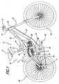
- a bicycle as shown in Figure 1 , has a bicycle frame 10 with a rear suspension system.
- the bicycle frame 10 is made-up of a main frame 2, a shock absorber 4 and a sub-frame 6.
- a main frame 2 has a seat tube 21, a top tube 23 and a head tube 25.
- the top tube 23 can connect the seat tube 21 and the head tube 25.
- a seat post 8 with an attached saddle 12 can be installed in the seat tube 21.
- a steering post or column 14 which connects the handle bars 16 and the fork 18 can be installed in the head tube 25.
- the fork can support the front wheel 30.
- Some assemblies may further include a down tube 27 and a bottom bracket 29.
- the down tube 27 can connect the bottom bracket 29 and the head tube 25.
- a crank 20 can be installed into the bottom bracket 29 to which pedals 22 can be attached.
- the main frame 2 may further include one or more gussets or cross tubes 24.
- the cross tubes can connect various parts of the main frame 2.
- the cross tube 24 connects the seat tube 21 and the top tube 23.
- Cross tubes 24 can increase the frame's stability and allow for additional design features, such as a downward sloping top tube 23.
- the bicycle frame 10 also includes a sub-frame 6 and a shock absorber 4.
- the sub-frame 6 is movable relative to the main frame 2.
- the shock absorber 4 regulates movement between the sub-frame 6 and the main frame 2.
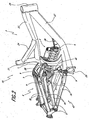
- a pivot axis P is shown in Figures 1-2 to illustrate the various points of rotation on the bicycle frame 10.
- the sub-frame 6 can include a pair of seat stays 32 and a pair of chain stays 34.
- Each seat stay 32 can connect with a corresponding chain stay 34 and can support a rear wheel 30. This connection can be fixed or pinned to allow for rotation.
- the chain stays 34 may be hingedly connected to the main frame at or near the bottom bracket 29.
- a link 36 can also be used to connect the main frame 2 and sub-frame 6.
- the link 36 is pivotally connected to the main frame 2 and sub-frame 6
- the link 36 may be attached to the shock absorber 4, instead of, or in addition to, either the main frame 2 or the sub-frame 6.
- a forward end of the shock absorber 4 is shown rotatably coupled to the main frame 2 for a rotation about a pivot axis P.
- This pivot axis P can be defined by a shock mount 38.
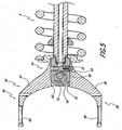
- a rearward end of the shock absorber 4 is coupled to an extension body 40 which is rotatably coupled to the sub-frame 6 and, more specifically, to a shock mount assembly 42 for a rotation about a pivot axis P.
- the shock mount assembly 42 can include a first arm 44 and a second arm 46 that, along with the chain stays 34, define an essentially triangular shape in plan view.
- the shock absorber 4 can be used to control the amount of movement between the main frame 2 and the sub-frame 6 and the rate of change in their relationships.
- pivot axis P is used in some of the figures, such as Figure 2 , to show the various pivot points where some of the different components of the bicycle frame 10 are connected.
- the pivot axis P can define connection points which in some embodiments and in some locations can include bushings, or bearings, though this is not required.
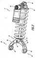
- the shock absorber 4 can be a commonly available fluid and/or coil spring shock absorber.
- the fluid may be oil and/or air.
- the shock absorber 4 shown has an eyelet 48, 50 at either end to attach the shock absorber 4 to a bicycle frame as part of a rear suspension.
- the shock absorber can be a commonly available shock
- the shock absorber 4 used here has been adjusted or modified, such that the rear eyelet 50 is perpendicular to the typical axis of rotation and, in fact, the rear eyelet 50 is not used for rotation.
- the center axis A 1 of the opening of the rear eyelet 50 is offset 90 degrees from the center axis A 2 of the opening of the front eyelet 48. This can generally be done by simply rotating the eyelet 50 and shaft of the shock absorber by hand in relation to the other eyelet 48 to reach the desired position and orientation.
- the shock absorber 4 can also have adjustment controls 52.
- the adjustment controls 52 can include adjustments for dampening, rebound, pressure and other adjustments.
- the adjustment controls can include adjustment knobs, a Schrader or Presta valve, and/or a preloading ring as are known in the art.
- the extension body 40 has a first end 54 and a second end 56.
- the first end 54 can be configured to receive an eyelet 48, 50 of a shock absorber 4 and the second end 56 can be configured to connect to a bicycle frame 10.
- the second end of the extension body 40 and the bicycle frame 10 can be pivotally connected.
- the connection point may include bearings, bushings or other features to reduce friction and allow for smooth rotation and movement.
- the extension body 40 can be used to effectively increase the length of the shock absorber 4. This increased length of the shock 4 can change the pivot points at which the shock absorber 4 is attached to the bicycle frame 10 and can thereby change the relative motions that the shock absorber 4, main frame 2 and sub-frame 6 experience in relation to one another.
- the second end 56 of the extension body may include a pair of extension arms 58.
- Each extension arm 58 can have an eyelet 60.
- the extension arms 42 can allow the shock absorber 4 to span part, or all, of the rear wheel, the seat tube or other parts of the bicycle. In this way, extension arms 58 allow the extension body to, not only move the rear the pivot location of the shock absorber 4 to a more distant location, but also to locate the rear pivot to a spot not previously available or possible. For example, the extension arms can move the pivot location to the sides of the wheel, where previously, the rear pivot of the shock absorber could only be located in front of the rear wheel.
- the extension arms also provide additional benefits as detailed below.
- extension bodies 40 Another feature of certain variants of extension bodies 40, is an inner surface 62 defining a cavity configured to receive an eyelet 48, 50 of the shock absorber 4.
- the inner surface 62 can be contoured or shaped to receive the eyelet.
- the inner surface 62 can be shaped to receive the eyelet of any of the many commonly available or custom shock absorbers.
- the inner surface may be contoured, such as to form a round cavity shaped to closely match the outside surface of the eyelet
- the extension body 40, and/or the first end 54 of the extension body can be hollow to allow for various different configurations of eyelets and shock absorber ends to fit within the extension body 40.
- the inner surface can closely fit the eyelet so as to restrict rotation and/or other movement between the extension body and the shock absorber. A looser fit can be provided. This can permit the selection of a wider variety of shape of mating eyelets and/or shock absorbers.
- the inner surface 62 can be configured to receive an eyelet 50 of a shock absorber 4 that has been rotated or modified to be offset 90 degrees from the typical orientation of the eyelet, such as 90 degrees from the orientation of the other eyelet 48.
- the inner surface 62 can be formed to create a cavity closed at all but one end.
- the inner surface 62 may form a cavity that is open at the front and back of the cavity, where the cavity passes through the extension body 40 ( Figure 5 ).
- the first end 54 of the extension body 40 can be hollow and can include an opening or slit 64.
- the slit 64 can extend from the first end 54 to the second end 56.
- the slit 64 may extend into at least part of the extension arms 58.
- the slit 64 can allow the top and bottom of the first end 54 of the extension body 40 to be clamped down on the eyelet, and/or end of the shock absorber, to secure the same in place within the extension body 40. This can allow a rigid connection to be formed between the shock absorber 4 and the extension body 40.
- a fastener 66 such as a bolt and nut, can be used to secure the shock absorber 4 and extension body 40 together.
- the extension body and shock absorber can substantially prevent rotation between these two mating bodies.
- the inner surface 62 and/or the fastener 66 can be used to substantially prevent rotation.
- Substantially prevent rotation can include rotating less than 25°, 20°, 15°, 10°, 5°, 3°, 2°, and 1°.
- the extension body 40 can also include one or more slots or holes, to accommodate certain features on or near the eyelet and the end of the shock absorber 4.
- a slot 68 can be located at the first end 54 to accommodate an adjustment control 52 such as a rebound knob, located near the eyelet.
- a stock or custom shock absorber 4 can be provided, wherein an adjustment control 52 near an eyelet or shock end is replaced with a modified adjustment control 52, designed for use with an extension body 40.
- the new adjustment control 52 can be smaller, larger, longer, etc. or some other shape different from the original.
- shock absorber 4 may have an additional outside fluid reservoir (not shown).
- a hole or slot in the extension body 40, such as slot 68, can be configured to accommodate a hose for connecting the shock absorber 4 to the fluid reservoir.
- extension body 40 that can receive a number of commonly available or custom shock absorbers provides great benefits to both the manufacturer and the end consumer.
- the extension body is interchangeable with different shocks and therefore can be used on different bicycles and those bicycles can be upgraded, modified or repaired to incorporate different or similar shocks depending on consumer preference or as required. This also reduces cost for the manufacturer because different extension bodies do not need to be manufactured for use with different shocks and/or bikes, and custom shocks do not have to be manufactured.
- Extension arms can beneficially allow a bicycle manufacturer to create its own pivot point for the shock absorber, rather than being required to use the rear shock absorber eyelet.
- the surface of the extension arms can be used to create a stronger, more durable, and smoother connection and pivot.
- cartridge ball bearings which are smoother and more durable, can be used at the interface between the extension arm and the sub-frame.
- the extension arms also beneficially allow the rear shock absorber pivot to be placed in locations that were previously impossible, for example, at the sides of the tires. Also, the extension arms allow the shock pivot points to be placed in more optimal locations.
- the shock absorber 4 can be placed in a compact, lower profile orientation within the frame and still achieve a shock leverage motion which matches that of other bikes with a higher or not as compact orientation.
- the extension body 40 can provide a robust shock absorber-extension body interface. With the extension body 40 as shown and discussed above, the connection between the extension body and the eyelet is strengthened by rotating the eyelet 90 degrees to its typical orientation.
- the extension body can be configured to receive an eyelet rotated between 80-100°, 60-120°, 40-140°. This can include angle between the axis of at least 15°, 30°, 45°, 60°, 75°, 80°, 85°. This can reduce the interface strength requirements and prevent the tendency of the shock absorber-extension body interface to rotate or buckle. There is a reduced propensity to rotate about the typical eyelet axis (parallel to A 2 ) at the interface because the eyelet is perpendicular, or at least not parallel, to its typical orientation.
- extension arms further reduce the propensity of the interface to rotate about the axis A 1 of the new eyelet orientation. This is because of the wide bracing provided by the extension body which can form a wide v-shaped or y-shaped yoke. The wide bracing reduces the tendency of the interface to rotate about the new eyelet axis A 1 .
- Rotating or modifying the shock absorber 4, so that the eyelet 50 is rotated 90 degrees from its typical position, can also beneficially move certain of the adjustment controls 52 to the side.
- Having adjustment controls 52 on the side of the bicycle can have many benefits. For example, the user can visually and clearly see the adjustments being made. If the user is standing next to the bicycle making the adjustments, they are likely to be on the side of the bike and will be able to easily see the adjustments being made. They will have a clear unobstructed view of the adjustment control 52 plus any setting markings. If the user is on the bike, it is easy for them to reach down and make an adjustment with a normal rotational movement of their hand.
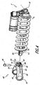
- a fastener 66 such as a bolt can be used to secure the eyelet 50 within the extension body 40.
- the fastener 66 can have an outside diameter that fills or is smaller than the eyelet 50.
- the fastener 66 is smaller than the eyelet 50 and a spacer 70 is used to create a tight fit between the fastener and the eyelet. It can be desirable to provide a rigid and secure connection between the shock absorber 4 and the extension body 40.
- the fastener, the fastener and spacer and/or other features can be used to create a rigid and secure connection.
- the extension body 40 can include a hole 74 for the fastener to pass through (See Figure 4 ).
- the hole 74 can pass through all or part of the extension body 40 and can pass through any of the top, bottom and/or sides of the extension body 40. As shown, the hole 74 passes from the top to the bottom. Alternatively, the hole 74 may pass through the side or at an angle. A part or all of the hole 74 may be threaded or unthreaded.
- the spacer 70 can be placed within the eyelet 50 and the eyelet 50 can then be advanced into the cavity defined by the inner surface 62 in the extension body 40.
- the spacer 70 can also have a hole 72 for the fastener 66 to pass through. As already mentioned, the fastener 66 can secure the spacer 70, and thereby the eyelet 50, within the extension body 40.
- the hole 72 in a spacer 70 can determine where the fastener 66 passes through the eyelet.
- the eyelets of a typical shock absorber are round.
- the spacer 70 can also be round or other shapes that can fit within the eyelet.
- the hole 72 in the spacer 70 can be centered with the spacer or off-center.
- the hole 72 in the spacer and within the eyelet can determine where the fastener passes through the eyelet and can thereby determine a spatial relationship between the shock absorber and the extension body.
- a spacer 70 with an off-center hole 72 can also be used to adjust the relationship of the shock absorber 4 and the extension body 40.
- the spacer can be placed within the eyelet so as to line up with the hole 74 in one of two positions. The two positions of the spacer can be about 180° apart. In one position, the hole 72 can be positioned to be closer to the first end 54 and in another position, the hole 72 can be positioned to be closer to the second end 56. In this way, the position of the hole 72 within the eyelet 50 can be used to lengthen or shorten the total length of the shock/extension body combination.
- the spacer 70 can include more than one hole 72. The different holes can be different distances away from the center or sides of the spacer. Selection of which hole 72 in the spacer 70 to use can then determine the total length of the shock/extension body combination.
- the extension body 40 can include two or more holes 74, so that the selection of the particular hole 74 can be used to adjust the relationship of the extension body 40 and shock absorber 4.
- a spacer 70 with an off-center hole 72 can be used to further increase the adjustability of the extension body and shock absorber positions within the particular selected hole 74.
- the rear suspension linkage By changing the length of the shock/extension body combination, the rear suspension linkage extends or compresses its neutral static state.
- the byproduct of this is the raising or lowering of the crank height, or steepening or slackening the steering geometry.
- the fastener 66 and hole 74 can be used to prevent rotation of the extension body and shock absorber, instead of or in addition to the inner surface 62.
- the inner surface 62 can be used simply to maintain the eyelet within the cavity defined by the inner surface 62.
- both the fastener 66/hole 74 combination and the inner surface 62 are used to prevent rotation and distribute forces over a wider surface area.
Landscapes
- Engineering & Computer Science (AREA)
- Mechanical Engineering (AREA)
- Axle Suspensions And Sidecars For Cycles (AREA)
Claims (6)
- Fahrrad-Aufbau, welcher umfasst,:a Rahmen (2, 6), der einen Haupt-Rahmen (2), einen Stoßdämpfer (4), und einen Unter-Rahmen (6) umfasst;worin der Haupt-Rahmen (2) eine Sattelstange (21), eine Kopfstange (25) und eine obere Stange (23) aufweist, die die Sattelstange und die Kopfstange verbindet;worin der Unter-Rahmen (6) ausgestaltet ist, sich hinsichtlich des Haupt-Rahmens zu drehen, worin der Rahmen (2, 3) ausgestaltet ist, das Verhältnis zwischen dem Haupt-Rahmen (2) und dem Unter-Rahmen (6) mittels des Stoßdämpfers zu regulieren (4), der ein erstes durchgezogenes Gewindeloch (48) zur Verbindung des Haupt-Rahmens umfasst und ein zweites durchgezogenes Gewindeloch (50);einen Auszieh-Körper (40) mit einem ersten Bereich (54), der ausgestaltet ist, mit dem zweiten durchgezogenen Gewindeloch des Stoßdämpfers und einem zweiten Bereich (56) verbunden zu werden;ein Befestigungsmittel (66), um den Auszieh-Körper und das zweite durchgezogene Gewindeloch des Stoßdämpfers zu sichern; undeinen Abstandshalter (70) mit einem exzentrisch angeordneten Loch (72), um das Befestigungsmittel aufzunehmen,dadurch gekennzeichnet, dassder Abstandshalter (70) ausgestaltet ist, in dem zweiten durchgezogenen Gewindeloch (50) zu sitzen, so dass die Position des Abstandshalters (70) in dem durchgezogenen Gewindeloch (50) einem Nutzer ermöglicht, eine Länge des Stoßdämpfers (4) und des Auszieh-Körpers (40) einzustellen.
- Fahrradaufbau nach Anspruch 1, worin das zweite durchgezogene Gewindeloch senkrecht zu einer Rotationsachse des ersten durchgezogenen Gewindelochs steht.
- Fahrradaufbau nach Anspruch 1, worin das zweite durchgezogene Gewindeloch um 90° von dem ersten durchgezogenen Gewindeloch versetzt ist.
- Fahrradaufbau nach Anspruch 1, worin der Auszieh-Körper zwei oder mehrere Auszieh-Körper-Löcher (74) zur Aufnahme des Befestigungsmittels umfasst und durch Wahl des Auszieh-Körper-Lochs eine weitere Einstellung der Länge des kombinierten Stoßdämpfers und Auszieh-Körpers ermöglicht.
- Fahrradaufbau nach Anspruch 1, worin der zweite Bereich des Auszieh-Körpers ein Paar Erstreckungsarme (58) umfasst, die ausgestaltet sind, ein Hinterrad derart zu überspannen, dass ein hinterer Schwenkpunkt des Stoßdämpfers an den Seiten des Hinterrads ist, worin der vordere Schwenkpunkt an dem ersten durchgezogenen Gewindeloch des Stoßdämpfers ist.
- Fahrradaufbau nach Anspruch 1, welcher weiter eine Gabel (18), einen Sattel (12) und zwei Räder (30) umfasst.
Applications Claiming Priority (2)
| Application Number | Priority Date | Filing Date | Title |
|---|---|---|---|
| US12/780,710 US8006993B1 (en) | 2010-05-14 | 2010-05-14 | Bicycle frame |
| EP11710957.9A EP2569213B1 (de) | 2010-05-14 | 2011-03-14 | Fahrradrahmen |
Related Parent Applications (3)
| Application Number | Title | Priority Date | Filing Date |
|---|---|---|---|
| PCT/US2011/028377 Previously-Filed-Application WO2011142882A1 (en) | 2010-05-14 | 2011-03-14 | Bicycle frame |
| EP11710957.9A Division EP2569213B1 (de) | 2010-05-14 | 2011-03-14 | Fahrradrahmen |
| EP11710957.9A Division-Into EP2569213B1 (de) | 2010-05-14 | 2011-03-14 | Fahrradrahmen |
Publications (2)
| Publication Number | Publication Date |
|---|---|
| EP2907736A1 EP2907736A1 (de) | 2015-08-19 |
| EP2907736B1 true EP2907736B1 (de) | 2016-09-07 |
Family
ID=44486200
Family Applications (3)
| Application Number | Title | Priority Date | Filing Date |
|---|---|---|---|
| EP11710957.9A Active EP2569213B1 (de) | 2010-05-14 | 2011-03-14 | Fahrradrahmen |
| EP15150465.1A Active EP2907735B1 (de) | 2010-05-14 | 2011-03-14 | Fahrradrahmen |
| EP15150469.3A Active EP2907736B1 (de) | 2010-05-14 | 2011-03-14 | Fahrradrahmen |
Family Applications Before (2)
| Application Number | Title | Priority Date | Filing Date |
|---|---|---|---|
| EP11710957.9A Active EP2569213B1 (de) | 2010-05-14 | 2011-03-14 | Fahrradrahmen |
| EP15150465.1A Active EP2907735B1 (de) | 2010-05-14 | 2011-03-14 | Fahrradrahmen |
Country Status (4)
| Country | Link |
|---|---|
| US (5) | US8006993B1 (de) |
| EP (3) | EP2569213B1 (de) |
| TW (2) | TWI436920B (de) |
| WO (1) | WO2011142882A1 (de) |
Families Citing this family (63)
| Publication number | Priority date | Publication date | Assignee | Title |
|---|---|---|---|---|
| CN101068709B (zh) | 2004-09-15 | 2011-06-08 | 耶蒂自行车有限责任公司 | 用于自行车的后悬挂系统 |
| US8162344B2 (en) | 2007-07-03 | 2012-04-24 | Yeti Cycling, Llc | Outboard axle bearing structure for a bicycle or motorcycle |
| US20110187078A1 (en) * | 2010-02-02 | 2011-08-04 | Mark Antony Higgon | Rear suspension unit for after market use in folding bikes |
| US8006993B1 (en) | 2010-05-14 | 2011-08-30 | Specialized Bicycle Components, Inc. | Bicycle frame |
| US9821879B2 (en) | 2010-08-20 | 2017-11-21 | Yeti Cycling, Llc | Reciprocating rail movement suspension system |
| WO2012024697A1 (en) | 2010-08-20 | 2012-02-23 | Peter Zawistowski | Link suspension system |
| US9216791B2 (en) * | 2011-03-14 | 2015-12-22 | Christopher Hudec | Bicycle suspension system |
| EP2686227B1 (de) * | 2011-03-14 | 2020-02-19 | CMH Plus Holdings Ltd. | Fahrrad |
| USD694156S1 (en) * | 2011-11-15 | 2013-11-26 | Bike Concept Oy | Bicycle |
| WO2013192622A1 (en) * | 2012-06-23 | 2013-12-27 | Bicycle Fabrications Llc | Bicycle rear suspension with a two axis wheel path |
| US10766563B2 (en) | 2013-01-16 | 2020-09-08 | Yeti Cyclying, Llc | Rail suspension with integral shock and dampening mechanism |
| US9242693B2 (en) * | 2013-03-15 | 2016-01-26 | Darrell W. Voss | Bicycle rear suspension |
| USD721013S1 (en) * | 2014-05-02 | 2015-01-13 | Product Development Technologies, Inc. | Bicycle with kickstand and docking station |
| USD719488S1 (en) | 2013-07-03 | 2014-12-16 | Specialized Bicycle Components, Inc. | Bicycle frame |
| USD719880S1 (en) | 2013-07-03 | 2014-12-23 | Specialized Bicycle Components, Inc. | Bicycle frame |
| JP1524699S (de) * | 2013-11-20 | 2015-06-01 | ||
| FR3018062A1 (fr) * | 2014-02-28 | 2015-09-04 | Cycles Lapierre | Perfectionnement a un systeme de suspension pour bicyclette |
| USD727215S1 (en) * | 2014-03-05 | 2015-04-21 | Tai-Her Yang | Electric bicycle |
| AU356322S (en) * | 2014-05-29 | 2014-07-08 | A bicycle frame | |
| CN106536340B (zh) * | 2014-06-25 | 2020-10-30 | 瓦斯泰克知识产权有限公司 | 自行车后轮悬架系统 |
| USD774972S1 (en) * | 2014-10-31 | 2016-12-27 | Piaggio & C. S.P.A. | Electric bicycle |
| USD774970S1 (en) | 2015-02-27 | 2016-12-27 | Specialized Bicycle Components, Inc. | Bicycle frame |
| US10073890B1 (en) | 2015-08-03 | 2018-09-11 | Marca Research & Development International, Llc | Systems and methods for patent reference comparison in a combined semantical-probabilistic algorithm |
| US10621499B1 (en) | 2015-08-03 | 2020-04-14 | Marca Research & Development International, Llc | Systems and methods for semantic understanding of digital information |
| ITUB20154242A1 (it) * | 2015-10-08 | 2017-04-08 | Andrea Pedretti | Telaio di bicicletta |
| CN106043571A (zh) * | 2015-10-13 | 2016-10-26 | 无锡市嘉德机械有限公司 | 具有减震功能的车架 |
| CN105539700A (zh) * | 2015-12-28 | 2016-05-04 | 天津博利自行车有限公司 | 一种多功能自行车车架 |
| CN105460147A (zh) * | 2015-12-28 | 2016-04-06 | 天津博利自行车有限公司 | 一种具有缓震功能的自行车架 |
| US10540439B2 (en) | 2016-04-15 | 2020-01-21 | Marca Research & Development International, Llc | Systems and methods for identifying evidentiary information |
| CA171388S (en) * | 2016-05-13 | 2017-06-13 | Zhejiang Right Digital Tech Co Ltd | Electric bicycle |
| PL242285B1 (pl) * | 2016-05-25 | 2023-02-06 | Loop Spolka Z Ograniczona Odpowiedzialnoscia | Rama amortyzowana pojazdów jednośladowych |
| PL229197B1 (pl) | 2016-05-25 | 2018-06-29 | Dabrowski Jerzy | Układ zawieszenia tylnego koła pojazdów jednośladowych |
| USD807234S1 (en) * | 2016-09-15 | 2018-01-09 | Accell North America, Inc. | Bicycle frame |
| CN106515971A (zh) * | 2016-10-26 | 2017-03-22 | 索罗门兴业(天津)科技有限公司 | 减震式自行车 |
| EP3595963A4 (de) | 2017-03-17 | 2021-03-10 | Yeti Cycling, LLC | Fahrzeugaufhängungsgelenk |
| CN107150755A (zh) * | 2017-03-20 | 2017-09-12 | 深圳市人行者科技有限公司 | 一种曲线车架 |
| US10870461B2 (en) | 2017-03-23 | 2020-12-22 | Darrell W. Voss | Vehicle component |
| US10723410B2 (en) | 2017-03-23 | 2020-07-28 | Darrell W Voss | Vehicle |
| US11548587B2 (en) | 2017-03-23 | 2023-01-10 | Darrell W Voss | Vehicle |
| US10618595B2 (en) | 2017-03-23 | 2020-04-14 | Darrell W Voss | Vehicle |
| US10457349B2 (en) | 2017-03-23 | 2019-10-29 | Darrell W. Voss | Vehicle component |
| EP3649040A4 (de) | 2017-07-07 | 2021-03-10 | Yeti Cycling, LLC | Fahrzeugaufhängungsgelenk |
| CN108100138A (zh) * | 2017-12-26 | 2018-06-01 | 齐杰 | 自行车车架及其自行车组件 |
| US10661855B2 (en) | 2018-01-26 | 2020-05-26 | Specialized Bicycle Componenets, Inc. | Bicycle suspension with shock strut |
| US10850796B2 (en) * | 2018-03-30 | 2020-12-01 | Specialized Bicycle Components, Inc. | Bicycle rear suspension |
| US10850798B2 (en) | 2018-03-30 | 2020-12-01 | Specialized Bicycle Components, Inc. | Bicycle rear suspension |
| US10850799B2 (en) * | 2018-04-05 | 2020-12-01 | Specialized Bicycle Components, Inc. | Adjustable bicycle suspension |
| CA3015256A1 (en) * | 2018-08-24 | 2020-02-24 | Clark A. Wallace | Bicycle frame assembly |
| US12077241B2 (en) | 2019-02-01 | 2024-09-03 | Yeti Cycling, Llc | Multi-body vehicle suspension linkage |
| US12145684B2 (en) | 2019-12-24 | 2024-11-19 | Yeti Cycling, Llc | Constrained multiple instantaneous velocity center linkage assembly for vehicle suspension |
| US11780528B2 (en) | 2020-05-21 | 2023-10-10 | Specialized Bicycle Components, Inc. | Adjustable head angle bicycles |
| CN115968346B (zh) * | 2020-07-10 | 2025-03-07 | 株式会社维他命爱工厂 | 练习用自行车及自行车车架 |
| USD958702S1 (en) | 2020-08-05 | 2022-07-26 | Specialized Bicycle Components, Inc. | Bicycle frame |
| US12384484B2 (en) | 2020-11-18 | 2025-08-12 | Yeti Cycling, Llc | Integrated motor mount and suspension pivot |
| USD999120S1 (en) * | 2021-08-12 | 2023-09-19 | El Camos S.R.L. | Bicycle frame |
| US20230063529A1 (en) * | 2021-09-01 | 2023-03-02 | Suspension Formulas, LLC | Bicycle rear suspension system |
| US20240227969A1 (en) * | 2023-01-06 | 2024-07-11 | Toyota Motor Engineering & Manufacturing North America, Inc. | Bicycle frame with vibration isolation |
| AT526916A1 (de) | 2023-01-26 | 2024-08-15 | Ktm Ag | Fahrrad-Baugruppe |
| USD1069698S1 (en) | 2023-03-16 | 2025-04-08 | Annex Products Pty. Ltd. | Wireless charging mount |
| PL444243A1 (pl) * | 2023-03-30 | 2024-10-07 | Loop Spółka Z Ograniczoną Odpowiedzialnością | Zespół amortyzacji ramy rowerowej |
| USD1101633S1 (en) * | 2024-08-29 | 2025-11-11 | Shenzhen Wins Sport Technology Co., Ltd | Suspension linkage |
| USD1101632S1 (en) * | 2024-08-29 | 2025-11-11 | Shenzhen Wins Sport Technology Co., Ltd | Suspension linkage |
| USD1083688S1 (en) * | 2025-01-10 | 2025-07-15 | Shenzhen yingfeinuo technology co., LTD | Bicycle |
Family Cites Families (89)
| Publication number | Priority date | Publication date | Assignee | Title |
|---|---|---|---|---|
| US578614A (en) | 1897-03-09 | Bicycle or like vehicle | ||
| US564319A (en) | 1896-07-21 | Bicycle or like vehicle | ||
| US712784A (en) | 1902-09-10 | 1902-11-04 | Robert Ellis | Bicycle-frame. |
| US1075886A (en) | 1906-03-09 | 1913-10-14 | Edward Y White | Frame for motor-bicycles. |
| US1298958A (en) | 1917-10-11 | 1919-04-01 | William Johnston | Bicycle-frame. |
| US1272399A (en) * | 1918-01-22 | 1918-07-16 | William Douglas | Cycle. |
| US1340508A (en) * | 1920-02-02 | 1920-05-18 | Walker Reginald Eric | Spring-frame for motorcycles |
| US1413352A (en) * | 1922-01-12 | 1922-04-18 | Peters James Arthur | Spring fork for motor cycles |
| US2238411A (en) * | 1939-06-28 | 1941-04-15 | Conklin Fred | Combination shock absorber and extension leg |
| US3679029A (en) * | 1971-04-21 | 1972-07-25 | James H Thomas | Shock absorber extension |
| JPS5131437A (en) | 1974-09-12 | 1976-03-17 | Yamaha Motor Co Ltd | Nirinsha |
| US4013149A (en) * | 1974-11-25 | 1977-03-22 | Fabre Brian K | Extender for increasing the travel of motorcycle shock absorbers |
| US4046396A (en) | 1976-02-25 | 1977-09-06 | James Michael Morrison Taylor | Heavy duty dirt bicycle and frame therefor |
| US4189168A (en) | 1978-04-28 | 1980-02-19 | Courtney Orley R | Wheel suspension system for a vehicle |
| US4378857A (en) | 1981-01-16 | 1983-04-05 | Erland Andersson | Motor-cycle frame |
| US4697659A (en) * | 1986-04-24 | 1987-10-06 | Zimmerman Tony J | Vehicle fraction attachment |
| US4789174A (en) * | 1987-04-27 | 1988-12-06 | Mert Lawwill | Suspension bicycle |
| US5509679A (en) * | 1992-01-21 | 1996-04-23 | 89908, Inc. | Rear suspension for bicycles |
| US5244224A (en) * | 1992-05-14 | 1993-09-14 | Gt Bicycles, Inc. | Rocker arm rear suspension bicycle |
| US5269552A (en) * | 1992-09-03 | 1993-12-14 | Gt Bicycles, Inc. | Bicycle frame composition |
| SE506443C2 (sv) | 1992-12-09 | 1997-12-15 | Oehlins Racing Ab | Anordning vid stötdämpare |
| JPH07223577A (ja) | 1994-02-15 | 1995-08-22 | Bridgestone Cycle Co | 緩衝装置付き自転車フレーム |
| JP3313228B2 (ja) | 1994-02-22 | 2002-08-12 | 株式会社ショーワ | 緩衝器 |
| JPH0880887A (ja) * | 1994-09-13 | 1996-03-26 | Honda Motor Co Ltd | 自動2輪車の後輪懸架装置 |
| US5498013A (en) * | 1994-12-12 | 1996-03-12 | Hwang; Chiuon T. | Bicycle frame having shock absorbing device |
| US5725227A (en) * | 1995-07-20 | 1998-03-10 | Schwinn Cycling & Fitness Inc. | Suspension system for a bicycle |
| US5671936A (en) * | 1995-08-10 | 1997-09-30 | Turner; David Roy | Shock absorbing bicycle frame apparatus |
| US6109636A (en) * | 1995-08-25 | 2000-08-29 | Klein Bicycle Corporation | High efficiency bicycle frame suspension |
| USD401187S (en) * | 1996-03-05 | 1998-11-17 | Bayerische Motoren Werke Aktiengesellschaft | Bicycle frame |
| DE29618383U1 (de) | 1996-10-28 | 1998-01-08 | Kramer-Massow, Klaus, 79299 Wittnau | Hinterradzweiradfederung in der Ausführung eines Viergelenksystemes |
| US5791674A (en) * | 1997-03-13 | 1998-08-11 | Cannondale Corporation | Bicycle suspension system |
| USD402926S (en) * | 1997-03-15 | 1998-12-22 | Dr. Ing.H.C.F. Porsche Ag | Bicycle frame assembly |
| USD398267S (en) * | 1997-06-06 | 1998-09-15 | Chih-Yung Yu | Bicycle frame |
| US6039137A (en) | 1998-02-10 | 2000-03-21 | Schless; Ely | Multi-terrain electric motor driven cycle |
| US6880846B2 (en) * | 1998-03-27 | 2005-04-19 | Carl W. Schonfeld | Bicycle with shock absorber |
| SE515321C2 (sv) | 1998-12-02 | 2001-07-16 | Oehlins Racing Ab | Stötdämpare med cylinder innefattande en kolvstång med minst två kolvar |
| US6318521B1 (en) * | 1999-06-16 | 2001-11-20 | Bridgestone/Firestone, Inc. | Externally guided ER damper |
| DE19939515C2 (de) * | 1999-08-20 | 2002-06-13 | Porsche Ag | Federbein für ein Kraftfahrzeug mit einer Lagerung für eine Schraubenfeder |
| US6361059B1 (en) * | 1999-09-10 | 2002-03-26 | Anthony S. Ellsworth | Single pivot bicycle suspension apparatus and related methods |
| US6224080B1 (en) * | 1999-10-22 | 2001-05-01 | Bennett Ross | Spokeless bicycle system |
| US6279703B1 (en) | 2000-05-15 | 2001-08-28 | A-Pro Cycles, Inc. | Shock absorbing adjusting structure |
| US20030205882A1 (en) | 2001-05-16 | 2003-11-06 | Parkin Michael James | Living hinge member and suspension |
| GB2366263B (en) * | 2000-08-25 | 2002-07-10 | Jeffery Ernest Amos | Bicycle frame |
| FR2827831B1 (fr) | 2001-07-26 | 2004-04-16 | Promiles | Vehicule deux roues a suspension arriere |
| US6843494B2 (en) | 2001-08-22 | 2005-01-18 | Rocky Mountain Bicycles | Rear suspension system for two-wheeled vehicles, particularly bicycles |
| US7273137B2 (en) | 2001-08-30 | 2007-09-25 | Fox Factory, Inc. | Inertia valve shock absorber |
| GB2381510B (en) | 2001-11-01 | 2004-01-07 | Atb Sales Ltd | Bicycle rear suspension |
| GB2382551A (en) * | 2001-11-28 | 2003-06-04 | Far Great Plastics Ind Co Ltd | Bicycle with rear wheel shock absorber |
| USD491111S1 (en) * | 2002-02-13 | 2004-06-08 | Honda Giken Kogyo Kabushiki Kaisha | Bicycle |
| DE10208560B4 (de) * | 2002-02-27 | 2006-01-19 | Zf Sachs Ag | Befestigungselement mit multifunktionalem Befestigungsteil |
| DE20205539U1 (de) | 2002-04-10 | 2002-07-25 | Derby Cycle Werke GmbH, 49661 Cloppenburg | Zweiradrahmen, insbesondere Fahrradrahmen |
| US20040061305A1 (en) | 2002-09-30 | 2004-04-01 | Christini Steven J. | Rear wheel suspension system for a bicycle |
| DE102004001933A1 (de) | 2004-01-14 | 2005-08-11 | Zf Friedrichshafen Ag | Befestigungselement mit multifunktionalem Befestigungsteil |
| TW564855U (en) | 2003-04-08 | 2003-12-01 | Yung-Feng Shiu | Shock absorption crank structure for bicycle frame |
| US7052028B2 (en) * | 2003-06-11 | 2006-05-30 | Specialized Bicycle Componets, Inc. | Frame assembly for a bicycle |
| ES2237305B2 (es) | 2003-10-01 | 2006-03-16 | Orbea S.Coop.Ltda. | Suspension trasera para bicicletas. |
| US6978985B2 (en) * | 2003-10-16 | 2005-12-27 | Pro-Glory Enterprise Co., Ltd. | Mechanism type non-sectional locking buffer device |
| DE10348971A1 (de) | 2003-10-22 | 2005-05-25 | Zf Friedrichshafen Ag | Dämpfungselement |
| US6877591B1 (en) * | 2003-11-17 | 2005-04-12 | Yung-Feng Hso | Crank of a shock absorber for a bicycle |
| US7467803B2 (en) * | 2003-12-12 | 2008-12-23 | Noel Buckley | Rear suspension system for bicycles |
| NZ531898A (en) | 2004-03-23 | 2006-01-27 | David Evans | Cycle suspension assembly |
| USD523380S1 (en) * | 2004-06-14 | 2006-06-20 | Cycles Devinci Inc. | Double suspension bicycle frame |
| US8152191B2 (en) | 2004-06-29 | 2012-04-10 | Giant Manufacturing Co., Ltd. | Bicycle suspension system |
| US7216883B2 (en) | 2005-03-02 | 2007-05-15 | Rocky Mountain Bicycles-A Division Of Procycle Group Inc. | Bicycle with rear suspension |
| WO2007036225A2 (de) | 2005-09-30 | 2007-04-05 | Andreas Felsl | Zweiradrahmen, hinterradschwinge und gabelanordnung |
| FR2898577B1 (fr) | 2006-03-15 | 2009-02-13 | Cycles Lapierre Soc Par Action | Perfectionnement a une suspension arriere d'un vehicule |
| US7413208B2 (en) | 2006-04-20 | 2008-08-19 | Astro Engineering Co., Ltd. | Bicycle frame |
| US7717212B2 (en) * | 2006-08-25 | 2010-05-18 | Split Pivot, Inc. | Vehicle suspension systems for seperated acceleration responses |
| US20080054595A1 (en) | 2006-09-01 | 2008-03-06 | Lu Daniel T F | Bicycle frame with a counter-rotating four bar linkage system |
| FR2912110B1 (fr) | 2007-02-05 | 2009-04-24 | Promiles Snc | Vehicule a deux roues a suspension arriere |
| US7374191B1 (en) | 2007-03-14 | 2008-05-20 | Merida Industry Co., Ltd. | Bicycle frame |
| CA2621044C (en) * | 2007-06-07 | 2015-04-28 | Rocky Mountain Bicycles - A Division Of Procycle Group Inc. | Bicycle rear suspension system |
| US7815207B2 (en) | 2007-06-28 | 2010-10-19 | Currie Christopher S | Rear wheel suspension system for a two-wheeled vehicle |
| US7934739B2 (en) * | 2007-07-27 | 2011-05-03 | Niner, Inc. | Bicycle rear suspension |
| TW200914320A (en) * | 2007-09-19 | 2009-04-01 | A Pro Tech Co Ltd | Rear shock absorption device for bicycle |
| US8136829B1 (en) | 2008-04-04 | 2012-03-20 | Kang Alan H | Force channelling centralization mountain bike and frame |
| US7703788B2 (en) | 2008-04-04 | 2010-04-27 | Tanouye Ted K | Force channeling mountain bike rear suspension |
| US20100007113A1 (en) | 2008-07-11 | 2010-01-14 | David Earle | Rear suspension system for bicycles |
| US7909347B2 (en) | 2008-09-11 | 2011-03-22 | A-Pro Tech Co., Ltd | Bicycle suspension system employing highly predictable pedalling characteristics |
| EP2337730A4 (de) | 2008-09-16 | 2013-09-18 | Evil Bikes Llc | Verbesserte fahrradaufhängungssysteme |
| US7891688B2 (en) | 2009-03-09 | 2011-02-22 | Specialized Bicycle Components, Inc. | Bicycle frame with articulating linkage mounting arrangement |
| US20120299268A1 (en) | 2009-06-30 | 2012-11-29 | Specialized Bicycle Components, Inc. | Bicycle shock with extension arms |
| US7954837B2 (en) * | 2009-06-30 | 2011-06-07 | Specialized Bicycle Components, Inc. | Bicycle assembly with gusset |
| US8439383B2 (en) | 2009-06-30 | 2013-05-14 | Specialized Bicycle Components, Inc. | Bicycle shock with extension arms |
| US7938425B2 (en) * | 2009-06-30 | 2011-05-10 | Specialized Bicycle Components, Inc. | Bicycle assembly with rear shock |
| US8066297B2 (en) * | 2009-07-21 | 2011-11-29 | Sotto, Llc | Bicycle rear suspension linkage |
| US8006993B1 (en) | 2010-05-14 | 2011-08-30 | Specialized Bicycle Components, Inc. | Bicycle frame |
| US8403350B2 (en) * | 2010-05-14 | 2013-03-26 | Specialized Bicycle Components, Inc. | Seatstay suspension mount |
| WO2012024697A1 (en) * | 2010-08-20 | 2012-02-23 | Peter Zawistowski | Link suspension system |
-
2010
- 2010-05-14 US US12/780,710 patent/US8006993B1/en active Active
-
2011
- 2011-03-14 EP EP11710957.9A patent/EP2569213B1/de active Active
- 2011-03-14 WO PCT/US2011/028377 patent/WO2011142882A1/en not_active Ceased
- 2011-03-14 EP EP15150465.1A patent/EP2907735B1/de active Active
- 2011-03-14 EP EP15150469.3A patent/EP2907736B1/de active Active
- 2011-03-31 TW TW100111445A patent/TWI436920B/zh active
- 2011-03-31 TW TW102131711A patent/TWI519445B/zh active
- 2011-08-26 US US13/219,465 patent/US8459680B2/en active Active
-
2013
- 2013-06-06 US US13/911,861 patent/US8622411B1/en active Active
- 2013-12-20 US US14/137,572 patent/US8801023B2/en active Active
-
2014
- 2014-08-11 US US14/456,762 patent/US9334011B2/en active Active
Also Published As
| Publication number | Publication date |
|---|---|
| US8459680B2 (en) | 2013-06-11 |
| US8801023B2 (en) | 2014-08-12 |
| EP2907735A1 (de) | 2015-08-19 |
| US8622411B1 (en) | 2014-01-07 |
| EP2907736A1 (de) | 2015-08-19 |
| EP2907735B1 (de) | 2016-08-17 |
| TWI519445B (zh) | 2016-02-01 |
| TW201202085A (en) | 2012-01-16 |
| US20150028561A1 (en) | 2015-01-29 |
| EP2569213B1 (de) | 2015-02-25 |
| WO2011142882A1 (en) | 2011-11-17 |
| US8006993B1 (en) | 2011-08-30 |
| EP2569213A1 (de) | 2013-03-20 |
| US20130341886A1 (en) | 2013-12-26 |
| US20140103617A1 (en) | 2014-04-17 |
| TW201400348A (zh) | 2014-01-01 |
| TWI436920B (zh) | 2014-05-11 |
| US9334011B2 (en) | 2016-05-10 |
| US20120074666A1 (en) | 2012-03-29 |
Similar Documents
| Publication | Publication Date | Title |
|---|---|---|
| EP2907736B1 (de) | Fahrradrahmen | |
| US8439383B2 (en) | Bicycle shock with extension arms | |
| US7954837B2 (en) | Bicycle assembly with gusset | |
| US7938425B2 (en) | Bicycle assembly with rear shock | |
| US7891688B2 (en) | Bicycle frame with articulating linkage mounting arrangement | |
| US20120299268A1 (en) | Bicycle shock with extension arms | |
| US5725227A (en) | Suspension system for a bicycle | |
| US9322448B2 (en) | Bicycle shock assemblies | |
| EP3153391B1 (de) | Fahrradrahmen | |
| US20050012296A1 (en) | Front wheel suspension system for vehicles having a single front wheel | |
| US8356829B2 (en) | Bicycle suspension-setting adjustor assembly | |
| US20090001685A1 (en) | Bicycle frame | |
| US20060220343A1 (en) | Front wheel suspension system for vehicles having a single front wheel | |
| EP2451700A1 (de) | Lenkstabilisator für fahrräder | |
| US6109634A (en) | Bicycle and a front wheel suspension system therefor | |
| TW201410532A (zh) | 具有延伸臂之自行車避震器 | |
| GB2334699A (en) | A bicycle front wheel fork suspension with pivoted links |
Legal Events
| Date | Code | Title | Description |
|---|---|---|---|
| PUAI | Public reference made under article 153(3) epc to a published international application that has entered the european phase |
Free format text: ORIGINAL CODE: 0009012 |
|
| AC | Divisional application: reference to earlier application |
Ref document number: 2569213 Country of ref document: EP Kind code of ref document: P |
|
| AK | Designated contracting states |
Kind code of ref document: A1 Designated state(s): AL AT BE BG CH CY CZ DE DK EE ES FI FR GB GR HR HU IE IS IT LI LT LU LV MC MK MT NL NO PL PT RO RS SE SI SK SM TR |
|
| 17P | Request for examination filed |
Effective date: 20160107 |
|
| RBV | Designated contracting states (corrected) |
Designated state(s): AL AT BE BG CH CY CZ DE DK EE ES FI FR GB GR HR HU IE IS IT LI LT LU LV MC MK MT NL NO PL PT RO RS SE SI SK SM TR |
|
| GRAP | Despatch of communication of intention to grant a patent |
Free format text: ORIGINAL CODE: EPIDOSNIGR1 |
|
| RIC1 | Information provided on ipc code assigned before grant |
Ipc: B62K 25/28 20060101AFI20160223BHEP |
|
| INTG | Intention to grant announced |
Effective date: 20160316 |
|
| GRAS | Grant fee paid |
Free format text: ORIGINAL CODE: EPIDOSNIGR3 |
|
| GRAA | (expected) grant |
Free format text: ORIGINAL CODE: 0009210 |
|
| AC | Divisional application: reference to earlier application |
Ref document number: 2569213 Country of ref document: EP Kind code of ref document: P |
|
| AK | Designated contracting states |
Kind code of ref document: B1 Designated state(s): AL AT BE BG CH CY CZ DE DK EE ES FI FR GB GR HR HU IE IS IT LI LT LU LV MC MK MT NL NO PL PT RO RS SE SI SK SM TR |
|
| REG | Reference to a national code |
Ref country code: GB Ref legal event code: FG4D |
|
| REG | Reference to a national code |
Ref country code: CH Ref legal event code: EP |
|
| REG | Reference to a national code |
Ref country code: IE Ref legal event code: FG4D |
|
| REG | Reference to a national code |
Ref country code: AT Ref legal event code: REF Ref document number: 826563 Country of ref document: AT Kind code of ref document: T Effective date: 20161015 |
|
| REG | Reference to a national code |
Ref country code: DE Ref legal event code: R096 Ref document number: 602011030280 Country of ref document: DE |
|
| REG | Reference to a national code |
Ref country code: LT Ref legal event code: MG4D |
|
| REG | Reference to a national code |
Ref country code: NL Ref legal event code: MP Effective date: 20160907 |
|
| PG25 | Lapsed in a contracting state [announced via postgrant information from national office to epo] |
Ref country code: RS Free format text: LAPSE BECAUSE OF FAILURE TO SUBMIT A TRANSLATION OF THE DESCRIPTION OR TO PAY THE FEE WITHIN THE PRESCRIBED TIME-LIMIT Effective date: 20160907 Ref country code: HR Free format text: LAPSE BECAUSE OF FAILURE TO SUBMIT A TRANSLATION OF THE DESCRIPTION OR TO PAY THE FEE WITHIN THE PRESCRIBED TIME-LIMIT Effective date: 20160907 Ref country code: LT Free format text: LAPSE BECAUSE OF FAILURE TO SUBMIT A TRANSLATION OF THE DESCRIPTION OR TO PAY THE FEE WITHIN THE PRESCRIBED TIME-LIMIT Effective date: 20160907 Ref country code: NO Free format text: LAPSE BECAUSE OF FAILURE TO SUBMIT A TRANSLATION OF THE DESCRIPTION OR TO PAY THE FEE WITHIN THE PRESCRIBED TIME-LIMIT Effective date: 20161207 Ref country code: FI Free format text: LAPSE BECAUSE OF FAILURE TO SUBMIT A TRANSLATION OF THE DESCRIPTION OR TO PAY THE FEE WITHIN THE PRESCRIBED TIME-LIMIT Effective date: 20160907 |
|
| REG | Reference to a national code |
Ref country code: AT Ref legal event code: MK05 Ref document number: 826563 Country of ref document: AT Kind code of ref document: T Effective date: 20160907 |
|
| PG25 | Lapsed in a contracting state [announced via postgrant information from national office to epo] |
Ref country code: NL Free format text: LAPSE BECAUSE OF FAILURE TO SUBMIT A TRANSLATION OF THE DESCRIPTION OR TO PAY THE FEE WITHIN THE PRESCRIBED TIME-LIMIT Effective date: 20160907 Ref country code: ES Free format text: LAPSE BECAUSE OF FAILURE TO SUBMIT A TRANSLATION OF THE DESCRIPTION OR TO PAY THE FEE WITHIN THE PRESCRIBED TIME-LIMIT Effective date: 20160907 Ref country code: LV Free format text: LAPSE BECAUSE OF FAILURE TO SUBMIT A TRANSLATION OF THE DESCRIPTION OR TO PAY THE FEE WITHIN THE PRESCRIBED TIME-LIMIT Effective date: 20160907 Ref country code: SE Free format text: LAPSE BECAUSE OF FAILURE TO SUBMIT A TRANSLATION OF THE DESCRIPTION OR TO PAY THE FEE WITHIN THE PRESCRIBED TIME-LIMIT Effective date: 20160907 Ref country code: GR Free format text: LAPSE BECAUSE OF FAILURE TO SUBMIT A TRANSLATION OF THE DESCRIPTION OR TO PAY THE FEE WITHIN THE PRESCRIBED TIME-LIMIT Effective date: 20161208 |
|
| PG25 | Lapsed in a contracting state [announced via postgrant information from national office to epo] |
Ref country code: RO Free format text: LAPSE BECAUSE OF FAILURE TO SUBMIT A TRANSLATION OF THE DESCRIPTION OR TO PAY THE FEE WITHIN THE PRESCRIBED TIME-LIMIT Effective date: 20160907 Ref country code: EE Free format text: LAPSE BECAUSE OF FAILURE TO SUBMIT A TRANSLATION OF THE DESCRIPTION OR TO PAY THE FEE WITHIN THE PRESCRIBED TIME-LIMIT Effective date: 20160907 |
|
| PG25 | Lapsed in a contracting state [announced via postgrant information from national office to epo] |
Ref country code: BG Free format text: LAPSE BECAUSE OF FAILURE TO SUBMIT A TRANSLATION OF THE DESCRIPTION OR TO PAY THE FEE WITHIN THE PRESCRIBED TIME-LIMIT Effective date: 20161207 Ref country code: SM Free format text: LAPSE BECAUSE OF FAILURE TO SUBMIT A TRANSLATION OF THE DESCRIPTION OR TO PAY THE FEE WITHIN THE PRESCRIBED TIME-LIMIT Effective date: 20160907 Ref country code: AT Free format text: LAPSE BECAUSE OF FAILURE TO SUBMIT A TRANSLATION OF THE DESCRIPTION OR TO PAY THE FEE WITHIN THE PRESCRIBED TIME-LIMIT Effective date: 20160907 Ref country code: PT Free format text: LAPSE BECAUSE OF FAILURE TO SUBMIT A TRANSLATION OF THE DESCRIPTION OR TO PAY THE FEE WITHIN THE PRESCRIBED TIME-LIMIT Effective date: 20170109 Ref country code: CZ Free format text: LAPSE BECAUSE OF FAILURE TO SUBMIT A TRANSLATION OF THE DESCRIPTION OR TO PAY THE FEE WITHIN THE PRESCRIBED TIME-LIMIT Effective date: 20160907 Ref country code: BE Free format text: LAPSE BECAUSE OF FAILURE TO SUBMIT A TRANSLATION OF THE DESCRIPTION OR TO PAY THE FEE WITHIN THE PRESCRIBED TIME-LIMIT Effective date: 20160907 Ref country code: IS Free format text: LAPSE BECAUSE OF FAILURE TO SUBMIT A TRANSLATION OF THE DESCRIPTION OR TO PAY THE FEE WITHIN THE PRESCRIBED TIME-LIMIT Effective date: 20170107 Ref country code: SK Free format text: LAPSE BECAUSE OF FAILURE TO SUBMIT A TRANSLATION OF THE DESCRIPTION OR TO PAY THE FEE WITHIN THE PRESCRIBED TIME-LIMIT Effective date: 20160907 Ref country code: PL Free format text: LAPSE BECAUSE OF FAILURE TO SUBMIT A TRANSLATION OF THE DESCRIPTION OR TO PAY THE FEE WITHIN THE PRESCRIBED TIME-LIMIT Effective date: 20160907 |
|
| REG | Reference to a national code |
Ref country code: DE Ref legal event code: R097 Ref document number: 602011030280 Country of ref document: DE |
|
| PG25 | Lapsed in a contracting state [announced via postgrant information from national office to epo] |
Ref country code: IT Free format text: LAPSE BECAUSE OF FAILURE TO SUBMIT A TRANSLATION OF THE DESCRIPTION OR TO PAY THE FEE WITHIN THE PRESCRIBED TIME-LIMIT Effective date: 20160907 |
|
| PLBE | No opposition filed within time limit |
Free format text: ORIGINAL CODE: 0009261 |
|
| STAA | Information on the status of an ep patent application or granted ep patent |
Free format text: STATUS: NO OPPOSITION FILED WITHIN TIME LIMIT |
|
| PG25 | Lapsed in a contracting state [announced via postgrant information from national office to epo] |
Ref country code: DK Free format text: LAPSE BECAUSE OF FAILURE TO SUBMIT A TRANSLATION OF THE DESCRIPTION OR TO PAY THE FEE WITHIN THE PRESCRIBED TIME-LIMIT Effective date: 20160907 |
|
| 26N | No opposition filed |
Effective date: 20170608 |
|
| PG25 | Lapsed in a contracting state [announced via postgrant information from national office to epo] |
Ref country code: SI Free format text: LAPSE BECAUSE OF FAILURE TO SUBMIT A TRANSLATION OF THE DESCRIPTION OR TO PAY THE FEE WITHIN THE PRESCRIBED TIME-LIMIT Effective date: 20160907 |
|
| REG | Reference to a national code |
Ref country code: CH Ref legal event code: PL |
|
| PG25 | Lapsed in a contracting state [announced via postgrant information from national office to epo] |
Ref country code: MC Free format text: LAPSE BECAUSE OF FAILURE TO SUBMIT A TRANSLATION OF THE DESCRIPTION OR TO PAY THE FEE WITHIN THE PRESCRIBED TIME-LIMIT Effective date: 20160907 |
|
| REG | Reference to a national code |
Ref country code: IE Ref legal event code: MM4A |
|
| REG | Reference to a national code |
Ref country code: FR Ref legal event code: ST Effective date: 20171130 |
|
| PG25 | Lapsed in a contracting state [announced via postgrant information from national office to epo] |
Ref country code: LU Free format text: LAPSE BECAUSE OF NON-PAYMENT OF DUE FEES Effective date: 20170314 Ref country code: FR Free format text: LAPSE BECAUSE OF NON-PAYMENT OF DUE FEES Effective date: 20170331 |
|
| PG25 | Lapsed in a contracting state [announced via postgrant information from national office to epo] |
Ref country code: CH Free format text: LAPSE BECAUSE OF NON-PAYMENT OF DUE FEES Effective date: 20170331 Ref country code: IE Free format text: LAPSE BECAUSE OF NON-PAYMENT OF DUE FEES Effective date: 20170314 Ref country code: LI Free format text: LAPSE BECAUSE OF NON-PAYMENT OF DUE FEES Effective date: 20170331 |
|
| PG25 | Lapsed in a contracting state [announced via postgrant information from national office to epo] |
Ref country code: MT Free format text: LAPSE BECAUSE OF NON-PAYMENT OF DUE FEES Effective date: 20170314 |
|
| PG25 | Lapsed in a contracting state [announced via postgrant information from national office to epo] |
Ref country code: AL Free format text: LAPSE BECAUSE OF FAILURE TO SUBMIT A TRANSLATION OF THE DESCRIPTION OR TO PAY THE FEE WITHIN THE PRESCRIBED TIME-LIMIT Effective date: 20160907 |
|
| PG25 | Lapsed in a contracting state [announced via postgrant information from national office to epo] |
Ref country code: HU Free format text: LAPSE BECAUSE OF FAILURE TO SUBMIT A TRANSLATION OF THE DESCRIPTION OR TO PAY THE FEE WITHIN THE PRESCRIBED TIME-LIMIT; INVALID AB INITIO Effective date: 20110314 |
|
| PG25 | Lapsed in a contracting state [announced via postgrant information from national office to epo] |
Ref country code: CY Free format text: LAPSE BECAUSE OF FAILURE TO SUBMIT A TRANSLATION OF THE DESCRIPTION OR TO PAY THE FEE WITHIN THE PRESCRIBED TIME-LIMIT Effective date: 20160907 |
|
| PG25 | Lapsed in a contracting state [announced via postgrant information from national office to epo] |
Ref country code: MK Free format text: LAPSE BECAUSE OF FAILURE TO SUBMIT A TRANSLATION OF THE DESCRIPTION OR TO PAY THE FEE WITHIN THE PRESCRIBED TIME-LIMIT Effective date: 20160907 |
|
| REG | Reference to a national code |
Ref country code: DE Ref legal event code: R082 Ref document number: 602011030280 Country of ref document: DE Representative=s name: STRAUS, ALEXANDER, DIPL.-CHEM.UNIV. DR.PHIL., DE Ref country code: DE Ref legal event code: R082 Ref document number: 602011030280 Country of ref document: DE Representative=s name: 2K PATENT- UND RECHTSANWAELTE PARTNERSCHAFT MB, DE |
|
| PG25 | Lapsed in a contracting state [announced via postgrant information from national office to epo] |
Ref country code: TR Free format text: LAPSE BECAUSE OF FAILURE TO SUBMIT A TRANSLATION OF THE DESCRIPTION OR TO PAY THE FEE WITHIN THE PRESCRIBED TIME-LIMIT Effective date: 20160907 |
|
| REG | Reference to a national code |
Ref country code: GB Ref legal event code: 732E Free format text: REGISTERED BETWEEN 20221027 AND 20221102 |
|
| REG | Reference to a national code |
Ref country code: DE Ref legal event code: R082 Ref document number: 602011030280 Country of ref document: DE Representative=s name: STRAUS, ALEXANDER, DIPL.-CHEM.UNIV. DR.PHIL., DE |
|
| PGFP | Annual fee paid to national office [announced via postgrant information from national office to epo] |
Ref country code: DE Payment date: 20241231 Year of fee payment: 15 |
|
| PGFP | Annual fee paid to national office [announced via postgrant information from national office to epo] |
Ref country code: GB Payment date: 20250102 Year of fee payment: 15 |