EP2907701A1 - Vorrichtung zur Übertragung von elektrischem Strom und/oder Signalen in einem Kraftfahrzeug - Google Patents
Vorrichtung zur Übertragung von elektrischem Strom und/oder Signalen in einem Kraftfahrzeug Download PDFInfo
- Publication number
- EP2907701A1 EP2907701A1 EP14305216.5A EP14305216A EP2907701A1 EP 2907701 A1 EP2907701 A1 EP 2907701A1 EP 14305216 A EP14305216 A EP 14305216A EP 2907701 A1 EP2907701 A1 EP 2907701A1
- Authority
- EP
- European Patent Office
- Prior art keywords
- rotor
- stator
- label
- coil spring
- spring cassette
- Prior art date
- Legal status (The legal status is an assumption and is not a legal conclusion. Google has not performed a legal analysis and makes no representation as to the accuracy of the status listed.)
- Granted
Links
- 230000005540 biological transmission Effects 0.000 title 1
- 238000009434 installation Methods 0.000 claims abstract description 11
- 238000004804 winding Methods 0.000 claims abstract description 6
- 238000003466 welding Methods 0.000 claims description 3
- 230000003287 optical effect Effects 0.000 description 4
- 239000004698 Polyethylene Substances 0.000 description 1
- 239000000853 adhesive Substances 0.000 description 1
- 230000001070 adhesive effect Effects 0.000 description 1
- 239000004020 conductor Substances 0.000 description 1
- 230000001771 impaired effect Effects 0.000 description 1
- 239000011810 insulating material Substances 0.000 description 1
- -1 polyethylene Polymers 0.000 description 1
- 229920000573 polyethylene Polymers 0.000 description 1
- 230000007704 transition Effects 0.000 description 1
Images
Classifications
-
- B—PERFORMING OPERATIONS; TRANSPORTING
- B60—VEHICLES IN GENERAL
- B60R—VEHICLES, VEHICLE FITTINGS, OR VEHICLE PARTS, NOT OTHERWISE PROVIDED FOR
- B60R16/00—Electric or fluid circuits specially adapted for vehicles and not otherwise provided for; Arrangement of elements of electric or fluid circuits specially adapted for vehicles and not otherwise provided for
- B60R16/02—Electric or fluid circuits specially adapted for vehicles and not otherwise provided for; Arrangement of elements of electric or fluid circuits specially adapted for vehicles and not otherwise provided for electric constitutive elements
- B60R16/023—Electric or fluid circuits specially adapted for vehicles and not otherwise provided for; Arrangement of elements of electric or fluid circuits specially adapted for vehicles and not otherwise provided for electric constitutive elements for transmission of signals between vehicle parts or subsystems
- B60R16/027—Electric or fluid circuits specially adapted for vehicles and not otherwise provided for; Arrangement of elements of electric or fluid circuits specially adapted for vehicles and not otherwise provided for electric constitutive elements for transmission of signals between vehicle parts or subsystems between relatively movable parts of the vehicle, e.g. between steering wheel and column
-
- H—ELECTRICITY
- H01—ELECTRIC ELEMENTS
- H01R—ELECTRICALLY-CONDUCTIVE CONNECTIONS; STRUCTURAL ASSOCIATIONS OF A PLURALITY OF MUTUALLY-INSULATED ELECTRICAL CONNECTING ELEMENTS; COUPLING DEVICES; CURRENT COLLECTORS
- H01R35/00—Flexible or turnable line connectors, i.e. the rotation angle being limited
- H01R35/02—Flexible line connectors without frictional contact members
- H01R35/025—Flexible line connectors without frictional contact members having a flexible conductor wound around a rotation axis
-
- H—ELECTRICITY
- H01—ELECTRIC ELEMENTS
- H01R—ELECTRICALLY-CONDUCTIVE CONNECTIONS; STRUCTURAL ASSOCIATIONS OF A PLURALITY OF MUTUALLY-INSULATED ELECTRICAL CONNECTING ELEMENTS; COUPLING DEVICES; CURRENT COLLECTORS
- H01R2201/00—Connectors or connections adapted for particular applications
- H01R2201/26—Connectors or connections adapted for particular applications for vehicles
Definitions
- the invention relates to a device for transmitting electrical current and / or signals in a motor vehicle, which has a winding spring cassette consisting of a stator and a rotor and at least one fixing element, through which one for the installation of the coil spring cassette in the steering wheel of the motor vehicle predetermined relative position of stator and rotor is fixed to each other.
- a winding spring cassette consisting of a stator and a rotor and at least one fixing element, through which one for the installation of the coil spring cassette in the steering wheel of the motor vehicle predetermined relative position of stator and rotor is fixed to each other.
- the coil spring cassette at least one winding wire is arranged, which is connected at one end to the stator and at the other end to the rotor.
- Coil springs are today preferably used in motor vehicles to transmit electrical or optical signals, for example, to trigger the airbag in the steering wheel, between stationary and moving vehicle parts.
- the line may comprise electrical and / or optical lines. Coil springs ensure a secure and durable electrical and / or optical connection.
- a winding spring a conduit is referred to, which is wound within the cassette either spirally in concentric turns around a core in the cassette or in a loop (the latter also referred to as short-band coil spring or U-turn coil spring). With its two ends, the line connects a rotatable with the steering wheel member (the rotor) with a vehicle-mounted component (the stator) electrically and / or optically with each other.
- Coil springs allow a relative rotational movement of the stator and the rotor, without affecting the safe electrical and / or optical connection between vehicle-fixed and steering wheel-fixed vehicle parts.
- the line may be, for example, a flexible ribbon cable (FBL), ie, in insulating material with spaced-apart printed conductors.
- FBL flexible ribbon cable
- the rotor and the stator together form a line receiving housing, which is also referred to as a coil spring cassette.
- the DE 42 16 526 A1 describes a winded electrical lead housed in a circular cassette, the cassette consisting of a rotor rotatable about the axis of the cassette and a stator.
- a rotor rotatable about the axis of the cassette and a stator.
- an outwardly projecting shoulder for receiving a screw and an adjustable by means of the screw spring.
- the spring is pressed in the mounting position of the cassette in a recess of the stator, so that the rotor is non-rotatably applied to the stator. In working position, the lock is released by loosening the screw.
- the invention has for its object to provide an improved device for transmitting electrical current and / or signals in a motor vehicle, which has a stator consisting of a rotor and a coil spring cassette and at least one fixing element, which to realize simple, fast and inexpensive is and in which the coil spring cassette parts are determined to each other safe.
- the device according to the invention allows the fixing of stator and rotor in the for the installation of the coil spring cassette in the steering wheel predetermined position to each other. With this mounting position or center position ensures that the line is not damaged in working position or otherwise impaired.
- the position fixation is particularly safe due to the permanent mechanical connections between the label and the rotor or the stator and also over longer storage and transport times of the coil spring cassette.
- the film-like label is a commercially available element which is relatively inexpensive compared to other machine-made security elements.
- the mechanical fixing of the label on the stator and the rotor can be done automatically, for example by riveting or welding, whereby the device according to the invention can be produced in a particularly simple manner.
- the label is torn in working position after installation of the coil spring cassette during the first rotation of the steering wheel and thus the rotor. There are no disturbing elements that could affect the function of the coil spring.
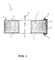
- FIG. 1 shows a schematic representation of a section through a device according to the invention according to an embodiment.
- the device 1 for transmitting electric current and / or signals in a motor vehicle has a coil spring cassette 2 and a film-like label 3 attached thereto.
- a label 3 is shown in the figures, the device 1 according to the invention can also comprise a plurality of labels which, for example, are distributed and mounted uniformly around the circumference of the coil spring cassette 2.
- the coil spring cassette 2 consists of a stator 4 and a rotor 5 which is rotatable relative to the stator 4 about the axis A of the coil spring cassette.
- winding space 6 at least line 7, for example, a FBL, housed, of which only a few turns are shown schematically.
- the line 7 is at one end to the stator 4 and at the other end to the rotor 5 in known manner connected.
- the coil spring cassette 2 is intended for installation in the steering wheel of the motor vehicle, wherein the rotor 5 with the steering wheel and thus relative to the vehicle-fixed stator 4 is rotatable.
- the film-like label 3 holds the coil spring cassette 2 in the mounting position for its installation in the steering wheel of the motor vehicle.
- the stator 4 and the rotor 5 of the coil spring cassette 2 are fixed to each other by the label 3 in a predetermined relative position.
- the label 3 is externally attached to the coil spring cassette 2 so as to extend over both the rotor 5 and the stator 4, as shown in FIG Fig. 1 shown.
- the label 3 is mechanically fixed both on the stator 4 and on the rotor 5.
- Attachment points 8 shown schematically can be realized, for example, by welding points, by clamping disks or by riveting each on the stator 4 and on the rotor 5.
- a thermoplastically deformable rivet bolt is used for this purpose. Due to the mechanical fixing the label 3 is permanently connected to the coil spring cassette 2 and thereby guarantees the mid-position fixation of the same during installation in the steering wheel.
- the label 3 may for example consist of polyethylene.
- the label 3 may further be coated on its back with adhesive, so that it can be glued to the coil spring cassette 2 in addition to the mechanical fixing on the stator 4 and the rotor 5.
- the width of the label 3 (perpendicular to the page in Fig. 1 ) Is such that stator 4 and rotor 5 are securely fixed in the mounting position without the label 3 tearing by mistake.
- the coil spring cassette 2 After installation of the coil spring cassette 2 in the steering wheel of the motor vehicle, the coil spring cassette 2 is brought into working position by the sheet-like label 3 is torn during the first rotational movement of the steering wheel, so that the stator 4 and the rotor 5 are rotatable relative to each other.
- the label 3 a predetermined breaking point 9, so that the label 3 in the rotational movement of the rotor 5 at the predetermined breaking point. 9 is torn.
- the predetermined breaking point 9 is preferably located in the immediate vicinity of the transition point between the stator 4 and rotor 5, as in Fig. 1 indicated, so that parts of the label 3 in the working position of the coil spring cassette 2, the rotation of the rotor 5 can not affect.
Landscapes
- Engineering & Computer Science (AREA)
- Mechanical Engineering (AREA)
- Connection Of Motors, Electrical Generators, Mechanical Devices, And The Like (AREA)
- Steering Controls (AREA)
Abstract
Description
- Die Erfindung bezieht sich auf eine Vorrichtung zur Übertragung von elektrischem Strom und/oder von Signalen in einem Kraftfahrzeug, welche eine aus einem Stator und einem Rotor bestehende Wickelfederkassette und mindestens ein Fixierelement aufweist, durch welches eine für den Einbau der Wickelfederkassette in das Lenkrad des Kraftfahrzeugs vorgegebene relative Position von Stator und Rotor zueinander fixiert ist. In der Wickelfederkassette ist mindestens eine in Windungen verlaufende Leitung angeordnet, die mit einem Ende mit dem Stator und mit dem anderen Ende mit dem Rotor verbunden ist.
- Wickelfedern werden heute bevorzugt in Kraftfahrzeugen verwendet, um elektrische oder optische Signale, beispielsweise zum Auslösen des Airbags im Lenkrad, zwischen feststehenden und beweglichen Fahrzeugteilen zu übertragen. Die Leitung kann elektrische und/oder optische Leitungen umfassen. Wickelfedern gewährleisten eine sichere und dauerhafte elektrische und/oder optische Verbindung. Als Wickelfeder wird eine Leitung bezeichnet, die innerhalb der Kassette entweder spiralförmig in konzentrischen Windungen um einen Kern in der Kassette aufgewickelt oder in einer Schlaufe geführt ist (letztere auch bezeichnet als Kurzband-Wickelfeder oder U-turn-Wickelfeder). Mit ihren beiden Enden verbindet die Leitung ein mit dem Lenkrad drehbares Bauteil (den Rotor) mit einem fahrzeugfesten Bauteil (dem Stator) elektrisch und/oder optisch miteinander. Wickelfedern erlauben eine relative Drehbewegung des Stators und des Rotors, ohne die sichere elektrische und/oder optische Verbindung zwischen fahrzeugfesten und lenkradfesten Fahrzeugteilen zu beeinträchtigen. Die Leitung kann beispielsweise eine flexible Flachbandleitung (FBL) sein, d.h. in Isoliermaterial mit Abstand zueinander eingebettete Leiterbahnen. Der Rotor und der Stator bilden zusammen ein die Leitung aufnehmendes Gehäuse, welches auch als Wickelfederkassette bezeichnet wird.
- Für den Einbau der Wickelfederkassette in das Lenkrad eines Kraftfahrzeugs ist es wichtig, daß die beiden Enden der FBL oder einer anderen Leitung eine bestimmte Position zueinander haben. Damit wird gewährleistet, daß die vorgegebenen Umdrehungen des Rotors in beide Drehrichtungen des Lenkrads vollzogen werden können, ohne daß die Leitung von der Kassette abreißt.
- Die
DE 42 16 526 A1 beschreibt eine in einer kreisförmigen Kassette untergebrachte, in Windungen verlaufende elektrische Leitung, wobei die Kassette aus einem um die Achse der Kassette drehbaren Rotor und einem Stator besteht. Um die beiden Teile während des Einbaus in das Lenkrad eines Kraftfahrzeugs in einer bestimmten Position zueinander zu halten, befindet sich am Rotor ein nach außen abstehender Ansatz zur Aufnahme einer Schraube und eine mittels der Schraube verstellbare Feder. Die Feder wird in Montageposition der Kassette in eine Vertiefung des Stators gedrückt, sodaß sich der Rotor unverdrehbar am Stator anliegt. In Arbeitsposition wird die Arretierung durch Lockern der Schraube aufgehoben. - Der Erfindung liegt die Aufgabe zugrunde, eine verbesserte Vorrichtung zur Übertragung von elektrischem Strom und/oder von Signalen in einem Kraftfahrzeug, welche eine aus einem Stator und einem Rotor bestehende Wickelfederkassette und mindestens ein Fixierelement aufweist, bereitzustellen, welche einfach, schnell und kostengünstig zu realisieren ist und bei welchem die Wickelfederkassettenteile sicher zueinander festgestellt werden.
- Diese Aufgabe wird gemäß der Erfindung dadurch gelöst,
- daß das Fixierelement ein folienartiges Etikett ist, das außen an der Wickelfederkassette angebracht ist und sich vom Rotor bis zum Stator erstreckt, und
- daß das Etikett sowohl am Stator als auch am Rotor mechanisch festgelegt ist.
- Die erfindungsgemäße Vorrichtung erlaubt das Fixieren von Stator und Rotor in der für den Einbau der Wickelfederkassette in das Lenkrad vorbestimmten Stellung zueinander. Mit dieser Montageposition bzw. Mittelstellung wird gewährleistet, daß die Leitung in Arbeitsposition nicht beschädigt oder anderweitig beeinträchtigt wird. Die Stellungsfixierung ist durch die unlösbaren mechanischen Verbindungen zwischen dem Etikett und dem Rotor bzw. dem Stator besonders sicher und auch über längere Lager- und Transportzeiten der Wickelfederkassette dauerhaft. Das folienartige Etikett ist ein im Handel erhältliches Element, welches im Vergleich zu anderen, maschinengefertigten Sicherungselementen relativ günstig ist. Die mechanische Festlegung des Etiketts am Stator und am Rotor kann automatisch erfolgen, beispielweise durch Nieten oder Schweißen, wodurch die erfindungsgemäße Vorrichtung auf besonders einfache Weise hergestellt werden kann. Das Etikett wird in Arbeitsposition nach dem Einbau der Wickelfederkassette bei der ersten Drehbewegung des Lenkrads und damit des Rotors zerrissen. Dabei verbleiben keine störenden Elemente, die die Funktion der Wickelfeder beeinträchtigen könnten.
- Die erfindungsgemäße Vorrichtung wird anhand der Zeichnung erläutert.
Fig. 1 zeigt in schematischer Darstellung einen Schnitt durch eine erfindungsgemäße Vorrichtung nach einem Ausführungsbeispiel. - Die Vorrichtung 1 zur Übertragung von elektrischem Strom und/oder Signalen in einem Kraftfahrzeug weist eine Wickelfederkassette 2 und ein an dieser angebrachtes, folienartiges Etikett 3 auf. Obwohl in den Abbildungen nur ein Etikett 3 dargestellt ist, kann die erfindungsgemäße Vorrichtung 1 auch mehrere Etiketten umfassen, die beispielsweise gleichmäßig um den Umfang der Wickelfederkassette 2 verteilt und angebracht sind.
- Die Wickelfederkassette 2 besteht aus einem Stator 4 und einem Rotor 5, der relativ zum Stator 4 um die Achse A der Wickelfederkassette drehbar ist. In dem durch den Stator 4 und den Rotor 5 begrenzten Wickelraum 6 ist mindestens Leitung 7, beispielsweise eine FBL, untergebracht, von der nur einige Windungen schematisch eingezeichnet sind. Die Leitung 7 ist mit einem Ende mit dem Stator 4 und mit dem anderen Ende mit dem Rotor 5 in bekannter Weise verbunden. Die Wickelfederkassette 2 ist für den Einbau in das Lenkrad des Kraftfahrzeugs bestimmt, wobei der Rotor 5 mit dem Lenkrad und damit relativ zu dem fahrzeugfesten Stator 4 drehbar ist.
- Das folienartige Etikett 3 hält die Wickelfederkassette 2 in Montageposition für ihren Einbau in das Lenkrad des Kraftfahrzeugs. In Montageposition werden der Stator 4 und der Rotor 5 der Wickelfederkassette 2 durch das Etikett 3 in einer vorgegebenen relativen Position zueinander fixiert. Das Etikett 3 ist außen derart an der Wickelfederkassette 2 angebracht, daß es sich sowohl über den Rotor 5 als auch den Stator 4 erstreckt, wie in
Fig. 1 dargestellt. Das Etikett 3 ist sowohl am Stator 4 als auch am Rotor 5 mechanisch festgelegt. Die inFig. 1 schematisch dargestellten Befestigungspunkte 8 können beispielsweise durch Schweißpunkte, durch Klemmscheiben oder durch Nieten jeweils am Stator 4 und am Rotor 5 realisiert werden. In einer bevorzugten Ausführungsform wird hierfür ein thermoplastisch verformbarer Nietbolzen verwendet. Durch die mechanische Festlegung ist das Etikett 3 unlösbar mit der Wickelfederkassette 2 verbunden und garantiert dadurch die Mittelstellungsfixierung derselben während des Einbaus in das Lenkrad. - Das Etikett 3 kann beispielsweise aus Polyethylen bestehen. Das Etikett 3 kann weiterhin auf seiner Rückseite mit Klebstoff beschichtet sein, sodaß es zusätzlich zu der mechanischen Festlegung am Stator 4 und am Rotor 5 an die Wickelfederkassette 2 geklebt werden kann. Die Breite des Etiketts 3 (senkrecht zur Blattebene in
Fig. 1 ) ist derart, daß Stator 4 und Rotor 5 in Montageposition sicher fixiert werden, ohne daß das Etikett 3 versehentlich zerreißt. - Nach dem Einbau der Wickelfederkassette 2 in das Lenkrad des Kraftfahrzeugs wird die Wickelfederkassette 2 in Arbeitsposition gebracht, indem das folienartige Etikett 3 während der ersten Drehbewegung des Lenkrads zerrissen wird, sodaß der Stator 4 und der Rotor 5 relativ zueinander drehbar sind. In der bevorzugten Ausführungsform der erfindungsgemäßen Vorrichtung 1 nach
Fig. 1 weist das Etikett 3 eine Sollbruchstelle 9 auf, sodaß das Etikett 3 bei der Rotationsbewegung des Rotors 5 an der Sollbruchstelle 9 zerrissen wird. Die Sollbruchstelle 9 befindet sich vorzugsweise in unmittelbarer Nähe der Übergangsstelle zwischen Stator 4 und Rotor 5, wie inFig. 1 angedeutet, sodaß Teile des Etiketts 3 in Arbeitsposition der Wickelfederkassette 2 die Rotation des Rotors 5 nicht beeinträchtigen können.
Claims (6)
- Vorrichtung (1) zur Übertragung von elektrischem Strom und/oder von Signalen in einem Kraftfahrzeug, welche eine aus einem Stator (4) und einem Rotor (5) bestehende Wickelfederkassette (2) aufweist, in welcher mindestens eine in Windungen verlaufende Leitung (7) angeordnet ist, die mit einem Ende mit dem Stator (4) und mit dem anderen Ende mit dem Rotor (5) verbunden ist, und welche mindestens ein Fixierelement (3) aufweist, durch welches eine für den Einbau der Wickelfederkassette (2) in das Lenkrad des Kraftfahrzeugs vorgegebene relative Position von Stator (4) und Rotor (5) zueinander fixiert ist, dadurch gekennzeichnet,- daß das Fixierelement ein folienartiges Etikett (3) ist, das außen an der Wickelfederkassette (2) angebracht ist und sich vom Rotor (5) bis zum Stator (4) erstreckt, und- daß das Etikett (3) sowohl am Stator (4) als auch am Rotor (5) mechanisch festgelegt ist.
- Vorrichtung (1) nach Anspruch 1, dadurch gekennzeichnet, daß das Etikett (3) zusätzlich an die Wickelfederkassette (2) geklebt ist.
- Vorrichtung (1) nach Anspruch 1 oder 2, dadurch gekennzeichnet, daß das Etikett (3) durch Schweißpunkte mechanisch am Stator (4) und am Rotor (5) festgelegt ist.
- Vorrichtung (1) nach Anspruch 1 oder 2, dadurch gekennzeichnet, daß das Etikett (3) durch Nieten mechanisch am Stator (4) und am Rotor (5) festgelegt ist.
- Vorrichtung (1) nach Anspruch 1 oder 2, dadurch gekennzeichnet, daß das Etikett (3) durch Klemmscheiben mechanisch am Stator (4) und am Rotor (5) festgelegt ist.
- Vorrichtung (1) nach einem der vorangehenden Ansprüche, dadurch gekennzeichnet, daß das Etikett (3) eine Sollbruchstelle (9) aufweist, sodaß das Etikett (3) bei der Rotationsbewegung des Rotors (5) an der Sollbruchstelle (9) zerrissen wird.
Priority Applications (2)
| Application Number | Priority Date | Filing Date | Title |
|---|---|---|---|
| EP14305216.5A EP2907701B1 (de) | 2014-02-18 | 2014-02-18 | Vorrichtung zur Übertragung von elektrischem Strom und/oder Signalen in einem Kraftfahrzeug |
| US14/619,473 US9827927B2 (en) | 2014-02-18 | 2015-02-11 | Device for transmitting electrical current and/or signals in a motor vehicle |
Applications Claiming Priority (1)
| Application Number | Priority Date | Filing Date | Title |
|---|---|---|---|
| EP14305216.5A EP2907701B1 (de) | 2014-02-18 | 2014-02-18 | Vorrichtung zur Übertragung von elektrischem Strom und/oder Signalen in einem Kraftfahrzeug |
Publications (2)
| Publication Number | Publication Date |
|---|---|
| EP2907701A1 true EP2907701A1 (de) | 2015-08-19 |
| EP2907701B1 EP2907701B1 (de) | 2016-05-25 |
Family
ID=50193415
Family Applications (1)
| Application Number | Title | Priority Date | Filing Date |
|---|---|---|---|
| EP14305216.5A Active EP2907701B1 (de) | 2014-02-18 | 2014-02-18 | Vorrichtung zur Übertragung von elektrischem Strom und/oder Signalen in einem Kraftfahrzeug |
Country Status (2)
| Country | Link |
|---|---|
| US (1) | US9827927B2 (de) |
| EP (1) | EP2907701B1 (de) |
Cited By (1)
| Publication number | Priority date | Publication date | Assignee | Title |
|---|---|---|---|---|
| WO2022218760A1 (de) * | 2021-04-14 | 2022-10-20 | Kostal Automobil Elektrik Gmbh & Co. Kg | Wickelfederkassette |
Citations (4)
| Publication number | Priority date | Publication date | Assignee | Title |
|---|---|---|---|---|
| JPH02138889U (de) * | 1989-04-25 | 1990-11-20 | ||
| DE4216526A1 (de) | 1992-05-19 | 1993-11-25 | Kabelmetal Electro Gmbh | Vorrichtung zur Signalübertragung zwischen zwei relativ zueinander bewegbaren Endstellen |
| JPH0917541A (ja) * | 1995-06-26 | 1997-01-17 | Alps Electric Co Ltd | 回転コネクタ |
| JPH09171870A (ja) * | 1995-12-19 | 1997-06-30 | Toyoda Gosei Co Ltd | ブラシレス継電器 |
Family Cites Families (2)
| Publication number | Priority date | Publication date | Assignee | Title |
|---|---|---|---|---|
| JPH02138889A (ja) | 1988-11-18 | 1990-05-28 | Matsushita Electric Ind Co Ltd | 超音波送受波器 |
| US20100143101A1 (en) * | 2008-12-05 | 2010-06-10 | General Electric Company | Compliant foil seal for rotary machines |
-
2014
- 2014-02-18 EP EP14305216.5A patent/EP2907701B1/de active Active
-
2015
- 2015-02-11 US US14/619,473 patent/US9827927B2/en not_active Expired - Fee Related
Patent Citations (4)
| Publication number | Priority date | Publication date | Assignee | Title |
|---|---|---|---|---|
| JPH02138889U (de) * | 1989-04-25 | 1990-11-20 | ||
| DE4216526A1 (de) | 1992-05-19 | 1993-11-25 | Kabelmetal Electro Gmbh | Vorrichtung zur Signalübertragung zwischen zwei relativ zueinander bewegbaren Endstellen |
| JPH0917541A (ja) * | 1995-06-26 | 1997-01-17 | Alps Electric Co Ltd | 回転コネクタ |
| JPH09171870A (ja) * | 1995-12-19 | 1997-06-30 | Toyoda Gosei Co Ltd | ブラシレス継電器 |
Cited By (2)
| Publication number | Priority date | Publication date | Assignee | Title |
|---|---|---|---|---|
| WO2022218760A1 (de) * | 2021-04-14 | 2022-10-20 | Kostal Automobil Elektrik Gmbh & Co. Kg | Wickelfederkassette |
| DE102021001962A1 (de) | 2021-04-14 | 2022-10-20 | Kostal Automobil Elektrik Gmbh & Co. Kg | Wickelfederkassette |
Also Published As
| Publication number | Publication date |
|---|---|
| US9827927B2 (en) | 2017-11-28 |
| US20150232046A1 (en) | 2015-08-20 |
| EP2907701B1 (de) | 2016-05-25 |
Similar Documents
| Publication | Publication Date | Title |
|---|---|---|
| DE102007044230B4 (de) | Drehmelder und bürstenfreier Motor | |
| EP0417350B1 (de) | Stromleitungsverbinder zur Überbrückung von Leiterunterbrechungen zwischen gegeneinander drehbaren Teilen | |
| EP3383709B1 (de) | Kabelführungseinrichtung für anschlusskabel eines gassackmoduls, verkabelung, gassackmodul sowie lenkrad oder fahrzeug mit einer derartigen kabelführungseinrichtung | |
| DE3541287C2 (de) | ||
| EP3181431A1 (de) | Drehmomentsensorvorrichtung und kraftfahrzeug mit einer solchen drehmomentsensorvorrichtung | |
| DE3732124A1 (de) | Vorrichtung zur stromuebertragung zwischen zwei relativ zueinander bewegbaren kontaktstellen | |
| DE10342062B4 (de) | Lenkraddrehverbinder | |
| EP0425846B1 (de) | Vorrichtung zur Stromübertragung zwischen zwei Endstellen | |
| DE102010063726A1 (de) | Kontakteinrichtung in einem Stator einer elektrischen Maschine | |
| DE4216526A1 (de) | Vorrichtung zur Signalübertragung zwischen zwei relativ zueinander bewegbaren Endstellen | |
| DE69401702T2 (de) | Drehkontaktor insbesondere für kraftfahrzeuge | |
| EP2907701B1 (de) | Vorrichtung zur Übertragung von elektrischem Strom und/oder Signalen in einem Kraftfahrzeug | |
| EP0387585B1 (de) | Flacchkabelspirale | |
| WO2008065183A1 (de) | Wickelfederkassette | |
| DE102007054952B4 (de) | Wickelfeder | |
| DE102010047160A1 (de) | Anordnung zur Befestigung einer Vibrationseinheit an einem Lenkrad | |
| EP1800956B1 (de) | Vorrichtung zur Signal- bzw. Stromübertragung zwischen Endstellen | |
| EP0563789B1 (de) | Vorrichtung zur Signalübertragung zwischen zwei relativ zueinander bewegbaren Endstellen | |
| EP1324435B1 (de) | Elektrischer Verbinder zwischen zwei Endstellen | |
| DE19537628A1 (de) | Vorrichtung zum Übertragen von Signalen | |
| EP0693806B1 (de) | Vorrichtung zur Signalübertragung zwischen zwei Endstellen | |
| EP1800957B1 (de) | Vorrichtung zur Signal- bzw. Stromübertragung zwischen Endstellen | |
| DE2444424C3 (de) | Stromabnehmer-System für eine Kabine einer Drahtseilbahn | |
| EP0803406B1 (de) | Vorrichtung zur Signalübertragung zwischen zwei Endstellen | |
| DE4122248A1 (de) | Kreuzspul-anzeigeinstrument |
Legal Events
| Date | Code | Title | Description |
|---|---|---|---|
| PUAI | Public reference made under article 153(3) epc to a published international application that has entered the european phase |
Free format text: ORIGINAL CODE: 0009012 |
|
| 17P | Request for examination filed |
Effective date: 20150602 |
|
| AK | Designated contracting states |
Kind code of ref document: A1 Designated state(s): AL AT BE BG CH CY CZ DE DK EE ES FI FR GB GR HR HU IE IS IT LI LT LU LV MC MK MT NL NO PL PT RO RS SE SI SK SM TR |
|
| AX | Request for extension of the european patent |
Extension state: BA ME |
|
| 17Q | First examination report despatched |
Effective date: 20150929 |
|
| GRAP | Despatch of communication of intention to grant a patent |
Free format text: ORIGINAL CODE: EPIDOSNIGR1 |
|
| INTG | Intention to grant announced |
Effective date: 20151130 |
|
| GRAS | Grant fee paid |
Free format text: ORIGINAL CODE: EPIDOSNIGR3 |
|
| GRAA | (expected) grant |
Free format text: ORIGINAL CODE: 0009210 |
|
| AK | Designated contracting states |
Kind code of ref document: B1 Designated state(s): AL AT BE BG CH CY CZ DE DK EE ES FI FR GB GR HR HU IE IS IT LI LT LU LV MC MK MT NL NO PL PT RO RS SE SI SK SM TR |
|
| REG | Reference to a national code |
Ref country code: GB Ref legal event code: FG4D Free format text: NOT ENGLISH |
|
| REG | Reference to a national code |
Ref country code: CH Ref legal event code: EP |
|
| REG | Reference to a national code |
Ref country code: AT Ref legal event code: REF Ref document number: 802009 Country of ref document: AT Kind code of ref document: T Effective date: 20160615 Ref country code: IE Ref legal event code: FG4D Free format text: LANGUAGE OF EP DOCUMENT: GERMAN |
|
| REG | Reference to a national code |
Ref country code: DE Ref legal event code: R096 Ref document number: 502014000855 Country of ref document: DE |
|
| REG | Reference to a national code |
Ref country code: SE Ref legal event code: TRGR |
|
| REG | Reference to a national code |
Ref country code: LT Ref legal event code: MG4D |
|
| REG | Reference to a national code |
Ref country code: NL Ref legal event code: MP Effective date: 20160525 |
|
| PG25 | Lapsed in a contracting state [announced via postgrant information from national office to epo] |
Ref country code: NO Free format text: LAPSE BECAUSE OF FAILURE TO SUBMIT A TRANSLATION OF THE DESCRIPTION OR TO PAY THE FEE WITHIN THE PRESCRIBED TIME-LIMIT Effective date: 20160825 Ref country code: FI Free format text: LAPSE BECAUSE OF FAILURE TO SUBMIT A TRANSLATION OF THE DESCRIPTION OR TO PAY THE FEE WITHIN THE PRESCRIBED TIME-LIMIT Effective date: 20160525 Ref country code: NL Free format text: LAPSE BECAUSE OF FAILURE TO SUBMIT A TRANSLATION OF THE DESCRIPTION OR TO PAY THE FEE WITHIN THE PRESCRIBED TIME-LIMIT Effective date: 20160525 Ref country code: LT Free format text: LAPSE BECAUSE OF FAILURE TO SUBMIT A TRANSLATION OF THE DESCRIPTION OR TO PAY THE FEE WITHIN THE PRESCRIBED TIME-LIMIT Effective date: 20160525 |
|
| PG25 | Lapsed in a contracting state [announced via postgrant information from national office to epo] |
Ref country code: ES Free format text: LAPSE BECAUSE OF FAILURE TO SUBMIT A TRANSLATION OF THE DESCRIPTION OR TO PAY THE FEE WITHIN THE PRESCRIBED TIME-LIMIT Effective date: 20160525 Ref country code: LV Free format text: LAPSE BECAUSE OF FAILURE TO SUBMIT A TRANSLATION OF THE DESCRIPTION OR TO PAY THE FEE WITHIN THE PRESCRIBED TIME-LIMIT Effective date: 20160525 Ref country code: PT Free format text: LAPSE BECAUSE OF FAILURE TO SUBMIT A TRANSLATION OF THE DESCRIPTION OR TO PAY THE FEE WITHIN THE PRESCRIBED TIME-LIMIT Effective date: 20160926 Ref country code: RS Free format text: LAPSE BECAUSE OF FAILURE TO SUBMIT A TRANSLATION OF THE DESCRIPTION OR TO PAY THE FEE WITHIN THE PRESCRIBED TIME-LIMIT Effective date: 20160525 Ref country code: GR Free format text: LAPSE BECAUSE OF FAILURE TO SUBMIT A TRANSLATION OF THE DESCRIPTION OR TO PAY THE FEE WITHIN THE PRESCRIBED TIME-LIMIT Effective date: 20160826 |
|
| PG25 | Lapsed in a contracting state [announced via postgrant information from national office to epo] |
Ref country code: CZ Free format text: LAPSE BECAUSE OF FAILURE TO SUBMIT A TRANSLATION OF THE DESCRIPTION OR TO PAY THE FEE WITHIN THE PRESCRIBED TIME-LIMIT Effective date: 20160525 Ref country code: SK Free format text: LAPSE BECAUSE OF FAILURE TO SUBMIT A TRANSLATION OF THE DESCRIPTION OR TO PAY THE FEE WITHIN THE PRESCRIBED TIME-LIMIT Effective date: 20160525 Ref country code: RO Free format text: LAPSE BECAUSE OF FAILURE TO SUBMIT A TRANSLATION OF THE DESCRIPTION OR TO PAY THE FEE WITHIN THE PRESCRIBED TIME-LIMIT Effective date: 20160525 Ref country code: EE Free format text: LAPSE BECAUSE OF FAILURE TO SUBMIT A TRANSLATION OF THE DESCRIPTION OR TO PAY THE FEE WITHIN THE PRESCRIBED TIME-LIMIT Effective date: 20160525 Ref country code: DK Free format text: LAPSE BECAUSE OF FAILURE TO SUBMIT A TRANSLATION OF THE DESCRIPTION OR TO PAY THE FEE WITHIN THE PRESCRIBED TIME-LIMIT Effective date: 20160525 |
|
| REG | Reference to a national code |
Ref country code: FR Ref legal event code: PLFP Year of fee payment: 4 |
|
| PG25 | Lapsed in a contracting state [announced via postgrant information from national office to epo] |
Ref country code: PL Free format text: LAPSE BECAUSE OF FAILURE TO SUBMIT A TRANSLATION OF THE DESCRIPTION OR TO PAY THE FEE WITHIN THE PRESCRIBED TIME-LIMIT Effective date: 20160525 Ref country code: SM Free format text: LAPSE BECAUSE OF FAILURE TO SUBMIT A TRANSLATION OF THE DESCRIPTION OR TO PAY THE FEE WITHIN THE PRESCRIBED TIME-LIMIT Effective date: 20160525 |
|
| REG | Reference to a national code |
Ref country code: DE Ref legal event code: R097 Ref document number: 502014000855 Country of ref document: DE |
|
| PLBE | No opposition filed within time limit |
Free format text: ORIGINAL CODE: 0009261 |
|
| STAA | Information on the status of an ep patent application or granted ep patent |
Free format text: STATUS: NO OPPOSITION FILED WITHIN TIME LIMIT |
|
| 26N | No opposition filed |
Effective date: 20170228 |
|
| PG25 | Lapsed in a contracting state [announced via postgrant information from national office to epo] |
Ref country code: SI Free format text: LAPSE BECAUSE OF FAILURE TO SUBMIT A TRANSLATION OF THE DESCRIPTION OR TO PAY THE FEE WITHIN THE PRESCRIBED TIME-LIMIT Effective date: 20160525 Ref country code: BE Free format text: LAPSE BECAUSE OF NON-PAYMENT OF DUE FEES Effective date: 20170228 |
|
| PG25 | Lapsed in a contracting state [announced via postgrant information from national office to epo] |
Ref country code: MC Free format text: LAPSE BECAUSE OF FAILURE TO SUBMIT A TRANSLATION OF THE DESCRIPTION OR TO PAY THE FEE WITHIN THE PRESCRIBED TIME-LIMIT Effective date: 20160525 |
|
| REG | Reference to a national code |
Ref country code: CH Ref legal event code: PL |
|
| PG25 | Lapsed in a contracting state [announced via postgrant information from national office to epo] |
Ref country code: LI Free format text: LAPSE BECAUSE OF NON-PAYMENT OF DUE FEES Effective date: 20170228 Ref country code: CH Free format text: LAPSE BECAUSE OF NON-PAYMENT OF DUE FEES Effective date: 20170228 |
|
| REG | Reference to a national code |
Ref country code: IE Ref legal event code: MM4A |
|
| PG25 | Lapsed in a contracting state [announced via postgrant information from national office to epo] |
Ref country code: LU Free format text: LAPSE BECAUSE OF NON-PAYMENT OF DUE FEES Effective date: 20170218 |
|
| REG | Reference to a national code |
Ref country code: BE Ref legal event code: MM Effective date: 20170228 |
|
| REG | Reference to a national code |
Ref country code: FR Ref legal event code: PLFP Year of fee payment: 5 |
|
| PG25 | Lapsed in a contracting state [announced via postgrant information from national office to epo] |
Ref country code: IE Free format text: LAPSE BECAUSE OF NON-PAYMENT OF DUE FEES Effective date: 20170218 |
|
| PG25 | Lapsed in a contracting state [announced via postgrant information from national office to epo] |
Ref country code: MT Free format text: LAPSE BECAUSE OF FAILURE TO SUBMIT A TRANSLATION OF THE DESCRIPTION OR TO PAY THE FEE WITHIN THE PRESCRIBED TIME-LIMIT Effective date: 20160525 |
|
| GBPC | Gb: european patent ceased through non-payment of renewal fee |
Effective date: 20180218 |
|
| PG25 | Lapsed in a contracting state [announced via postgrant information from national office to epo] |
Ref country code: AL Free format text: LAPSE BECAUSE OF FAILURE TO SUBMIT A TRANSLATION OF THE DESCRIPTION OR TO PAY THE FEE WITHIN THE PRESCRIBED TIME-LIMIT Effective date: 20160525 |
|
| PG25 | Lapsed in a contracting state [announced via postgrant information from national office to epo] |
Ref country code: GB Free format text: LAPSE BECAUSE OF NON-PAYMENT OF DUE FEES Effective date: 20180218 |
|
| PG25 | Lapsed in a contracting state [announced via postgrant information from national office to epo] |
Ref country code: HU Free format text: LAPSE BECAUSE OF FAILURE TO SUBMIT A TRANSLATION OF THE DESCRIPTION OR TO PAY THE FEE WITHIN THE PRESCRIBED TIME-LIMIT; INVALID AB INITIO Effective date: 20140218 |
|
| PG25 | Lapsed in a contracting state [announced via postgrant information from national office to epo] |
Ref country code: BG Free format text: LAPSE BECAUSE OF FAILURE TO SUBMIT A TRANSLATION OF THE DESCRIPTION OR TO PAY THE FEE WITHIN THE PRESCRIBED TIME-LIMIT Effective date: 20160525 |
|
| PG25 | Lapsed in a contracting state [announced via postgrant information from national office to epo] |
Ref country code: CY Free format text: LAPSE BECAUSE OF FAILURE TO SUBMIT A TRANSLATION OF THE DESCRIPTION OR TO PAY THE FEE WITHIN THE PRESCRIBED TIME-LIMIT Effective date: 20160525 |
|
| PG25 | Lapsed in a contracting state [announced via postgrant information from national office to epo] |
Ref country code: MK Free format text: LAPSE BECAUSE OF FAILURE TO SUBMIT A TRANSLATION OF THE DESCRIPTION OR TO PAY THE FEE WITHIN THE PRESCRIBED TIME-LIMIT Effective date: 20160525 |
|
| REG | Reference to a national code |
Ref country code: AT Ref legal event code: MM01 Ref document number: 802009 Country of ref document: AT Kind code of ref document: T Effective date: 20190218 |
|
| PG25 | Lapsed in a contracting state [announced via postgrant information from national office to epo] |
Ref country code: AT Free format text: LAPSE BECAUSE OF NON-PAYMENT OF DUE FEES Effective date: 20190218 |
|
| PGFP | Annual fee paid to national office [announced via postgrant information from national office to epo] |
Ref country code: SE Payment date: 20200220 Year of fee payment: 7 |
|
| PG25 | Lapsed in a contracting state [announced via postgrant information from national office to epo] |
Ref country code: HR Free format text: LAPSE BECAUSE OF FAILURE TO SUBMIT A TRANSLATION OF THE DESCRIPTION OR TO PAY THE FEE WITHIN THE PRESCRIBED TIME-LIMIT Effective date: 20160525 |
|
| PG25 | Lapsed in a contracting state [announced via postgrant information from national office to epo] |
Ref country code: IS Free format text: LAPSE BECAUSE OF FAILURE TO SUBMIT A TRANSLATION OF THE DESCRIPTION OR TO PAY THE FEE WITHIN THE PRESCRIBED TIME-LIMIT Effective date: 20160925 |
|
| REG | Reference to a national code |
Ref country code: SE Ref legal event code: EUG |
|
| PG25 | Lapsed in a contracting state [announced via postgrant information from national office to epo] |
Ref country code: SE Free format text: LAPSE BECAUSE OF NON-PAYMENT OF DUE FEES Effective date: 20210219 |
|
| PGFP | Annual fee paid to national office [announced via postgrant information from national office to epo] |
Ref country code: DE Payment date: 20240219 Year of fee payment: 11 |
|
| PGFP | Annual fee paid to national office [announced via postgrant information from national office to epo] |
Ref country code: TR Payment date: 20240210 Year of fee payment: 11 Ref country code: IT Payment date: 20240228 Year of fee payment: 11 Ref country code: FR Payment date: 20240221 Year of fee payment: 11 |