EP2907699A2 - Kraftfahrzeug - Google Patents
Kraftfahrzeug Download PDFInfo
- Publication number
- EP2907699A2 EP2907699A2 EP14003615.3A EP14003615A EP2907699A2 EP 2907699 A2 EP2907699 A2 EP 2907699A2 EP 14003615 A EP14003615 A EP 14003615A EP 2907699 A2 EP2907699 A2 EP 2907699A2
- Authority
- EP
- European Patent Office
- Prior art keywords
- obstacle
- vehicle
- motor vehicle
- light
- light signal
- Prior art date
- Legal status (The legal status is an assumption and is not a legal conclusion. Google has not performed a legal analysis and makes no representation as to the accuracy of the status listed.)
- Granted
Links
Images


Classifications
-
- B—PERFORMING OPERATIONS; TRANSPORTING
- B60—VEHICLES IN GENERAL
- B60Q—ARRANGEMENT OF SIGNALLING OR LIGHTING DEVICES, THE MOUNTING OR SUPPORTING THEREOF OR CIRCUITS THEREFOR, FOR VEHICLES IN GENERAL
- B60Q1/00—Arrangement of optical signalling or lighting devices, the mounting or supporting thereof or circuits therefor
- B60Q1/26—Arrangement of optical signalling or lighting devices, the mounting or supporting thereof or circuits therefor the devices being primarily intended to indicate the vehicle, or parts thereof, or to give signals, to other traffic
- B60Q1/50—Arrangement of optical signalling or lighting devices, the mounting or supporting thereof or circuits therefor the devices being primarily intended to indicate the vehicle, or parts thereof, or to give signals, to other traffic for indicating other intentions or conditions, e.g. request for waiting or overtaking
- B60Q1/506—Arrangement of optical signalling or lighting devices, the mounting or supporting thereof or circuits therefor the devices being primarily intended to indicate the vehicle, or parts thereof, or to give signals, to other traffic for indicating other intentions or conditions, e.g. request for waiting or overtaking specific to silent vehicles, e.g. for warning that a hybrid or electric vehicle is approaching
-
- B—PERFORMING OPERATIONS; TRANSPORTING
- B60—VEHICLES IN GENERAL
- B60Q—ARRANGEMENT OF SIGNALLING OR LIGHTING DEVICES, THE MOUNTING OR SUPPORTING THEREOF OR CIRCUITS THEREFOR, FOR VEHICLES IN GENERAL
- B60Q1/00—Arrangement of optical signalling or lighting devices, the mounting or supporting thereof or circuits therefor
- B60Q1/26—Arrangement of optical signalling or lighting devices, the mounting or supporting thereof or circuits therefor the devices being primarily intended to indicate the vehicle, or parts thereof, or to give signals, to other traffic
- B60Q1/50—Arrangement of optical signalling or lighting devices, the mounting or supporting thereof or circuits therefor the devices being primarily intended to indicate the vehicle, or parts thereof, or to give signals, to other traffic for indicating other intentions or conditions, e.g. request for waiting or overtaking
- B60Q1/525—Arrangement of optical signalling or lighting devices, the mounting or supporting thereof or circuits therefor the devices being primarily intended to indicate the vehicle, or parts thereof, or to give signals, to other traffic for indicating other intentions or conditions, e.g. request for waiting or overtaking automatically indicating risk of collision between vehicles in traffic or with pedestrians, e.g. after risk assessment using the vehicle sensor data
- B60Q1/535—Arrangement of optical signalling or lighting devices, the mounting or supporting thereof or circuits therefor the devices being primarily intended to indicate the vehicle, or parts thereof, or to give signals, to other traffic for indicating other intentions or conditions, e.g. request for waiting or overtaking automatically indicating risk of collision between vehicles in traffic or with pedestrians, e.g. after risk assessment using the vehicle sensor data to prevent rear-end collisions, e.g. by indicating safety distance at the rear of the vehicle
-
- B—PERFORMING OPERATIONS; TRANSPORTING
- B60—VEHICLES IN GENERAL
- B60Q—ARRANGEMENT OF SIGNALLING OR LIGHTING DEVICES, THE MOUNTING OR SUPPORTING THEREOF OR CIRCUITS THEREFOR, FOR VEHICLES IN GENERAL
- B60Q9/00—Arrangement or adaptation of signal devices not provided for in one of main groups B60Q1/00 - B60Q7/00, e.g. haptic signalling
- B60Q9/002—Arrangement or adaptation of signal devices not provided for in one of main groups B60Q1/00 - B60Q7/00, e.g. haptic signalling for parking purposes, e.g. for warning the driver that his vehicle has contacted or is about to contact an obstacle
- B60Q9/007—Arrangement or adaptation of signal devices not provided for in one of main groups B60Q1/00 - B60Q7/00, e.g. haptic signalling for parking purposes, e.g. for warning the driver that his vehicle has contacted or is about to contact an obstacle providing information about the distance to an obstacle, e.g. varying sound
Definitions
- Modern motor vehicles often have a driver assistance system that supports the parking operation, whether forward or backward, by detecting potential obstacles in the vicinity of the vehicle, be it stationary obstacles, be they persons, with suitable sensors such as ultrasonic sensors or the like. If the vehicle is in a reverse parking process and if, for example, the ultrasound sensors installed on the rear side detect an obstacle that lies within the detection range, the distance to the obstacle is determined via the associated control device of the driver assistance system. When a minimum distance is reached, the driver inside the vehicle is given an audible or visual indication that indicates the potential obstacle. Frequently, beeps are used in this case, but also individual light point representations, which can be from the audio frequency or the light spot color of the distance, which can indeed reduce after the gift of the first display, yes recognize.
- the detected obstacle is a person standing on the side of the road, it is not always certain that the person is standing approximate vehicle recorded. This is due to the fact that modern motor vehicles are very quiet, that is, the person does not always perceive the engine noise, even when ambient noise is present. In the case of hybrid or electric vehicles are often heard no road noise, so here the risk is even greater that a person does not notice an approaching car at all.
- the invention is therefore based on the problem of specifying a motor vehicle with improved warning possibility.
- a light signal is gebbar, which is visible at least outside the vehicle.
- an active warning is provided outside the vehicle of persons who are detected as an obstacle, this warning information being given when the vehicle has taken a minimum distance to the detected person, and naturally with increasing approach.
- This light signal it is possible that the person becomes aware of the approaching vehicle, so that the person can step out of the path of movement of the vehicle and the obstacle is no longer detected as such.
- the light signal which is preferably in the form of a plurality of consecutively following light pulses can be given, which are given by means of a suitable lighting device, should have the highest possible light intensity, so that it is clearly detected even during the day.
- a corresponding colored light signal for example a red light signal, which is usually also perceived as a warning color.
- the light signal with the use of said lighting devices with a comparison with the normal operation of the lighting device increased light intensity is gebbar.
- the brake light or the turn signal etc. will therefore be much brighter if the warning signal is given than in normal operation when the driver operates the brake pedal or the turn signal. This can also be given by day a very noticeable, bright respectively even bright light signal that the person, so the obstacle is such, can easily detect.
- the driver assistance system is also able to give a corresponding warning signal in the vehicle interior, be it acoustically, optically or in both forms.
- warning signals can be given both inside the vehicle and outside the vehicle.
- the device for generating an audible or visual, detectable in the vehicle interior warning signal upon detection of a first minimum distance to the obstacle and the gift of the light signal formed only upon detection of a second, shorter minimum distance is.
- the driver may first receive warning information on the vehicle interior, such as a relatively low frequency or lower volume beep, or equivalent optical display representation, etc.
- An external warning signal is not given in this case, since the distance of 1.5 m is still considerably large and it can be assumed that the person, if a person represents the obstacle, certainly still capture the vehicle can.
- the warning tone sequence given inside the vehicle becomes faster or louder, and the visual display also changes accordingly. An external warning signal is still not available.
- Fig. 1 shows a schematic diagram of a motor vehicle 1 according to the invention, comprising front headlights 2, front turn signal 3, taillights 4, brake lights 5 and rear turn signal 6. All are built from the house on the vehicle lighting devices.
- a driver assistance system 7 which serves to detect obstacle information from the surroundings in order to warn the driver in the event of a detected obstacle, but also persons located outside.
- This driver assistance system 7 comprises, on the one hand, a control device 8, as well as a plurality of front-mounted sensors 9, for example ultrasound sensors, as well as rear-mounted sensors, likewise, for example, ultrasonic sensors 10. All sensors 9, 10 communicate with the control device 8. The sensors serve to detect a possible obstacle capture, wherein the control device based on the sensor signals is able to calculate an actual distance of the vehicle or a defined vehicle edge or surface to the obstacle.
- the control device 8 also has control access to all of the aforementioned lighting devices (front headlights 2, indicators 3, taillights 4, brake lights 5, turn signals 6), that is, can control them individually. About one or more of these lighting fixtures is, optionally spatially resolved, in the case of detection of an obstacle and reaching a sufficient minimum distance, a light signal given as a warning signal to the outside.
- the control device 8 communicates with other control devices that serve to control the corresponding lighting devices.
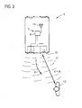
- the Figures 2-4 show three different situations, as they are typical for a reverse parking operation.
- the motor vehicle 1 Shown is the motor vehicle 1 according to the invention, which moves backwards, as shown by the arrow P.
- the driver assistance system 7 With engagement of the reverse gear, the driver assistance system 7 is activated as a rule, so that the rear-mounted ultrasonic sensors 10 send out their transmission signals 11, which are used for obstacle detection.
- Corresponding reflection signals are detected by the ultrasonic sensors 10 and evaluated by the control device 8 in order to detect a possible obstacle or to determine the distance.
- the monitoring area detected via the transmission signals 11 is an obstacle in the form of a person 12.
- This obstacle 12 is still sufficiently far away from the vehicle 1 after the detected actual distance d is greater than a first minimum distance d 1 , as in FIG Fig. 2 is shown (d> d 1 ). Due to the still large distance, an imminent danger situation is not yet given.
- the actual distance d in this situation is even greater than a second minimum distance d 2 (d> d 2 ).
- This minimum distance d 2 defines a distance from the motor vehicle to the obstacle, with the achievement of which a second warning information in the form of a light signal which is radiated outwards in the direction of the obstacle 12 is given. This situation has not yet been reached after the minimum distance d 2 has not yet been taken.
- direction-selective warning signal input by controlling the brake light located on this side of the vehicle (alternatively, the turn signal 6 could also be actuated on this side, or the tail light 4, as well as a plurality of light devices 4, 5 located on this side, 6 can be controlled).
- the brake light 5 is preferably driven so that it emits a significantly higher light intensity for the administration of the light signal 14, as in normal operation, when the driver steps on the brake pedal.
- this light signal now has the obstacle 12, as I said a person, the ability to capture the approaching vehicle.
- the vehicle is already relatively close, for example, the second minimum distance d 2 is 50 cm.
- the person 12 has not become aware of the vehicle 1, since, according to the situation, according to Fig. 2 , according to the situation Fig. 4 did not move.
- the person can now detect the vehicle and step aside, so that an accident hazard is avoided.
- the driver is continuously informed of the increasing approach to the obstacle via the signaling device 13, so that the driver can also react accordingly. If he continues his journey, for example, shortly after reaching the second minimum distance d 2, he is given an aggressive continuous warning tone in order to draw his attention to the remaining obstacle.
- This is also sufficient after it is generally assumed that a person detects an approaching motor vehicle and steps aside in time. However, this is not always the case, not least because of the low engine noise or lack of engine noise in the case of electric vehicles.
- the motor vehicle according to the invention or the driver assistance system 7 designed according to the invention which is able to emit the light signal to the outside, a warning is possible.
Landscapes
- Engineering & Computer Science (AREA)
- Mechanical Engineering (AREA)
- Transportation (AREA)
- Human Computer Interaction (AREA)
- Lighting Device Outwards From Vehicle And Optical Signal (AREA)
- Optical Radar Systems And Details Thereof (AREA)
- Traffic Control Systems (AREA)
Abstract
Description
- Die Erfindung betrifft ein Kraftfahrzeug, umfassend eine Einrichtung zur Erfassung eines Abstands zu einem in der Nähe des Fahrzeugs befindlichen Hindernis sowie zur Ausgabe einer Warninformation bei Erreichen eines definierten Mindestabstands zu dem Hindernis.
- Moderne Kraftfahrzeuge verfügen häufig über ein Fahrerassistenzsystem, das den Einparkvorgang, sei es vorwärts oder rückwärts, unterstützt, indem potentielle, im Umfeld des Fahrzeugs befindliche Hindernisse, seien es stehende Hindernisse, seien es Personen, mit geeigneten Sensoren wie Ultraschallsensoren oder dergleichen erfasst werden. Befindet sich das Fahrzeug in einem Rückwärtseinparkvorgang und sensieren beispielsweise die heckseitig verbauten Ultraschallsensoren ein Hindernis, das im Erfassungsbereich liegt, so wird über die zugeordnete Steuerungseinrichtung des Fahrerassistenzsystems der Abstand zu dem Hindernis ermittelt. Mit Erreichen eines Mindestabstands wird dem Fahrer im Fahrzeuginneren eine akustische oder optische Anzeige gegeben, die ihn auf das potentielle Hindernis hinweist. Häufig werden dabei Piepstöne dabei verwendet, aber auch einzelne Lichtpunktdarstellungen, wobei sich aus der Tonfrequenz respektive der Lichtpunktfarbe der Abstand, der sich nach Gabe der ersten Anzeige ja weiter verringern kann, erkennen lässt.
- Für den Fahrer ist also eine eindeutige Erfassungsmöglichkeit gegeben, ein etwaiges Hindernis zu erkennen, so dass er rechtzeitig entsprechende Maßnahmen ergreifen kann, indem er rechtzeitig bremst respektive den Einparkvorgang abbricht und rangiert etc.
- Handelt es sich bei dem erfassten Hindernis um eine Person die am Straßenrand steht, so ist nicht immer sichergestellt, dass die Person das sich annähernde Fahrzeug erfasst. Dies ist darin begründet, dass moderne Kraftfahrzeuge sehr leise sind, das heißt, dass die Person das Motorengeräusch nicht immer wahrnimmt, noch dazu, wenn Umgebungsgeräusche gegeben sind. Im Falle von Hybrid- oder Elektrofahrzeugen sind häufig keinerlei Fahrgeräusche zu vernehmen, so dass hier die Gefahr noch größer ist, dass eine Person ein sich annäherndes Auto überhaupt nicht bemerkt.
- Der Erfindung liegt damit das Problem zugrunde, ein Kraftfahrzeug mit verbesserter Warnmöglichkeit anzugeben.
- Zur Lösung dieses Problems ist bei einem Kraftfahrzeug der eingangs genannten Art erfindungsgemäß vorgesehen, dass als Warninformation mittels wenigstens einer Leuchteinrichtung ein Lichtsignal gebbar ist, das zumindest außerhalb des Fahrzeugs sichtbar ist.
- Beim erfindungsgemäßen Kraftfahrzeug ist eine aktive Warnung außerhalb des Fahrzeugs befindlicher Personen, die als Hindernis erfasst werden, vorgesehen, wobei diese Warninformation dann gegeben wird, wenn das Fahrzeug einen Mindestabstand zu der erfassten Person eingenommen hat, sowie natürlich mit zunehmender Annäherung. Durch dieses Lichtsignal ist es möglich, dass die Person auf das sich annähernde Fahrzeug aufmerksam wird, so dass die Person aus dem Bewegungsweg des Fahrzeug treten kann und das Hindernis nicht mehr als solches erfasst wird. Das Lichtsignal, das bevorzugt in Form mehrerer hintereinander folgender Lichtpulse gebbar ist, die mittels einer geeigneten Leuchteinrichtung gegeben werden, sollte eine möglichst hohe Lichtstärke aufweisen, so dass es auch bei Tag eindeutig erfasst wird. Selbstverständlich ist es denkbar, ein entsprechendes farbiges Lichtsignal zu emittieren, beispielsweise ein rotes Lichtsignal, das üblicherweise auch als Warnfarbe wahrgenommen wird.
- Das Lichtsignal wird dabei nicht nur von der außerhalb des Fahrzeug befindlichen Person wahrgenommen, sondern mitunter auch vom Fahrer selbst, insbesondere wenn das Lichtsignal hinreichend hell ist. Ein besonderer Vorteil ist gegeben, wenn der Fahrer beispielsweise in einer Garage einparkt oder in einer Tiefgarage in einen Parkplatz steuert und als Hindernis in diesem Fall keine Person, sondern eine Wand erfasst. Auch hier wird, nachdem ein Hindernis erfasst wurde, mit Erreichen des Mindestabstandes das nach außen abgegebene Lichtsignal emittiert, das der Fahrer in diesem Fall natürlich sehr gut wahrnehmen kann, so dass er zusätzlich noch zu den innerhalb des Fahrzeug gegebenen Warninformationen die lichtoptische, außerhalb des Fahrzeugs gegebene Warninformation erhält.
- Als Leuchteinrichtung wird bevorzugt eine bereits am Fahrzeug verbaute Leuchteinrichtung verwendet, beispielsweise eine Blinkleuchte, eine Bremsleuchte, eine Rückfahrleuchte oder ein Frontscheinwerfer. Nachdem diese Leuchteinrichtungen jeweils einer Fahrzeugseite zugeordnet sind, ist es zweckmäßig, wenn die Einrichtung zur räumlich aufgelösten Erfassung eines Hindernisses ausgebildet ist, wobei diejenige Leuchteinrichtung gewählt wird, die benachbart zum Hindernis ist. Wird beispielsweise über die heckseitig verbauten Ultraschallsensoren erfasst, dass das Hindernis, beispielsweise die Person, im Bereich der rechten Fahrzeugseite ist, so wird beispielsweise über das Fahrerassistenzsystem die rechte Bremsleuchte angesteuert, so dass diese das bevorzugt gepulste Lichtsignal abgibt. Steht die Person an der rechten vorderen Seite, so kann beispielsweise das Fernlicht zur pulsartigen Lichtsignalgabe angesteuert werden und ähnliches. Das heißt, dass einerseits eine quasi räumliche Auflösung hinsichtlich der Lichtsignalgabe möglich ist, andererseits aber auch keine zusätzlichen Leuchteinrichtungen genutzt werden, sondern diejenigen, die ohnehin bereits fahrzeugseitig verbaut sind.
- Dabei ist es besonders zweckmäßig, wenn das Lichtsignal bei Verwendung der genannten Leuchteinrichtungen mit einer verglichen mit dem Normalbetrieb der Leuchteinrichtung erhöhten Lichtstärke gebbar ist. Die Bremsleuchte oder der Blinker etc. leuchten also wesentlich heller, wenn das Warnsignal gegeben wird, als im normalen Betrieb, wenn der Fahrer das Bremspedal oder den Blinker betätigt. Hierüber kann auch bei Tag ein sehr auffälliges, helles respektive sogar grelles Lichtsignal gegeben werden, das die Person, so das Hindernis eine solche ist, ohne weiteres erfassen kann.
- Das Fahrerassistenzsystem ist natürlich auch in der Lage, im Fahrzeuginnenraum ein entsprechendes Warnsignal, sei es akustisch, sei es optisch oder in beiden Formen, zu geben. Das heißt, dass sowohl fahrzeuginnenseitig als auch fahrzeugaußenseitig Warnsignale gegeben werden können. In diesem Fall ist es besonders zweckmäßig, wenn, wie erfindungsgemäß ferner vorgesehen ist, die Einrichtung zur Gabe eines akustischen oder optischen, im Fahrzeuginnenraum erfassbaren Warnsignal bei Erfassung eines ersten Mindestabstands zum Hindernis und zur Gabe des Lichtsignals erst bei Erfassung eines zweiten, kürzeren Mindestabstands ausgebildet ist. Gemäß dieser Erfindungsausgestaltung sind folglich zwei Abstandsschwellwerte gegeben, die an die Gabe des fahrzeuginnenseitigen und des fahrzeugaußenseitigen Warnsignals gesetzt sind. Nähert sich der Fahrer beispielsweise bei einer Rückwärtsfahrt dem Hindernis an und wird ein Hindernis beispielsweise mit einem Abstand von 1,5 m erfasst, so kann der Fahrer erstmals eine fahrzeuginnenseitige Warninformation erhalten, beispielsweise eine Piepstonabfolge mit relativ niedriger Frequenz oder geringerer Lautstärke, oder eine entsprechende optische Displaydarstellung etc. Ein äußeres Warnsignal wird in diesem Fall noch nicht gegeben, da der Abstand mit 1,5 m ja noch beachtlich groß ist und davon ausgegangen werden kann, dass die Person, sofern eine Person das Hindernis darstellt, durchaus das Fahrzeug noch erfassen kann. Mit zunehmender Annäherung wird die im Fahrzeuginneren gegebene Warntonfolge immer schneller oder lauter, auch die optische Anzeige wechselt entsprechend. Ein äußeres Warnsignal ist immer noch nicht zu geben. Erst wenn das Fahrzeug einen zweiten definierten Mindestabstand zum Hindernis aufweist, was über die Steuerungseinrichtung des Fahrerassistenzsystems respektive die Sensorik erfasst wird, beispielsweise von 50 cm, so ist ein kritischer Abstand gegeben, der dann zur Gabe der äußeren Warninformation, also des Lichtsignals, führt. Der Fahrer ist wie gesagt schon lange vor dem Hindernis gewarnt worden, nun erfolgt erstmals eine Warnung nach außen. Sofern das Hindernis eine Person ist, kann diese nun auf das Fahrzeug aufmerksam werden und entsprechend zur Seite treten. Es wird folglich zwischen einer frühzeitigen fahrerseitigen Warnung und einer deutlich späteren Außenwarnung differenziert.
- Weitere Vorteile und Einzelheiten der Erfindung ergeben sich aus dem folgenden Ausführungsbeispiel sowie den zugehörigen Zeichnungen. Dabei zeigen:
- Fig. 1
- eine Prinzipdarstellung eines erfindungsgemäßen Kraftfahrzeugs, und
- Figuren 2 - 4
- Prinzipdarstellungen verschiedener Verkehrssituationen unter Annäherung des Kraftfahrzeugs an ein Hindernis.
-
Fig. 1 zeigt eine Prinzipdarstellung eines erfindungsgemäßen Kraftfahrzeugs 1, umfassend Frontscheinwerfer 2, vorderseitige Blinker 3, Rücklichter 4, Bremslichter 5 sowie heckseitige Blinker 6. Allesamt sind von Haus aus fahrzeugseitig verbaute Leuchteinrichtungen. - Vorgesehen ist des Weiteren ein Fahrerassistenzsystem 7, das dazu dient, Hindernisinformationen aus der Umgebung zu erfassen, um im Falle eines erfassten Hindernisses den Fahrer zu warnen, aber auch außerhalb befindliche Personen.
- Dieses Fahrerassistenzsystem 7 umfasst zum einen eine Steuerungseinrichtung 8, sowie mehrere frontseitig verbaute Sensoren 9, beispielsweise Ultraschallsensoren, sowie heckseitig verbaute Sensoren, ebenfalls beispielsweise Ultraschallsensoren 10. Sämtliche Sensoren 9, 10 kommunizieren mit der Steuerungseinrichtung 8. Die Sensoren dienen dazu, ein etwaiges Hindernis zu erfassen, wobei die Steuerungseinrichtung anhand der Sensorsignale in der Lage ist, einen Ist-Abstand des Fahrzeugs respektive einer definierten Fahrzeugkante oder-fläche zum Hindernis zu berechnen.
- Exemplarisch ist hier dargestellt, dass die Steuerungseinrichtung 8 auch Steuerzugriff auf sämtliche der genannten Leuchteinrichtungen (Frontscheinwerfer 2, Blinker 3, Rücklichter 4, Bremslichter 5, Blinker 6) hat, diese also individuell ansteuern kann. Über eine oder mehrere dieser Leuchteinrichtungen wird, gegebenenfalls räumlich aufgelöst, im Falle der Erfassung eines Hindernisses und Erreichen eines hinreichenden Mindestabstands ein Lichtsignal als Warnsignal nach außen gegeben. Selbstverständlich kommuniziert im realen Fahrzeug die Steuerungseinrichtung 8 mit anderen Steuerungseinrichtungen, die der Ansteuerung der entsprechenden Leuchteinrichtungen dienen. Vorliegend ist
Fig. 1 wie beschrieben lediglich eine reine Prinzipdarstellung. - Die
Figuren 2 - 4 zeigen drei verschiedene Situationen, wie sie typisch für einen Rückwärts-Einpark-Vorgang sind. - Gezeigt ist das erfindungsgemäße Kraftfahrzeug 1, das rückwärts fährt, wie durch den Pfeil P dargestellt ist. Mit Einlegen des Rückwärtsgangs wird in der Regel das Fahrerassistenzsystem 7 aktiviert, so dass die heckseitig verbauten Ultraschallsensoren 10 ihre Sendesignale 11 aussenden, die der Hindernisdetektion dienen. Entsprechende Reflexionssignale werden von den Ultraschallsensoren 10 erfasst und seitens der Steuerungseinrichtung 8 ausgewertet, um ein etwaiges Hindernis zu detektieren respektive den Abstand zu bestimmen.
- Im vorliegenden Fall sei angenommen, dass im über die Sendesignale 11 erfassten Überwachungsbereich ein Hindernis in Form einer Person 12 ist. Dieses Hindernis 12 ist vom Fahrzeug 1 noch hinreichend weit entfernt, nachdem der erfasste Ist-Abstand d größer als ein erster Mindestabstand d1 ist, wie in
Fig. 2 dargestellt ist (d > d1). Aufgrund des noch großen Abstandes ist eine sich anbahnende Gefahrensituation noch nicht gegeben. - Der Fahrer setzt nun seine Rückwärtsfahrt, siehe
Fig. 3 , fort, wobei laufend über die Sensoren 10 respektive das Fahrerassistenzsystem 7 als solches der Ist-Abstand d zum Hindernis 12 erfasst wird. In der Situation gemäßFig. 3 ist der Ist-Abstand d gleich oder kleiner als der erste Mindestabstand d1 (d ≤ d1). Beispielsweise beträgt dieser erste Mindestabstand 1,5 m. Sobald dieser Mindestabstand erreicht ist (d = d1), steuert die Steuerungseinrichtung d einen Warnsignalgeber 13, hier in Form eines Lautsprechers, der sich im Fahrzeuginneren befindet, an. Hierüber wird dem Fahrer im Fahrzeug ein akustisches Warnsignal gegeben, dass er sich einem erfassten Hindernis nähert, wobei der Abstand eben bereits dem Mindestabstand entspricht respektive mit zunehmender Fahrt immer kleiner wird. Die Erfassung erfolgt fortlaufend, wobei sich mit zunehmender Annäherung die Warnsignalgabe auch ändern kann, beispielsweise werden die einzelnen Piepstöne in schnellerer Abfolge oder lauter gegeben etc. - Wie
Fig. 3 zeigt, ist der Ist-Abstand d in dieser Situation noch größer als ein zweiter Mindestabstand d2 (d > d2). Dieser Mindestabstand d2 definiert einen Abstand vom Kraftfahrzeug zum Hindernis, mit dessen Erreichen eine zweite Warninformation in Form eines Lichtsignals, das nach außen in Richtung des Hindernisses 12 abgestrahlt wird, gegeben wird. Diese Situation ist noch nicht erreicht, nachdem der Mindestabstand d2 noch nicht eingenommen ist. - Der Fahrer setzt nun seine Fahrt weiter fort und nähert sich zunehmend dem Hindernis 12 an, was wie beschrieben laufend erfasst wird. Irgendwann nähert sich das Fahrzeug 1 soweit dem Hindernis 12 an, dass der Ist-Abstand d dem zweiten Mindestabstand entspricht (d = d2). Dies ist als Triggerschwelle für die Gabe eines Lichtsignals in die Umgebung definiert. Die Steuerungseinrichtung 8 steuert daraufhin im gezeigten Ausführungsbeispiel die hintere rechte Bremsleuchte 5 an, um das Lichtsignal 14 zu geben. Durch die Hinderniserfassung ist seitens der Steuerungseinrichtung 8 bekannt, auf welcher Fahrzeugseite sich das Hindernis befindet. Aus diesem Grund ist es möglich, eine richtungsselektive Warnsignalgabe durch Ansteuerung der an dieser Fahrzeugseite befindlichen Bremsleuchte zu geben (alternativ könnte auch der Blinker 6 an dieser Seite angesteuert werden, oder das Rücklicht 4, wie auch mehrere an dieser Seite befindlichen Leuchteinrichtungen 4, 5, 6 angesteuert werden können). Die Bremsleuchte 5 wird dabei bevorzugt so angesteuert, dass sie eine deutlich höhere Lichtstärke zur Gabe des Lichtsignals 14 emittiert, als im normalen Betrieb, wenn der Fahrer das Bremspedal tritt.
- Durch dieses Lichtsignal hat nun das Hindernis 12, wie gesagt eine Person, die Möglichkeit, das sich annähernde Fahrzeug zu erfassen. Das Fahrzeug ist bereits relativ nah, beispielsweise beträgt der zweite Mindestabstand d2 50 cm. Ganz offensichtlich ist die Person 12 nicht auf das Fahrzeug 1 aufmerksam geworden, da sie sich, ausgehend von der Situation gemäß
Fig. 2 , bis zur Situation gemäßFig. 4 nicht bewegt hat. Durch dieses lichtoptische Warnsignal kann die Person nun das Fahrzeug erfassen und zur Seite treten, so dass eine Unfallgefahr vermieden wird. - Zeitgleich wird natürlich dem Fahrer über die Signalgabeeinrichtung 13 kontinuierlich die zunehmende Annäherung an das Hindernis mitgeteilt, so dass der Fahrer ebenfalls entsprechend reagieren kann. Setzt er seine Fahrt weiter fort, so wird ihm beispielsweise kurz nach Erreichen des zweiten Mindestabstands d2 ein aggressiver Dauerwarnton gegeben, um ihn auf das noch vorhandene Hindernis aufmerksam zu machen.
- Es ist ersichtlich eine gestufte Warnsignalgabe vorgesehen, das heißt, dass der Fahrer deutlich früher vor der Annäherung an das Hindernisses gewarnt wird, nämlich wenn d = d1, während die Umgebung, also die Person selbst, erst deutlich später gewarnt wird, wenn nämlich d = d2. Dies ist auch ausreichend, nachdem in aller Regel davon auszugehen ist, dass eine Person ein sich näherndes Kraftfahrzeug erfasst und rechtzeitig zur Seite tritt. Dies ist jedoch, nicht zuletzt aufgrund der geringen Motorgeräusche respektive fehlender Motorgeräusche im Falle von Elektrofahrzeugen, nicht immer der Fall. Mit dem erfindungsgemäßen Kraftfahrzeug respektive dem erfindungsgemäß ausgeführten Fahrerassistenzsystem 7, das in der Lage ist, das Lichtsignal nach außen abzugeben, ist eine Warnung jedoch möglich.
Claims (6)
- Kraftfahrzeug, umfassend eine Einrichtung zur Erfassung eines Abstands zu einem in der Nähe des Fahrzeugs befindlichen Hindernis sowie zur Ausgabe einer Warninformation bei Erreichen eines definierten Mindestabstands zu dem Hindernis,
dadurch gekennzeichnet,
dass als Warninformation mittels wenigstens einer Leuchteinrichtung (2, 3, 4, 5, 6) ein Lichtsignal (14) gebbar ist, das zumindest außerhalb des Fahrzeugs (1) sichtbar ist. - Kraftfahrzeug nach Anspruch 1,
dadurch gekennzeichnet,
dass die Leuchteinrichtung eine Blinkleuchte (3, 4), eine Bremsleuchte (5), eine Rückfahrleuchte (6) oder ein Frontscheinwerfer (2) ist. - Kraftfahrzeug nach Anspruch 2,
dadurch gekennzeichnet, dass
dass die Einrichtung (7) zur räumlich aufgelösten Erfassung eines Hindernisses (12) ausgebildet ist, wobei diejenige Leuchteinrichtung (2, 3, 4, 5, 6) gewählt wird, die benachbart zum Hindernis (12) ist. - Kraftfahrzeug nach Anspruch 2 oder 3,
dadurch gekennzeichnet,
dass das Lichtsignal (14) mit einer verglichen mit dem Normalbetrieb der Leuchteinrichtung (2, 3, 4, 5, 6) erhöhten Lichtstärke gebbar ist. - Kraftfahrzeug nach einem der vorangehenden Ansprüche,
dadurch gekennzeichnet, dass
dass das Lichtsignal (14) in Form mehrerer hintereinander folgender Lichtpulse gebbar ist. - Kraftfahrzeug nach einem der Ansprüche,
dadurch gekennzeichnet,
dass die Einrichtung (7) zur Gabe eines akustischen oder optischen, im Fahrzeuginnenraum erfassbaren Warnsignals bei Erfassung eines ersten Mindestabstands (d1) zum Hindernis (12) und zur Gabe des Lichtsignals (14) erst bei Erfassung eines zweiten, kürzeren Mindestabstands (d2) ausgebildet ist.
Applications Claiming Priority (1)
| Application Number | Priority Date | Filing Date | Title |
|---|---|---|---|
| DE102014002110.6A DE102014002110A1 (de) | 2014-02-15 | 2014-02-15 | Kraftfahrzeug |
Publications (3)
| Publication Number | Publication Date |
|---|---|
| EP2907699A2 true EP2907699A2 (de) | 2015-08-19 |
| EP2907699A3 EP2907699A3 (de) | 2015-11-11 |
| EP2907699B1 EP2907699B1 (de) | 2017-07-19 |
Family
ID=51830177
Family Applications (1)
| Application Number | Title | Priority Date | Filing Date |
|---|---|---|---|
| EP14003615.3A Active EP2907699B1 (de) | 2014-02-15 | 2014-10-23 | Kraftfahrzeug |
Country Status (2)
| Country | Link |
|---|---|
| EP (1) | EP2907699B1 (de) |
| DE (1) | DE102014002110A1 (de) |
Family Cites Families (4)
| Publication number | Priority date | Publication date | Assignee | Title |
|---|---|---|---|---|
| DE102007045645A1 (de) * | 2007-09-25 | 2008-05-15 | Daimler Ag | Verfahren zur Steuerung einer Nachtsichteinrichtung und eines Scheinwerfers eines Fahrzeugs |
| DE102009033066A1 (de) * | 2009-07-03 | 2011-01-05 | Valeo Schalter Und Sensoren Gmbh | Fahrerassistenzeinrichtung für ein Fahrzeug, Fahrzeug mit einer derartigen Fahrerassistenzeinrichtung sowie Verfahren zum Unterstützen eines Fahrers eines Fahrzeugs |
| DE102009048619B4 (de) * | 2009-10-06 | 2025-12-31 | Mercedes-Benz Group AG | Verfahren zur Steuerung eines Fahrlichts eines Fahrzeugs |
| DE102011112985A1 (de) * | 2011-09-10 | 2013-03-14 | Daimler Ag | Verfahren zum Betrieb einer Sicherheitsvorrichtung eines Fahrzeuges und eine solche Sicherheitsvorrichtung |
-
2014
- 2014-02-15 DE DE102014002110.6A patent/DE102014002110A1/de not_active Withdrawn
- 2014-10-23 EP EP14003615.3A patent/EP2907699B1/de active Active
Non-Patent Citations (1)
| Title |
|---|
| None |
Also Published As
| Publication number | Publication date |
|---|---|
| DE102014002110A1 (de) | 2015-08-20 |
| EP2907699A3 (de) | 2015-11-11 |
| EP2907699B1 (de) | 2017-07-19 |
Similar Documents
| Publication | Publication Date | Title |
|---|---|---|
| DE102008011228B4 (de) | Verfahren zur Unterstützung eines Nutzers eines Fahrzeugs, Steuereinrichtung für ein Fahrerassistenzsystem eines Fahrzeugs und Fahrzeug mit einer derartigen Steuereinrichtung | |
| DE102012005075A1 (de) | Verfahren zur Warnung vor einer möglichen Kollision eines Objektes mit einer Fahrzeugtür eines stehenden Kraftfahrzeuges | |
| DE19843564A1 (de) | Warneinrichtung für ein Kraftfahrzeug | |
| DE102010030466A1 (de) | Verfahren zur Warnung eines Fahrers vor einer Kollision | |
| EP3242815B1 (de) | Verfahren und fahrerassistenzsystem zum unterstützen eines fahrers eines fahrzeugs | |
| DE102011079003A1 (de) | Verfahren zur Erkennung und Signalisierung von Hindernissen | |
| EP1447271B1 (de) | Vorrichtung und Verfahren zur Überwachung des Nahbereichs eines Kraftfahrzeuges zur Vermeidung von Kollisionen mit Hindernissen, insbesondere beim Einparken | |
| DE102009041555A1 (de) | Verfahren und Vorrichtung zum Warnen eines Fahrzeugführers vor einem Objekt | |
| EP2626268A2 (de) | Vorrichtung zum Schutz der Außenspiegel beim KFZ vor Kollision mit seitlichen Hindernissen | |
| DE102016004259A1 (de) | Einparkunterstützungssystem | |
| DE102011116822A1 (de) | Überwachungssystem zur Überwachung des Umfeldes von Fahrzeugen, insbesondere von Kraft- und/oder Nutzfahrzeugen | |
| DE102012015753A1 (de) | Ansteuern einer Innenraumbeleuchtungsvorrichtung zum Warnen eines Nutzers eines Kraftfahrzeugs vor einer Kollisionsgefahr | |
| DE102009021284A1 (de) | Kraftfahrzeug mit einem Umgebungssensor und Verfahren zum Betreiben des Umgebungssensors | |
| EP3280625A1 (de) | Steuerungs-system und verfahren zum unterstützen eines sicheren einscherens von kraftfahrzeugen nach einem überholvorgang | |
| DE102013200398A1 (de) | Verfahren und vorrichtung zur kollisionswarnung von verkehrsteilnehmern | |
| DE10321904A1 (de) | Vorrichtung und Verfahren zur Überwachung des Nahbereichs eines Kraftfahrzeuges zur Vermeidung von Kollisionen | |
| AT517657A1 (de) | Verfahren und Einrichtung zur Warnung von Verkehrsteilnehmern für ein Schienenfahrzeug mittels Schall- oder Lichtsignalen | |
| DE102016014709A1 (de) | Verfahren zur Visualisierung eines Fahrzustandes | |
| DE102014001115A1 (de) | Verfahren und Fahrerassistenzsystem zur Unterstützung eines Fahrers eines Kraftfahrzeuges bei einem Fahrspurwechsel | |
| DE102015205368A1 (de) | Beleuchtungsvorrichtung für ein Fahrzeug | |
| DE102005013335B4 (de) | Auffahr-Warnsystem | |
| EP4579628A1 (de) | Warnsystem zum warnen eines fahrzeugführers und verfahren zum warnen eines fahrzeugführers | |
| DE102011106082A1 (de) | Verfahren zur wenigstens teilweise automatischen Einleitung eines kollisionsvermeidenden Fahrmanövers durch automatischen Bremseingriff | |
| DE102015208570A1 (de) | Verfahren zum Steuern von Fahrzeugfunktionen | |
| DE102015013043A1 (de) | Verfahren zur Vermeidung einer Kollision oder zumindest zur Verringerung einer Kollisionsschwere eines Fahrzeuges |
Legal Events
| Date | Code | Title | Description |
|---|---|---|---|
| PUAI | Public reference made under article 153(3) epc to a published international application that has entered the european phase |
Free format text: ORIGINAL CODE: 0009012 |
|
| AK | Designated contracting states |
Kind code of ref document: A2 Designated state(s): AL AT BE BG CH CY CZ DE DK EE ES FI FR GB GR HR HU IE IS IT LI LT LU LV MC MK MT NL NO PL PT RO RS SE SI SK SM TR |
|
| AX | Request for extension of the european patent |
Extension state: BA ME |
|
| PUAL | Search report despatched |
Free format text: ORIGINAL CODE: 0009013 |
|
| AK | Designated contracting states |
Kind code of ref document: A3 Designated state(s): AL AT BE BG CH CY CZ DE DK EE ES FI FR GB GR HR HU IE IS IT LI LT LU LV MC MK MT NL NO PL PT RO RS SE SI SK SM TR |
|
| AX | Request for extension of the european patent |
Extension state: BA ME |
|
| RIC1 | Information provided on ipc code assigned before grant |
Ipc: B60Q 1/52 20060101ALI20151005BHEP Ipc: B60Q 1/50 20060101AFI20151005BHEP Ipc: B60Q 9/00 20060101ALI20151005BHEP |
|
| 17P | Request for examination filed |
Effective date: 20160511 |
|
| RBV | Designated contracting states (corrected) |
Designated state(s): AL AT BE BG CH CY CZ DE DK EE ES FI FR GB GR HR HU IE IS IT LI LT LU LV MC MK MT NL NO PL PT RO RS SE SI SK SM TR |
|
| GRAP | Despatch of communication of intention to grant a patent |
Free format text: ORIGINAL CODE: EPIDOSNIGR1 |
|
| INTG | Intention to grant announced |
Effective date: 20170511 |
|
| GRAS | Grant fee paid |
Free format text: ORIGINAL CODE: EPIDOSNIGR3 |
|
| GRAA | (expected) grant |
Free format text: ORIGINAL CODE: 0009210 |
|
| AK | Designated contracting states |
Kind code of ref document: B1 Designated state(s): AL AT BE BG CH CY CZ DE DK EE ES FI FR GB GR HR HU IE IS IT LI LT LU LV MC MK MT NL NO PL PT RO RS SE SI SK SM TR |
|
| REG | Reference to a national code |
Ref country code: GB Ref legal event code: FG4D Free format text: NOT ENGLISH |
|
| REG | Reference to a national code |
Ref country code: CH Ref legal event code: EP |
|
| REG | Reference to a national code |
Ref country code: IE Ref legal event code: FG4D Free format text: LANGUAGE OF EP DOCUMENT: GERMAN |
|
| REG | Reference to a national code |
Ref country code: AT Ref legal event code: REF Ref document number: 910048 Country of ref document: AT Kind code of ref document: T Effective date: 20170815 |
|
| REG | Reference to a national code |
Ref country code: DE Ref legal event code: R096 Ref document number: 502014004613 Country of ref document: DE |
|
| REG | Reference to a national code |
Ref country code: FR Ref legal event code: PLFP Year of fee payment: 4 |
|
| REG | Reference to a national code |
Ref country code: NL Ref legal event code: MP Effective date: 20170719 |
|
| REG | Reference to a national code |
Ref country code: LT Ref legal event code: MG4D |
|
| PG25 | Lapsed in a contracting state [announced via postgrant information from national office to epo] |
Ref country code: LT Free format text: LAPSE BECAUSE OF FAILURE TO SUBMIT A TRANSLATION OF THE DESCRIPTION OR TO PAY THE FEE WITHIN THE PRESCRIBED TIME-LIMIT Effective date: 20170719 Ref country code: NO Free format text: LAPSE BECAUSE OF FAILURE TO SUBMIT A TRANSLATION OF THE DESCRIPTION OR TO PAY THE FEE WITHIN THE PRESCRIBED TIME-LIMIT Effective date: 20171019 Ref country code: SE Free format text: LAPSE BECAUSE OF FAILURE TO SUBMIT A TRANSLATION OF THE DESCRIPTION OR TO PAY THE FEE WITHIN THE PRESCRIBED TIME-LIMIT Effective date: 20170719 Ref country code: FI Free format text: LAPSE BECAUSE OF FAILURE TO SUBMIT A TRANSLATION OF THE DESCRIPTION OR TO PAY THE FEE WITHIN THE PRESCRIBED TIME-LIMIT Effective date: 20170719 Ref country code: NL Free format text: LAPSE BECAUSE OF FAILURE TO SUBMIT A TRANSLATION OF THE DESCRIPTION OR TO PAY THE FEE WITHIN THE PRESCRIBED TIME-LIMIT Effective date: 20170719 Ref country code: HR Free format text: LAPSE BECAUSE OF FAILURE TO SUBMIT A TRANSLATION OF THE DESCRIPTION OR TO PAY THE FEE WITHIN THE PRESCRIBED TIME-LIMIT Effective date: 20170719 |
|
| PG25 | Lapsed in a contracting state [announced via postgrant information from national office to epo] |
Ref country code: BG Free format text: LAPSE BECAUSE OF FAILURE TO SUBMIT A TRANSLATION OF THE DESCRIPTION OR TO PAY THE FEE WITHIN THE PRESCRIBED TIME-LIMIT Effective date: 20171019 Ref country code: GR Free format text: LAPSE BECAUSE OF FAILURE TO SUBMIT A TRANSLATION OF THE DESCRIPTION OR TO PAY THE FEE WITHIN THE PRESCRIBED TIME-LIMIT Effective date: 20171020 Ref country code: LV Free format text: LAPSE BECAUSE OF FAILURE TO SUBMIT A TRANSLATION OF THE DESCRIPTION OR TO PAY THE FEE WITHIN THE PRESCRIBED TIME-LIMIT Effective date: 20170719 Ref country code: IS Free format text: LAPSE BECAUSE OF FAILURE TO SUBMIT A TRANSLATION OF THE DESCRIPTION OR TO PAY THE FEE WITHIN THE PRESCRIBED TIME-LIMIT Effective date: 20171119 Ref country code: ES Free format text: LAPSE BECAUSE OF FAILURE TO SUBMIT A TRANSLATION OF THE DESCRIPTION OR TO PAY THE FEE WITHIN THE PRESCRIBED TIME-LIMIT Effective date: 20170719 Ref country code: PL Free format text: LAPSE BECAUSE OF FAILURE TO SUBMIT A TRANSLATION OF THE DESCRIPTION OR TO PAY THE FEE WITHIN THE PRESCRIBED TIME-LIMIT Effective date: 20170719 Ref country code: RS Free format text: LAPSE BECAUSE OF FAILURE TO SUBMIT A TRANSLATION OF THE DESCRIPTION OR TO PAY THE FEE WITHIN THE PRESCRIBED TIME-LIMIT Effective date: 20170719 |
|
| REG | Reference to a national code |
Ref country code: DE Ref legal event code: R097 Ref document number: 502014004613 Country of ref document: DE |
|
| PG25 | Lapsed in a contracting state [announced via postgrant information from national office to epo] |
Ref country code: CZ Free format text: LAPSE BECAUSE OF FAILURE TO SUBMIT A TRANSLATION OF THE DESCRIPTION OR TO PAY THE FEE WITHIN THE PRESCRIBED TIME-LIMIT Effective date: 20170719 Ref country code: DK Free format text: LAPSE BECAUSE OF FAILURE TO SUBMIT A TRANSLATION OF THE DESCRIPTION OR TO PAY THE FEE WITHIN THE PRESCRIBED TIME-LIMIT Effective date: 20170719 Ref country code: RO Free format text: LAPSE BECAUSE OF FAILURE TO SUBMIT A TRANSLATION OF THE DESCRIPTION OR TO PAY THE FEE WITHIN THE PRESCRIBED TIME-LIMIT Effective date: 20170719 |
|
| PLBE | No opposition filed within time limit |
Free format text: ORIGINAL CODE: 0009261 |
|
| STAA | Information on the status of an ep patent application or granted ep patent |
Free format text: STATUS: NO OPPOSITION FILED WITHIN TIME LIMIT |
|
| PG25 | Lapsed in a contracting state [announced via postgrant information from national office to epo] |
Ref country code: IT Free format text: LAPSE BECAUSE OF FAILURE TO SUBMIT A TRANSLATION OF THE DESCRIPTION OR TO PAY THE FEE WITHIN THE PRESCRIBED TIME-LIMIT Effective date: 20170719 Ref country code: SK Free format text: LAPSE BECAUSE OF FAILURE TO SUBMIT A TRANSLATION OF THE DESCRIPTION OR TO PAY THE FEE WITHIN THE PRESCRIBED TIME-LIMIT Effective date: 20170719 Ref country code: SM Free format text: LAPSE BECAUSE OF FAILURE TO SUBMIT A TRANSLATION OF THE DESCRIPTION OR TO PAY THE FEE WITHIN THE PRESCRIBED TIME-LIMIT Effective date: 20170719 Ref country code: MC Free format text: LAPSE BECAUSE OF FAILURE TO SUBMIT A TRANSLATION OF THE DESCRIPTION OR TO PAY THE FEE WITHIN THE PRESCRIBED TIME-LIMIT Effective date: 20170719 Ref country code: EE Free format text: LAPSE BECAUSE OF FAILURE TO SUBMIT A TRANSLATION OF THE DESCRIPTION OR TO PAY THE FEE WITHIN THE PRESCRIBED TIME-LIMIT Effective date: 20170719 |
|
| REG | Reference to a national code |
Ref country code: CH Ref legal event code: PL |
|
| 26N | No opposition filed |
Effective date: 20180420 |
|
| REG | Reference to a national code |
Ref country code: IE Ref legal event code: MM4A |
|
| PG25 | Lapsed in a contracting state [announced via postgrant information from national office to epo] |
Ref country code: LI Free format text: LAPSE BECAUSE OF NON-PAYMENT OF DUE FEES Effective date: 20171031 Ref country code: CH Free format text: LAPSE BECAUSE OF NON-PAYMENT OF DUE FEES Effective date: 20171031 Ref country code: LU Free format text: LAPSE BECAUSE OF NON-PAYMENT OF DUE FEES Effective date: 20171023 |
|
| REG | Reference to a national code |
Ref country code: BE Ref legal event code: MM Effective date: 20171031 |
|
| PG25 | Lapsed in a contracting state [announced via postgrant information from national office to epo] |
Ref country code: BE Free format text: LAPSE BECAUSE OF NON-PAYMENT OF DUE FEES Effective date: 20171031 Ref country code: SI Free format text: LAPSE BECAUSE OF FAILURE TO SUBMIT A TRANSLATION OF THE DESCRIPTION OR TO PAY THE FEE WITHIN THE PRESCRIBED TIME-LIMIT Effective date: 20170719 |
|
| PG25 | Lapsed in a contracting state [announced via postgrant information from national office to epo] |
Ref country code: MT Free format text: LAPSE BECAUSE OF FAILURE TO SUBMIT A TRANSLATION OF THE DESCRIPTION OR TO PAY THE FEE WITHIN THE PRESCRIBED TIME-LIMIT Effective date: 20170719 |
|
| REG | Reference to a national code |
Ref country code: FR Ref legal event code: PLFP Year of fee payment: 5 |
|
| PG25 | Lapsed in a contracting state [announced via postgrant information from national office to epo] |
Ref country code: IE Free format text: LAPSE BECAUSE OF NON-PAYMENT OF DUE FEES Effective date: 20171023 |
|
| PG25 | Lapsed in a contracting state [announced via postgrant information from national office to epo] |
Ref country code: HU Free format text: LAPSE BECAUSE OF FAILURE TO SUBMIT A TRANSLATION OF THE DESCRIPTION OR TO PAY THE FEE WITHIN THE PRESCRIBED TIME-LIMIT; INVALID AB INITIO Effective date: 20141023 |
|
| PG25 | Lapsed in a contracting state [announced via postgrant information from national office to epo] |
Ref country code: CY Free format text: LAPSE BECAUSE OF FAILURE TO SUBMIT A TRANSLATION OF THE DESCRIPTION OR TO PAY THE FEE WITHIN THE PRESCRIBED TIME-LIMIT Effective date: 20170719 |
|
| PG25 | Lapsed in a contracting state [announced via postgrant information from national office to epo] |
Ref country code: MK Free format text: LAPSE BECAUSE OF FAILURE TO SUBMIT A TRANSLATION OF THE DESCRIPTION OR TO PAY THE FEE WITHIN THE PRESCRIBED TIME-LIMIT Effective date: 20170719 |
|
| PG25 | Lapsed in a contracting state [announced via postgrant information from national office to epo] |
Ref country code: TR Free format text: LAPSE BECAUSE OF FAILURE TO SUBMIT A TRANSLATION OF THE DESCRIPTION OR TO PAY THE FEE WITHIN THE PRESCRIBED TIME-LIMIT Effective date: 20170719 |
|
| PG25 | Lapsed in a contracting state [announced via postgrant information from national office to epo] |
Ref country code: PT Free format text: LAPSE BECAUSE OF FAILURE TO SUBMIT A TRANSLATION OF THE DESCRIPTION OR TO PAY THE FEE WITHIN THE PRESCRIBED TIME-LIMIT Effective date: 20170719 |
|
| PG25 | Lapsed in a contracting state [announced via postgrant information from national office to epo] |
Ref country code: AL Free format text: LAPSE BECAUSE OF FAILURE TO SUBMIT A TRANSLATION OF THE DESCRIPTION OR TO PAY THE FEE WITHIN THE PRESCRIBED TIME-LIMIT Effective date: 20170719 |
|
| REG | Reference to a national code |
Ref country code: AT Ref legal event code: MM01 Ref document number: 910048 Country of ref document: AT Kind code of ref document: T Effective date: 20191023 |
|
| PG25 | Lapsed in a contracting state [announced via postgrant information from national office to epo] |
Ref country code: AT Free format text: LAPSE BECAUSE OF NON-PAYMENT OF DUE FEES Effective date: 20191023 |
|
| P01 | Opt-out of the competence of the unified patent court (upc) registered |
Effective date: 20230530 |
|
| REG | Reference to a national code |
Ref country code: DE Ref legal event code: R084 Ref document number: 502014004613 Country of ref document: DE |
|
| PGFP | Annual fee paid to national office [announced via postgrant information from national office to epo] |
Ref country code: DE Payment date: 20251031 Year of fee payment: 12 |
|
| PGFP | Annual fee paid to national office [announced via postgrant information from national office to epo] |
Ref country code: GB Payment date: 20251024 Year of fee payment: 12 |
|
| PGFP | Annual fee paid to national office [announced via postgrant information from national office to epo] |
Ref country code: FR Payment date: 20251024 Year of fee payment: 12 |