EP2907397B1 - Non-combustion-type flavor inhaler - Google Patents
Non-combustion-type flavor inhaler Download PDFInfo
- Publication number
- EP2907397B1 EP2907397B1 EP13846670.1A EP13846670A EP2907397B1 EP 2907397 B1 EP2907397 B1 EP 2907397B1 EP 13846670 A EP13846670 A EP 13846670A EP 2907397 B1 EP2907397 B1 EP 2907397B1
- Authority
- EP
- European Patent Office
- Prior art keywords
- generating source
- flavor
- flavor generating
- holder
- burning type
- Prior art date
- Legal status (The legal status is an assumption and is not a legal conclusion. Google has not performed a legal analysis and makes no representation as to the accuracy of the status listed.)
- Active
Links
Images


Classifications
-
- A—HUMAN NECESSITIES
- A61—MEDICAL OR VETERINARY SCIENCE; HYGIENE
- A61M—DEVICES FOR INTRODUCING MEDIA INTO, OR ONTO, THE BODY; DEVICES FOR TRANSDUCING BODY MEDIA OR FOR TAKING MEDIA FROM THE BODY; DEVICES FOR PRODUCING OR ENDING SLEEP OR STUPOR
- A61M15/00—Inhalators
- A61M15/06—Inhaling appliances shaped like cigars, cigarettes or pipes
-
- A—HUMAN NECESSITIES
- A24—TOBACCO; CIGARS; CIGARETTES; SIMULATED SMOKING DEVICES; SMOKERS' REQUISITES
- A24F—SMOKERS' REQUISITES; MATCH BOXES; SIMULATED SMOKING DEVICES
- A24F42/00—Simulated smoking devices other than electrically operated; Component parts thereof; Manufacture or testing thereof
- A24F42/10—Devices with chemical heating means
-
- A—HUMAN NECESSITIES
- A24—TOBACCO; CIGARS; CIGARETTES; SIMULATED SMOKING DEVICES; SMOKERS' REQUISITES
- A24F—SMOKERS' REQUISITES; MATCH BOXES; SIMULATED SMOKING DEVICES
- A24F42/00—Simulated smoking devices other than electrically operated; Component parts thereof; Manufacture or testing thereof
- A24F42/60—Constructional details
-
- A—HUMAN NECESSITIES
- A61—MEDICAL OR VETERINARY SCIENCE; HYGIENE
- A61M—DEVICES FOR INTRODUCING MEDIA INTO, OR ONTO, THE BODY; DEVICES FOR TRANSDUCING BODY MEDIA OR FOR TAKING MEDIA FROM THE BODY; DEVICES FOR PRODUCING OR ENDING SLEEP OR STUPOR
- A61M11/00—Sprayers or atomisers specially adapted for therapeutic purposes
- A61M11/04—Sprayers or atomisers specially adapted for therapeutic purposes operated by the vapour pressure of the liquid to be sprayed or atomised
- A61M11/041—Sprayers or atomisers specially adapted for therapeutic purposes operated by the vapour pressure of the liquid to be sprayed or atomised using heaters
- A61M11/042—Sprayers or atomisers specially adapted for therapeutic purposes operated by the vapour pressure of the liquid to be sprayed or atomised using heaters electrical
-
- A—HUMAN NECESSITIES
- A61—MEDICAL OR VETERINARY SCIENCE; HYGIENE
- A61M—DEVICES FOR INTRODUCING MEDIA INTO, OR ONTO, THE BODY; DEVICES FOR TRANSDUCING BODY MEDIA OR FOR TAKING MEDIA FROM THE BODY; DEVICES FOR PRODUCING OR ENDING SLEEP OR STUPOR
- A61M11/00—Sprayers or atomisers specially adapted for therapeutic purposes
- A61M11/04—Sprayers or atomisers specially adapted for therapeutic purposes operated by the vapour pressure of the liquid to be sprayed or atomised
- A61M11/041—Sprayers or atomisers specially adapted for therapeutic purposes operated by the vapour pressure of the liquid to be sprayed or atomised using heaters
- A61M11/047—Sprayers or atomisers specially adapted for therapeutic purposes operated by the vapour pressure of the liquid to be sprayed or atomised using heaters by exothermic chemical reaction
Definitions
- the present invention relates to a non-burning type flavor inhaler that enables inhaling of flavors without burning.
- the non-burning type flavor inhaler for example, a smokeless tobacco
- the non-burning type flavor inhaler includes a heat source having a cylindrical shape, and a flavor generating source that has a columnar shape and that is provided on the inner side of the heat source.
- the non-burning type flavor inhaler includes a heat source having a columnar shape, and a flavor generating source that has a cylindrical shape and that is provided on the outer side of the heat source.
- Patent Literature 2 discloses a heat source provided between a pair of tubular containers.
- a flavor carrying substrate is provided inside the tubular container.
- the flavor carrying substrate has a columnar shape and the heat source has a tubular shape.
- Patent Literature 3 discloses a smoking article having a heat source of bar shape and a tobacco layer.
- the heat source or the flavor generating source in a cylindrical shape, and the manufacture of the heat source or the flavor generating source is complicated. Furthermore, in a case of the above-described cylindrical non-burning type flavor inhaler, in order to realize a sufficient heat generation continuity, the heat source is required to have a predetermined volume, and on the other hand, in order to realize a sufficient supply of the flavor, the flavor generating source is required to have a predetermined volume, which makes it difficult to realize a flavor inhaler that is thin and has excellent portability and handling.
- the present invention provides a non-burning type flavor inhaler according to claim 1.
- the present invention is summarized as a non-burning type flavor inhaler, comprising: a heat source having a plate shape including a pair of main surfaces; a flavor generating source having a plate shape including a pair of main surfaces; and a holder that stores the heat source and the flavor generating source, wherein the heat source and the flavor generating source are laminated inside the holder so that one of the main surfaces provided in the heat source and one of the main surfaces provided in the flavor generating source are facing each other, the flavor generating source has an inlet portion through which air is led into the flavor generating source, and an outlet portion from which air is led out from the flavor generating source, and the inlet portion and the outlet portion are provided on surfaces other than the main surface facing the heat source, among the surfaces provided in the flavor generating source.
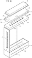
- Fig. 1 and Fig. 2 are perspective views of the non-burning type flavor inhaler 1 according to the first embodiment.
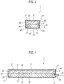
- Fig. 3 is a cross-sectional view along a lateral direction of the non-burning type flavor inhaler 1 according to the first embodiment.
- Fig. 4 is a cross-sectional view along a longitudinal direction of the non-burning type flavor inhaler 1 according to the first embodiment.
- the non-burning type flavor inhaler 1 includes a flavor generating source 2, a heat source 3, a holder 4, a lid 5, and a mouthpiece 6.
- the flavor generating source 2 and the heat source 3 are laminated inside the holder 4, and are contained inside the holder 4.
- the non-burning type flavor inhaler 1 has an approximately rectangular parallelepiped shape including a longitudinal direction L, a lateral direction S, and a thickness direction T.
- the longitudinal direction L for example, is a direction in which the air passing through the flavor generating source 2 flows.
- the lateral direction S is a direction approximately orthogonal to the longitudinal direction L and the thickness direction T.
- the thickness direction T is a direction in which the flavor generating source 2 and the heat source 3 are laminated.
- the size of the non-burning type flavor inhaler 1 in the lateral direction S is smaller than the size of the non-burning type flavor inhaler 1 in the longitudinal direction L. Furthermore, the size of the non-burning type flavor inhaler 1 in the thickness direction T is smaller than the size of the non-burning type flavor inhaler 1 in the lateral direction S.
- the flavor generating source 2 has the widest area and a plate shape (an approximately rectangular parallelepiped shape) including a pair of main surfaces 21 and 22 defined by the longitudinal direction L and the lateral direction S, a pair of side surfaces 23 and 24 defined by the lateral direction S and the thickness direction T, and a pair of side surfaces 25 and 26 defined by the longitudinal direction L and the thickness direction T.
- the pair of main surfaces 21 and 22 defined by the lateral direction S and the longitudinal direction L orthogonal to each other have a rectangular shape.
- the flavor generating source 2 may be realized by shredding a plant material such as tobacco leaves into an optional size and then filling the shredded leaves. Furthermore, the flavor generating source 2 may be realized by forming a plant material such as tobacco leaves in the shape of a sheet and then laminating the sheets, or the flavor generating source 2 may be a granular material wrapped in a pouch made of a nonwoven cloth having air permeability. Moreover, the flavor generating source 2 may be a compact manufactured by a method such as tablet making, extrusion, injection molding, and the like. In addition, as the plant material such as tobacco leaves, a plant material on which a process well-known in the art, such as heating and drying, is performed, if necessary, may be used.
- the flavor generating source 2 is a compact having air permeability.
- the flavor generating source 2 has air permeability that enables air to flow through the inside of the flavor generating source 2 along the longitudinal direction L.
- the flavor generating source 2 is realized by sandwiching a mixture of a granular tobacco body and a binding agent such as a thermoplastic resin between nonwoven cloths, whereby the flavor generating source 2 is formed in a sheet shape through thermal fusion bonding.
- the side surface 23 of the flavor generating source 2 has an inlet portion 9 for leading in air.
- the inlet portion 9 is a portion exposed to an inlet opening 7 of the holder 4 described later.
- the side surface 24 of the flavor generating source 2 has an outlet portion 10 for leading out air.
- the outlet portion 10 is a portion exposed to a mouthpiece 6 described later.
- the inlet portion 9 and the outlet portion 10 will be described in detail later.
- the flavor generating source 2 has air permeability. That is, the main surfaces 21 and 22, the pair of side surfaces 23 and 24, and the pair of side surfaces 25 and 26 of the flavor generating source 2 have air permeability.
- the air led in from the inlet portion 9 of the flavor generating source 2 passes through the inside of the flavor generating source 2, and is led out from the outlet portion 10.
- a flavor is added to the air led in from the inlet portion 9 while the flavor passes through the flavor generating source 2.
- a flavor capable of relaxing a user is preferably included as the flavor added to the air.
- the tobacco flavor is known as a flavor capable of relaxing a user.
- the flavor generating source preferably has a tobacco powder for adding the tobacco flavor.
- the grain size of the tobacco powder is preferably from 0.1 mm to 2.0 mm.
- the filler content of the tobacco powder is preferably from 100 mg to 1000 mg.
- the flavor generating source 2 may include a flavor stabilizer, such as menthol essence, propylene glycol, or a medium chain triglyceride (MCT), and various types of essences and flavor compounds that are well-known in the art may also be added.
- the flavor generating source 2 having tobacco powder is formed as a sheet-shaped compact having air permeability
- a binder such as a thermoplastic resin
- the binder of the thermoplastic resin in a range of 10 to 70 wt% (weight percent), and preferably in the range of 20 to 50 wt% with respect to the tobacco powder.
- thermoplastic resin e.g., polyethylene and polyamide, etc.
- EVA ethylene vinylalcohol copolymer
- the heat source 3 is formed in a plate shape configured by a pair of main surfaces 31 and 32 having the widest area, a pair of side surfaces 33 and 34 along the lateral direction, and a pair of side surfaces 35 and 36 along the longitudinal direction L.
- the heat source 3 In order to heat the flavor generating source 2, the heat source 3 generates a heat of 60°C or more. Particularly, it is preferable that the heat source 3 generates a heat of 90°C or more. It is possible to adopt electric heat and various types of heat of chemical reactions as the mode of generation of heat by the heat source 3. Chemical reactions that make use of the oxidation reaction heat using the oxygen in the atmosphere, as well as the latent heat are well-known as the chemical reactions accompanying the generation of heat. In the first embodiment, it is preferable to use the oxidation reaction heat of iron powder as the oxidation reaction heat. More particularly, the heat source 3 is configured by iron powder and an outer bag that stores the iron powder. The outer bag, for example, is configured by a nonwoven cloth having apertures that are smaller than the grain size of the iron powder.
- the heat source 3 it is preferable to secure air permeability of the heat source 3 in a state when the heat source 3 is stored in the holder 4.
- the lid 5 since the lid 5 has an opening 8, the air is supplied from the opening 8 to the main surface 31 of the heat source 3.
- the main surface 32 of the heat source 3 facing the flavor generating source 2 is preferably configured by a member that does not have air permeability.
- a member that does not have air permeability may be pasted on the main surface 32 of the heat source 3.
- the heat source 3 preferably includes iron powder, activated carbon, water, and sodium chloride as the heating element. If the total of the iron powder, activated carbon, water, and sodium chloride in the heating element is assumed to be 100 wt% (weight percent), the iron powder is preferably selected in the range of 30 to 60 wt% (weight percent). Similarly, the activated carbon is preferably selected in the range of 10 to 50 wt% (weight percent). Similarly, water is preferably selected in the range of 10 to 30 wt% (weight percent). Moreover, sodium chloride is preferably selected in the range of 0.5 to 7 wt% (weight percent).
- the weight percent of the iron powder, activated carbon, water, and sodium chloride is preferably 46:30:20:4 with the total of the iron powder, activated carbon, water, and sodium chloride being 100 wt% (weight percent).
- the total weight of the iron powder, activated carbon, water, and sodium chloride in the heat source 3 is preferably from 0.5 to 1.5 g.
- the temperature of the heat generated from the heat source 3 is preferably 90°C or more. If the temperature of the heat generated from the heat source 3 is 90°C or more, the flavor generating source 2 is heated sufficiently, and as a result, it is possible for a user to inhale sufficient flavor from the tobacco powder.
- the holder 4 has a box shape for storing the flavor generating source 2 and the heat source 3.
- the holder 4 has a plate-shaped bottom panel 42, a pair of plate-shaped wall panels 43 and 44 that rise up from near the lateral direction S of the bottom panel 42, and a pair of plate-shaped wall panels 45 and 46 that rise up from near the longitudinal direction L of the bottom panel 42.
- the wall panel 43 of the holder 4 has an inlet opening 7 for leading in air.
- the inlet opening 7 is an opening having a line shape.
- the inlet opening 7 may be configured by a plurality of dot-shaped openings.
- a mouthpiece 6 is provided on the wall panel 44 of the holder 4 for the user to inhale the flavor.
- the lid 5 is formed on the opposite side of the bottom panel 42 of the holder 4.
- the lid 5 functions as a lid of the holder 4 and has an opening 8.
- the opening 8 is formed to enable securing sufficient contact area between the heat source 3 and the air.
- the mouthpiece 6 leads to the inner side of the holder 4, and has a cylindrical shape.
- the mouthpiece 6 is formed in the center of the wall panel 44 in the lateral direction S.
- the holder 4 has a holding structure for holding the flavor generating source 2 and the heat source 3.
- the flavor generating source 2 and the heat source 3 are laminated inside the holder 4 so that the main surface 32 of the heat source 3 and the main surface 21 of the flavor generating source 2 are facing each other.
- the main surface 31 of the heat source 3 and the lid 5 lie in proximity, and are stored in the holder 4 so that the air is supplied from the main surface 31 of the heat source 3 via the opening 8 of the lid 5.
- the flavor generating source is stored in the holder 4 so that the main surface 22 of the flavor generating source 2 and the bottom panel 42 of the holder 4 are in contact.
- the thickness obtained by laminating the flavor generating source 2 and the heat source 3, in the thickness direction T is almost same as the thickness of the holder 4.
- the side surface 25 of the flavor generating source 2 and the side surface 35 of the heat source 3, as well as the wall panel 45 of the holder 4 lie in proximity.
- the side surface 26 of the flavor generating source 2 and the side surface 36 of the heat source 3, as well as the wall panel 46 of the holder 4 lie in proximity. That is, the width of the flavor generating source 2 and the heat source 3 in the lateral direction S, and the width of the holder 4 are almost the same.
- the flavor generating source 2 is stored in the holder 4 so that the side surface 23 of the flavor generating source 2 and the inlet opening 7 are facing each other, and the side surface 24 of the flavor generating source 2 and the mouthpiece 6 are facing each other. Furthermore, the side surface 23 of the flavor generating source 2 and the side surface 33 of the heat source 3, as well as the wall panel 43 of the holder 4 lie in proximity. The side surface 24 of the flavor generating source 2 and the side surface 34 of the heat source 3, as well as the wall panel 44 of the holder 4 lie in proximity. That is, the length of the flavor generating source 2 and the heat source 3 in the longitudinal direction L, and the length of the holder 4 are almost the same.
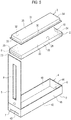
- Fig. 5 is a perspective view of the non-burning type flavor inhaler 1 having the open lid 5 according to the first embodiment.
- the inlet portion 9 is the portion where the air flowing in from the inlet opening 7 of the holder 4 is led in to the flavor generating source 2, and this area faces the inlet opening 7 of the holder 4.
- the outlet portion 10 is the portion where the air that has passed through the inside of the flavor generating source 2 is led out, and in the first embodiment, the outlet portion 10 faces the mouthpiece 6 of the holder 4, as shown in Fig. 5 . That is, the inlet portion 9 and the outlet portion 10 are provided on the surfaces other than the main surfaces 21 and 22 facing the heat source 3, among the surfaces provided in the flavor generating source 2.
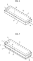
- Fig. 6 is a drawing showing a flow path of air in the flavor generating source 2 and the heat source 3, in a case when the flavor generating source 2 and the heat source 3 are inserted in the holder 4 of the non-burning type flavor inhaler 1 according to the first embodiment.
- the flavor generating source 2 and the heat source 3 are laminated and stored inside the holder 4 so that one main surface 32 of the heat source 3 and one main surface 21 of the flavor generating source 2 are facing each other, and the entire surface of the main surface 21 of the flavor generating source 2 is heated via the entire surface of the main surface 32 of the heat source 3.
- the air led in from the inlet portion 9 of the flavor generating source 2 via the inlet opening 7 of the holder 4 passes through the inside of the flavor generating source 2, and is led out from the outlet portion 10 of the flavor generating source 2 without changing the direction.
- the air led in from the inlet portion 9 of the flavor generating source 2 is led out from the outlet portion 10 of the flavor generating source 2 without passing through the inside of the heat source 3. That is, the holder 4 has a flow path through which the air led out from the outlet portion 10 is led to the mouthpiece 6. Specifically, the flow path is formed along the longitudinal direction L in the pair of main surfaces 21 and 22 provided in the flavor generating source 2 so that the air pass through the inside of the flavor generating source 2.
- the air led in from the inlet portion 9 of the flavor generating source 2 via the inlet opening 7 of the holder 4 passes through the outlet portion 10 of the flavor generating source 2, and is led out straight from the mouthpiece 6.
- the flavor generating source 2 and the heat source 3 are in the shape of a plate, as compared to a case in which the flavor generating source 2 and the heat source 3 are processed in a columnar shape or a cylindrical shape, it is possible to easily process the flavor generating source 2 and the heat source 3. If the flavor generating source 2 or the heat source 3 has a shape of granular manner, then as compared to a case in which the flavor generating source 2 and the heat source 3 are processed in a cylindrical shape, particularly, it is possible to easily process the flavor generating source 2 and the heat source 3.
- the non-burning type flavor inhaler 1 of the first embodiment since the entire surface of the main surface 21 of the flavor generating source 2 is heated via the entire surface of the main surface 32 of the heat source 3, it is possible to sufficiently heat the flavor generating source 2. It is possible to sufficiently heat the flavor generating source 2, and thus, upon inhalation by the user, it is possible to add a sufficient flavor to the air passing through the flavor generating source 2.
- the air passes across the entire inside of the flavor generating source 2, because of which it is possible to add a sufficient flavor to the air passing through the flavor generating source 2.
- the non-burning type flavor inhaler 1 of the first embodiment since the air led in from the inlet portion 9 of the flavor generating source 2 passes only through the inside of the flavor generating source 2 without passing through the inside of the heat source 3, upon inhalation by the user, it is possible to control the rise in the air-flow resistance.
- the size of the non-burning type flavor inhaler 1 in the thickness direction T is smaller than the size of the non-burning type flavor inhaler 1 in the lateral direction S. Therefore, as compared to a case in which the non-burning type flavor inhaler has a columnar shape, it is possible to reduce the non-burning type flavor inhaler 1 in size even if the volume of the non-burning type flavor inhaler is the same.
- the heat source is laminated on one of the pair of main surfaces of the flavor generating source 2.
- the heat sources are laminated on both of the pair of main surfaces of the flavor generating source 2.
- Fig. 7 is a drawing showing a flow path of air in the flavor generating source 2 and the heat source 3, in a case when the flavor generating source 2 and two heat sources 3 are inserted in the holder 4 of the non-burning type flavor inhaler 1 according to the first modification.
- the flavor generating source 2 and the heat source 3 are laminated inside the holder 4 so that one main surface 32 of the heat source 3 and one main surface 21 of the flavor generating source 2 are facing each other, and one main surface 32 of the other heat source 3 and the other main surface 22 of the flavor generating source 2 are facing each other. Therefore, the entire surface of the main surfaces 21 and 22 of the flavor generating source 2 is heated via the entire surface of the main surface 32 of the heat sources 3.
- the air led in from the inlet portion 9 of the flavor generating source 2 via the inlet opening 7 of the holder 4 passes through the inside of the flavor generating source 2, and then passes through the outlet portion 10 of the flavor generating source 2 before being led out from the mouthpiece 6 without changing the direction. Since a member that does not have air permeability is pasted on the main surface 32 of the heat source 3 and the main surface 32 of the other heat source 3, the air led in from the inlet portion 9 of the flavor generating source 2 is led out from the outlet portion 10 of the flavor generating source 2 without passing through the inside of the heat source 3 and the other heat source 3. That is, the holder 4 that stores the flavor generating source 2 and the heat sources has a flow path in the longitudinal direction L through which air flows.
- both of the pair of main surfaces 21 and 22 of the flavor generating source 2 are heated via the main surface 32 of the two heat sources 3, it is possible to sufficiently heat the flavor generating source 2. It is possible to sufficiently heat the flavor generating source 2, and thus, upon inhalation by the user, it is possible to add a sufficient flavor to the air passing through the flavor generating source 2.
- the inlet opening is formed in a wall panel rising up from near the lateral direction of the bottom panel of the holder, the inlet portion of air into the flavor generating source is provided on the side surface of the flavor generating source facing the inlet opening.
- Fig. 8 and Fig. 9 are perspective views of the non-burning type flavor inhaler 1 according to the second embodiment.
- the inlet opening 7A is an opening that leads in air, and is formed on both the wall panels 45 and 46 of the holder 4.
- the inlet opening 7A is formed so that the area of the inlet opening 7A reduces gradually from the wall panel 43 along the lateral direction toward the wall panel 44 along the lateral direction. That is, the inlet opening 7A is formed so that the area of the inlet opening 7A reduces gradually from the wall panel 43 that does not have the mouthpiece 6 toward the wall panel 44 that has the mouthpiece 6. That is, the inlet opening 7A, for example, is preferably formed in the shape of an isosceles triangle.
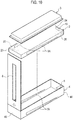
- Fig. 10 is a perspective view of the non-burning type flavor inhaler 1 having the open lid 5 according to the second embodiment.
- the inlet portion 9A is the portion where the air flowing in from the inlet opening 7A of the holder 4 is led in to the flavor generating source 2, and this area faces the inlet opening 7A provided on both side walls of the holder 4.
- the outlet portion 10 is the portion where the air that has passed through the inside of the flavor generating source 2 is led out, and in the second embodiment, the outlet portion 10 faces the mouthpiece 6 of the holder 4, as shown in Fig. 10 . That is, the inlet portion 9A and the outlet portion 10 are provided on the surfaces other than the main surfaces 21 and 22 facing the heat source 3, among the surfaces provided in the flavor generating source 2.
- the inlet portion 9A of the flavor generating source 2 faces each inlet opening 7A of the holder 4.
- the inlet opening 7A of the holder 4 is formed so that the area of the inlet opening 7A reduces gradually from the wall panel 43 that does not have the mouthpiece 6 toward the wall panel 44 that has the mouthpiece 6.
- Fig. 11 is a drawing showing a flow path of air in the flavor generating source 2 and the heat source 3, in a case when the flavor generating source 2 and the heat source 3 are inserted in the holder 4 of the non-burning type flavor inhaler 1.
- the air led in from both the inlet portions 9A of the flavor generating source 2 via both the inlet opening 7A of the holder 4 passes through the outlet portion 10 of the flavor generating source 2 after changing the direction inside the flavor generating source 2, and is then led out from the mouthpiece 6.
- the area of the inlet opening 7A keeps widening further away from the mouthpiece 6, approximately the same amount of air is led into the flavor generating source 2 in the inlet portion 9A close to the side surface 23 and the inlet portion 9A close to the side surface 24.
- the air led in from the inlet portion 9A of the flavor generating source 2 is led out from the outlet portion 10 of the flavor generating source 2 without passing through the inside of the heat source 3. That is, the air led in to the inlet portion 9A parallel to the lateral direction S is led out from the outlet portion 10 after changing the direction in the flavor generating source 2 so as to be parallel to the longitudinal direction L. That is, the holder 4 that stores the flavor generating source 2 and the heat source 3 according to the second embodiment has a flow path in which the air led in along the lateral direction S is led out from the mouthpiece after changing the direction so as to become parallel to the longitudinal direction L.
- the non-burning type flavor inhaler 1 of the second embodiment since the air is led in from the inlet portion 9A provided in the pair of side surfaces 25 and 26, and the air passes across the entire inside of the flavor generating source 2, upon inhalation by the user, it is possible to add a sufficient flavor to the air passing through the flavor generating source 2.
- the non-burning type flavor inhaler 1 of the second embodiment as compared to the case when the inlet portion 9 is provided only in the side surface 23, it is possible to shorten the length of the flow path inside the flavor generating source 2. Accordingly, it is possible to control a rise in the air-flow resistance.
- the heat source is laminated on one of the main surfaces of the flavor generating source.
- the heat source is laminated on both of the pair of main surfaces of the flavor generating source.
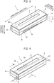
- Fig. 12 is a drawing showing a flow path of air in the flavor generating source 2 and the heat source 3, in a case when the flavor generating source 2 and two heat sources 3 are inserted in the holder 4 of the non-burning type flavor inhaler 1.
- the flavor generating source 2 and the heat source 3 are laminated inside the holder 4 so that one main surface 32 of the heat source 3 and one main surface 21 of the flavor generating source 2 are facing each other, and the main surface 32 of the other heat source 3 and the other main surface 22 of the flavor generating source 2 are facing each other. Therefore, the entire surface of the both main surfaces 21 and 22 of the flavor generating source 2 are heated via the entire surface of the main surface 32 of the two heat sources 3.
- both the main surfaces 21 and 22 of the flavor generating source 2 are heated via the main surface 32 of the two heat sources 3, it is possible to sufficiently heat the flavor generating source 2. It is possible to sufficiently heat the flavor generating source 2, and thus, upon inhalation by the user, it is possible to add a sufficient flavor to the air passing through the flavor generating source 2.
- the inlet openings are formed in both the wall panels rising up from near the longitudinal direction of the bottom panel of the holder, the inlet portions of air into the flavor generating source are provided on both the side surfaces of the flavor generating source facing the inlet opening. Moreover, in the second embodiment, the width of the flavor generating source and the heat source in the lateral direction, and the width of the holder are almost the same.
- the inlet opening is formed in one of the wall panels rising up from near the longitudinal direction of the bottom panel of the holder, the inlet portion of air into the flavor generating source is provided on one of the side surfaces of the flavor generating source that are facing the inlet opening.
- the width of the flavor generating source and the heat source in the lateral direction is lesser than the width of the holder, a space is formed inside the holder.
- the mouthpiece is formed to lead to the space of the holder.
- Fig. 13 and Fig. 14 are perspective views of the non-burning type flavor inhaler 1 according to the third embodiment.
- Fig. 15 is a cross-sectional view along the lateral direction of the non-burning type flavor inhaler 1 according to the third embodiment.
- Fig. 16 is a cross-sectional view along the longitudinal direction L of the non-burning type flavor inhaler 1 according to the third embodiment.
- the inlet opening 7A is an opening that leads in air, and is formed only on the wall panel 46 of the holder 4.
- the inlet opening 7A is not formed in the wall panel 45 of the holder 4.
- the mouthpiece 6 is formed in the wall panel 44 along the lateral direction S, in the proximity of the wall panel 45.
- the side surface 25 of the flavor generating source 2 and the side surface 35 of the heat source 3, as well as the wall panel 45 of the holder 4 do not lie in proximity.
- a space X is formed between the side surface 25 of the flavor generating source 2 and the side surface 35 of the heat source 3, as well as the wall panel 45 of the holder 4. That is, the width of the flavor generating source and the heat source in the lateral direction S is lesser than the width of the holder.
- the mouthpiece 6 is formed to lead to the space X of the holder 4.
- the side surface 23 of the flavor generating source 2 and the side surface 33 of the heat source 3, as well as the wall panel 43 of the holder 4 lie in proximity.
- the side surface 24 of the flavor generating source 2 and the side surface 34 of the heat source 3, as well as the wall panel 44 of the holder 4 lie in proximity. That is, the length of the flavor generating source 2 and the heat source 3 in the longitudinal direction L, and the length of the holder 4 are almost the same.
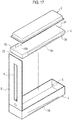
- Fig. 17 is a perspective view of the non-burning type flavor inhaler 1 having the open lid 5 according to the third embodiment.
- the inlet portion 9A is the portion where the air flowing in from the inlet opening 7A of the holder 4 is led in to the flavor generating source 2, and this area faces the inlet opening 7A provided only on the wall panel 46 of the holder 4.
- the outlet portion 10A is the portion where the air that has passed through the inside of the flavor generating source 2 is led out, and the outlet portion 10A faces the wall panel 45 of the holder 4. That is, the inlet portion 9A and the outlet portion 10A are provided on the surfaces other than the main surface facing the heat source 3, among the surfaces provided in the flavor generating source 2.
- the inlet portion 9A of the flavor generating source 2 faces the inlet opening 7A of the holder 4.
- the inlet opening 7A of the holder 4 is formed so as to narrow down gradually from the wall panel 43 that does not have the mouthpiece 6 toward the wall panel 44 that has the mouthpiece 6. Therefore, approximately the same amount of air is led out throughout the longitudinal direction L in the outlet portion 10A of the flavor generating source 2 as well.
- Fig. 18 is a drawing showing a flow path of air in the flavor generating source 2 and the heat source 3, in a case when the flavor generating source 2 and the heat source 3 are inserted in the holder 4 of the non-burning type flavor inhaler 1.
- the air led in from only the inlet portion 9A of the flavor generating source 2 via the inlet opening 7A of the holder 4 passes through the outlet portion 10A of the flavor generating source 2, and is then led out from the mouthpiece 6.
- the area of the inlet opening 7A keeps widening further away from the mouthpiece 6, approximately the same amount of air is led into the flavor generating source 2 in the inlet portion 9A close to the side surface 24 and the inlet portion 9A close to the side surface 23.
- the air led in from the inlet portion 9A of the flavor generating source 2 is led out from the outlet portion 10A of the flavor generating source 2 without passing through the inside of the heat source 3. That is, the air led in to the inlet portion 9A parallel to the lateral direction and led out from the outlet portion 10A is led out from the mouthpiece 6 after changing the direction in the space X of the holder 4 so as to become parallel to the longitudinal direction L.
- the holder 4 that stores the flavor generating source 2 and the heat source 3 has a flow path in which the air led in along the lateral direction S is led out from the mouthpiece 6 after changing the direction in the space X so as to become parallel to the longitudinal direction L.
- the air that passes through inside the flavor generating source 2 passes through approximately parallel to the lateral direction S, it is possible to shorten the length of the flow path, and possible to control the rise in the air-flow resistance.
- the heat source is laminated on one of the main surfaces of the flavor generating source.
- the heat source is laminated on both of the pair of main surfaces of the flavor generating source.
- Fig. 19 is a drawing showing a flow path of air in a case when the flavor generating source 2 and two heat sources 3 are inserted in the non-burning type flavor inhaler 1.
- the flavor generating source 2 and the heat source 3 are laminated inside the holder 4 so that one main surface 32 of the heat source 3 and one main surface 21 of the flavor generating source 2 are facing each other, and the main surface 32 of the other heat source 3 and the other main surface 22 of the flavor generating source 2 are facing each other. Therefore, the entire surface of the both main surfaces 21 and 22 of the flavor generating source 2 are heated via the entire surface of the main surface 32 of the two heat sources 3.
- both the main surfaces 21 and 22 of the flavor generating source 2 are heated via the main surface 32 of the two heat sources 3, it is possible to sufficiently heat the flavor generating source 2. It is possible to sufficiently heat the flavor generating source 2, and thus, upon inhalation by the user, it is possible to add a sufficient flavor to the air passing through the flavor generating source 2.
- the inlet opening is formed so that the area of the inlet opening reduces gradually from the wall panel that does not have the mouthpiece toward the wall panel that has the mouthpiece.
- the inlet opening formed in both the wall panels rising from near the longitudinal direction of the bottom panel of the holder is approximately the same shape across the longitudinal direction.
- the non-burning type flavor inhaler has a holder that stores a flavor generating source and a heat source.
- the non-burning type flavor inhaler has a holder that stores a flavor generating source, a heat source, and a rectification member.
- Fig. 20 and Fig. 21 are perspective views of the non-burning type flavor inhaler 1 according to the fourth embodiment.
- Fig. 22 is a cross-sectional view along a lateral direction of the non-burning type flavor inhaler 1 according to the fourth embodiment.
- Fig. 23 is a cross-sectional view along the longitudinal direction L of the non-burning type flavor inhaler 1 according to the fourth embodiment.
- the non-burning type flavor inhaler 1 includes a flavor generating source 2, a heat source 3, a holder 4, a lid 5, a mouthpiece 6, and a rectification member 11.
- the inlet opening 7B is an opening that leads in air, and is formed on both the wall panels 45 and 46 of the holder 4.
- the inlet opening 7B may be line-shaped.
- the inlet opening 7B may be dot-shaped.
- a dot shape is a shape in which a plurality of small openings are collected together.
- both the side surfaces 25 and 26 of the flavor generating source 2 have an inlet portion 9B.
- the main surface 22 of the flavor generating source 2 has an outlet portion 10B.
- the inlet portion 9B and the outlet portion 10B will be described in detail later.
- the mouthpiece 6 leads to the inner side of the holder 4, and has a cylindrical shape.
- the mouthpiece 6 is formed in a circular shape in the center of the wall panel 44 of the holder 4.
- the center of the wall panel 44 of the holder 4 is provided at a position whose distance from the pair of wall panels 45 and 46 along the longitudinal direction L is approximately equal.
- the rectification member 11 has the widest area and a plate shape (an approximately rectangular parallelepiped shape) including a pair of main surfaces 111 and 112 defined by the longitudinal direction L and the lateral direction S, a pair of side surfaces 113 and 114 defined by the lateral direction S and the thickness direction T, and a pair of side surfaces 115 and 116 defined by the longitudinal direction L and the thickness direction T.
- a rectification member opening 12 is formed so as to penetrate the pair of main surfaces 111 and 112 provided in the rectification member 11.
- the flavor generating source 2 and the heat source 3 are laminated inside the holder 4 so that the main surface 32 of the heat source 3 and the main surface 21 of the flavor generating source 2 are facing each other.
- the flavor generating source 2 and the rectification member 11 are laminated inside the holder 4 so that the main surface 22 of the flavor generating source 2 and the main surface 111 of the rectification member are facing each other.
- the main surface 31 of the heat source 3 and the lid 5 lie in proximity, and are stored in the holder 4 so that the air is supplied from the main surface 31 of the heat source 3 via the opening 8 of the lid 5.
- the rectification member 11 is installed on a convex portion W protruding in the inner side along the lateral direction S along the longitudinal direction L.
- the rectification member 11 is stored inside the holder 4 so that a space Y is formed between the main surface 112 of the rectification member 11 and the bottom panel 42 of the holder 4. That is, the thickness obtained by laminating the flavor generating source 2, the heat source 3, and the rectification member 11, in the thickness direction T, is lesser than the thickness of the holder 4.
- the side surface 25 of the flavor generating source 2, the side surface 35 of the heat source 3, and the side surface 115 of the rectification member 11, as well as the wall panel 45 of the holder 4 lie in proximity.
- the side surface 26 of the flavor generating source 2, the side surface 36 of the heat source 3, and the side surface 116 of the rectification member 11, as well as the wall panel 46 of the holder 4 lie in proximity. That is, the width of the flavor generating source 2, the heat source 3, and the rectification member 11 in the lateral direction S, and the width of the holder 4 are almost the same.
- the side surface 23 of the flavor generating source 2, the side surface 33 of the heat source 3, and the side surface 113 of the rectification member 11, as well as the wall panel 43 of the holder 4 lie in proximity.
- the side surface 24 of the flavor generating source 2, the side surface 34 of the heat source 3, and the side surface 114 of the rectification member 11, as well as the wall panel 44 of the holder 4 lie in proximity. That is, the length of the flavor generating source 2, the heat source 3, and the rectification member 11 in the longitudinal direction L, and the length of the holder 4 are almost the same.
- the flavor generating source 2, the heat source 3, and the rectification member 11 are stored in the holder 4 so that the space Y and the mouthpiece 6 are facing each other.
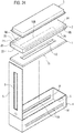
- Fig. 24 is a perspective view of the non-burning type flavor inhaler 1 having the open lid 5 according to the fourth embodiment.
- the inlet portion 9B is the portion where the air flowing in from the inlet opening 7B is led in to the inside of the flavor generating source 2, and this area faces each inlet opening 7B provided on the wall panels of the holder 4.
- the outlet portion 10B is the portion where the air that has passed through the inside of the flavor generating source 2 is led out, and the outlet portion 10B faces the space Y via the rectification member 11. That is, the inlet portion 9B is provided on the surface other than the main surface facing the heat source 3, among the surfaces provided in the flavor generating source 2.
- Fig. 25 is a drawing showing a flow path of air in a case when the flavor generating source 2 and the heat source 3 is inserted in the non-burning type flavor inhaler 1.
- the air led in from the inlet portion 9B of the flavor generating source 2 via the inlet opening 7B of the holder 4 passes through the outlet portion 10B of the flavor generating source 2 and the rectification member opening 12 of the rectification member 11, and is then led out from the mouthpiece 6. Since the main surface 32 of the heat source 3 that is facing the flavor generating source 2 does not have air permeability, the air led in from the inlet portion 9B of the flavor generating source 2 is led out from the outlet portion 10B of the flavor generating source 2 without passing through the inside of the heat source 3.
- the air led in to the inlet portion 9B parallel to the lateral direction S and led out from the outlet portion 10B is led out from the mouthpiece 6 after changing the direction in the flavor generating source 2 so as to become perpendicular to the lateral direction S and the longitudinal direction L, and then again changing the direction in the space Y of the holder 4 so as to become parallel to the longitudinal direction L.
- the holder 4 that stores the flavor generating source 2 and the heat source 3 has a flow path where the air led in to the inlet portion 9B parallel to the lateral direction S and led out from the outlet portion 10B is led out from the mouthpiece after changing the direction in the flavor generating source 2 so as to become perpendicular to the lateral direction S and the longitudinal direction L, then passing through the rectification member opening 12, and then again changing the direction in the space Y of the holder 4 so as to become parallel to the longitudinal direction L.
- the rectification member 11 leads the air into the space Y of the holder 4.
- the flow of the air led in to the inlet portion 9B parallel to the lateral direction S and led out from the outlet portion 10B is controlled by the rectification member 11 so that the air flows through the entire inside of the flavor generating source 2, and as a result, upon being inhaled by the user, it is possible to control the air-flow resistance while adding sufficient flavor to the air passing through the flavor generating source 2.
- the thickness obtained by laminating the flavor generating source, the heat source, and the rectification member, in the thickness direction T is lesser than the thickness of the holder. Furthermore, in the fourth embodiment, the mouthpiece is formed in one of the wall panels rising up from near the lateral direction of the bottom panel of the holder.
- the thickness obtained by laminating the flavor generating source, the heat source, and the rectification member, in the thickness direction, is almost same as the thickness of the holder.
- the mouthpiece is formed in the bottom panel of the holder.
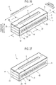
- Fig. 26 and Fig. 27 are perspective views of the non-burning type flavor inhaler 1 according to the fifth embodiment.
- Fig. 28 is a cross-sectional view along the lateral direction of the non-burning type flavor inhaler 1 according to the fifth embodiment.
- Fig. 29 is a cross-sectional view along the longitudinal direction L of the non-burning type flavor inhaler 1 according to the fifth embodiment.
- both the side surfaces 25 and 26 of the flavor generating source 2 have an inlet portion 9B.
- the main surface 22 of the flavor generating source 2 has an outlet portion 10B.
- the inlet portion 9B and the outlet portion 10B will be described in detail later.
- the mouthpiece 6 leads to the inner side of the holder 4, and has a cylindrical shape.
- the mouthpiece 6 is formed in a circular shape in the center of the bottom panel 42 of the holder 4.
- the center of the bottom panel 42 of the holder 4 is provided at a position whose distance from the pair of wall panels 45 and 46 along the longitudinal direction L, and the pair of wall panels 43 and 44 along the lateral direction S is approximately equal.
- the flavor generating source 2 and the heat source 3 are laminated inside the holder 4 so that the main surface 32 of the heat source 3 and the main surface 21 of the flavor generating source 2 are facing each other.
- the flavor generating source 2 and the rectification member 11 are laminated inside the holder 4 so that the main surface 22 of the flavor generating source 2 and the main surface 111 of the rectification member 11 are facing each other.
- the main surface 31 of the heat source 3 and the lid 5 lie in proximity, and are stored in the holder 4 so that the air is supplied from the main surface 31 of the heat source 3 via the opening 8 of the lid 5.
- the rectification member 11 is stored inside the holder 4 so that the main surface 112 of the rectification member 11 and the bottom panel 42 of the holder 4 are in close contact. That is, the thickness obtained by laminating the flavor generating source 2, the heat source 3, and the rectification member 11, in the thickness direction T, is almost same as the thickness of the holder 4. Furthermore, the side surface 25 of the flavor generating source 2, the side surface 35 of the heat source 3, and the side surface 115 of the rectification member 11, as well as the wall panel 45 of the holder 4 lie in proximity. The side surface 26 of the flavor generating source 2, the side surface 36 of the heat source 3, and the side surface 116 of the rectification member 11, as well as the wall panel 46 of the holder 4 lie in proximity. That is, the width of the flavor generating source 2, the heat source 3, and the rectification member 11 in the lateral direction S, and the width of the holder 4 are almost the same.
- the side surface 23 of the flavor generating source 2, the side surface 33 of the heat source 3, and the side surface 113 of the rectification member 11, as well as the wall panel 43 of the holder 4 lie in proximity.
- the side surface 24 of the flavor generating source 2, the side surface 34 of the heat source 3, and the side surface 114 of the rectification member 11, as well as the wall panel 44 of the holder 4 lie in proximity. That is, the length of the flavor generating source 2, the heat source 3, and the rectification member 11 in the longitudinal direction L, and the length of the holder 4 are almost the same.
- the rectification member 11 is stored in the holder 4 so that the rectification member opening 12 of the rectification member 11 faces the mouthpiece 6.
- Fig. 30 is a perspective view of the non-burning type flavor inhaler 1 having the open lid 5 according to the fifth embodiment.
- the inlet portion 9B is the portion where the air flowing in from the inlet opening 7B is led in to the inside of the flavor generating source 2, and this area faces each inlet opening 7B provided on both the wall panels 45 and 46 of the holder 4.
- the outlet portion 10B is the portion where the air that has passed through the inside of the flavor generating source 2 is led out, and the outlet portion 10B faces the mouthpiece 6. That is, the inlet portion 9B is provided on the surface other than the main surface facing the heat source 3, among the surfaces provided in the flavor generating source 2.
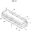
- Fig. 31 is a drawing showing a flow path of air in the flavor generating source 2 and the heat source 3, in a case when the flavor generating source 2, the heat source 3, and the rectification member 11 are inserted in the holder 4 of the non-burning type flavor inhaler 1.
- the air led in from both the inlet portions 9B of the flavor generating source 2 via the inlet opening 7B of the holder 4 is led out from the outlet portion 10B of the flavor generating source 2. Since the main surface 32 of the heat source 3 that is facing the flavor generating source 2 does not have air permeability, the air led in from the inlet portion 9B of the flavor generating source 2 is led out from the outlet portion 10B of the flavor generating source 2 without passing through the inside of the heat source 3.
- the air led in to the inlet portion 9B parallel to the lateral direction S and led out from the outlet portion 10b is led out from the mouthpiece 6 after changing the direction in the flavor generating source 2 so as to become perpendicular to the lateral direction S and the longitudinal direction L.
- the holder 4 that stores the flavor generating source 2 and the heat source 3 has a flow path where the air led in to the inlet portion 9B parallel to the lateral direction S and led out from the outlet portion 10B is led out from the mouthpiece 6 after changing the direction in the flavor generating source 2 so as to become perpendicular to the lateral direction S and the longitudinal direction L.
- the air led in to the inlet portion 9B parallel to the lateral direction S is led out from the outlet portion 10B after changing the direction in the flavor generating source 2 so as to become perpendicular to the lateral direction S and the longitudinal direction L, and as a result, upon being inhaled by the user, it is possible to control the air-flow resistance while adding sufficient flavor to the air passing through the flavor generating source 2.
Landscapes
- Health & Medical Sciences (AREA)
- Engineering & Computer Science (AREA)
- Anesthesiology (AREA)
- Biomedical Technology (AREA)
- Heart & Thoracic Surgery (AREA)
- Hematology (AREA)
- Life Sciences & Earth Sciences (AREA)
- Animal Behavior & Ethology (AREA)
- General Health & Medical Sciences (AREA)
- Public Health (AREA)
- Veterinary Medicine (AREA)
- Bioinformatics & Cheminformatics (AREA)
- Pulmonology (AREA)
- Thermotherapy And Cooling Therapy Devices (AREA)
- Manufacture Of Tobacco Products (AREA)
Priority Applications (1)
| Application Number | Priority Date | Filing Date | Title |
|---|---|---|---|
| PL13846670T PL2907397T3 (pl) | 2012-10-18 | 2013-10-04 | Inhalator aromatu typu niepalnego |
Applications Claiming Priority (2)
| Application Number | Priority Date | Filing Date | Title |
|---|---|---|---|
| JP2012231149 | 2012-10-18 | ||
| PCT/JP2013/077137 WO2014061477A1 (ja) | 2012-10-18 | 2013-10-04 | 非燃焼型香味吸引器 |
Publications (3)
| Publication Number | Publication Date |
|---|---|
| EP2907397A1 EP2907397A1 (en) | 2015-08-19 |
| EP2907397A4 EP2907397A4 (en) | 2016-06-22 |
| EP2907397B1 true EP2907397B1 (en) | 2017-09-06 |
Family
ID=50488046
Family Applications (1)
| Application Number | Title | Priority Date | Filing Date |
|---|---|---|---|
| EP13846670.1A Active EP2907397B1 (en) | 2012-10-18 | 2013-10-04 | Non-combustion-type flavor inhaler |
Country Status (6)
| Country | Link |
|---|---|
| US (1) | US10420372B2 (pl) |
| EP (1) | EP2907397B1 (pl) |
| JP (1) | JP5895062B2 (pl) |
| PL (1) | PL2907397T3 (pl) |
| TW (1) | TW201431505A (pl) |
| WO (1) | WO2014061477A1 (pl) |
Cited By (6)
| Publication number | Priority date | Publication date | Assignee | Title |
|---|---|---|---|---|
| US10918820B2 (en) | 2011-02-11 | 2021-02-16 | Batmark Limited | Inhaler component |
| US11083856B2 (en) | 2014-12-11 | 2021-08-10 | Nicoventures Trading Limited | Aerosol provision systems |
| US11253671B2 (en) | 2011-07-27 | 2022-02-22 | Nicoventures Trading Limited | Inhaler component |
| US11744964B2 (en) | 2016-04-27 | 2023-09-05 | Nicoventures Trading Limited | Electronic aerosol provision system and vaporizer therefor |
| US12274824B2 (en) | 2015-10-01 | 2025-04-15 | Nicoventures Trading Limited | Aerosol provision system |
| US12447290B2 (en) | 2008-10-23 | 2025-10-21 | Nicoventures Trading Limited | Inhaler |
Families Citing this family (68)
| Publication number | Priority date | Publication date | Assignee | Title |
|---|---|---|---|---|
| EP3834869B1 (en) | 2010-12-22 | 2024-06-05 | Syqe Medical Ltd. | System for drug delivery |
| PL2753202T3 (pl) | 2011-09-06 | 2016-11-30 | Podgrzewanie materiału przeznaczonego do palenia | |
| EP3892125A3 (en) | 2011-09-06 | 2022-01-05 | Nicoventures Trading Limited | Heating smokable material |
| AT511344B1 (de) | 2011-10-21 | 2012-11-15 | Helmut Dr Buchberger | Inhalatorkomponente |
| GB201207039D0 (en) | 2012-04-23 | 2012-06-06 | British American Tobacco Co | Heating smokeable material |
| GB2504076A (en) | 2012-07-16 | 2014-01-22 | Nicoventures Holdings Ltd | Electronic smoking device |
| GB2504075A (en) | 2012-07-16 | 2014-01-22 | Nicoventures Holdings Ltd | Electronic smoking device |
| GB201217067D0 (en) | 2012-09-25 | 2012-11-07 | British American Tobacco Co | Heating smokable material |
| GB2513639A (en) | 2013-05-02 | 2014-11-05 | Nicoventures Holdings Ltd | Electronic cigarette |
| GB201407426D0 (en) | 2014-04-28 | 2014-06-11 | Batmark Ltd | Aerosol forming component |
| CA3219298A1 (en) * | 2014-06-30 | 2016-01-07 | Syqe Medical Ltd. | Drug dose cartridge for an inhaler device |
| AU2015283589B2 (en) | 2014-06-30 | 2019-09-12 | Syqe Medical Ltd. | Method and device for vaporization and inhalation of isolated substances |
| US11298477B2 (en) | 2014-06-30 | 2022-04-12 | Syqe Medical Ltd. | Methods, devices and systems for pulmonary delivery of active agents |
| IL273507B2 (en) | 2014-06-30 | 2024-06-01 | Syqe Medical Ltd | Methods, devices and systems for administering active substances through the lungs |
| CN113616883B (zh) | 2014-06-30 | 2023-06-06 | Syqe医药有限公司 | 向受试者肺部递送植物材料中的至少一药理活性剂的系统 |
| RU2723335C2 (ru) * | 2014-06-30 | 2020-06-09 | Сике Медикал Лтд. | Дозовый картридж для ингалятора |
| RU2721064C2 (ru) | 2014-06-30 | 2020-05-15 | Сике Медикал Лтд. | Ингалятор с регулированием потока |
| CA2951396A1 (en) * | 2014-07-11 | 2016-01-14 | Philip Morris Products S.A. | Aerosol-generating system comprising a removable heater |
| US10058123B2 (en) | 2014-07-11 | 2018-08-28 | R. J. Reynolds Tobacco Company | Heater for an aerosol delivery device and methods of formation thereof |
| GB2528673B (en) | 2014-07-25 | 2020-07-01 | Nicoventures Holdings Ltd | Aerosol provision system |
| GB201505597D0 (en) | 2015-03-31 | 2015-05-13 | British American Tobacco Co | Article for use with apparatus for heating smokable material |
| GB201505595D0 (en) | 2015-03-31 | 2015-05-13 | British American Tobacco Co | Cartridge for use with apparatus for heating smokeable material |
| GB201505593D0 (en) | 2015-03-31 | 2015-05-13 | British American Tobacco Co | Article for use with apparatus for heating smokable material |
| RU2716195C2 (ru) * | 2015-04-15 | 2020-03-06 | Филип Моррис Продактс С.А. | Устройство для введения в ингалятор вкусового ароматизирующего вещества |
| GB201511361D0 (en) | 2015-06-29 | 2015-08-12 | Nicoventures Holdings Ltd | Electronic vapour provision system |
| GB201511349D0 (en) | 2015-06-29 | 2015-08-12 | Nicoventures Holdings Ltd | Electronic aerosol provision systems |
| WO2017011865A1 (en) | 2015-07-20 | 2017-01-26 | Medical Developments International Limited | Inhaler device for inhalable liquids |
| WO2017011867A1 (en) * | 2015-07-20 | 2017-01-26 | Medical Developments International Limited | Inhaler device for inhalable liquids |
| US11924930B2 (en) | 2015-08-31 | 2024-03-05 | Nicoventures Trading Limited | Article for use with apparatus for heating smokable material |
| US20170055575A1 (en) | 2015-08-31 | 2017-03-02 | British American Tobacco (Investments) Limited | Material for use with apparatus for heating smokable material |
| US20170055584A1 (en) | 2015-08-31 | 2017-03-02 | British American Tobacco (Investments) Limited | Article for use with apparatus for heating smokable material |
| US20170055574A1 (en) | 2015-08-31 | 2017-03-02 | British American Tobacco (Investments) Limited | Cartridge for use with apparatus for heating smokable material |
| US11641874B2 (en) | 2015-09-09 | 2023-05-09 | R.J. Reynolds Tobacco Company | Flavor delivery article |
| US20170119048A1 (en) * | 2015-10-30 | 2017-05-04 | British American Tobacco (Investments) Limited | Article for Use with Apparatus for Heating Smokable Material |
| US20180317554A1 (en) | 2015-10-30 | 2018-11-08 | British American Tobacco (Investments) Limited | Article for use with apparatus for heating smokable material |
| US20170119049A1 (en) | 2015-10-30 | 2017-05-04 | British American Tobacco (Investments) Limited | Article for Use with Apparatus for Heating Smokable Material |
| US20170119050A1 (en) * | 2015-10-30 | 2017-05-04 | British American Tobacco (Investments) Limited | Article for Use with Apparatus for Heating Smokable Material |
| US20170119051A1 (en) | 2015-10-30 | 2017-05-04 | British American Tobacco (Investments) Limited | Article for Use with Apparatus for Heating Smokable Material |
| US20170119046A1 (en) | 2015-10-30 | 2017-05-04 | British American Tobacco (Investments) Limited | Apparatus for Heating Smokable Material |
| US20170119047A1 (en) | 2015-10-30 | 2017-05-04 | British American Tobacco (Investments) Limited | Article for Use with Apparatus for Heating Smokable Material |
| GB201520056D0 (en) | 2015-11-13 | 2015-12-30 | British American Tobacco Co | Tobacco blend |
| CA3009599A1 (en) | 2016-01-06 | 2017-07-13 | Syqe Medical Ltd. | Low dose therapeutic treatment |
| CN120586220A (zh) * | 2016-01-11 | 2025-09-05 | Syqe医药有限公司 | 个人用蒸发装置 |
| US12478096B2 (en) | 2016-06-29 | 2025-11-25 | Nicoventures Trading Limited | Apparatus for heating smokable material |
| PL3478104T3 (pl) | 2016-06-29 | 2023-05-08 | Nicoventures Trading Limited | Urządzenie do ogrzewania materiału do palenia |
| KR102468749B1 (ko) | 2016-06-29 | 2022-11-17 | 니코벤처스 트레이딩 리미티드 | 흡연가능 물질을 가열하기 위한 장치 |
| UA125470C2 (uk) | 2016-11-10 | 2022-03-23 | Брітіш Амерікан Тобакко (Інвестментс) Лімітед | Тютюнова суміш |
| BR112019009137A2 (pt) | 2016-11-10 | 2019-07-16 | British American Tobacco Investments Ltd | composição, dispositivo, cartucho e método para gerar um meio inalável |
| EP3581037A4 (en) * | 2017-02-08 | 2020-12-16 | Japan Tobacco Inc. | CARTRIDGE AND INHALER |
| CA3050414C (en) | 2017-02-08 | 2022-06-21 | Japan Tobacco Inc. | Cartridge and inhaler |
| EP4201239A1 (en) | 2017-09-15 | 2023-06-28 | Nicoventures Trading Limited | Apparatus for heating smokable material |
| JP7408547B2 (ja) * | 2017-12-20 | 2024-01-05 | フィリップ・モーリス・プロダクツ・ソシエテ・アノニム | 油添加剤を含むエアロゾル発生基体 |
| WO2019162508A1 (en) * | 2018-02-26 | 2019-08-29 | Nerudia Limited | A substitute smoking consumable |
| WO2019162506A1 (en) * | 2018-02-26 | 2019-08-29 | Nerudia Limited | A substitute smoking consumable |
| EP3758517A1 (en) * | 2018-02-26 | 2021-01-06 | Nerudia Limited | A substitute smoking consumable |
| CN112638617B (zh) * | 2018-09-06 | 2023-03-21 | 日本烟草产业株式会社 | 挤出机的控制方法以及使用了该挤出机的控制方法的香味源的制造方法、和挤出机以及使用了该挤出机的挤出成型系统 |
| US11523470B2 (en) * | 2019-01-18 | 2022-12-06 | Altria Client Services Llc | Non-combustible aerosol system and pre-aerosol formulation housing |
| EP3782491A1 (en) * | 2019-08-23 | 2021-02-24 | Nerudia Limited | A substitute smoking consumable |
| PL4017291T3 (pl) * | 2019-08-23 | 2025-03-31 | Imperial Tobacco Limited | Materiał zużywalny zastępujący palenie |
| JP1653996S (pl) * | 2019-08-27 | 2021-03-01 | ||
| KR102272408B1 (ko) * | 2019-10-14 | 2021-07-02 | 주식회사 케이티앤지 | 기화제를 포함하는 에어로졸 발생 물품 및 이를 이용한 에어로졸 발생 시스템 |
| WO2022024311A1 (ja) * | 2020-07-30 | 2022-02-03 | 日本たばこ産業株式会社 | 香味吸引器用のカートリッジ及び香味吸引器 |
| WO2022215171A1 (ja) * | 2021-04-06 | 2022-10-13 | 日本たばこ産業株式会社 | 非燃焼たばこ用多孔質材、及び非加熱型又は低温加熱型非燃焼たばこ用たばこカプセル |
| CN120435237A (zh) * | 2022-12-23 | 2025-08-05 | 菲利普莫里斯生产公司 | 气溶胶生成制品和系统 |
| EP4714275A1 (en) * | 2023-05-18 | 2026-03-25 | Japan Tobacco Inc. | Flavor inhaler, consumable material, and flavor inhalation system |
| WO2025132214A1 (en) * | 2023-12-21 | 2025-06-26 | Philip Morris Products S.A. | Aerosol-generating article comprising a cavity containing an aerosol-generating element |
| WO2025132704A2 (en) * | 2023-12-21 | 2025-06-26 | Philip Morris Products S.A. | Aerosol-generating article, device, and system |
| WO2025132263A1 (en) * | 2023-12-21 | 2025-06-26 | Philip Morris Products S.A. | Aerosol-generating article comprising a cavity and an aerosol-generating element |
Family Cites Families (10)
| Publication number | Priority date | Publication date | Assignee | Title |
|---|---|---|---|---|
| JP2846637B2 (ja) * | 1988-01-26 | 1999-01-13 | 日本たばこ産業株式会社 | 香気吸入物品 |
| US4913168A (en) * | 1988-11-30 | 1990-04-03 | R. J. Reynolds Tobacco Company | Flavor delivery article |
| US5093894A (en) * | 1989-12-01 | 1992-03-03 | Philip Morris Incorporated | Electrically-powered linear heating element |
| US20050274390A1 (en) * | 2004-06-15 | 2005-12-15 | Banerjee Chandra K | Ultra-fine particle catalysts for carbonaceous fuel elements |
| CN101076263A (zh) * | 2004-11-22 | 2007-11-21 | 约翰内斯·维尔纳 | 一次性使用吸入器 |
| FI121361B (fi) | 2008-01-22 | 2010-10-29 | Stagemode Oy | Tupakkatuote ja menetelmä sen valmistamiseksi |
| EP2399638B1 (en) * | 2009-02-23 | 2014-01-22 | Japan Tobacco, Inc. | Non-heating type flavor inhaler |
| MY164565A (en) | 2010-08-24 | 2018-01-15 | Japan Tobacco Inc | Non-heating type flavor inhalator and method of manufacturing flavor cartridge |
| EP2798968A4 (en) | 2012-01-24 | 2015-09-02 | Japan Tobacco Inc | APPARATUS FOR INHALATION OF FLAVOR WITHOUT COMBUSTION |
| WO2013111320A1 (ja) * | 2012-01-27 | 2013-08-01 | 日本たばこ産業株式会社 | 香味カートリッジ及び非加熱型香味吸引器 |
-
2013
- 2013-10-04 EP EP13846670.1A patent/EP2907397B1/en active Active
- 2013-10-04 WO PCT/JP2013/077137 patent/WO2014061477A1/ja not_active Ceased
- 2013-10-04 JP JP2014542053A patent/JP5895062B2/ja not_active Expired - Fee Related
- 2013-10-04 PL PL13846670T patent/PL2907397T3/pl unknown
- 2013-10-08 TW TW102136296A patent/TW201431505A/zh unknown
-
2015
- 2015-04-17 US US14/689,918 patent/US10420372B2/en active Active
Non-Patent Citations (1)
| Title |
|---|
| None * |
Cited By (9)
| Publication number | Priority date | Publication date | Assignee | Title |
|---|---|---|---|---|
| US12447290B2 (en) | 2008-10-23 | 2025-10-21 | Nicoventures Trading Limited | Inhaler |
| US12558496B2 (en) | 2008-10-23 | 2026-02-24 | Nicoventures Trading Limited | Inhaler |
| US10918820B2 (en) | 2011-02-11 | 2021-02-16 | Batmark Limited | Inhaler component |
| US12089640B2 (en) | 2011-02-11 | 2024-09-17 | Nicoventures Trading Limited | Inhaler component |
| US11253671B2 (en) | 2011-07-27 | 2022-02-22 | Nicoventures Trading Limited | Inhaler component |
| US11083856B2 (en) | 2014-12-11 | 2021-08-10 | Nicoventures Trading Limited | Aerosol provision systems |
| US12357777B2 (en) | 2014-12-11 | 2025-07-15 | Nicoventures Trading Limited | Aerosol provision systems |
| US12274824B2 (en) | 2015-10-01 | 2025-04-15 | Nicoventures Trading Limited | Aerosol provision system |
| US11744964B2 (en) | 2016-04-27 | 2023-09-05 | Nicoventures Trading Limited | Electronic aerosol provision system and vaporizer therefor |
Also Published As
| Publication number | Publication date |
|---|---|
| EP2907397A4 (en) | 2016-06-22 |
| WO2014061477A1 (ja) | 2014-04-24 |
| US10420372B2 (en) | 2019-09-24 |
| JPWO2014061477A1 (ja) | 2016-09-05 |
| TW201431505A (zh) | 2014-08-16 |
| PL2907397T3 (pl) | 2018-04-30 |
| EP2907397A1 (en) | 2015-08-19 |
| US20150237913A1 (en) | 2015-08-27 |
| JP5895062B2 (ja) | 2016-03-30 |
Similar Documents
| Publication | Publication Date | Title |
|---|---|---|
| EP2907397B1 (en) | Non-combustion-type flavor inhaler | |
| JP6014684B2 (ja) | 非燃焼吸引型たばこ製品用香味源及び非燃焼吸引型たばこ製品 | |
| JP7238032B2 (ja) | 一体式ヒーター組立品を備えるエアロゾル発生装置 | |
| JP6898945B2 (ja) | 複数構成要素エアロゾル発生物品を備える電気的に作動するエアロゾル発生システム | |
| JP7018879B2 (ja) | エアロゾル発生システム用カートリッジおよびカートリッジを含むエアロゾル発生システム | |
| RU2685029C2 (ru) | Картридж, образующий аэрозоль, который содержит содержащий табак материал | |
| JP7013247B2 (ja) | 気流管理が強化されたエアロゾル発生システム | |
| EP3463532B1 (en) | Aerosol generating device with multiple heaters | |
| JP7034902B2 (ja) | 気流管理が強化されたエアロゾル発生システム | |
| RU2683656C2 (ru) | Образующая аэрозоль система, содержащая съемный нагреватель | |
| RU2719231C2 (ru) | Картридж для генерирующей аэрозоль системы и генерирующая аэрозоль система, содержащая картридж | |
| CN109195464B (zh) | 带有管状气溶胶生成制品的电操作气溶胶生成系统 | |
| CN107105792B (zh) | 用于气溶胶生成系统的筒和包含筒的气溶胶生成系统 | |
| CN106793833B (zh) | 递送尼古丁盐颗粒的气溶胶生成系统 | |
| JP6496312B2 (ja) | 多重使用エアロゾル発生システム | |
| CN109475189A (zh) | 包括加热的凝胶容器的气溶胶生成系统 | |
| CN106793835A (zh) | 包括多用途计算装置的气溶胶生成系统 | |
| CN106255430A (zh) | 具有气溶胶生成装置加热器的容器以及气溶胶生成装置 | |
| CN115444175A (zh) | 具有改进的气流控制的气溶胶生成系统 | |
| KR20150129683A (ko) | 차등 가열에 의한 에어로졸 발생 시스템 | |
| JP2024514787A (ja) | エアロゾル生成物品 | |
| EP4233586A1 (en) | Aerosol generation device comprising flavoring cartridge | |
| WO2025133276A1 (en) | Aerosol-generating article |
Legal Events
| Date | Code | Title | Description |
|---|---|---|---|
| PUAI | Public reference made under article 153(3) epc to a published international application that has entered the european phase |
Free format text: ORIGINAL CODE: 0009012 |
|
| 17P | Request for examination filed |
Effective date: 20150513 |
|
| AK | Designated contracting states |
Kind code of ref document: A1 Designated state(s): AL AT BE BG CH CY CZ DE DK EE ES FI FR GB GR HR HU IE IS IT LI LT LU LV MC MK MT NL NO PL PT RO RS SE SI SK SM TR |
|
| AX | Request for extension of the european patent |
Extension state: BA ME |
|
| DAX | Request for extension of the european patent (deleted) | ||
| RA4 | Supplementary search report drawn up and despatched (corrected) |
Effective date: 20160525 |
|
| RIC1 | Information provided on ipc code assigned before grant |
Ipc: A24F 47/00 20060101AFI20160519BHEP Ipc: A61M 15/06 20060101ALI20160519BHEP |
|
| GRAP | Despatch of communication of intention to grant a patent |
Free format text: ORIGINAL CODE: EPIDOSNIGR1 |
|
| STAA | Information on the status of an ep patent application or granted ep patent |
Free format text: STATUS: GRANT OF PATENT IS INTENDED |
|
| INTG | Intention to grant announced |
Effective date: 20170504 |
|
| GRAS | Grant fee paid |
Free format text: ORIGINAL CODE: EPIDOSNIGR3 |
|
| GRAA | (expected) grant |
Free format text: ORIGINAL CODE: 0009210 |
|
| STAA | Information on the status of an ep patent application or granted ep patent |
Free format text: STATUS: THE PATENT HAS BEEN GRANTED |
|
| AK | Designated contracting states |
Kind code of ref document: B1 Designated state(s): AL AT BE BG CH CY CZ DE DK EE ES FI FR GB GR HR HU IE IS IT LI LT LU LV MC MK MT NL NO PL PT RO RS SE SI SK SM TR |
|
| REG | Reference to a national code |
Ref country code: GB Ref legal event code: FG4D |
|
| REG | Reference to a national code |
Ref country code: CH Ref legal event code: EP Ref country code: CH Ref legal event code: NV Representative=s name: NOVAGRAAF INTERNATIONAL SA, CH Ref country code: AT Ref legal event code: REF Ref document number: 924920 Country of ref document: AT Kind code of ref document: T Effective date: 20170915 |
|
| REG | Reference to a national code |
Ref country code: IE Ref legal event code: FG4D |
|
| REG | Reference to a national code |
Ref country code: DE Ref legal event code: R096 Ref document number: 602013026370 Country of ref document: DE |
|
| REG | Reference to a national code |
Ref country code: FR Ref legal event code: PLFP Year of fee payment: 5 |
|
| REG | Reference to a national code |
Ref country code: NL Ref legal event code: MP Effective date: 20170906 |
|
| REG | Reference to a national code |
Ref country code: LT Ref legal event code: MG4D |
|
| PG25 | Lapsed in a contracting state [announced via postgrant information from national office to epo] |
Ref country code: SE Free format text: LAPSE BECAUSE OF FAILURE TO SUBMIT A TRANSLATION OF THE DESCRIPTION OR TO PAY THE FEE WITHIN THE PRESCRIBED TIME-LIMIT Effective date: 20170906 Ref country code: HR Free format text: LAPSE BECAUSE OF FAILURE TO SUBMIT A TRANSLATION OF THE DESCRIPTION OR TO PAY THE FEE WITHIN THE PRESCRIBED TIME-LIMIT Effective date: 20170906 Ref country code: NO Free format text: LAPSE BECAUSE OF FAILURE TO SUBMIT A TRANSLATION OF THE DESCRIPTION OR TO PAY THE FEE WITHIN THE PRESCRIBED TIME-LIMIT Effective date: 20171206 Ref country code: FI Free format text: LAPSE BECAUSE OF FAILURE TO SUBMIT A TRANSLATION OF THE DESCRIPTION OR TO PAY THE FEE WITHIN THE PRESCRIBED TIME-LIMIT Effective date: 20170906 Ref country code: LT Free format text: LAPSE BECAUSE OF FAILURE TO SUBMIT A TRANSLATION OF THE DESCRIPTION OR TO PAY THE FEE WITHIN THE PRESCRIBED TIME-LIMIT Effective date: 20170906 |
|
| REG | Reference to a national code |
Ref country code: AT Ref legal event code: MK05 Ref document number: 924920 Country of ref document: AT Kind code of ref document: T Effective date: 20170906 |
|
| PG25 | Lapsed in a contracting state [announced via postgrant information from national office to epo] |
Ref country code: BG Free format text: LAPSE BECAUSE OF FAILURE TO SUBMIT A TRANSLATION OF THE DESCRIPTION OR TO PAY THE FEE WITHIN THE PRESCRIBED TIME-LIMIT Effective date: 20171206 Ref country code: ES Free format text: LAPSE BECAUSE OF FAILURE TO SUBMIT A TRANSLATION OF THE DESCRIPTION OR TO PAY THE FEE WITHIN THE PRESCRIBED TIME-LIMIT Effective date: 20170906 Ref country code: RS Free format text: LAPSE BECAUSE OF FAILURE TO SUBMIT A TRANSLATION OF THE DESCRIPTION OR TO PAY THE FEE WITHIN THE PRESCRIBED TIME-LIMIT Effective date: 20170906 Ref country code: LV Free format text: LAPSE BECAUSE OF FAILURE TO SUBMIT A TRANSLATION OF THE DESCRIPTION OR TO PAY THE FEE WITHIN THE PRESCRIBED TIME-LIMIT Effective date: 20170906 Ref country code: GR Free format text: LAPSE BECAUSE OF FAILURE TO SUBMIT A TRANSLATION OF THE DESCRIPTION OR TO PAY THE FEE WITHIN THE PRESCRIBED TIME-LIMIT Effective date: 20171207 |
|
| PG25 | Lapsed in a contracting state [announced via postgrant information from national office to epo] |
Ref country code: NL Free format text: LAPSE BECAUSE OF FAILURE TO SUBMIT A TRANSLATION OF THE DESCRIPTION OR TO PAY THE FEE WITHIN THE PRESCRIBED TIME-LIMIT Effective date: 20170906 |
|
| PG25 | Lapsed in a contracting state [announced via postgrant information from national office to epo] |
Ref country code: CZ Free format text: LAPSE BECAUSE OF FAILURE TO SUBMIT A TRANSLATION OF THE DESCRIPTION OR TO PAY THE FEE WITHIN THE PRESCRIBED TIME-LIMIT Effective date: 20170906 Ref country code: RO Free format text: LAPSE BECAUSE OF FAILURE TO SUBMIT A TRANSLATION OF THE DESCRIPTION OR TO PAY THE FEE WITHIN THE PRESCRIBED TIME-LIMIT Effective date: 20170906 |
|
| PG25 | Lapsed in a contracting state [announced via postgrant information from national office to epo] |
Ref country code: SM Free format text: LAPSE BECAUSE OF FAILURE TO SUBMIT A TRANSLATION OF THE DESCRIPTION OR TO PAY THE FEE WITHIN THE PRESCRIBED TIME-LIMIT Effective date: 20170906 Ref country code: IS Free format text: LAPSE BECAUSE OF FAILURE TO SUBMIT A TRANSLATION OF THE DESCRIPTION OR TO PAY THE FEE WITHIN THE PRESCRIBED TIME-LIMIT Effective date: 20180106 Ref country code: SK Free format text: LAPSE BECAUSE OF FAILURE TO SUBMIT A TRANSLATION OF THE DESCRIPTION OR TO PAY THE FEE WITHIN THE PRESCRIBED TIME-LIMIT Effective date: 20170906 Ref country code: EE Free format text: LAPSE BECAUSE OF FAILURE TO SUBMIT A TRANSLATION OF THE DESCRIPTION OR TO PAY THE FEE WITHIN THE PRESCRIBED TIME-LIMIT Effective date: 20170906 Ref country code: AT Free format text: LAPSE BECAUSE OF FAILURE TO SUBMIT A TRANSLATION OF THE DESCRIPTION OR TO PAY THE FEE WITHIN THE PRESCRIBED TIME-LIMIT Effective date: 20170906 |
|
| REG | Reference to a national code |
Ref country code: DE Ref legal event code: R097 Ref document number: 602013026370 Country of ref document: DE |
|
| PG25 | Lapsed in a contracting state [announced via postgrant information from national office to epo] |
Ref country code: MC Free format text: LAPSE BECAUSE OF FAILURE TO SUBMIT A TRANSLATION OF THE DESCRIPTION OR TO PAY THE FEE WITHIN THE PRESCRIBED TIME-LIMIT Effective date: 20170906 |
|
| PLBE | No opposition filed within time limit |
Free format text: ORIGINAL CODE: 0009261 |
|
| STAA | Information on the status of an ep patent application or granted ep patent |
Free format text: STATUS: NO OPPOSITION FILED WITHIN TIME LIMIT |
|
| PG25 | Lapsed in a contracting state [announced via postgrant information from national office to epo] |
Ref country code: LU Free format text: LAPSE BECAUSE OF NON-PAYMENT OF DUE FEES Effective date: 20171004 Ref country code: DK Free format text: LAPSE BECAUSE OF FAILURE TO SUBMIT A TRANSLATION OF THE DESCRIPTION OR TO PAY THE FEE WITHIN THE PRESCRIBED TIME-LIMIT Effective date: 20170906 |
|
| 26N | No opposition filed |
Effective date: 20180607 |
|
| REG | Reference to a national code |
Ref country code: BE Ref legal event code: MM Effective date: 20171031 |
|
| PG25 | Lapsed in a contracting state [announced via postgrant information from national office to epo] |
Ref country code: BE Free format text: LAPSE BECAUSE OF NON-PAYMENT OF DUE FEES Effective date: 20171031 Ref country code: SI Free format text: LAPSE BECAUSE OF FAILURE TO SUBMIT A TRANSLATION OF THE DESCRIPTION OR TO PAY THE FEE WITHIN THE PRESCRIBED TIME-LIMIT Effective date: 20170906 |
|
| PG25 | Lapsed in a contracting state [announced via postgrant information from national office to epo] |
Ref country code: MT Free format text: LAPSE BECAUSE OF NON-PAYMENT OF DUE FEES Effective date: 20171004 |
|
| REG | Reference to a national code |
Ref country code: FR Ref legal event code: PLFP Year of fee payment: 6 |
|
| PG25 | Lapsed in a contracting state [announced via postgrant information from national office to epo] |
Ref country code: HU Free format text: LAPSE BECAUSE OF FAILURE TO SUBMIT A TRANSLATION OF THE DESCRIPTION OR TO PAY THE FEE WITHIN THE PRESCRIBED TIME-LIMIT; INVALID AB INITIO Effective date: 20131004 |
|
| PG25 | Lapsed in a contracting state [announced via postgrant information from national office to epo] |
Ref country code: CY Free format text: LAPSE BECAUSE OF FAILURE TO SUBMIT A TRANSLATION OF THE DESCRIPTION OR TO PAY THE FEE WITHIN THE PRESCRIBED TIME-LIMIT Effective date: 20170906 |
|
| PG25 | Lapsed in a contracting state [announced via postgrant information from national office to epo] |
Ref country code: MK Free format text: LAPSE BECAUSE OF FAILURE TO SUBMIT A TRANSLATION OF THE DESCRIPTION OR TO PAY THE FEE WITHIN THE PRESCRIBED TIME-LIMIT Effective date: 20170906 |
|
| PG25 | Lapsed in a contracting state [announced via postgrant information from national office to epo] |
Ref country code: TR Free format text: LAPSE BECAUSE OF FAILURE TO SUBMIT A TRANSLATION OF THE DESCRIPTION OR TO PAY THE FEE WITHIN THE PRESCRIBED TIME-LIMIT Effective date: 20170906 |
|
| PG25 | Lapsed in a contracting state [announced via postgrant information from national office to epo] |
Ref country code: PT Free format text: LAPSE BECAUSE OF FAILURE TO SUBMIT A TRANSLATION OF THE DESCRIPTION OR TO PAY THE FEE WITHIN THE PRESCRIBED TIME-LIMIT Effective date: 20170906 |
|
| PG25 | Lapsed in a contracting state [announced via postgrant information from national office to epo] |
Ref country code: AL Free format text: LAPSE BECAUSE OF FAILURE TO SUBMIT A TRANSLATION OF THE DESCRIPTION OR TO PAY THE FEE WITHIN THE PRESCRIBED TIME-LIMIT Effective date: 20170906 |
|
| PGFP | Annual fee paid to national office [announced via postgrant information from national office to epo] |
Ref country code: IT Payment date: 20221026 Year of fee payment: 10 Ref country code: IE Payment date: 20221020 Year of fee payment: 10 Ref country code: GB Payment date: 20221020 Year of fee payment: 10 Ref country code: FR Payment date: 20221222 Year of fee payment: 11 |
|
| PGFP | Annual fee paid to national office [announced via postgrant information from national office to epo] |
Ref country code: CH Payment date: 20221024 Year of fee payment: 10 |
|
| P01 | Opt-out of the competence of the unified patent court (upc) registered |
Effective date: 20230530 |
|
| PGFP | Annual fee paid to national office [announced via postgrant information from national office to epo] |
Ref country code: DE Payment date: 20221212 Year of fee payment: 11 |
|
| REG | Reference to a national code |
Ref country code: CH Ref legal event code: PL |
|
| GBPC | Gb: european patent ceased through non-payment of renewal fee |
Effective date: 20231004 |
|
| PG25 | Lapsed in a contracting state [announced via postgrant information from national office to epo] |
Ref country code: GB Free format text: LAPSE BECAUSE OF NON-PAYMENT OF DUE FEES Effective date: 20231004 |
|
| PG25 | Lapsed in a contracting state [announced via postgrant information from national office to epo] |
Ref country code: CH Free format text: LAPSE BECAUSE OF NON-PAYMENT OF DUE FEES Effective date: 20231031 |
|
| PG25 | Lapsed in a contracting state [announced via postgrant information from national office to epo] |
Ref country code: GB Free format text: LAPSE BECAUSE OF NON-PAYMENT OF DUE FEES Effective date: 20231004 Ref country code: CH Free format text: LAPSE BECAUSE OF NON-PAYMENT OF DUE FEES Effective date: 20231031 |
|
| PG25 | Lapsed in a contracting state [announced via postgrant information from national office to epo] |
Ref country code: IE Free format text: LAPSE BECAUSE OF NON-PAYMENT OF DUE FEES Effective date: 20231004 |
|
| PG25 | Lapsed in a contracting state [announced via postgrant information from national office to epo] |
Ref country code: IE Free format text: LAPSE BECAUSE OF NON-PAYMENT OF DUE FEES Effective date: 20231004 |
|
| PG25 | Lapsed in a contracting state [announced via postgrant information from national office to epo] |
Ref country code: IT Free format text: LAPSE BECAUSE OF NON-PAYMENT OF DUE FEES Effective date: 20231004 |
|
| PG25 | Lapsed in a contracting state [announced via postgrant information from national office to epo] |
Ref country code: IT Free format text: LAPSE BECAUSE OF NON-PAYMENT OF DUE FEES Effective date: 20231004 |
|
| REG | Reference to a national code |
Ref country code: DE Ref legal event code: R119 Ref document number: 602013026370 Country of ref document: DE |
|
| PG25 | Lapsed in a contracting state [announced via postgrant information from national office to epo] |
Ref country code: DE Free format text: LAPSE BECAUSE OF NON-PAYMENT OF DUE FEES Effective date: 20250501 |
|
| PGFP | Annual fee paid to national office [announced via postgrant information from national office to epo] |
Ref country code: PL Payment date: 20250404 Year of fee payment: 12 |
|
| PG25 | Lapsed in a contracting state [announced via postgrant information from national office to epo] |
Ref country code: FR Free format text: LAPSE BECAUSE OF NON-PAYMENT OF DUE FEES Effective date: 20241031 |