EP2906897B1 - Procédé pour régler une distribution de température dans un échangeur de chaleur - Google Patents
Procédé pour régler une distribution de température dans un échangeur de chaleur Download PDFInfo
- Publication number
- EP2906897B1 EP2906897B1 EP13774072.6A EP13774072A EP2906897B1 EP 2906897 B1 EP2906897 B1 EP 2906897B1 EP 13774072 A EP13774072 A EP 13774072A EP 2906897 B1 EP2906897 B1 EP 2906897B1
- Authority
- EP
- European Patent Office
- Prior art keywords
- temperature distribution
- tube bundle
- heat exchanger
- actual temperature
- liquid
- Prior art date
- Legal status (The legal status is an assumption and is not a legal conclusion. Google has not performed a legal analysis and makes no representation as to the accuracy of the status listed.)
- Active
Links
Images
Classifications
-
- F—MECHANICAL ENGINEERING; LIGHTING; HEATING; WEAPONS; BLASTING
- F28—HEAT EXCHANGE IN GENERAL
- F28F—DETAILS OF HEAT-EXCHANGE AND HEAT-TRANSFER APPARATUS, OF GENERAL APPLICATION
- F28F27/00—Control arrangements or safety devices specially adapted for heat-exchange or heat-transfer apparatus
- F28F27/02—Control arrangements or safety devices specially adapted for heat-exchange or heat-transfer apparatus for controlling the distribution of heat-exchange media between different channels
-
- F—MECHANICAL ENGINEERING; LIGHTING; HEATING; WEAPONS; BLASTING
- F25—REFRIGERATION OR COOLING; COMBINED HEATING AND REFRIGERATION SYSTEMS; HEAT PUMP SYSTEMS; MANUFACTURE OR STORAGE OF ICE; LIQUEFACTION SOLIDIFICATION OF GASES
- F25J—LIQUEFACTION, SOLIDIFICATION OR SEPARATION OF GASES OR GASEOUS OR LIQUEFIED GASEOUS MIXTURES BY PRESSURE AND COLD TREATMENT OR BY BRINGING THEM INTO THE SUPERCRITICAL STATE
- F25J5/00—Arrangements of cold exchangers or cold accumulators in separation or liquefaction plants
- F25J5/002—Arrangements of cold exchangers or cold accumulators in separation or liquefaction plants for continuously recuperating cold, i.e. in a so-called recuperative heat exchanger
-
- F—MECHANICAL ENGINEERING; LIGHTING; HEATING; WEAPONS; BLASTING
- F28—HEAT EXCHANGE IN GENERAL
- F28D—HEAT-EXCHANGE APPARATUS, NOT PROVIDED FOR IN ANOTHER SUBCLASS, IN WHICH THE HEAT-EXCHANGE MEDIA DO NOT COME INTO DIRECT CONTACT
- F28D7/00—Heat-exchange apparatus having stationary tubular conduit assemblies for both heat-exchange media, the media being in contact with different sides of a conduit wall
- F28D7/02—Heat-exchange apparatus having stationary tubular conduit assemblies for both heat-exchange media, the media being in contact with different sides of a conduit wall the conduits being helically coiled
- F28D7/024—Heat-exchange apparatus having stationary tubular conduit assemblies for both heat-exchange media, the media being in contact with different sides of a conduit wall the conduits being helically coiled the conduits of only one medium being helically coiled tubes, the coils having a cylindrical configuration
-
- F—MECHANICAL ENGINEERING; LIGHTING; HEATING; WEAPONS; BLASTING
- F28—HEAT EXCHANGE IN GENERAL
- F28D—HEAT-EXCHANGE APPARATUS, NOT PROVIDED FOR IN ANOTHER SUBCLASS, IN WHICH THE HEAT-EXCHANGE MEDIA DO NOT COME INTO DIRECT CONTACT
- F28D7/00—Heat-exchange apparatus having stationary tubular conduit assemblies for both heat-exchange media, the media being in contact with different sides of a conduit wall
- F28D7/16—Heat-exchange apparatus having stationary tubular conduit assemblies for both heat-exchange media, the media being in contact with different sides of a conduit wall the conduits being arranged in parallel spaced relation
-
- F—MECHANICAL ENGINEERING; LIGHTING; HEATING; WEAPONS; BLASTING
- F28—HEAT EXCHANGE IN GENERAL
- F28D—HEAT-EXCHANGE APPARATUS, NOT PROVIDED FOR IN ANOTHER SUBCLASS, IN WHICH THE HEAT-EXCHANGE MEDIA DO NOT COME INTO DIRECT CONTACT
- F28D9/00—Heat-exchange apparatus having stationary plate-like or laminated conduit assemblies for both heat-exchange media, the media being in contact with different sides of a conduit wall
- F28D9/0062—Heat-exchange apparatus having stationary plate-like or laminated conduit assemblies for both heat-exchange media, the media being in contact with different sides of a conduit wall the conduits for one heat-exchange medium being formed by spaced plates with inserted elements
- F28D9/0068—Heat-exchange apparatus having stationary plate-like or laminated conduit assemblies for both heat-exchange media, the media being in contact with different sides of a conduit wall the conduits for one heat-exchange medium being formed by spaced plates with inserted elements with means for changing flow direction of one heat exchange medium, e.g. using deflecting zones
-
- F—MECHANICAL ENGINEERING; LIGHTING; HEATING; WEAPONS; BLASTING
- F28—HEAT EXCHANGE IN GENERAL
- F28F—DETAILS OF HEAT-EXCHANGE AND HEAT-TRANSFER APPARATUS, OF GENERAL APPLICATION
- F28F27/00—Control arrangements or safety devices specially adapted for heat-exchange or heat-transfer apparatus
-
- G—PHYSICS
- G01—MEASURING; TESTING
- G01K—MEASURING TEMPERATURE; MEASURING QUANTITY OF HEAT; THERMALLY-SENSITIVE ELEMENTS NOT OTHERWISE PROVIDED FOR
- G01K11/00—Measuring temperature based upon physical or chemical changes not covered by groups G01K3/00, G01K5/00, G01K7/00 or G01K9/00
- G01K11/32—Measuring temperature based upon physical or chemical changes not covered by groups G01K3/00, G01K5/00, G01K7/00 or G01K9/00 using changes in transmittance, scattering or luminescence in optical fibres
-
- F—MECHANICAL ENGINEERING; LIGHTING; HEATING; WEAPONS; BLASTING
- F25—REFRIGERATION OR COOLING; COMBINED HEATING AND REFRIGERATION SYSTEMS; HEAT PUMP SYSTEMS; MANUFACTURE OR STORAGE OF ICE; LIQUEFACTION SOLIDIFICATION OF GASES
- F25J—LIQUEFACTION, SOLIDIFICATION OR SEPARATION OF GASES OR GASEOUS OR LIQUEFIED GASEOUS MIXTURES BY PRESSURE AND COLD TREATMENT OR BY BRINGING THEM INTO THE SUPERCRITICAL STATE
- F25J2210/00—Processes characterised by the type or other details of the feed stream
- F25J2210/06—Splitting of the feed stream, e.g. for treating or cooling in different ways
-
- F—MECHANICAL ENGINEERING; LIGHTING; HEATING; WEAPONS; BLASTING
- F25—REFRIGERATION OR COOLING; COMBINED HEATING AND REFRIGERATION SYSTEMS; HEAT PUMP SYSTEMS; MANUFACTURE OR STORAGE OF ICE; LIQUEFACTION SOLIDIFICATION OF GASES
- F25J—LIQUEFACTION, SOLIDIFICATION OR SEPARATION OF GASES OR GASEOUS OR LIQUEFIED GASEOUS MIXTURES BY PRESSURE AND COLD TREATMENT OR BY BRINGING THEM INTO THE SUPERCRITICAL STATE
- F25J2280/00—Control of the process or apparatus
- F25J2280/02—Control in general, load changes, different modes ("runs"), measurements
-
- F—MECHANICAL ENGINEERING; LIGHTING; HEATING; WEAPONS; BLASTING
- F25—REFRIGERATION OR COOLING; COMBINED HEATING AND REFRIGERATION SYSTEMS; HEAT PUMP SYSTEMS; MANUFACTURE OR STORAGE OF ICE; LIQUEFACTION SOLIDIFICATION OF GASES
- F25J—LIQUEFACTION, SOLIDIFICATION OR SEPARATION OF GASES OR GASEOUS OR LIQUEFIED GASEOUS MIXTURES BY PRESSURE AND COLD TREATMENT OR BY BRINGING THEM INTO THE SUPERCRITICAL STATE
- F25J2290/00—Other details not covered by groups F25J2200/00 - F25J2280/00
- F25J2290/50—Arrangement of multiple equipments fulfilling the same process step in parallel
-
- F—MECHANICAL ENGINEERING; LIGHTING; HEATING; WEAPONS; BLASTING
- F25—REFRIGERATION OR COOLING; COMBINED HEATING AND REFRIGERATION SYSTEMS; HEAT PUMP SYSTEMS; MANUFACTURE OR STORAGE OF ICE; LIQUEFACTION SOLIDIFICATION OF GASES
- F25J—LIQUEFACTION, SOLIDIFICATION OR SEPARATION OF GASES OR GASEOUS OR LIQUEFIED GASEOUS MIXTURES BY PRESSURE AND COLD TREATMENT OR BY BRINGING THEM INTO THE SUPERCRITICAL STATE
- F25J2290/00—Other details not covered by groups F25J2200/00 - F25J2280/00
- F25J2290/90—Details about safety operation of the installation
Definitions
- the invention relates to a method for regulating a temperature distribution in a wound heat exchanger.
- Such wound heat exchangers are known from the prior art and are used for indirect heat exchange between at least two fluid media.
- a wound heat exchanger In the case of a wound heat exchanger, a plurality of tubes, which form a tube bundle, are helically wound around a core tube, the tube bundle being enclosed by a pressure-carrying jacket which defines a jacket space surrounding the tube bundle for receiving one medium, the other medium being in the said tube bundle is guided so that the two media can enter into said direct heat exchange.
- the core tube extends in particular along a longitudinal axis, which - with reference to an intended state of the heat exchanger or the jacket - coincides with the vertical.
- a wound heat exchanger is for example from the WO 2007/014 617 or.
- DE 10 2007 021 564 A1 a method for temperature measurement in plant parts of the petrochemical industry or plants for air generation, wherein optical signals of at least one optical fiber located inside the plant parts are evaluated. Furthermore describes the DE 10 2007 021 565 A1 temperature measurement using light guides.
- the EP 2511642 A2 also describes the use of optical fibers for temperature measurement.
- the present invention is based on the problem of specifying a method for temperature control in a wound heat exchanger, which enables energy-optimized operation.
- a measuring device is preferably connected to the at least one optical waveguide, which is set up and provided to measure the actual temperature distribution in the heat exchanger by means of said optical waveguide.
- Said measuring device is preferably designed for this purpose or is used to introduce light or optical signals into the at least one optical waveguide and to evaluate light scattered back into the optical waveguide in a known manner.
- the measuring device is set up and provided for evaluating light backscattered by the at least one optical waveguide, which is produced by Raman scattering of the light introduced into the light guide.
- optical waveguides are usually made of doped quartz glass (amorphous solid-body structure, consisting mainly of silicon dioxide).
- amorphous solid-body structure consisting mainly of silicon dioxide.
- lattice vibrations are induced via thermal effects.
- Such lattice vibrations are temperature-dependent.
- Light that strikes the molecules or particles in the light guide therefore interacts with the electrons of the molecules. This interaction is also known as Raman scattering.
- the backscattered light can be divided into three spectral groups.
- the measuring device is therefore preferably designed to determine the intensity ratio to calculate between Stokes and Anti-Stokes components, the measuring device preferably being designed to calculate a Fourier transformation of these two backscattered components and to compare them with a Fourier transformation of a reference signal.
- the intensities of the two components over the length of the optical waveguide are obtained from this. The temperature for each point of the optical waveguide can thus be determined by comparing the two intensities.
- the temperature is determined by evaluating the Rayleigh scatter.
- the measuring device preferably has a coherent frequency range reflectometer (also referred to as c-OFDR, for coherent optical frequency domain reflectometer), in which light from a tunable laser is coupled into a Mach-Zehnder interferometer, which splits the light over two distances, whereby the optical waveguide forms one section and the other section is a reference section of known length.
- the Rayleigh scattered light from the optical waveguide is overlaid with the light component from the reference path and detected.
- a periodic signal is generated at the detector, the frequency of which depends on the scattering location of the optical waveguide.
- the individual frequencies of this signal which can be obtained via a Fourier transformation, thus correspond to the scattering locations in the optical waveguide; the amplitude of their frequency component indicates the intensity of the respective reflection. Resolutions ⁇ 0.1 mm can be achieved here.
- the Rayleigh radiation in an optical waveguide arises from elastic scattering processes at local effects / disturbances of the optical waveguide. If such a glass fiber is scanned by means of c-OFDR, a characteristic, fluctuating intensity curve of the Rayleigh scattering along the glass fiber results, which is spatially stretched or compressed when there is a change in temperature (change in the spatial expansion of the fiber), which causes the temperature can be calculated along the fiber.
- the measuring device is accordingly preferably configured to split the signal along the glass fiber into adjacent segments (eg ⁇ 1 mm) and to transform the corresponding signal into the frequency domain. For each segment there is a fluctuating reflection pattern depending on the frequency.
- the measuring device is preferably designed to determine the z, local) temperature of the glass fiber or the optical waveguide using the respective frequency shift.
- the temperature measurement is carried out by evaluating optical signals such as those produced by Brillouin scattering of the optical waveguide.
- the temperature measurement is based on the spatially resolved determination of the reference frequency between the primary light wave introduced into the optical fiber and the wave induced and backscattered as a result of Brillouin scattering in the optical fiber, the frequency of which depends on the temperature compared to the primary wave is reduced.
- the measuring device is therefore preferably designed to introduce a pulse-shaped primary light wave into the light guide and to detect the backscattered light in a time-resolved manner for different frequency differences and to determine the frequency shift based on the temperature change based on the temperature change with knowledge of the pulse transit time.
- the temperature at any point on the optical waveguide can be determined by evaluating the backscattered optical signals.
- the temperature by evaluating optical signals as they arise from scattering on the Bragg grating.
- Bragg gratings are optical band filters inscribed in the optical fiber, which can be placed almost any number of times in the optical fiber.
- the center wave number of the band stop results from the Bragg condition.
- the spectral width of the band stop depends on the temperature.
- the measuring device is then designed accordingly to determine the temperature at the respective point of the Bragg grating over the width of the band stop, given the grating length and refractive index using the optical waveguide.
- the actual temperature distribution can preferably be measured as a three-dimensional actual temperature distribution or as a three-dimensional actual temperature profile become.
- the at least one optical waveguide or a plurality of such optical waveguides is laid along the desired measurement locations, so that the at least one optical waveguide or a plurality of such optical waveguides extend from measurement location to measurement location.
- the measuring locations in the optical waveguide are very close to one another, since the aforementioned evaluation methods have a comparatively high spatial resolution.
- the heat exchanger has a tube bundle with a large number of tubes which are arranged in a pressure-bearing jacket space of the heat exchanger, the said actual temperature distribution preferably being determined by means of at least one optical waveguide which is arranged in the interior of a tube of the heat exchanger or by means of an optical waveguide, which is alternatively or additionally arranged on an outside of a tube of the heat exchanger in the jacket space of the heat exchanger.
- each of the tubes of the tube bundle of the heat exchanger with an optical waveguide running in the respective tube and / or on the respective tube, which are then preferably brought together and coupled into the measuring device described above.
- Said tubes of the tube bundle of the heat exchanger preferably form a plurality of sections of the tube bundle that can be fed separately with the said medium, the individual sections being sent with a flow of the medium that approximates the actual temperature distribution to the target temperature distribution.
- Sections are preferably radial sections, ie the tubes of the tube bundle are wrapped around the assigned core tube in such a way that at least one first section of the tube bundle surrounding the core tube and a separate second portion of the tube bundle surrounding the core tube are formed, which surrounds the first section or at least partially penetrates it, the two sections each having at least one assigned inlet, so that the two sections can be sent separately with that medium (so-called pipe-side regulation).
- the tube bundle can be divided into any number of individual, separately feedable sections in this way are, which lie one above the other in the radial direction of the tube bundle or at least partially penetrate each other.
- the feed of said medium via the inlet of the first section is then preferably regulated separately from the feed of the medium via the inlet of the second section.
- the control means preferably comprises at least one valve for the inlet of the first section and one valve for the inlet of the second section. The same applies to any number of sections of the tube bundle. Furthermore, said sections each have at least one assigned outlet for discharging the medium from the respective section of the tube bundle.
- a stream of a liquid medium is distributed in the jacket space to the said tube bundle in such a way that the actual temperature distribution is approximated to the target temperature distribution (so-called jacket-side regulation).
- Such a variable liquid distribution in the jacket space is preferably carried out in the method according to the invention with a liquid distributor arranged above the tube bundle for distributing said flow in the jacket space.
- a regulating means is preferably provided which is designed to regulate the distribution of said flow of liquid in the jacket space.
- the regulating means can be set up and provided to regulate the distribution of an additional, further flow of the liquid carried in the jacket space in the jacket room.
- the said flow and / or that further flow of the liquid medium in a radial direction of the jacket or the tube bundle is preferably variably distributed at least to a first and a second section of the tube bundle and / or in a circumferential direction of the jacket or tube bundle, so that the measured actual temperature distributions are adjusted according to a predetermined target temperature distribution.
- a region or section of the tube bundle located radially further outside can receive more liquid within a certain period of time than a region or section located further inside.
- liquid can be applied variably to the tube bundle along the circumferential direction.
- the method according to the invention is preferably carried out with a device which has a wound heat exchanger, and at least one optical waveguide arranged in the heat exchanger for measuring an in particular three-dimensional actual temperature distribution of the heat exchanger, and a measuring device connected to the at least one optical waveguide, which is set up and provided for this purpose
- the device further comprising regulating means for regulating at least one current carried in the heat exchanger in such a way that the actual temperature distribution is approximated to a predefined target temperature distribution.
- the wound heat exchanger has a wound tube bundle with a plurality of tubes which are wound in several layers around a core tube in a jacket space of the heat exchanger, the at least one optical waveguide in the interior of a tube of the wound tube bundle of the heat exchanger or on an outside of the tube of the wound tube bundle of the heat exchanger is arranged in the jacket space.
- each tube of the heat exchanger can be equipped with an optical waveguide running in the tube and / or on the outside of the tube, those optical waveguides then being brought together and coupled to the measuring device.
- Said tubes of the heat exchanger preferably form a plurality of sections of the tube bundle that can be fed separately with that medium, whereby these individual sections are each loaded with the said flow of the medium in such a way that the measured actual temperature distribution is approximated to the desired target temperature distribution (so-called pipe-side regulation).
- the tubes of the tube bundle are preferably wound around the core tube of the wound heat exchanger in such a way that at least one first section of the tube bundle encircling the core tube and a separate second section of the tube bundle encircling the core tube, which surrounds or at least partially penetrates the first section, is formed, the two sections each having at least one assigned inlet, so that the both sections can be loaded separately with that medium. Any number of such sections can of course be provided here.
- the regulating means is preferably designed to regulate the feed of the medium via the inlet of the first section separately from the feed of the medium via the inlet of the second section.
- the control means comprises at least one valve for the inlet of the first section and one valve for the inlet of the second section.
- the individual sections each have at least one assigned outlet for discharging the first medium from the respective section of the tube bundle.
- a jacket-side control can also be provided in the case of a heat exchanger in the form of a wound heat exchanger.
- the device is preferably designed to variably distribute a flow of a liquid medium in the jacket space over the tube bundle in such a way that the actual temperature distribution is approximated to the target temperature distribution.
- a regulation can, as already explained at the beginning, be regulated via a liquid distributor or an additional introduction of flows into the jacket space.
- a variant of the device provides a liquid distributor for distributing said flow in the jacket space, which is arranged in particular above the tube bundle in the jacket space.
- the control means is in particular designed to regulate the distribution of said flow in the jacket space and / or to regulate the distribution of an additional, further flow of the liquid medium in the jacket space in the jacket space.
- the liquid distributor can have a main distributor above the tube bundle for receiving the liquid medium to be distributed of the said stream, the main distributor preferably having through-openings through which the medium can be applied to the tube bundle.
- the control means in particular for regulating the distribution of the further flow of the liquid, at least one valve for the said line having.
- the main distributor can have at least one passage area through which tubes of the tube bundle are passed, whereby this passage region can be limited in particular by two distributor arms of the main distributor, via which the liquid or the medium can be applied to the tube bundle.
- said at least one line can be led through the at least one passage area. Distribution can thus be carried out via the main distributor and also via the additional lines.
- a plurality of such lines, each with at least one outlet, are preferably provided, via which the further flow of the liquid can be regulatedly applied to the tube bundle, the outlets being distributed over the cross section of the jacket space such that the further flow of the liquid is in a radial direction
- the direction of the jacket can be variably distributed to at least a first and a second section of the tube bundle (or to any number of sections) and / or a circumferential direction of the jacket, in order in particular to adapt the repeatedly measured actual temperature distribution to a predefined target temperature distribution.
- the main distributor of the liquid distributor has a plurality of distributor arms, which in particular each extend in the radial direction of the jacket or the core tube or also the tube bundle.
- the distributor arms for variably distributing the flow of the liquid in the radial direction are divided into at least two separate segments, each of which has at least one through-opening through which liquid can be applied to the tube bundle, the control means preferably being set up for this and it is provided to separately regulate a supply of liquid ketone into the two segments, so that the liquid in the radial direction of the Jacket can be variably distributed on at least a first and a second section of the tube bundle. The same applies to any number of sections.
- At least one distributor arm is set up and provided to apply liquid to a first section along the radial direction of the shell, and that at least one other distributor arm is set up to set up a different second one along the radial direction of the shell
- the two distributor arms for distributing the liquid to the two sections each have at least one through opening through which liquid can be applied to the tube bundle, those through openings being positioned differently along the radial direction
- a plurality of downpipes is provided, with a downpipe acting on at least one, in particular two, distributor arms with liquid, and in particular the downpipes being arranged in the core tube are or are formed by dividing the core tube into sections.
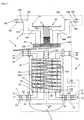
- Fig. 1 shows a schematic sectional view of a device 1 with a heat exchanger 2, which has an in particular hollow cylindrical, pressure-bearing jacket 80, the longitudinal or cylinder axis Z of which extends along the vertical Z, in relation to a state of the heat exchanger 1 arranged as intended.
- the jacket 80 delimits a jacket space M, in which a wound tube bundle 20 is arranged.
- This has a plurality of tubes 20a, which are wound in several layers around a core tube 100, the longitudinal axis of which coincides with the longitudinal axis of the jacket 80.
- the tube bundle 20 is thus arranged coaxially with the jacket 80.
- At least a first medium F ′ which flows upwards along the vertical Z, is fed into the tube space formed by the tube bundle 20.
- the jacket space M serves to hold a second medium in the form of a liquid F, which is applied to the at least one tube bundle 20 and flows downwards in the jacket space M along the vertical Z. Due to the design of the tube bundle 20 as a wound tube bundle 20, the first medium F 'is thus led to the liquid F in a cross-countercurrent.
- At least one optical waveguide 101 is provided, which extends helically for example in one of the tubes 20a - corresponding to the shape of the tube 20a - or is arranged outside such a tube 20a around which To measure the temperature in the heat exchanger 2 three-dimensionally.
- a large number of such optical waveguides 101 can be arranged in the individual tubes 20a or on the individual tubes 20a or in some other way in the jacket space M in order to be able to measure specific areas of the heat exchanger 2.
- the at least one optical waveguide 101 is preferably led out of the jacket space M and coupled to a measuring device 110, which is designed to evaluate light scattered back in the optical waveguide 101 in order to determine the temperature in the heat exchanger 2. Since a multiplicity of measurement points are obtained along the optical waveguide 101 on the basis of this measurement method, a one-dimensional arrangement of the at least one optical waveguide 101 can be used three-dimensional actual temperature distribution can be measured in real time. In order to be able to ensure optimal operation of the heat exchanger 2, a corresponding target temperature distribution of the tube bundle 20 is determined, which corresponds to such an optimized operation.
- said measuring device 110 is coupled to a control means 120 which is designed to regulate media F, F 'or flows S, S' guided on the pipe or shell side in such a way that the respectively measured actual temperature distribution corresponds to the desired target temperature distribution is approximated.
- a stream S of the liquid F introduced into the jacket 80 is collected, calmed and degassed in a pre-distributor 43.
- the pre-distributor 43 has a circumferential wall for receiving the liquid F, which wall extends from a floor running transversely to the longitudinal axis Z of the jacket 20.
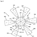
- the bottom of the prescaler 43 is connected via a down pipe 380 running in the core tube 100 to a main distributor 44 of the liquid distributor 40 in order to feed the latter with the flow S of the liquid F, the main distributor 44 for distributing the flow S of the liquid F over the whole Cross section of the jacket space M has a plurality of distributor arms 300 transversely to the vertical Z (cf. Fig.
- the distributor arms 300 each have a base with a plurality of through openings, so-called perforated bases, through which liquid F introduced into the distributor arms 300 can rain onto the tube bundle 20 arranged along the vertical Z below.
- the distribution and supply of part of the liquid F in the form of at least one further stream S ' is now carried out parallel to the (main) stream S on the jacket side.
- additional lines 481 to 484 are provided for conducting the further stream S '(or the further streams), which are led into the jacket space M via corresponding inlets / connecting pieces 281 to 284, and each have at least one outlet 485 via which the Liquid F can also be placed in a controllable manner onto the at least one tube bundle 20.
- said lines 481 to 484 each have an assigned valve 181 to 184, which can be regulated by means of control means 120, so that control means 120 can set the individual valves 181 to 184 in accordance with the current actual temperature distribution in such a way that the additional flow S ' of the liquid F is distributed to the tube bundle 20 in such a way that the continuously measured actual temperature distribution approaches the predetermined target temperature distribution.
- the lines 481 to 484 are led through the said passage areas 45 of the main distributor 44, the outlets 485 of the lines 481 to 484 being arranged above the tube bundle 20 are, in particular in such a way that the tube bundle 20 in the radial direction R of the jacket 80 or the tube bundle 20 can be acted upon separately with the liquid F in sections.
- the individual sections can encompass sections that are located radially further inward, whereby adjacent sections can also penetrate one another.
- the distributor arms 300 of the main distributor 44 which are designed in the form of a sector of a circle, can be of the type of Fig. 1 , which are separated from one another by said passage areas 45, for variably distributing the flow S of the liquid F in the radial direction R into a plurality of segments 351 to 353, each of which has at least one passage opening 370 through which the liquid F can rain on the tube bundle 20 underneath.
- a supply of liquid F into said segments 351 to 353 is now regulated separately for each of segments 351 to 353, for example by feeding each segment 351 to 353 via a downpipe that can be regulated by means of a valve (for example from a pre-distributor 43), the flow S of the liquid F in radial direction R of the jacket 80 or the tube bundle 20 can be variably distributed to a number of sections of the tube bundle 20 corresponding to the number of segments (see above).
- said control means 120 is correspondingly connected to said valves on the downpipe, so that they can be controlled in accordance with the instantaneous, in particular real-time, temperature distribution so that the actual temperature distribution approximates the target temperature distribution.
- the distributor arms 300 can be designed to apply liquid F to different sections of the tube bundle 20, for example by correspondingly distributing the through holes 371 of the distributor arms 300 along the radial direction R in accordance with Fig. 2 .
- the distributor arms 300 according to FIG Fig. 2 One through opening 371 each, which is displaced in the radial direction R with respect to the corresponding through openings 371 of the adjacent distributor arms 300.
- Other distributions of this type, in particular with a plurality of through holes per distributor arm 300, are also conceivable.
- the core tube 100 is divided into sections 381 to 386, so that a corresponding number of downpipes is formed, each of which is preferably designed to be controllable are (for example by means of valves) and in each case feed at least one assigned distributor arm 300 with the liquid F (cf. Fig. 2 ).
- a section 381 to 386 of the core tube 100 acts on the liquid F with more than one distributor arm 300, for example two distributor arms 300.
- Said down pipes 381 to 386 in turn can, for example, from a pre-distributor 43 according to Fig. 1 be fed.
- Said valves are in turn connected to the control means 120, so that the individual valves can be set as a function of the respective actual temperature distribution so that the currently measured actual temperature distribution approximates the predetermined target temperature distribution of the tube bundle 20.
- the tubes 20a are preferably coaxial with the jacket 80 of the heat exchanger 2 arranged tube bundle 20 is wound around the core tube 100 such that a plurality of sections R1, R2, R3 of the tube bundle 20 are formed, which are formed separately from one another and each encircle the core tube 100, the sections R1, R2, R3 embracing each other, but also each other can penetrate.
- the tubes 20a are preferably coaxial with the jacket 80 of the heat exchanger 2 arranged tube bundle 20 is wound around the core tube 100 such that a plurality of sections R1, R2, R3 of the tube bundle 20 are formed, which are formed separately from one another and each encircle the core tube 100, the sections R1, R2, R3 embracing each other, but also each other can penetrate.
- the tubes 20a are preferably coaxial with the jacket 80 of the heat exchanger 2 arranged tube bundle 20 is wound around the core tube 100 such that a plurality of sections R1, R2, R3 of the tube bundle 20 are formed, which are formed separately from one another and each encircle the core
- each section R1, R2, R3 can not only be supplied with the first medium separately via assigned inlets 51 to 56 at a lower end of the jacket 80 (in the present case, each section R1, R2, R3 has two inlets and without restriction of generality) Outlets; however, only one inlet or outlet can be provided per section), but the action on the pipe side can also be controlled via valves 71 to 76 assigned to inlets 51 to 56, which are correspondingly connected to control means 120 .
- the individual valves 71 to 76 are set by the control means 120 in such a way that the respective actual temperature distribution of the tube bundle 20 is adjusted to a desired target temperature distribution.
- the medium F 'introduced into the individual radial sections R1, R2, R3 can finally be withdrawn from the tube bundle 20 at an upper end of the jacket 80 via corresponding outlets 61 to 66 of the sections R1, R2, R3.
Landscapes
- Engineering & Computer Science (AREA)
- Physics & Mathematics (AREA)
- Thermal Sciences (AREA)
- Mechanical Engineering (AREA)
- General Engineering & Computer Science (AREA)
- General Physics & Mathematics (AREA)
- Heat-Exchange Devices With Radiators And Conduit Assemblies (AREA)
- Measuring Temperature Or Quantity Of Heat (AREA)
- Physical Or Chemical Processes And Apparatus (AREA)
- Control Of Temperature (AREA)
Claims (2)
- Procédé pour régler une distribution de température dans un échangeur de chaleur, dans lequel une distribution de température réelle dans l'échangeur de chaleur (2) est mesurée au moyen d'au moins une fibre optique (101) disposée dans l'échangeur de chaleur (2), en particulier sous la forme d'une fibre de verre, la lumière étant couplée dans l'au moins une fibre optique (101) et la lumière diffusée dans la fibre optique (101) étant évaluée pour déterminer la distribution de température réelle et l'échangeur de chaleur (2) présentant un faisceau de tubes (20) comprenant une pluralité de tubes (20a), qui sont disposés dans un espace d'enveloppe (M) de l'échangeur de chaleur (2) et la distribution de température réelle étant mesurée au moyen de l'au moins une fibre optique (101) disposée à l'intérieur d'un tube (20a) du faisceau de tubes (20) et/ou sur un côté extérieur d'un tube (20a) du faisceau de tubes (20) dans l'espace d'enveloppe (M) et l'échangeur de chaleur (2) étant conçu comme un échangeur de chaleur spiralé,
caractérisé en ce
qu'au moins un flux (S, S') d'un milieu fluide (F, F') guidé dans l'échangeur de chaleur (2) est réglé de manière à ce que la distribution de température réelle s'approche d'une distribution de température de consigne et- les tubes (20a) formant une pluralité de sections (R1, R2, R3) du faisceau de tubes (20) qui peuvent être chargées séparément avec ce milieu, les sections individuelles (R1, R2, R3) étant chacune chargées avec ce milieu (F') de manière à ce que la distribution de température réelle s'approche de la distribution de température de consigne,
ou- un flux (S, S') d'un milieu fluide (F) étant distribué dans l'espace d'enveloppe (M) sur le faisceau de tubes (20) de manière à ce que la distribution de température réelle s'approche de la distribution de température de consigne, le milieu fluide (F) étant distribué de manière variable sur le faisceau de tubes (20) dans une direction radiale (R) du faisceau de tubes (20) et/ou dans une direction circonférentielle (U) du faisceau de tubes (20), de sorte que la distribution de température réelle s'approche de la distribution de température de consigne. - Procédé selon la revendication 1, caractérisé en ce qu'une distribution de température réelle tridimensionnelle est mesurée en tant que distribution de température réelle.
Priority Applications (1)
| Application Number | Priority Date | Filing Date | Title |
|---|---|---|---|
| EP13774072.6A EP2906897B1 (fr) | 2012-10-09 | 2013-10-02 | Procédé pour régler une distribution de température dans un échangeur de chaleur |
Applications Claiming Priority (3)
| Application Number | Priority Date | Filing Date | Title |
|---|---|---|---|
| EP12006983 | 2012-10-09 | ||
| PCT/EP2013/002976 WO2014056588A1 (fr) | 2012-10-09 | 2013-10-02 | Procédé pour régler une distribution de température dans un caloporteur |
| EP13774072.6A EP2906897B1 (fr) | 2012-10-09 | 2013-10-02 | Procédé pour régler une distribution de température dans un échangeur de chaleur |
Publications (2)
| Publication Number | Publication Date |
|---|---|
| EP2906897A1 EP2906897A1 (fr) | 2015-08-19 |
| EP2906897B1 true EP2906897B1 (fr) | 2020-07-08 |
Family
ID=47088616
Family Applications (1)
| Application Number | Title | Priority Date | Filing Date |
|---|---|---|---|
| EP13774072.6A Active EP2906897B1 (fr) | 2012-10-09 | 2013-10-02 | Procédé pour régler une distribution de température dans un échangeur de chaleur |
Country Status (7)
| Country | Link |
|---|---|
| US (1) | US9766024B2 (fr) |
| EP (1) | EP2906897B1 (fr) |
| CN (1) | CN104884893B (fr) |
| AU (1) | AU2013329887B2 (fr) |
| MY (1) | MY182637A (fr) |
| RU (1) | RU2656223C2 (fr) |
| WO (1) | WO2014056588A1 (fr) |
Families Citing this family (14)
| Publication number | Priority date | Publication date | Assignee | Title |
|---|---|---|---|---|
| US9745069B2 (en) * | 2013-01-21 | 2017-08-29 | Hamilton Sundstrand Corporation | Air-liquid heat exchanger assembly having a bypass valve |
| EP3006875A1 (fr) * | 2014-10-09 | 2016-04-13 | Linde Aktiengesellschaft | Procédé de réglage d'un système d'échangeur thermique couplé et système d'échangeur thermique |
| DE102014018825A1 (de) | 2014-12-19 | 2016-06-23 | Man Diesel & Turbo Se | Faseroptische Temperaturmessung |
| WO2016188635A1 (fr) * | 2015-05-28 | 2016-12-01 | Linde Aktiengesellschaft | Procédé pour déterminer l'état d'un dispositif d'échange de chaleur |
| EP3128278B1 (fr) * | 2015-08-06 | 2018-06-20 | Linde Aktiengesellschaft | Amenee et extraction d'ecoulements tubulaires par temperature intermediaire pour des echangeurs de chaleur a bobines |
| DE102016000246A1 (de) * | 2016-01-12 | 2017-07-13 | Linde Aktiengesellschaft | Verfahren zur Bestimmung eines Dehnungslastwechsels eines Plattenwärmeübertragers |
| WO2017157533A1 (fr) * | 2016-03-16 | 2017-09-21 | Linde Aktiengesellschaft | Échangeur de chaleur de sécurité pour le réglage de la température |
| WO2017167458A1 (fr) * | 2016-03-30 | 2017-10-05 | Linde Aktiengesellschaft | Echangeur de chaleur à spirales |
| EP3367033A1 (fr) * | 2017-02-24 | 2018-08-29 | Linde Aktiengesellschaft | Échangeur thermique et procédé de distribution d'une phase liquide dans un échangeur thermique |
| DE102018003479A1 (de) * | 2018-04-27 | 2019-10-31 | Linde Aktiengesellschaft | Plattenwärmetauscher, verfahrenstechnische Anlage und Verfahren |
| WO2020035167A1 (fr) | 2018-08-14 | 2020-02-20 | Linde Aktiengesellschaft | Échangeur de chaleur enroulé, procédé de fabrication d'un échangeur de chaleur enroulé et procédé de mesure de température et/ou d'expansion dans un échangeur de chaleur enroulé |
| EP3719433A1 (fr) * | 2019-04-02 | 2020-10-07 | Linde GmbH | Distributeur de fluide réglable d'un échangeur de chaleur enroulé permettant de réaliser des différentes charges de fluide |
| EP3825639A1 (fr) * | 2019-11-19 | 2021-05-26 | Linde GmbH | Procédé de fonctionnement d'un échangeur de chaleur |
| CN111595180B (zh) * | 2020-05-27 | 2021-07-27 | 中国石油大学(华东) | 一种适用于flng的正弦波纹管型绕管式换热器 |
Family Cites Families (14)
| Publication number | Priority date | Publication date | Assignee | Title |
|---|---|---|---|---|
| DE2835334A1 (de) * | 1978-08-11 | 1980-02-21 | Linde Ag | Gewickelter waermetauscher |
| US4306612A (en) * | 1979-11-09 | 1981-12-22 | The Air Preheater Company, Inc. | Fiber optic sensing device |
| JPH0633865B2 (ja) * | 1990-07-11 | 1994-05-02 | 東京瓦斯株式会社 | Lng気化器に於ける海水流量制御方法 |
| US6357516B1 (en) * | 2000-02-02 | 2002-03-19 | York International Corporation | Plate heat exchanger assembly with enhanced heat transfer characteristics |
| DE102004001379B4 (de) * | 2004-01-09 | 2005-11-24 | Danfoss A/S | Mehrstufen-Wärmetauscheranordnung |
| WO2007009640A1 (fr) | 2005-07-22 | 2007-01-25 | Linde Aktiengesellschaft | Echangeur de chaleur enroule a parois d'insonorisation |
| BRPI0614699A2 (pt) | 2005-07-29 | 2011-04-12 | Linde Ag | trocador de calor enrolado consistindo em diferentes materiais |
| SE530902C2 (sv) | 2006-12-19 | 2008-10-14 | Alfa Laval Corp Ab | Sektionerad flödesanordning och förfarande för att reglera temperaturen i denna |
| DE102007021564A1 (de) * | 2007-05-08 | 2008-11-20 | Linde Ag | Verfahren zur Temperaturmessung in Anlagenteilen |
| DE102007021565A1 (de) * | 2007-05-08 | 2008-11-13 | Linde Ag | Wärmetauscher mit optischer Temperaturmessung |
| US20100037889A1 (en) * | 2008-08-12 | 2010-02-18 | Bradford White Corporation | Solar heating system with back-up heating |
| WO2010093920A2 (fr) * | 2009-02-13 | 2010-08-19 | Halliburton Energy Services, Inc. | Flux bidirectionnel et détection d'une température répartie dans des puits souterrains |
| CN102478371A (zh) * | 2010-11-29 | 2012-05-30 | 李文涛 | 换热器自动控制系统 |
| AU2012201798A1 (en) * | 2011-04-14 | 2012-11-01 | Linde Aktiengesellschaft | Heat exchanger with additional liquid control in shell space |
-
2013
- 2013-10-02 CN CN201380052313.5A patent/CN104884893B/zh active Active
- 2013-10-02 MY MYPI2015000912A patent/MY182637A/en unknown
- 2013-10-02 WO PCT/EP2013/002976 patent/WO2014056588A1/fr not_active Ceased
- 2013-10-02 EP EP13774072.6A patent/EP2906897B1/fr active Active
- 2013-10-02 AU AU2013329887A patent/AU2013329887B2/en active Active
- 2013-10-02 RU RU2015116266A patent/RU2656223C2/ru active
- 2013-10-02 US US14/434,512 patent/US9766024B2/en not_active Expired - Fee Related
Non-Patent Citations (1)
| Title |
|---|
| None * |
Also Published As
| Publication number | Publication date |
|---|---|
| RU2015116266A (ru) | 2016-12-10 |
| EP2906897A1 (fr) | 2015-08-19 |
| CN104884893B (zh) | 2018-01-23 |
| RU2656223C2 (ru) | 2018-06-01 |
| AU2013329887A1 (en) | 2015-04-16 |
| AU2013329887B2 (en) | 2018-02-01 |
| WO2014056588A1 (fr) | 2014-04-17 |
| US9766024B2 (en) | 2017-09-19 |
| MY182637A (en) | 2021-01-27 |
| US20150369548A1 (en) | 2015-12-24 |
| CN104884893A (zh) | 2015-09-02 |
Similar Documents
| Publication | Publication Date | Title |
|---|---|---|
| EP2906897B1 (fr) | Procédé pour régler une distribution de température dans un échangeur de chaleur | |
| EP2310155B1 (fr) | Mesure de la température dans une lingotière à l'aide d'un procédé de mesure à fibre optique | |
| EP2511642B1 (fr) | Echangeur thermique doté d'un réglage de liquide supplémentaire dans l'espace d'enveloppe | |
| DE3587641T2 (de) | Verteilter, gemäss raumauflösung aufgestellter dehnungsmesser mit optischer faser. | |
| EP3233261B1 (fr) | Mesure de température par fibre optique dans un lit de catalyseur | |
| DE102007021564A1 (de) | Verfahren zur Temperaturmessung in Anlagenteilen | |
| EP2483643B1 (fr) | Installation produisant des gas d'échappement, un bateau en particulier, avec détermination du volume de gaz d'échappement | |
| DE3136071C2 (de) | Verfahren zum Regeln von Parametern bei der Herstellung von Vorformlingen optischer Fasern | |
| EP2906919B1 (fr) | Mesure de température au moyen d'un guide d'ondes lumineuses dans un échangeur de chaleur à plaques | |
| DE3833602A1 (de) | Spektrometer zur gleichzeitigen intensitaetsmessung in verschiedenen spektralbereichen | |
| DE102016214887A1 (de) | Faseroptischer Sensor sowie Verfahren zu dessen Herstellung und Verwendung | |
| DE102015226571A1 (de) | Vorrichtung und Verfahren zur Wellenfrontanalyse | |
| WO2019020800A1 (fr) | Procédé et dispositif de mesure optique de surfaces au moyen d'un capteur confocal | |
| EP3784974B2 (fr) | Échangeur de chaleur en plaques, installation technique de procédé et procédé | |
| DE102007021565A1 (de) | Wärmetauscher mit optischer Temperaturmessung | |
| EP1012838A1 (fr) | Procede de regulation d'un processus d'application de revetement | |
| EP2720016A1 (fr) | Procédé de mesure d'un profil de température dans une colonne pour l'échange d'énergie et/ou de matière | |
| EP4025885B1 (fr) | Dispositif pour applications optiques | |
| WO2020035167A1 (fr) | Échangeur de chaleur enroulé, procédé de fabrication d'un échangeur de chaleur enroulé et procédé de mesure de température et/ou d'expansion dans un échangeur de chaleur enroulé | |
| WO2013178611A1 (fr) | Système de caractérisation optique de lentilles de fresnel | |
| DE102012005569A1 (de) | Wärmetauscher mit Sektionen | |
| DE102022101323A1 (de) | Laserschneideverfahren mit Einstellen der Fokuslage | |
| WO2021110297A1 (fr) | Dispositif d'éclairage de pièce, procédé de modification associé et procédé de mesure de la surface de la pièce | |
| WO2006079466A1 (fr) | Combinaison d'appareils destines a une mesure de concentration de matiere et a une mesure d'un profil de temperatures sur la base de reseaux de bragg a fibres dans des fibres optiques | |
| DE102009039101B4 (de) | Vorrichtung und Verfahren zur Messung von Kräften auf Walzen- oder Rollenoberflächen und/oder zur Messung von Temperaturen an Walzen- oder Rollenoberflächen |
Legal Events
| Date | Code | Title | Description |
|---|---|---|---|
| PUAI | Public reference made under article 153(3) epc to a published international application that has entered the european phase |
Free format text: ORIGINAL CODE: 0009012 |
|
| 17P | Request for examination filed |
Effective date: 20150402 |
|
| AK | Designated contracting states |
Kind code of ref document: A1 Designated state(s): AL AT BE BG CH CY CZ DE DK EE ES FI FR GB GR HR HU IE IS IT LI LT LU LV MC MK MT NL NO PL PT RO RS SE SI SK SM TR |
|
| AX | Request for extension of the european patent |
Extension state: BA ME |
|
| RIN1 | Information on inventor provided before grant (corrected) |
Inventor name: STEINBAUER, MANFRED Inventor name: MOLL, ANTON Inventor name: FERSTL, JOHANN Inventor name: FLUEGGEN, RAINER Inventor name: VON GEMMINGEN, ULRICH |
|
| DAX | Request for extension of the european patent (deleted) | ||
| 17Q | First examination report despatched |
Effective date: 20160718 |
|
| STAA | Information on the status of an ep patent application or granted ep patent |
Free format text: STATUS: EXAMINATION IS IN PROGRESS |
|
| GRAP | Despatch of communication of intention to grant a patent |
Free format text: ORIGINAL CODE: EPIDOSNIGR1 |
|
| STAA | Information on the status of an ep patent application or granted ep patent |
Free format text: STATUS: GRANT OF PATENT IS INTENDED |
|
| INTG | Intention to grant announced |
Effective date: 20200324 |
|
| GRAS | Grant fee paid |
Free format text: ORIGINAL CODE: EPIDOSNIGR3 |
|
| GRAA | (expected) grant |
Free format text: ORIGINAL CODE: 0009210 |
|
| STAA | Information on the status of an ep patent application or granted ep patent |
Free format text: STATUS: THE PATENT HAS BEEN GRANTED |
|
| RAP1 | Party data changed (applicant data changed or rights of an application transferred) |
Owner name: LINDE GMBH |
|
| AK | Designated contracting states |
Kind code of ref document: B1 Designated state(s): AL AT BE BG CH CY CZ DE DK EE ES FI FR GB GR HR HU IE IS IT LI LT LU LV MC MK MT NL NO PL PT RO RS SE SI SK SM TR |
|
| REG | Reference to a national code |
Ref country code: GB Ref legal event code: FG4D Free format text: NOT ENGLISH |
|
| REG | Reference to a national code |
Ref country code: AT Ref legal event code: REF Ref document number: 1288918 Country of ref document: AT Kind code of ref document: T Effective date: 20200715 Ref country code: CH Ref legal event code: EP |
|
| REG | Reference to a national code |
Ref country code: DE Ref legal event code: R096 Ref document number: 502013014895 Country of ref document: DE |
|
| REG | Reference to a national code |
Ref country code: IE Ref legal event code: FG4D Free format text: LANGUAGE OF EP DOCUMENT: GERMAN |
|
| REG | Reference to a national code |
Ref country code: NO Ref legal event code: T2 Effective date: 20200708 |
|
| REG | Reference to a national code |
Ref country code: LT Ref legal event code: MG4D |
|
| REG | Reference to a national code |
Ref country code: NL Ref legal event code: MP Effective date: 20200708 |
|
| PG25 | Lapsed in a contracting state [announced via postgrant information from national office to epo] |
Ref country code: GR Free format text: LAPSE BECAUSE OF FAILURE TO SUBMIT A TRANSLATION OF THE DESCRIPTION OR TO PAY THE FEE WITHIN THE PRESCRIBED TIME-LIMIT Effective date: 20201009 Ref country code: FI Free format text: LAPSE BECAUSE OF FAILURE TO SUBMIT A TRANSLATION OF THE DESCRIPTION OR TO PAY THE FEE WITHIN THE PRESCRIBED TIME-LIMIT Effective date: 20200708 Ref country code: SE Free format text: LAPSE BECAUSE OF FAILURE TO SUBMIT A TRANSLATION OF THE DESCRIPTION OR TO PAY THE FEE WITHIN THE PRESCRIBED TIME-LIMIT Effective date: 20200708 Ref country code: PT Free format text: LAPSE BECAUSE OF FAILURE TO SUBMIT A TRANSLATION OF THE DESCRIPTION OR TO PAY THE FEE WITHIN THE PRESCRIBED TIME-LIMIT Effective date: 20201109 Ref country code: HR Free format text: LAPSE BECAUSE OF FAILURE TO SUBMIT A TRANSLATION OF THE DESCRIPTION OR TO PAY THE FEE WITHIN THE PRESCRIBED TIME-LIMIT Effective date: 20200708 Ref country code: LT Free format text: LAPSE BECAUSE OF FAILURE TO SUBMIT A TRANSLATION OF THE DESCRIPTION OR TO PAY THE FEE WITHIN THE PRESCRIBED TIME-LIMIT Effective date: 20200708 Ref country code: ES Free format text: LAPSE BECAUSE OF FAILURE TO SUBMIT A TRANSLATION OF THE DESCRIPTION OR TO PAY THE FEE WITHIN THE PRESCRIBED TIME-LIMIT Effective date: 20200708 Ref country code: BG Free format text: LAPSE BECAUSE OF FAILURE TO SUBMIT A TRANSLATION OF THE DESCRIPTION OR TO PAY THE FEE WITHIN THE PRESCRIBED TIME-LIMIT Effective date: 20201008 |
|
| PG25 | Lapsed in a contracting state [announced via postgrant information from national office to epo] |
Ref country code: IS Free format text: LAPSE BECAUSE OF FAILURE TO SUBMIT A TRANSLATION OF THE DESCRIPTION OR TO PAY THE FEE WITHIN THE PRESCRIBED TIME-LIMIT Effective date: 20201108 Ref country code: LV Free format text: LAPSE BECAUSE OF FAILURE TO SUBMIT A TRANSLATION OF THE DESCRIPTION OR TO PAY THE FEE WITHIN THE PRESCRIBED TIME-LIMIT Effective date: 20200708 Ref country code: PL Free format text: LAPSE BECAUSE OF FAILURE TO SUBMIT A TRANSLATION OF THE DESCRIPTION OR TO PAY THE FEE WITHIN THE PRESCRIBED TIME-LIMIT Effective date: 20200708 Ref country code: RS Free format text: LAPSE BECAUSE OF FAILURE TO SUBMIT A TRANSLATION OF THE DESCRIPTION OR TO PAY THE FEE WITHIN THE PRESCRIBED TIME-LIMIT Effective date: 20200708 |
|
| PG25 | Lapsed in a contracting state [announced via postgrant information from national office to epo] |
Ref country code: NL Free format text: LAPSE BECAUSE OF FAILURE TO SUBMIT A TRANSLATION OF THE DESCRIPTION OR TO PAY THE FEE WITHIN THE PRESCRIBED TIME-LIMIT Effective date: 20200708 |
|
| REG | Reference to a national code |
Ref country code: DE Ref legal event code: R097 Ref document number: 502013014895 Country of ref document: DE |
|
| PG25 | Lapsed in a contracting state [announced via postgrant information from national office to epo] |
Ref country code: SM Free format text: LAPSE BECAUSE OF FAILURE TO SUBMIT A TRANSLATION OF THE DESCRIPTION OR TO PAY THE FEE WITHIN THE PRESCRIBED TIME-LIMIT Effective date: 20200708 Ref country code: RO Free format text: LAPSE BECAUSE OF FAILURE TO SUBMIT A TRANSLATION OF THE DESCRIPTION OR TO PAY THE FEE WITHIN THE PRESCRIBED TIME-LIMIT Effective date: 20200708 Ref country code: IT Free format text: LAPSE BECAUSE OF FAILURE TO SUBMIT A TRANSLATION OF THE DESCRIPTION OR TO PAY THE FEE WITHIN THE PRESCRIBED TIME-LIMIT Effective date: 20200708 Ref country code: EE Free format text: LAPSE BECAUSE OF FAILURE TO SUBMIT A TRANSLATION OF THE DESCRIPTION OR TO PAY THE FEE WITHIN THE PRESCRIBED TIME-LIMIT Effective date: 20200708 Ref country code: CZ Free format text: LAPSE BECAUSE OF FAILURE TO SUBMIT A TRANSLATION OF THE DESCRIPTION OR TO PAY THE FEE WITHIN THE PRESCRIBED TIME-LIMIT Effective date: 20200708 Ref country code: DK Free format text: LAPSE BECAUSE OF FAILURE TO SUBMIT A TRANSLATION OF THE DESCRIPTION OR TO PAY THE FEE WITHIN THE PRESCRIBED TIME-LIMIT Effective date: 20200708 |
|
| REG | Reference to a national code |
Ref country code: DE Ref legal event code: R119 Ref document number: 502013014895 Country of ref document: DE |
|
| PLBE | No opposition filed within time limit |
Free format text: ORIGINAL CODE: 0009261 |
|
| STAA | Information on the status of an ep patent application or granted ep patent |
Free format text: STATUS: NO OPPOSITION FILED WITHIN TIME LIMIT |
|
| PG25 | Lapsed in a contracting state [announced via postgrant information from national office to epo] |
Ref country code: AL Free format text: LAPSE BECAUSE OF FAILURE TO SUBMIT A TRANSLATION OF THE DESCRIPTION OR TO PAY THE FEE WITHIN THE PRESCRIBED TIME-LIMIT Effective date: 20200708 |
|
| REG | Reference to a national code |
Ref country code: CH Ref legal event code: PL |
|
| 26N | No opposition filed |
Effective date: 20210409 |
|
| GBPC | Gb: european patent ceased through non-payment of renewal fee |
Effective date: 20201008 |
|
| PG25 | Lapsed in a contracting state [announced via postgrant information from national office to epo] |
Ref country code: SK Free format text: LAPSE BECAUSE OF FAILURE TO SUBMIT A TRANSLATION OF THE DESCRIPTION OR TO PAY THE FEE WITHIN THE PRESCRIBED TIME-LIMIT Effective date: 20200708 Ref country code: MC Free format text: LAPSE BECAUSE OF FAILURE TO SUBMIT A TRANSLATION OF THE DESCRIPTION OR TO PAY THE FEE WITHIN THE PRESCRIBED TIME-LIMIT Effective date: 20200708 Ref country code: LU Free format text: LAPSE BECAUSE OF NON-PAYMENT OF DUE FEES Effective date: 20201002 |
|
| REG | Reference to a national code |
Ref country code: BE Ref legal event code: MM Effective date: 20201031 |
|
| PG25 | Lapsed in a contracting state [announced via postgrant information from national office to epo] |
Ref country code: FR Free format text: LAPSE BECAUSE OF NON-PAYMENT OF DUE FEES Effective date: 20201031 Ref country code: DE Free format text: LAPSE BECAUSE OF NON-PAYMENT OF DUE FEES Effective date: 20210501 |
|
| PG25 | Lapsed in a contracting state [announced via postgrant information from national office to epo] |
Ref country code: SI Free format text: LAPSE BECAUSE OF FAILURE TO SUBMIT A TRANSLATION OF THE DESCRIPTION OR TO PAY THE FEE WITHIN THE PRESCRIBED TIME-LIMIT Effective date: 20200708 Ref country code: GB Free format text: LAPSE BECAUSE OF NON-PAYMENT OF DUE FEES Effective date: 20201008 Ref country code: LI Free format text: LAPSE BECAUSE OF NON-PAYMENT OF DUE FEES Effective date: 20201031 Ref country code: CH Free format text: LAPSE BECAUSE OF NON-PAYMENT OF DUE FEES Effective date: 20201031 Ref country code: BE Free format text: LAPSE BECAUSE OF NON-PAYMENT OF DUE FEES Effective date: 20201031 |
|
| PG25 | Lapsed in a contracting state [announced via postgrant information from national office to epo] |
Ref country code: IE Free format text: LAPSE BECAUSE OF NON-PAYMENT OF DUE FEES Effective date: 20201002 |
|
| REG | Reference to a national code |
Ref country code: AT Ref legal event code: MM01 Ref document number: 1288918 Country of ref document: AT Kind code of ref document: T Effective date: 20201002 |
|
| PG25 | Lapsed in a contracting state [announced via postgrant information from national office to epo] |
Ref country code: AT Free format text: LAPSE BECAUSE OF NON-PAYMENT OF DUE FEES Effective date: 20201002 |
|
| PG25 | Lapsed in a contracting state [announced via postgrant information from national office to epo] |
Ref country code: TR Free format text: LAPSE BECAUSE OF FAILURE TO SUBMIT A TRANSLATION OF THE DESCRIPTION OR TO PAY THE FEE WITHIN THE PRESCRIBED TIME-LIMIT Effective date: 20200708 Ref country code: MT Free format text: LAPSE BECAUSE OF FAILURE TO SUBMIT A TRANSLATION OF THE DESCRIPTION OR TO PAY THE FEE WITHIN THE PRESCRIBED TIME-LIMIT Effective date: 20200708 Ref country code: CY Free format text: LAPSE BECAUSE OF FAILURE TO SUBMIT A TRANSLATION OF THE DESCRIPTION OR TO PAY THE FEE WITHIN THE PRESCRIBED TIME-LIMIT Effective date: 20200708 |
|
| PG25 | Lapsed in a contracting state [announced via postgrant information from national office to epo] |
Ref country code: MK Free format text: LAPSE BECAUSE OF FAILURE TO SUBMIT A TRANSLATION OF THE DESCRIPTION OR TO PAY THE FEE WITHIN THE PRESCRIBED TIME-LIMIT Effective date: 20200708 |
|
| P01 | Opt-out of the competence of the unified patent court (upc) registered |
Effective date: 20230525 |
|
| PGFP | Annual fee paid to national office [announced via postgrant information from national office to epo] |
Ref country code: NO Payment date: 20251022 Year of fee payment: 13 |