EP2906897B1 - Method for controlling a temperature distribution in a heat exchanger - Google Patents
Method for controlling a temperature distribution in a heat exchanger Download PDFInfo
- Publication number
- EP2906897B1 EP2906897B1 EP13774072.6A EP13774072A EP2906897B1 EP 2906897 B1 EP2906897 B1 EP 2906897B1 EP 13774072 A EP13774072 A EP 13774072A EP 2906897 B1 EP2906897 B1 EP 2906897B1
- Authority
- EP
- European Patent Office
- Prior art keywords
- temperature distribution
- tube bundle
- heat exchanger
- actual temperature
- liquid
- Prior art date
- Legal status (The legal status is an assumption and is not a legal conclusion. Google has not performed a legal analysis and makes no representation as to the accuracy of the status listed.)
- Active
Links
Images
Classifications
-
- F—MECHANICAL ENGINEERING; LIGHTING; HEATING; WEAPONS; BLASTING
- F28—HEAT EXCHANGE IN GENERAL
- F28F—DETAILS OF HEAT-EXCHANGE AND HEAT-TRANSFER APPARATUS, OF GENERAL APPLICATION
- F28F27/00—Control arrangements or safety devices specially adapted for heat-exchange or heat-transfer apparatus
- F28F27/02—Control arrangements or safety devices specially adapted for heat-exchange or heat-transfer apparatus for controlling the distribution of heat-exchange media between different channels
-
- F—MECHANICAL ENGINEERING; LIGHTING; HEATING; WEAPONS; BLASTING
- F25—REFRIGERATION OR COOLING; COMBINED HEATING AND REFRIGERATION SYSTEMS; HEAT PUMP SYSTEMS; MANUFACTURE OR STORAGE OF ICE; LIQUEFACTION SOLIDIFICATION OF GASES
- F25J—LIQUEFACTION, SOLIDIFICATION OR SEPARATION OF GASES OR GASEOUS OR LIQUEFIED GASEOUS MIXTURES BY PRESSURE AND COLD TREATMENT OR BY BRINGING THEM INTO THE SUPERCRITICAL STATE
- F25J5/00—Arrangements of cold exchangers or cold accumulators in separation or liquefaction plants
- F25J5/002—Arrangements of cold exchangers or cold accumulators in separation or liquefaction plants for continuously recuperating cold, i.e. in a so-called recuperative heat exchanger
-
- F—MECHANICAL ENGINEERING; LIGHTING; HEATING; WEAPONS; BLASTING
- F28—HEAT EXCHANGE IN GENERAL
- F28D—HEAT-EXCHANGE APPARATUS, NOT PROVIDED FOR IN ANOTHER SUBCLASS, IN WHICH THE HEAT-EXCHANGE MEDIA DO NOT COME INTO DIRECT CONTACT
- F28D7/00—Heat-exchange apparatus having stationary tubular conduit assemblies for both heat-exchange media, the media being in contact with different sides of a conduit wall
- F28D7/02—Heat-exchange apparatus having stationary tubular conduit assemblies for both heat-exchange media, the media being in contact with different sides of a conduit wall the conduits being helically coiled
- F28D7/024—Heat-exchange apparatus having stationary tubular conduit assemblies for both heat-exchange media, the media being in contact with different sides of a conduit wall the conduits being helically coiled the conduits of only one medium being helically coiled tubes, the coils having a cylindrical configuration
-
- F—MECHANICAL ENGINEERING; LIGHTING; HEATING; WEAPONS; BLASTING
- F28—HEAT EXCHANGE IN GENERAL
- F28D—HEAT-EXCHANGE APPARATUS, NOT PROVIDED FOR IN ANOTHER SUBCLASS, IN WHICH THE HEAT-EXCHANGE MEDIA DO NOT COME INTO DIRECT CONTACT
- F28D7/00—Heat-exchange apparatus having stationary tubular conduit assemblies for both heat-exchange media, the media being in contact with different sides of a conduit wall
- F28D7/16—Heat-exchange apparatus having stationary tubular conduit assemblies for both heat-exchange media, the media being in contact with different sides of a conduit wall the conduits being arranged in parallel spaced relation
-
- F—MECHANICAL ENGINEERING; LIGHTING; HEATING; WEAPONS; BLASTING
- F28—HEAT EXCHANGE IN GENERAL
- F28D—HEAT-EXCHANGE APPARATUS, NOT PROVIDED FOR IN ANOTHER SUBCLASS, IN WHICH THE HEAT-EXCHANGE MEDIA DO NOT COME INTO DIRECT CONTACT
- F28D9/00—Heat-exchange apparatus having stationary plate-like or laminated conduit assemblies for both heat-exchange media, the media being in contact with different sides of a conduit wall
- F28D9/0062—Heat-exchange apparatus having stationary plate-like or laminated conduit assemblies for both heat-exchange media, the media being in contact with different sides of a conduit wall the conduits for one heat-exchange medium being formed by spaced plates with inserted elements
- F28D9/0068—Heat-exchange apparatus having stationary plate-like or laminated conduit assemblies for both heat-exchange media, the media being in contact with different sides of a conduit wall the conduits for one heat-exchange medium being formed by spaced plates with inserted elements with means for changing flow direction of one heat exchange medium, e.g. using deflecting zones
-
- F—MECHANICAL ENGINEERING; LIGHTING; HEATING; WEAPONS; BLASTING
- F28—HEAT EXCHANGE IN GENERAL
- F28F—DETAILS OF HEAT-EXCHANGE AND HEAT-TRANSFER APPARATUS, OF GENERAL APPLICATION
- F28F27/00—Control arrangements or safety devices specially adapted for heat-exchange or heat-transfer apparatus
-
- G—PHYSICS
- G01—MEASURING; TESTING
- G01K—MEASURING TEMPERATURE; MEASURING QUANTITY OF HEAT; THERMALLY-SENSITIVE ELEMENTS NOT OTHERWISE PROVIDED FOR
- G01K11/00—Measuring temperature based upon physical or chemical changes not covered by groups G01K3/00, G01K5/00, G01K7/00 or G01K9/00
- G01K11/32—Measuring temperature based upon physical or chemical changes not covered by groups G01K3/00, G01K5/00, G01K7/00 or G01K9/00 using changes in transmittance, scattering or luminescence in optical fibres
-
- F—MECHANICAL ENGINEERING; LIGHTING; HEATING; WEAPONS; BLASTING
- F25—REFRIGERATION OR COOLING; COMBINED HEATING AND REFRIGERATION SYSTEMS; HEAT PUMP SYSTEMS; MANUFACTURE OR STORAGE OF ICE; LIQUEFACTION SOLIDIFICATION OF GASES
- F25J—LIQUEFACTION, SOLIDIFICATION OR SEPARATION OF GASES OR GASEOUS OR LIQUEFIED GASEOUS MIXTURES BY PRESSURE AND COLD TREATMENT OR BY BRINGING THEM INTO THE SUPERCRITICAL STATE
- F25J2210/00—Processes characterised by the type or other details of the feed stream
- F25J2210/06—Splitting of the feed stream, e.g. for treating or cooling in different ways
-
- F—MECHANICAL ENGINEERING; LIGHTING; HEATING; WEAPONS; BLASTING
- F25—REFRIGERATION OR COOLING; COMBINED HEATING AND REFRIGERATION SYSTEMS; HEAT PUMP SYSTEMS; MANUFACTURE OR STORAGE OF ICE; LIQUEFACTION SOLIDIFICATION OF GASES
- F25J—LIQUEFACTION, SOLIDIFICATION OR SEPARATION OF GASES OR GASEOUS OR LIQUEFIED GASEOUS MIXTURES BY PRESSURE AND COLD TREATMENT OR BY BRINGING THEM INTO THE SUPERCRITICAL STATE
- F25J2280/00—Control of the process or apparatus
- F25J2280/02—Control in general, load changes, different modes ("runs"), measurements
-
- F—MECHANICAL ENGINEERING; LIGHTING; HEATING; WEAPONS; BLASTING
- F25—REFRIGERATION OR COOLING; COMBINED HEATING AND REFRIGERATION SYSTEMS; HEAT PUMP SYSTEMS; MANUFACTURE OR STORAGE OF ICE; LIQUEFACTION SOLIDIFICATION OF GASES
- F25J—LIQUEFACTION, SOLIDIFICATION OR SEPARATION OF GASES OR GASEOUS OR LIQUEFIED GASEOUS MIXTURES BY PRESSURE AND COLD TREATMENT OR BY BRINGING THEM INTO THE SUPERCRITICAL STATE
- F25J2290/00—Other details not covered by groups F25J2200/00 - F25J2280/00
- F25J2290/50—Arrangement of multiple equipments fulfilling the same process step in parallel
-
- F—MECHANICAL ENGINEERING; LIGHTING; HEATING; WEAPONS; BLASTING
- F25—REFRIGERATION OR COOLING; COMBINED HEATING AND REFRIGERATION SYSTEMS; HEAT PUMP SYSTEMS; MANUFACTURE OR STORAGE OF ICE; LIQUEFACTION SOLIDIFICATION OF GASES
- F25J—LIQUEFACTION, SOLIDIFICATION OR SEPARATION OF GASES OR GASEOUS OR LIQUEFIED GASEOUS MIXTURES BY PRESSURE AND COLD TREATMENT OR BY BRINGING THEM INTO THE SUPERCRITICAL STATE
- F25J2290/00—Other details not covered by groups F25J2200/00 - F25J2280/00
- F25J2290/90—Details about safety operation of the installation
Definitions
- the invention relates to a method for regulating a temperature distribution in a wound heat exchanger.
- Such wound heat exchangers are known from the prior art and are used for indirect heat exchange between at least two fluid media.
- a wound heat exchanger In the case of a wound heat exchanger, a plurality of tubes, which form a tube bundle, are helically wound around a core tube, the tube bundle being enclosed by a pressure-carrying jacket which defines a jacket space surrounding the tube bundle for receiving one medium, the other medium being in the said tube bundle is guided so that the two media can enter into said direct heat exchange.
- the core tube extends in particular along a longitudinal axis, which - with reference to an intended state of the heat exchanger or the jacket - coincides with the vertical.
- a wound heat exchanger is for example from the WO 2007/014 617 or.
- DE 10 2007 021 564 A1 a method for temperature measurement in plant parts of the petrochemical industry or plants for air generation, wherein optical signals of at least one optical fiber located inside the plant parts are evaluated. Furthermore describes the DE 10 2007 021 565 A1 temperature measurement using light guides.
- the EP 2511642 A2 also describes the use of optical fibers for temperature measurement.
- the present invention is based on the problem of specifying a method for temperature control in a wound heat exchanger, which enables energy-optimized operation.
- a measuring device is preferably connected to the at least one optical waveguide, which is set up and provided to measure the actual temperature distribution in the heat exchanger by means of said optical waveguide.
- Said measuring device is preferably designed for this purpose or is used to introduce light or optical signals into the at least one optical waveguide and to evaluate light scattered back into the optical waveguide in a known manner.
- the measuring device is set up and provided for evaluating light backscattered by the at least one optical waveguide, which is produced by Raman scattering of the light introduced into the light guide.
- optical waveguides are usually made of doped quartz glass (amorphous solid-body structure, consisting mainly of silicon dioxide).
- amorphous solid-body structure consisting mainly of silicon dioxide.
- lattice vibrations are induced via thermal effects.
- Such lattice vibrations are temperature-dependent.
- Light that strikes the molecules or particles in the light guide therefore interacts with the electrons of the molecules. This interaction is also known as Raman scattering.
- the backscattered light can be divided into three spectral groups.
- the measuring device is therefore preferably designed to determine the intensity ratio to calculate between Stokes and Anti-Stokes components, the measuring device preferably being designed to calculate a Fourier transformation of these two backscattered components and to compare them with a Fourier transformation of a reference signal.
- the intensities of the two components over the length of the optical waveguide are obtained from this. The temperature for each point of the optical waveguide can thus be determined by comparing the two intensities.
- the temperature is determined by evaluating the Rayleigh scatter.
- the measuring device preferably has a coherent frequency range reflectometer (also referred to as c-OFDR, for coherent optical frequency domain reflectometer), in which light from a tunable laser is coupled into a Mach-Zehnder interferometer, which splits the light over two distances, whereby the optical waveguide forms one section and the other section is a reference section of known length.
- the Rayleigh scattered light from the optical waveguide is overlaid with the light component from the reference path and detected.
- a periodic signal is generated at the detector, the frequency of which depends on the scattering location of the optical waveguide.
- the individual frequencies of this signal which can be obtained via a Fourier transformation, thus correspond to the scattering locations in the optical waveguide; the amplitude of their frequency component indicates the intensity of the respective reflection. Resolutions ⁇ 0.1 mm can be achieved here.
- the Rayleigh radiation in an optical waveguide arises from elastic scattering processes at local effects / disturbances of the optical waveguide. If such a glass fiber is scanned by means of c-OFDR, a characteristic, fluctuating intensity curve of the Rayleigh scattering along the glass fiber results, which is spatially stretched or compressed when there is a change in temperature (change in the spatial expansion of the fiber), which causes the temperature can be calculated along the fiber.
- the measuring device is accordingly preferably configured to split the signal along the glass fiber into adjacent segments (eg ⁇ 1 mm) and to transform the corresponding signal into the frequency domain. For each segment there is a fluctuating reflection pattern depending on the frequency.
- the measuring device is preferably designed to determine the z, local) temperature of the glass fiber or the optical waveguide using the respective frequency shift.
- the temperature measurement is carried out by evaluating optical signals such as those produced by Brillouin scattering of the optical waveguide.
- the temperature measurement is based on the spatially resolved determination of the reference frequency between the primary light wave introduced into the optical fiber and the wave induced and backscattered as a result of Brillouin scattering in the optical fiber, the frequency of which depends on the temperature compared to the primary wave is reduced.
- the measuring device is therefore preferably designed to introduce a pulse-shaped primary light wave into the light guide and to detect the backscattered light in a time-resolved manner for different frequency differences and to determine the frequency shift based on the temperature change based on the temperature change with knowledge of the pulse transit time.
- the temperature at any point on the optical waveguide can be determined by evaluating the backscattered optical signals.
- the temperature by evaluating optical signals as they arise from scattering on the Bragg grating.
- Bragg gratings are optical band filters inscribed in the optical fiber, which can be placed almost any number of times in the optical fiber.
- the center wave number of the band stop results from the Bragg condition.
- the spectral width of the band stop depends on the temperature.
- the measuring device is then designed accordingly to determine the temperature at the respective point of the Bragg grating over the width of the band stop, given the grating length and refractive index using the optical waveguide.
- the actual temperature distribution can preferably be measured as a three-dimensional actual temperature distribution or as a three-dimensional actual temperature profile become.
- the at least one optical waveguide or a plurality of such optical waveguides is laid along the desired measurement locations, so that the at least one optical waveguide or a plurality of such optical waveguides extend from measurement location to measurement location.
- the measuring locations in the optical waveguide are very close to one another, since the aforementioned evaluation methods have a comparatively high spatial resolution.
- the heat exchanger has a tube bundle with a large number of tubes which are arranged in a pressure-bearing jacket space of the heat exchanger, the said actual temperature distribution preferably being determined by means of at least one optical waveguide which is arranged in the interior of a tube of the heat exchanger or by means of an optical waveguide, which is alternatively or additionally arranged on an outside of a tube of the heat exchanger in the jacket space of the heat exchanger.
- each of the tubes of the tube bundle of the heat exchanger with an optical waveguide running in the respective tube and / or on the respective tube, which are then preferably brought together and coupled into the measuring device described above.
- Said tubes of the tube bundle of the heat exchanger preferably form a plurality of sections of the tube bundle that can be fed separately with the said medium, the individual sections being sent with a flow of the medium that approximates the actual temperature distribution to the target temperature distribution.
- Sections are preferably radial sections, ie the tubes of the tube bundle are wrapped around the assigned core tube in such a way that at least one first section of the tube bundle surrounding the core tube and a separate second portion of the tube bundle surrounding the core tube are formed, which surrounds the first section or at least partially penetrates it, the two sections each having at least one assigned inlet, so that the two sections can be sent separately with that medium (so-called pipe-side regulation).
- the tube bundle can be divided into any number of individual, separately feedable sections in this way are, which lie one above the other in the radial direction of the tube bundle or at least partially penetrate each other.
- the feed of said medium via the inlet of the first section is then preferably regulated separately from the feed of the medium via the inlet of the second section.
- the control means preferably comprises at least one valve for the inlet of the first section and one valve for the inlet of the second section. The same applies to any number of sections of the tube bundle. Furthermore, said sections each have at least one assigned outlet for discharging the medium from the respective section of the tube bundle.
- a stream of a liquid medium is distributed in the jacket space to the said tube bundle in such a way that the actual temperature distribution is approximated to the target temperature distribution (so-called jacket-side regulation).
- Such a variable liquid distribution in the jacket space is preferably carried out in the method according to the invention with a liquid distributor arranged above the tube bundle for distributing said flow in the jacket space.
- a regulating means is preferably provided which is designed to regulate the distribution of said flow of liquid in the jacket space.
- the regulating means can be set up and provided to regulate the distribution of an additional, further flow of the liquid carried in the jacket space in the jacket room.
- the said flow and / or that further flow of the liquid medium in a radial direction of the jacket or the tube bundle is preferably variably distributed at least to a first and a second section of the tube bundle and / or in a circumferential direction of the jacket or tube bundle, so that the measured actual temperature distributions are adjusted according to a predetermined target temperature distribution.
- a region or section of the tube bundle located radially further outside can receive more liquid within a certain period of time than a region or section located further inside.
- liquid can be applied variably to the tube bundle along the circumferential direction.
- the method according to the invention is preferably carried out with a device which has a wound heat exchanger, and at least one optical waveguide arranged in the heat exchanger for measuring an in particular three-dimensional actual temperature distribution of the heat exchanger, and a measuring device connected to the at least one optical waveguide, which is set up and provided for this purpose
- the device further comprising regulating means for regulating at least one current carried in the heat exchanger in such a way that the actual temperature distribution is approximated to a predefined target temperature distribution.
- the wound heat exchanger has a wound tube bundle with a plurality of tubes which are wound in several layers around a core tube in a jacket space of the heat exchanger, the at least one optical waveguide in the interior of a tube of the wound tube bundle of the heat exchanger or on an outside of the tube of the wound tube bundle of the heat exchanger is arranged in the jacket space.
- each tube of the heat exchanger can be equipped with an optical waveguide running in the tube and / or on the outside of the tube, those optical waveguides then being brought together and coupled to the measuring device.
- Said tubes of the heat exchanger preferably form a plurality of sections of the tube bundle that can be fed separately with that medium, whereby these individual sections are each loaded with the said flow of the medium in such a way that the measured actual temperature distribution is approximated to the desired target temperature distribution (so-called pipe-side regulation).
- the tubes of the tube bundle are preferably wound around the core tube of the wound heat exchanger in such a way that at least one first section of the tube bundle encircling the core tube and a separate second section of the tube bundle encircling the core tube, which surrounds or at least partially penetrates the first section, is formed, the two sections each having at least one assigned inlet, so that the both sections can be loaded separately with that medium. Any number of such sections can of course be provided here.
- the regulating means is preferably designed to regulate the feed of the medium via the inlet of the first section separately from the feed of the medium via the inlet of the second section.
- the control means comprises at least one valve for the inlet of the first section and one valve for the inlet of the second section.
- the individual sections each have at least one assigned outlet for discharging the first medium from the respective section of the tube bundle.
- a jacket-side control can also be provided in the case of a heat exchanger in the form of a wound heat exchanger.
- the device is preferably designed to variably distribute a flow of a liquid medium in the jacket space over the tube bundle in such a way that the actual temperature distribution is approximated to the target temperature distribution.
- a regulation can, as already explained at the beginning, be regulated via a liquid distributor or an additional introduction of flows into the jacket space.
- a variant of the device provides a liquid distributor for distributing said flow in the jacket space, which is arranged in particular above the tube bundle in the jacket space.
- the control means is in particular designed to regulate the distribution of said flow in the jacket space and / or to regulate the distribution of an additional, further flow of the liquid medium in the jacket space in the jacket space.
- the liquid distributor can have a main distributor above the tube bundle for receiving the liquid medium to be distributed of the said stream, the main distributor preferably having through-openings through which the medium can be applied to the tube bundle.
- the control means in particular for regulating the distribution of the further flow of the liquid, at least one valve for the said line having.
- the main distributor can have at least one passage area through which tubes of the tube bundle are passed, whereby this passage region can be limited in particular by two distributor arms of the main distributor, via which the liquid or the medium can be applied to the tube bundle.
- said at least one line can be led through the at least one passage area. Distribution can thus be carried out via the main distributor and also via the additional lines.
- a plurality of such lines, each with at least one outlet, are preferably provided, via which the further flow of the liquid can be regulatedly applied to the tube bundle, the outlets being distributed over the cross section of the jacket space such that the further flow of the liquid is in a radial direction
- the direction of the jacket can be variably distributed to at least a first and a second section of the tube bundle (or to any number of sections) and / or a circumferential direction of the jacket, in order in particular to adapt the repeatedly measured actual temperature distribution to a predefined target temperature distribution.
- the main distributor of the liquid distributor has a plurality of distributor arms, which in particular each extend in the radial direction of the jacket or the core tube or also the tube bundle.
- the distributor arms for variably distributing the flow of the liquid in the radial direction are divided into at least two separate segments, each of which has at least one through-opening through which liquid can be applied to the tube bundle, the control means preferably being set up for this and it is provided to separately regulate a supply of liquid ketone into the two segments, so that the liquid in the radial direction of the Jacket can be variably distributed on at least a first and a second section of the tube bundle. The same applies to any number of sections.
- At least one distributor arm is set up and provided to apply liquid to a first section along the radial direction of the shell, and that at least one other distributor arm is set up to set up a different second one along the radial direction of the shell
- the two distributor arms for distributing the liquid to the two sections each have at least one through opening through which liquid can be applied to the tube bundle, those through openings being positioned differently along the radial direction
- a plurality of downpipes is provided, with a downpipe acting on at least one, in particular two, distributor arms with liquid, and in particular the downpipes being arranged in the core tube are or are formed by dividing the core tube into sections.
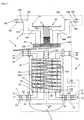
- Fig. 1 shows a schematic sectional view of a device 1 with a heat exchanger 2, which has an in particular hollow cylindrical, pressure-bearing jacket 80, the longitudinal or cylinder axis Z of which extends along the vertical Z, in relation to a state of the heat exchanger 1 arranged as intended.
- the jacket 80 delimits a jacket space M, in which a wound tube bundle 20 is arranged.
- This has a plurality of tubes 20a, which are wound in several layers around a core tube 100, the longitudinal axis of which coincides with the longitudinal axis of the jacket 80.
- the tube bundle 20 is thus arranged coaxially with the jacket 80.
- At least a first medium F ′ which flows upwards along the vertical Z, is fed into the tube space formed by the tube bundle 20.
- the jacket space M serves to hold a second medium in the form of a liquid F, which is applied to the at least one tube bundle 20 and flows downwards in the jacket space M along the vertical Z. Due to the design of the tube bundle 20 as a wound tube bundle 20, the first medium F 'is thus led to the liquid F in a cross-countercurrent.
- At least one optical waveguide 101 is provided, which extends helically for example in one of the tubes 20a - corresponding to the shape of the tube 20a - or is arranged outside such a tube 20a around which To measure the temperature in the heat exchanger 2 three-dimensionally.
- a large number of such optical waveguides 101 can be arranged in the individual tubes 20a or on the individual tubes 20a or in some other way in the jacket space M in order to be able to measure specific areas of the heat exchanger 2.
- the at least one optical waveguide 101 is preferably led out of the jacket space M and coupled to a measuring device 110, which is designed to evaluate light scattered back in the optical waveguide 101 in order to determine the temperature in the heat exchanger 2. Since a multiplicity of measurement points are obtained along the optical waveguide 101 on the basis of this measurement method, a one-dimensional arrangement of the at least one optical waveguide 101 can be used three-dimensional actual temperature distribution can be measured in real time. In order to be able to ensure optimal operation of the heat exchanger 2, a corresponding target temperature distribution of the tube bundle 20 is determined, which corresponds to such an optimized operation.
- said measuring device 110 is coupled to a control means 120 which is designed to regulate media F, F 'or flows S, S' guided on the pipe or shell side in such a way that the respectively measured actual temperature distribution corresponds to the desired target temperature distribution is approximated.
- a stream S of the liquid F introduced into the jacket 80 is collected, calmed and degassed in a pre-distributor 43.
- the pre-distributor 43 has a circumferential wall for receiving the liquid F, which wall extends from a floor running transversely to the longitudinal axis Z of the jacket 20.
- the bottom of the prescaler 43 is connected via a down pipe 380 running in the core tube 100 to a main distributor 44 of the liquid distributor 40 in order to feed the latter with the flow S of the liquid F, the main distributor 44 for distributing the flow S of the liquid F over the whole Cross section of the jacket space M has a plurality of distributor arms 300 transversely to the vertical Z (cf. Fig.
- the distributor arms 300 each have a base with a plurality of through openings, so-called perforated bases, through which liquid F introduced into the distributor arms 300 can rain onto the tube bundle 20 arranged along the vertical Z below.
- the distribution and supply of part of the liquid F in the form of at least one further stream S ' is now carried out parallel to the (main) stream S on the jacket side.
- additional lines 481 to 484 are provided for conducting the further stream S '(or the further streams), which are led into the jacket space M via corresponding inlets / connecting pieces 281 to 284, and each have at least one outlet 485 via which the Liquid F can also be placed in a controllable manner onto the at least one tube bundle 20.
- said lines 481 to 484 each have an assigned valve 181 to 184, which can be regulated by means of control means 120, so that control means 120 can set the individual valves 181 to 184 in accordance with the current actual temperature distribution in such a way that the additional flow S ' of the liquid F is distributed to the tube bundle 20 in such a way that the continuously measured actual temperature distribution approaches the predetermined target temperature distribution.
- the lines 481 to 484 are led through the said passage areas 45 of the main distributor 44, the outlets 485 of the lines 481 to 484 being arranged above the tube bundle 20 are, in particular in such a way that the tube bundle 20 in the radial direction R of the jacket 80 or the tube bundle 20 can be acted upon separately with the liquid F in sections.
- the individual sections can encompass sections that are located radially further inward, whereby adjacent sections can also penetrate one another.
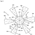
- the distributor arms 300 of the main distributor 44 which are designed in the form of a sector of a circle, can be of the type of Fig. 1 , which are separated from one another by said passage areas 45, for variably distributing the flow S of the liquid F in the radial direction R into a plurality of segments 351 to 353, each of which has at least one passage opening 370 through which the liquid F can rain on the tube bundle 20 underneath.
- a supply of liquid F into said segments 351 to 353 is now regulated separately for each of segments 351 to 353, for example by feeding each segment 351 to 353 via a downpipe that can be regulated by means of a valve (for example from a pre-distributor 43), the flow S of the liquid F in radial direction R of the jacket 80 or the tube bundle 20 can be variably distributed to a number of sections of the tube bundle 20 corresponding to the number of segments (see above).
- said control means 120 is correspondingly connected to said valves on the downpipe, so that they can be controlled in accordance with the instantaneous, in particular real-time, temperature distribution so that the actual temperature distribution approximates the target temperature distribution.
- the distributor arms 300 can be designed to apply liquid F to different sections of the tube bundle 20, for example by correspondingly distributing the through holes 371 of the distributor arms 300 along the radial direction R in accordance with Fig. 2 .
- the distributor arms 300 according to FIG Fig. 2 One through opening 371 each, which is displaced in the radial direction R with respect to the corresponding through openings 371 of the adjacent distributor arms 300.
- Other distributions of this type, in particular with a plurality of through holes per distributor arm 300, are also conceivable.
- the core tube 100 is divided into sections 381 to 386, so that a corresponding number of downpipes is formed, each of which is preferably designed to be controllable are (for example by means of valves) and in each case feed at least one assigned distributor arm 300 with the liquid F (cf. Fig. 2 ).
- a section 381 to 386 of the core tube 100 acts on the liquid F with more than one distributor arm 300, for example two distributor arms 300.
- Said down pipes 381 to 386 in turn can, for example, from a pre-distributor 43 according to Fig. 1 be fed.
- Said valves are in turn connected to the control means 120, so that the individual valves can be set as a function of the respective actual temperature distribution so that the currently measured actual temperature distribution approximates the predetermined target temperature distribution of the tube bundle 20.
- the tubes 20a are preferably coaxial with the jacket 80 of the heat exchanger 2 arranged tube bundle 20 is wound around the core tube 100 such that a plurality of sections R1, R2, R3 of the tube bundle 20 are formed, which are formed separately from one another and each encircle the core tube 100, the sections R1, R2, R3 embracing each other, but also each other can penetrate.
- the tubes 20a are preferably coaxial with the jacket 80 of the heat exchanger 2 arranged tube bundle 20 is wound around the core tube 100 such that a plurality of sections R1, R2, R3 of the tube bundle 20 are formed, which are formed separately from one another and each encircle the core tube 100, the sections R1, R2, R3 embracing each other, but also each other can penetrate.
- the tubes 20a are preferably coaxial with the jacket 80 of the heat exchanger 2 arranged tube bundle 20 is wound around the core tube 100 such that a plurality of sections R1, R2, R3 of the tube bundle 20 are formed, which are formed separately from one another and each encircle the core
- each section R1, R2, R3 can not only be supplied with the first medium separately via assigned inlets 51 to 56 at a lower end of the jacket 80 (in the present case, each section R1, R2, R3 has two inlets and without restriction of generality) Outlets; however, only one inlet or outlet can be provided per section), but the action on the pipe side can also be controlled via valves 71 to 76 assigned to inlets 51 to 56, which are correspondingly connected to control means 120 .
- the individual valves 71 to 76 are set by the control means 120 in such a way that the respective actual temperature distribution of the tube bundle 20 is adjusted to a desired target temperature distribution.
- the medium F 'introduced into the individual radial sections R1, R2, R3 can finally be withdrawn from the tube bundle 20 at an upper end of the jacket 80 via corresponding outlets 61 to 66 of the sections R1, R2, R3.
Landscapes
- Engineering & Computer Science (AREA)
- Physics & Mathematics (AREA)
- Thermal Sciences (AREA)
- Mechanical Engineering (AREA)
- General Engineering & Computer Science (AREA)
- General Physics & Mathematics (AREA)
- Heat-Exchange Devices With Radiators And Conduit Assemblies (AREA)
- Physical Or Chemical Processes And Apparatus (AREA)
- Measuring Temperature Or Quantity Of Heat (AREA)
- Control Of Temperature (AREA)
Description
Die Erfindung betrifft ein Verfahren zum Regeln einer Temperaturverteilung in einem gewickelten Wärmeübertrager.The invention relates to a method for regulating a temperature distribution in a wound heat exchanger.
Derartige gewickelte Wärmeübertrager sind aus dem Stand der Technik bekannt und dienen zum indirekten Wärmetausch zwischen zumindest zwei fluiden Medien.Such wound heat exchangers are known from the prior art and are used for indirect heat exchange between at least two fluid media.
Dabei sind bei einem gewickelten Wärmeübertrager eine Mehrzahl an Rohren, die ein Rohrbündel bilden, helikal um ein Kernrohr gewickelt, wobei jenes Rohrbündel von einem drucktragenden Mantel umschlossen ist, der einen das Rohrbündel umgebenden Mantelraum zur Aufnahme des einen Mediums definiert, wobei das andere Medium in dem besagten Rohrbündel geführt wird, so dass die beiden Medien in den besagten direkten Wärmeaustausch treten können. Das Kernrohr erstreckt sich dabei insbesondere entlang einer Längsachse, die - bezogen auf einen bestimmungsgemäß angeordneten Zustands des Wärmeübertragers bzw. des Mantels - mit der Vertikalen zusammenfällt. Ein derartig gewickelter Wärmeübertrager ist zum Beispiel aus der
Es ist ein Anliegen, diese energieoptimiert betreiben zu können. So möchte man zum Beispiel bei einem gewickelten Wärmeübertrager im Mantelraum eine möglichst gleichmäßige Verteilung der flüssigen Phase bzw. des Mediums auf das besagte Rohrbündel erreichen, um den Wärmeübertrager möglichst effizient betreiben zu können.It is important to be able to operate them in an energy-optimized manner. For example, in the case of a wound heat exchanger in the jacket space, one would like to achieve the most uniform possible distribution of the liquid phase or the medium over the said tube bundle in order to operate the heat exchanger as efficiently as possible.
Weiterhin beschreibt die
Entsprechend liegt der vorliegenden Erfindung das Problem zu Grunde, ein Verfahren zur Temperaturregelung in einem gewickelten Wärmeübertrager anzugeben, das einen energieoptimierten Betrieb ermöglicht.Accordingly, the present invention is based on the problem of specifying a method for temperature control in a wound heat exchanger, which enables energy-optimized operation.
Dieses Problem wird durch ein Verfahren zum Regeln einer Temperaturverteilung in einem Wärmeübertrager mit den Merkmalen des Anspruchs 1 gelöst.This problem is solved by a method for regulating a temperature distribution in a heat exchanger with the features of claim 1.
Danach wird bei dem erfindungsgemäßen Verfahren mittels zumindest eines in dem Wärmeübertrager angeordneten Lichtwellenleiters, insbesondere in Form einer Glasfaser oder einer sonstigen optischen Faser, eine Isttemperaturverteilung im Wärme-übertrager gemessen, wobei Licht in den mindestens einen Lichtwellenleiter eingestrahlt wird und in dem mindestens einen Lichtwellenleiter gestreutes Licht zur Ermittlung der Isttemperaturverteilung ausgewertet wird, und wobei zumindest ein im Wärmeübertrager geführter Strom eines fluiden Mediums so geregelt wird, dass die Isttemperaturverteilung einer vordefinierten Solltemperaturverteilung angenähert wird. Erfindungsgemäß ist dabei vorgesehen, dass der Wärmeübertrager ein Rohrbündel mit einer Vielzahl an Rohren aufweist, die in einem Mantelraum des Wärmeübertragers angeordnet sind, wobei die Isttemperaturverteilung mittels zumindest eines Lichtwellenleiters gemessen wird, der im Innenraum eines Rohres des Rohrbündels angeordnet ist und/oder mittels zumindest eines Lichtwellenleiters, der auf einer Außenseite eines Rohres des Rohrbündels im Mantelraum angeordnet ist, und wobei der Wärmeübertrager als ein gewickelter Wärmeübertrager ausgebildet ist, und wobei
- die Rohre eine Mehrzahl an separat mit jenem Medium beschickbare Sektionen des Rohrbündels bilden, wobei die einzelnen Sektionen jeweils so mit jenem Medium beschickt werden, dass die Isttemperaturverteilung der Solltemperaturverteilung angenähert wird,
oder - ein Strom eines flüssigen Mediums so im Mantelraum auf das Rohrbündel verteilt wird, dass die Isttemperaturverteilung der Solltemperaturverteilung angenähert wird, wobei das flüssige Medium in radialer Richtung des Rohrbündels und/oder in einer Umfangsrichtung des Rohrbündels variabel auf das Rohrbündel verteilt wird, so dass die Isttemperaturverteilung der Solltemperaturverteilung angenähert wird.
- the tubes form a plurality of sections of the tube bundle which can be fed separately with that medium, the individual sections being loaded with that medium in such a way that the actual temperature distribution approximates the target temperature distribution,
or - a flow of a liquid medium is distributed to the tube bundle in the jacket space such that the actual temperature distribution is approximated to the target temperature distribution, the liquid medium being in the radial direction of the tube bundle and / or in a circumferential direction of the tube bundle is variably distributed on the tube bundle, so that the actual temperature distribution approximates the target temperature distribution.
Zur Auswertung des gestreuten Lichts wird bevorzugt eine Messeinrichtung mit dem mindestens einem Lichtwellenleiter verbunden, die dazu eingerichtet und vorgesehen ist, mittels des besagten Lichtwellenleiters die Isttemperaturverteilung im Wärmeübertrager zu messen.To evaluate the scattered light, a measuring device is preferably connected to the at least one optical waveguide, which is set up and provided to measure the actual temperature distribution in the heat exchanger by means of said optical waveguide.
Die besagte Messeinrichtung ist hierzu bevorzugt dazu ausgebildet bzw. wird dazu verwendet, in den mindestens einen Lichtwellenleiter Licht bzw. optische Signale einzuleiten und in den Lichtleiter zurückgestreutes Licht in bekannter Weise auszuwerten. Hierbei wird ausgenutzt, dass die in dem Lichtwellenleiter eingesandten und zurückgestreuten optischen Signale stark temperaturabhängig und daher zur Temperaturmessung in der Umgebung des Lichtwellenleiters geeignet sind. Zur Auswertung solcher optischen Signale des Lichtleiters existieren mehrere Verfahrensweisen, die es erlauben, die Temperatur an einem beliebigen Punkt des Lichtleiters mit ausreichend hoher Präzision zu bestimmen.Said measuring device is preferably designed for this purpose or is used to introduce light or optical signals into the at least one optical waveguide and to evaluate light scattered back into the optical waveguide in a known manner. This takes advantage of the fact that the optical signals sent in and backscattered in the optical waveguide are highly temperature-dependent and are therefore suitable for temperature measurement in the vicinity of the optical waveguide. There are several procedures for evaluating such optical signals from the light guide, which allow the temperature at any point on the light guide to be determined with sufficient precision.
In einer bevorzugten Ausführungsform des erfindungsgemäßen Verfahrens ist die Messeinrichtung dazu eingerichtet und vorgesehen, durch den mindestens einen Lichtwellenleiter zurückgestreutes Licht auszuwerten, das durch Raman-Streuung des in den Lichtleiter eingeleiteten Lichtes entsteht. Hierbei wird ausgenutzt, dass Lichtwellenleiter in der Regel aus dotiertem Quarzglas (amorphe FestKörperstruktur, bestehend hauptsächlich aus Siliziumdioxid) gefertigt sind. In derartigen amorphen Festkörperstrukturen werden über thermische Effekte Gitterschwingungen induziert. Solche Gitterschwingungen sind temperaturabhängig. Licht, welches auf die Moleküle bzw. Partikel im Lichtleiter trifft, tritt daher in Wechselwirkung mit den Elektronen der Moleküle. Diese Wechselwirkung wird auch als Ramanstreuung bezeichnet. Das zurückgestreute Licht lässt sich in drei spektrale Gruppen einteilen. Neben der Rayleigh-Streuung, welche der Wellenlänge des eingestrahlten Lichts entspricht, existieren die sogenannte Stokes- und die sogenannten Anti-Stokes-Komponenten. Im Gegensatz zu den zu höheren Wellenlängen verschobenen und nur gering temperaturabhängigen Stokes-Komponenten sind die zu kleineren Wellenlängen verschoben Anti-Stokes-Komponenten deutlich temperaturabhängig. Die Messeinrichtung ist daher vorzugsweise dazu ausgebildet, das Intensitätsverhältnis zwischen Stokes- und Anti-Stokes-Komponenten zu berechnen, wobei die Messeinrichtung vorzugsweise dazu ausgebildet ist, hierzu eine Fourier-Transformation dieser beiden rückgestreuten Komponenten zu berechnen und mit einer Fourier-Transformation eines Referenzsignals zu vergleichen. Hieraus erhält man die Intensitäten der beiden Komponenten über der Länge des Lichtwellenleiters. Somit kann über den Vergleich der beiden Intensitäten die Temperatur für jeden Punkt des Lichtwellenleiters ermittelt werden.In a preferred embodiment of the method according to the invention, the measuring device is set up and provided for evaluating light backscattered by the at least one optical waveguide, which is produced by Raman scattering of the light introduced into the light guide. This takes advantage of the fact that optical waveguides are usually made of doped quartz glass (amorphous solid-body structure, consisting mainly of silicon dioxide). In such amorphous solid-state structures, lattice vibrations are induced via thermal effects. Such lattice vibrations are temperature-dependent. Light that strikes the molecules or particles in the light guide therefore interacts with the electrons of the molecules. This interaction is also known as Raman scattering. The backscattered light can be divided into three spectral groups. In addition to the Rayleigh scattering, which corresponds to the wavelength of the incident light, there are the so-called Stokes and the so-called Anti-Stokes components. In contrast to the Stokes components shifted to higher wavelengths and only slightly temperature-dependent, the anti-Stokes components shifted to smaller wavelengths are significantly temperature-dependent. The measuring device is therefore preferably designed to determine the intensity ratio to calculate between Stokes and Anti-Stokes components, the measuring device preferably being designed to calculate a Fourier transformation of these two backscattered components and to compare them with a Fourier transformation of a reference signal. The intensities of the two components over the length of the optical waveguide are obtained from this. The temperature for each point of the optical waveguide can thus be determined by comparing the two intensities.
Gemäß einer weiteren Variante des erfindungsgemäßen Verfahrens ist vorgesehen, dass die Temperaturbestimmung durch Auswertung der Rayleigh-Streuung erfolgt.According to a further variant of the method according to the invention, it is provided that the temperature is determined by evaluating the Rayleigh scatter.
Hierzu weist die Messeinrichtung bevorzugt ein kohärentes Frequenzbereichsreflektometer (auch als c-OFDR bezeichnet, für coherent Optical Frequency Domain Reflectometer) auf, bei dem Licht eines durchstimmbaren Lasers in ein Mach-Zehnder-Interferometer eingekoppelt wird, das das Licht auf zwei Strecken aufteilt, wobei der Lichtwellenleiter die eine Strecke bildet und die andere Strecke eine Referenzstrecke bekannte Länge ist. Das Rayleigh-Streulicht aus dem Lichtwellenleiter wird mit dem Lichtanteil aus der Referenzstrecke überlagert und detektiert. Beim Durchstimmen der Laserwellenlänge entsteht dabei am Detektor ein periodisches Signal, dessen Frequenz vom jeweiligen Streuort des Lichtwellenleiters abhängt. Die einzelnen Frequenzen dieses Signals, die über eine Fourier-Transformation erhältlich sind, entsprechen somit den Streuorten in dem Lichtwellenleiter; die Amplitude ihres Frequenzanteils gibt die Intensität der jeweiligen Reflexion an. Hierbei lassen sich Auflösungen ≤ 0,1 mm erzielen.For this purpose, the measuring device preferably has a coherent frequency range reflectometer (also referred to as c-OFDR, for coherent optical frequency domain reflectometer), in which light from a tunable laser is coupled into a Mach-Zehnder interferometer, which splits the light over two distances, whereby the optical waveguide forms one section and the other section is a reference section of known length. The Rayleigh scattered light from the optical waveguide is overlaid with the light component from the reference path and detected. When tuning the laser wavelength, a periodic signal is generated at the detector, the frequency of which depends on the scattering location of the optical waveguide. The individual frequencies of this signal, which can be obtained via a Fourier transformation, thus correspond to the scattering locations in the optical waveguide; the amplitude of their frequency component indicates the intensity of the respective reflection. Resolutions ≤ 0.1 mm can be achieved here.
Die Rayleigh-Strahlung in einem Lichtwellenleiter, wie zum Beispiel einer Glasfaser, entsteht durch elastische Streuprozesse an lokalen Effekten/Störungen des Lichtwellenleiters. Wird eine solche Glasfaser mittels c-OFDR abgetastet, ergibt sich ein für die Glasfaser charakteristischer, fluktuierender Intensitätsverlauf der Rayleigh-Streuung entlang der Glasfaser, der bei einer Temperaturänderung (Änderung der räumlichen Ausdehnung der Faser) räumlich gestreckt bzw. gestaucht wird, wodurch die Temperatur entlang der Glasfaser berechnet werden kann. Die Messeinrichtung ist entsprechend bevorzugt konfiguriert, das Signal entlang der Glasfaser in benachbarte Segmente (z.B. ≥ 1 mm) zu zerlegen und das entsprechende Signal in den Frequenzraum zu transformieren. Für jedes Segment ergibt sich dabei ein fluktuierendes Reflexionsmuster in Abhängigkeit von der Frequenz. Änderung der Temperatur bzw. Dehnung der Glasfaser bedingen eine Frequenzverschiebung, die insbesondere proportional zur Temperaturänderung der Glasfaser in jeweiligem Segment ist. Die Messeinrichtung ist entsprechend bevorzugt dazu ausgebildet, an Hand der jeweiligen Frequenzverschiebung die z,lokale) Temperatur der Glasfaser bzw. des Lichtwellenleiters zu ermitteln.The Rayleigh radiation in an optical waveguide, such as a glass fiber, arises from elastic scattering processes at local effects / disturbances of the optical waveguide. If such a glass fiber is scanned by means of c-OFDR, a characteristic, fluctuating intensity curve of the Rayleigh scattering along the glass fiber results, which is spatially stretched or compressed when there is a change in temperature (change in the spatial expansion of the fiber), which causes the temperature can be calculated along the fiber. The measuring device is accordingly preferably configured to split the signal along the glass fiber into adjacent segments (eg ≥ 1 mm) and to transform the corresponding signal into the frequency domain. For each segment there is a fluctuating reflection pattern depending on the frequency. Change of Temperature or expansion of the glass fiber cause a frequency shift, which is in particular proportional to the temperature change of the glass fiber in the respective segment. Accordingly, the measuring device is preferably designed to determine the z, local) temperature of the glass fiber or the optical waveguide using the respective frequency shift.
In einer weiteren Ausführungsform des erfindungsgemäßen Verfahrens erfolgt die Temperaturmessung über die Auswertung von optischen Signalen, wie sie durch Brillouin-Streuung des Lichtwellenleiters entstehen. In diesem Fall basiert die Temperaturmessung auf der ortsaufgelösten Bestimmung der Referenzfrequenz zwischen der in den Lichtwellenleiter eingeleiteten, primären Lichtwelle und der durch die in Folge von Brillouin-Streuung im Lichtleiter induzierten und zurückgestreuten Welle, welche in ihrer Frequenz in Abhängigkeit von der Temperatur gegenüber der Primärwelle verringert ist. Die Messeinrichtung ist daher vorzugsweise dazu ausgebildet, eine pulsförmige Primärlichtwelle in dem Lichtleiter einzuleiten und das rückgestreute Licht zeitaufgelöst für verschiedene Frequenzdifferenzen zu detektieren und unter Kenntnis der Pulslaufzeit die Frequenzverschiebung auf Grund der Temperaturveränderung ortsaufgelöst zu bestimmen. Auch in dieser Ausgestaltung der Erfindung lässt sich also durch die Auswertung der rückgestreuten optischen Signale die Temperatur an jedem beliebigen Punkt des Lichtwellenleiters bestimmen.In a further embodiment of the method according to the invention, the temperature measurement is carried out by evaluating optical signals such as those produced by Brillouin scattering of the optical waveguide. In this case, the temperature measurement is based on the spatially resolved determination of the reference frequency between the primary light wave introduced into the optical fiber and the wave induced and backscattered as a result of Brillouin scattering in the optical fiber, the frequency of which depends on the temperature compared to the primary wave is reduced. The measuring device is therefore preferably designed to introduce a pulse-shaped primary light wave into the light guide and to detect the backscattered light in a time-resolved manner for different frequency differences and to determine the frequency shift based on the temperature change based on the temperature change with knowledge of the pulse transit time. In this embodiment of the invention, too, the temperature at any point on the optical waveguide can be determined by evaluating the backscattered optical signals.
In einer weiteren Ausführungsform der Erfindung ist vorgesehen, die Temperatur über die Auswertung von optischen Signalen, wie sie durch Streuung am Bragg-Gitter entstehen, zu messen. Bragg-Gitter sind in den Lichtwellenleiter eingeschriebene, optische Bandfilter, welche nahezu beliebig oft im Lichtwellenleiter platziert werden können. Die Mittenwellenzahl des Bandstopps ergibt sich dabei aus der Bragg-Bedingung. Die spektrale Breite des Bandstopps hängt neben der Gitterlänger und der Brechzahl von der Temperatur ab. Die Messeinrichtung ist dann entsprechend dazu ausgebildet, bei gegebener und über den Lichtwellenleiter verschiedener Gitterlänge und Brechzahl die Temperatur an der jeweiligen Stelle des Bragg-Gitters über die Breite des Bandstopps zu bestimmen.In a further embodiment of the invention, it is provided to measure the temperature by evaluating optical signals as they arise from scattering on the Bragg grating. Bragg gratings are optical band filters inscribed in the optical fiber, which can be placed almost any number of times in the optical fiber. The center wave number of the band stop results from the Bragg condition. In addition to the grating length and the refractive index, the spectral width of the band stop depends on the temperature. The measuring device is then designed accordingly to determine the temperature at the respective point of the Bragg grating over the width of the band stop, given the grating length and refractive index using the optical waveguide.
Auf Grund der hohen Auflösung der erfindungsgemäßen Temperaturmessmethode kann die Isttemperaturverteilung bevorzugt als eine dreidimensionale Isttemperaturverteilung bzw. als ein dreidimensionales Isttemperaturprofil gemessen werden. Das heißt insbesondere, dass die Temperatur für eine Mehrzahl an dreidimensional im Raum verteilter Messorte genau angegeben werden kann. Hierzu wird der mindestens eine Lichtwellenleiter oder eine Mehrzahl an derartigen Lichtwellenleitern entlang der gewünschten Messorte verlegt, so dass sich der mindestens eine Lichtwellenleiter bzw. mehrere derartige Lichtwellenleiter von Messort zu Messort erstrecken. Die Messorte in dem Lichtwellenleiter liegen dabei sehr dicht beieinander, da die vorgenannten Auswertemethoden eine vergleichweise hohe räumliche Auflösung aufweisen.Due to the high resolution of the temperature measurement method according to the invention, the actual temperature distribution can preferably be measured as a three-dimensional actual temperature distribution or as a three-dimensional actual temperature profile become. In particular, this means that the temperature can be specified precisely for a plurality of three-dimensionally distributed measuring locations. For this purpose, the at least one optical waveguide or a plurality of such optical waveguides is laid along the desired measurement locations, so that the at least one optical waveguide or a plurality of such optical waveguides extend from measurement location to measurement location. The measuring locations in the optical waveguide are very close to one another, since the aforementioned evaluation methods have a comparatively high spatial resolution.
Nach dem erfindungsgemäßen Verfahren ist vorgesehen, dass der Wärmeübertrager ein Rohrbündel mit einer Vielzahl an Rohren aufweist, die in einem drucktragenden Mantelraum des Wärmeübertragers angeordnet sind, wobei bevorzugt die besagte Isttemperaturverteilung mittels zumindest eines Lichtwellenleiters bestimmt wird, der im Innenraum eines Rohres des Wärmeübertragers angeordnet ist oder mittels eines Lichtwellenleiters, der alternativ oder ergänzend auf einer Außenseite eines Rohres des Wärmeübertragers im Mantelraum des Wärmeübertragers angeordnet ist. Hierbei ist es natürlich möglich, jedes der Rohre des Rohrbündels des Wärmeübertragers mit einem in dem jeweiligen Rohr und/oder auf dem jeweiligen Rohr verlaufenden Lichtwellenleiter auszustatten, die dann bevorzugt zusammengeführt werden und in die vorstehend beschriebene Messeinrichtung eingekoppelt werden.According to the method according to the invention, it is provided that the heat exchanger has a tube bundle with a large number of tubes which are arranged in a pressure-bearing jacket space of the heat exchanger, the said actual temperature distribution preferably being determined by means of at least one optical waveguide which is arranged in the interior of a tube of the heat exchanger or by means of an optical waveguide, which is alternatively or additionally arranged on an outside of a tube of the heat exchanger in the jacket space of the heat exchanger. Here, it is of course possible to equip each of the tubes of the tube bundle of the heat exchanger with an optical waveguide running in the respective tube and / or on the respective tube, which are then preferably brought together and coupled into the measuring device described above.
Bevorzugt bilden die besagten Rohre des Rohrbündels des Wärmeübertragers eine Mehrzahl an separat mit dem besagten Medium beschickbare Sektionen des Rohrbündels aus, wobei die einzelnen Sektionen jeweils so mit einem Strom des Mediums schickt werden, das die Isttemperaturverteilung der Solltemperaturverteilung angenähert wird. Bei den besagten Sektionen handelt es sich bevorzugt um radiale Sektionen, d. h. die Rohre des Rohrbündels sind derart um das zugeordnete Kernrohr umwickelt, das zumindest eine das Kernrohr umlaufende erste Sektion des Rohrbündels und eine dazu separate, das Kernrohr umlaufende zweite Sektion des Rohrbündels gebildet wird, die die erste Sektion umgibt oder diese zumindest teilweise durchdringt, wobei die beiden Sektionen jeweils zumindest einen zugeordneten Einlass aufweisen, so dass die beiden Sektionen separat mit jenem Medium schickbar sind (sogenannte rohrseitige Regelung). Natürlich kann das Rohrbündel auf diese Weise in eine beliebige Mehrzahl an einzelnen, separat beschickbaren Sektionen aufgeteilt werden, die in radialer Richtung des Rohrbündels übereinanderliegen bzw. einander zumindest partiell durchdringen.Said tubes of the tube bundle of the heat exchanger preferably form a plurality of sections of the tube bundle that can be fed separately with the said medium, the individual sections being sent with a flow of the medium that approximates the actual temperature distribution to the target temperature distribution. Sections are preferably radial sections, ie the tubes of the tube bundle are wrapped around the assigned core tube in such a way that at least one first section of the tube bundle surrounding the core tube and a separate second portion of the tube bundle surrounding the core tube are formed, which surrounds the first section or at least partially penetrates it, the two sections each having at least one assigned inlet, so that the two sections can be sent separately with that medium (so-called pipe-side regulation). Of course, the tube bundle can be divided into any number of individual, separately feedable sections in this way are, which lie one above the other in the radial direction of the tube bundle or at least partially penetrate each other.
Mittels eines Regelmittels wird dann bevorzugt die Einspeisung des besagten Mediums über den Einlass der ersten Sektion separat von der Einspeisung des Mediums über den Einlass der zweiten Sektion geregelt. Hierbei umfasst das Regelmittel bevorzugt zumindest ein Ventil für den Einlass der ersten Sektion und ein Ventil für den Einlass der zweiten Sektion. Entsprechendes gilt bei einer beliebigen Mehrzahl von Sektionen des Rohrbündels. Weiterhin weisen die besagten Sektionen jeweils zumindest einen zugeordneten Auslass zum Auslassen des Mediums aus der jeweiligen Sektion des Rohrbündels auf.By means of a regulating means, the feed of said medium via the inlet of the first section is then preferably regulated separately from the feed of the medium via the inlet of the second section. The control means preferably comprises at least one valve for the inlet of the first section and one valve for the inlet of the second section. The same applies to any number of sections of the tube bundle. Furthermore, said sections each have at least one assigned outlet for discharging the medium from the respective section of the tube bundle.
Gemäß einer weiteren Variante des erfindungsgemäßen Verfahrens ist vorgesehen, dass bei einem Wärmeübertrager in Form eines gewickelten Wärmeübertragers ein Strom eines flüssigen Mediums so im Mantelraum auf das besagte Rohrbündel verteilt wird, dass die Isttemperaturverteilung der Solltemperaturverteilung angenähert wird (sogenannte mantelseitige Regelung).According to a further variant of the method according to the invention, it is provided that, in the case of a heat exchanger in the form of a wound heat exchanger, a stream of a liquid medium is distributed in the jacket space to the said tube bundle in such a way that the actual temperature distribution is approximated to the target temperature distribution (so-called jacket-side regulation).
Eine derartig variable Flüssigkeitsverteilung im Mantelraum wird bei dem erfindungsgemäßen Verfahren bevorzugt mit einem oberhalb des Rohrbündels angeordneten Flüssigkeitsverteiler zum Verteilen des besagten Stromes im Mantelraum durchgeführt. Hierbei ist bevorzugt ein Regelmittel vorgesehen, das dazu ausgebildet ist, die Verteilung des besagten Stromes der Flüssigkeit im Mantelraum zu regeln. Alternativ oder ergänzend kann das Regelmittel dazu eingerichtet und vorgesehen sein, die Verteilung eines zusätzlichen, im Mantelraum geführten weiteren Stromes der Flüssigkeit im Mantelraum zu regeln.Such a variable liquid distribution in the jacket space is preferably carried out in the method according to the invention with a liquid distributor arranged above the tube bundle for distributing said flow in the jacket space. In this case, a regulating means is preferably provided which is designed to regulate the distribution of said flow of liquid in the jacket space. Alternatively or additionally, the regulating means can be set up and provided to regulate the distribution of an additional, further flow of the liquid carried in the jacket space in the jacket room.
Hierbei wird bevorzugt der besagte Strom und/oder jene weitere Strom des flüssigen Mediums in einer radialen Richtung des Mantels bzw. des Rohrbündels zumindest auf eine erste und eine zweite Sektion des Rohrbündels und/oder in einer Umfangsrichtung des Mantels bzw. Rohrbündels variabel verteilt, so dass die gemessenen Isttemperaturverteilungen entsprechend einer vorgegebenen Solltemperaturverteilung angeglichen werden.In this case, the said flow and / or that further flow of the liquid medium in a radial direction of the jacket or the tube bundle is preferably variably distributed at least to a first and a second section of the tube bundle and / or in a circumferential direction of the jacket or tube bundle, so that the measured actual temperature distributions are adjusted according to a predetermined target temperature distribution.
Hierbei kann zum Beispiel ein radial weiter außen gelegener Bereich bzw. Sektion des Rohrbündels innerhalb einer bestimmten Zeitspanne mehr Flüssigkeit erhalten als ein weiter innenliegender Bereich bzw. Sektion. In gleicher Weise kann entlang der Umfangsrichtung variabel Flüssigkeit auf das Rohrbündel aufgegeben werden.Here, for example, a region or section of the tube bundle located radially further outside can receive more liquid within a certain period of time than a region or section located further inside. In the same way, liquid can be applied variably to the tube bundle along the circumferential direction.
Das erfindungsgemäße Verfahren wird vorzugsweise mit einer Einrichtung durchgeführt, die einen gewickelten Wärmeübertrager aufweist, sowie zumindest einen im Wärmeübertrager angeordneten Lichtwellenleiter zum Messen einer insbesondere dreidimensionalen Isttemperaturverteilung des Wärmeübertragers, und eine mit dem mindestens einem Lichtwellenleiter verbundene Messeinrichtung, die dazu eingerichtet und vorgesehen ist, Licht in den mindestens einen Lichtwellenleiter einzukoppeln und in dem mindestens einen Lichtwellenleiter gestreutes Licht zur Ermittlung der Isttemperaturverteilung auszuwerten, wobei die Einrichtung des Weiteren ein Regelmittel zum Regeln zumindest eines im Wärmeübertrager geführten Stromes aufweist, derart, dass die Isttemperaturverteilung einer vordefinierten SollTemperaturverteilung angenähert wird.The method according to the invention is preferably carried out with a device which has a wound heat exchanger, and at least one optical waveguide arranged in the heat exchanger for measuring an in particular three-dimensional actual temperature distribution of the heat exchanger, and a measuring device connected to the at least one optical waveguide, which is set up and provided for this purpose To couple into the at least one optical waveguide and to evaluate light scattered in the at least one optical waveguide in order to determine the actual temperature distribution, the device further comprising regulating means for regulating at least one current carried in the heat exchanger in such a way that the actual temperature distribution is approximated to a predefined target temperature distribution.
Weiterhin weist der gewickelte Wärmeübertrager ein gewickeltes Rohrbündel mit einer Vielzahl an Rohren auf, die in einem Mantelraum des Wärmeübertragers in mehreren Lagen um ein Kernrohr gewickelt sind, wobei der mindestens eine Lichtwellenleiter im Innenraum eines Rohres des gewickelten Rohrbündels des Wärmeübertragers oder auf einer Außenseite des Rohres des gewickelten Rohrbündels des Wärmeübertragers im Mantelraum angeordnet ist. Hierbei kann wiederum jedes Rohr des Wärmeübertragers mit einem im Rohr und/oder einem außen auf dem Rohr verlaufenden Lichtwellenleiter ausgestattet sein, wobei jene Lichtwellenleiter dann zusammengeführt werden und mit der Messeinrichtung gekoppelt werden.Furthermore, the wound heat exchanger has a wound tube bundle with a plurality of tubes which are wound in several layers around a core tube in a jacket space of the heat exchanger, the at least one optical waveguide in the interior of a tube of the wound tube bundle of the heat exchanger or on an outside of the tube of the wound tube bundle of the heat exchanger is arranged in the jacket space. Here, in turn, each tube of the heat exchanger can be equipped with an optical waveguide running in the tube and / or on the outside of the tube, those optical waveguides then being brought together and coupled to the measuring device.
Die besagten Rohre des Wärmeübertragers bilden bevorzugt eine Mehrzahl an separat mit jenem Medium beschickbaren Sektionen des Rohrbündels aus, wobei diese einzelnen Sektionen jeweils so mit dem besagten Strom des Mediums beschickt werden, dass die gemessene Isttemperaturverteilung der gewünschten Solltemperaturverteilung angenähert wird (sogenannte rohrseitige Regelung).Said tubes of the heat exchanger preferably form a plurality of sections of the tube bundle that can be fed separately with that medium, whereby these individual sections are each loaded with the said flow of the medium in such a way that the measured actual temperature distribution is approximated to the desired target temperature distribution (so-called pipe-side regulation).
Bei dem gewickelten Wärmeübertrager sind dabei die Rohre des Rohrbündels bevorzugt derart um das Kernrohr des gewickelten Wärmeübertragers gewickelt, dass zumindest eine das Kernrohr umlaufende erste Sektion des Rohrbündels und eine dazu separate, das Kernrohr umlaufende zweite Sektion des Rohrbündels gebildet wird, die die erste Sektion umgibt, oder diese zumindest teilweise durchdringt, wobei die beiden Sektionen jeweils zumindest einen zugeordneten Einlass aufweisen, so dass die beiden Sektionen separat mit jenem Medium beschickbar sind. Hierbei kann natürlich wiederum eine beliebige Mehrzahl derartiger Sektionen vorgesehen sein.In the case of the wound heat exchanger, the tubes of the tube bundle are preferably wound around the core tube of the wound heat exchanger in such a way that at least one first section of the tube bundle encircling the core tube and a separate second section of the tube bundle encircling the core tube, which surrounds or at least partially penetrates the first section, is formed, the two sections each having at least one assigned inlet, so that the both sections can be loaded separately with that medium. Any number of such sections can of course be provided here.
Das Regelmittel ist dann diesbezüglich bevorzugt dazu ausgebildet, die Einspeisung des Mediums über den Einlass der ersten Sektion separat von der Einspeisung des Mediums über den Einlass der zweiten Sektion zu regeln. Entsprechendes gilt bei einer beliebigen Mehrzahl an Sektionen. Hierzu umfasst das Regelmittel zumindest ein Ventil für den Einlass der ersten Sektion und ein Ventil für den Einlass der zweiten Sektion. Entsprechendes gilt bei einer Mehrzahl an Sektionen. Des Weiteren weisen die einzelnen Sektionen jeweils zumindest einen zugeordneten Auslass zum Auslassen des ersten Mediums aus der jeweiligen Sektion des Rohrbündels auf.In this regard, the regulating means is preferably designed to regulate the feed of the medium via the inlet of the first section separately from the feed of the medium via the inlet of the second section. The same applies to any number of sections. For this purpose, the control means comprises at least one valve for the inlet of the first section and one valve for the inlet of the second section. The same applies to a plurality of sections. Furthermore, the individual sections each have at least one assigned outlet for discharging the first medium from the respective section of the tube bundle.
Alternativ oder ergänzend zu einer rohrseitigen Regelung kann bei einem Wärmeübertrager in Form eines gewickelten Wärmeübertragers auch eine mantelseitige Regelung vorgesehen werden.As an alternative or in addition to a pipe-side control, a jacket-side control can also be provided in the case of a heat exchanger in the form of a wound heat exchanger.
Hierbei ist die Einrichtung bevorzugt dazu ausgebildet, einen Strom eines flüssigen Mediums so im Mantelraum variabel auf das Rohrbündel zu verteilen, dass die Isttemperaturverteilung der Solltemperaturverteilung angenähert wird. Eine solche Regelung kann wie bereits eingangs dargelegt über einen Flüssigkeitsverteiler oder eine zusätzliche Einleitung von Strömen in den Mantelraum geregelt werden. Eine Variante der Einrichtung sieht diesbezüglich einen Flüssigkeitsverteiler zum Verteilen des besagten Stromes im Mantelraum vor, der insbesondere oberhalb des Rohrbündels im Mantelraum angeordnet ist. Dabei ist das Regelmittel insbesondere dazu ausgebildet, die Verteilung des besagten Stromes im Mantelraum zu regeln und/oder die Verteilung eines zusätzlichen in dem Mantelraum geführten, weiteren Stromes des flüssigen Mediums im Mantelraum zu regeln. Hierbei kann der Flüssigkeitsverteiler einen Hauptverteiler oberhalb des Rohrbündels zur Aufnahme des zur verteilenden flüssigen Mediums des besagten Stromes aufweisen, wobei der Hauptverteiler bevorzugt Durchgangsöffnungen aufweist, durch die hindurch das Medium auf das Rohrbündel aufgebbar ist.Here, the device is preferably designed to variably distribute a flow of a liquid medium in the jacket space over the tube bundle in such a way that the actual temperature distribution is approximated to the target temperature distribution. Such a regulation can, as already explained at the beginning, be regulated via a liquid distributor or an additional introduction of flows into the jacket space. In this regard, a variant of the device provides a liquid distributor for distributing said flow in the jacket space, which is arranged in particular above the tube bundle in the jacket space. The control means is in particular designed to regulate the distribution of said flow in the jacket space and / or to regulate the distribution of an additional, further flow of the liquid medium in the jacket space in the jacket space. Here, the liquid distributor can have a main distributor above the tube bundle for receiving the liquid medium to be distributed of the said stream, the main distributor preferably having through-openings through which the medium can be applied to the tube bundle.
In einer Variante der Einrichtung ist zumindest eine zusätzliche Leitung mit zumindest einem Auslass vorgesehen, über den der weitere Strom der Flüssigkeit regelbar auf das Rohrbündel aufgebbar ist, wobei das Regelmittel insbesondere zum Regeln der Verteilung des weiteren Stromes der Flüssigkeit zumindest ein Ventil für die besagte Leitung aufweist. In diesem Zusammenhang kann der Hauptverteiler zumindest einen Durchgangsbereich aufweisen, durch den Rohre des Rohrbündels hindurchgeführt sind, wobei jener Durchgangsbereich insbesondere durch zwei Verteilerarme des Hauptverteilers begrenzt sein kann, über die die Flüssigkeit bzw. das Medium auf das Rohrbündel aufgebbar ist.In a variant of the device, at least one additional line with at least one outlet is provided, via which the further flow of the liquid can be regulatedly applied to the tube bundle, the control means, in particular for regulating the distribution of the further flow of the liquid, at least one valve for the said line having. In this context, the main distributor can have at least one passage area through which tubes of the tube bundle are passed, whereby this passage region can be limited in particular by two distributor arms of the main distributor, via which the liquid or the medium can be applied to the tube bundle.
Hierbei kann die besagte mindestens eine Leitung durch die mindestens einen Durchgangsbereich hindurchgeführt sein. Somit kann eine Verteilung über den Hauptverteiler als auch über die zusätzlichen Leitungen vorgenommen werden. Bevorzugt sind dabei eine Mehrzahl an derartigen Leitungen mit je zumindest einem Auslass vorgesehen, über die der weitere Strom der Flüssigkeit regelbar auf das Rohrbündel aufgebbar ist, wobei die Auslässe so über den Querschnitt des Mantelraums verteilt sind, dass der weitere Strom der Flüssigkeit in einer radialen Richtung des Mantels zumindest auf eine erste und eine zweite Sektion des Rohrbündels (bzw. auf eine beliebige Mehrzahl an Sektionen) und/oder einer Umfangsrichtung des Mantels variabel verteilbar ist, um insbesondere die wiederholt gemessene Isttemperaturverteilung einer vordefinierten Solltemperaturverteilung anzupassen.In this case, said at least one line can be led through the at least one passage area. Distribution can thus be carried out via the main distributor and also via the additional lines. A plurality of such lines, each with at least one outlet, are preferably provided, via which the further flow of the liquid can be regulatedly applied to the tube bundle, the outlets being distributed over the cross section of the jacket space such that the further flow of the liquid is in a radial direction The direction of the jacket can be variably distributed to at least a first and a second section of the tube bundle (or to any number of sections) and / or a circumferential direction of the jacket, in order in particular to adapt the repeatedly measured actual temperature distribution to a predefined target temperature distribution.
In einer Variante der Einrichtung ist vorgesehen, dass der Hauptverteiler des Flüssigkeitsverteilers eine Mehrzahl an Verteilerarmen aufweist, die insbesondere jeweils in radialer Richtung des Mantels bzw. des Kernrohres oder auch Rohrbündels erstreckt sind.In a variant of the device, it is provided that the main distributor of the liquid distributor has a plurality of distributor arms, which in particular each extend in the radial direction of the jacket or the core tube or also the tube bundle.
Dabei ist weiterhin bevorzugt vorgesehen, dass die Verteilerarme zum variablen Verteilen des Stromes der Flüssigkeit in radialer Richtung zumindest in zwei separate Segmente unterteilt sind, die jeweils zumindest eine Durchgangsöffnung aufweisen, durch die hindurch Flüssigkeit auf das Rohrbündel aufgebbar ist, wobei das Regelmittel bevorzugt dazu eingerichtet und vorgesehen ist, eine Zufuhr von Flüssigketi in die beiden Segmente separat zu regeln, so dass die Flüssigkeit in radialer Richtung des Mantels auf zumindest eine erste und eine zweite Sektion des Rohrbündels entsprechend variabel verteilbar ist. Entsprechendes gilt bei einer beliebigen Mehrzahl an Sektionen.It is further preferably provided that the distributor arms for variably distributing the flow of the liquid in the radial direction are divided into at least two separate segments, each of which has at least one through-opening through which liquid can be applied to the tube bundle, the control means preferably being set up for this and it is provided to separately regulate a supply of liquid ketone into the two segments, so that the liquid in the radial direction of the Jacket can be variably distributed on at least a first and a second section of the tube bundle. The same applies to any number of sections.
Weiterhin kann vorgesehen sein, dass zumindest ein Verteilerarm dazu eingerichtet und vorgesehen ist, entlang der radialen Richtung des Mantels eine erste Sektion mit Flüssigkeit zu beaufschlagen, und dass zumindest ein anderer Verteilerarm dazu eingerichtet vorgesehen ist, entlang der radialen Richtung des Mantels eine davon verschiedene zweite Sektion des Rohrbündels mit Flüssigkeit zu beaufschlagen, wobei insbesondere die beiden Verteilerarme zum Verteilen der Flüssigkeit auf die beiden Sektionen je zumindest eine Durchgangsöffnung aufweisen, durch die hindurch Flüssigkeit auf das Rohrbündel aufgebbar ist, wobei jene Durchgangsöffnungen entlang der radialen Richtung unterschiedlich positioniert sind, und wobei insbesondere zum Speisen der einzelnen Verteilerarme mit der Flüssigkeit eine Mehrzahl an Fallrohren vorgesehen ist, wobei ein Fallrohr je zumindest einen, insbesondere zwei Verteilerarme mit Flüssigkeit beaufschlagt, und wobei insbesondere die Fallrohre im Kernrohr angeordnet sind oder durch eine Unterteilung des Kernrohres in Sektionen gebildet sind.Furthermore, it can be provided that at least one distributor arm is set up and provided to apply liquid to a first section along the radial direction of the shell, and that at least one other distributor arm is set up to set up a different second one along the radial direction of the shell To apply section of the tube bundle with liquid, in particular the two distributor arms for distributing the liquid to the two sections each have at least one through opening through which liquid can be applied to the tube bundle, those through openings being positioned differently along the radial direction, and wherein In particular for supplying the individual distributor arms with the liquid, a plurality of downpipes is provided, with a downpipe acting on at least one, in particular two, distributor arms with liquid, and in particular the downpipes being arranged in the core tube are or are formed by dividing the core tube into sections.
Andere Vorrichtungen, zur radial variablen bzw. variablen Verteilung in Umfangsrichtung des Rohrbündels können auch vorgesehen werden.Other devices for radially variable or variable distribution in the circumferential direction of the tube bundle can also be provided.
Weitere Einzelheiten und Vorteile der Erfindung sollen durch die nachfolgende Figurenbeschreibungen von Ausführungsbeispielen an Hand der Figuren erläutert werden.Further details and advantages of the invention are to be explained by the following description of figures of exemplary embodiments with reference to the figures.
Es zeigen:
- Fig. 1
- eine schematische Schnittansicht eines gewickelten Wärmeübertragers mit rohr- und/oder mantelseitiger Regelung in Abhängigkeit einer gemessenen Isttemperaturverteilung des Wärmeübertragers;
- Fig. 2
- eine Draufsicht auf einen Flüssigkeitsverteiler zur mantelseitigen Regelung in Abhängigkeit einer gemessenen Isttemperaturverteilung; und
- Fig. 1
- a schematic sectional view of a wound heat exchanger with pipe and / or jacket-side control in dependence on a measured actual temperature distribution of the heat exchanger;
- Fig. 2
- a plan view of a liquid distributor for jacket-side control as a function of a measured actual temperature distribution; and
In dem durch das Rohrbündel 20 gebildeten Rohrraum wird zumindest ein erstes Medium F' eingespeist, das entlang der Vertikalen Z aufwärts strömt. Der Mantelraum M dient zur Aufnahme eines zweiten Mediums in Form einer Flüssigkeit F, die auf das mindestens eine Rohrbündel 20 aufgegeben wird und im Mantelraum M entlang der Vertikalen Z abwärts strömt. Aufgrund der Ausbildung des Rohrbündels 20 als gewickeltes Rohrbündel 20 wird das erste Medium F' somit im Kreuzgegenstrom zur Flüssigkeit F geführt.At least a first medium F ′, which flows upwards along the vertical Z, is fed into the tube space formed by the
Zum dreidimensionalen Messen einer Isttemperaturverteilung im Mantelraum M bzw. im Rohrbündel 20 ist zumindest ein Lichtwellenleiter 101 vorgesehen, der sich zum Beispiel in einem der Rohre 20a helikal - dem Verlauf des Rohres 20a entsprechend - erstreckt oder außerhalb eines solchen Rohres 20a angeordnet ist, um die Temperatur im Wärmeübertrager 2 dreidimensional zu vermessen. Es können natürlich eine Vielzahl an derartigen Lichtwellenleitern 101 in den einzelnen Rohren 20a oder auf den einzelnen Rohren 20a oder in sonstiger Weise im Mantelraum M angeordnet sein, um spezifische Bereiche des Wärmeübertragers 2 vermessen zu können. Der mindestens eine Lichtwellenleiter 101 wird vorzugsweise aus dem Mantelraum M herausgeführt und mit einer Messeinrichtung 110 gekoppelt, die dazu ausgebildet ist, in dem Lichtwellenleiter 101 zurückgestreutes Licht zur Bestimmung der Temperatur im Wärmeübertrager 2 auszuwerten. Da auf Grund dieser Messmethode eine Vielzahl an Messpunkten entlang des Lichtwellenleiters 101 erhalten werden, kann bei einer dreidimensionalen Anordnung des mindestens einen Lichtwellenleiters 101 eine dreidimensionale Isttemperaturverteilung in Echtzeit gemessen werden. Um einen optimalen Betrieb des Wärmeübertragers 2 gewährleisten zu können, wird eine entsprechende Solltemperaturverteilung des Rohrbündels 20 festgelegt, die einem solchen optimierten Betrieb entspricht. So kann zum Beispiel durch eine laufende Messung der Isttemperaturverteilung (auch als Isttemperaturprofil bezeichnet) des Rohrbündels 20 eine Ungleichverteilung des zweiten Mediums bzw. der flüssigen Phase F auf das Rohrbündel 20 detektiert werden, da diese eine entsprechende Isttemperaturverteilung des Rohrbündels 20 zur Folge hat. Um derartige Fehlverteilungen korrigieren zu können, ist die besagte Messeinrichtung 110 mit einem Regelmittel 120 gekoppelt, dass dazu ausgebildet ist, rohrseitig oder mantelseitig geführte Medien F, F' bzw. Ströme S, S' so einzuregeln, dass die jeweils gemessene Isttemperaturverteilung der gewünschten Solltemperaturverteilung angenähert wird.For three-dimensional measurement of an actual temperature distribution in the jacket space M or in the
Zum Verteilen der Flüssigkeit F im Mantelraum M wird beispielsweise ein in den Mantel 80 eingeleiteter Strom S der Flüssigkeit F in einem Vorverteiler 43 gesammelt, beruhigt und entgast. Der Vorverteiler 43 weist zum Aufnehmen der Flüssigkeit F dabei eine umlaufende Wandung auf, die von einem quer zur Längsachse Z des Mantels 20 verlaufenden Boden abgeht. Der Boden des Vorteilers 43 ist über ein im Kernrohr 100 verlaufendes Fallrohr 380 mit einem Hauptverteiler 44 des Flüssigkeitsverteilers 40 verbunden, um diesen mit dem Strom S der Flüssigkeit F zu speisen, wobei jener Hauptverteiler 44 zum Verteilen des Stromes S der Flüssigkeit F über den gesamten Querschnitt des Mantelraums M quer zur Vertikalen Z eine Mehrzahl an Verteilerarmen 300 aufweist (vgl.
Die Verteilerarme 300 weisen jeweils einen Boden mit einer Mehrzahl an Durchgangsöffnungen auf, sogenannte Lochböden, durch die hindurch in die Verteilerarme 300 eingeleitete Flüssigkeit F auf das entlang der Vertikalen Z darunter angeordnete Rohrbündel 20 regnen kann.The
Um nun auf die Verteilung der Flüssigkeit F im Mantelraum M Einfluss nehmen zu können und gegebenenfalls zum Beispiel einer Ungleichverteilung entgegenwirken zu können, wird nun mantelseitig die Verteilung und Zuführung eines Teils der Flüssigkeit F in Form zumindest eines weiteren Stromes S' parallel zum (Haupt)Strom S geführt.In order to be able to influence the distribution of the liquid F in the jacket space M and, if necessary, to counteract an uneven distribution, for example can, the distribution and supply of part of the liquid F in the form of at least one further stream S 'is now carried out parallel to the (main) stream S on the jacket side.
Hierzu sind zusätzliche Leitungen 481 bis 484 zum Leiten des weiteren Stromes S' (bzw. der weiteren Ströme) vorgesehen, die über entsprechende Einlässe/Stutzen 281 bis 284 in den Mantelraum M geführt sind, und jeweils zumindest einen Auslass 485 aufweisen, über den die Flüssigkeit F zusätzlich regelbar auf das mindestens eine Rohrbündel 20 aufgegeben werden kann. Hierzu verfügen die besagten Leitungen 481 bis 484 jeweils über ein zugeordnetes Ventil 181 bis 184, das mittels des Regelmittels 120 regelbar ist, so dass das Regelmittel 120 entsprechend der momentanen Isttemperaturverteilung die einzelnen Ventile 181 bis 184 so stellen kann, dass der zusätzliche Strom S' der Flüssigkeit F derart auf das Rohrbündel 20 verteilt wird, dass sich die laufend gemessene Isttemperaturverteilung an die vorgegebene Solltemperaturverteilung annähert. Um die Flüssigkeit F dabei kontrolliert über die Leitungen 481 bis 484 auf das Rohrbündel 20 aufgeben zu können, sind die Leitungen 481 bis 484 durch die besagten Durchgangsbereiche 45 des Hauptverteilers 44 hindurchgeführt, wobei die Auslässe 485 der Leitungen 481 bis 484 oberhalb des Rohrbündels 20 angeordnet sind, und zwar insbesondere so, dass das Rohrbündel 20 in der radialen Richtung R des Mantels 80 bzw. des Rohrbündels 20 sektionsweise separat regelbar mit der Flüssigkeit F beaufschlagbar ist. Die einzelnen Sektionen können jeweils radial weiter innen gelegene Sektionen umgreifen, wobei sich benachbarte Sektionen auch gegenseitig durchdringen können.For this purpose,
Neben der mantelseitigen Regelung eines zusätzlichen Stromes S' besteht auch die Möglichkeit, den Hauptstrom S über den Flüssigkeitsverteiler 40 selbst zu regeln. Dies ist in
Alternativ hierzu können die Verteilerarme 300 dazu ausgebildet sein, unterschiedliche Sektionen des Rohrbündels 20 mit Flüssigkeit F zu beaufschlagen, zum Beispiel durch eine entsprechende Verteilung der Durchgangslöcher 371 der Verteilerarme 300 entlang der radialen Richtung R gemäß
Um nun die einzelnen Verteilerarme 300 mit Flüssigkeit F des (Haupt)Stromes S beschicken zu können, ist vorzugsweise vorgesehen, dass das Kernrohr 100 in Sektionen 381 bis 386 unterteilt ist, so dass eine entsprechende Anzahl an Fallrohren gebildet wird, die jeweils vorzugsweise regelbar ausgestaltet sind (zum Beispiel mittels Ventilen) und jeweils zumindest einem zugeordneten Verteilerarm 300 mit der Flüssigkeit F beschicken (vgl.
Alternativ oder ergänzend zur vorgenannten mantelseitigen Regelung von Medienströmen S bzw. S' besteht gemäß
Claims (2)
- Method for controlling a temperature distribution in a heat exchanger, with which an actual temperature distribution in the heat exchanger (2) is measured by means of at least one optical waveguide (101), especially in the form of a glass fiber, arranged in the heat exchanger (2), wherein light is coupled into the at least one optical waveguide (101) and light dispersed in the optical waveguide (101) is analyzed to determine the actual temperature distribution, and wherein the heat exchanger (2) has a tube bundle (20) having a plurality of tubes (20a) arranged in a shell space (M) of the heat exchanger (2), and wherein the actual temperature distribution is measured by means of the at least one optical waveguide (101), which is arranged in the interior of a tube (20a) of the tube bundle (20) and/or on an exterior of a tube (20a) of the tube bundle (20) in the shell space (M), and wherein the heat exchanger (2) is configured as a coil-wound heat exchanger,
characterized in that
at least one stream (S, S') of a fluid medium (F, F') conducted in the heat exchanger (2) is controlled such that the actual temperature distribution is approximated to a target temperature distribution, and wherein- the tubes (20a) form a plurality of sections (R1, R2, R3) of the tube bundle (20) which can be separately filled with said medium, wherein the individual sections (R1, R2, R3) are each filled with said medium (F') in such a way that the actual temperature distribution is approximated to the target temperature distribution,
or- a stream (S, S') of a fluid medium (F) is distributed in the shell space (M) into the tube bundle (20) in such a way that the actual temperature distribution is approximated to the target temperature distribution, wherein the fluid medium (F) is variably distributed into the tube bundle (20) in the radial direction (R) of the tube bundle (20) and/or in a circumferential direction (U) of the tube bundle (20) so that the actual temperature distribution is approximated to the target temperature distribution. - Method according to claim 1, characterized in that a three-dimensional actual temperature distribution is measured as the actual temperature distribution.
Priority Applications (1)
| Application Number | Priority Date | Filing Date | Title |
|---|---|---|---|
| EP13774072.6A EP2906897B1 (en) | 2012-10-09 | 2013-10-02 | Method for controlling a temperature distribution in a heat exchanger |
Applications Claiming Priority (3)
| Application Number | Priority Date | Filing Date | Title |
|---|---|---|---|
| EP12006983 | 2012-10-09 | ||
| PCT/EP2013/002976 WO2014056588A1 (en) | 2012-10-09 | 2013-10-02 | Method for controlling a temperature distribution in a heat exchanger |
| EP13774072.6A EP2906897B1 (en) | 2012-10-09 | 2013-10-02 | Method for controlling a temperature distribution in a heat exchanger |
Publications (2)
| Publication Number | Publication Date |
|---|---|
| EP2906897A1 EP2906897A1 (en) | 2015-08-19 |
| EP2906897B1 true EP2906897B1 (en) | 2020-07-08 |
Family
ID=47088616
Family Applications (1)
| Application Number | Title | Priority Date | Filing Date |
|---|---|---|---|
| EP13774072.6A Active EP2906897B1 (en) | 2012-10-09 | 2013-10-02 | Method for controlling a temperature distribution in a heat exchanger |
Country Status (7)
| Country | Link |
|---|---|
| US (1) | US9766024B2 (en) |
| EP (1) | EP2906897B1 (en) |
| CN (1) | CN104884893B (en) |
| AU (1) | AU2013329887B2 (en) |
| MY (1) | MY182637A (en) |
| RU (1) | RU2656223C2 (en) |
| WO (1) | WO2014056588A1 (en) |
Families Citing this family (14)
| Publication number | Priority date | Publication date | Assignee | Title |
|---|---|---|---|---|
| US9745069B2 (en) * | 2013-01-21 | 2017-08-29 | Hamilton Sundstrand Corporation | Air-liquid heat exchanger assembly having a bypass valve |
| EP3006875A1 (en) * | 2014-10-09 | 2016-04-13 | Linde Aktiengesellschaft | Method for regulating a coupled heat exchanger system and heat exchanger system |
| DE102014018825A1 (en) | 2014-12-19 | 2016-06-23 | Man Diesel & Turbo Se | Fiber optic temperature measurement |
| WO2016188635A1 (en) * | 2015-05-28 | 2016-12-01 | Linde Aktiengesellschaft | Method for determining the state of a heat exchanger device |
| EP3128278B1 (en) * | 2015-08-06 | 2018-06-20 | Linde Aktiengesellschaft | Feeding and removal of pipe streams with interim temperature in coiled heat exchangers |
| DE102016000246A1 (en) * | 2016-01-12 | 2017-07-13 | Linde Aktiengesellschaft | Method for determining a strain load change of a plate heat exchanger |
| WO2017157533A1 (en) * | 2016-03-16 | 2017-09-21 | Linde Aktiengesellschaft | Safety heat exchanger for temperature control |
| WO2017167458A1 (en) * | 2016-03-30 | 2017-10-05 | Linde Aktiengesellschaft | Wound heat exchanger |
| EP3367033A1 (en) * | 2017-02-24 | 2018-08-29 | Linde Aktiengesellschaft | Heat exchanger and method for distributing a liquid phase in a heat exchanger |
| DE102018003479A1 (en) * | 2018-04-27 | 2019-10-31 | Linde Aktiengesellschaft | Plate heat exchanger, process plant and process |
| WO2020035167A1 (en) | 2018-08-14 | 2020-02-20 | Linde Aktiengesellschaft | Wound heat exchanger, method for producing a wound heat exchanger, and method for temperature and/or expansion measurement in a wound heat exchanger |
| EP3719433A1 (en) * | 2019-04-02 | 2020-10-07 | Linde GmbH | Adjustable liquid distributor of a coiled heat exchanger for implementing different liquid loads |
| EP3825639A1 (en) * | 2019-11-19 | 2021-05-26 | Linde GmbH | Method for operating a heat exchanger |
| CN111595180B (en) * | 2020-05-27 | 2021-07-27 | 中国石油大学(华东) | A sinusoidal bellows type wound tube heat exchanger suitable for FLNG |
Family Cites Families (14)
| Publication number | Priority date | Publication date | Assignee | Title |
|---|---|---|---|---|
| DE2835334A1 (en) * | 1978-08-11 | 1980-02-21 | Linde Ag | Circular heat exchanger for natural gas liquefication - having refrigerant distribution chamber feeding distributor pipes from top capable of installation on swaying offshore rigs |
| US4306612A (en) * | 1979-11-09 | 1981-12-22 | The Air Preheater Company, Inc. | Fiber optic sensing device |
| JPH0633865B2 (en) * | 1990-07-11 | 1994-05-02 | 東京瓦斯株式会社 | Seawater flow control method for LNG vaporizer |
| US6357516B1 (en) * | 2000-02-02 | 2002-03-19 | York International Corporation | Plate heat exchanger assembly with enhanced heat transfer characteristics |
| DE102004001379B4 (en) * | 2004-01-09 | 2005-11-24 | Danfoss A/S | Multi-stage heat exchanger arrangement |
| WO2007009640A1 (en) | 2005-07-22 | 2007-01-25 | Linde Aktiengesellschaft | Wound heat exchanger mit anti-drumming walls |
| BRPI0614699A2 (en) | 2005-07-29 | 2011-04-12 | Linde Ag | coiled heat exchanger consisting of different materials |
| SE530902C2 (en) * | 2006-12-19 | 2008-10-14 | Alfa Laval Corp Ab | Sectioned flow device and method for controlling the temperature thereof |
| DE102007021564A1 (en) | 2007-05-08 | 2008-11-20 | Linde Ag | Component e.g. plate-type heat exchanger, temperature measuring method for petrochemical industry or petrochemical system, involves evaluating optical signals of optical fiber present inside component |
| DE102007021565A1 (en) | 2007-05-08 | 2008-11-13 | Linde Ag | Temperature measurement method for execution of indirect heat exchange between natural gas and heating/cooling fluid, involves evaluating optical signals of fiber-optic cable provided inside coiled heat exchanger |
| US20100037889A1 (en) * | 2008-08-12 | 2010-02-18 | Bradford White Corporation | Solar heating system with back-up heating |
| WO2010093920A2 (en) * | 2009-02-13 | 2010-08-19 | Halliburton Energy Services, Inc. | Bi-directional flow and distributed temperature sensing in subterranean wells |
| CN102478371A (en) * | 2010-11-29 | 2012-05-30 | 李文涛 | Automatic control system of heat exchanger |
| AU2012201798A1 (en) | 2011-04-14 | 2012-11-01 | Linde Aktiengesellschaft | Heat exchanger with additional liquid control in shell space |
-
2013
- 2013-10-02 US US14/434,512 patent/US9766024B2/en not_active Expired - Fee Related
- 2013-10-02 MY MYPI2015000912A patent/MY182637A/en unknown
- 2013-10-02 RU RU2015116266A patent/RU2656223C2/en active
- 2013-10-02 CN CN201380052313.5A patent/CN104884893B/en active Active
- 2013-10-02 WO PCT/EP2013/002976 patent/WO2014056588A1/en not_active Ceased
- 2013-10-02 AU AU2013329887A patent/AU2013329887B2/en active Active
- 2013-10-02 EP EP13774072.6A patent/EP2906897B1/en active Active
Non-Patent Citations (1)
| Title |
|---|
| None * |
Also Published As
| Publication number | Publication date |
|---|---|
| RU2656223C2 (en) | 2018-06-01 |
| EP2906897A1 (en) | 2015-08-19 |
| AU2013329887B2 (en) | 2018-02-01 |
| WO2014056588A1 (en) | 2014-04-17 |
| MY182637A (en) | 2021-01-27 |
| US20150369548A1 (en) | 2015-12-24 |
| CN104884893B (en) | 2018-01-23 |
| US9766024B2 (en) | 2017-09-19 |
| CN104884893A (en) | 2015-09-02 |
| AU2013329887A1 (en) | 2015-04-16 |
| RU2015116266A (en) | 2016-12-10 |
Similar Documents
| Publication | Publication Date | Title |
|---|---|---|
| EP2906897B1 (en) | Method for controlling a temperature distribution in a heat exchanger | |
| WO2010003632A1 (en) | Temperature measurement in a chill mold by a fiber optic measurement method | |
| EP3233261B1 (en) | Fibre-optic temperature measurement in a catalyst material | |
| DE102007021564A1 (en) | Component e.g. plate-type heat exchanger, temperature measuring method for petrochemical industry or petrochemical system, involves evaluating optical signals of optical fiber present inside component | |
| EP2483643B1 (en) | Exhaust gas producing installation, in particular a ship, with exhaust gas volume determination | |
| DE3136071C2 (en) | Method for controlling parameters in the manufacture of preforms of optical fibers | |
| EP2906919B1 (en) | Temperature measurement using an optical waveguide in a plate heat exchanger | |
| EP2511642A2 (en) | Heat exchanger with additional liquid regulation in jacket area | |
| DE3833602A1 (en) | SPECTROMETER FOR SIMULTANEOUS INTENSITY MEASUREMENT IN DIFFERENT SPECTRAL AREAS | |
| DE69406089T2 (en) | Trilateral phase shift type optical achromatic interferometers | |
| WO2019020800A1 (en) | METHOD AND DEVICE FOR OPTICAL SURFACE MEASUREMENT USING A CONFOCUS SENSOR | |
| DE19946936A1 (en) | Optical wavelength multiplexer / demultiplexer | |
| EP3784974B2 (en) | Plate heat exchanger, process engineering system and method | |
| DE102007021565A1 (en) | Temperature measurement method for execution of indirect heat exchange between natural gas and heating/cooling fluid, involves evaluating optical signals of fiber-optic cable provided inside coiled heat exchanger | |
| DE2758149B1 (en) | Interferometric method with lambda / 4 resolution for distance, thickness and / or flatness measurement | |
| EP1012838A1 (en) | Method for regulating a coating process | |
| EP2720016A1 (en) | Method for measuring a temperature profile in a column for mass and/or energy exchange | |
| EP4025885B1 (en) | Device for optical applications | |
| WO2020035167A1 (en) | Wound heat exchanger, method for producing a wound heat exchanger, and method for temperature and/or expansion measurement in a wound heat exchanger | |
| EP3475652B1 (en) | Method and device for determining a layer thickness of an organic layer on a surface by means of infrared spectroscopy | |
| WO2013178611A1 (en) | Arrangement for optically characterizing fresnel lenses | |
| WO2021110297A1 (en) | Device for illuminating a workpiece, method for modifying same, and method for measuring the surface of the workpiece | |
| WO2006079466A1 (en) | Technical device combination for measuring material concentration and temperature profile based on fibre bragg gratings in optical fibres | |
| EP3150981A1 (en) | Light conductor based surface temperature measuring for monitoring reformer outlet systems | |
| WO2014056604A1 (en) | Method for measuring a temperature profile in an adsorber |
Legal Events
| Date | Code | Title | Description |
|---|---|---|---|
| PUAI | Public reference made under article 153(3) epc to a published international application that has entered the european phase |
Free format text: ORIGINAL CODE: 0009012 |
|
| 17P | Request for examination filed |
Effective date: 20150402 |
|
| AK | Designated contracting states |
Kind code of ref document: A1 Designated state(s): AL AT BE BG CH CY CZ DE DK EE ES FI FR GB GR HR HU IE IS IT LI LT LU LV MC MK MT NL NO PL PT RO RS SE SI SK SM TR |
|
| AX | Request for extension of the european patent |
Extension state: BA ME |
|
| RIN1 | Information on inventor provided before grant (corrected) |
Inventor name: STEINBAUER, MANFRED Inventor name: MOLL, ANTON Inventor name: FERSTL, JOHANN Inventor name: FLUEGGEN, RAINER Inventor name: VON GEMMINGEN, ULRICH |
|
| DAX | Request for extension of the european patent (deleted) | ||
| 17Q | First examination report despatched |
Effective date: 20160718 |
|
| STAA | Information on the status of an ep patent application or granted ep patent |
Free format text: STATUS: EXAMINATION IS IN PROGRESS |
|
| GRAP | Despatch of communication of intention to grant a patent |
Free format text: ORIGINAL CODE: EPIDOSNIGR1 |
|
| STAA | Information on the status of an ep patent application or granted ep patent |
Free format text: STATUS: GRANT OF PATENT IS INTENDED |
|
| INTG | Intention to grant announced |
Effective date: 20200324 |
|
| GRAS | Grant fee paid |
Free format text: ORIGINAL CODE: EPIDOSNIGR3 |
|
| GRAA | (expected) grant |
Free format text: ORIGINAL CODE: 0009210 |
|
| STAA | Information on the status of an ep patent application or granted ep patent |
Free format text: STATUS: THE PATENT HAS BEEN GRANTED |
|
| RAP1 | Party data changed (applicant data changed or rights of an application transferred) |
Owner name: LINDE GMBH |
|
| AK | Designated contracting states |
Kind code of ref document: B1 Designated state(s): AL AT BE BG CH CY CZ DE DK EE ES FI FR GB GR HR HU IE IS IT LI LT LU LV MC MK MT NL NO PL PT RO RS SE SI SK SM TR |
|
| REG | Reference to a national code |
Ref country code: GB Ref legal event code: FG4D Free format text: NOT ENGLISH |
|
| REG | Reference to a national code |
Ref country code: AT Ref legal event code: REF Ref document number: 1288918 Country of ref document: AT Kind code of ref document: T Effective date: 20200715 Ref country code: CH Ref legal event code: EP |
|
| REG | Reference to a national code |
Ref country code: DE Ref legal event code: R096 Ref document number: 502013014895 Country of ref document: DE |
|
| REG | Reference to a national code |
Ref country code: IE Ref legal event code: FG4D Free format text: LANGUAGE OF EP DOCUMENT: GERMAN |
|
| REG | Reference to a national code |
Ref country code: NO Ref legal event code: T2 Effective date: 20200708 |
|
| REG | Reference to a national code |
Ref country code: LT Ref legal event code: MG4D |
|
| REG | Reference to a national code |
Ref country code: NL Ref legal event code: MP Effective date: 20200708 |
|
| PG25 | Lapsed in a contracting state [announced via postgrant information from national office to epo] |
Ref country code: GR Free format text: LAPSE BECAUSE OF FAILURE TO SUBMIT A TRANSLATION OF THE DESCRIPTION OR TO PAY THE FEE WITHIN THE PRESCRIBED TIME-LIMIT Effective date: 20201009 Ref country code: FI Free format text: LAPSE BECAUSE OF FAILURE TO SUBMIT A TRANSLATION OF THE DESCRIPTION OR TO PAY THE FEE WITHIN THE PRESCRIBED TIME-LIMIT Effective date: 20200708 Ref country code: SE Free format text: LAPSE BECAUSE OF FAILURE TO SUBMIT A TRANSLATION OF THE DESCRIPTION OR TO PAY THE FEE WITHIN THE PRESCRIBED TIME-LIMIT Effective date: 20200708 Ref country code: PT Free format text: LAPSE BECAUSE OF FAILURE TO SUBMIT A TRANSLATION OF THE DESCRIPTION OR TO PAY THE FEE WITHIN THE PRESCRIBED TIME-LIMIT Effective date: 20201109 Ref country code: HR Free format text: LAPSE BECAUSE OF FAILURE TO SUBMIT A TRANSLATION OF THE DESCRIPTION OR TO PAY THE FEE WITHIN THE PRESCRIBED TIME-LIMIT Effective date: 20200708 Ref country code: LT Free format text: LAPSE BECAUSE OF FAILURE TO SUBMIT A TRANSLATION OF THE DESCRIPTION OR TO PAY THE FEE WITHIN THE PRESCRIBED TIME-LIMIT Effective date: 20200708 Ref country code: ES Free format text: LAPSE BECAUSE OF FAILURE TO SUBMIT A TRANSLATION OF THE DESCRIPTION OR TO PAY THE FEE WITHIN THE PRESCRIBED TIME-LIMIT Effective date: 20200708 Ref country code: BG Free format text: LAPSE BECAUSE OF FAILURE TO SUBMIT A TRANSLATION OF THE DESCRIPTION OR TO PAY THE FEE WITHIN THE PRESCRIBED TIME-LIMIT Effective date: 20201008 |
|
| PG25 | Lapsed in a contracting state [announced via postgrant information from national office to epo] |
Ref country code: IS Free format text: LAPSE BECAUSE OF FAILURE TO SUBMIT A TRANSLATION OF THE DESCRIPTION OR TO PAY THE FEE WITHIN THE PRESCRIBED TIME-LIMIT Effective date: 20201108 Ref country code: LV Free format text: LAPSE BECAUSE OF FAILURE TO SUBMIT A TRANSLATION OF THE DESCRIPTION OR TO PAY THE FEE WITHIN THE PRESCRIBED TIME-LIMIT Effective date: 20200708 Ref country code: PL Free format text: LAPSE BECAUSE OF FAILURE TO SUBMIT A TRANSLATION OF THE DESCRIPTION OR TO PAY THE FEE WITHIN THE PRESCRIBED TIME-LIMIT Effective date: 20200708 Ref country code: RS Free format text: LAPSE BECAUSE OF FAILURE TO SUBMIT A TRANSLATION OF THE DESCRIPTION OR TO PAY THE FEE WITHIN THE PRESCRIBED TIME-LIMIT Effective date: 20200708 |
|
| PG25 | Lapsed in a contracting state [announced via postgrant information from national office to epo] |
Ref country code: NL Free format text: LAPSE BECAUSE OF FAILURE TO SUBMIT A TRANSLATION OF THE DESCRIPTION OR TO PAY THE FEE WITHIN THE PRESCRIBED TIME-LIMIT Effective date: 20200708 |
|
| REG | Reference to a national code |
Ref country code: DE Ref legal event code: R097 Ref document number: 502013014895 Country of ref document: DE |
|
| PG25 | Lapsed in a contracting state [announced via postgrant information from national office to epo] |
Ref country code: SM Free format text: LAPSE BECAUSE OF FAILURE TO SUBMIT A TRANSLATION OF THE DESCRIPTION OR TO PAY THE FEE WITHIN THE PRESCRIBED TIME-LIMIT Effective date: 20200708 Ref country code: RO Free format text: LAPSE BECAUSE OF FAILURE TO SUBMIT A TRANSLATION OF THE DESCRIPTION OR TO PAY THE FEE WITHIN THE PRESCRIBED TIME-LIMIT Effective date: 20200708 Ref country code: IT Free format text: LAPSE BECAUSE OF FAILURE TO SUBMIT A TRANSLATION OF THE DESCRIPTION OR TO PAY THE FEE WITHIN THE PRESCRIBED TIME-LIMIT Effective date: 20200708 Ref country code: EE Free format text: LAPSE BECAUSE OF FAILURE TO SUBMIT A TRANSLATION OF THE DESCRIPTION OR TO PAY THE FEE WITHIN THE PRESCRIBED TIME-LIMIT Effective date: 20200708 Ref country code: CZ Free format text: LAPSE BECAUSE OF FAILURE TO SUBMIT A TRANSLATION OF THE DESCRIPTION OR TO PAY THE FEE WITHIN THE PRESCRIBED TIME-LIMIT Effective date: 20200708 Ref country code: DK Free format text: LAPSE BECAUSE OF FAILURE TO SUBMIT A TRANSLATION OF THE DESCRIPTION OR TO PAY THE FEE WITHIN THE PRESCRIBED TIME-LIMIT Effective date: 20200708 |
|
| REG | Reference to a national code |
Ref country code: DE Ref legal event code: R119 Ref document number: 502013014895 Country of ref document: DE |
|
| PLBE | No opposition filed within time limit |
Free format text: ORIGINAL CODE: 0009261 |
|
| STAA | Information on the status of an ep patent application or granted ep patent |
Free format text: STATUS: NO OPPOSITION FILED WITHIN TIME LIMIT |
|
| PG25 | Lapsed in a contracting state [announced via postgrant information from national office to epo] |
Ref country code: AL Free format text: LAPSE BECAUSE OF FAILURE TO SUBMIT A TRANSLATION OF THE DESCRIPTION OR TO PAY THE FEE WITHIN THE PRESCRIBED TIME-LIMIT Effective date: 20200708 |
|
| REG | Reference to a national code |
Ref country code: CH Ref legal event code: PL |
|
| 26N | No opposition filed |
Effective date: 20210409 |
|
| GBPC | Gb: european patent ceased through non-payment of renewal fee |
Effective date: 20201008 |
|
| PG25 | Lapsed in a contracting state [announced via postgrant information from national office to epo] |
Ref country code: SK Free format text: LAPSE BECAUSE OF FAILURE TO SUBMIT A TRANSLATION OF THE DESCRIPTION OR TO PAY THE FEE WITHIN THE PRESCRIBED TIME-LIMIT Effective date: 20200708 Ref country code: MC Free format text: LAPSE BECAUSE OF FAILURE TO SUBMIT A TRANSLATION OF THE DESCRIPTION OR TO PAY THE FEE WITHIN THE PRESCRIBED TIME-LIMIT Effective date: 20200708 Ref country code: LU Free format text: LAPSE BECAUSE OF NON-PAYMENT OF DUE FEES Effective date: 20201002 |
|
| REG | Reference to a national code |
Ref country code: BE Ref legal event code: MM Effective date: 20201031 |
|
| PG25 | Lapsed in a contracting state [announced via postgrant information from national office to epo] |
Ref country code: FR Free format text: LAPSE BECAUSE OF NON-PAYMENT OF DUE FEES Effective date: 20201031 Ref country code: DE Free format text: LAPSE BECAUSE OF NON-PAYMENT OF DUE FEES Effective date: 20210501 |
|
| PG25 | Lapsed in a contracting state [announced via postgrant information from national office to epo] |
Ref country code: SI Free format text: LAPSE BECAUSE OF FAILURE TO SUBMIT A TRANSLATION OF THE DESCRIPTION OR TO PAY THE FEE WITHIN THE PRESCRIBED TIME-LIMIT Effective date: 20200708 Ref country code: GB Free format text: LAPSE BECAUSE OF NON-PAYMENT OF DUE FEES Effective date: 20201008 Ref country code: LI Free format text: LAPSE BECAUSE OF NON-PAYMENT OF DUE FEES Effective date: 20201031 Ref country code: CH Free format text: LAPSE BECAUSE OF NON-PAYMENT OF DUE FEES Effective date: 20201031 Ref country code: BE Free format text: LAPSE BECAUSE OF NON-PAYMENT OF DUE FEES Effective date: 20201031 |
|
| PG25 | Lapsed in a contracting state [announced via postgrant information from national office to epo] |
Ref country code: IE Free format text: LAPSE BECAUSE OF NON-PAYMENT OF DUE FEES Effective date: 20201002 |
|
| REG | Reference to a national code |
Ref country code: AT Ref legal event code: MM01 Ref document number: 1288918 Country of ref document: AT Kind code of ref document: T Effective date: 20201002 |
|
| PG25 | Lapsed in a contracting state [announced via postgrant information from national office to epo] |
Ref country code: AT Free format text: LAPSE BECAUSE OF NON-PAYMENT OF DUE FEES Effective date: 20201002 |
|
| PG25 | Lapsed in a contracting state [announced via postgrant information from national office to epo] |
Ref country code: TR Free format text: LAPSE BECAUSE OF FAILURE TO SUBMIT A TRANSLATION OF THE DESCRIPTION OR TO PAY THE FEE WITHIN THE PRESCRIBED TIME-LIMIT Effective date: 20200708 Ref country code: MT Free format text: LAPSE BECAUSE OF FAILURE TO SUBMIT A TRANSLATION OF THE DESCRIPTION OR TO PAY THE FEE WITHIN THE PRESCRIBED TIME-LIMIT Effective date: 20200708 Ref country code: CY Free format text: LAPSE BECAUSE OF FAILURE TO SUBMIT A TRANSLATION OF THE DESCRIPTION OR TO PAY THE FEE WITHIN THE PRESCRIBED TIME-LIMIT Effective date: 20200708 |
|
| PG25 | Lapsed in a contracting state [announced via postgrant information from national office to epo] |
Ref country code: MK Free format text: LAPSE BECAUSE OF FAILURE TO SUBMIT A TRANSLATION OF THE DESCRIPTION OR TO PAY THE FEE WITHIN THE PRESCRIBED TIME-LIMIT Effective date: 20200708 |
|
| P01 | Opt-out of the competence of the unified patent court (upc) registered |
Effective date: 20230525 |
|
| PGFP | Annual fee paid to national office [announced via postgrant information from national office to epo] |
Ref country code: NO Payment date: 20251022 Year of fee payment: 13 |