EP2906832B1 - Lüfter-schutzgitter mit verdrillten stäben mit polygonalem querschnitt zur reduzierung des karmanschen wirbelablösungsgeräusches - Google Patents
Lüfter-schutzgitter mit verdrillten stäben mit polygonalem querschnitt zur reduzierung des karmanschen wirbelablösungsgeräusches Download PDFInfo
- Publication number
- EP2906832B1 EP2906832B1 EP13765619.5A EP13765619A EP2906832B1 EP 2906832 B1 EP2906832 B1 EP 2906832B1 EP 13765619 A EP13765619 A EP 13765619A EP 2906832 B1 EP2906832 B1 EP 2906832B1
- Authority
- EP
- European Patent Office
- Prior art keywords
- protective
- protective device
- protective element
- profile
- polygon
- Prior art date
- Legal status (The legal status is an assumption and is not a legal conclusion. Google has not performed a legal analysis and makes no representation as to the accuracy of the status listed.)
- Active
Links
Images


Classifications
-
- F—MECHANICAL ENGINEERING; LIGHTING; HEATING; WEAPONS; BLASTING
- F04—POSITIVE - DISPLACEMENT MACHINES FOR LIQUIDS; PUMPS FOR LIQUIDS OR ELASTIC FLUIDS
- F04D—NON-POSITIVE-DISPLACEMENT PUMPS
- F04D29/00—Details, component parts, or accessories
- F04D29/66—Combating cavitation, whirls, noise, vibration or the like; Balancing
- F04D29/661—Combating cavitation, whirls, noise, vibration or the like; Balancing especially adapted for elastic fluid pumps
- F04D29/667—Combating cavitation, whirls, noise, vibration or the like; Balancing especially adapted for elastic fluid pumps by influencing the flow pattern, e.g. suppression of turbulence
-
- F—MECHANICAL ENGINEERING; LIGHTING; HEATING; WEAPONS; BLASTING
- F04—POSITIVE - DISPLACEMENT MACHINES FOR LIQUIDS; PUMPS FOR LIQUIDS OR ELASTIC FLUIDS
- F04D—NON-POSITIVE-DISPLACEMENT PUMPS
- F04D29/00—Details, component parts, or accessories
- F04D29/70—Suction grids; Strainers; Dust separation; Cleaning
- F04D29/701—Suction grids; Strainers; Dust separation; Cleaning especially adapted for elastic fluid pumps
- F04D29/703—Suction grids; Strainers; Dust separation; Cleaning especially adapted for elastic fluid pumps specially for fans, e.g. fan guards
-
- F—MECHANICAL ENGINEERING; LIGHTING; HEATING; WEAPONS; BLASTING
- F24—HEATING; RANGES; VENTILATING
- F24F—AIR-CONDITIONING; AIR-HUMIDIFICATION; VENTILATION; USE OF AIR CURRENTS FOR SCREENING
- F24F13/00—Details common to, or for air-conditioning, air-humidification, ventilation or use of air currents for screening
- F24F13/08—Air-flow control members, e.g. louvres, grilles, flaps or guide plates
- F24F13/082—Grilles, registers or guards
-
- F—MECHANICAL ENGINEERING; LIGHTING; HEATING; WEAPONS; BLASTING
- F24—HEATING; RANGES; VENTILATING
- F24F—AIR-CONDITIONING; AIR-HUMIDIFICATION; VENTILATION; USE OF AIR CURRENTS FOR SCREENING
- F24F13/00—Details common to, or for air-conditioning, air-humidification, ventilation or use of air currents for screening
- F24F13/24—Means for preventing or suppressing noise
Definitions
- the invention relates to a protective device according to the preamble of claim 1.
- Protective devices that are used in particular for ventilation systems are often made up of protective elements arranged concentrically around a center, such as e.g. Lattice rings, formed, which are fixed to support struts and which form a protective space with their interior.
- the distance (opening) between the protective elements which, as protective constructions, offer a material obstacle that in particular restricts the movement of a human body and / or a part of the body in order to prevent a hazardous area (e.g. a rotating impeller) from being reached, for safety reasons Reasons not to be too big.
- a hazardous area e.g. a rotating impeller
- conventional protective devices therefore have a high weight, since a large number of protective elements must be arranged on them.
- a protective device which is formed from a one-piece injection molded part.
- a high air throughput can also be achieved by increasing the flow speed by increasing the speed of the fan unit.
- a vortex street which according to its discoverer is referred to as Kármán vortex street, can form on the side of the protective element around which the flow flows, and consists of two rows of vortices with opposite directions of rotation.
- the character of the vortex formation is essentially determined by the Reynolds number, a key figure used in the flow theory for the flow state. If the flow velocity increases or the viscosity of the fluid decreases (e.g. with air compared to water), the Reynolds number increases.
- the invention and its advantages is defined by claim 1.
- This device has the advantage that it has at least one protective element which comprises an elongated, twisted profile having a polygon in cross section, the geometric design of the protective element significantly reducing the built-in mass, so that there is a reduction in weight.
- the geometric design of the protective element if necessary. the detachment of Kármán vertebrae and thus reduce noise.
- the elongated profile of a protective element is made of solid material.
- the elongated profile of a protective element is a hollow body (for example a triangular or square tube).
- the circumferential center of the elongated profile is located on the longitudinal axis of the elongated profile.
- a protective element has different twist angles and / or different twist continuities.
- several protective elements have different twist angles and / or different twist continuities.
- the polygon is a triangle, quadrangle, polygon or a star profile.
- the triangle is an equilateral triangle or the polygon is a regular polygon.
- the protective device has a plurality of protective elements arranged at a distance from one another.
- the distance (opening) that exists between two protective elements thus corresponds to the distance that exists between the two boundaries that delimit the respective protective space.
- the protective space is limited by the radius.
- the distance (opening) between two elongated profiles thus corresponds to the distance between their circles.
- the distance (opening) between the round pipes corresponds to the distance between the outer circumferences.
- the protective device is designed as a protective grille and / or as a motor suspension. Further advantages and advantageous embodiments of the invention can be found in the following description, the drawing and the claims.
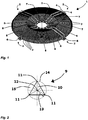
- Fig. 1 shows a perspective view of a protective device 1 according to the invention in the form of a protective grille which consists of four support struts 2 onto which concentric protective elements 3 in the form of grating rings are welded.
- Each support strut 2 consists of two parallel flat profiles 4, which are angled twice over the high edge at different angles, the inner ends of which are connected to an inner flange ring 5 and the outer ends of which are connected to an outer flange ring 6.
- the flat profiles 4 instead of the flat profiles 4, differently shaped profiles, for example round profiles, can also be used.
- two round struts 7 are arranged in the same division.
- the protective elements 3 are each connected at their intersection points (joints 8) with the flat profiles 4 and the round struts 7 by welding.
- the short line contact between protective element 3 and flat profile 4 is also regarded as a crossing point.
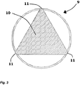
- Fig. 2 and Fig. 3 show front views of an elongated profile 9 of a protective element 3.
- the elongated profile 9 has a triangular cross-sectional area 10, wherein corner points 11 of the elongated profile 9 are located on a circumference 14 having a circumferential center 12 and a radius 13.
- the elongated profile 9 which can be a triangular wire, for example, about its longitudinal axis, which is perpendicular to the image plane and extends through the circumferential center 12
- the protective space formed by the elongated profile 9 increases, so that the initially twisted Condition given protection space, which is given by the edge length of the elongated profile 9, increases to the radius of the circumference 14.
- the triangular cross-sectional area 10 of the elongated profile 9 is only 41.3% of the area of a full round wire, the circumference of which is through Protection area is defined, corresponds to the radius 14, a material saving of 58.7% is achieved with the same protection area.
- the elongated profile 9 is shown as a solid material. It would be conceivable that instead of the elongated profile 9 made of solid material, an elongated hollow body (eg a triangular tube) with the same circumference is used. By using an elongated hollow body and twisting it, the material savings could be increased even further.
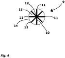
- the elongated profile 9 is designed as a star profile, which has a cross-sectional area 10.
- the corner points 11 of the star profile are located on a circumference 14 having a circumferential center point 12.
- the Fig. 5 shows a side view of an elongated profile 9 of a protective element 3 and the Fig. 6 shows a perspective view of an elongated profile 9 of a protective element 3 according to Fig. 2 with indicated cross-sectional areas 10.
- the elongated profile 9, which has a triangular cross-sectional area 10 is twisted about the longitudinal axis 16, as a result of which the protective space is enlarged.
- Fig. 7 shows a front view of an elongated profile 9 of a protective element 3 according to Fig. 2 with indicated cross-sectional areas 10.
- the twisting creates a surface structure that reduces the detachment of Kármán vertebrae, so that noise is counteracted.
Landscapes
- Engineering & Computer Science (AREA)
- Mechanical Engineering (AREA)
- General Engineering & Computer Science (AREA)
- Chemical & Material Sciences (AREA)
- Combustion & Propulsion (AREA)
- Structures Of Non-Positive Displacement Pumps (AREA)
- Prostheses (AREA)
- Devices Affording Protection Of Roads Or Walls For Sound Insulation (AREA)
- Professional, Industrial, Or Sporting Protective Garments (AREA)
Description
- Die Erfindung geht aus von einer Schutzvorrichtung, nach der Gattung des Anspruchs 1.
- Schutzvorrichtungen, die insbesondere für lüftungstechnische Anlagen eingesetzt werden, werden häufig aus konzentrisch um einen Mittelpunkt angeordneten Schutzelementen, wie z.B. Gitterringen, gebildet, die an Tragstreben fixiert sind und die mit ihrem Inneren einen Schutzraum bilden. Dabei darf der Abstand (Öffnung) zwischen den Schutzelementen, die als schützende Konstruktionen ein materielles Hindernis bieten, das insbesondere die Bewegung eines menschlichen Körpers und/oder eines Körperteils einschränkt, um das Erreichen eines Gefährdungsbereiches (z.B. ein rotierendes Laufrad) zu verhindern, aus sicherheitstechnischen Gründen nicht zu groß sein. Je nach Durchmesser der Schutzvorrichtung weisen daher herkömmliche Schutzvorrichtungen ein hohes Eigengewicht auf, da an ihnen eine Vielzahl von Schutzelementen angeordnet werden muss.
- Des Weiteren ist aus der Patentschrift
US 2001/0021344 A1 eine Schutzvorrichtung bekannt, die aus einem einstückigen Spritzgussteil gebildet wird. - Bei lüftungstechnischen Anlagen ist es zusätzlich oftmals erstrebenswert, dass sie einen hohen Luftdurchsatz aufweisen. Neben einer Vergrößerung der Lüftereinheit ist ein hoher Luftdurchsatz auch durch die Erhöhung der Strömungsgeschwindigkeit durch Erhöhung der Drehzahl der Lüftereinheit erzielbar. Mit zunehmender Strömungsgeschwindigkeit kann sich aber auf der strömungsabgewandten Seite des umströmten Schutzelementes eine Wirbelstraße, die gemäß ihrem Entdecker als Kármánsche Wirbelstraße bezeichnet wird, bilden, die aus zwei Reihen von Wirbeln mit entgegen gesetztem Drehsinn besteht. Der Charakter der Wirbelbildung wird im Wesentlichen von der Reynolds-Zahl, einer in der Strömungslehre für den Strömungszustand verwendete Kennzahl, bestimmt. Steigt die Strömungsgeschwindigkeit oder sinkt die Viskosität des Fluids (wie z.B. bei Luft im Vergleich zu Wasser) nimmt die Reynolds-Zahl zu. Mit zunehmender Reynolds-Zahl können sich diese Wirbel nicht mehr an dem Körper halten, und es löst sich abwechselnd oben und unten ein Wirbel ab, während sich der Wirbel auf der jeweils anderen Seite neu bildet. Aufgrund dieser abwechselnden Wirbelablösung ändert sich auch die Strömungsrichtung um den Zylinder periodisch. Durch diese Kräfte kann der umströmte Körper selbst zum Schwingen angeregt werden. Je nach Wirbelablösefrequenz kann ein hörbarer Ton entstehen, so dass eine Erhöhung der Strömungsgeschwindigkeit zu einer ungewünschten Geräuschbildung führen kann.
- Um diese Geräuschbildung zu reduzieren wird in der Patentschrift
US 6,866,474 B2 eine Schutzvorrichtung für ein Klimasystem vorgeschlagen, die Schutzelemente aufweist, wobei die Schutzelemente eine der Luftströmung zugewandte Kante aufweisen, durch deren Struktur die Ablösung von Kármán-Wirbeln reduziert wird. Nachteilig ist allerdings, dass die Strukturierung der Kante technisch aufwändig ist. Technisch aufwändig ist auch die Schutzvorrichtung, die in der der OffenlegungsschriftJP 2005 351546 A - Die Erfindung und ihre Vorteile Die erfindungsgemäße Schutzvorrichtung wird von Anspruch 1 definiert. Diese Vorrichtung hat den Vorteil, dass sie mindestens ein Schutzelement, das ein längliches, im Querschnitt ein Polygon aufweisendes, verdrilltes Profil umfasst, aufweist, wobei die geometrische Gestaltung des Schutzelementes die verbaute Masse deutlich reduziert, so dass es zu einer Gewichtsreduzierung kommt. Zusätzlich kann die geometrische Gestaltung des Schutzelementes ggfls. die Ablösung von Kármán-Wirbeln und damit die Geräuschentwicklung reduzieren.
Nach einer vorteilhaften Ausgestaltung der erfindungsgemäßen Schutzvorrichtung ist das längliche Profil eines Schutzelementes aus Vollmaterial.
Nach einer zusätzlichen vorteilhaften Ausgestaltung der erfindungsgemäßen Schutzvorrichtung ist das längliche Profil eines Schutzelementes ein Hohlkörper (z.B. ein dreieckiges oder viereckiges Rohr).
Nach einer zusätzlichen vorteilhaften Ausgestaltung der erfindungsgemäßen Schutzvorrichtung befindet sich der Umkreismittelpunkt des länglichen Profils auf der Längsachse des länglichen Profils.
Nach einer zusätzlichen vorteilhaften Ausgestaltung der erfindungsgemäßen Schutzvorrichtung weist ein Schutzelement unterschiedliche Verdrillwinkel und/oder unterschiedliche Verdrillstetigkeiten auf.
Nach einer zusätzlichen vorteilhaften Ausgestaltung der erfindungsgemäßen Schutzvorrichtung weisen mehrere Schutzelemente unterschiedliche Verdrillwinkel und/oder unterschiedliche Verdrillstetigkeiten auf. - Nach einer vorteilhaften Ausgestaltung der erfindungsgemäßen Schutzvorrichtung ist das Polygon ein Dreieck, Viereck, Vieleck oder ein Sternprofil.
Nach einer diesbezüglichen vorteilhaften Ausgestaltung der erfindungsgemäßen Schutzvorrichtung ist das Dreieck ein gleichseitiges Dreieck oder das Vieleck ein regelmäßiges Vieleck. - Nach einer zusätzlichen vorteilhaften Ausgestaltung der erfindungsgemäßen Schutzvorrichtung weist die Schutzvorrichtung mehrere zueinander beabstandet angeordnete Schutzelemente auf. Somit entspricht der Abstand (Öffnung), der zwischen zwei Schutzelementen vorhanden ist, dem Abstand, der zwischen den beiden den jeweiligen Schutzraum begrenzenden Begrenzungen vorhanden ist. Bei einem verdrillten länglichen Profil, das auf einem Umkreis liegende Eckpunkte aufweist, wird der Schutzraum durch den Umkreis begrenzt. Somit entspricht der Abstand (Öffnung) zwischen zwei länglichen Profilen dem Abstand zwischen deren Umkreisen. Bei unverdrillten Rundrohren, deren Schutzraum durch den Außenumfang des Rundrohres begrenzt wird, entspricht der Abstand (Öffnung) zwischen den Rundrohren dem Abstand zwischen den Außenumfängen.
- Nach einer zusätzlichen vorteilhaften Ausgestaltung der erfindungsgemäßen Schutzvorrichtung ist die Schutzvorrichtung als Schutzgitter und/oder als Motoraufhängung ausgebildet.
Weitere Vorteile und vorteilhafte Ausgestaltungen der Erfindung sind der nachfolgenden Beschreibung, der Zeichnung und den Ansprüchen entnehmbar. - Ausführungsbeispiele des Gegenstandes der Erfindung sind in der Zeichnung dargestellt und werden im Folgenden näher erläutert. Es zeigen:
- Fig. 1
- eine perspektivische Ansicht einer erfindungsgemäßen Schutzvorrichtung in Form eines Schutzgitters,
- Fig. 2 und 3
- eine Frontansicht auf ein längliches Profil eines Schutzelementes,
- Fig. 4
- eine Frontansicht auf ein anderes längliches Profil eines Schutzelementes, das nicht Teil der Erfindung ist,
- Fig. 5
- eine Seitenansicht auf ein längliches Profil eines Schutzelementes gemäß
Fig. 2 ; - Fig. 6
- eine Seitenansicht auf ein längliches Profil eines Schutzelementes gemäß
Fig. 2 mit angedeuteten Querschnittsflächen und - Fig. 7
- eine Frontansicht auf ein längliches Profil eines Schutzelementes gemäß
Fig. 2 mit angedeuteten Querschnittsflächen. -
Fig. 1 zeigt eine perspektivische Ansicht einer erfindungsgemäßen Schutzvorrichtung 1 in Form eines Schutzgitters, das aus vier Tragstreben 2 besteht, auf die konzentrische Schutzelemente 3 in Form von Gitterringen aufgeschweißt sind. Jede Tragstrebe 2 besteht aus zwei parallel geführten, zweimal über die hohe Kante mit unterschiedlichen Winkeln abgewinkelten Flachprofilen 4, deren innere Enden mit einem inneren Flanschring 5 und deren äußere Enden zu einem äußeren Flanschring 6 miteinander verbunden sind. Selbstverständlich können anstatt der Flachprofile 4 auch anders gestaltete Profile, beispielsweise Rundprofile, eingesetzt werden. Zwischen den Tragstreben 2 sind in gleicher Teilung jeweils zwei Rundstreben 7 angeordnet. Die Schutzelemente 3 sind jeweils an ihren Kreuzungspunkten (Fügestellen 8) mit den Flachprofilen 4 und den Rundstreben 7 durch Schweißen miteinander verbunden. Der Einfachheit halber wird auch die kurze Linienberührung zwischen Schutzelement 3 und Flachprofil 4 als ein Kreuzungspunkt angesehen. -
Fig. 2 undFig. 3 zeigen Frontansichten auf ein längliches Profil 9 eines Schutzelementes 3. Das längliche Profil 9 weist eine dreieckige Querschnittsfläche 10 auf, wobei sich Eckpunkte 11 des länglichen Profils 9 auf einem einen Umkreismittelpunkt 12 und einen Radius 13 aufweisenden Umkreis 14 befinden. Durch Verdrillung des länglichen Profils 9, das beispielsweise ein dreieckiger Draht sein kann, um seine Längsachse, die senkrecht auf der Bildebene steht und durch den Umkreismittelpunkt 12 verläuft, vergrößert sich der durch das längliche Profil 9 gebildete Schutzraum, so dass sich der anfänglich im unverdrillten Zustand gegebene Schutzraum, der durch die Kantenlänge des länglichen Profils 9 gegeben ist, vergrößert auf den Radius des Umkreises 14. Da die dreieckige Querschnittsfläche 10 des länglichen Profils 9 lediglich 41,3 % der Fläche eines vollen Rundrahtes beträgt, dessen Umfang, durch den sein Schutzraum festgelegt wird, dem Umkreis 14 entspricht, wird bei gleichem Schutzraum eine Materialeinsparung von 58,7 % erzielt.
InFig. 2 undFig. 3 ist das längliche Profil 9 als Vollmaterial dargestellt. Denkbar wäre, dass anstatt des aus Vollmaterial bestehenden länglichen Profils 9 ein den gleichen Umfang aufweisender länglicher Hohlkörper (z.B. ein dreieckiges Rohr) eingesetzt wird. Durch den Einsatz eines länglichen Hohlkörpers und durch dessen Verdrillung könnte die Materialeinsparung noch weiter erhöht werden.
Fig. 4 zeigt eine Frontansicht auf ein anderes längliches Profil 9 eines Schutzelementes 3, das jedoch nicht Teil der Erfindung ist. Das längliche Profil 9 ist als Sternprofil ausgestaltet, das eine Querschnittsfläche 10 aufweist. Die Eckpunkte 11 des Sternprofils befinden sich auf einem einen Umkreismittelpunkt 12 aufweisenden Umkreis 14. Durch Verdrillung des Sternprofils um seine Längsachse, die senkrecht auf der Bildebene steht und durch den Umkreismittelpunkt 12 verläuft, vergrößert sich der durch das Sternprofil gebildete Schutzraum, so dass der anfänglich im unverdrillten Zustand gegebene Schutzraum, der der Querschnittsfläche 10 entsprach, nun durch die Kreisfläche 15 des Umkreises 14 gegeben ist. - Da die Querschnittsfläche 10 des Sternprofils lediglich einen Bruchteil der Fläche eines vollen Rundrahtes beträgt, dessen Umfang, durch den sein Schutzraum festgelegt wird, dem Umkreis 14 entspricht, wird bei gleicher Fläche des Schutzraumes eine Materialeinsparung erzielt.
DieFig. 5 zeigt eine Seitenansicht eines länglichen Profils 9 eines Schutzelementes 3 und dieFig. 6 zeigt eine perspektivische Ansicht auf ein längliches Profil 9 eines Schutzelementes 3 gemäßFig. 2 mit angedeuteten Querschnittsflächen 10. Das längliche Profil 9, das eine dreieckige Querschnittsfläche 10 aufweist, ist um die Längsachse 16 verdrillt, wodurch der Schutzraum vergrößert wird.
Fig. 7 zeigt eine Frontansicht auf ein längliches Profil 9 eines Schutzelementes 3 gemäßFig. 2 mit angedeuteten Querschnittsflächen 10.
Zusätzlich wird durch die Verdrillung eine Oberflächenstruktur geschaffen, durch die die Ablösung von Kármán-Wirbeln reduziert wird, so dass einer Geräuschbildung entgegen gewirkt wird. -
- 1
- Schutzvorrichtung
- 2
- Tragstrebe
- 3
- Gitterring
- 4
- Flachprofil
- 5
- Innerer Flanschring
- 6
- Äußerer Flanschring
- 7
- Rundstrebe
- 8
- Fügestelle
- 9
- Längliches Profil
- 10
- Querschnittsfläche
- 11
- Eckpunkt
- 12
- Umkreismittelpunkt
- 13
- Radius
- 14
- Umkreis
- 15
- Kreisfläche
- 16
- Längsachse
Claims (9)
- Schutzvorrichtung (1) für eine lüftungstechnische Anlage,- mit mindestens einer Tragstrebe (2),- mit mindestens einem Schutzelement (3) und- mit einem durch das Schutzelement (3) gebildeten Schutzraum,wobei mindestens ein Schutzelement (3) an mindestens einem Kreuzungspunkt mit mindestens einer Tragstrebe (2) verbunden ist, wobei die Schutzvorrichtung (1) einen Mittelpunkt aufweist, um den mindestens ein Schutzelement (3) spiralförmig und/oder mindestens ein Schutzelement (3) ringförmig angeordnet sind,
wobei mindestens ein Schutzelement (3) als längliches Profil (9) ausgebildet ist, dessen Querschnitt ein Polygon ist und mindestens zwei Eckpunkte (11) aufweist, die sich auf einem einen Umkreismittelpunkt (12) aufweisenden Umkreis (14) befinden, und das um seine Längsachse zur Bildung eines Schutzraumes verdrillt ist,
wobei dieses verdrillte Schutzelement auf der Tragstrebe aufgeschweißt ist. - Schutzvorrichtung (1), nach Anspruch 1, dadurch gekennzeichnet, dass das längliche Profil (9) des Schutzelementes (3) aus Vollmaterial ist.
- Schutzvorrichtung (1), nach Anspruch 1, dadurch gekennzeichnet, dass das längliche Profil (9) des Schutzelementes (3) ein Hohlkörper ist.
- Schutzvorrichtung (1), nach einem der vorhergehenden Ansprüche, dadurch gekennzeichnet, dass das Schutzelement (3) unterschiedliche Verdrillwinkel und/oder unterschiedliche Verdrillstetigkeiten aufweist.
- Schutzvorrichtung (1), nach einem der vorhergehenden Ansprüche, dadurch gekennzeichnet, dass mehrere Schutzelemente (3) unterschiedliche Verdrillwinkel und/oder unterschiedliche Verdrillstetigkeiten aufweisen.
- Schutzvorrichtung (1), nach einem der vorhergehenden Ansprüche, dadurch gekennzeichnet, dass das Polygon ein Dreieck, Viereck, Vieleck oder ein Sternprofil ist.
- Schutzvorrichtung (1), nach Anspruch 6, dadurch gekennzeichnet, dass das Dreieck ein gleichseitiges Dreieck oder das Vieleck ein regelmäßiges Vieleck ist.
- Schutzvorrichtung (1), nach einem der vorhergehenden Ansprüche, dadurch gekennzeichnet, dass die Schutzvorrichtung (1) mehrere zueinander beabstandet angeordnete Schutzelemente (3) aufweist.
- Schutzvorrichtung (1), nach einem der vorhergehenden Ansprüche, dadurch gekennzeichnet, dass die Schutzvorrichtung (1) als Schutzgitter und/oder als Motoraufhängung ausgebildet ist.
Applications Claiming Priority (2)
| Application Number | Priority Date | Filing Date | Title |
|---|---|---|---|
| DE102012020245.8A DE102012020245B4 (de) | 2012-10-11 | 2012-10-11 | Schutzvorrichtung |
| PCT/DE2013/000438 WO2014056467A1 (de) | 2012-10-11 | 2013-08-06 | Lüfter-schutzgitter mit verdrillten stäben mit polygonalem querschnitt zur reduzierung des karmanschen wirbelablösungsgeräusches |
Publications (2)
| Publication Number | Publication Date |
|---|---|
| EP2906832A1 EP2906832A1 (de) | 2015-08-19 |
| EP2906832B1 true EP2906832B1 (de) | 2020-03-18 |
Family
ID=49225981
Family Applications (1)
| Application Number | Title | Priority Date | Filing Date |
|---|---|---|---|
| EP13765619.5A Active EP2906832B1 (de) | 2012-10-11 | 2013-08-06 | Lüfter-schutzgitter mit verdrillten stäben mit polygonalem querschnitt zur reduzierung des karmanschen wirbelablösungsgeräusches |
Country Status (4)
| Country | Link |
|---|---|
| EP (1) | EP2906832B1 (de) |
| DE (1) | DE102012020245B4 (de) |
| HU (1) | HUE050270T2 (de) |
| WO (1) | WO2014056467A1 (de) |
Families Citing this family (1)
| Publication number | Priority date | Publication date | Assignee | Title |
|---|---|---|---|---|
| US20190368753A1 (en) * | 2017-02-23 | 2019-12-05 | Mitsubishi Electric Corporation | Outdoor unit for air-conditioning apparatus |
Citations (1)
| Publication number | Priority date | Publication date | Assignee | Title |
|---|---|---|---|---|
| DE202004006011U1 (de) * | 2004-04-16 | 2004-08-19 | Rödel, Günter | Haushaltsventilator mit Kühlaggregat über das Schutzgitter |
Family Cites Families (8)
| Publication number | Priority date | Publication date | Assignee | Title |
|---|---|---|---|---|
| US5214244A (en) * | 1988-10-28 | 1993-05-25 | Science Applications International Corporation | Strumming resistant cable |
| US5259726A (en) * | 1992-06-26 | 1993-11-09 | Storage Technology Corporation | Rotating fan guard |
| JP3741255B2 (ja) * | 2000-03-10 | 2006-02-01 | 株式会社丸山製作所 | 遠心送風機及び携帯型作業機 |
| US6470700B1 (en) * | 2002-01-24 | 2002-10-29 | Carrier Corporation | Reduced noise grill |
| US6866474B2 (en) | 2003-01-27 | 2005-03-15 | Lennox Industries, Inc. | Noise reduction by vortex suppression in air flow systems |
| JP4253618B2 (ja) * | 2004-06-10 | 2009-04-15 | ヤンマー株式会社 | ファンガード |
| JP2009085562A (ja) * | 2007-10-03 | 2009-04-23 | Yanmar Co Ltd | ファンガード |
| DE102009025025A1 (de) * | 2008-06-12 | 2009-12-17 | Stadtmüller, Uwe | Räumliches Schutzgitter für Axiallüfter und Verfahren zur Herstellung des Schutzgitters |
-
2012
- 2012-10-11 DE DE102012020245.8A patent/DE102012020245B4/de active Active
-
2013
- 2013-08-06 HU HUE13765619A patent/HUE050270T2/hu unknown
- 2013-08-06 WO PCT/DE2013/000438 patent/WO2014056467A1/de not_active Ceased
- 2013-08-06 EP EP13765619.5A patent/EP2906832B1/de active Active
Patent Citations (1)
| Publication number | Priority date | Publication date | Assignee | Title |
|---|---|---|---|---|
| DE202004006011U1 (de) * | 2004-04-16 | 2004-08-19 | Rödel, Günter | Haushaltsventilator mit Kühlaggregat über das Schutzgitter |
Also Published As
| Publication number | Publication date |
|---|---|
| DE102012020245B4 (de) | 2015-01-15 |
| EP2906832A1 (de) | 2015-08-19 |
| DE102012020245A1 (de) | 2014-04-17 |
| WO2014056467A1 (de) | 2014-04-17 |
| HUE050270T2 (hu) | 2020-11-30 |
Similar Documents
| Publication | Publication Date | Title |
|---|---|---|
| DE102012112415B4 (de) | Übergangskörper zur Anordnung zwischen unterschiedlich ausgeführten Abschnitten eines Windkraftanlagenturms und Windkraftanlagenturm mit einem solchen Übergangskörper | |
| EP2815130B1 (de) | Diffusor, ventilator mit einem solchen diffusor sowie gerät mit solchen ventilatoren | |
| EP2525128B1 (de) | Übergangsstück | |
| EP3298284B1 (de) | Ebenes strömungsleitgitter | |
| EP3215745A1 (de) | Schutzgitter mit verbessertem wirkungsgrad- und geräuschverhalten | |
| DE102011121025A1 (de) | Motoraufhängung für Ventilatoren, vorzugsweise Axialventilatoren, sowie Verfahren zur Herstellung eines Lüftungsgitters einer solchen Motoraufhängung | |
| EP2195530B1 (de) | Mastkonstruktion für fachwerk-türme von windkraftanlagen | |
| EP2455305A1 (de) | Silo | |
| EP3377190B1 (de) | Filterscheibe | |
| DE102012020245B4 (de) | Schutzvorrichtung | |
| EP3268654B1 (de) | Dämpfungsvorrichtung | |
| EP2520872B1 (de) | Solarturmkraftwerk-Solarempfänger | |
| DE102015003859A1 (de) | Ausbläser | |
| EP2513389A1 (de) | Teleskopierbare baustütze | |
| AT507013B1 (de) | Mast für eine mit einem darrieus-rotor ausgestattete windenergieanlage | |
| DE202014103877U1 (de) | Schutzgitter für einen Ventilator | |
| DE102009038743A1 (de) | Schälscheibe einer Zentrifuge | |
| EP4341513A1 (de) | Spindelstrebe | |
| EP1457263B1 (de) | Schälscheibe für eine Zentrifuge | |
| DE4243932C2 (de) | Schutzgitter für Freispiegelgerinne | |
| EP3896234A1 (de) | Armaturenanordnung | |
| WO2025045728A1 (de) | Vorrichtung zur reduktion wirbelinduzierter schwingungen eines fluidumströmten körpers | |
| EP3032133B1 (de) | Faltenbalgluftfeder mit Abstandsring | |
| WO2000076890A1 (de) | Krümmerelement | |
| DE102011077938B4 (de) | Dampfsiebanordnung und Verwendung einer Dampfsiebanordnung |
Legal Events
| Date | Code | Title | Description |
|---|---|---|---|
| PUAI | Public reference made under article 153(3) epc to a published international application that has entered the european phase |
Free format text: ORIGINAL CODE: 0009012 |
|
| 17P | Request for examination filed |
Effective date: 20150507 |
|
| AK | Designated contracting states |
Kind code of ref document: A1 Designated state(s): AL AT BE BG CH CY CZ DE DK EE ES FI FR GB GR HR HU IE IS IT LI LT LU LV MC MK MT NL NO PL PT RO RS SE SI SK SM TR |
|
| AX | Request for extension of the european patent |
Extension state: BA ME |
|
| STAA | Information on the status of an ep patent application or granted ep patent |
Free format text: STATUS: EXAMINATION IS IN PROGRESS |
|
| 17Q | First examination report despatched |
Effective date: 20180409 |
|
| GRAP | Despatch of communication of intention to grant a patent |
Free format text: ORIGINAL CODE: EPIDOSNIGR1 |
|
| STAA | Information on the status of an ep patent application or granted ep patent |
Free format text: STATUS: GRANT OF PATENT IS INTENDED |
|
| INTG | Intention to grant announced |
Effective date: 20191209 |
|
| GRAS | Grant fee paid |
Free format text: ORIGINAL CODE: EPIDOSNIGR3 |
|
| GRAA | (expected) grant |
Free format text: ORIGINAL CODE: 0009210 |
|
| STAA | Information on the status of an ep patent application or granted ep patent |
Free format text: STATUS: THE PATENT HAS BEEN GRANTED |
|
| AK | Designated contracting states |
Kind code of ref document: B1 Designated state(s): AL AT BE BG CH CY CZ DE DK EE ES FI FR GB GR HR HU IE IS IT LI LT LU LV MC MK MT NL NO PL PT RO RS SE SI SK SM TR |
|
| AX | Request for extension of the european patent |
Extension state: BA ME |
|
| REG | Reference to a national code |
Ref country code: GB Ref legal event code: FG4D Free format text: NOT ENGLISH |
|
| REG | Reference to a national code |
Ref country code: DE Ref legal event code: R096 Ref document number: 502013014465 Country of ref document: DE |
|
| REG | Reference to a national code |
Ref country code: AT Ref legal event code: REF Ref document number: 1246206 Country of ref document: AT Kind code of ref document: T Effective date: 20200415 Ref country code: IE Ref legal event code: FG4D Free format text: LANGUAGE OF EP DOCUMENT: GERMAN |
|
| PG25 | Lapsed in a contracting state [announced via postgrant information from national office to epo] |
Ref country code: FI Free format text: LAPSE BECAUSE OF FAILURE TO SUBMIT A TRANSLATION OF THE DESCRIPTION OR TO PAY THE FEE WITHIN THE PRESCRIBED TIME-LIMIT Effective date: 20200318 Ref country code: RS Free format text: LAPSE BECAUSE OF FAILURE TO SUBMIT A TRANSLATION OF THE DESCRIPTION OR TO PAY THE FEE WITHIN THE PRESCRIBED TIME-LIMIT Effective date: 20200318 Ref country code: NO Free format text: LAPSE BECAUSE OF FAILURE TO SUBMIT A TRANSLATION OF THE DESCRIPTION OR TO PAY THE FEE WITHIN THE PRESCRIBED TIME-LIMIT Effective date: 20200618 |
|
| REG | Reference to a national code |
Ref country code: NL Ref legal event code: MP Effective date: 20200318 |
|
| PG25 | Lapsed in a contracting state [announced via postgrant information from national office to epo] |
Ref country code: HR Free format text: LAPSE BECAUSE OF FAILURE TO SUBMIT A TRANSLATION OF THE DESCRIPTION OR TO PAY THE FEE WITHIN THE PRESCRIBED TIME-LIMIT Effective date: 20200318 Ref country code: GR Free format text: LAPSE BECAUSE OF FAILURE TO SUBMIT A TRANSLATION OF THE DESCRIPTION OR TO PAY THE FEE WITHIN THE PRESCRIBED TIME-LIMIT Effective date: 20200619 Ref country code: LV Free format text: LAPSE BECAUSE OF FAILURE TO SUBMIT A TRANSLATION OF THE DESCRIPTION OR TO PAY THE FEE WITHIN THE PRESCRIBED TIME-LIMIT Effective date: 20200318 Ref country code: SE Free format text: LAPSE BECAUSE OF FAILURE TO SUBMIT A TRANSLATION OF THE DESCRIPTION OR TO PAY THE FEE WITHIN THE PRESCRIBED TIME-LIMIT Effective date: 20200318 Ref country code: BG Free format text: LAPSE BECAUSE OF FAILURE TO SUBMIT A TRANSLATION OF THE DESCRIPTION OR TO PAY THE FEE WITHIN THE PRESCRIBED TIME-LIMIT Effective date: 20200618 |
|
| REG | Reference to a national code |
Ref country code: LT Ref legal event code: MG4D |
|
| PG25 | Lapsed in a contracting state [announced via postgrant information from national office to epo] |
Ref country code: NL Free format text: LAPSE BECAUSE OF FAILURE TO SUBMIT A TRANSLATION OF THE DESCRIPTION OR TO PAY THE FEE WITHIN THE PRESCRIBED TIME-LIMIT Effective date: 20200318 |
|
| PG25 | Lapsed in a contracting state [announced via postgrant information from national office to epo] |
Ref country code: CZ Free format text: LAPSE BECAUSE OF FAILURE TO SUBMIT A TRANSLATION OF THE DESCRIPTION OR TO PAY THE FEE WITHIN THE PRESCRIBED TIME-LIMIT Effective date: 20200318 Ref country code: RO Free format text: LAPSE BECAUSE OF FAILURE TO SUBMIT A TRANSLATION OF THE DESCRIPTION OR TO PAY THE FEE WITHIN THE PRESCRIBED TIME-LIMIT Effective date: 20200318 Ref country code: SK Free format text: LAPSE BECAUSE OF FAILURE TO SUBMIT A TRANSLATION OF THE DESCRIPTION OR TO PAY THE FEE WITHIN THE PRESCRIBED TIME-LIMIT Effective date: 20200318 Ref country code: IS Free format text: LAPSE BECAUSE OF FAILURE TO SUBMIT A TRANSLATION OF THE DESCRIPTION OR TO PAY THE FEE WITHIN THE PRESCRIBED TIME-LIMIT Effective date: 20200718 Ref country code: PT Free format text: LAPSE BECAUSE OF FAILURE TO SUBMIT A TRANSLATION OF THE DESCRIPTION OR TO PAY THE FEE WITHIN THE PRESCRIBED TIME-LIMIT Effective date: 20200812 Ref country code: LT Free format text: LAPSE BECAUSE OF FAILURE TO SUBMIT A TRANSLATION OF THE DESCRIPTION OR TO PAY THE FEE WITHIN THE PRESCRIBED TIME-LIMIT Effective date: 20200318 Ref country code: EE Free format text: LAPSE BECAUSE OF FAILURE TO SUBMIT A TRANSLATION OF THE DESCRIPTION OR TO PAY THE FEE WITHIN THE PRESCRIBED TIME-LIMIT Effective date: 20200318 Ref country code: SM Free format text: LAPSE BECAUSE OF FAILURE TO SUBMIT A TRANSLATION OF THE DESCRIPTION OR TO PAY THE FEE WITHIN THE PRESCRIBED TIME-LIMIT Effective date: 20200318 |
|
| REG | Reference to a national code |
Ref country code: HU Ref legal event code: AG4A Ref document number: E050270 Country of ref document: HU |
|
| REG | Reference to a national code |
Ref country code: DE Ref legal event code: R097 Ref document number: 502013014465 Country of ref document: DE |
|
| PLBE | No opposition filed within time limit |
Free format text: ORIGINAL CODE: 0009261 |
|
| STAA | Information on the status of an ep patent application or granted ep patent |
Free format text: STATUS: NO OPPOSITION FILED WITHIN TIME LIMIT |
|
| PG25 | Lapsed in a contracting state [announced via postgrant information from national office to epo] |
Ref country code: DK Free format text: LAPSE BECAUSE OF FAILURE TO SUBMIT A TRANSLATION OF THE DESCRIPTION OR TO PAY THE FEE WITHIN THE PRESCRIBED TIME-LIMIT Effective date: 20200318 Ref country code: ES Free format text: LAPSE BECAUSE OF FAILURE TO SUBMIT A TRANSLATION OF THE DESCRIPTION OR TO PAY THE FEE WITHIN THE PRESCRIBED TIME-LIMIT Effective date: 20200318 |
|
| 26N | No opposition filed |
Effective date: 20201221 |
|
| PG25 | Lapsed in a contracting state [announced via postgrant information from national office to epo] |
Ref country code: PL Free format text: LAPSE BECAUSE OF FAILURE TO SUBMIT A TRANSLATION OF THE DESCRIPTION OR TO PAY THE FEE WITHIN THE PRESCRIBED TIME-LIMIT Effective date: 20200318 |
|
| REG | Reference to a national code |
Ref country code: DE Ref legal event code: R119 Ref document number: 502013014465 Country of ref document: DE |
|
| PG25 | Lapsed in a contracting state [announced via postgrant information from national office to epo] |
Ref country code: MC Free format text: LAPSE BECAUSE OF FAILURE TO SUBMIT A TRANSLATION OF THE DESCRIPTION OR TO PAY THE FEE WITHIN THE PRESCRIBED TIME-LIMIT Effective date: 20200318 |
|
| REG | Reference to a national code |
Ref country code: CH Ref legal event code: PL |
|
| GBPC | Gb: european patent ceased through non-payment of renewal fee |
Effective date: 20200806 |
|
| PG25 | Lapsed in a contracting state [announced via postgrant information from national office to epo] |
Ref country code: LI Free format text: LAPSE BECAUSE OF NON-PAYMENT OF DUE FEES Effective date: 20200831 Ref country code: CH Free format text: LAPSE BECAUSE OF NON-PAYMENT OF DUE FEES Effective date: 20200831 Ref country code: LU Free format text: LAPSE BECAUSE OF NON-PAYMENT OF DUE FEES Effective date: 20200806 |
|
| REG | Reference to a national code |
Ref country code: BE Ref legal event code: MM Effective date: 20200831 |
|
| PG25 | Lapsed in a contracting state [announced via postgrant information from national office to epo] |
Ref country code: SI Free format text: LAPSE BECAUSE OF FAILURE TO SUBMIT A TRANSLATION OF THE DESCRIPTION OR TO PAY THE FEE WITHIN THE PRESCRIBED TIME-LIMIT Effective date: 20200318 |
|
| PG25 | Lapsed in a contracting state [announced via postgrant information from national office to epo] |
Ref country code: DE Free format text: LAPSE BECAUSE OF NON-PAYMENT OF DUE FEES Effective date: 20210302 Ref country code: FR Free format text: LAPSE BECAUSE OF NON-PAYMENT OF DUE FEES Effective date: 20200831 |
|
| PG25 | Lapsed in a contracting state [announced via postgrant information from national office to epo] |
Ref country code: BE Free format text: LAPSE BECAUSE OF NON-PAYMENT OF DUE FEES Effective date: 20200831 Ref country code: IE Free format text: LAPSE BECAUSE OF NON-PAYMENT OF DUE FEES Effective date: 20200806 Ref country code: GB Free format text: LAPSE BECAUSE OF NON-PAYMENT OF DUE FEES Effective date: 20200806 |
|
| REG | Reference to a national code |
Ref country code: AT Ref legal event code: MM01 Ref document number: 1246206 Country of ref document: AT Kind code of ref document: T Effective date: 20200806 |
|
| PG25 | Lapsed in a contracting state [announced via postgrant information from national office to epo] |
Ref country code: AT Free format text: LAPSE BECAUSE OF NON-PAYMENT OF DUE FEES Effective date: 20200806 |
|
| PG25 | Lapsed in a contracting state [announced via postgrant information from national office to epo] |
Ref country code: TR Free format text: LAPSE BECAUSE OF FAILURE TO SUBMIT A TRANSLATION OF THE DESCRIPTION OR TO PAY THE FEE WITHIN THE PRESCRIBED TIME-LIMIT Effective date: 20200318 Ref country code: MT Free format text: LAPSE BECAUSE OF FAILURE TO SUBMIT A TRANSLATION OF THE DESCRIPTION OR TO PAY THE FEE WITHIN THE PRESCRIBED TIME-LIMIT Effective date: 20200318 Ref country code: CY Free format text: LAPSE BECAUSE OF FAILURE TO SUBMIT A TRANSLATION OF THE DESCRIPTION OR TO PAY THE FEE WITHIN THE PRESCRIBED TIME-LIMIT Effective date: 20200318 |
|
| PG25 | Lapsed in a contracting state [announced via postgrant information from national office to epo] |
Ref country code: MK Free format text: LAPSE BECAUSE OF FAILURE TO SUBMIT A TRANSLATION OF THE DESCRIPTION OR TO PAY THE FEE WITHIN THE PRESCRIBED TIME-LIMIT Effective date: 20200318 Ref country code: AL Free format text: LAPSE BECAUSE OF FAILURE TO SUBMIT A TRANSLATION OF THE DESCRIPTION OR TO PAY THE FEE WITHIN THE PRESCRIBED TIME-LIMIT Effective date: 20200318 |
|
| REG | Reference to a national code |
Ref country code: HU Ref legal event code: GB9C Owner name: EBM-PAPST MULFINGEN GMBH & CO.KG, DE Free format text: FORMER OWNER(S): STADTMUELLER, UWE, DE Ref country code: HU Ref legal event code: FH1C Free format text: FORMER REPRESENTATIVE(S): DANUBIA SZABADALMI ES JOGI IRODA KFT., HU Representative=s name: DANUBIA SZABADALMI ES JOGI IRODA KFT., HU |
|
| PGFP | Annual fee paid to national office [announced via postgrant information from national office to epo] |
Ref country code: HU Payment date: 20250804 Year of fee payment: 13 |
|
| PGFP | Annual fee paid to national office [announced via postgrant information from national office to epo] |
Ref country code: IT Payment date: 20250829 Year of fee payment: 13 |