EP2906815B1 - Valve for a pump - Google Patents
Valve for a pump Download PDFInfo
- Publication number
- EP2906815B1 EP2906815B1 EP13788688.3A EP13788688A EP2906815B1 EP 2906815 B1 EP2906815 B1 EP 2906815B1 EP 13788688 A EP13788688 A EP 13788688A EP 2906815 B1 EP2906815 B1 EP 2906815B1
- Authority
- EP
- European Patent Office
- Prior art keywords
- valve
- armature
- spherical surface
- valve according
- channel
- Prior art date
- Legal status (The legal status is an assumption and is not a legal conclusion. Google has not performed a legal analysis and makes no representation as to the accuracy of the status listed.)
- Active
Links
Images

Classifications
-
- F—MECHANICAL ENGINEERING; LIGHTING; HEATING; WEAPONS; BLASTING
- F02—COMBUSTION ENGINES; HOT-GAS OR COMBUSTION-PRODUCT ENGINE PLANTS
- F02M—SUPPLYING COMBUSTION ENGINES IN GENERAL WITH COMBUSTIBLE MIXTURES OR CONSTITUENTS THEREOF
- F02M59/00—Pumps specially adapted for fuel-injection and not provided for in groups F02M39/00 -F02M57/00, e.g. rotary cylinder-block type of pumps
- F02M59/44—Details, components parts, or accessories not provided for in, or of interest apart from, the apparatus of groups F02M59/02 - F02M59/42; Pumps having transducers, e.g. to measure displacement of pump rack or piston
- F02M59/46—Valves
- F02M59/466—Electrically operated valves, e.g. using electromagnetic or piezoelectric operating means
-
- F—MECHANICAL ENGINEERING; LIGHTING; HEATING; WEAPONS; BLASTING
- F02—COMBUSTION ENGINES; HOT-GAS OR COMBUSTION-PRODUCT ENGINE PLANTS
- F02M—SUPPLYING COMBUSTION ENGINES IN GENERAL WITH COMBUSTIBLE MIXTURES OR CONSTITUENTS THEREOF
- F02M59/00—Pumps specially adapted for fuel-injection and not provided for in groups F02M39/00 -F02M57/00, e.g. rotary cylinder-block type of pumps
- F02M59/20—Varying fuel delivery in quantity or timing
- F02M59/36—Varying fuel delivery in quantity or timing by variably-timed valves controlling fuel passages to pumping elements or overflow passages
- F02M59/366—Valves being actuated electrically
- F02M59/368—Pump inlet valves being closed when actuated
-
- F—MECHANICAL ENGINEERING; LIGHTING; HEATING; WEAPONS; BLASTING
- F02—COMBUSTION ENGINES; HOT-GAS OR COMBUSTION-PRODUCT ENGINE PLANTS
- F02M—SUPPLYING COMBUSTION ENGINES IN GENERAL WITH COMBUSTIBLE MIXTURES OR CONSTITUENTS THEREOF
- F02M63/00—Other fuel-injection apparatus having pertinent characteristics not provided for in groups F02M39/00 - F02M57/00 or F02M67/00; Details, component parts, or accessories of fuel-injection apparatus, not provided for in, or of interest apart from, the apparatus of groups F02M39/00 - F02M61/00 or F02M67/00; Combination of fuel pump with other devices, e.g. lubricating oil pump
- F02M63/0012—Valves
- F02M63/0031—Valves characterized by the type of valves, e.g. special valve member details, valve seat details, valve housing details
- F02M63/0033—Lift valves, i.e. having a valve member that moves perpendicularly to the plane of the valve seat
- F02M63/0035—Poppet valves, i.e. having a mushroom-shaped valve member that moves perpendicularly to the plane of the valve seat
-
- F—MECHANICAL ENGINEERING; LIGHTING; HEATING; WEAPONS; BLASTING
- F02—COMBUSTION ENGINES; HOT-GAS OR COMBUSTION-PRODUCT ENGINE PLANTS
- F02M—SUPPLYING COMBUSTION ENGINES IN GENERAL WITH COMBUSTIBLE MIXTURES OR CONSTITUENTS THEREOF
- F02M63/00—Other fuel-injection apparatus having pertinent characteristics not provided for in groups F02M39/00 - F02M57/00 or F02M67/00; Details, component parts, or accessories of fuel-injection apparatus, not provided for in, or of interest apart from, the apparatus of groups F02M39/00 - F02M61/00 or F02M67/00; Combination of fuel pump with other devices, e.g. lubricating oil pump
- F02M63/0012—Valves
- F02M63/0031—Valves characterized by the type of valves, e.g. special valve member details, valve seat details, valve housing details
- F02M63/0033—Lift valves, i.e. having a valve member that moves perpendicularly to the plane of the valve seat
- F02M63/0036—Lift valves, i.e. having a valve member that moves perpendicularly to the plane of the valve seat with spherical or partly spherical shaped valve member ends
-
- F—MECHANICAL ENGINEERING; LIGHTING; HEATING; WEAPONS; BLASTING
- F16—ENGINEERING ELEMENTS AND UNITS; GENERAL MEASURES FOR PRODUCING AND MAINTAINING EFFECTIVE FUNCTIONING OF MACHINES OR INSTALLATIONS; THERMAL INSULATION IN GENERAL
- F16K—VALVES; TAPS; COCKS; ACTUATING-FLOATS; DEVICES FOR VENTING OR AERATING
- F16K1/00—Lift valves or globe valves, i.e. cut-off apparatus with closure members having at least a component of their opening and closing motion perpendicular to the closing faces
- F16K1/32—Details
- F16K1/34—Cutting-off parts, e.g. valve members, seats
-
- F—MECHANICAL ENGINEERING; LIGHTING; HEATING; WEAPONS; BLASTING
- F16—ENGINEERING ELEMENTS AND UNITS; GENERAL MEASURES FOR PRODUCING AND MAINTAINING EFFECTIVE FUNCTIONING OF MACHINES OR INSTALLATIONS; THERMAL INSULATION IN GENERAL
- F16K—VALVES; TAPS; COCKS; ACTUATING-FLOATS; DEVICES FOR VENTING OR AERATING
- F16K31/00—Actuating devices; Operating means; Releasing devices
- F16K31/02—Actuating devices; Operating means; Releasing devices electric; magnetic
- F16K31/06—Actuating devices; Operating means; Releasing devices electric; magnetic using a magnet, e.g. diaphragm valves, cutting off by means of a liquid
- F16K31/0644—One-way valve
- F16K31/0655—Lift valves
Definitions
- the invention relates to a valve for a pump according to claim 1 and a pump for conveying fuel according to claim 12.
- a pump for conveying a fluid known.
- the pump has a cylinder housing which surrounds a cylinder space.
- a pump piston In the cylinder chamber a pump piston is arranged axially movable.
- a closing body blocks fluid flow from a fluid feed line to the cylinder space and otherwise releases the fluid flow.
- the pump has a controllable actuator, which comprises an actuator housing made of an electrically insulating material.
- the closing body is coupled to the actuator.
- the actuator has a magnetic armature, which is in operative connection with the closing body.
- DE 42 43 665 A1 describes a solenoid valve with an actuator that can be indirectly moved by an actuator along a longitudinal direction, wherein the actuator and the armature via a driver plate are in operative connection.
- valve with a safe opening indication has a magnetic drive, wherein an armature is inserted via a part-spherical end piece in a part-spherical recess of a closing member.
- valve closure member is arranged self-centering about a pivot point between the valve stem and the valve seat.
- EP 1 657 435 A1 discloses an injector with a servo drive in which a servo valve is operated by an electromagnetic actuator.
- the electromagnetic actuator has an armature and a solenoid that move a closing member of the servo valve along a movement axis by a shoulder of the armature is in operative connection with a shoulder of the closing member.
- One of the two shoulders has a spherical surface, while the other of the two shoulders has a conical surface, so as to ensure a mobility of the two shoulders against each other.
- US 4 597 558 A discloses an electromagnetically operable injector including a valve housing, a magnet coil, and an armature coupled to a valve member having a cylindrical extension portion and a spherical sealing portion cooperating with a fixed valve seat.
- the sealing portion is fixedly connected to a spherical pivot portion, which is pivotally mounted in a holder provided on an armature.
- Out DE 102 55 740 A1 is a directly controlled, proportional pressure relief valve known.
- the valve has a valve cone which can be actuated by means of an armature of a proportional magnet.
- the valve cone is gimbal-supported in the armature.
- An additional guidance of the valve cone takes place via a housing-side guide, wherein the clearance between the valve cone and the housing-side guide is designed to be less than the clearance between the valve cone and the armature.
- a solenoid valve that includes an armature that acts on a closure member to open or close a valve seat.
- a magnetic double valve which has two adjacent valve members, which is guided against spring force by a common magnet via a in the direction of actuation of the valve members with a shaft in a sliding guide, T-shaped force transmission member in the closing direction are actuated, wherein between the sliding guide and the shaft a radial safety clearance is provided and wherein on the side facing away from the valve members of the sliding guide between the shank of the power transmission member and the armature or a movably guided armature plunger of the magnet, a tilting joint is provided.
- a solenoid valve wherein the armature is provided with a sleeve, wherein in the sleeve, a ball is arranged, which opens or closes a line depending on the position of the armature.
- DE 199 17 756 A1 relates to a solenoid valve with a valve housing which receives a valve seat in a housing opening, with a valve seat can be applied to the plunger-shaped valve closing member, the valve seat leading pressure fluid channels can connect to each other or to separate, with a valve housing axially movable arranged magnet armature for receiving the valve closing member which is movably mounted by means of a joint on the armature, wherein the valve closure member forms with the armature an independently manageable subassembly.
- the armature has an anchor bore formed as a tapered step bore, whereby on the one hand the tapered step allows a uniform, easy-to-produce bearing surface for receiving the conical joint, followed by the anchor bore for nearly complete receiving the compression spring with a constant cross-section above the joint, while below the joint, the Kegellace merges into the relatively narrow anchorage bore, in which the valve closure member is securely guided for articulation with a small radial clearance.
- the object of the invention is to provide an improved valve and an improved pump, wherein in particular a wear of the contact surfaces between the actuator and the closing body is reduced.
- the object of the invention is achieved by the valve according to claim 1 and by the pump according to claim 12.
- the actuator is designed in the form of a magnetic coil and a magnetic armature, the contact surface of the actuator being formed on the armature.
- the armature has a recess through which the closing member is guided. The contact surface of the armature is formed adjacent to the recess.
- An advantage of the described valve is that the abrasion of the contact surfaces of the closing member and the actuator is reduced. This is achieved in that the contact surfaces of the closing member and the actuator is formed in the form of a part spherical surface. Due to the design as part spherical surface a lesser abrasion is given. By forming at least one of the contact surfaces in the form of a part spherical surface of the abrasion is low even with an axial inclination of the closing member relative to the actuator. In addition, the actual contact surface is still relatively large even with an inclination.
- the partial spherical surface may have any type of curvature, in particular the radius of curvature may vary.
- the contact surfaces are formed as part spherical surfaces, the actual contact surface is increased, so that the abrasion is further reduced. In addition, the negative influence of an axial skew on the actual bearing surface and thus the abrasion is further reduced.
- the use of the socket allows a simple and inexpensive production of the contact surface, since the contact surface is made on the socket before attaching the socket to the closing member.
- the production of the contact surface on a one-piece closing member is significantly more expensive and therefore more expensive.
- another, in particular a material with a harder surface coating than for the formation of the closing member can be used. Due to the two-part design of the closing member increased flexibility in the manufacturing processes used and in the materials used is possible.
- At least one contact surface has the shape of a part of a spherical surface with a constant radius. Due to the formation of the contact surfaces in the form of spherical surfaces of the abrasion at a axial inclination of the closing member relative to the actuator further reduced. In addition, the formation of the spherical surface with a constant radius is relatively easy and inexpensive to perform.
- both contact surfaces are formed as part of a spherical surface, each with a constant radius. Due to the design of the spherical surfaces as spherical surfaces with a constant radius of abrasion at the contact surfaces is low, even if the actuator and / or the closing member in the axial alignment are not precisely aligned parallel to each other.
- both contact surfaces are formed as part of a convex spherical surface. In this way, a reduction of the abrasion can be achieved with low demands on the accuracy of the spherical surfaces.
- the radii are in the range of meters. Due to the large radii, a large bearing surface is achieved, in particular in the case of the formation of two convex contact surfaces, in particular in the case of convex spherical surfaces, and nevertheless a large contact surface and thus a low abrasion is achieved with a tilt between the contact surfaces.
- the spherical surfaces of the two contact surfaces have different radii. This is particularly advantageous in the formation of a convex-concave arrangement of the contact surfaces.
- a large contact surface can be achieved even with an axial inclination of the two contact surfaces without jamming.
- one contact surface is at least partially convex and the other contact surface is at least partially concave.
- the curvatures in particular the radii of the convex and the concave contact surface, are selected in such a way that an annular bearing surface is formed between the convex and the concave contact surface in a center of the annular concave contact surface, in particular the concave partial spherical surface.
- the largest possible contact surface is achieved even with an axial inclination of the closing member.
- the formation of the hydraulic damping pad is supported.
- the contact surfaces are formed as partial spherical surfaces, wherein the central axes of the partial spherical surfaces are arranged offset laterally. As a result, a lateral misalignment is achieved, which leads to a slightly larger gap between the contact surfaces. The enlarged gap assists the formation of the fluid damping pad between the contact surfaces.
- the closing member has a portion with a guide surface, wherein the closing member is axially guided in the valve housing with the portion, and wherein the armature has at least one further channel, wherein the further channel opens into the recess and for supplying fluid from the channel is provided in the region of the contact surfaces.
- valve housing has a further channel, via which fluid, in particular fuel, is guided into the region of the contact surfaces.
- fluid in particular fuel
- the valve housing has a further channel, via which fluid, in particular fuel, is guided into the region of the contact surfaces.
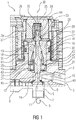
- FIG. 1 shows a schematic partial representation of a pump 1 for conveying a fluid.
- the pump 1 can be designed, for example, in the form of a fuel pump, in particular in the form of a high-pressure pump for fuel.
- the pump 1 has a housing 2 into which a first channel 3 is introduced.
- the first channel 3 opens into an inlet chamber 4 and constitutes an inlet channel.
- the inlet chamber 4 is connected to a pressure chamber 5.
- the pressure chamber 5 communicates with a second channel 6, which constitutes a drainage channel.
- the first channel 3 may be connected, for example, with a prefeed pump or with a fuel tank.
- the second channel 6 may be in communication with a fuel tank or injectors.
- a pump piston 7 is guided axially displaceable.
- the pump piston 7 is forced by a drive shaft 8 to axial up and down movements.
- a sealing seat 9 is arranged on the housing 2.
- the sealing seat 9 is associated with a second sealing seat 11, which is formed on a closing member 10.
- the sealing seat 9 and the second sealing seat 11 are each formed as annular surfaces.
- the closing member 10 is located with the second sealing seat 11 within the pressure chamber 5.
- the diameter of the pressure chamber 5 tapers in the transition region in the direction of the inlet chamber 4.
- the closing member 10 is guided through the inlet chamber 4.
- the inlet chamber 4 is connected opposite to the pressure chamber 5 with a valve chamber 13.
- a guide member 14 is disposed adjacent to the inlet chamber 4.
- the guide member 14 has a central bore 15 which has a guide surface.
- the closing member 10 has a guide portion 12, which is arranged in the bore 15 and guided by the guide surface of the bore 15 axially in a central axis 30 is.
- an armature 16 is arranged in the valve chamber 13.
- the armature 16 is cylindrical and has a cylindrical outer surface 17 on a radial outer side.
- the valve chamber 13 is cylindrical and has a second guide surface 41 for the armature 16.
- the armature 16 is formed of a magnetic material and arranged to be movable axially along the center axis 30 in the valve space 13.
- the armature 16 has a second bore 18, through which a portion 19 of the closing member 10 is guided.
- the portion 19 of the closing member 10 protrudes with an end piece 44 in the direction opposite to the pressure chamber 5 direction over the armature 16 also.
- the second bore 18 of the armature 16 is connected to at least one further channel 20 of the armature 16 in connection, wherein the further channel is guided from a bottom 43 of the armature to the second bore 18.
- the guide member 14 has an additional channel 21 which is guided from a top 42 of the guide member 14 to a bottom 45 of the guide member 14.
- the additional channel connects the inlet chamber 4 with the other channel 21 of the armature 16. In this way, a hydraulic connection between the inlet chamber 4 and the second bore 18 is made.
- the valve chamber 13 is closed with a housing cover 24, wherein in the housing cover 24 a receiving opening 25 is formed, into which the end piece 44 of the closing member 10 protrudes.
- the closing member 10 has opposite to the second sealing seat 11 on the end piece 44 outside of the armature 16 on a socket 23 which is formed as a separate component and is fixedly connected to the closing member 10.
- a spring 28 is arranged, which is clamped between the housing cover 24 and the sleeve 23.
- the bushing 23 has a first contact surface 26, which is assigned to a second contact surface 27 of the armature 16.
- the second contact surface 27 is formed adjacent to the bore 16 on an upper side of the armature 16.
- the first contact surface 26 rests with a bearing surface on the second contact surface 27.
- the first and the second contact surface 26,27 are rotationally symmetrical to the center axis 30 and have in the plane of the center axis on a radius of curvature that can vary.
- the contact surfaces 26,27 in the form of part spherical surfaces.
- the valve chamber 13 is surrounded by a magnetic coil 29, which constitutes an actuator for actuating the closing member 10 together with the armature 16.
- the actuator and the closing member form an electromagnetic valve 31.
- the spring 28 biases the closing member 10 in abutment against the armature 16, wherein the first contact surface 26 of the sleeve 23 rests on the second contact surface 27 of the armature 16 with a bearing surface.
- the inlet chamber 4 is connected to the pressure chamber 5, that is, the valve 31 is in an open position.
- the pump 1 by a movement of the pump piston 7 to suck down fluid, in particular fuel via the first channel 3.
- the valve 31 is closed by a corresponding energization of the solenoid 29 for a compression process, ie that the closing member 10 is brought to the second sealing seat 11 in contact with the sealing seat 9 of the housing 2.
- the armature 16 By the energization of the solenoid 29, the armature 16 is moved upwards, ie away from the sealing seat 9. In this case, the armature 16 presses the second contact surface 27 against the first contact surface 26 of the sleeve 23 and thus the closing member 10 upwards. Since fuel is guided via the bores in the guide part 14 and in the armature 16 between the contact surfaces 26, 27, a hydraulic fluid film is present between the contact surfaces 26, 27. This is not completely displaced upwards even with a movement of the armature and a consequent movement of the sleeve 23 and the closing member 10 upwards.
- FIG. 2 shows in a schematic representation of the armature 16 and the sleeve 23.
- the other parts of the pump, in particular the closing member 10 are not shown for simplicity.
- the first and the second contact surface 26, 27 in the form of a convex and a concave spherical surface, ie a ball-and-socket joint, the mechanical abrasion of the contact surfaces, ie the wear, is reduced. This is achieved on the one hand by the fact that even with a misalignment of the axial alignment of the bushing 23 with respect to the center axis of the shaft 30, a large contact surface between the contact surfaces 26, 27 is nevertheless present.
- the partial damping ball surfaces of the contact surfaces 26, 27 also improve the hydraulic damping pad.
- the formation of the hydraulic damping pad is supported.
- FIG. 2 shows a misalignment of the socket 23rd of 3 degrees of angle with respect to the center axis 30 and the armature 16. Due to the shape of the part ball surfaces, the contact surfaces are better at each other despite the misalignment.
- the average distance between the contact surfaces 26, 27 is relatively small. Between the contact surfaces 26,27 liquid collects, in particular at the end of the armature movement, ie causes the impact of the second sealing seat 11 on the first sealing seat 9, an advantageous hydraulic damping. This reduces the wear on the contact surfaces between the armature and the bushing.
- FIG. 2 are clearly the second bore 18 and the other channels 20 can be seen.
- additional channels 32 are provided, which are guided from a bottom to an upper side of the armature 16. As a result, a fluid exchange between the inlet chamber 4 and the receiving opening 25 is improved.
- FIG. 3 shows in an enlarged schematic representation of a section of the sleeve 23 and the armature 16 with the first and the second contact surface 26, 27.
- the armature 16 has a concave second contact surface 27 in the form of an annular part spherical surface.
- the bushing 23 has a first contact surface 26 in the form of a convex annular part spherical surface.
- the first and second contact surfaces each have a constant radius, wherein the first radius R1 of the first contact surface 26 is smaller than the second radius R2 of the second contact surface 27.
- the radii of the part spherical surfaces of the first and the second contact surface 26, 27 also be the same size.
- the armature 16 may also have the convex partial spherical surface and the sleeve 23 the concave partial spherical surface as the contact surface.
- the closing member may be integrally formed and have a corresponding contact surface.
- a center M1 of the first part spherical surface of the first contact surface 26 is laterally offset from the center axis 30.
- the lateral offset may, for example, be in the range of 10% of the radius and more.
- the lateral offset may be from 1% to 5% of the radius.
- the part of ball surfaces of the first and the second contact surface 26,27 are in the execution of FIG. 3 formed and arranged in such a way that the contact surfaces 26,27 in a central region 46 of the second contact surface 27 in the form of a circumferential annular surface touch.
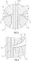
- FIG. 4 shows a schematic representation of a partial section of a further embodiment in which both the first contact surface 26 of the sleeve 23 and the second contact surface 27 of the armature 16 represent a convex part spherical surface.
- the radii are relatively large and can be in the range of meters.
- the Forming two convex contact surfaces provides an improvement in terms of abrasion compared to a formation of plane-parallel contact surfaces.
- a misalignment of the bush and / or of the armature relative to the axis 30 leads to a smaller reduction of the actual contact surface compared to plane-parallel contact surfaces.
- a better hydraulic damping pad between the contact surfaces can be formed by the convex formation of the contact surfaces.
- first and the second contact surface 26, 27 may have, in addition to the shape of the part spherical surface, further contours and / or recesses which support the formation of the damping pad.
- FIG. 5 shows in a schematic partial representation of a representation of a first and a second contact surface 26,27, wherein the contact surfaces represent rotationally symmetrical partial spherical surfaces with respect to the central axis 30, but the radius of the Operakugelober vom 26,27 is not constant, but depending on the distance to the center axis 30 varies.
- the different radii, R1, R2, R3, R4 are shown schematically in the figure. A transition between the different radii takes place continuously.
Landscapes
- Engineering & Computer Science (AREA)
- General Engineering & Computer Science (AREA)
- Mechanical Engineering (AREA)
- Chemical & Material Sciences (AREA)
- Combustion & Propulsion (AREA)
- Physics & Mathematics (AREA)
- Electromagnetism (AREA)
- Fuel-Injection Apparatus (AREA)
- Magnetically Actuated Valves (AREA)
- Details Of Reciprocating Pumps (AREA)
Description
Die Erfindung betrifft ein Ventil für eine Pumpe gemäß Patentanspruch 1 und eine Pumpe zum Fördern von Kraftstoff gemäß Patentanspruch 12.The invention relates to a valve for a pump according to claim 1 and a pump for conveying fuel according to
Aus dem Stand der Technik ist beispielsweise aus
Aus
Aus
Die Druckschrift
Aus
Aus
Aus
Aus
Aus
Aus
Die Aufgabe der Erfindung besteht darin, ein verbessertes Ventil und eine verbesserte Pumpe bereitzustellen, wobei insbesondere ein Verschleiß der Kontaktflächen zwischen dem Aktor und dem Schließkörper reduziert ist.The object of the invention is to provide an improved valve and an improved pump, wherein in particular a wear of the contact surfaces between the actuator and the closing body is reduced.
Die Aufgabe der Erfindung wird durch das Ventil gemäß Patentanspruch 1 und durch die Pumpe gemäß Patentanspruch 12 gelöst.The object of the invention is achieved by the valve according to claim 1 and by the pump according to
Weitere vorteilhafte Ausführungsformen sind in den abhängigen Ansprüchen gekennzeichnet.Further advantageous embodiments are characterized in the dependent claims.
In der erfindungsgemäßen Ausführungsform ist der Aktor in Form einer Magnetspule und eines magnetischen Ankers ausgebildet, wobei am Anker die Kontaktfläche des Aktors ausgebildet ist. Durch die Verwendung eines Ankers als Teil des Aktors wird ein einfacher, im Bauraum optimierter Aktor ermöglicht. Zudem weist der Anker eine Ausnehmung auf, durch die das Schließglied geführt ist. Die Kontaktfläche des Ankers ist angrenzend an die Ausnehmung ausgebildet.In the embodiment according to the invention, the actuator is designed in the form of a magnetic coil and a magnetic armature, the contact surface of the actuator being formed on the armature. By using an armature as part of the actuator, a simple, optimized in the space actuator is possible. In addition, the armature has a recess through which the closing member is guided. The contact surface of the armature is formed adjacent to the recess.
Ein Vorteil des beschriebenen Ventils besteht darin, dass der Abrieb der Kontaktflächen des Schließgliedes und des Aktors reduziert ist. Dies wird dadurch erreicht, dass die Kontaktflächen des Schließglieds und des Aktors in Form einer Teilkugeloberfläche ausgebildet ist. Durch die Ausbildung als Teilkugeloberfläche ist ein geringerer Abrieb gegeben. Durch die Ausbildung wenigstens einer der Kontaktflächen in Form einer Teilkugeloberfläche ist der Abrieb auch bei einer axialen Schrägstellung des Schließgliedes gegenüber dem Aktor gering. Zudem ist die tatsächliche Auflagefläche auch bei einer Schrägstellung noch relativ groß. Die Teilkugeloberfläche kann jede Art von Krümmung aufweisen, insbesondere kann der Krümmungsradius variieren.An advantage of the described valve is that the abrasion of the contact surfaces of the closing member and the actuator is reduced. This is achieved in that the contact surfaces of the closing member and the actuator is formed in the form of a part spherical surface. Due to the design as part spherical surface a lesser abrasion is given. By forming at least one of the contact surfaces in the form of a part spherical surface of the abrasion is low even with an axial inclination of the closing member relative to the actuator. In addition, the actual contact surface is still relatively large even with an inclination. The partial spherical surface may have any type of curvature, in particular the radius of curvature may vary.
Da die Kontaktflächen als Teilkugeloberflächen ausgebildet Sind, wird die tatsächliche Auflagefläche erhöht, so dass der Abrieb weiter reduziert ist. Zudem wird auch der negative Einfluss einer axialen Schrägstellung auf die tatsächliche Auflagefläche und damit der Abrieb weiter reduziert.Since the contact surfaces are formed as part spherical surfaces, the actual contact surface is increased, so that the abrasion is further reduced. In addition, the negative influence of an axial skew on the actual bearing surface and thus the abrasion is further reduced.
Die Verwendung der Buchse ermöglicht eine einfache und kostengünstige Herstellung der Kontaktfläche, da die Kontaktfläche an der Buchse vor der Befestigung der Buchse am Schließglied hergestellt wird. Die Herstellung der Kontaktfläche an einem einteiligen Schließglied ist deutlich aufwendiger und somit teurer. Zudem kann für die Ausbildung der Buchse ein anderes, insbesondere ein Material mit einer härteren Oberflächenbeschichtung als für die Ausbildung des Schließglieds verwendet werden. Durch die zweiteilige Ausbildung des Schließgliedes ist eine erhöhte Flexibilität bei den verwendeten Herstellungsprozessen und bei den verwendeten Materialien möglich.The use of the socket allows a simple and inexpensive production of the contact surface, since the contact surface is made on the socket before attaching the socket to the closing member. The production of the contact surface on a one-piece closing member is significantly more expensive and therefore more expensive. In addition, for the formation of the bushing another, in particular a material with a harder surface coating than for the formation of the closing member can be used. Due to the two-part design of the closing member increased flexibility in the manufacturing processes used and in the materials used is possible.
In einer weiteren Ausführungsform weist wenigstens eine Kontaktfläche die Form eines Teils einer Kugeloberfläche mit einem konstanten Radius auf. Durch die Ausbildung der Kontaktflächen in Form von Kugeloberflächen ist der Abrieb bei einer axialen Schrägstellung des Schließgliedes gegenüber dem Aktor weiter reduziert. Zudem ist die Ausbildung der Kugeloberfläche mit einem konstanten Radius relativ einfach und kostengünstig auszuführen.In a further embodiment, at least one contact surface has the shape of a part of a spherical surface with a constant radius. Due to the formation of the contact surfaces in the form of spherical surfaces of the abrasion at a axial inclination of the closing member relative to the actuator further reduced. In addition, the formation of the spherical surface with a constant radius is relatively easy and inexpensive to perform.
In einer weiteren Ausführungsform sind beide Kontaktflächen als Teil einer Kugeloberfläche mit jeweils konstantem Radius ausgebildet. Durch die Ausbildung der Kugeloberflächen als Kugeloberflächen mit konstantem Radius ist der Abrieb an den Kontaktflächen gering, auch wenn der Aktor und/oder das Schließglied in der axialen Ausrichtung nicht präzise parallel zueinander ausgerichtet sind.In a further embodiment, both contact surfaces are formed as part of a spherical surface, each with a constant radius. Due to the design of the spherical surfaces as spherical surfaces with a constant radius of abrasion at the contact surfaces is low, even if the actuator and / or the closing member in the axial alignment are not precisely aligned parallel to each other.
In einer weiteren Ausführungsform sind beide Kontaktflächen als Teil einer konvexen Kugeloberfläche ausgebildet. Auf diese Weise kann eine Reduzierung des Abriebes bei geringen Anforderungen an die Genauigkeit der Kugeloberflächen erreicht werden.In a further embodiment, both contact surfaces are formed as part of a convex spherical surface. In this way, a reduction of the abrasion can be achieved with low demands on the accuracy of the spherical surfaces.
In einer weiteren Ausführungsform liegen die Radien im Bereich von Metern. Durch die großen Radien wird insbesondere bei der Ausbildung von zwei konvexen Kontaktflächen, insbesondere bei konvexen Kugeloberflächen eine große Auflagefläche erreicht und trotzdem bei einer Verkippung zwischen den Kontaktflächen eine große Auflagefläche und damit ein geringer Abrieb erreicht.In a further embodiment, the radii are in the range of meters. Due to the large radii, a large bearing surface is achieved, in particular in the case of the formation of two convex contact surfaces, in particular in the case of convex spherical surfaces, and nevertheless a large contact surface and thus a low abrasion is achieved with a tilt between the contact surfaces.
In einer weiteren Ausführungsform weisen die Kugeloberflächen der zwei Kontaktflächen unterschiedliche Radien auf. Dies ist insbesondere bei der Ausbildung einer konvex-konkaven Anordnung der Kontaktflächen von Vorteil. Bei der Verwendung eines größeren Radius für die konvex ausgebildete Kugeloberfläche und der Verwendung eines kleineren Radius für die konkav ausgebildete Kugeloberfläche kann eine große Auflagefläche auch bei einer axialen Schrägstellung der zwei Kontaktflächen ohne ein Verspannen erreicht werden.In a further embodiment, the spherical surfaces of the two contact surfaces have different radii. This is particularly advantageous in the formation of a convex-concave arrangement of the contact surfaces. When using a larger radius for the convex spherical surface and the use of a smaller radius for the concave spherical surface, a large contact surface can be achieved even with an axial inclination of the two contact surfaces without jamming.
In einer Ausführungsform ist eine Kontaktfläche wenigstens teilweise konvex und die andere Kontaktfläche wenigstens teilweise konkav ausgebildet. Durch die Paarung einer konvexen Kugeloberfläche mit einer konkaven Kugeloberfläche wird eine große Auflagefläche zwischen dem Aktor und dem Schließglied bereitgestellt, die auch bei einem Verkippen des Aktors gegenüber dem Schließglied eine große Auflagefläche ermöglicht. Somit ist der Abrieb reduziert.In one embodiment, one contact surface is at least partially convex and the other contact surface is at least partially concave. By pairing a convex spherical surface with a concave spherical surface, a large contact surface between the actuator and the closing member is provided, which allows for a tilting of the actuator relative to the closing member a large contact surface. Thus, the abrasion is reduced.
Weiterhin kommt es bei der Betätigung des Ventils zu Situationen, in denen ein Spalt zwischen den Kontaktflächen des Aktors und des Schließglieds vorliegt. In dieser Situation führt die Form der Kugeloberflächen insbesondere in der Paarung konvex-konkav dazu, dass das Aufeinanderschlagen der Kontaktflächen hydraulisch gedämpft ist, da der Raum zwischen den Kontaktflächen mit Fluid, insbesondere mit Kraftstoff gefüllt ist. Somit kann neben der großen Auflagefläche auch bei einer axialen Verkippung zusätzlich noch eine hydraulische Dämpfung durch das Fluid erreicht werden.Furthermore, it comes in the operation of the valve to situations in which there is a gap between the contact surfaces of the actuator and the closing member. In this situation, the shape of the spherical surfaces, in particular in the pairing convex-concave, results in that the impacting of the contact surfaces is hydraulically damped, since the space between the contact surfaces is filled with fluid, in particular with fuel. Thus, in addition to the large contact surface even with an axial tilting additionally a hydraulic damping can be achieved by the fluid.
In einer weiteren Ausführungsform sind die Krümmungen, insbesondere die Radien der konvexen und der konkaven Kontaktfläche in der Weise gewählt, dass eine ringförmige Auflagefläche zwischen der konvexen und der konkaven Kontaktfläche in einer Mitte der ringförmigen konkaven Kontaktfläche, insbesondere der konkaven Teilkugeloberfläche ausgebildet ist. Dadurch wird eine möglichst große Auflagefläche auch bei einer axialen Schrägstellung des Schließgliedes erreicht. Zudem wird die Ausbildung des hydraulischen Dämpfungspolsters unterstützt.In a further embodiment, the curvatures, in particular the radii of the convex and the concave contact surface, are selected in such a way that an annular bearing surface is formed between the convex and the concave contact surface in a center of the annular concave contact surface, in particular the concave partial spherical surface. As a result, the largest possible contact surface is achieved even with an axial inclination of the closing member. In addition, the formation of the hydraulic damping pad is supported.
In einer weiteren Ausführungsform sind die Kontaktflächen als Teilkugelflächen ausgebildet, wobei die Mittelachsen der Teilkugelflächen seitlich versetzt angeordnet sind. Dadurch wird eine seitliche Fehlstellung erreicht, die zu einem etwas vergrößerten Spalt zwischen den Kontaktflächen führt. Der vergrößerte Spalt unterstützt die Ausbildung des fluiden Dämpfungspolsters zwischen den Kontaktflächen.In a further embodiment, the contact surfaces are formed as partial spherical surfaces, wherein the central axes of the partial spherical surfaces are arranged offset laterally. As a result, a lateral misalignment is achieved, which leads to a slightly larger gap between the contact surfaces. The enlarged gap assists the formation of the fluid damping pad between the contact surfaces.
In einer weiteren Ausführungsform weist das Schließglied einen Abschnitt mit einer Führungsfläche auf, wobei das Schließglied mit dem Abschnitt axial im Ventilgehäuse geführt ist, und wobei der Anker wenigstens einen weiteren Kanal aufweist, wobei der weitere Kanal in die Ausnehmung mündet und zum Zuführen von Fluid von dem Kanal in den Bereich der Kontaktflächen vorgesehen ist.In a further embodiment, the closing member has a portion with a guide surface, wherein the closing member is axially guided in the valve housing with the portion, and wherein the armature has at least one further channel, wherein the further channel opens into the recess and for supplying fluid from the channel is provided in the region of the contact surfaces.
In einer weiteren Ausführungsform weist das Ventilgehäuse einen weiteren Kanal auf, über den Fluid, insbesondere Kraftstoff in den Bereich der Kontaktflächen geführt wird. Dies führt dazu, dass die Ausbildung des hydraulischen Dämpfungspolsters, das durch das Fluid zwischen den Kontaktflächen gebildet wird, unterstützt wird. Im Kanal des Ventilgehäuses herrscht ein ausreichender Druck, der für die Bildung des hydraulischen Polsters sorgt.In a further embodiment, the valve housing has a further channel, via which fluid, in particular fuel, is guided into the region of the contact surfaces. As a result, the formation of the hydraulic damping pad formed by the fluid between the contact surfaces is promoted. In the channel of the valve body there is a sufficient pressure, which ensures the formation of the hydraulic pad.
Die Erfindung wird im Folgenden anhand der Figuren näher erläutert. Es zeigen:
-
Figur 1 einen schematischen Teilausschnitt einer Pumpe für Kraftstoff, -
Figur 2 -
Figur 3 -
Figur 4 eine schematische Darstellung einer Ausführungsform mit zwei konvexen Kontaktflächen, und -
Figur 5
-
FIG. 1 a schematic partial section of a pump for fuel, -
FIG. 2 a schematic representation of the armature and a socket of the closing member, -
FIG. 3 an enlarged schematic representation of the contact surfaces of the closing member and the armature, -
FIG. 4 a schematic representation of an embodiment with two convex contact surfaces, and -
FIG. 5 a schematic representation of another embodiment with contact surfaces whose part spherical surfaces have a plurality of radii.
Der Ventilraum 13 ist mit einem Gehäusedeckel 24 verschlossen, wobei im Gehäusedeckel 24 eine Aufnahmeöffnung 25 ausgebildet, in die das Endstück 44 des Schließgliedes 10 ragt. Das Schließglied 10 weist gegenüberliegend zum zweiten Dichtsitz 11 an dem Endstück 44 außerhalb des Ankers 16 eine Buchse 23 auf, die als separates Bauteil ausgebildet ist und fest mit dem Schließglied 10 verbunden ist. In der Aufnahmeöffnung 25 ist eine Feder 28 angeordnet, die zwischen dem Gehäusedeckel 24 und der Buchse 23 eingespannt ist. Die Buchse 23 weist eine erste Kontaktfläche 26 auf, die einer zweiten Kontaktfläche 27 des Ankers 16 zugeordnet ist. Die zweite Kontaktfläche 27 ist angrenzend an die Bohrung 16 auf einer Oberseite des Ankers 16 ausgebildet.The
In bestimmten Situationen liegt die erste Kontaktfläche 26 mit einer Auflagefläche auf der zweiten Kontaktfläche 27 auf. Die erste und die zweite Kontaktfläche 26,27 sind rotationssymmetrisch zu der Mittenachse 30 ausgebildet und weisen in der Ebene der Mittenachse einen Krümmungsradius auf, der variieren kann. Somit weisen die Kontaktflächen 26,27 die Form von Teilkugeloberflächen auf. Der Ventilraum 13 ist von einer Magnetspule 29 umgeben, die zusammen mit dem Anker 16 einen Aktor zur Betätigung des Schließglieds 10 darstellt. Der Aktor und das Schließglied bilden ein elektromagentisches Ventil 31.In certain situations, the
In der dargestellten Situation spannt die Feder 28 das Schließglied 10 in Anlage auf den Anker 16 vor, wobei die erste Kontaktfläche 26 der Buchse 23 auf der zweiten Kontaktfläche 27 des Ankers 16 mit einer Auflagefläche aufliegt. Dabei ist die Zulaufkammer 4 mit der Druckkammer 5 verbunden, d. h. das Ventil 31 ist in einer offenen Position. In der offenen Position des Ventils 31 kann die Pumpe 1 durch eine Bewegung des Pumpkolbens 7 nach unten Fluid, insbesondere Kraftstoff über den ersten Kanal 3 ansaugen. Nach dem Ansaugen wird für einen Verdichtungsvorgang das Ventil 31 durch eine entsprechende Bestromung der Magnetspule 29 geschlossen wird, d. h. dass das Schließglied 10 mit dem zweiten Dichtsitz 11 in Anlage an den Dichtsitz 9 des Gehäuses 2 gebracht wird. Durch die Bestromung der Magnetspule 29 wird der Anker 16 nach oben, d. h. weg von dem Dichtsitz 9, bewegt. Dabei drückt der Anker 16 die zweite Kontaktfläche 27 an die erste Kontaktfläche 26 der Buchse 23 und damit das Schließglied 10 nach oben. Da Kraftstoff über die Bohrungen im Führungsteil 14 und im Anker 16 zwischen die Kontaktflächen 26, 27 geführt ist, ist zwischen den Kontaktflächen 26, 27 ein hydraulischer Fluidfilm vorhanden. Dieser wird auch bei einer Bewegung des Ankers nach oben und einer daraus folgenden Bewegung der Buchse 23 und des Schließglieds 10 nach oben nicht vollständig verdrängt. Erst bei einem Auftreffen des zweiten Dichtsitzes 11 auf den Dichtsitz 9 wird der Anker 16 stärker gegen die Buchse 23 gedrückt, so dass der Fluidfilm aus dem Bereich zwischen den Kontaktflächen 26, 27 vollständig verdrängt wird. Dadurch wird eine hydraulische Dämpfung des Aufschlagens der zweiten Kontaktfläche 27 auf die erste Kontaktfläche 26 abgeschwächt. Bei einem geschlossenen Ventil 31 wird durch eine Bewegung des Pumpkolbens 7 nach oben Kraftstoff mit einem erhöhten Druck in den zweiten Kanal 6 befördert. Der zweite Kanal 6 kann ein Rückschlagventil aufweisen, das einen Rückfluss von Fluid aus dem zweiten Kanal 6 in die Druckkammer 5 verhindert.In the illustrated situation, the
Für ein Öffnen des Ventils 31 ist es ausreichend, den Strom durch die Magnetspule abzustellen. Beim Schließen des Ventils 31 wurde die Feder 28 zusammengedrückt. Bei fehlender Magnetkraft entspannt sich die Feder 28, wobei das Schließglied 10 nach unten bewegt wird und der zweite Dichtsitz 11 vom Dichtsitz 9 abgehoben wird. Damit wird das Ventil 31 geöffnet, so dass eine hydraulische Verbindung zwischen der Druckkammer 5 und dem ersten Kanal 3 besteht.For opening the
In
Abhängig von der gewählten Ausführungsform kann auch der Anker 16 die konvexe Teilkugeloberfläche und die Buchse 23 die konkave Teilkugeloberfläche als Kontaktfläche aufweisen. Zudem kann anstelle der separaten Buchse 23 auch das Schließglied einteilig ausgebildet sein und eine entsprechende Kontaktfläche aufweisen.Depending on the chosen embodiment, the
In der dargestellten Ausführungsform ist ein Mittelpunkt M2 der Teilkugeloberfläche der zweiten Kontaktfläche 27 auf der Mittenachse 30. Ein Mittelpunkt M1 der ersten Teilkugeloberfläche der ersten Kontaktfläche 26 ist seitlich versetzt zur Mittenachse 30 angeordnet. Durch die seitliche Versetzung der Mittelpunkte der Teilkugeloberflächen wird eine leichte Fehlpassung erzeugt, wodurch die Ausbildung des fluiden Dämpfungspolsters unterstützt wird. Die seitliche Versetzung kann beispielsweise im Bereich von 10 % des Radius und mehr liegen. Weiterhin kann die seitliche Versetzung bei 1% bis 5% des Radius liegen. Die Teilkugeloberflächen der ersten und der zweiten Kontaktfläche 26,27 sind in der Ausführung der
Abhängig von der gewählten Ausführungsform können die erste und die zweite Kontaktfläche 26, 27 zusätzlich zu der Form der Teilkugeloberfläche noch weitere Konturen und/oder Ausnehmungen aufweisen, die die Ausbildung des Dämpfungspolsters unterstützen.Depending on the chosen embodiment, the first and the
Claims (11)
- Valve (31) for a pump (1) for delivering fuel, with a housing (2) and with a closing element (10), wherein the closing element (10) is guided moveably along an axis (30) in the housing (2), wherein the closing element (10) is configured to close a channel (3) of the pump (1), wherein an actuator (16, 29) is provided, wherein the closing element (10) has a first contact face (26), wherein the actuator (16, 29) has a second contact face (27), wherein the closing element (10) and the actuator (16, 29) are actively connected to each other via the contact faces (26, 27), wherein the actuator is configured as a magnetic coil (29) and a magnetic rotor (16), and wherein the second contact face (27) is formed on the rotor (16), wherein the rotor (16) has a recess (18) through which the closing element (10) is guided, and wherein the second contact face (27) is formed on the rotor (16) adjacent to the recess (18), characterized in that the two contact faces (26, 27) are configured as a spherical surface portion and a separate bush (23) is attached to the closing element (10) and the first contact face (26) is formed on the bush (23).
- Valve according to Claim 1, wherein at least one spherical surface portion has a constant radius.
- Valve according to either of the preceding claims, wherein the contact face is formed as part of a convex spherical surface.
- Valve according to either of Claims 1 and 2, wherein one contact face is formed as part of a convex spherical surface and the other contact face is formed as part of a concave spherical surface.
- Valve according to Claim 4, wherein the concave spherical surface has a larger radius than the convex
spherical surface, wherein the contact faces are formed as an annular part of a spherical surface and wherein preferably an annular contact line (45) is present between the convex and the concave contact faces in a middle of a width of the annular concave semi-spherical surface (26, 27). - Valve according to Claim 5, wherein the differences in the radii are up to 20%, in particular up to 15%, preferably up to 5%.
- Valve according to any of Claims 4 to 6, wherein the semi-spherical surfaces (26, 27) are formed and arranged such that the center points (M1, M2) of the semi-spherical surfaces are arranged laterally offset.
- Valve according to any of the preceding claims, wherein the radii of the spherical surfaces are in the meter range.
- Valve according to any of Claims 1 to 8, wherein the closing element (10) has a guide portion (12) with a guide surface, wherein the closing element (10) is axially guided with the guide portion in the housing (2), and wherein the rotor (16) has at least one channel (20), wherein the channel (20) opens into the recess (18) and is provided for supplying fluid from the channel (3) into the region of the contact faces (26, 27).
- Valve according to Claim 9, wherein the housing (2, 14) has a guide part (14), wherein the closing element (10) is guided in the guide part (14), wherein the guide
part (14) has a further channel (21) which is connected at one end to the channel (3) of the housing (2) and at the other end to the channel (20) of the rotor (16). - Pump (1) for delivering fuel to an engine of a vehicle with a valve according to any of the preceding claims.
Applications Claiming Priority (2)
| Application Number | Priority Date | Filing Date | Title |
|---|---|---|---|
| DE102012218593.3A DE102012218593A1 (en) | 2012-10-12 | 2012-10-12 | Valve for a pump |
| PCT/EP2013/071211 WO2014057060A1 (en) | 2012-10-12 | 2013-10-10 | Valve for a pump |
Publications (2)
| Publication Number | Publication Date |
|---|---|
| EP2906815A1 EP2906815A1 (en) | 2015-08-19 |
| EP2906815B1 true EP2906815B1 (en) | 2019-06-19 |
Family
ID=49552321
Family Applications (1)
| Application Number | Title | Priority Date | Filing Date |
|---|---|---|---|
| EP13788688.3A Active EP2906815B1 (en) | 2012-10-12 | 2013-10-10 | Valve for a pump |
Country Status (7)
| Country | Link |
|---|---|
| US (1) | US9528484B2 (en) |
| EP (1) | EP2906815B1 (en) |
| JP (1) | JP6141436B2 (en) |
| KR (1) | KR102087469B1 (en) |
| CN (1) | CN104685203B (en) |
| DE (1) | DE102012218593A1 (en) |
| WO (1) | WO2014057060A1 (en) |
Families Citing this family (15)
| Publication number | Priority date | Publication date | Assignee | Title |
|---|---|---|---|---|
| DE102012218593A1 (en) | 2012-10-12 | 2014-04-17 | Continental Automotive Gmbh | Valve for a pump |
| DE102014200695A1 (en) * | 2014-01-16 | 2015-07-16 | Robert Bosch Gmbh | High pressure pump with an electromagnetic suction valve |
| DE102014215774B4 (en) | 2014-08-08 | 2016-06-30 | Continental Automotive Gmbh | Device for a high-pressure pump for a motor vehicle |
| DE102014220975A1 (en) * | 2014-10-16 | 2016-04-21 | Robert Bosch Gmbh | Electromagnetically actuated inlet valve and high-pressure pump with inlet valve |
| GB201502693D0 (en) * | 2015-02-18 | 2015-04-01 | Delphi International Operations Luxembourg S.�.R.L. | Actuator assembly of a digital inlet valve |
| JP6530978B2 (en) * | 2015-06-29 | 2019-06-12 | 日立オートモティブシステムズ株式会社 | Solenoid valve and high pressure fuel supply pump |
| DE102015212376A1 (en) | 2015-07-02 | 2017-01-05 | Robert Bosch Gmbh | Electromagnetically operated suction valve for a high-pressure pump and high-pressure pump |
| DE102015218054A1 (en) * | 2015-09-21 | 2017-03-23 | Robert Bosch Gmbh | Valve, in particular suction valve, in a high-pressure pump of a fuel injection system |
| DE102015224421A1 (en) * | 2015-12-07 | 2017-06-08 | Robert Bosch Gmbh | Electromagnetically actuated inlet valve and high-pressure pump with inlet valve |
| KR101808924B1 (en) * | 2015-12-17 | 2017-12-13 | 주식회사 현대케피코 | Solenoid Valve With Improved Noise and Lubricating Structure |
| DE102017214351A1 (en) * | 2017-08-17 | 2019-02-21 | Continental Teves Ag & Co. Ohg | Proportional control valve |
| JP6838244B2 (en) * | 2019-05-17 | 2021-03-03 | 日立Astemo株式会社 | Solenoid valve and high pressure fuel supply pump |
| CN117255893A (en) * | 2021-05-04 | 2023-12-19 | 康明斯有限公司 | Pump assembly with barrel guidance feature |
| GB2607613B (en) * | 2021-06-09 | 2023-10-18 | Delphi Tech Ip Ltd | Valve assembly for a fuel pump |
| DE102021128649A1 (en) * | 2021-11-03 | 2023-05-04 | Agilent Technologies, Inc. | Rotary valve with compensating element to compensate for an axial offset |
Citations (2)
| Publication number | Priority date | Publication date | Assignee | Title |
|---|---|---|---|---|
| US4597558A (en) * | 1984-07-26 | 1986-07-01 | Robert Bosch Gmbh | Electromagnetically actuatable valve |
| EP1657435A1 (en) * | 2004-11-12 | 2006-05-17 | C.R.F. Società Consortile per Azioni | A fuel injector for an internal-combustion engine |
Family Cites Families (24)
| Publication number | Priority date | Publication date | Assignee | Title |
|---|---|---|---|---|
| US2935995A (en) * | 1959-06-09 | 1960-05-10 | Lee Beckham | Reversible valve assembly for pumps |
| DE2052307A1 (en) * | 1970-10-24 | 1972-05-25 | Teves Gmbh Alfred | Electromagnetically operated seat valve |
| DE2208183A1 (en) | 1972-02-22 | 1973-08-30 | Bosch Gmbh Robert | MAGNETIC VALVE |
| DE7335302U (en) * | 1973-09-29 | 1974-04-25 | Ges Fuer Kernforschung Mbh | PLUGLESS SOLENOID VALVE FOR AGGRESSIVE MEDIA |
| DE3507443A1 (en) * | 1985-03-02 | 1986-09-04 | Robert Bosch Gmbh, 7000 Stuttgart | ELECTROMAGNETICALLY ACTUABLE FUEL INJECTION VALVE |
| DE3521040A1 (en) * | 1985-06-12 | 1986-12-18 | Vdo Adolf Schindling Ag, 6000 Frankfurt | INJECTION VALVE |
| JPS62151481A (en) | 1985-12-26 | 1987-07-06 | Sunstar Giken Kk | Hot-melt adhesive |
| JPS62151481U (en) * | 1986-03-18 | 1987-09-25 | ||
| DE3641470A1 (en) * | 1986-12-04 | 1988-06-16 | Bosch Gmbh Robert | ELECTROMAGNETICALLY ACTUABLE FUEL INJECTION VALVE |
| DE4142998C1 (en) * | 1991-12-24 | 1993-07-22 | Robert Bosch Gmbh, 7000 Stuttgart, De | |
| DE4243665C2 (en) | 1992-12-23 | 2003-11-13 | Bosch Gmbh Robert | Fuel injection device, in particular pump nozzle for internal combustion engines |
| US5954487A (en) | 1995-06-23 | 1999-09-21 | Diesel Technology Company | Fuel pump control valve assembly |
| DE19700979A1 (en) | 1997-01-14 | 1998-07-16 | Teves Gmbh Alfred | magnetic valve |
| DE19757659C1 (en) * | 1997-12-23 | 1999-06-17 | Siemens Ag | Fuel injection valve with compensation surface e.g. for motor vehicle IC engine |
| DE19917756A1 (en) * | 1998-07-06 | 2000-01-13 | Continental Teves Ag & Co Ohg | Solenoid valve, especially for slip-controlled car brake installations |
| JP2003120468A (en) | 2001-10-15 | 2003-04-23 | Bosch Automotive Systems Corp | Fuel liquid flow control valve, and fuel injection system for an internal combustion engine provided with the fuel liquid flow control valve |
| DE10255740A1 (en) | 2002-11-28 | 2004-06-09 | Bosch Rexroth Ag | Direct operated prop. Pressure relief valve |
| DE10332345A1 (en) * | 2003-02-05 | 2004-08-19 | Continental Teves Ag & Co. Ohg | Solenoid valve |
| US7857282B2 (en) | 2003-02-05 | 2010-12-28 | Continental Teves Ag & Co., Ohg | Solenoid valve |
| DE202004002432U1 (en) * | 2004-02-17 | 2005-07-07 | Hawe Hydraulik Gmbh & Co. Kg | Magnetic double valve |
| DE102004028968B4 (en) * | 2004-06-16 | 2006-04-27 | Karl Dungs Gmbh & Co. Kg | Valve with safe opening indication |
| DE102008018018A1 (en) | 2008-04-09 | 2009-10-15 | Continental Automotive Gmbh | Pump for conveying a fluid |
| JP5468932B2 (en) | 2010-02-19 | 2014-04-09 | 株式会社鷺宮製作所 | Solenoid control valve |
| DE102012218593A1 (en) | 2012-10-12 | 2014-04-17 | Continental Automotive Gmbh | Valve for a pump |
-
2012
- 2012-10-12 DE DE102012218593.3A patent/DE102012218593A1/en not_active Withdrawn
-
2013
- 2013-10-10 EP EP13788688.3A patent/EP2906815B1/en active Active
- 2013-10-10 US US14/427,558 patent/US9528484B2/en active Active
- 2013-10-10 KR KR1020157011993A patent/KR102087469B1/en active Active
- 2013-10-10 WO PCT/EP2013/071211 patent/WO2014057060A1/en not_active Ceased
- 2013-10-10 JP JP2015536133A patent/JP6141436B2/en active Active
- 2013-10-10 CN CN201380053190.7A patent/CN104685203B/en active Active
Patent Citations (2)
| Publication number | Priority date | Publication date | Assignee | Title |
|---|---|---|---|---|
| US4597558A (en) * | 1984-07-26 | 1986-07-01 | Robert Bosch Gmbh | Electromagnetically actuatable valve |
| EP1657435A1 (en) * | 2004-11-12 | 2006-05-17 | C.R.F. Società Consortile per Azioni | A fuel injector for an internal-combustion engine |
Also Published As
| Publication number | Publication date |
|---|---|
| WO2014057060A1 (en) | 2014-04-17 |
| JP2015532388A (en) | 2015-11-09 |
| CN104685203A (en) | 2015-06-03 |
| KR102087469B1 (en) | 2020-03-11 |
| EP2906815A1 (en) | 2015-08-19 |
| KR20150068974A (en) | 2015-06-22 |
| CN104685203B (en) | 2017-07-18 |
| US9528484B2 (en) | 2016-12-27 |
| DE102012218593A1 (en) | 2014-04-17 |
| US20150345449A1 (en) | 2015-12-03 |
| JP6141436B2 (en) | 2017-06-07 |
Similar Documents
| Publication | Publication Date | Title |
|---|---|---|
| WO2014057060A1 (en) | Valve for a pump | |
| EP2246601B1 (en) | Electromagnetic hydraulic valve | |
| AT500185A2 (en) | MECHANISM OF AN ELECTROMAGNETIC VALVE | |
| DE102017200212A1 (en) | Two-stage pump with diverter valve | |
| DE102010021395B4 (en) | solenoid valve | |
| EP2816219B1 (en) | Control valve for a fuel injector | |
| DE102014217441A1 (en) | Electromagnetically actuated proportional valve | |
| WO2011079989A1 (en) | Electromagnetically actuated volume control valve, in particular for controlling the delivery volume of a high-pressure fuel pump | |
| EP3387247B1 (en) | Electromagnetically actuatable inlet valve and high-pressure pump having an inlet valve | |
| WO2008049668A1 (en) | Injector for injecting fuel into combustion chambers of internal combustion engines | |
| DE102016214884A1 (en) | Electromagnetically operated suction valve and high-pressure fuel pump | |
| EP1891323B1 (en) | Fuel metering unit for a high-pressure fuel pump and associated high-pressure fuel pump | |
| DE102016211679A1 (en) | Electromagnetically actuated inlet valve and high-pressure pump with inlet valve | |
| EP3159535B1 (en) | Electromagnetic valve | |
| EP3935296B1 (en) | Device for regulating the flow of a fluid | |
| WO2003025441A1 (en) | Non-return valve for a pump | |
| EP2643619B1 (en) | Valve device having a movement element which is cylindrical at least in sections | |
| WO2007068389A1 (en) | Differential pressure valve | |
| EP3332111B1 (en) | Electromagnetically actuatable intake valve for a high-pressure pump, and high-pressure pump | |
| EP2016276B1 (en) | Fuel-injector with optimised return pipe | |
| DE102019218093B4 (en) | Diaphragm valve | |
| DE10132450A1 (en) | Fuel injection valve for internal combustion engines | |
| DE102015218054A1 (en) | Valve, in particular suction valve, in a high-pressure pump of a fuel injection system | |
| WO2020083550A1 (en) | Electromagnetically actuatable inlet valve and high-pressure pump having an inlet valve | |
| WO2017089032A1 (en) | Electromagnetically actuatable suction valve for a high-pressure pump, and high-pressure pump |
Legal Events
| Date | Code | Title | Description |
|---|---|---|---|
| PUAI | Public reference made under article 153(3) epc to a published international application that has entered the european phase |
Free format text: ORIGINAL CODE: 0009012 |
|
| 17P | Request for examination filed |
Effective date: 20150512 |
|
| AK | Designated contracting states |
Kind code of ref document: A1 Designated state(s): AL AT BE BG CH CY CZ DE DK EE ES FI FR GB GR HR HU IE IS IT LI LT LU LV MC MK MT NL NO PL PT RO RS SE SI SK SM TR |
|
| AX | Request for extension of the european patent |
Extension state: BA ME |
|
| DAX | Request for extension of the european patent (deleted) | ||
| STAA | Information on the status of an ep patent application or granted ep patent |
Free format text: STATUS: EXAMINATION IS IN PROGRESS |
|
| 17Q | First examination report despatched |
Effective date: 20170224 |
|
| GRAP | Despatch of communication of intention to grant a patent |
Free format text: ORIGINAL CODE: EPIDOSNIGR1 |
|
| STAA | Information on the status of an ep patent application or granted ep patent |
Free format text: STATUS: GRANT OF PATENT IS INTENDED |
|
| INTG | Intention to grant announced |
Effective date: 20190205 |
|
| GRAS | Grant fee paid |
Free format text: ORIGINAL CODE: EPIDOSNIGR3 |
|
| GRAA | (expected) grant |
Free format text: ORIGINAL CODE: 0009210 |
|
| STAA | Information on the status of an ep patent application or granted ep patent |
Free format text: STATUS: THE PATENT HAS BEEN GRANTED |
|
| AK | Designated contracting states |
Kind code of ref document: B1 Designated state(s): AL AT BE BG CH CY CZ DE DK EE ES FI FR GB GR HR HU IE IS IT LI LT LU LV MC MK MT NL NO PL PT RO RS SE SI SK SM TR |
|
| REG | Reference to a national code |
Ref country code: GB Ref legal event code: FG4D Free format text: NOT ENGLISH |
|
| REG | Reference to a national code |
Ref country code: CH Ref legal event code: EP |
|
| REG | Reference to a national code |
Ref country code: IE Ref legal event code: FG4D Free format text: LANGUAGE OF EP DOCUMENT: GERMAN |
|
| REG | Reference to a national code |
Ref country code: DE Ref legal event code: R096 Ref document number: 502013013037 Country of ref document: DE |
|
| REG | Reference to a national code |
Ref country code: AT Ref legal event code: REF Ref document number: 1145839 Country of ref document: AT Kind code of ref document: T Effective date: 20190715 |
|
| REG | Reference to a national code |
Ref country code: NL Ref legal event code: MP Effective date: 20190619 |
|
| PG25 | Lapsed in a contracting state [announced via postgrant information from national office to epo] |
Ref country code: NO Free format text: LAPSE BECAUSE OF FAILURE TO SUBMIT A TRANSLATION OF THE DESCRIPTION OR TO PAY THE FEE WITHIN THE PRESCRIBED TIME-LIMIT Effective date: 20190919 Ref country code: AL Free format text: LAPSE BECAUSE OF FAILURE TO SUBMIT A TRANSLATION OF THE DESCRIPTION OR TO PAY THE FEE WITHIN THE PRESCRIBED TIME-LIMIT Effective date: 20190619 Ref country code: FI Free format text: LAPSE BECAUSE OF FAILURE TO SUBMIT A TRANSLATION OF THE DESCRIPTION OR TO PAY THE FEE WITHIN THE PRESCRIBED TIME-LIMIT Effective date: 20190619 Ref country code: SE Free format text: LAPSE BECAUSE OF FAILURE TO SUBMIT A TRANSLATION OF THE DESCRIPTION OR TO PAY THE FEE WITHIN THE PRESCRIBED TIME-LIMIT Effective date: 20190619 Ref country code: HR Free format text: LAPSE BECAUSE OF FAILURE TO SUBMIT A TRANSLATION OF THE DESCRIPTION OR TO PAY THE FEE WITHIN THE PRESCRIBED TIME-LIMIT Effective date: 20190619 Ref country code: LT Free format text: LAPSE BECAUSE OF FAILURE TO SUBMIT A TRANSLATION OF THE DESCRIPTION OR TO PAY THE FEE WITHIN THE PRESCRIBED TIME-LIMIT Effective date: 20190619 |
|
| REG | Reference to a national code |
Ref country code: LT Ref legal event code: MG4D |
|
| PG25 | Lapsed in a contracting state [announced via postgrant information from national office to epo] |
Ref country code: GR Free format text: LAPSE BECAUSE OF FAILURE TO SUBMIT A TRANSLATION OF THE DESCRIPTION OR TO PAY THE FEE WITHIN THE PRESCRIBED TIME-LIMIT Effective date: 20190920 Ref country code: BG Free format text: LAPSE BECAUSE OF FAILURE TO SUBMIT A TRANSLATION OF THE DESCRIPTION OR TO PAY THE FEE WITHIN THE PRESCRIBED TIME-LIMIT Effective date: 20190919 Ref country code: RS Free format text: LAPSE BECAUSE OF FAILURE TO SUBMIT A TRANSLATION OF THE DESCRIPTION OR TO PAY THE FEE WITHIN THE PRESCRIBED TIME-LIMIT Effective date: 20190619 Ref country code: LV Free format text: LAPSE BECAUSE OF FAILURE TO SUBMIT A TRANSLATION OF THE DESCRIPTION OR TO PAY THE FEE WITHIN THE PRESCRIBED TIME-LIMIT Effective date: 20190619 |
|
| RAP2 | Party data changed (patent owner data changed or rights of a patent transferred) |
Owner name: CPT GROUP GMBH |
|
| RAP2 | Party data changed (patent owner data changed or rights of a patent transferred) |
Owner name: VITESCO TECHNOLOGIES GMBH |
|
| PG25 | Lapsed in a contracting state [announced via postgrant information from national office to epo] |
Ref country code: CZ Free format text: LAPSE BECAUSE OF FAILURE TO SUBMIT A TRANSLATION OF THE DESCRIPTION OR TO PAY THE FEE WITHIN THE PRESCRIBED TIME-LIMIT Effective date: 20190619 Ref country code: RO Free format text: LAPSE BECAUSE OF FAILURE TO SUBMIT A TRANSLATION OF THE DESCRIPTION OR TO PAY THE FEE WITHIN THE PRESCRIBED TIME-LIMIT Effective date: 20190619 Ref country code: EE Free format text: LAPSE BECAUSE OF FAILURE TO SUBMIT A TRANSLATION OF THE DESCRIPTION OR TO PAY THE FEE WITHIN THE PRESCRIBED TIME-LIMIT Effective date: 20190619 Ref country code: NL Free format text: LAPSE BECAUSE OF FAILURE TO SUBMIT A TRANSLATION OF THE DESCRIPTION OR TO PAY THE FEE WITHIN THE PRESCRIBED TIME-LIMIT Effective date: 20190619 Ref country code: PT Free format text: LAPSE BECAUSE OF FAILURE TO SUBMIT A TRANSLATION OF THE DESCRIPTION OR TO PAY THE FEE WITHIN THE PRESCRIBED TIME-LIMIT Effective date: 20191021 Ref country code: SK Free format text: LAPSE BECAUSE OF FAILURE TO SUBMIT A TRANSLATION OF THE DESCRIPTION OR TO PAY THE FEE WITHIN THE PRESCRIBED TIME-LIMIT Effective date: 20190619 |
|
| PG25 | Lapsed in a contracting state [announced via postgrant information from national office to epo] |
Ref country code: IT Free format text: LAPSE BECAUSE OF FAILURE TO SUBMIT A TRANSLATION OF THE DESCRIPTION OR TO PAY THE FEE WITHIN THE PRESCRIBED TIME-LIMIT Effective date: 20190619 Ref country code: SM Free format text: LAPSE BECAUSE OF FAILURE TO SUBMIT A TRANSLATION OF THE DESCRIPTION OR TO PAY THE FEE WITHIN THE PRESCRIBED TIME-LIMIT Effective date: 20190619 Ref country code: IS Free format text: LAPSE BECAUSE OF FAILURE TO SUBMIT A TRANSLATION OF THE DESCRIPTION OR TO PAY THE FEE WITHIN THE PRESCRIBED TIME-LIMIT Effective date: 20191019 Ref country code: ES Free format text: LAPSE BECAUSE OF FAILURE TO SUBMIT A TRANSLATION OF THE DESCRIPTION OR TO PAY THE FEE WITHIN THE PRESCRIBED TIME-LIMIT Effective date: 20190619 |
|
| PG25 | Lapsed in a contracting state [announced via postgrant information from national office to epo] |
Ref country code: TR Free format text: LAPSE BECAUSE OF FAILURE TO SUBMIT A TRANSLATION OF THE DESCRIPTION OR TO PAY THE FEE WITHIN THE PRESCRIBED TIME-LIMIT Effective date: 20190619 |
|
| PG25 | Lapsed in a contracting state [announced via postgrant information from national office to epo] |
Ref country code: DK Free format text: LAPSE BECAUSE OF FAILURE TO SUBMIT A TRANSLATION OF THE DESCRIPTION OR TO PAY THE FEE WITHIN THE PRESCRIBED TIME-LIMIT Effective date: 20190619 Ref country code: PL Free format text: LAPSE BECAUSE OF FAILURE TO SUBMIT A TRANSLATION OF THE DESCRIPTION OR TO PAY THE FEE WITHIN THE PRESCRIBED TIME-LIMIT Effective date: 20190619 |
|
| PG25 | Lapsed in a contracting state [announced via postgrant information from national office to epo] |
Ref country code: IS Free format text: LAPSE BECAUSE OF FAILURE TO SUBMIT A TRANSLATION OF THE DESCRIPTION OR TO PAY THE FEE WITHIN THE PRESCRIBED TIME-LIMIT Effective date: 20200224 Ref country code: MC Free format text: LAPSE BECAUSE OF FAILURE TO SUBMIT A TRANSLATION OF THE DESCRIPTION OR TO PAY THE FEE WITHIN THE PRESCRIBED TIME-LIMIT Effective date: 20190619 |
|
| REG | Reference to a national code |
Ref country code: CH Ref legal event code: PL |
|
| REG | Reference to a national code |
Ref country code: DE Ref legal event code: R081 Ref document number: 502013013037 Country of ref document: DE Owner name: VITESCO TECHNOLOGIES GMBH, DE Free format text: FORMER OWNER: CONTINENTAL AUTOMOTIVE GMBH, 30165 HANNOVER, DE Ref country code: DE Ref legal event code: R097 Ref document number: 502013013037 Country of ref document: DE |
|
| PLBE | No opposition filed within time limit |
Free format text: ORIGINAL CODE: 0009261 |
|
| STAA | Information on the status of an ep patent application or granted ep patent |
Free format text: STATUS: NO OPPOSITION FILED WITHIN TIME LIMIT |
|
| PG2D | Information on lapse in contracting state deleted |
Ref country code: IS |
|
| PG25 | Lapsed in a contracting state [announced via postgrant information from national office to epo] |
Ref country code: LI Free format text: LAPSE BECAUSE OF NON-PAYMENT OF DUE FEES Effective date: 20191031 Ref country code: LU Free format text: LAPSE BECAUSE OF NON-PAYMENT OF DUE FEES Effective date: 20191010 Ref country code: CH Free format text: LAPSE BECAUSE OF NON-PAYMENT OF DUE FEES Effective date: 20191031 |
|
| 26N | No opposition filed |
Effective date: 20200603 |
|
| REG | Reference to a national code |
Ref country code: BE Ref legal event code: MM Effective date: 20191031 |
|
| PG25 | Lapsed in a contracting state [announced via postgrant information from national office to epo] |
Ref country code: BE Free format text: LAPSE BECAUSE OF NON-PAYMENT OF DUE FEES Effective date: 20191031 Ref country code: SI Free format text: LAPSE BECAUSE OF FAILURE TO SUBMIT A TRANSLATION OF THE DESCRIPTION OR TO PAY THE FEE WITHIN THE PRESCRIBED TIME-LIMIT Effective date: 20190619 |
|
| PG25 | Lapsed in a contracting state [announced via postgrant information from national office to epo] |
Ref country code: IE Free format text: LAPSE BECAUSE OF NON-PAYMENT OF DUE FEES Effective date: 20191010 |
|
| REG | Reference to a national code |
Ref country code: AT Ref legal event code: MM01 Ref document number: 1145839 Country of ref document: AT Kind code of ref document: T Effective date: 20191010 |
|
| PG25 | Lapsed in a contracting state [announced via postgrant information from national office to epo] |
Ref country code: AT Free format text: LAPSE BECAUSE OF NON-PAYMENT OF DUE FEES Effective date: 20191010 |
|
| PG25 | Lapsed in a contracting state [announced via postgrant information from national office to epo] |
Ref country code: CY Free format text: LAPSE BECAUSE OF FAILURE TO SUBMIT A TRANSLATION OF THE DESCRIPTION OR TO PAY THE FEE WITHIN THE PRESCRIBED TIME-LIMIT Effective date: 20190619 |
|
| PG25 | Lapsed in a contracting state [announced via postgrant information from national office to epo] |
Ref country code: MT Free format text: LAPSE BECAUSE OF FAILURE TO SUBMIT A TRANSLATION OF THE DESCRIPTION OR TO PAY THE FEE WITHIN THE PRESCRIBED TIME-LIMIT Effective date: 20190619 Ref country code: HU Free format text: LAPSE BECAUSE OF FAILURE TO SUBMIT A TRANSLATION OF THE DESCRIPTION OR TO PAY THE FEE WITHIN THE PRESCRIBED TIME-LIMIT; INVALID AB INITIO Effective date: 20131010 |
|
| REG | Reference to a national code |
Ref country code: DE Ref legal event code: R081 Ref document number: 502013013037 Country of ref document: DE Owner name: SCHAEFFLER TECHNOLOGIES AG & CO. KG, DE Free format text: FORMER OWNER: VITESCO TECHNOLOGIES GMBH, 30165 HANNOVER, DE Ref country code: DE Ref legal event code: R081 Ref document number: 502013013037 Country of ref document: DE Owner name: VITESCO TECHNOLOGIES GMBH, DE Free format text: FORMER OWNER: VITESCO TECHNOLOGIES GMBH, 30165 HANNOVER, DE |
|
| REG | Reference to a national code |
Ref country code: DE Ref legal event code: R084 Ref document number: 502013013037 Country of ref document: DE |
|
| PG25 | Lapsed in a contracting state [announced via postgrant information from national office to epo] |
Ref country code: MK Free format text: LAPSE BECAUSE OF FAILURE TO SUBMIT A TRANSLATION OF THE DESCRIPTION OR TO PAY THE FEE WITHIN THE PRESCRIBED TIME-LIMIT Effective date: 20190619 |
|
| REG | Reference to a national code |
Ref country code: GB Ref legal event code: 732E Free format text: REGISTERED BETWEEN 20230427 AND 20230503 |
|
| P01 | Opt-out of the competence of the unified patent court (upc) registered |
Effective date: 20230530 |
|
| REG | Reference to a national code |
Ref country code: DE Ref legal event code: R081 Ref document number: 502013013037 Country of ref document: DE Owner name: SCHAEFFLER TECHNOLOGIES AG & CO. KG, DE Free format text: FORMER OWNER: VITESCO TECHNOLOGIES GMBH, 93055 REGENSBURG, DE |
|
| PGFP | Annual fee paid to national office [announced via postgrant information from national office to epo] |
Ref country code: DE Payment date: 20251031 Year of fee payment: 13 |
|
| PGFP | Annual fee paid to national office [announced via postgrant information from national office to epo] |
Ref country code: GB Payment date: 20251022 Year of fee payment: 13 |
|
| PGFP | Annual fee paid to national office [announced via postgrant information from national office to epo] |
Ref country code: FR Payment date: 20251030 Year of fee payment: 13 |