EP2906745B1 - Dispositif d'introduction de lessive pour un appareil ménager destiné à l'entretien du linge et appareil ménager destiné à l'entretien du linge - Google Patents
Dispositif d'introduction de lessive pour un appareil ménager destiné à l'entretien du linge et appareil ménager destiné à l'entretien du linge Download PDFInfo
- Publication number
- EP2906745B1 EP2906745B1 EP13773701.1A EP13773701A EP2906745B1 EP 2906745 B1 EP2906745 B1 EP 2906745B1 EP 13773701 A EP13773701 A EP 13773701A EP 2906745 B1 EP2906745 B1 EP 2906745B1
- Authority
- EP
- European Patent Office
- Prior art keywords
- overflow
- channel
- household appliance
- water
- rinsing
- Prior art date
- Legal status (The legal status is an assumption and is not a legal conclusion. Google has not performed a legal analysis and makes no representation as to the accuracy of the status listed.)
- Active
Links
- XLYOFNOQVPJJNP-UHFFFAOYSA-N water Substances O XLYOFNOQVPJJNP-UHFFFAOYSA-N 0.000 claims description 81
- 238000005192 partition Methods 0.000 claims description 16
- 238000005406 washing Methods 0.000 claims description 16
- 239000007788 liquid Substances 0.000 description 36
- 238000009423 ventilation Methods 0.000 description 28
- 230000004888 barrier function Effects 0.000 description 19
- 239000013505 freshwater Substances 0.000 description 10
- 238000000034 method Methods 0.000 description 10
- 230000008569 process Effects 0.000 description 10
- 239000003599 detergent Substances 0.000 description 9
- 238000011010 flushing procedure Methods 0.000 description 9
- 238000009736 wetting Methods 0.000 description 7
- 238000009833 condensation Methods 0.000 description 6
- 230000005494 condensation Effects 0.000 description 6
- 230000006698 induction Effects 0.000 description 5
- 238000004519 manufacturing process Methods 0.000 description 5
- 238000013022 venting Methods 0.000 description 5
- 238000011068 loading method Methods 0.000 description 4
- 238000007789 sealing Methods 0.000 description 3
- 230000032258 transport Effects 0.000 description 3
- 239000003795 chemical substances by application Substances 0.000 description 2
- 230000000694 effects Effects 0.000 description 2
- 238000011049 filling Methods 0.000 description 2
- 238000009434 installation Methods 0.000 description 2
- 238000005273 aeration Methods 0.000 description 1
- 230000008901 benefit Effects 0.000 description 1
- 238000010276 construction Methods 0.000 description 1
- 230000001066 destructive effect Effects 0.000 description 1
- 238000001035 drying Methods 0.000 description 1
- 239000012530 fluid Substances 0.000 description 1
- 238000002347 injection Methods 0.000 description 1
- 239000007924 injection Substances 0.000 description 1
- 239000000203 mixture Substances 0.000 description 1
- 230000002265 prevention Effects 0.000 description 1
- 238000005086 pumping Methods 0.000 description 1
- 230000002441 reversible effect Effects 0.000 description 1
- 230000007704 transition Effects 0.000 description 1
Images


Classifications
-
- D—TEXTILES; PAPER
- D06—TREATMENT OF TEXTILES OR THE LIKE; LAUNDERING; FLEXIBLE MATERIALS NOT OTHERWISE PROVIDED FOR
- D06F—LAUNDERING, DRYING, IRONING, PRESSING OR FOLDING TEXTILE ARTICLES
- D06F39/00—Details of washing machines not specific to a single type of machines covered by groups D06F9/00 - D06F27/00
- D06F39/02—Devices for adding soap or other washing agents
- D06F39/028—Arrangements for selectively supplying water to detergent compartments
-
- D—TEXTILES; PAPER
- D06—TREATMENT OF TEXTILES OR THE LIKE; LAUNDERING; FLEXIBLE MATERIALS NOT OTHERWISE PROVIDED FOR
- D06F—LAUNDERING, DRYING, IRONING, PRESSING OR FOLDING TEXTILE ARTICLES
- D06F39/00—Details of washing machines not specific to a single type of machines covered by groups D06F9/00 - D06F27/00
- D06F39/02—Devices for adding soap or other washing agents
- D06F39/022—Devices for adding soap or other washing agents in a liquid state
Definitions
- the invention relates to a Ein Hughesaniser and a household appliance for the care of laundry, with a Ein Actuallyschale having an upper part and a lower part connectable thereto, wherein in the lower part of a water supply device with a water receiving trough, an outlet connection to the lower part, which opens into the water receiving trough and a Siphon are formed between the outlet nozzle and a formed in the lower part of the water receiving space.
- An induction bowl of Ein Albanyanaku is formed with an upper part and a lower part, wherein the lower part has an outlet nozzle and a trough as a water mask.
- the partition is integral with the base or preferred formed with the upper part.
- the steam lock can be filled with water up to its overflow at the outlet.
- unwanted water can get out of the steam lock in the tub. This is especially at the end of a wash program of disadvantage, since thereby the already ejected laundry is wetted again.
- Such an effect must be prevented especially if the outlet nozzle for direct wetting of the laundry is connected to a sleeve arranged on the tub.
- WO 03/078357 describes a Ein Stamman angel having the features of the preamble of claim 1.
- a compact construction of a liquid flushing on the one hand and a ventilation on the other hand reached and the production can be simplified.
- An inventive Ein Letan angel for a household appliance for the care of laundry comprises a Ein effetschale having an upper part and a lower part connectable thereto, wherein in the lower part of a water supply device is formed with a water receiving trough, and an outlet nozzle is formed on the lower part, which opens into the water receiving trough , Further, a siphon between the outlet nozzle and formed in the lower part of the water receiving space is formed and the siphon has a first overflow to the outlet nozzle and a second overflow to another outlet, in particular a second outlet nozzle, wherein the overflow level of the first overflow (first overflow level) higher as the overflow level of the second overflow (second overflow level) is arranged.
- the arrangement according to the invention has the advantage that in the case of a siphon completely filled with liquid, in the case of vibrations or pressure fluctuations, the liquid can escape from the siphon via the second overflow to the further outlet. An escape of the liquid from the siphon on the first overflow to the outlet nozzle can thus be effectively avoided.
- This is particularly advantageous when the outlet nozzle is connected to an opening provided on a tub of the household appliance or to a cuff located on the tub and a liquid flow emerging from the opening directly wets the items of laundry introduced in a drum of the domestic appliance with the liquid. In this case, an undesired wetting of the laundry items with liquid from the siphon can be avoided with the arrangement according to the invention.
- an overflow channel is arranged, which has a smaller cross-sectional area than the cross-sectional area of the outlet nozzle, wherein the height position of the overflow channel is arranged below the overflow level of the first overflow.
- the second overflow is formed by the overflow channel.
- the cross-sectional area of the overflow channel is in particular designed so that, in the case of a dispensing operation, the water or liquid supplied to the dispensing arrangement will emerge essentially via the siphon and the first overflow at the outlet connection.
- the cross-sectional area of the overflow channel is dimensioned so small that the water or the liquid at the predetermined for the flushing inlet flow rate can not completely escape via the overflow channel, which is why the water or liquid level rises in the siphon and on reaching the first overflow level over the first Matterlaus will emerge from the spout.
- the outlet of the supplied water or of the supplied liquid from the outlet connection or from the further outlet can be controlled by a variation of the inflow rate.
- a first and a second outlet nozzle are arranged, wherein the first outlet nozzle with the first overflow and the second outlet nozzle are connected to the second overflow, that is, the second outlet nozzle is the other outlet.
- a separate partition to the lower part, which is attachable to the lower part, and in the arranged state of the partition, a siphon between the outlet nozzle and the water receiving trough is formed.
- the dividing wall is attachable to the lower part in a latching manner. As a result, a very fast and secure position mounting is possible, in which case the partition can be easily removed again.
- a vapor barrier is a substantially U-shaped pipe system, wherein the pipe strands of the pipe system communicating with one another can be filled with a liquid medium to a level such that no gaseous media flow is made possible.
- the vapor barrier is effective when the pipe system is filled to this level.
- the pipe system may also have a deviating from the U-shape, provided that the mutually communicating pipe strands of the pipe system can provide the same effect such a vapor barrier.
- the sub-channel is bounded by a wall, which is also a boundary wall of a water receiving space of the dispenser tray.
- the compact design is favored. In particular, however, this achieves a particularly noteworthy variant with regard to the condensation of the gaseous medium conducted via the venting channel.
- the sub-channel is formed substantially over the entire length of a water receiving space of the dispenser tray in the lower part.
- the sub-channel is closed by a second sub-channel in the upper part, when the lower part is connected to the upper part.
- the venting channel is guided from a front end of the lower part, on which the outlet nozzle is arranged, to a rear end of the lower part and up into the upper part and from there back to the front end to an outlet opening out.
- a separate partition to the lower part is formed, which is attachable to the lower part, and in the arranged state of the partition, a siphon between the outlet nozzle and the water receiving trough is formed.
- the upper part has a guide wall through which the interior of the dispenser shell is divided into two dispensing channels in the assembled state of the upper part with the lower part.
- a first flushing channel is formed with the water supply device as a vapor barrier.
- a second Ein Albanykanal with the water supply device is designed as a connection to a tub of the household appliance.
- the invention also relates to a household appliance for the care of laundry items, in particular a washing machine or a washer-dryer, which has an inventive Ein Stamman angel or an advantageous embodiment thereof
- a preferred household appliance for the care of laundry comprises an induction bowl and a tub, which is connected to the dispenser shell via at least one inlet strand.
- liquid medium in particular detergent and water
- a vapor barrier device is formed in a curved line section.
- a ventilation channel is formed, which opens at a first end of the line section.
- At the first end of this ventilation duct is separated from one of the vapor barrier device associated feed channel for supplying liquid medium from the dispenser tray to the tub.
- a line section is formed in which both the ventilation channel and the feed channel open at a first end and at this first end these two channels are also separated from each other.
- a line section which has an integrated multi-path system, for which purpose a water inlet system and an air duct system are realized in one component. For this purpose, separate air and water ways are realized at the front end.
- a vapor barrier is formed in the water inlet, which prevents the steam or condensate outlet from a tub.
- a functional ventilation in the area of the cold water inflow of the induction bowl is achieved by the warm process air. This causes a temperature compensation and prevents water condensation. Effective prevention of vapor escape from the inflator formed by the tub and drum is achieved.
- the first end of the line section is a level end viewed in terms of level.
- the ventilation channel is formed in regions circumferentially around the feed channel at the first end.
- the venting can then be designed positionally quite specific to this first end and done specifically targeted and dense at the transition to an induction dish and a vent there.
- the ventilation duct opens into the supply channel at a point of confluence, wherein the point of confluence, viewed in terms of level, lies above a liquid level in the feed channel in which the vapor barrier is formed.
- This junction is thus formed at the end remote from the first end of the line section of this ventilation channel and thus at an in the line section inwardly offset position.
- the feed channel has a flexible channel section after the mouth of the ventilation channel, in particular this flexible channel section is designed as a corrugated pipe.
- this flexible channel section is designed as a corrugated pipe.
- the inlet strand is formed as a one-piece component in the form of the line section itself, in particular formed as a molded part.
- This filling hose or this line section accomplishes the connection from the filling arrangement with the dispensing tray and the detergent dosing to the tub.
- This line section also has the task to transport the process water in the tub. Due to the dynamic movements of the washing unit or of the oscillating system, the movement compensation of this line section takes place, in particular, by means of a flexible fold region or the already mentioned flexible channel section.
- the air duct is integrated into the line section, but is transported via a separate channel from the waterway. A transport over the waterway back is excluded by the default Wasservorlage issued.
- the required passage cross section for the air duct is achieved in particular by an eccentric arrangement of a nozzle in the nozzle.
- the sealing of the inner and outer connecting pieces is advantageously achieved by specific sealing elements or sealing ribs.
- the hose connection can be additionally secured by suitable hose clamps on the outer nozzle.
- Fig. 1 is shown as a water-conducting household appliance 1, which is designed for the care of laundry, a washing machine.
- the household appliance 1 can also be a washer-dryer.
- the household appliance 1 has a tub 2, in which a drum 3 is arranged for receiving the items of laundry and is rotatable about a perpendicular axis of rotation to the plane of the figure.
- the household appliance 1 comprises a first inflow line 4a, via which fresh water into the drum 3 can be guided. Furthermore, a connection 5 is formed, which can be connected to a domestic installation or the like.
- a fresh water line 6 leads from the connection 5 into the interior of the domestic appliance 1.
- a check valve 7 is arranged in the fresh water line 6 and is controlled, for example, by a controller according to a program sequence, for example for a dispensing operation for wetting laundry items.
- the fresh water line 6 leads over a free air gap in a dispenser 8a Ein Hughesantechnisch 8.
- a laundry treatment agent in particular a detergent may be provided, which is flushed with the fresh water through a line 9a of the intake line 4a.
- the household appliance 1 has a flexible sleeve 10, which is connected to the tub 2.
- a pipe section of the intake line 4a opens at this feed point 11a to the tub 2.
- fresh water and optionally a mixture of fresh water and a laundry treatment agent be guided in the drum 3.
- the household appliance 1 also has a pumping line 12 which comprises a closure flap 13, a drain pump 14 and a line 15.
- a pumping line 12 which comprises a closure flap 13, a drain pump 14 and a line 15.
- liquor provided in the tub 2 can be pumped via the line 15 to an outlet 16 by actuating the drain pump 14.
- the output 16 can in this case be connected to a suitable outflow of a domestic installation or the like.
- a vapor barrier device 17a is formed in the inlet string 4a. This is formed in a curved line section 18a of the intake line 4a.
- the vapor barrier device 17a is formed by a water supply device.
- the intake line 4a at the feed point 11a opens to the tub 2, wherein on the other hand at the junction 20a, the dispenser 8a of the dispensing 8 opens.
- a second inlet strand 4b is provided in the exemplary embodiment, which likewise has a line section 18b in which a curved upper section is formed.
- a vapor barrier device 17b is configured.
- a connection between the dispensing tray 8a and the additional feed line 4b is formed via the line 9b via a further opening 20b into the dispenser tray 8a.
- the additional feed line 4b opens at a feed point 11b to the sleeve 10, which is located between the tub 2 and the drum 3.
- the intake line 4b without a specific ventilation duct, as it is provided in the intake line 4a, is formed.
- Fig. 4 is in a perspective plan view of the upper first end 19 can be seen.
- the discharge relationship or opening region of the ventilation duct 22, which is designed as a ring section in this representation, can be seen.
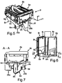
- Fig. 5 is an embodiment of the Ein Hughesan angel 8 with the dispenser 8a shown in a perspective view.
- the dispensing tray 8a comprises an upper part 8b and a lower part 8c, which are produced as separate parts, for example as one-piece injection-molded parts, and can be connected to one another, for example can be latched.
- a water supply device 8d is formed with a water receiving trough in the lower part 8c.
- the water receiving trough is in the present embodiment as shown in FIG Fig. 7 showing a section AA through the flushing assembly 8 along the xz plane, a siphon.
- an outlet connection 8e is formed, to which the line section 18a can be connected via the line 9a.
- the line section 18b can then be connected via the line 9b.
- a venting channel 8g is formed in the outlet connection 8e and in a further continuation, the illustration here being shown partially broken away, so that it is possible to see into the interior of the channel 8g.
- the design of the dispenser tray 8a is also provided so that in the lower part 8c, a sub-channel 8k is formed, which forms with a further sub-channel in the upper part 8b the closed entire vent channel 8g.
- the upper part 8b has a guide wall, not shown, through which in the assembled state of the upper part 8b with the lower part 8c, an interior of the dispenser 8a is divided into two Einmonykanäle 8l and 8m.
- a first flushing channel 8m is with the water supply device as a vapor barrier educated.
- a second dispensing channel 8 l is formed with a water supply device as a connection to the tub 3.
- a dividing wall 31 is then produced and provided as a one-piece, separate component, which can then be inserted into the lower part 8c in the region of the water trough, in particular can be positioned there in a latching manner.
- Fig. 7 For this purpose, the already positioned final state of this partition 31 is shown, which then results in the siphon-like configuration of the water well of the water supply device 8d and according to the arrows shown in FIG Fig. 7 the flow path of the liquid medium is shown.
- Fig. 8 to a side view is shown, in which the partition wall 31 is removed.
- a very specific water supply system for the flushing is formed, which reliably prevents the escape of steam from the tub 3 during the washing and drying cycle. This is done via the water reservoir in the integrated siphon 8n in the dispenser 8a.
- the Fig. 9 shows in a section BB through the Ein Hughesan angel 8 along the xz plane, the water supply device 8d with the water receiving trough, which is filled up to the overflow level 34 of the second overflow with the original medium 33, in particular with water or liquid. If the water supply device 8d now supplies further water or liquid, it will reach the outlet connection 8e via the second overflow along the arrow 36, since the overflow level 34 of the second overflow is lower than the overflow 35 of the first overflow.
- an overflow channel 38 is arranged between the outlet nozzle 8e and the water supply device 8d.
- the overflow channel is in the range arranged the second overflow.
- the level of the overflow channel is lower than the first overflow level 34. If now more water or liquid is supplied to the water supply device 8d per unit time than can flow off via the overflow channel 38, the level of the supply medium 33 in the water supply device 8d will increase. When the level of the original medium 33 has reached the first overflow level 35, the water or liquid supplied to the original medium 33 will flow out via the outlet nozzle 8f. Since the cross section of the overflow channel is smaller than the cross section of the outlet nozzle 8f, a larger proportion of the supplied water or the liquid via the outlet nozzle 8f than the outlet nozzle 8e from the Ein Albanyan angel 8 exit.
- a direct wetting of the laundry items should be made only during a dispensing process.
- the water or the liquid flows through the lines 9b and 18b.
- the cross section of the overflow channel 38 is adapted to the predetermined water inlet stream or the liquid flow, that in a flushing the water supplied via the port 5 will essentially emerge from the outlet nozzle 8f and only a small leakage will flow through the overflow channel 38.
- a direct wetting of introduced in the washing machine 1 laundry is possible because according to the embodiment of the outlet spigot 8f is connected via the line 9b with the feed point 11 b and the feed point 11b from its exiting water or liquid directly into the drum 3 and thus steers on the laundry items.
- the water or liquid remaining in the water supply device 8d causes the vapor or odor trap.
- the master medium 33 during the other operation of the washing machine 1 due to device vibrations or vibrations or pressure fluctuations, especially when closing and opening a loading opening of the washing machine 1, in motion. Such a movement is in Fig. 9 represented by the arrow 37.
- the movement of the master medium 33 causes the same to overflow, which is why a portion of the master medium 33 will escape via the lower overflow, that is to say the second overflow. This part will then drain via the overflow channel 38 and the outlet nozzle 8e in the line 9a.
- FIG. 9 represented by the arrow 37.
- the line 9a is shown connected to the tub 2 and not with the sleeve 10, which is why in such a spill an unwanted wetting of the laundry with the template medium 33 can be avoided. Therefore, it can also be ruled out that when the items of laundry that have just been thrown are removed by opening the loading opening, which can lead to pressure fluctuations in the water supply system, the items of laundry are rewetted with original medium 33 emerging from the water supply device 8d.
- the line section 18a will be explained in more detail below.
- the washing machine 1 and the control of the same is designed so that during a flushing process either the water or the liquid via the line section 18a or via the line section 18b to the tub 2 and the drum 3 can be fed.
- FIG. 2 For this purpose, a perspective view of the inlet section 4a with the line section 18a is shown.
- the line section 18a has a first upper end 19, which is connected to a connecting piece 20 of the dispensing tray 8a. At this first end 19 opens a feed channel 21 and separated from it a ventilation duct 22 at this first end 19, these two channels 21 and 22 for connection with continuations to opening and beyond also designed separated from each other.
- the line section 18a which represents the inlet section 4a in the exemplary embodiment, is a one-piece injection-molded part. It is predominantly rigid and has only in a central portion of a flexible channel portion 23 which is formed as a corrugated tube.
- Fig. 3 is a partially sketched as a sectional view view of the line section 18a according to Fig. 2 shown.
- the ventilation channel 22 is separated from the feed channel 21 by a boundary wall 24.
- the first end 19 in terms of altitude is a level considered upper end.
- the ventilation channel 22 opens with its upper end 19 facing away from the lower end 25 in the curved feed channel 21.
- a respective confluence point 26 is formed level higher level than a liquid level 27 in the feed channel 21.
- the vapor barrier is formed.
- This fluid level 27 lies level under the junction point 26.
- a problem-free removal of the process air 28, which is represented by the corresponding arrow, can thus take place via the inlet section 4a and the ventilation channel 22 into the dispenser 8a.
- the flexible channel section 23 is formed in the supply channel 21 and thus arranged after the junction 26 of the ventilation channel 22.
- the confluence point 26 is considered level arranged above a kink portion 32 of the feed channel 21, said kink portion 32 is arranged following the bend of the feed channel 21, in which bend the vapor barrier is formed. Even if a corresponding over spilling of the liquid takes place via this bend region 32 or the liquid level 27 would rise to this bend 32, the problem-free aeration process is still possible via the ventilation channel 22.
- This ventilation channel 22 then opens, as already mentioned, in a ventilation channel not shown in detail in the dispenser 8a, where the venting channel is then guided so that it contacts with a boundary wall, which limits the volume range in which the liquid medium is contained.
- the process air is guided along a condensation area for as long as possible and then forward again from the latter, in order in particular to be able to exit from the dispensing tray 8a at the front.
- Fig. 5 represented in the connected state of the line section 18a at the outlet connection 8e via the ventilation duct 22, the air in accordance with the arrow direction 30 shown in the vent passage 8g in the dispenser 8a. This is guided from the front end of the dispensing tray 8a, on which the outlet nozzle 8e is formed, over the entire depth (y-direction) to the rear, and blown out from there back to front and via a front opening 8h from the dispenser 8a.
- the very narrow vent channel 8g is bounded inwardly by a boundary wall 8i.
- This wall 8i is also at the same time the boundary wall of a water receiving space 8j in the lower part 8c.
- the water therein, which optionally also has a detergent, is then passed through the feed channel 21 to the tub 2.
- vent channel 8g Due to the specifically designed and arranged vent channel 8g, the air is passed as long as possible in the area of the liquid receiving water receiving space 8j, so that a corresponding condensation can take place.
Landscapes
- Engineering & Computer Science (AREA)
- Textile Engineering (AREA)
- Detail Structures Of Washing Machines And Dryers (AREA)
Claims (9)
- Dispositif d'introduction de lessive (8) pour un appareil ménager (1) destiné à l'entretien du linge, avec un bac à lessive (8a) présentant une partie supérieure (8b) et une partie inférieure (8c) combinable à celle-ci, dans lequel un dispositif de départ d'eau (8d) avec une cavité d'accueil d'eau est exécuté dans la partie inférieure (8c), un raccord d'écoulement (8e, 8f) sur la partie inférieure (8c), lequel débouche dans la cavité d'accueil d'eau et un siphon (8n) entre le raccord d'écoulement (8e, 8f) et un espace d'accueil d'eau (8j) exécuté dans la partie inférieure (8c), dans lequel le siphon (8n) présente un premier trop-plein vers le raccord d'écoulement (8f) et un deuxième trop-plein vers une sortie supplémentaire, en particulier un deuxième raccord d'écoulement (8e), le niveau de débordement (35) du premier trop-plein étant supérieur au niveau de débordement (34) du deuxième trop-plein, caractérisé en ce qu'un canal de trop-plein (38) est disposé entre le dispositif de départ d'eau (8d) et la sortie supplémentaire, lequel canal présente une surface de section inférieure à la surface de section du raccord d'écoulement (8f) et son emplacement en hauteur est moins élevé que le niveau de débordement (35) du premier trop-plein.
- Dispositif d'introduction de lessive (8) selon la revendication 1, caractérisé en ce que le canal de trop-plein (38) constitue le deuxième trop-plein.
- Dispositif d'introduction de lessive selon l'une des revendications 1 ou 2, caractérisé en ce qu'une paroi de séparation (31) distincte par rapport à la partie inférieure (8c) est exécutée, laquelle se positionne sur la partie inférieure (8c), et en ce que la paroi de séparation (31) mise en place constitue le siphon (8n) entre le raccord d'écoulement (8e, 8f) et l'espace d'accueil d'eau (8j) exécuté dans la partie inférieure (8c).
- Dispositif d'introduction de lessive (8) selon la revendication 3, caractérisé en ce que la paroi de séparation (31) est une pièce en plastique réalisée en une seule pièce.
- Dispositif d'introduction de lessive (8) selon l'une des revendications 3 ou 4, caractérisé en ce que la paroi de séparation (31) se positionne par enclenchement sur la partie inférieure (8c).
- Dispositif d'introduction de lessive (8) selon l'une des revendications 3 à 5, caractérisé en ce que la partie supérieure (8b) présente une paroi de guidage à travers laquelle l'espace intérieur du bac à lessive (8a) est subdivisé en deux canaux à lessive (8l, 8m) dans l'état assemblé de la partie supérieure (8b) avec la partie inférieure (8c).
- Dispositif d'introduction de lessive (8) selon la revendication 6, caractérisé en ce qu'un deuxième canal à lessive (8l, 8m) est exécuté avec le dispositif de départ d'eau sous forme de raccordement à une cuve à lessive (2) de l'appareil ménager (1).
- Appareil ménager (1) pour l'entretien du linge, avec un dispositif d'introduction de lessive (8) selon l'une des revendications précédentes.
- Appareil ménager (1) selon la revendication 8, caractérisé en ce qu'il s'agit d'un lave-linge ou d'un sèche-linge.
Applications Claiming Priority (2)
| Application Number | Priority Date | Filing Date | Title |
|---|---|---|---|
| DE102012218549.6A DE102012218549A1 (de) | 2012-10-11 | 2012-10-11 | Einspülanordnung für ein Haushaltsgerät zur Pflege von Wäschestücken sowie Haushaltsgerät zur Pflege von Wäschestücken |
| PCT/EP2013/070535 WO2014056777A1 (fr) | 2012-10-11 | 2013-10-02 | Système de d'ajout de produits pour un appareil ménager destiné à l'entretien de pièces de linge ainsi qu'appareil ménager pour l'entretien de pièces de linge |
Publications (2)
| Publication Number | Publication Date |
|---|---|
| EP2906745A1 EP2906745A1 (fr) | 2015-08-19 |
| EP2906745B1 true EP2906745B1 (fr) | 2016-07-20 |
Family
ID=49304940
Family Applications (1)
| Application Number | Title | Priority Date | Filing Date |
|---|---|---|---|
| EP13773701.1A Active EP2906745B1 (fr) | 2012-10-11 | 2013-10-02 | Dispositif d'introduction de lessive pour un appareil ménager destiné à l'entretien du linge et appareil ménager destiné à l'entretien du linge |
Country Status (6)
| Country | Link |
|---|---|
| EP (1) | EP2906745B1 (fr) |
| CN (1) | CN104781464B (fr) |
| DE (1) | DE102012218549A1 (fr) |
| PL (1) | PL2906745T3 (fr) |
| RU (1) | RU2611029C2 (fr) |
| WO (1) | WO2014056777A1 (fr) |
Families Citing this family (7)
| Publication number | Priority date | Publication date | Assignee | Title |
|---|---|---|---|---|
| CN106996016B (zh) * | 2017-05-17 | 2021-09-07 | 青岛海尔洗涤电器有限公司 | 一种洗衣机水盒结构及具有该水盒的洗衣机 |
| DE102017216516A1 (de) * | 2017-09-19 | 2019-03-21 | BSH Hausgeräte GmbH | Wäschepflegemaschine mit einer Einspülschale und einem Siphon |
| KR102628098B1 (ko) * | 2019-02-01 | 2024-01-23 | 엘지전자 주식회사 | 의류처리장치 |
| EP3690119B1 (fr) * | 2019-02-01 | 2023-06-14 | LG Electronics Inc. | Appareil de traitement du linge |
| DE102019212838A1 (de) * | 2019-08-27 | 2021-03-04 | BSH Hausgeräte GmbH | Anordnung zum Steuern einer Austrittsrichtung eines Fluids |
| DE102021106347A1 (de) | 2021-03-16 | 2022-09-22 | Miele & Cie. Kg | Waschmaschine und Verfahren zum Betrieb einer Waschmaschine |
| DE102021213577A1 (de) | 2021-12-01 | 2023-06-01 | BSH Hausgeräte GmbH | Siphon für ein Wäschepflegegerät |
Family Cites Families (13)
| Publication number | Priority date | Publication date | Assignee | Title |
|---|---|---|---|---|
| JPS54147659A (en) * | 1978-05-10 | 1979-11-19 | Hitachi Ltd | Automatic cleanser charger for automatic washing machine |
| FR2589170B1 (fr) * | 1985-10-25 | 1988-05-27 | Esswein Sa | Machine a laver munie d'une boite a produits a plusieurs compartiments |
| ITPN20020016A1 (it) * | 2002-03-19 | 2003-09-19 | Electrolux Home Products Corpo | Vaschetta per sostanze detergenti e macchina lavatrice comprendente detta vaschetta. |
| KR101122788B1 (ko) * | 2004-06-24 | 2012-03-21 | 엘지전자 주식회사 | 세탁기 블리치 박스의 오버 플로 방지 구조 |
| DE102004060709A1 (de) | 2004-12-16 | 2006-06-22 | BSH Bosch und Siemens Hausgeräte GmbH | Einspülanordung mit Wasservorlauf für eine Waschmaschine |
| DE102005012424A1 (de) * | 2005-03-17 | 2006-09-21 | BSH Bosch und Siemens Hausgeräte GmbH | Waschmittel-Einspüleneinrichtung |
| DE102006029953A1 (de) | 2006-06-29 | 2008-01-03 | BSH Bosch und Siemens Hausgeräte GmbH | Waschmaschine mit einem steuerbaren Frischwasserzulauf und Verfahren zum Betreiben einer solchen Waschmaschine |
| US7895864B2 (en) * | 2007-10-23 | 2011-03-01 | Electrolux Home Products, Inc. | Laundry additive dispenser |
| US8074476B2 (en) * | 2009-09-21 | 2011-12-13 | Alliance Laundry Systems Llc | Washer extractor with improved chemical dispenser |
| DE102011089395A1 (de) * | 2011-12-21 | 2013-06-27 | BSH Bosch und Siemens Hausgeräte GmbH | Einspülanordnung für ein Haushaltsgerät zur Pflege von Wäschestücken sowie Haushaltsgerät zur Pflege von Wäschestücken |
| DE102011089390A1 (de) * | 2011-12-21 | 2013-06-27 | BSH Bosch und Siemens Hausgeräte GmbH | Einspülanordnung für ein Haushaltsgerät zur Pflege von Wäschestücken sowie Haushaltsgerät zur Pflege von Wäschestücken |
| DE102011089387A1 (de) * | 2011-12-21 | 2013-06-27 | BSH Bosch und Siemens Hausgeräte GmbH | Haushaltsgerät zur Pflege von Wäschestücken mit einer Einspülschale und einem Laugenbehälter |
| EP2794977B1 (fr) * | 2011-12-21 | 2016-03-16 | BSH Hausgeräte GmbH | Dispositif d'introduction de lessive pour un appareil ménager destiné à l'entretien du linge et appareil ménager destiné à l'entretien du linge |
-
2012
- 2012-10-11 DE DE102012218549.6A patent/DE102012218549A1/de not_active Withdrawn
-
2013
- 2013-10-02 PL PL13773701T patent/PL2906745T3/pl unknown
- 2013-10-02 WO PCT/EP2013/070535 patent/WO2014056777A1/fr active Application Filing
- 2013-10-02 EP EP13773701.1A patent/EP2906745B1/fr active Active
- 2013-10-02 RU RU2015115217A patent/RU2611029C2/ru active
- 2013-10-02 CN CN201380053364.XA patent/CN104781464B/zh active Active
Also Published As
| Publication number | Publication date |
|---|---|
| CN104781464B (zh) | 2016-11-16 |
| EP2906745A1 (fr) | 2015-08-19 |
| WO2014056777A1 (fr) | 2014-04-17 |
| DE102012218549A1 (de) | 2014-04-17 |
| CN104781464A (zh) | 2015-07-15 |
| PL2906745T3 (pl) | 2017-01-31 |
| RU2015115217A (ru) | 2016-12-10 |
| RU2611029C2 (ru) | 2017-02-17 |
Similar Documents
| Publication | Publication Date | Title |
|---|---|---|
| EP2794978B1 (fr) | Dispositif d'introduction de lessive pour un appareil ménager destiné à l'entretien du linge et appareil ménager destiné à l'entretien du linge | |
| EP2906745B1 (fr) | Dispositif d'introduction de lessive pour un appareil ménager destiné à l'entretien du linge et appareil ménager destiné à l'entretien du linge | |
| EP1992731B1 (fr) | Machine de traitement du linge à ouverture frontale | |
| EP2521813B1 (fr) | Dispositif pour nettoyer un élément d'un appareil de séchage et appareil de séchage équipé d'un tel dispositif | |
| EP2794981B1 (fr) | Appareil ménager permettant l'entretien du linge, comprenant une coquille d'injection et une cuve de lavage | |
| EP2794977B1 (fr) | Dispositif d'introduction de lessive pour un appareil ménager destiné à l'entretien du linge et appareil ménager destiné à l'entretien du linge | |
| EP2478141B1 (fr) | Appareil électroménager véhiculant de l'eau équipé d'un dispositif d'alimentation en eau | |
| EP3981905A1 (fr) | Lave-linge ayant une fonction de vaporisation et procédé de vaporisation du linge | |
| EP1861536B1 (fr) | Dispositif de distribution de detergent | |
| WO2006063896A1 (fr) | Dispositif d'introduction de detergent avec arrivee d'eau, destine a un lave-linge | |
| DE102011089390A1 (de) | Einspülanordnung für ein Haushaltsgerät zur Pflege von Wäschestücken sowie Haushaltsgerät zur Pflege von Wäschestücken | |
| EP2348152A1 (fr) | Lave-linge doté d'un dispositif d'écoulement | |
| DE102011053950B4 (de) | Waschmaschine mit einem in einem Maschinengehäuse angeordneten Laugenbehälter | |
| DE1909698A1 (de) | Vorrichtung zum Abgeben von Reinigungsmitteln an Waschmaschinen | |
| DE202011104270U1 (de) | Wasserführendes Haushaltsgerät mit einer Wasservorlageeinrichtung | |
| DE19909310B4 (de) | Wäschebehandlungsmaschine | |
| DE19921441B4 (de) | Haushaltgerät, insbesondere Waschmaschine, Waschtrockner oder Geschirrspülmaschine | |
| EP2041356B1 (fr) | Section de pompage de la lessive | |
| DE102021212638A1 (de) | Einspülsystem, wasserführendes Haushaltsgerät und Verfahren zum Leiten von Fluid | |
| EP3757275B1 (fr) | Appareil électroménager destiné au traitement du linge | |
| DE102015224667B3 (de) | Wäschepflegegerät mit einer Belüftungsleitung | |
| DE102015117046A1 (de) | Waschmaschine |
Legal Events
| Date | Code | Title | Description |
|---|---|---|---|
| PUAI | Public reference made under article 153(3) epc to a published international application that has entered the european phase |
Free format text: ORIGINAL CODE: 0009012 |
|
| 17P | Request for examination filed |
Effective date: 20150511 |
|
| AK | Designated contracting states |
Kind code of ref document: A1 Designated state(s): AL AT BE BG CH CY CZ DE DK EE ES FI FR GB GR HR HU IE IS IT LI LT LU LV MC MK MT NL NO PL PT RO RS SE SI SK SM TR |
|
| AX | Request for extension of the european patent |
Extension state: BA ME |
|
| DAX | Request for extension of the european patent (deleted) | ||
| GRAP | Despatch of communication of intention to grant a patent |
Free format text: ORIGINAL CODE: EPIDOSNIGR1 |
|
| INTG | Intention to grant announced |
Effective date: 20160307 |
|
| GRAS | Grant fee paid |
Free format text: ORIGINAL CODE: EPIDOSNIGR3 |
|
| GRAA | (expected) grant |
Free format text: ORIGINAL CODE: 0009210 |
|
| AK | Designated contracting states |
Kind code of ref document: B1 Designated state(s): AL AT BE BG CH CY CZ DE DK EE ES FI FR GB GR HR HU IE IS IT LI LT LU LV MC MK MT NL NO PL PT RO RS SE SI SK SM TR |
|
| REG | Reference to a national code |
Ref country code: GB Ref legal event code: FG4D Free format text: NOT ENGLISH |
|
| REG | Reference to a national code |
Ref country code: CH Ref legal event code: EP |
|
| REG | Reference to a national code |
Ref country code: IE Ref legal event code: FG4D Free format text: LANGUAGE OF EP DOCUMENT: GERMAN |
|
| REG | Reference to a national code |
Ref country code: AT Ref legal event code: REF Ref document number: 814199 Country of ref document: AT Kind code of ref document: T Effective date: 20160815 |
|
| REG | Reference to a national code |
Ref country code: DE Ref legal event code: R096 Ref document number: 502013003829 Country of ref document: DE |
|
| REG | Reference to a national code |
Ref country code: LT Ref legal event code: MG4D |
|
| REG | Reference to a national code |
Ref country code: NL Ref legal event code: MP Effective date: 20160720 |
|
| PG25 | Lapsed in a contracting state [announced via postgrant information from national office to epo] |
Ref country code: RS Free format text: LAPSE BECAUSE OF FAILURE TO SUBMIT A TRANSLATION OF THE DESCRIPTION OR TO PAY THE FEE WITHIN THE PRESCRIBED TIME-LIMIT Effective date: 20160720 Ref country code: LT Free format text: LAPSE BECAUSE OF FAILURE TO SUBMIT A TRANSLATION OF THE DESCRIPTION OR TO PAY THE FEE WITHIN THE PRESCRIBED TIME-LIMIT Effective date: 20160720 Ref country code: FI Free format text: LAPSE BECAUSE OF FAILURE TO SUBMIT A TRANSLATION OF THE DESCRIPTION OR TO PAY THE FEE WITHIN THE PRESCRIBED TIME-LIMIT Effective date: 20160720 Ref country code: NL Free format text: LAPSE BECAUSE OF FAILURE TO SUBMIT A TRANSLATION OF THE DESCRIPTION OR TO PAY THE FEE WITHIN THE PRESCRIBED TIME-LIMIT Effective date: 20160720 Ref country code: IS Free format text: LAPSE BECAUSE OF FAILURE TO SUBMIT A TRANSLATION OF THE DESCRIPTION OR TO PAY THE FEE WITHIN THE PRESCRIBED TIME-LIMIT Effective date: 20161120 Ref country code: NO Free format text: LAPSE BECAUSE OF FAILURE TO SUBMIT A TRANSLATION OF THE DESCRIPTION OR TO PAY THE FEE WITHIN THE PRESCRIBED TIME-LIMIT Effective date: 20161020 Ref country code: HR Free format text: LAPSE BECAUSE OF FAILURE TO SUBMIT A TRANSLATION OF THE DESCRIPTION OR TO PAY THE FEE WITHIN THE PRESCRIBED TIME-LIMIT Effective date: 20160720 |
|
| PG25 | Lapsed in a contracting state [announced via postgrant information from national office to epo] |
Ref country code: BE Free format text: LAPSE BECAUSE OF NON-PAYMENT OF DUE FEES Effective date: 20161031 Ref country code: GR Free format text: LAPSE BECAUSE OF FAILURE TO SUBMIT A TRANSLATION OF THE DESCRIPTION OR TO PAY THE FEE WITHIN THE PRESCRIBED TIME-LIMIT Effective date: 20161021 Ref country code: PT Free format text: LAPSE BECAUSE OF FAILURE TO SUBMIT A TRANSLATION OF THE DESCRIPTION OR TO PAY THE FEE WITHIN THE PRESCRIBED TIME-LIMIT Effective date: 20161121 Ref country code: SE Free format text: LAPSE BECAUSE OF FAILURE TO SUBMIT A TRANSLATION OF THE DESCRIPTION OR TO PAY THE FEE WITHIN THE PRESCRIBED TIME-LIMIT Effective date: 20160720 Ref country code: ES Free format text: LAPSE BECAUSE OF FAILURE TO SUBMIT A TRANSLATION OF THE DESCRIPTION OR TO PAY THE FEE WITHIN THE PRESCRIBED TIME-LIMIT Effective date: 20160720 Ref country code: LV Free format text: LAPSE BECAUSE OF FAILURE TO SUBMIT A TRANSLATION OF THE DESCRIPTION OR TO PAY THE FEE WITHIN THE PRESCRIBED TIME-LIMIT Effective date: 20160720 |
|
| REG | Reference to a national code |
Ref country code: DE Ref legal event code: R097 Ref document number: 502013003829 Country of ref document: DE |
|
| PG25 | Lapsed in a contracting state [announced via postgrant information from national office to epo] |
Ref country code: RO Free format text: LAPSE BECAUSE OF FAILURE TO SUBMIT A TRANSLATION OF THE DESCRIPTION OR TO PAY THE FEE WITHIN THE PRESCRIBED TIME-LIMIT Effective date: 20160720 Ref country code: EE Free format text: LAPSE BECAUSE OF FAILURE TO SUBMIT A TRANSLATION OF THE DESCRIPTION OR TO PAY THE FEE WITHIN THE PRESCRIBED TIME-LIMIT Effective date: 20160720 |
|
| PLBE | No opposition filed within time limit |
Free format text: ORIGINAL CODE: 0009261 |
|
| STAA | Information on the status of an ep patent application or granted ep patent |
Free format text: STATUS: NO OPPOSITION FILED WITHIN TIME LIMIT |
|
| PG25 | Lapsed in a contracting state [announced via postgrant information from national office to epo] |
Ref country code: DK Free format text: LAPSE BECAUSE OF FAILURE TO SUBMIT A TRANSLATION OF THE DESCRIPTION OR TO PAY THE FEE WITHIN THE PRESCRIBED TIME-LIMIT Effective date: 20160720 Ref country code: SM Free format text: LAPSE BECAUSE OF FAILURE TO SUBMIT A TRANSLATION OF THE DESCRIPTION OR TO PAY THE FEE WITHIN THE PRESCRIBED TIME-LIMIT Effective date: 20160720 Ref country code: BG Free format text: LAPSE BECAUSE OF FAILURE TO SUBMIT A TRANSLATION OF THE DESCRIPTION OR TO PAY THE FEE WITHIN THE PRESCRIBED TIME-LIMIT Effective date: 20161020 Ref country code: CZ Free format text: LAPSE BECAUSE OF FAILURE TO SUBMIT A TRANSLATION OF THE DESCRIPTION OR TO PAY THE FEE WITHIN THE PRESCRIBED TIME-LIMIT Effective date: 20160720 Ref country code: SK Free format text: LAPSE BECAUSE OF FAILURE TO SUBMIT A TRANSLATION OF THE DESCRIPTION OR TO PAY THE FEE WITHIN THE PRESCRIBED TIME-LIMIT Effective date: 20160720 |
|
| REG | Reference to a national code |
Ref country code: CH Ref legal event code: PL |
|
| 26N | No opposition filed |
Effective date: 20170421 |
|
| REG | Reference to a national code |
Ref country code: IE Ref legal event code: MM4A |
|
| REG | Reference to a national code |
Ref country code: FR Ref legal event code: ST Effective date: 20170630 |
|
| PG25 | Lapsed in a contracting state [announced via postgrant information from national office to epo] |
Ref country code: FR Free format text: LAPSE BECAUSE OF NON-PAYMENT OF DUE FEES Effective date: 20161102 Ref country code: CH Free format text: LAPSE BECAUSE OF NON-PAYMENT OF DUE FEES Effective date: 20161031 Ref country code: LI Free format text: LAPSE BECAUSE OF NON-PAYMENT OF DUE FEES Effective date: 20161031 |
|
| PG25 | Lapsed in a contracting state [announced via postgrant information from national office to epo] |
Ref country code: LU Free format text: LAPSE BECAUSE OF NON-PAYMENT OF DUE FEES Effective date: 20161002 Ref country code: SI Free format text: LAPSE BECAUSE OF FAILURE TO SUBMIT A TRANSLATION OF THE DESCRIPTION OR TO PAY THE FEE WITHIN THE PRESCRIBED TIME-LIMIT Effective date: 20160720 |
|
| PG25 | Lapsed in a contracting state [announced via postgrant information from national office to epo] |
Ref country code: IE Free format text: LAPSE BECAUSE OF NON-PAYMENT OF DUE FEES Effective date: 20161002 |
|
| REG | Reference to a national code |
Ref country code: BE Ref legal event code: MM Effective date: 20161031 |
|
| PG25 | Lapsed in a contracting state [announced via postgrant information from national office to epo] |
Ref country code: HU Free format text: LAPSE BECAUSE OF FAILURE TO SUBMIT A TRANSLATION OF THE DESCRIPTION OR TO PAY THE FEE WITHIN THE PRESCRIBED TIME-LIMIT; INVALID AB INITIO Effective date: 20131002 |
|
| PG25 | Lapsed in a contracting state [announced via postgrant information from national office to epo] |
Ref country code: MC Free format text: LAPSE BECAUSE OF FAILURE TO SUBMIT A TRANSLATION OF THE DESCRIPTION OR TO PAY THE FEE WITHIN THE PRESCRIBED TIME-LIMIT Effective date: 20160720 Ref country code: MT Free format text: LAPSE BECAUSE OF FAILURE TO SUBMIT A TRANSLATION OF THE DESCRIPTION OR TO PAY THE FEE WITHIN THE PRESCRIBED TIME-LIMIT Effective date: 20160720 Ref country code: MK Free format text: LAPSE BECAUSE OF FAILURE TO SUBMIT A TRANSLATION OF THE DESCRIPTION OR TO PAY THE FEE WITHIN THE PRESCRIBED TIME-LIMIT Effective date: 20160720 Ref country code: CY Free format text: LAPSE BECAUSE OF FAILURE TO SUBMIT A TRANSLATION OF THE DESCRIPTION OR TO PAY THE FEE WITHIN THE PRESCRIBED TIME-LIMIT Effective date: 20160720 |
|
| PG25 | Lapsed in a contracting state [announced via postgrant information from national office to epo] |
Ref country code: AL Free format text: LAPSE BECAUSE OF FAILURE TO SUBMIT A TRANSLATION OF THE DESCRIPTION OR TO PAY THE FEE WITHIN THE PRESCRIBED TIME-LIMIT Effective date: 20160720 |
|
| PGFP | Annual fee paid to national office [announced via postgrant information from national office to epo] |
Ref country code: IT Payment date: 20181022 Year of fee payment: 6 |
|
| REG | Reference to a national code |
Ref country code: AT Ref legal event code: MM01 Ref document number: 814199 Country of ref document: AT Kind code of ref document: T Effective date: 20181002 |
|
| PG25 | Lapsed in a contracting state [announced via postgrant information from national office to epo] |
Ref country code: AT Free format text: LAPSE BECAUSE OF NON-PAYMENT OF DUE FEES Effective date: 20181002 |
|
| PG25 | Lapsed in a contracting state [announced via postgrant information from national office to epo] |
Ref country code: IT Free format text: LAPSE BECAUSE OF NON-PAYMENT OF DUE FEES Effective date: 20191002 |
|
| REG | Reference to a national code |
Ref country code: DE Ref legal event code: R084 Ref document number: 502013003829 Country of ref document: DE |
|
| PGFP | Annual fee paid to national office [announced via postgrant information from national office to epo] |
Ref country code: TR Payment date: 20230920 Year of fee payment: 11 |
|
| PGFP | Annual fee paid to national office [announced via postgrant information from national office to epo] |
Ref country code: PL Payment date: 20230922 Year of fee payment: 11 |
|
| PGFP | Annual fee paid to national office [announced via postgrant information from national office to epo] |
Ref country code: GB Payment date: 20231025 Year of fee payment: 11 |
|
| PGFP | Annual fee paid to national office [announced via postgrant information from national office to epo] |
Ref country code: DE Payment date: 20231031 Year of fee payment: 11 |