EP2906320B1 - Selbsttragendes gefaltetes blattmaterial, filterelemente - Google Patents
Selbsttragendes gefaltetes blattmaterial, filterelemente Download PDFInfo
- Publication number
- EP2906320B1 EP2906320B1 EP13783164.0A EP13783164A EP2906320B1 EP 2906320 B1 EP2906320 B1 EP 2906320B1 EP 13783164 A EP13783164 A EP 13783164A EP 2906320 B1 EP2906320 B1 EP 2906320B1
- Authority
- EP
- European Patent Office
- Prior art keywords
- pleats
- major
- pleat
- minor
- media pack
- Prior art date
- Legal status (The legal status is an assumption and is not a legal conclusion. Google has not performed a legal analysis and makes no representation as to the accuracy of the status listed.)
- Active
Links
- 239000000463 material Substances 0.000 title description 12
- 238000001914 filtration Methods 0.000 claims description 58
- 238000007373 indentation Methods 0.000 claims description 14
- 239000012530 fluid Substances 0.000 claims description 13
- 230000008901 benefit Effects 0.000 description 9
- 238000000034 method Methods 0.000 description 8
- 150000001875 compounds Chemical class 0.000 description 4
- 238000004519 manufacturing process Methods 0.000 description 4
- 238000004382 potting Methods 0.000 description 4
- 239000000356 contaminant Substances 0.000 description 3
- 230000000873 masking effect Effects 0.000 description 3
- 238000000465 moulding Methods 0.000 description 3
- 239000000853 adhesive Substances 0.000 description 2
- 230000001070 adhesive effect Effects 0.000 description 2
- 238000010276 construction Methods 0.000 description 2
- 230000007423 decrease Effects 0.000 description 2
- 239000010432 diamond Substances 0.000 description 2
- 239000007788 liquid Substances 0.000 description 2
- JOYRKODLDBILNP-UHFFFAOYSA-N Ethyl urethane Chemical compound CCOC(N)=O JOYRKODLDBILNP-UHFFFAOYSA-N 0.000 description 1
- 239000004831 Hot glue Substances 0.000 description 1
- 230000001154 acute effect Effects 0.000 description 1
- 230000015572 biosynthetic process Effects 0.000 description 1
- 229920002678 cellulose Polymers 0.000 description 1
- 239000001913 cellulose Substances 0.000 description 1
- 229910003460 diamond Inorganic materials 0.000 description 1
- 239000000835 fiber Substances 0.000 description 1
- 229920000642 polymer Polymers 0.000 description 1
- 238000007789 sealing Methods 0.000 description 1
- 230000003068 static effect Effects 0.000 description 1
- 238000011144 upstream manufacturing Methods 0.000 description 1
Images


Classifications
-
- B—PERFORMING OPERATIONS; TRANSPORTING
- B01—PHYSICAL OR CHEMICAL PROCESSES OR APPARATUS IN GENERAL
- B01D—SEPARATION
- B01D29/00—Filters with filtering elements stationary during filtration, e.g. pressure or suction filters, not covered by groups B01D24/00 - B01D27/00; Filtering elements therefor
- B01D29/11—Filters with filtering elements stationary during filtration, e.g. pressure or suction filters, not covered by groups B01D24/00 - B01D27/00; Filtering elements therefor with bag, cage, hose, tube, sleeve or like filtering elements
- B01D29/13—Supported filter elements
- B01D29/15—Supported filter elements arranged for inward flow filtration
- B01D29/21—Supported filter elements arranged for inward flow filtration with corrugated, folded or wound sheets
- B01D29/213—Supported filter elements arranged for inward flow filtration with corrugated, folded or wound sheets having a concertina shape
-
- B—PERFORMING OPERATIONS; TRANSPORTING
- B01—PHYSICAL OR CHEMICAL PROCESSES OR APPARATUS IN GENERAL
- B01D—SEPARATION
- B01D46/00—Filters or filtering processes specially modified for separating dispersed particles from gases or vapours
- B01D46/24—Particle separators, e.g. dust precipitators, using rigid hollow filter bodies
- B01D46/2403—Particle separators, e.g. dust precipitators, using rigid hollow filter bodies characterised by the physical shape or structure of the filtering element
- B01D46/2411—Filter cartridges
-
- B—PERFORMING OPERATIONS; TRANSPORTING
- B01—PHYSICAL OR CHEMICAL PROCESSES OR APPARATUS IN GENERAL
- B01D—SEPARATION
- B01D29/00—Filters with filtering elements stationary during filtration, e.g. pressure or suction filters, not covered by groups B01D24/00 - B01D27/00; Filtering elements therefor
- B01D29/11—Filters with filtering elements stationary during filtration, e.g. pressure or suction filters, not covered by groups B01D24/00 - B01D27/00; Filtering elements therefor with bag, cage, hose, tube, sleeve or like filtering elements
- B01D29/111—Making filtering elements
-
- B—PERFORMING OPERATIONS; TRANSPORTING
- B01—PHYSICAL OR CHEMICAL PROCESSES OR APPARATUS IN GENERAL
- B01D—SEPARATION
- B01D29/00—Filters with filtering elements stationary during filtration, e.g. pressure or suction filters, not covered by groups B01D24/00 - B01D27/00; Filtering elements therefor
- B01D29/11—Filters with filtering elements stationary during filtration, e.g. pressure or suction filters, not covered by groups B01D24/00 - B01D27/00; Filtering elements therefor with bag, cage, hose, tube, sleeve or like filtering elements
- B01D29/13—Supported filter elements
- B01D29/15—Supported filter elements arranged for inward flow filtration
- B01D29/21—Supported filter elements arranged for inward flow filtration with corrugated, folded or wound sheets
-
- B—PERFORMING OPERATIONS; TRANSPORTING
- B01—PHYSICAL OR CHEMICAL PROCESSES OR APPARATUS IN GENERAL
- B01D—SEPARATION
- B01D39/00—Filtering material for liquid or gaseous fluids
- B01D39/14—Other self-supporting filtering material ; Other filtering material
-
- B—PERFORMING OPERATIONS; TRANSPORTING
- B01—PHYSICAL OR CHEMICAL PROCESSES OR APPARATUS IN GENERAL
- B01D—SEPARATION
- B01D46/00—Filters or filtering processes specially modified for separating dispersed particles from gases or vapours
- B01D46/0001—Making filtering elements
-
- B—PERFORMING OPERATIONS; TRANSPORTING
- B01—PHYSICAL OR CHEMICAL PROCESSES OR APPARATUS IN GENERAL
- B01D—SEPARATION
- B01D46/00—Filters or filtering processes specially modified for separating dispersed particles from gases or vapours
- B01D46/0002—Casings; Housings; Frame constructions
-
- B—PERFORMING OPERATIONS; TRANSPORTING
- B01—PHYSICAL OR CHEMICAL PROCESSES OR APPARATUS IN GENERAL
- B01D—SEPARATION
- B01D46/00—Filters or filtering processes specially modified for separating dispersed particles from gases or vapours
- B01D46/0002—Casings; Housings; Frame constructions
- B01D46/0004—Details of removable closures, lids, caps or filter heads
-
- B—PERFORMING OPERATIONS; TRANSPORTING
- B01—PHYSICAL OR CHEMICAL PROCESSES OR APPARATUS IN GENERAL
- B01D—SEPARATION
- B01D46/00—Filters or filtering processes specially modified for separating dispersed particles from gases or vapours
- B01D46/0002—Casings; Housings; Frame constructions
- B01D46/0005—Mounting of filtering elements within casings, housings or frames
-
- B—PERFORMING OPERATIONS; TRANSPORTING
- B01—PHYSICAL OR CHEMICAL PROCESSES OR APPARATUS IN GENERAL
- B01D—SEPARATION
- B01D46/00—Filters or filtering processes specially modified for separating dispersed particles from gases or vapours
- B01D46/24—Particle separators, e.g. dust precipitators, using rigid hollow filter bodies
- B01D46/2403—Particle separators, e.g. dust precipitators, using rigid hollow filter bodies characterised by the physical shape or structure of the filtering element
- B01D46/2411—Filter cartridges
- B01D46/2414—End caps including additional functions or special forms
-
- B—PERFORMING OPERATIONS; TRANSPORTING
- B01—PHYSICAL OR CHEMICAL PROCESSES OR APPARATUS IN GENERAL
- B01D—SEPARATION
- B01D46/00—Filters or filtering processes specially modified for separating dispersed particles from gases or vapours
- B01D46/52—Particle separators, e.g. dust precipitators, using filters embodying folded corrugated or wound sheet material
- B01D46/521—Particle separators, e.g. dust precipitators, using filters embodying folded corrugated or wound sheet material using folded, pleated material
- B01D46/522—Particle separators, e.g. dust precipitators, using filters embodying folded corrugated or wound sheet material using folded, pleated material with specific folds, e.g. having different lengths
-
- B—PERFORMING OPERATIONS; TRANSPORTING
- B01—PHYSICAL OR CHEMICAL PROCESSES OR APPARATUS IN GENERAL
- B01D—SEPARATION
- B01D46/00—Filters or filtering processes specially modified for separating dispersed particles from gases or vapours
- B01D46/52—Particle separators, e.g. dust precipitators, using filters embodying folded corrugated or wound sheet material
- B01D46/521—Particle separators, e.g. dust precipitators, using filters embodying folded corrugated or wound sheet material using folded, pleated material
- B01D46/523—Particle separators, e.g. dust precipitators, using filters embodying folded corrugated or wound sheet material using folded, pleated material with means for maintaining spacing between the pleats or folds
-
- B—PERFORMING OPERATIONS; TRANSPORTING
- B01—PHYSICAL OR CHEMICAL PROCESSES OR APPARATUS IN GENERAL
- B01D—SEPARATION
- B01D46/00—Filters or filtering processes specially modified for separating dispersed particles from gases or vapours
- B01D46/52—Particle separators, e.g. dust precipitators, using filters embodying folded corrugated or wound sheet material
- B01D46/521—Particle separators, e.g. dust precipitators, using filters embodying folded corrugated or wound sheet material using folded, pleated material
- B01D46/525—Particle separators, e.g. dust precipitators, using filters embodying folded corrugated or wound sheet material using folded, pleated material which comprises flutes
-
- B—PERFORMING OPERATIONS; TRANSPORTING
- B01—PHYSICAL OR CHEMICAL PROCESSES OR APPARATUS IN GENERAL
- B01D—SEPARATION
- B01D2201/00—Details relating to filtering apparatus
- B01D2201/02—Filtering elements having a conical form
-
- B—PERFORMING OPERATIONS; TRANSPORTING
- B01—PHYSICAL OR CHEMICAL PROCESSES OR APPARATUS IN GENERAL
- B01D—SEPARATION
- B01D2201/00—Details relating to filtering apparatus
- B01D2201/12—Pleated filters
-
- B—PERFORMING OPERATIONS; TRANSPORTING
- B01—PHYSICAL OR CHEMICAL PROCESSES OR APPARATUS IN GENERAL
- B01D—SEPARATION
- B01D2201/00—Details relating to filtering apparatus
- B01D2201/12—Pleated filters
- B01D2201/122—Pleated filters with pleats of different length
-
- B—PERFORMING OPERATIONS; TRANSPORTING
- B01—PHYSICAL OR CHEMICAL PROCESSES OR APPARATUS IN GENERAL
- B01D—SEPARATION
- B01D2201/00—Details relating to filtering apparatus
- B01D2201/12—Pleated filters
- B01D2201/127—Pleated filters with means for keeping the spacing between the pleats
Definitions
- This disclosure relates to sheet material that is folded to maintain a degree of structural integrity and while the disclosure is aimed primarily at pleated filtration media used in media packs, filter elements, and methods of their manufacture, the disclosure can also be applied in other instances, where a folded sheet material can benefit from the structural integrity, flexibility and resilience offered by the present disclosure.
- Permeable sheets of filtration media are used widely to remove contaminants from fluid streams and in order to achieve optimal performance of the filtration media, the surface of the sheet that is exposed to the fluid stream needs to be large, but in order to avoid excessive size of filtration elements, the sheets need to fit into small volumes and are typically pleated to maximize the ratios between filtration surfaces exposed to the fluid streams and the overall dimensions of the filtration elements.
- filtration elements and the permeable sheets in them When exposed to fluid steams, these filtration elements and the permeable sheets in them are exposed to forces from the fluid streams and need to withstand these forces sufficiently to ensure continued acceptable operation of the filter element.
- pleated sheets of permeable filtration media are often prone to deflection and adjacent sheets are often too close together or touch and thus prevent a well dispersed flow pattern of the fluid - and reduce the available surface area of the filtration media for loading - a phenomenon known as "masking”.
- filtration elements made from sheets of permeable filtration media typically do not include structural supports for the filtration media, but rely on the structural integrity of the folded sheets themselves.
- Pleated filtration media are typically formed from continuous or rolled webs and pleats are formed perpendicular to the "machine" or “reel” direction of the media, i.e. to the continuous direction of the media as it comes from a source, such as a supply reel.
- Simple alternating "zigzag” pleats are commonly used and are simple to form, but are prone to deflection and masking, especially in cases of deep pleats.
- the present disclosure seeks to address at least some of the challenges mentioned above and in particular to provide elements of folded sheet material with improved structural stiffness, flexibility and compressibility, or maximizing surface area, which can be manufactured cost-effectively.
- a pleated media pack according to the present invention is defined in claim 1. Pleated media packs for use in filter elements are provided.
- a section of filtration media is folded in the pleats, with at least some pleats having a major pleat depth.
- the section of filtration media can be configured into a tube defining an interior volume with first and second opposite ends.
- An opening is at the first end.
- the opening has a diameter.
- a ratio of the pleat depth to the opening diameter is greater than 0.2.
- At least some of the pleats at one end of the media pack are inverted.
- the pleats will include major pleats defming the major pleat depth, and minor pleats having a minor pleat depth less than the major pleat depth.
- At least some of the pleats at the first end are inverted an opposite direction of the rest of the pleat, along at least a portion of the pleat length from the first end toward the second end.
- the second end will typically not have inverted pleats.
- At least either the major pleats or minor pleats at the first end are inverted. In some implementations, only one of the major pleats or minor pleats is inverted. In some implementations, both the major pleats and minor pleats are inverted an opposite direction of the rest of the pleat, along at least a portion of the pleat length from the first end toward the second end.
- Filter elements can be constructed from media packs as characterized above.
- the filter element has a first open end cap secured to the first end of the media pack, and a second end cap secured to the second end of the media pack.
- the first open end cap defines an outlet opening for an exit of filtered fluid.
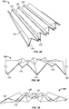
- a sheet 12 of permeable filter material is fed from a suitable feed stock of a filter medium, such as a reel and is scored on opposing sides of the sheet as shown in FIG. 1 .
- the score lines shown in solid lines are for folding the sheet 12 in one direction and the score lines shown in broken lines are for folding the sheet in the opposite direction - i.e. the scoring patterns in solid lines and in broken lines are made on opposing sides of the sheet.
- Additional chevron score lines 13 can be formed on the sheet 12, as shown in FIG. 2 , if desired.
- the score patterns can be made with the majority of lines aligned with the machine or reel direction (shown in FIGS. 1 and 2 with reference numeral 15), or if desired, the score pattern can be made with an orientation relative to the reel direction that is perpendicular to that shown in FIGS. 1 and 2 .
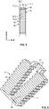
- the filtration element 14 includes a major pleated structure, a minor pleated structure and a plurality of indentations - all of which are formed simultaneously by folding the sheet 12 along the score lines.
- the major pleated structure is made up of a number of inclined walls 16 that extend in an alternating or zigzag configuration between parallel major pleats 17:
- the walls 16 are not planar and the pleats 17 are not linear and in order to assist in identifying them in the drawings, the pleats are identified by broken lines, with suffixes identifying the side of the filter element towards which the pleat protrudes.
- Pleats 17.1 protrudes upwards in the illustrated example and pleats 17.2 protrude downwards, with the sheet 12 and thus the filtration element 14 extending horizontally in an X-V plane and the upward and downward directions being in the Z direction, with reference to X, Y, and Z directions shown in FIGS. 3 to 4 .
- Each inclined wall 16 extends between a major pleat 17.1 along its top and an opposing major pleat 17.2 along its bottom.
- the minor pleated structure is made up of alternating or zigzagging minor pleats 18 formed in each of the inclined walls 16.
- Each of the minor pleats 18 protrude towards opposing sides of the sheet 12 in alternating fashion and for ease of reference, minor pleats that protrude upwardly are identified in the drawings with reference number 18.1 and minor pleats protruding downwardly are identified with reference number 18.2.
- Each of the minor pleats 18 extends transversely between the two major pleats 17 at the opposing upper and lower edges of the inclined wall 16.
- the upwardly facing minor pleats 18.1 of adjacent inclined walls 16 are aligned in the Y direction and likewise, the downwardly facing minor pleats 18.2 are aligned in the Y direction.
- each indentation 19 is made up of two isosceles triangles 20, on opposing sides of a common base line 21.
- each base line 21 extends between upwardly protruding minor pleats 18.1 on opposing sides of the major pleat 17.1.
- the base line 21 is also aligned with the minor pleats 18.1 in the Y direction.
- the apex of each triangle 20 is at the junction where downwardly protruding minor pleats 18.2 on opposing sides of the major pleat 17.1 intersect.
- each base line 21 extends between downwardly protruding minor pleats 18.2 on opposing sides of the major pleat 17.2.
- the base line 21 is also aligned with the minor pleats 18.2 in the Y direction.
- the apex of each triangle 6 is at the junction where upwardly protruding minor pleats 18.1 on opposing sides of the major pleat 17.2 intersect.
- the minor pleats 18 are formed first off the roll of sheet material in the Y direction (which is aligned with the machine reel direction 15 in the illustrated example) and subsequently, the major pleats 17 are formed in the Z direction.
- a continuous sheet that has been folded to form: a major pleated structure comprising inclined walls that are connected continuously at generally parallel alternating major pleats, said major pleats extending along opposing edges of each inclined wall and said major pleats protruding towards opposing sides of the sheet in alternating fashion; a minor pleated structure formed in each of the inclined walls of the major pleated structure, with alternating minor pleats formed in each of said inclined walls, each of said minor pleats protruding towards opposing sides of the sheet in alternating fashion and each of said minor pleats extending transversely between the major pleats at opposing edges of the inclined wall, with minor pleats of adjacent inclined walls being generally aligned on opposing sides of each major pleat; and indentations formed along each major pleat, each indentation comprising two triangles on opposing sides of a common base line, said base line extending between and being aligned with two minor pleats, said minor pleats being on opposing sides of
- the dimensions and proportions of the score patterns shown in FIGS. 1 and 2 and thus of the filtration element 14 can be varied, to suit different applications.
- the diamond shapes (the “diamonds" being formed by the isosceles triangles 20) of the indentations 19 can be varied to adjust the ultimate folding angle of the major pleats 17.
- the zigzag configurations of the major and minor pleats 17, 18, as well as the indentations 19, allow the filtration element 14 to be compressed or expanded easily in the X and Y directions or to be curved in any direction and the resilience of the sheet material 12 causes the major and minor pleats 17, 18 to remain spaced apart generally equally.
- the chevron score lines 13 shown at each alternate major pleat 17 in FIG. 2 can be advantageous in opening up the upstream ends of the major pleats, to reduce pressure drop and provide greater volume for contaminant collection.
- FIG. 6 shows a V-pack filter element with major pleats 17 facing inwardly and outwardly on two filtration elements 14 that extend at an acute angle relative to each other.
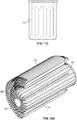
- FIGS. 7A-7C show a cylindrical filter element in which a filtration element 14 has been curved to extend around a cylinder axis that is aligned with the X direction (as shown in FIGS. 3 to 5 ).
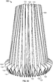
- FIGS. 8A-8C shows a cylindrical filter element for "liquid spin-on" applications, in which filtration element 14 has been curved to extend around a cylinder axis that is aligned with the Z direction (as shown in FIGS. 3 to 5 ).
- a standard pleated element 30 is depicted in the interior of the element 14.
- FIG. 13 is a top perspective view of the embodiment of FIGS. 8A-8C .
- FIG. 14 is a side view of the element of FIG. 13
- FIG. 15 is a bottom perspective view of the element of FIG. 13 .
- Another perspective view, with a partial section broken away, of the element of FIGS. 8A-8C and of FIGS. 13-15 is shown in FIG. 17 .
- FIG. 16 shows a scoring pattern to be applied to a sheet of filtration medium that is used to make the filter element of FIGS. 8A-8C , FIGS. 13-15 , and FIG. 17 .
- the heavy lines indicate a fold up, while the light lines indicate a fold down.
- FIGS. 9A-9C shows a cylindrical filter element in which a filtration element 14 has been curved to extend around a cylinder axis that is aligned with the Y direction (as shown in FIGS. 3 to 5 ).
- the filter element 14 is also sealed at its ends.
- FIGS. 10A-10C and 11A-11C show filter elements 14 in an obround, such as racetrack shape, and a rectangular pack configuration, respectively - each of which is sealed at its one end.
- FIGS. 12A-12C show a cylindrical filter element that is sealed at opposing ends.
- filter elements such as the obround element shown in FIG. 10 and the cylindrical element shown in FIG. 12 , where the folded pleats 17 need to be fanned out in a radial pattern, the number of major pleats is limited by the minor pleat density that is possible at the inside diameter of the radial formation. (If the minor pleat density gets too high on the inside, the filter media becomes masked.)
- the media density in the outer layers is limited by space (and thus medium density) constraints in the inner layers.
- This limitation can be offset by filling the inside of the filter element with conventionally pleated filtration media packs 24, in which the pleats are sealed on the inside at one end with hot melt adhesive 22, and sealed and secured to the adjacent outer folded pack at the other end by embedding the packs into an annular polymer end cap 23.
- FIG. 18 is a perspective view of a roll of media 32 during one step of making the filtration sheets of FIGS. 1, 2 , and 16 , but before a step of scoring.
- the media 32 has pleats folded at section 34, typically by a pleating machine. After the pleats are formed in section 34, the media at section 34 is scored.
- FIGS. 19 -21 show views of an example embodiment of a reciprocating scoring device 36 used on the media 32 to make the filtration sheets of FIGS. 1, 2 , and 16 .
- the scores are formed by the scoring device 36 after the pleats are formed, as depicted in FIG. 18 .
- the pressure drop across a filter element is related to the diameter of the outlet of the clean fluid exit hole, when you have filter elements that filter from outside to inside. It has been observed that the performance gains in a filter element rise (performance gains being defined by a decrease in pressure drop), as a ratio of the pleat depth to the diameter of the air outlet increases. It has further been observed that to achieve a longer filter life, more filter media is used, but as more filter media is used by way of increasing the pleat depth, the outlet hole becomes smaller. However, it has also been observed that to get better performance, as measured by less of a pressure drop, one wants to make the outlet size larger.
- the filter element 100 shown in FIG. 22 has been developed.
- the filter element 100 includes a pleated media pack 102.
- the pleated media pack 102 includes a section of filtration media folded into pleats 104. At least some of the pleats 104 have a major pleat depth 106 ( FIG. 34 ).
- the section of filtration media of the pleated media pack 102 can be configured into a tube defining an interior volume 108 ( FIG. 23 ).
- the pleated media pack 102 defines a first end 110 and an opposite second end 112.
- the interior volume 108 of the tube is shown as have a circular cross-section, but can have a variety of cross-sectional shapes including oval or racetrack. In the embodiment depicted, the interior volume 108 is conical in shape. In other embodiments, the interior volume 108 can be cylindrical in shape.
- FIG. 23 it can be seen how at the first end 110 is an opening 114 providing access to the interior volume 108.
- the opening 114 will act as the outlet opening 116 for the element 100. That is, fluid to be filtered will enter the element 100 from outside of the pleated media pack 102, pass through the pleats 104 and then into the interior volume 108. From the interior volume 108, the filtered fluid will exit through the outlet opening 116.
- the "diameter" of the opening 114 it refers to an outer diameter, if the opening 114 is generally circular. When not circular, the appropriate dimension is used.
- a ratio of the major pleat depth 106 to the dimension, such as outer diameter (if circular; in other shapes, the appropriate dimension is used) of the outlet opening 116 increases, performance gains of the preferred embodiment as compared to a typical prior art cylindrical element rise, which means the pressure drop decreases. It has been found that a ratio of the major pleat depth to the outer dimension, such as diameter, should be greater than 0.2 to achieve both performance and life advantages.
- the ratio of major pleat depth to outlet dimension should not exceed 0.5. When exceeding 0.5, in some filtering conditions, it can result in bunched up pleats.
- a first end 110 is secured to a first end cap 120, depicted schematically in the FIGS.
- the first end cap 120 seals the pleats 104 to prevent bypass of filter flow. More details on the first end cap 120 are described further below.
- a second end cap 122 is secured to the pleats 104 to close the ends.
- the second end cap 122 can either be a closed end cap or an open end cap.
- the pleats 104 include major pleats 124 defining the major pleat depth 106.
- the pleats 104 in example embodiment illustrated, includes minor pleats 126.
- the minor pleats 126 have a minor pleat depth 128 ( FIG. 34 ) that is less than the major pleat depth 106.
- the pleated media pack 102 is illustrated before being formed into the element 100 having end caps 120, 122.
- the pleated media pack 102 is configured to increase size of the fluid flow outlet, being formed at the opening 114 ( FIGS. 23 and 24 ), which results in performance improvement (less pressure drop across the media pack 102).
- the pleated media pack 102 is configured to increase size of the fluid flow outlet, being formed at the opening 114 ( FIGS. 23 and 24 ), which results in performance improvement (less pressure drop across the media pack 102).
- at least some of the pleats 104 at the first end 110 are inverted an opposite direction of the remaining portion, or rest, of the pleat 104.
- the inverted section 132 extends from the first end 110 along at least a portion of the pleat length from the first end 110 to the second end 112.
- the inverted section 132 extends from the first end 110 not greater than 50% of the length to the second end 112. In some implementations, the inverted section 132 extends from the first end 110 at least 5% of the length to the second end 112. In some implementations, the inverted section 132 extends from the first end 110 between 10%-30% of the length to the second end 112.
- the inverted sections 132 appear as triangular extensions 134 of media projecting from a remaining portion of the pleated media pack 102.
- At least some of the major pleats 124 at the first end 110 are inverted at section 135 ( FIG. 33 ) in an opposite direction of the rest of the pleat 104.
- At least some of the minor pleats 126 at the first end 110 are inverted at section 137 ( FIG. 33 ) an opposite direction of the rest of the pleat 104.
- both the major pleats 124 and minor pleats 126 at the first end 110 are inverted at sections 135, 137, respectively, in an opposite direction of the rest of the pleat 104, along at least a portion of the pleat length from the first end 110 toward the second end 112.
- all of the major pleats 124 and minor pleats 126 at the first end 110 are inverted an opposite direction of the rest of the pleat 104, along at least a portion of the pleat length from the first end 110 toward the second end 112.
- the second end 112 preferably will not include inverted sections 132, but will be the normal pleat folded direction.
- an outer profile shape of the media pack 102 can be generally conical, with an inner diameter at the first end 110 being greater than an inner diameter at the second end 112.
- the outer profile shape of the media pack 102 can be generally cylindrical, in which the inner diameter at the first end 110 is general equal to the inner diameter at the second end 112.
- the first end cap 120 is shown schematically, and schematically represents a section of a potting compound 136, or urethane material, that can be used to seal the media pack 102 along the radial outer periphery of the pleated media pack 102. This includes the inverted sections 132 of the pleats 104.
- the first end cap 120 can be made by using a centrifugal control for the potting compound 136.
- the centrifugal control to apply the potting compound 136 results in at least two benefits.
- the first benefit is that not as much potting compound 136 is needed, as compared to processes that use a free rise molding technique.
- the second benefit is that not as much filter media is masked through the centrifugal control, as compared to molding in a free rise molding process.
- FIGS. 26-30 illustrate a media sheet 140 before it is formed into the pleated media pack 102.
- FIG. 26 shows a flattened piece of media sheet 140 with the scoring pattern.
- the solid lines illustrate fold lines that are folded upwardly and out of the paper, while the broken lines illustrate fold lines that are folded downwardly or into the paper.
- the fold lines 142 form the major pleats 124, while the fold lines 144 form the minor pleats 126.
- the diagonal fold lines 148 form the inverted sections 135 for the major pleats 124.
- the diagonal fold lines 150 form the inverted sections 137 for the minor pleats 126.
- FIG. 27 is a top view of the media sheet 140 folded along the score lines of FIG. 26 , and before the media sheet 140 is formed into the pleated media pack 102.
- FIG. 28 is a perspective view of the media sheet 140 of FIG. 27 .
- FIGS. 29 and 30 show opposite end views of the media sheet 140 of FIGS. 27 and 28 .
- the media sheet 140 can be cellulose with or without fine fiber. Many variations can be used.
- the element 100 can also be constructed using the media described in connection with FIGS. 1-21 , above, folded to have: a major pleated structure comprising inclined walls that are connected continuously at generally parallel alternating major pleats, said major pleats extending along opposing edges of each inclined wall and said major pleats protruding towards opposing sides of the sheet in alternating fashion; a minor pleated structure formed in each of the inclined walls of the major pleated structure, with alternating minor pleats formed in each of said inclined walls, each of said minor pleats protruding towards opposing sides of the sheet in alternating fashion and each of said minor pleats extending transversely between the major pleats at opposing edges of the inclined wall, with minor pleats of adjacent inclined walls being generally aligned on opposing sides of each major pleat; and indentations formed along each major pleat, each indentation comprising two triangles on opposing sides of a common base line, said base line extending between and being aligned with two minor pleats, said minor pleats being on
Claims (13)
- Plissiertes Medienpaket (102) zur Verwendung in einem Filterelement (100); wobei das Medienpaket (102) aufweist:(a) einen Abschnitt von zu Falten gefalteten Filtermedien (104); zumindest einige der Falten haben eine größere Faltentiefe (106);(b) wobei der Abschnitt der Filtermedien zu einem Rohr konfiguriert ist, das ein Innenvolumen (108), ein erstes (110) und ein zweites (112) entgegengesetzte Ende und eine Öffnung (114) am ersten Ende (110) definiert, wobei die Öffnung einen Durchmesser aufweist;dadurch gekennzeichnet, dass ein Verhältnis der Faltentiefe zum Öffnungsdurchmesser größer als 0,2 ist;
und dass mindestens einige der Falten am ersten Ende (110) in einer entgegengesetzten Richtung zum Rest der Falte umgedreht (132) sind, wobei sich die umgedrehten Abschnitte (132) vom ersten Ende (110) entlang mindestens eines Teils der Faltenlänge vom ersten Ende (110) zum zweiten Ende (112) erstrecken, wobei die umgedrehten Abschnitte (132) als Verlängerungen (134) von Medien erscheinen, die sich von einem verbleibenden Teil des Medienpakets (102) erstrecken und radial außerhalb von diesem befinden. - Medienpaket (102) nach Anspruch 1, wobei das Verhältnis nicht größer als 0,5 ist.
- Medienpaket (102) nach einem der Ansprüche 1 und 2, wobei das Verhältnis zwischen 0,2 und 0,35 liegt.
- Medienpaket (102) nach einem der Ansprüche 1-3, wobei die Falten Hauptfalten (124), die die größere Faltentiefe definieren, und Nebenfalten (126) mit einer kleineren Faltentiefe, die geringer ist als die Hauptfaltentiefe, enthalten.
- Medienpaket (102) nach Anspruch 4, wobei sich die Hauptfalten (124) und die Nebenfalten (126) abwechseln.
- Medienpaket (102) nach einem der Ansprüche 4 und 5, wobei mindestens einige der Hauptfalten (124) am ersten Ende (110) in entgegengesetzter Richtung zum Rest der Falte entlang mindestens eines Teils der Faltenlänge vom ersten Ende (110) zum zweiten Ende (112) umgedreht sind.
- Medienpaket (102) nach einem der Ansprüche 4 und 5, wobei mindestens einige der Nebenfalten (126) am ersten Ende (110) entlang mindestens eines Teils der Faltenlänge vom ersten Ende (110) zum zweiten Ende (112) in entgegengesetzter Richtung zum Rest der Falte umgedreht sind.
- Medienpaket (102) nach einem der Ansprüche 4 und 5, wobei die Hauptfalten (124) und die Nebenfalten (126) am ersten Ende (110) entlang mindestens eines Teils der Faltenlänge vom ersten Ende (110) zum zweiten Ende (112) in entgegengesetzter Richtung zum Rest der Falte umgedreht sind.
- Medienpaket (102) nach einem der Ansprüche 1-8, wobei eine äußere Profilform der Medienpackung (102) allgemein konisch ist, mit einem Durchmesser am ersten Ende (110), der größer ist als ein Durchmesser am zweiten Ende (112).
- Medienpaket (102) nach Anspruch 1, wobei der Abschnitt des Filtrationsmediums gefaltet ist, um zu bilden: eine größere gefaltete Struktur mit geneigten Wänden, die kontinuierlich an im allgemeinen parallel abwechselnden Hauptfalten verbunden sind, wobei sich die Hauptfalten entlang gegenüberliegender Kanten jeder geneigten Wand erstrecken und die Hauptfalten abwechselnd zu gegenüberliegenden Seiten des Blattes vorstehen; eine kleinere gefaltete Struktur, die in jeder der geneigten Wände der größeren gefalteten Struktur gebildet ist, wobei abwechselnde Nebenfalten in jeder der geneigten Wände gebildet sind, wobei jede der Nebenfalten abwechselnd zu gegenüberliegenden Seiten des Blattes vorstehen und sich jede der Nebenfalten quer zwischen den Hauptfalten an gegenüberliegenden Rändern der geneigten Wand erstreckt, wobei Nebenfalten benachbarter geneigter Wände im Allgemeinen auf gegenüberliegenden Seiten jeder Hauptfalte ausgerichtet sind; und Einbuchtungen, gebildet entlang jeder Hauptfalte, wobei jede Einkerbung zwei Dreiecke auf gegenüberliegenden Seiten einer gemeinsamen Grundlinie umfasst, wobei sich die Grundlinie zwischen zwei Nebenfalten erstreckt und mit diesen ausgerichtet ist, wobei sich die Nebenfalten auf gegenüberliegenden Seiten der Hauptfalte befinden und die Nebenfalten in Richtung derselben Seite des Blattes wie die Hauptfalte hervorstehen, und der Scheitelpunkt jedes der beiden Dreiecke an der Verbindungsstelle von zwei ausgerichteten Nebenfalten liegt, die in Richtung der Seite des Blattes hervorstehen, die der Seite, zu der die Hauptfalte vorsteht, gegenüber liegt.
- Filterelement (100), umfassend ein Medienpaket nach einem der Ansprüche 1-10, wobei das Filterelement umfasst:(a) eine erste offene Endkappe (120), die am ersten Ende (110) des Medienpakets (102) befestigt ist; und(b) eine zweite Endkappe (122), die am zweiten Ende (112) des Medienpakets (102) befestigt ist.
- Filterelement (100) nach Anspruch 11, wobei die zweite Endkappe (122) eine geschlossene Endkappe ist.
- Filterelement (100) nach einem der Ansprüche 11 und 12, wobei die erste offene Endkappe (120) eine Auslassöffnung (116) für einen Austritt von gefiltertem Fluid definiert.
Applications Claiming Priority (2)
| Application Number | Priority Date | Filing Date | Title |
|---|---|---|---|
| ZA201207631 | 2012-10-09 | ||
| PCT/US2013/064124 WO2014059014A1 (en) | 2012-10-09 | 2013-10-09 | Self-supporting folder sheet material, filter elements, and methods |
Publications (2)
| Publication Number | Publication Date |
|---|---|
| EP2906320A1 EP2906320A1 (de) | 2015-08-19 |
| EP2906320B1 true EP2906320B1 (de) | 2020-08-26 |
Family
ID=49486687
Family Applications (1)
| Application Number | Title | Priority Date | Filing Date |
|---|---|---|---|
| EP13783164.0A Active EP2906320B1 (de) | 2012-10-09 | 2013-10-09 | Selbsttragendes gefaltetes blattmaterial, filterelemente |
Country Status (5)
| Country | Link |
|---|---|
| US (1) | US10112130B2 (de) |
| EP (1) | EP2906320B1 (de) |
| CN (2) | CN104822432B (de) |
| WO (1) | WO2014059014A1 (de) |
| ZA (1) | ZA201503154B (de) |
Families Citing this family (20)
| Publication number | Priority date | Publication date | Assignee | Title |
|---|---|---|---|---|
| US10112130B2 (en) | 2012-10-09 | 2018-10-30 | Donaldson Company, Inc. | Self-supporting folded sheet material, filter elements, and methods |
| CN106132507A (zh) * | 2014-04-09 | 2016-11-16 | 唐纳森公司 | 自承式折叠的片材材料以及过滤元件 |
| US9440178B2 (en) * | 2014-06-23 | 2016-09-13 | Caterpillar Inc. | Pleated filter media |
| DE102014019474A1 (de) * | 2014-12-23 | 2016-06-23 | Mann + Hummel Gmbh | Faltenbalg für ein Filterelement und Filterelement |
| EP3156115A1 (de) | 2015-10-13 | 2017-04-19 | Mann + Hummel Gmbh | Filterelement mit einem plissierten filterkörper und einem filtersystem |
| US11040302B2 (en) * | 2016-02-25 | 2021-06-22 | Cummins Filtration Ip, Inc. | Folded filter media pack with varying channels and deep corrugations |
| US11400405B2 (en) * | 2016-07-13 | 2022-08-02 | Cummins Filtration Ip, Inc. | Filter element with tapered perimeter |
| TWI627993B (zh) * | 2016-08-19 | 2018-07-01 | 財團法人金屬工業研究發展中心 | 除塵裝置、集塵器及集塵器的清潔方法 |
| US11439943B2 (en) | 2016-10-20 | 2022-09-13 | Cummins Filtration Ip, Inc. | Interrupted, directional emboss of flat sheet |
| WO2018111822A1 (en) | 2016-12-15 | 2018-06-21 | Cummins Filtration Ip, Inc. | Tetrahedral filter media |
| WO2018191147A1 (en) | 2017-04-11 | 2018-10-18 | Cummins Filtration Ip, Inc. | Panel filter element |
| DE102017003577A1 (de) | 2017-04-12 | 2018-10-18 | Hydac Process Technology Gmbh | Vorrichtung zum Behandeln von Fluid |
| AU2018335572B2 (en) | 2017-09-25 | 2023-12-14 | Donaldson Company, Inc. | Filter assembly |
| KR102619773B1 (ko) * | 2018-03-08 | 2024-01-02 | 쓰리엠 이노베이티브 프로퍼티즈 캄파니 | 필터 및 이를 포함하는 마스크 |
| JP6727244B2 (ja) * | 2018-04-11 | 2020-07-22 | 和興フィルタテクノロジー株式会社 | エアフィルタ |
| US10773198B2 (en) * | 2018-10-24 | 2020-09-15 | Pall Corporation | Support and drainage material, filter, and method of use |
| EP3646934A1 (de) * | 2018-11-05 | 2020-05-06 | Carl Freudenberg KG | Filterelement mit gegenfaltung und kassettenfilter mit solchen filterelementen und filterpatrone mit einem solchen filterelement |
| BR112021018914A2 (pt) | 2019-03-27 | 2021-11-30 | Donaldson Co Inc | Filtro separador de partículas com uma face de fluxo que se estende axialmente |
| US20210170311A1 (en) * | 2019-12-09 | 2021-06-10 | Pall Corporation | Filter element, filter, filter device, and method of use |
| JP2020089888A (ja) * | 2020-02-20 | 2020-06-11 | 和興フィルタテクノロジー株式会社 | エアフィルタ |
Citations (5)
| Publication number | Priority date | Publication date | Assignee | Title |
|---|---|---|---|---|
| FR795282A (fr) * | 1934-12-12 | 1936-03-10 | A Gouet Ets | Perfectionnements aux filtres à gaz |
| DE9010910U1 (de) * | 1990-07-23 | 1990-10-25 | Electrostar Schoettle Gmbh & Co, 7313 Reichenbach, De | |
| US5128039A (en) * | 1991-06-04 | 1992-07-07 | Allied-Signal Inc. | Filter with delta wedge pleat |
| US5522909A (en) * | 1994-12-27 | 1996-06-04 | Purolator Products Na, Inc. | Air filter device |
| DE19849998A1 (de) * | 1998-10-30 | 2000-05-04 | Mann & Hummel Filter | Filter |
Family Cites Families (46)
| Publication number | Priority date | Publication date | Assignee | Title |
|---|---|---|---|---|
| US3124441A (en) | 1964-03-10 | Pocicet-type | ||
| US2556521A (en) | 1946-11-14 | 1951-06-12 | Fram Corp | Filter element |
| US2683537A (en) | 1949-06-11 | 1954-07-13 | Fram Corp | Pleated filter element |
| US2862624A (en) | 1954-04-21 | 1958-12-02 | Vokes Ltd | Filter elements |
| US2980208A (en) | 1957-05-21 | 1961-04-18 | Delbag Luftfilter Gmbh | Filter element for extremely fine dust |
| US2936855A (en) | 1957-10-23 | 1960-05-17 | Gen Motors Corp | Pleated filter and mechanism for forming same |
| US3058594A (en) | 1960-06-06 | 1962-10-16 | Purolator Products Inc | Pleated paper filter |
| FR1288229A (fr) * | 1961-02-10 | 1962-03-24 | Fr De L Acetylene Soc | Filtre à plusieurs nappes filtrantes |
| US3386232A (en) | 1965-04-22 | 1968-06-04 | American Air Filter Co | Pocket-type filter |
| US3401803A (en) | 1965-12-06 | 1968-09-17 | Mine Safety Appliances Co | Filter formed from corrugated and flat sheets |
| US3440807A (en) | 1966-02-01 | 1969-04-29 | American Air Filter Co | Pocket-type filter cartridge and support structure assembly |
| US3410062A (en) | 1966-09-12 | 1968-11-12 | Cambridge Filter Corp | Filter |
| US3531920A (en) | 1968-09-16 | 1970-10-06 | Cambridge Filter Corp | Filter |
| US3640396A (en) | 1970-04-03 | 1972-02-08 | Fram Corp | Filter |
| FR2267818B1 (de) | 1974-04-16 | 1976-12-17 | Labinal | |
| FR2273657A1 (fr) | 1974-06-06 | 1976-01-02 | Gewiss Lucien | Machine pour le faconnage de structures plissees en chevrons |
| AU565494B2 (en) | 1983-10-18 | 1987-09-17 | Nippondenso Co. Ltd. | Filter element |
| FR2568138B1 (fr) | 1984-07-25 | 1986-11-14 | Are Sarl | Cartouche de filtration a surface externe en nids d'abeilles et procede de realisation |
| US4710297A (en) | 1985-06-15 | 1987-12-01 | Kabushiki Kaisha Tsuchiya Seisakusho | Fluid filter with pleated filter medium |
| US4673503A (en) | 1985-07-18 | 1987-06-16 | Tokyo Roki Co., Ltd. | Variant length pleated filter element |
| US4925561A (en) | 1988-03-31 | 1990-05-15 | Tsuchiya Mfg. Co., Ltd. | Composite planar and triangularly pleated filter element |
| TW199108B (de) | 1991-11-11 | 1993-02-01 | British United Shoe Machinery | |
| US5306321A (en) | 1992-07-07 | 1994-04-26 | Donaldson Company, Inc. | Layered air filter medium having improved efficiency and pleatability |
| JPH0679836A (ja) | 1992-09-03 | 1994-03-22 | Hitachi Chem Co Ltd | 積層シート状成形材料及びそれを用いた成形品の製造法 |
| US5320657A (en) * | 1993-04-30 | 1994-06-14 | Dana Corporation | Staggered short pleat air filter |
| DE4345130C1 (de) | 1993-12-30 | 2000-11-23 | Jacobi Systemtechnik Gmbh | Hohlzylindrisches Filterelement |
| US5632792A (en) * | 1995-08-16 | 1997-05-27 | Purolator Products Company | Air induction filter hose assembly |
| US5804073A (en) | 1996-07-22 | 1998-09-08 | Ter Horst; Dirk Dieter Hans | Method of making a pleated structure having a pleated memory shape and the filter media made therefrom |
| EP1595590A1 (de) * | 1999-01-07 | 2005-11-16 | Cuno Incorporated | Gefaltetes Filterelement und Verfahren zur Herstellung eines gefalteten Filterelements |
| JP5042408B2 (ja) | 1999-01-07 | 2012-10-03 | スリーエム イノベーティブ プロパティーズ カンパニー | プリーツ付フィルター要素 |
| SE521922C2 (sv) * | 1999-03-29 | 2003-12-16 | Johann Haberl | Filterpatron som är lämpad för användning i utloppet i en centrifugalseparator |
| FR2791579A1 (fr) * | 1999-04-02 | 2000-10-06 | Albrecht Philippe | Cartouche filtrante demontable et recyclable pour filtres a liquide immerges |
| DE10049980C2 (de) | 2000-10-06 | 2002-09-05 | Freudenberg Carl Kg | Gefalteter räumlicher Gegenstand insbesondere Filterelement, sowie Verfahren und Vorrichtung zu seiner Herstellung |
| US6416561B1 (en) | 2000-10-20 | 2002-07-09 | Nelson Industries, Inc. | Open flow filter with safety element |
| US6585793B2 (en) | 2000-12-29 | 2003-07-01 | Andreae Filters, Inc. | Filter apparatus and methods |
| US6824581B1 (en) | 2001-05-01 | 2004-11-30 | Dana Corporation | Pleated filter media with embossed spacers and cross flow |
| ATE372162T1 (de) * | 2002-10-28 | 2007-09-15 | Donaldson Co Inc | Luftfilter; auswechselbare filterpatrone; und verfahren |
| US7311747B2 (en) | 2003-10-14 | 2007-12-25 | Donaldson Company, Inc. | Filter assembly with pleated media V-packs, and methods |
| KR20070000513A (ko) | 2004-04-15 | 2007-01-02 | 엔테그리스, 아이엔씨. | 플리츠형 카트리지 필터 장치 |
| US20060151383A1 (en) | 2005-01-12 | 2006-07-13 | Aaf-Mcquay Inc. | Pleated corrugated media and method of making |
| JP2009083668A (ja) | 2007-09-28 | 2009-04-23 | Valeo Thermal Systems Japan Corp | フィルタ装置及びそれを用いた自動車用空調装置 |
| DE102009051987A1 (de) * | 2009-11-05 | 2011-05-12 | Valeo Klimasysteme Gmbh | Filterbaugruppe einer Fahrzeugheizungs- oder -klima-anlage, Filtereinheit hierfür und Verfahren zur Herstellung der Filterbaugruppe |
| CN105536383B (zh) | 2010-01-25 | 2019-12-24 | 唐纳森公司 | 具有楔形槽的褶状过滤介质 |
| CN201823417U (zh) * | 2010-07-30 | 2011-05-11 | 山东开泰抛丸机械有限公司 | 一种用于滤筒式除尘器上的滤筒 |
| US10112130B2 (en) | 2012-10-09 | 2018-10-30 | Donaldson Company, Inc. | Self-supporting folded sheet material, filter elements, and methods |
| CN106132507A (zh) | 2014-04-09 | 2016-11-16 | 唐纳森公司 | 自承式折叠的片材材料以及过滤元件 |
-
2013
- 2013-10-09 US US14/433,980 patent/US10112130B2/en active Active
- 2013-10-09 CN CN201380056677.0A patent/CN104822432B/zh active Active
- 2013-10-09 WO PCT/US2013/064124 patent/WO2014059014A1/en active Application Filing
- 2013-10-09 EP EP13783164.0A patent/EP2906320B1/de active Active
- 2013-10-09 CN CN201710371871.8A patent/CN107321025B/zh active Active
-
2015
- 2015-05-08 ZA ZA2015/03154A patent/ZA201503154B/en unknown
Patent Citations (5)
| Publication number | Priority date | Publication date | Assignee | Title |
|---|---|---|---|---|
| FR795282A (fr) * | 1934-12-12 | 1936-03-10 | A Gouet Ets | Perfectionnements aux filtres à gaz |
| DE9010910U1 (de) * | 1990-07-23 | 1990-10-25 | Electrostar Schoettle Gmbh & Co, 7313 Reichenbach, De | |
| US5128039A (en) * | 1991-06-04 | 1992-07-07 | Allied-Signal Inc. | Filter with delta wedge pleat |
| US5522909A (en) * | 1994-12-27 | 1996-06-04 | Purolator Products Na, Inc. | Air filter device |
| DE19849998A1 (de) * | 1998-10-30 | 2000-05-04 | Mann & Hummel Filter | Filter |
Also Published As
| Publication number | Publication date |
|---|---|
| WO2014059014A1 (en) | 2014-04-17 |
| CN104822432A (zh) | 2015-08-05 |
| CN104822432B (zh) | 2017-06-20 |
| CN107321025B (zh) | 2019-07-09 |
| WO2014059014A8 (en) | 2015-05-14 |
| EP2906320A1 (de) | 2015-08-19 |
| US20150251111A1 (en) | 2015-09-10 |
| US10112130B2 (en) | 2018-10-30 |
| CN107321025A (zh) | 2017-11-07 |
| ZA201503154B (en) | 2016-09-28 |
Similar Documents
| Publication | Publication Date | Title |
|---|---|---|
| EP2906320B1 (de) | Selbsttragendes gefaltetes blattmaterial, filterelemente | |
| KR102331811B1 (ko) | 여과 매체, 주름형 매체 팩, 필터 카트리지, 및 제조 방법 | |
| EP3218080B1 (de) | Filtermedienpackungen mit mehreren bossen zwischen filtermedien, filterelemente und verfahren zur herstellung | |
| CN107135648A (zh) | 具有突出部的过滤介质、过滤包以及过滤器元件 | |
| EP2959955B1 (de) | Spiralförmig gewickelter filter | |
| WO2005082484A1 (en) | Pleated corrugated filter media | |
| US10675580B1 (en) | Air filtration with a V-bank filter apparatus and method | |
| CN115155188A (zh) | 自承式折叠的片材材料以及过滤元件 | |
| EP3129636B1 (de) | Filtermedienkonstruktion | |
| CN107847845B (zh) | 耐高压过滤器 | |
| CN114423508B (zh) | 管状的褶折式过滤器部件 | |
| EP3156115A1 (de) | Filterelement mit einem plissierten filterkörper und einem filtersystem | |
| WO2005082485A1 (en) | Media support screen arrangement for liquid filters | |
| EP3976225B1 (de) | Gekrümmter kern für variablen faltenfilter | |
| WO2023021336A2 (en) | Radial pleats for a filter | |
| CS243385B1 (cs) | Filtr pro tekutiny ze spirálovitá stočeného filtračního pásu |
Legal Events
| Date | Code | Title | Description |
|---|---|---|---|
| PUAI | Public reference made under article 153(3) epc to a published international application that has entered the european phase |
Free format text: ORIGINAL CODE: 0009012 |
|
| 17P | Request for examination filed |
Effective date: 20150511 |
|
| AK | Designated contracting states |
Kind code of ref document: A1 Designated state(s): AL AT BE BG CH CY CZ DE DK EE ES FI FR GB GR HR HU IE IS IT LI LT LU LV MC MK MT NL NO PL PT RO RS SE SI SK SM TR |
|
| AX | Request for extension of the european patent |
Extension state: BA ME |
|
| DAX | Request for extension of the european patent (deleted) | ||
| STAA | Information on the status of an ep patent application or granted ep patent |
Free format text: STATUS: EXAMINATION IS IN PROGRESS |
|
| 17Q | First examination report despatched |
Effective date: 20171218 |
|
| GRAP | Despatch of communication of intention to grant a patent |
Free format text: ORIGINAL CODE: EPIDOSNIGR1 |
|
| STAA | Information on the status of an ep patent application or granted ep patent |
Free format text: STATUS: GRANT OF PATENT IS INTENDED |
|
| INTG | Intention to grant announced |
Effective date: 20200309 |
|
| GRAS | Grant fee paid |
Free format text: ORIGINAL CODE: EPIDOSNIGR3 |
|
| GRAA | (expected) grant |
Free format text: ORIGINAL CODE: 0009210 |
|
| STAA | Information on the status of an ep patent application or granted ep patent |
Free format text: STATUS: THE PATENT HAS BEEN GRANTED |
|
| AK | Designated contracting states |
Kind code of ref document: B1 Designated state(s): AL AT BE BG CH CY CZ DE DK EE ES FI FR GB GR HR HU IE IS IT LI LT LU LV MC MK MT NL NO PL PT RO RS SE SI SK SM TR |
|
| REG | Reference to a national code |
Ref country code: GB Ref legal event code: FG4D |
|
| REG | Reference to a national code |
Ref country code: CH Ref legal event code: EP |
|
| REG | Reference to a national code |
Ref country code: AT Ref legal event code: REF Ref document number: 1305814 Country of ref document: AT Kind code of ref document: T Effective date: 20200915 |
|
| REG | Reference to a national code |
Ref country code: IE Ref legal event code: FG4D |
|
| REG | Reference to a national code |
Ref country code: DE Ref legal event code: R096 Ref document number: 602013071982 Country of ref document: DE |
|
| REG | Reference to a national code |
Ref country code: LT Ref legal event code: MG4D |
|
| PG25 | Lapsed in a contracting state [announced via postgrant information from national office to epo] |
Ref country code: SE Free format text: LAPSE BECAUSE OF FAILURE TO SUBMIT A TRANSLATION OF THE DESCRIPTION OR TO PAY THE FEE WITHIN THE PRESCRIBED TIME-LIMIT Effective date: 20200826 Ref country code: GR Free format text: LAPSE BECAUSE OF FAILURE TO SUBMIT A TRANSLATION OF THE DESCRIPTION OR TO PAY THE FEE WITHIN THE PRESCRIBED TIME-LIMIT Effective date: 20201127 Ref country code: LT Free format text: LAPSE BECAUSE OF FAILURE TO SUBMIT A TRANSLATION OF THE DESCRIPTION OR TO PAY THE FEE WITHIN THE PRESCRIBED TIME-LIMIT Effective date: 20200826 Ref country code: BG Free format text: LAPSE BECAUSE OF FAILURE TO SUBMIT A TRANSLATION OF THE DESCRIPTION OR TO PAY THE FEE WITHIN THE PRESCRIBED TIME-LIMIT Effective date: 20201126 Ref country code: PT Free format text: LAPSE BECAUSE OF FAILURE TO SUBMIT A TRANSLATION OF THE DESCRIPTION OR TO PAY THE FEE WITHIN THE PRESCRIBED TIME-LIMIT Effective date: 20201228 Ref country code: HR Free format text: LAPSE BECAUSE OF FAILURE TO SUBMIT A TRANSLATION OF THE DESCRIPTION OR TO PAY THE FEE WITHIN THE PRESCRIBED TIME-LIMIT Effective date: 20200826 Ref country code: FI Free format text: LAPSE BECAUSE OF FAILURE TO SUBMIT A TRANSLATION OF THE DESCRIPTION OR TO PAY THE FEE WITHIN THE PRESCRIBED TIME-LIMIT Effective date: 20200826 Ref country code: NO Free format text: LAPSE BECAUSE OF FAILURE TO SUBMIT A TRANSLATION OF THE DESCRIPTION OR TO PAY THE FEE WITHIN THE PRESCRIBED TIME-LIMIT Effective date: 20201126 |
|
| REG | Reference to a national code |
Ref country code: NL Ref legal event code: MP Effective date: 20200826 |
|
| REG | Reference to a national code |
Ref country code: AT Ref legal event code: MK05 Ref document number: 1305814 Country of ref document: AT Kind code of ref document: T Effective date: 20200826 |
|
| PG25 | Lapsed in a contracting state [announced via postgrant information from national office to epo] |
Ref country code: LV Free format text: LAPSE BECAUSE OF FAILURE TO SUBMIT A TRANSLATION OF THE DESCRIPTION OR TO PAY THE FEE WITHIN THE PRESCRIBED TIME-LIMIT Effective date: 20200826 Ref country code: NL Free format text: LAPSE BECAUSE OF FAILURE TO SUBMIT A TRANSLATION OF THE DESCRIPTION OR TO PAY THE FEE WITHIN THE PRESCRIBED TIME-LIMIT Effective date: 20200826 Ref country code: RS Free format text: LAPSE BECAUSE OF FAILURE TO SUBMIT A TRANSLATION OF THE DESCRIPTION OR TO PAY THE FEE WITHIN THE PRESCRIBED TIME-LIMIT Effective date: 20200826 Ref country code: PL Free format text: LAPSE BECAUSE OF FAILURE TO SUBMIT A TRANSLATION OF THE DESCRIPTION OR TO PAY THE FEE WITHIN THE PRESCRIBED TIME-LIMIT Effective date: 20200826 Ref country code: IS Free format text: LAPSE BECAUSE OF FAILURE TO SUBMIT A TRANSLATION OF THE DESCRIPTION OR TO PAY THE FEE WITHIN THE PRESCRIBED TIME-LIMIT Effective date: 20201226 |
|
| PG25 | Lapsed in a contracting state [announced via postgrant information from national office to epo] |
Ref country code: EE Free format text: LAPSE BECAUSE OF FAILURE TO SUBMIT A TRANSLATION OF THE DESCRIPTION OR TO PAY THE FEE WITHIN THE PRESCRIBED TIME-LIMIT Effective date: 20200826 Ref country code: CZ Free format text: LAPSE BECAUSE OF FAILURE TO SUBMIT A TRANSLATION OF THE DESCRIPTION OR TO PAY THE FEE WITHIN THE PRESCRIBED TIME-LIMIT Effective date: 20200826 Ref country code: DK Free format text: LAPSE BECAUSE OF FAILURE TO SUBMIT A TRANSLATION OF THE DESCRIPTION OR TO PAY THE FEE WITHIN THE PRESCRIBED TIME-LIMIT Effective date: 20200826 Ref country code: SM Free format text: LAPSE BECAUSE OF FAILURE TO SUBMIT A TRANSLATION OF THE DESCRIPTION OR TO PAY THE FEE WITHIN THE PRESCRIBED TIME-LIMIT Effective date: 20200826 Ref country code: RO Free format text: LAPSE BECAUSE OF FAILURE TO SUBMIT A TRANSLATION OF THE DESCRIPTION OR TO PAY THE FEE WITHIN THE PRESCRIBED TIME-LIMIT Effective date: 20200826 |
|
| REG | Reference to a national code |
Ref country code: DE Ref legal event code: R097 Ref document number: 602013071982 Country of ref document: DE |
|
| PG25 | Lapsed in a contracting state [announced via postgrant information from national office to epo] |
Ref country code: AT Free format text: LAPSE BECAUSE OF FAILURE TO SUBMIT A TRANSLATION OF THE DESCRIPTION OR TO PAY THE FEE WITHIN THE PRESCRIBED TIME-LIMIT Effective date: 20200826 Ref country code: AL Free format text: LAPSE BECAUSE OF FAILURE TO SUBMIT A TRANSLATION OF THE DESCRIPTION OR TO PAY THE FEE WITHIN THE PRESCRIBED TIME-LIMIT Effective date: 20200826 Ref country code: ES Free format text: LAPSE BECAUSE OF FAILURE TO SUBMIT A TRANSLATION OF THE DESCRIPTION OR TO PAY THE FEE WITHIN THE PRESCRIBED TIME-LIMIT Effective date: 20200826 |
|
| REG | Reference to a national code |
Ref country code: CH Ref legal event code: PL |
|
| PG25 | Lapsed in a contracting state [announced via postgrant information from national office to epo] |
Ref country code: LU Free format text: LAPSE BECAUSE OF NON-PAYMENT OF DUE FEES Effective date: 20201009 Ref country code: SK Free format text: LAPSE BECAUSE OF FAILURE TO SUBMIT A TRANSLATION OF THE DESCRIPTION OR TO PAY THE FEE WITHIN THE PRESCRIBED TIME-LIMIT Effective date: 20200826 Ref country code: MC Free format text: LAPSE BECAUSE OF FAILURE TO SUBMIT A TRANSLATION OF THE DESCRIPTION OR TO PAY THE FEE WITHIN THE PRESCRIBED TIME-LIMIT Effective date: 20200826 |
|
| PLBE | No opposition filed within time limit |
Free format text: ORIGINAL CODE: 0009261 |
|
| STAA | Information on the status of an ep patent application or granted ep patent |
Free format text: STATUS: NO OPPOSITION FILED WITHIN TIME LIMIT |
|
| REG | Reference to a national code |
Ref country code: BE Ref legal event code: MM Effective date: 20201031 |
|
| PG25 | Lapsed in a contracting state [announced via postgrant information from national office to epo] |
Ref country code: IT Free format text: LAPSE BECAUSE OF FAILURE TO SUBMIT A TRANSLATION OF THE DESCRIPTION OR TO PAY THE FEE WITHIN THE PRESCRIBED TIME-LIMIT Effective date: 20200826 |
|
| 26N | No opposition filed |
Effective date: 20210527 |
|
| PG25 | Lapsed in a contracting state [announced via postgrant information from national office to epo] |
Ref country code: CH Free format text: LAPSE BECAUSE OF NON-PAYMENT OF DUE FEES Effective date: 20201031 Ref country code: BE Free format text: LAPSE BECAUSE OF NON-PAYMENT OF DUE FEES Effective date: 20201031 Ref country code: SI Free format text: LAPSE BECAUSE OF FAILURE TO SUBMIT A TRANSLATION OF THE DESCRIPTION OR TO PAY THE FEE WITHIN THE PRESCRIBED TIME-LIMIT Effective date: 20200826 Ref country code: LI Free format text: LAPSE BECAUSE OF NON-PAYMENT OF DUE FEES Effective date: 20201031 |
|
| PG25 | Lapsed in a contracting state [announced via postgrant information from national office to epo] |
Ref country code: IE Free format text: LAPSE BECAUSE OF NON-PAYMENT OF DUE FEES Effective date: 20201009 |
|
| PG25 | Lapsed in a contracting state [announced via postgrant information from national office to epo] |
Ref country code: TR Free format text: LAPSE BECAUSE OF FAILURE TO SUBMIT A TRANSLATION OF THE DESCRIPTION OR TO PAY THE FEE WITHIN THE PRESCRIBED TIME-LIMIT Effective date: 20200826 Ref country code: MT Free format text: LAPSE BECAUSE OF FAILURE TO SUBMIT A TRANSLATION OF THE DESCRIPTION OR TO PAY THE FEE WITHIN THE PRESCRIBED TIME-LIMIT Effective date: 20200826 Ref country code: CY Free format text: LAPSE BECAUSE OF FAILURE TO SUBMIT A TRANSLATION OF THE DESCRIPTION OR TO PAY THE FEE WITHIN THE PRESCRIBED TIME-LIMIT Effective date: 20200826 |
|
| PG25 | Lapsed in a contracting state [announced via postgrant information from national office to epo] |
Ref country code: MK Free format text: LAPSE BECAUSE OF FAILURE TO SUBMIT A TRANSLATION OF THE DESCRIPTION OR TO PAY THE FEE WITHIN THE PRESCRIBED TIME-LIMIT Effective date: 20200826 |
|
| P01 | Opt-out of the competence of the unified patent court (upc) registered |
Effective date: 20230413 |
|
| PGFP | Annual fee paid to national office [announced via postgrant information from national office to epo] |
Ref country code: GB Payment date: 20230920 Year of fee payment: 11 |
|
| PGFP | Annual fee paid to national office [announced via postgrant information from national office to epo] |
Ref country code: FR Payment date: 20230920 Year of fee payment: 11 |
|
| PGFP | Annual fee paid to national office [announced via postgrant information from national office to epo] |
Ref country code: DE Payment date: 20230920 Year of fee payment: 11 |