EP2905494A2 - Kupplungseinrichtung - Google Patents
Kupplungseinrichtung Download PDFInfo
- Publication number
- EP2905494A2 EP2905494A2 EP14184152.8A EP14184152A EP2905494A2 EP 2905494 A2 EP2905494 A2 EP 2905494A2 EP 14184152 A EP14184152 A EP 14184152A EP 2905494 A2 EP2905494 A2 EP 2905494A2
- Authority
- EP
- European Patent Office
- Prior art keywords
- clutch
- output
- input
- fins
- signal
- Prior art date
- Legal status (The legal status is an assumption and is not a legal conclusion. Google has not performed a legal analysis and makes no representation as to the accuracy of the status listed.)
- Granted
Links
- 230000008878 coupling Effects 0.000 claims abstract description 61
- 238000010168 coupling process Methods 0.000 claims abstract description 61
- 238000005859 coupling reaction Methods 0.000 claims abstract description 61
- 230000005540 biological transmission Effects 0.000 claims abstract description 50
- 238000002485 combustion reaction Methods 0.000 claims abstract description 27
- 238000000034 method Methods 0.000 claims description 13
- 230000009977 dual effect Effects 0.000 description 10
- 238000001816 cooling Methods 0.000 description 7
- 229910000831 Steel Inorganic materials 0.000 description 5
- 239000010959 steel Substances 0.000 description 5
- 239000000446 fuel Substances 0.000 description 3
- 238000009434 installation Methods 0.000 description 3
- 238000005096 rolling process Methods 0.000 description 3
- 241000446313 Lamella Species 0.000 description 2
- 230000006399 behavior Effects 0.000 description 2
- 230000000994 depressogenic effect Effects 0.000 description 2
- 230000005489 elastic deformation Effects 0.000 description 2
- 238000002955 isolation Methods 0.000 description 2
- 230000007935 neutral effect Effects 0.000 description 2
- 238000003825 pressing Methods 0.000 description 2
- 230000001105 regulatory effect Effects 0.000 description 2
- 230000001133 acceleration Effects 0.000 description 1
- 239000000969 carrier Substances 0.000 description 1
- 230000006835 compression Effects 0.000 description 1
- 238000007906 compression Methods 0.000 description 1
- 238000013016 damping Methods 0.000 description 1
- 230000001419 dependent effect Effects 0.000 description 1
- 238000011161 development Methods 0.000 description 1
- 230000018109 developmental process Effects 0.000 description 1
- 238000009826 distribution Methods 0.000 description 1
- 238000004519 manufacturing process Methods 0.000 description 1
- 239000002184 metal Substances 0.000 description 1
Images



Classifications
-
- F—MECHANICAL ENGINEERING; LIGHTING; HEATING; WEAPONS; BLASTING
- F16—ENGINEERING ELEMENTS AND UNITS; GENERAL MEASURES FOR PRODUCING AND MAINTAINING EFFECTIVE FUNCTIONING OF MACHINES OR INSTALLATIONS; THERMAL INSULATION IN GENERAL
- F16D—COUPLINGS FOR TRANSMITTING ROTATION; CLUTCHES; BRAKES
- F16D25/00—Fluid-actuated clutches
- F16D25/06—Fluid-actuated clutches in which the fluid actuates a piston incorporated in, i.e. rotating with the clutch
- F16D25/062—Fluid-actuated clutches in which the fluid actuates a piston incorporated in, i.e. rotating with the clutch the clutch having friction surfaces
- F16D25/063—Fluid-actuated clutches in which the fluid actuates a piston incorporated in, i.e. rotating with the clutch the clutch having friction surfaces with clutch members exclusively moving axially
- F16D25/0635—Fluid-actuated clutches in which the fluid actuates a piston incorporated in, i.e. rotating with the clutch the clutch having friction surfaces with clutch members exclusively moving axially with flat friction surfaces, e.g. discs
- F16D25/0638—Fluid-actuated clutches in which the fluid actuates a piston incorporated in, i.e. rotating with the clutch the clutch having friction surfaces with clutch members exclusively moving axially with flat friction surfaces, e.g. discs with more than two discs, e.g. multiple lamellae
-
- F—MECHANICAL ENGINEERING; LIGHTING; HEATING; WEAPONS; BLASTING
- F16—ENGINEERING ELEMENTS AND UNITS; GENERAL MEASURES FOR PRODUCING AND MAINTAINING EFFECTIVE FUNCTIONING OF MACHINES OR INSTALLATIONS; THERMAL INSULATION IN GENERAL
- F16D—COUPLINGS FOR TRANSMITTING ROTATION; CLUTCHES; BRAKES
- F16D27/00—Magnetically- or electrically- actuated clutches; Control or electric circuits therefor
- F16D27/14—Details
-
- B—PERFORMING OPERATIONS; TRANSPORTING
- B60—VEHICLES IN GENERAL
- B60W—CONJOINT CONTROL OF VEHICLE SUB-UNITS OF DIFFERENT TYPE OR DIFFERENT FUNCTION; CONTROL SYSTEMS SPECIALLY ADAPTED FOR HYBRID VEHICLES; ROAD VEHICLE DRIVE CONTROL SYSTEMS FOR PURPOSES NOT RELATED TO THE CONTROL OF A PARTICULAR SUB-UNIT
- B60W10/00—Conjoint control of vehicle sub-units of different type or different function
- B60W10/02—Conjoint control of vehicle sub-units of different type or different function including control of driveline clutches
-
- B—PERFORMING OPERATIONS; TRANSPORTING
- B60—VEHICLES IN GENERAL
- B60W—CONJOINT CONTROL OF VEHICLE SUB-UNITS OF DIFFERENT TYPE OR DIFFERENT FUNCTION; CONTROL SYSTEMS SPECIALLY ADAPTED FOR HYBRID VEHICLES; ROAD VEHICLE DRIVE CONTROL SYSTEMS FOR PURPOSES NOT RELATED TO THE CONTROL OF A PARTICULAR SUB-UNIT
- B60W10/00—Conjoint control of vehicle sub-units of different type or different function
- B60W10/10—Conjoint control of vehicle sub-units of different type or different function including control of change-speed gearings
- B60W10/11—Stepped gearings
-
- F—MECHANICAL ENGINEERING; LIGHTING; HEATING; WEAPONS; BLASTING
- F16—ENGINEERING ELEMENTS AND UNITS; GENERAL MEASURES FOR PRODUCING AND MAINTAINING EFFECTIVE FUNCTIONING OF MACHINES OR INSTALLATIONS; THERMAL INSULATION IN GENERAL
- F16D—COUPLINGS FOR TRANSMITTING ROTATION; CLUTCHES; BRAKES
- F16D13/00—Friction clutches
- F16D13/22—Friction clutches with axially-movable clutching members
- F16D13/38—Friction clutches with axially-movable clutching members with flat clutching surfaces, e.g. discs
-
- F—MECHANICAL ENGINEERING; LIGHTING; HEATING; WEAPONS; BLASTING
- F16—ENGINEERING ELEMENTS AND UNITS; GENERAL MEASURES FOR PRODUCING AND MAINTAINING EFFECTIVE FUNCTIONING OF MACHINES OR INSTALLATIONS; THERMAL INSULATION IN GENERAL
- F16D—COUPLINGS FOR TRANSMITTING ROTATION; CLUTCHES; BRAKES
- F16D25/00—Fluid-actuated clutches
- F16D25/12—Details not specific to one of the before-mentioned types
- F16D25/123—Details not specific to one of the before-mentioned types in view of cooling and lubrication
-
- F—MECHANICAL ENGINEERING; LIGHTING; HEATING; WEAPONS; BLASTING
- F16—ENGINEERING ELEMENTS AND UNITS; GENERAL MEASURES FOR PRODUCING AND MAINTAINING EFFECTIVE FUNCTIONING OF MACHINES OR INSTALLATIONS; THERMAL INSULATION IN GENERAL
- F16D—COUPLINGS FOR TRANSMITTING ROTATION; CLUTCHES; BRAKES
- F16D48/00—External control of clutches
- F16D48/06—Control by electric or electronic means, e.g. of fluid pressure
- F16D48/066—Control of fluid pressure, e.g. using an accumulator
-
- F—MECHANICAL ENGINEERING; LIGHTING; HEATING; WEAPONS; BLASTING
- F16—ENGINEERING ELEMENTS AND UNITS; GENERAL MEASURES FOR PRODUCING AND MAINTAINING EFFECTIVE FUNCTIONING OF MACHINES OR INSTALLATIONS; THERMAL INSULATION IN GENERAL
- F16D—COUPLINGS FOR TRANSMITTING ROTATION; CLUTCHES; BRAKES
- F16D2500/00—External control of clutches by electric or electronic means
- F16D2500/10—System to be controlled
- F16D2500/104—Clutch
- F16D2500/10443—Clutch type
- F16D2500/1045—Friction clutch
-
- F—MECHANICAL ENGINEERING; LIGHTING; HEATING; WEAPONS; BLASTING
- F16—ENGINEERING ELEMENTS AND UNITS; GENERAL MEASURES FOR PRODUCING AND MAINTAINING EFFECTIVE FUNCTIONING OF MACHINES OR INSTALLATIONS; THERMAL INSULATION IN GENERAL
- F16D—COUPLINGS FOR TRANSMITTING ROTATION; CLUTCHES; BRAKES
- F16D2500/00—External control of clutches by electric or electronic means
- F16D2500/10—System to be controlled
- F16D2500/108—Gear
- F16D2500/1081—Actuation type
- F16D2500/1082—Manual transmission
-
- F—MECHANICAL ENGINEERING; LIGHTING; HEATING; WEAPONS; BLASTING
- F16—ENGINEERING ELEMENTS AND UNITS; GENERAL MEASURES FOR PRODUCING AND MAINTAINING EFFECTIVE FUNCTIONING OF MACHINES OR INSTALLATIONS; THERMAL INSULATION IN GENERAL
- F16D—COUPLINGS FOR TRANSMITTING ROTATION; CLUTCHES; BRAKES
- F16D2500/00—External control of clutches by electric or electronic means
- F16D2500/30—Signal inputs
- F16D2500/314—Signal inputs from the user
- F16D2500/31406—Signal inputs from the user input from pedals
- F16D2500/31413—Clutch pedal position
-
- F—MECHANICAL ENGINEERING; LIGHTING; HEATING; WEAPONS; BLASTING
- F16—ENGINEERING ELEMENTS AND UNITS; GENERAL MEASURES FOR PRODUCING AND MAINTAINING EFFECTIVE FUNCTIONING OF MACHINES OR INSTALLATIONS; THERMAL INSULATION IN GENERAL
- F16D—COUPLINGS FOR TRANSMITTING ROTATION; CLUTCHES; BRAKES
- F16D2500/00—External control of clutches by electric or electronic means
- F16D2500/70—Details about the implementation of the control system
- F16D2500/704—Output parameters from the control unit; Target parameters to be controlled
- F16D2500/70402—Actuator parameters
- F16D2500/70418—Current
-
- F—MECHANICAL ENGINEERING; LIGHTING; HEATING; WEAPONS; BLASTING
- F16—ENGINEERING ELEMENTS AND UNITS; GENERAL MEASURES FOR PRODUCING AND MAINTAINING EFFECTIVE FUNCTIONING OF MACHINES OR INSTALLATIONS; THERMAL INSULATION IN GENERAL
- F16D—COUPLINGS FOR TRANSMITTING ROTATION; CLUTCHES; BRAKES
- F16D2500/00—External control of clutches by electric or electronic means
- F16D2500/70—Details about the implementation of the control system
- F16D2500/704—Output parameters from the control unit; Target parameters to be controlled
- F16D2500/70446—Clutch cooling parameters
- F16D2500/70448—Clutch cooling parameters for regulating the amount of fluid flow
- F16D2500/7045—On/off switching of the cooling fluid flow
Definitions
- the present invention relates to a coupling device which is arranged in a drive train between an internal combustion engine and a manual transmission of a motor vehicle.
- the invention further relates to a method for operating the coupling device, as well as a drive train of a motor vehicle with the coupling device and for carrying out the method for operating the coupling device.
- Motor vehicles are driven by an internal combustion engine, which transmits power to a chassis via a drive train.
- motor vehicles such motor vehicles, which have four wheels and a maximum authorized mass of 12 tons according to EC Directive 2007/46 / EC.
- One of the most important components of the powertrain is the transmission.
- various types of transmissions are known today.
- the most popular transmission for motor vehicles in Europe, India and China is the manual transmission.
- the manual transmission is not only robust and inexpensive, but also has a high efficiency.
- Robustness in the sense of the present invention denotes insensitivity to short-term overload, faulty operation, etc.
- the manual transmission is cheaper because its manufacturing costs are only 50% to 66% of that of an automatic transmission.
- manual transmission the driver of a motor vehicle today five, six and more forward gears are available.
- a reverse gear is available.
- the driver selects, depending on the speed and direction of travel of the motor vehicle, with a lever from a gear.
- a wet friction clutch is often used, are applied to the disks as friction with an oil.
- Such a wet friction clutch is from the document DE102004030660A1 known.
- the dry friction clutch In a direct comparison between dry friction clutch and wet friction clutch, the dry friction clutch is characterized by robustness, a low price and high efficiency.
- the wet friction clutch has better cooling of the friction elements.
- the friction elements In the dry friction clutch, the friction elements are cooled by air and in the wet friction clutch by oil. Since air has a lower heat capacity than oil, there is a risk with the dry friction clutch that, due to the high thermal energy inputs, the friction linings wear out with repeated, permanent overloading such as in stop-and-go traffic in traffic jams.
- the driving dynamics of a motor vehicle refers to the behavior of the accelerated and unaccelerated masses in the motor vehicle, which can lead to vibrations perceived by the driver as disturbing.
- These vibrations affect the driving behavior of the motor vehicle such as the directional stability and the acceleration.
- the vibrations also affect the ride comfort in the vehicle, since the vibrations propagate as structure-borne sound to the passenger compartment of the motor vehicle.
- the way the clutch operation by the driver affects the driving dynamics.
- the driver can hold the friction unnecessarily long and often in frictional engagement, or he can make the frictional engagement too fast at too large speed differences of the friction elements.
- Such a suboptimal Clutch operation by the driver increases both the fuel consumption and the CO2 emissions and reduces the range of the motor vehicle.
- Another object of the present invention is to improve the driving dynamics of a motor vehicle with manual transmission.
- the volume is understood that is needed for the powertrain to transfer the power of the engine to the chassis and thereby to meet the constraints such as reliability, robustness, cost-effectiveness, driving dynamics, efficiency.
- the available space for the drive train is often very tight.
- the present invention has the object to reduce the space required for a drive train space of a motor vehicle with manual transmission.
- the present invention has the additional object to further improve the operational safety of the motor vehicle with manual transmission.
- the coupling device of independent claim 1 is arranged in a drive train between an internal combustion engine and a manual transmission of a motor vehicle; an input shaft is non-rotatably connected to the engine and an output shaft is rotatably connected to the manual transmission; the input shaft is non-rotatably connected to an input disk carrier and the output shaft is rotatably connected to an output disk carrier; the input disk carrier carries input disks and the output disk carrier carries output disks; and the inlet fins and the outlet fins can be charged with oil and cooled.
- this coupling device of the frictional connection between the engine and manual transmission is interrupted by means of a wet friction clutch. Since the oil cooling of the friction elements of the wet friction clutch is more efficient compared to the air cooling of the friction elements in the dry friction clutch, the friction elements of the Wet friction clutch are designed with a lower mass compared to the dry friction clutch, which saves weight. It has been found that for a drive train with a predetermined torque, the coupling device with Nreibreibkupplung compared to a clutch device with dry friction clutch has a reduced mass by about 33%, which in turn significantly reduces the inertia of the input shaft and on the output shaft and the driving dynamics of the Motor vehicle improved.
- the input shaft is rotatably connected to a drive plate; and the output plate carrier is disposed radially inside the drive plate.
- the drive plate is arranged on the side of the coupling device in the direction of a dual-mass flywheel. This nested arrangement of drive plate and output plate carrier is space-saving.
- a radially inner end of the input disk carrier is rotatably connected to a rotary feedthrough; and the rotary feedthrough is rotatably mounted directly above a housing-fixed hub or the rotary feedthrough is rotatably mounted directly above the output shaft.
- the oil is conducted into the coupling device to act on the input disks and the output disks.
- the rotary feedthrough is either rotatably mounted directly above the housing-fixed hub or it is mounted directly above the output shaft. Due to the minimal mass of the rotary feedthrough, the mass of the coupling device is reduced.
- a radially inner end of the input disk carrier is rotatably connected to a rotary feedthrough; and the input plate carrier is disposed radially inside the output plate carrier.
- this output disk carrier blocks the distribution of oil generated by the centrifugal force, thereby causing the input disks to wear due to insufficient cooling.
- the arrangement of the input disk carrier radially inside the output disk carrier a caused by high thermal energy inputs wear of the coupling device is avoided.
- the input shaft is rotatably connected to a drive plate; the drive plate is rotatably connected to a basket; and the output plate carrier is disposed radially within the drive plate and the basket.
- the basket is arranged on the side of the coupling device in the direction of the manual transmission. Also by this nested arrangement of the output disk carrier radially within the drive plate and basket is space-saving.
- the frictional engagement of the input disks and the output disks is canceled by means of a spring arrangement and produced by means of a pump actuator assembly; or the frictional engagement of the input fins and the output fins is made by means of a spring arrangement and canceled by means of a Pumpenaktuatoran ever.
- the wet friction clutch of the clutch device is moved by means of a spring assembly and a Pumpenaktuatoran Aunt in open and closed positions.
- the coupling device can be operated both as a normally open or normally closed wet friction clutch.
- a normally open wet friction clutch the frictional engagement of the input fins and the output fins is canceled by the spring assembly and is generated by the switched-Pumpenaktuatoran Aunt.
- the driver can in an emergency, with unusual pump actuator assembly, continue rolling with the motor vehicle in a safe parking position, since no frictional connection between the engine and manual transmission is interrupted.
- the coupling device is operated with a clutch pedal sensor; if a foot force acting on a clutch pedal is detected by the clutch pedal sensor, a positive electric clutch pedal signal is output from the clutch pedal sensor; the positive electric clutch pedal signal is transmitted to a clutch controller; the clutch controller generates a negative electrical actuator signal for a positive electric clutch pedal signal; the negative electric actuator signal is transmitted to an electric motor; and the electric motor drives an oil pump for a transmitted negative electric actuator signal so that the input fins and the output fins are not frictionally engaged.
- the electric motor is driven with a negative electric actuator signal.
- the clutch controller generates this negative electrical actuator signal if the clutch pedal sensor detects foot force and outputs a positive electric clutch pedal signal. It is thus the clutch control that cancels the frictional engagement between the input disks and the output disks for a positive electric clutch pedal signal, it automatically disengages. For the driver, the clutch operation is thus significantly simplified, since the clutch control the frictional closure faster and more effective than the driver cancels and improves the driving dynamics of the motor vehicle.
- the coupling device is operated with a clutch pedal sensor; if no foot force acting on a clutch pedal is detected by the clutch pedal sensor, a negative electric clutch pedal signal is output from the clutch pedal sensor; the negative electric clutch pedal signal is transmitted to a clutch controller; the clutch controller generates a positive electrical actuator signal for a negative clutch pedal electric signal; the positive electric actuator signal is transmitted to an electric motor; and the electric motor drives an oil pump for a transmitted positive electric actuator signal so that the input fins and the output fins are frictionally engaged.
- an electric motor is driven with a positive electrical actuator signal.
- the clutch controller Conversely to the negative electrical actuator signal, the clutch controller generates this positive electrical actuator signal for a negative electric clutch pedal signal obtained from the clutch pedal sensor.
- the clutch operation is thus significantly simplified because it no longer produces the frictional engagement between the input disks and the output disks by pressing the clutch pedal, but merely provides a foot force that is detected by the clutch pedal sensor. It is thus the clutch control that establishes the frictional engagement between the input disks and the output disks for a positive electric clutch pedal signal; it automatically engages. Since the clutch control produces the frictional engagement faster and more efficiently than the driver, the driving dynamics of the motor vehicle are improved.
- the clutch device is operated with an accelerator pedal sensor; if a foot force acting on an accelerator pedal is detected by the accelerator pedal sensor, the accelerator pedal sensor outputs a positive electric accelerator pedal signal; the positive electric accelerator signal is transmitted to a clutch controller; the clutch controller generates a positive electrical actuator signal for a positive electric accelerator pedal signal; the positive electric actuator signal is sent to a Electric motor transmitted; and the electric motor drives an oil pump for a transmitted positive electric actuator signal so that the input fins and the output fins are frictionally engaged.
- the electric motor is driven with a positive electrical actuator signal.
- the positive electrical actuator signal is generated by the clutch controller for a positive accelerator pedal signal received from an accelerator pedal sensor. It is thus the clutch control that establishes the frictional engagement between the input fins and the output fins for a positive electric accelerator pedal signal, it engages automatically.
- the driver thus only has to actuate the accelerator pedal and provide a foot force that is detected by the clutch pedal sensor, and the clutch control establishes the frictional engagement between the input disks and the output disks, it engages automatically. Since the clutch control produces the frictional engagement faster and more efficiently than the driver, the driving dynamics of the motor vehicle are improved.
- an oil pump for a positive electric actuator signal is driven so that the input disks and the output disks are in frictional engagement and a frictional connection between the engine and manual transmission is formed and the motor vehicle anastronom.
- the clutch device is operated with an accelerator pedal sensor; if no foot force acting on an accelerator pedal is detected by the accelerator pedal sensor, the accelerator pedal sensor outputs a negative electric accelerator pedal signal; the negative electric accelerator signal is transmitted to a clutch controller; a negative electric actuator signal is generated by the clutch controller for a negative electric accelerator pedal signal; the negative electric actuator signal is transmitted to an electric motor; and the electric motor drives an oil pump for a transmitted negative electric actuator signal so that the input fins and the output fins are not frictionally engaged.
- the electric motor is driven with a negative electric actuator signal.
- the negative electric actuator signal is generated by the clutch controller for a negative electric accelerator pedal signal obtained from an accelerator pedal sensor. It is thus the clutch control that overrides the frictional engagement between the input disks and the output disks for a negative electrical accelerator pedal signal.
- the oil pump is driven so that the input fins and the output fins are not frictionally and a frictional connection between the engine and manual transmission is interrupted and the motor vehicle sails.
- the motor vehicle is idling. It is the clutch control that automatically overrides the frictional engagement between the input disks and the output disks for a negative electrical accelerator pedal signal and thus interrupts the frictional connection between the internal combustion engine and the manual transmission, and the motor vehicle is idling.
- the clutch control When sailing the engine is decoupled from the drive train, thus only rotates the input shaft, which increases the efficiency of the motor vehicle, a measure by which the fuel consumption and CO2 emissions reduces and the range of the motor vehicle can be increased, all of which improves the driving dynamics of the motor vehicle.
- the input fins and the output fins are subjected to a predefined amount of oil; by applying a predetermined amount of oil to the inlet fins and the outlet fins, slip speeds are set for slip between the inlet fins and the outlet fins; and torsional vibrations are isolated by means of the slipping input disks and output disks.
- FIGS. 1 to 8 similar features are provided with the same reference numerals. If there are serious differences between individual features, it will be explicitly stated.
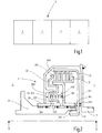
- Fig. 1 shows a schematic representation of a drive train 5 of a motor vehicle with an internal combustion engine 1, a dual mass flywheel 2, a clutch device 3 and a manual transmission 4.
- the internal combustion engine 1 is rotatably connected via a crankshaft or input shaft 11 with the dual mass flywheel 2 and the clutch device 3.
- the dual-mass flywheel 2 reduces torsional vibrations, which result from rotational irregularities of the internal combustion engine 1 and which propagate via the drive train 5 to the passenger compartment of the motor vehicle and are perceived by the driver as disturbing.
- the coupling device 3 is non-rotatably connected to the manual transmission 4 via an output shaft 41.
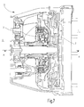
- Fig. 7 shows a part of the drive train 5 in view. With knowledge of the present invention, the skilled person can also use an electric motor or a hybrid drive instead of an internal combustion engine.
- the internal combustion engine 1, the dual-mass flywheel 2, the clutch device 3 and the manual transmission 4 are designed with different mass and different installation space.
- An internal combustion engine 1 with 750Nm torque is thus heavier in weight and larger in space than an internal combustion engine 1 with 150Nm torque, the same applies to the dual mass flywheel 2, the clutch device 3 and the manual transmission 4, also here are a dual mass flywheel 2, a clutch device 3 or a manual transmission 4 with 750 Nm of torque the mass forth heavier and greater in space than a dual mass flywheel 2, a clutch device 3 or a manual transmission 4 with 150Nm torque.
- a coupling device with a dry friction clutch weighs about 6 kg, while the clutch device 3 with a wet friction clutch weighs only about 4 kg, thus reducing the mass of the clutch device 3 is about 33%.
- the inertia on the input shaft 11 of the clutch device 3 with wet friction clutch around 10gm 2
- the inertia of the input shaft of a clutch device with dry friction about 75gm 2
- the reduction of the inertia of the input shaft 11 is about 85%.
- the mass inertia at the output shaft 41 of the clutch device 3 with wet friction clutch is approximately 2.6 gm 2
- the inertia at the output shaft of a clutch device with dry friction clutch is approximately 6.4 gm 2
- the reduction of the mass inertia at the output shaft 41 is approximately 60 %.
- the sum of the inertia of the input shaft and output shaft of a clutch device with dry friction approximately 82gm 2
- reducing the sum of the inertia of the input shaft 11 and output shaft 41 is around 85%.
- the space in the radial direction to the axis of rotation A of the coupling device 3 with wet friction clutch has a diameter of about 180mm, while the space in the radial direction to the axis of rotation of a coupling device with dry friction has a diameter of about 240mm, reducing the space in the radial direction to the axis of rotation is around 25%.
- the space in the axial direction to the axis of rotation A of the clutch device 3 with wet friction clutch is approximately 100mm, while the space in the axial direction to the axis of rotation of a clutch device with dry friction about 120mm, the reduction of Installation space in the axial direction to the axis of rotation is about 20%.
- the percentages are rounded to 5%.
- the Fig. 2 to 6 show parts of several embodiments of a coupling device 3. Unless otherwise stated, the characteristics of the drive train 5 are made of metal such as steel, for example S420MC, HC300LA, HC340LA.
- the input shaft 11 is rotatably connected via a spline DIN5480 with a drive plate 301 of the coupling device 3.
- the drive plate 301 extends substantially in the radial direction to the axis of rotation A.
- the drive plate 301 extends in the radial and axial direction to the axis of rotation A.
- the drive plate 301 is rotatably connected via a locking ring with a radially outer end of a basket 302.
- the basket 302 extends basket-shaped axially and radially with respect to the axis of rotation A. With a radially inner end of the basket 302 is rotatably connected to a rotary union 36. This connection can also be realized as a weld.
- the coupling device 3 has no basket 302 and the driver plate 301 is non-rotatably connected via a weld to a radially outer end of an input disk carrier 31.
- an output disk carrier 34 is disposed radially inside the driver disk 301 and the basket 302; and a piston 32 is disposed radially inside the basket 302.
- the output disk carrier 34 is disposed radially inside the driver disk 301; and the piston 32 is disposed radially inside the output disk carrier 34.
- the input disk carrier 31 is arranged radially inside the output disk carrier 34, according to the embodiment according to Fig. 3 the output disk carrier 34 is disposed radially within the input disk carrier 31.
- the rotary leadthrough 36 is substantially cylindrical and arranged coaxially with the input shaft 11 and the output shaft 41.
- the rotary feedthrough 36 via two radial bearings 361 such as needle bearings mounted directly above a housing fixed hub 35 rotatably.
- the rotary feedthrough 36 via two radial bearings 361 such as needle bearings mounted directly above the output shaft 41 rotatably.
- the hub 35 is formed substantially cylindrical and arranged coaxially with the input shaft 11 and the output shaft 41, it extends in the axial direction to the axis of rotation A between the dual-mass flywheel 2 and the manual transmission 4th
- a radially inner end of the input disk carrier 31 is rotatably connected to the rotary feedthrough 36.
- the input plate carrier 31 is T-shaped, according to the embodiment of FIG Fig. 3 and 6 the input disk carrier 31 is L-shaped.
- the input disk carrier 31 extends substantially in the radial direction to the axis of rotation A.
- the input disk carrier 31 carries a plurality of input fins 310.
- the output disk carrier 34 is rotatably supported via axial bearings 362 such as needle bearings with respect to the rotary feedthrough 36 and the drive plate 301.
- the output disk carrier 34 is rotatably supported via axial bearings 362 like needle bearings with respect to the rotary feedthrough 36.
- the output disk carrier 34 carries a plurality of output disks 340.
- the input disks 310 and the output disks 340 are annular and coaxial with the input shaft 11 and the output shaft 41.
- the lamellae are made of uncoated, thick steel lamellas and coated with friction lining, thin steel lamellae, also called friction lamellae.
- the friction discs have a positive to neutral friction characteristic.
- steel slats are shown as rectangles, while friction slats are shown as dashes.
- the lamellae are alternately arranged in a row in the axial direction to the rotation axis A.
- Four friction lamellae are arranged between five steel lamellae, these nine lamellae of input lamellae 310 and output lamellae 340 form a lamella packet.
- the input fins 310 and output fins 340 can be brought into frictional engagement.
- the piston 32 is in operative connection with the disk pack.
- the piston 32 extends substantially in the radial direction to the axis of rotation A.
- a radially inner end of the piston 32 loosely contacts the rotary leadthrough 36 and a radially outer end of the piston 32 can be pressed with a contact force against the disk set.
- Loose contact in the sense of the invention is understood as meaning a mechanical contact in which there is no frictional, positive-locking, cohesive or frictional connection, piston 32 and rotary leadthrough 36 are thus arranged to be movable relative to one another.
- the piston 32 is mounted axially displaceable to the axis of rotation A.
- the piston 32 is stored once or twice. According to the embodiment according to Fig.
- the piston 32 is displaceably mounted twice on the basket 302 and on the input disk carrier 31.
- the piston 32 is mounted twice on the basket 302 and on a support 37 slidably.
- An inner end of the carrier 37 is rotatably connected to the rotary feedthrough 36, the carrier 37 is L-shaped.
- the piston 32 is simply slidably mounted on the carrier 37.
- the piston 32 is displaceably mounted twice on the input disk carrier 31 and on the carrier 37.
- the piston 32 is mounted twice on two carriers 37, 37 'slidably.
- the coupling device 3 can be designed either as a normally open or normally closed wet friction clutch. In a normally open Nassreibkupplung the disk set is not normally in frictional engagement, since the piston 32 is spaced by means of a spring assembly 39 from the disk set and only by means of a Pumpenaktuatoran whatsoever 38 by the oil 33 against the disk pack can be pressed.
- the coupling device 3 according to the embodiments according to Fig. 2 . 3 . 4 and 5 is usually open. Conversely, in a normally closed Notwithstandingreibkupplung the piston 32 is pressed by means of the spring assembly 39 is normally against the disk set and spaced by means of Pumpenaktuatoran kann 38 from the disk set.
- the coupling device 3 according to the embodiment according to Fig. 6 is normally closed.
- the oil 33 is passed through an oil feed line 331 of the rotary feedthrough 36 into an oil chamber 332.
- the oil groove 335 communicates with an oil passage 383 of a pump actuator assembly 38 of the clutch device 3.
- the oil passage 331 communicates with an oil groove 335 in the hub 35 FIGS. 5 and 6 the oil supply line 331 communicates directly with the oil line 383 of the pump actuator assembly 38.
- the oil discharge back into an oil reservoir 384 is not shown figuratively.
- the pump actuator assembly 38 includes two electric motors 381, 381 'and two oil pumps 382, 382'.
- An electric motor 381 and an oil pump 382 is provided for the application of the disk set with oil 33.
- Another electric motor 381 'and a further oil pump 382' is provided for cooling the disk pack with oil 33.
- the oil pump 382 has two directions of rotation, the further oil pump 382 'has a direction of rotation. Due to the further electric motor 381 'and the further oil pump 382' only for the cooling of the disk set with oil 33, the cooling can be optimized and independent of the action of the disk set with oil 33 by the electric motor 381 and the oil pump 382 done.
- the skilled person can also provide only an electric motor 381 and an oil pump 382 for the application of oil to the plate pack 33.
- Each pair of electric motor 381, 381 'and oil pump 382, 382' is operatively connected to each other.
- a clutch control 385 of the clutch device 3 controls and controls the electric motor 381, 381 'with control and regulating signals which are transmitted from the clutch control 385 via an electrical control line 386 to the electric motor 381, 381'.
- the clutch controller 385 has a processor and a data memory. From the data store, an algorithm is loaded into the processor and executed. The executed algorithm controls and regulates the electric motor 381, 381 'with control and regulating signals.
- the electric motor 381, 381 ' When the electric motor 381, 381 'is activated, the electric motor 381, 381' drives the oil pump 382, 382 'in such a way that the oil pump 382, 382' sucks in oil 33 from an oil line 383, 383 'or oil 33 into the oil line 383, 383 'ejects.
- the oil line 383, 383 ' communicates with the oil supply line 331. The oil 33 is thus pumped back and forth between the oil reservoir 384 and the oil chamber 332.
- the clutch controller 385 is connected to a clutch pedal sensor 42 of a clutch pedal of the motor vehicle via an electric clutch pedal signal line 420, and the clutch controller 385 is connected via an electric accelerator pedal signal line 430 to an accelerator pedal sensor 43 of an accelerator pedal of the vehicle. Knowing the present invention, one skilled in the art may also provide only one electric clutch pedal signal line 420 between the clutch controller 385 and the clutch pedal sensor 42, or even only one electric accelerator signal line 430 between the clutch controller 385 and the accelerator pedal sensor 43. As soon as the driver operates the clutch pedal with a foot force, the clutch pedal sensor 42 outputs an electric clutch pedal signal 421, 422, which is transmitted to the clutch control 385 via the electric clutch pedal signal line 420. The foot force acting on the clutch pedal is in Fig.
- the clutch pedal sensor 420 detects elastic force-induced elastic deformation of a mechanical spring mounted on the clutch pedal.
- the mechanical spring is in Fig. 8 shown schematically.
- the clutch pedal sensor 420 outputs a positive electric clutch pedal signal 421.
- the clutch pedal sensor 420 outputs a negative electric clutch pedal signal 422 as soon as the driver reduces the pedal force applied to the clutch pedal below the predetermined threshold value, in this case, a non-acting foot force is used in the sense of the invention.
- the clutch pedal sensor 420 outputs only a positive electric clutch pedal signal 421 and only a negative electric clutch pedal signal 422, so it operates binary.
- the accelerator pedal sensor 43 outputs an electric Accelerator pedal signal 431, 432, which is transmitted via the second electrical signal line 430 to the clutch control 385 as soon as the driver operates the gas pedal with a foot force.
- the foot force acting on the gas pedal is in Fig. 8 shown schematically with an arrow.
- the accelerator pedal sensor 430 detects rotation of a shaft caused by foot force when the accelerator pedal is depressed.
- the accelerator pedal is attached to the shaft in a torque-proof manner.
- the wave is in Fig. 8 shown schematically.
- the gas pedal sensor 430 outputs a positive electric accelerator pedal signal 431.
- the accelerator pedal sensor 430 outputs a negative electric accelerator pedal signal 432 as soon as the driver reduces the foot force applied to the accelerator pedal below the predetermined threshold value, ie when no foot force acts on the accelerator pedal.
- the accelerator pedal sensor 430 outputs a plurality of accelerator signals 431, 432 for a plurality of different rotations of the shaft, for example, the accelerator pedal sensor 430 outputs thirty stepped accelerator pedal signals 431, 432 for thirty different rotated angular positions of the shaft.
- those skilled in the art may use other sensors for sensing the foot force applied to a clutch pedal or to an accelerator pedal.
- the clutch controller 385 For a positive electric clutch pedal signal 421 transmitted to the clutch controller 385, the clutch controller 385 generates a negative electrical actuator signal 388 which is communicated via the electrical control line 386 from the clutch controller 385 to the electric motor 381. For a negative electric clutch pedal signal 422 communicated to the clutch control 385, the clutch controller 385 generates a positive electrical actuator signal 387 which is communicated via the electrical control line 386 from the clutch control 385 to the electric motor 381. For a positive electric accelerator signal 431 communicated to the clutch control 385, the clutch controller 385 generates a positive electrical actuator signal 387 which is communicated via the electrical control line 386 from the clutch control 385 to the electric motor 381.
- the clutch controller 385 For a negative electrical accelerator pedal signal 432 communicated to the clutch control 385, the clutch controller 385 generates a negative electrical actuator signal 388 which is communicated via the electrical control line 386 from the clutch control 385 to the electric motor 381.
- a positive electric actuator signal 387 transmitted to the electric motor 381 drives the electric motor 381 to the oil pump 382 so that the input fins 310 and the output fins 340 are frictionally engaged.
- the electric motor 381 drives the oil pump 382 so that the input fins 310 and the output fins 340 are not frictionally engaged.
- the clutch device 3 For a drive train 5 with a predetermined torque of 350Nm, the clutch device 3 around 2-4Liter oil 33, the disk set is subjected to a maximum pressure of around 12bar in the oil chamber 332, the structure of the maximum pressure in the oil chamber 332 requires about 100-200msec and is much faster than the driver's required period of time to pedal-depress the clutch pedal or accelerator pedal so as to provide a clutch pedal signal 421, 422 through the clutch pedal sensor 420 or an accelerator pedal signal 431, 432 through the accelerator pedal sensor 430.
- These exemplary figures have a tolerance of plus / minus 10%.
- the dual mass flywheel 2 reduces torsional vibrations resulting from rotational nonuniformities of the internal combustion engine 1. Since the torsional vibrations in the drive train 5 occur resonance-like within a relatively large operating speed range, the dual-mass flywheel 2 usually has a plurality of spring stages and friction devices dimensioned for different torque ranges. A dual mass flywheel is thus relatively expensive and often prone to interference. Now the coupling device 3 is used for active vibration damping. For this purpose, the input fins 310 and the output fins 340 are operated in the slip.
- the input fins 310 and the output fins 340 are subjected to a predefined amount of oil 33, so that the input fins 310 and the output fins 340 slip toward one another.
- slip speeds are set via the predefined amount of oil 33 that the torsional vibrations are isolated.
- Typical slip speeds are 10 to 100 min -1 . Due to the positive to neutral friction characteristic of the friction plates can thus reduce torsional vibrations, as increases with increasing slip speed and the frictional engagement of the plate pack.
- Information about the predefined amounts of oil 33 are stored, for example, in a register in the data memory of the clutch control 385.
- clutch controller 385 is communicated via a non-figuratively shown electrical control line from a speed sensor also not shown figuratively, for example, transmits the speed sensor at regular intervals speed signals of the input shaft 41 to the clutch control 385th
- An algorithm of clutch control 385 then calculates from the speed signals the instantaneous torque range of the internal combustion engine 1.
- torsional vibrations are reduced both by the dual mass flywheel 2 and by the clutch device 3.
- the clutch device 3 with wet friction clutch compared to a coupling device with dry friction clutch has a reduced space in the axial direction to the axis of rotation A.
- the clutch device 3 with wet friction clutch has an approximately 85% reduced mass inertia on the input shaft 11 compared to a clutch device with a dry friction clutch; and / or that for a drive train 5 with a predetermined torque, the clutch device 3 with wet friction clutch in comparison to a coupling device with dry friction clutch reduced by about 60% inertia on the output shaft 41.
- the clutch device 3 with wet friction clutch compared to a clutch device with dry friction clutch reduced by about 85% sum of the inertia of the input shaft 11 and output shaft 41.
- the coupling device 3 with wet friction clutch in comparison to a coupling device with adjustreibkupplung has reduced by about 25% space in the radial direction to the axis of rotation A.
- the coupling device 3 with wet friction clutch has an installation space reduced by about 20% in the axial direction to the axis of rotation A compared to a coupling device with a dry friction clutch.
Landscapes
- Engineering & Computer Science (AREA)
- General Engineering & Computer Science (AREA)
- Mechanical Engineering (AREA)
- Physics & Mathematics (AREA)
- Fluid Mechanics (AREA)
- Chemical & Material Sciences (AREA)
- Combustion & Propulsion (AREA)
- Transportation (AREA)
- Hydraulic Clutches, Magnetic Clutches, Fluid Clutches, And Fluid Joints (AREA)
- Mechanical Operated Clutches (AREA)
- Arrangement Of Transmissions (AREA)
- Hybrid Electric Vehicles (AREA)
Abstract
Description
- Die vorliegende Erfindung betrifft eine Kupplungseinrichtung, die in einem Antriebsstrang zwischen einem Verbrennungsmotor und einem Handschaltgetriebe eines Kraftfahrzeuges angeordnet ist. Die Erfindung betrifft ferner ein Verfahren zum Betrieb der Kupplungseinrichtung, sowie einen Antriebsstrang eines Kraftfahrzeuges mit der Kupplungseinrichtung und zur Durchführung des Verfahrens zum Betrieb der Kupplungseinrichtung.
- Kraftfahrzeuge werden durch einen Verbrennungsmotor angetrieben, welcher über einen Antriebsstrang Kraft auf ein Fahrwerk überträgt. Im Sinne der vorliegenden Erfindung werden als Kraftfahrzeuge solche Kraftfahrzeuge verstanden, die nach der EG-Richtlinie 2007/46/EG vier Räder und eine zulässige Gesamtmasse von 12 Tonnen besitzen. Einer der wichtigsten Bestandteile des Antriebsstranges ist das Getriebe. Für den Einsatz in Kraftfahrzeugen sind heute verschiedene Getriebearten bekannt. Das für Kraftfahrzeuge in Europa, Indien und China am häufigsten gewählte Getriebe ist dabei das Handschaltgetriebe. Im Vergleich zu dem in den Vereinigten Staaten und Japan populären Automatikgetriebe ist das Handschaltgetriebe nicht nur robust und preisgünstig, sondern weist auch einen hohen Wirkungsgrad auf. Robustheit im Sinne der vorliegenden Erfindung bezeichnet eine Unempfindlichkeit gegenüber kurzzeitiger Überlastung, Fehlbedienung, usw.. Das Handschaltgetriebe ist preisgünstiger, da seine Herstellkosten lediglich 50% bis 66% derjenigen eines Automatikgetriebes betragen. Beim Handschaltgetriebe stehen dem Fahrer eines Kraftfahrzeuges heutzutage fünf, sechs und mehr Vorwärtsgänge zur Verfügung. Zusätzlich ist ein Rückwärtsgang verfügbar. Hierbei wählt der Fahrer, je nach Geschwindigkeit und Fahrrichtung des Kraftfahrzeuges, mit einem Schalthebel einen Gang aus.
- Um von einem Gang in den anderen zu wechseln, muss der Fahrer den Kraftschluss zwischen Verbrennungsmotor und Handschaltgetriebe unterbrechen. Aus diesem Grund ist der Verbrennungsmotor über eine Kupplungseinrichtung mit dem Handschaltgetriebe verbunden. Für Handschaltgetriebe sind Trockenreibkupplungen Stand der Technik. Dabei ist eine Druckplatte drehfest mit dem Verbrennungsmotor und eine Mitnehmerscheibe drehfest mit dem Handschaltgetriebe verbunden sind. Durch Betätigen eines Kupplungspedals stellt der Fahrer selber einen Reibschluss zwischen den Reibelementen Druckplatte und Mitnehmerscheibe her. Eine solche Trockenreibkupplung ist aus der Schrift
DE10222730A1 bekannt. - Bei Kraftfahrzeugen mit einem Automatikgetriebe hingegen wird häufig eine Nassreibkupplung verwendet, bei der Lamellen als Reibelemente mit einem Öl beaufschlagt werden. Eine derartige Nassreibkupplung ist aus der Schrift
DE102004030660A1 bekannt. - Im direkten Vergleich zwischen Trockenreibkupplung und Nassreibkupplung zeichnet sich die Trockenreibkupplung durch Robustheit, einen günstigen Preis und einen hohen Wirkungsgrad aus. Die Nassreibkupplung verfügt hingegen über eine bessere Kühlung der Reibelemente. Bei der Trockenreibkupplung werden die Reibelemente durch Luft und bei der Nassreibkupplung durch Öl gekühlt. Da Luft eine niedrigere Wärmekapazität als Öl besitzt, besteht bei der Trockenreibkupplung die Gefahr, dass bei wiederholter, dauerhafter Überlastung wie beim Stop-and-Go-Betrieb im Verkehrsstau die Reibbeläge aufgrund der hohen thermischen Energieeinträge verschleißen.
- Es ist daher eine erste Aufgabe der vorliegenden Erfindung, einen durch hohe thermische Energieeinträge verursachten Verschleiß der Kupplungseinrichtung eines Kraftfahrzeuges mit Handschaltgetriebe zu vermeiden.
- Im Sinne der vorliegenden Erfindung bezeichnet die Fahrdynamik eines Kraftfahrzeuges das Verhalten der beschleunigten und unbeschleunigten Massen im Kraftfahrzeug, die zu vom Fahrer als störend empfundenen Schwingungen führen können. Diese Schwingungen beeinflussen das Fahrverhalten des Kraftfahrzeuges wie die Spurtreue und die Beschleunigung. Die Schwingungen beeinflussen aber auch den Fahrkomfort im Kraftfahrzeug, da sich die Schwingungen als Körperschall zur Fahrgastzelle des Kraftfahrzeuges ausbreiten. Schließlich hat auch die Art und Weise der Kupplungsbetätigung durch den Fahrer Einfluss auf die Fahrdynamik. So kann der Fahrer die Reibelemente unnötig lange und häufig im Reibschluss halten, oder er kann den Reibschluss zu schnell bei zu großen Drehzahldifferenzen der Reibelemente herstellen. Eine derart suboptimale Kupplungsbetätigung durch den Fahrer erhöht sowohl den Kraftstoffverbrauch als auch den CO2-Ausstoß und reduziert die Reichweite des Kraftfahrzeuges.
- Eine weitere Aufgabe der vorliegenden Erfindung besteht darin, die Fahrdynamik eines Kraftfahrzeuges mit Handschaltgetriebe zu verbessern.
- Unter dem benötigten Bauraum eines Antriebsstranges im Sinne der vorliegenden Erfindung wird das Volumen verstanden, dass für den Antriebsstrang benötigt wird, um die Kraft des Verbrennungsmotors auf das Fahrwerk zu übertragen und dabei die Nebenbedingungen wie Betriebssicherheit, Robustheit, Kostengünstigkeit, Fahrdynamik, Wirkungsgrad zu erfüllen. Gerade bei Kraftfahrzeugen mit Front-Quer-Antrieb ist der für den Antriebsstrang verfügbare Bauraum oft sehr knapp bemessen.
- Zudem stellt sich die vorliegende Erfindung die Aufgabe, den für einen Antriebstrang benötigten Bauraum eines Kraftfahrzeuges mit Handschaltgetriebe zu reduzieren.
- Und die vorliegende Erfindung stellt sich die zusätzliche Aufgabe, die Betriebssicherheit des Kraftfahrzeuges mit Handschaltgetriebe weiter zu verbessern.
- Zumindest eine dieser Aufgaben wird erfindungsgemäß durch die Kupplungseinrichtung des unabhängigen Anspruchs 1 gelöst. Die Kupplungseinrichtung ist in einem Antriebsstrang zwischen einem Verbrennungsmotor und einem Handschaltgetriebe eines Kraftfahrzeuges angeordnet; eine Eingangswelle ist drehfest mit dem Verbrennungsmotor verbunden und eine Ausgangswelle ist drehfest mit dem Handschaltgetriebe verbunden; die Eingangswelle ist drehfest mit einem Eingangslamellenträger verbunden und die Ausgangswelle ist drehfest mit einem Ausgangslamellenträger verbunden; der Eingangslamellenträger trägt Eingangslamellen und der Ausgangslamellenträger trägt Ausgangslamellen; und die Eingangslamellen und die Ausgangslamellen sind mit Öl beaufschlagbar und kühlbar.
- Durch diese Kupplungseinrichtung wird der Kraftschluss zwischen Verbrennungsmotor und Handschaltgetriebe mittels einer Nassreibkupplung unterbrochen. Da die Ölkühlung der Reibelemente der Nassreibkupplung im Vergleich zur Luftkühlung der Reibelemente bei der Trockenreibkupplung effizienter ist, können die Reibelemente der Nassreibkupplung mit einer im Vergleich zur Trockenreibkupplung geringeren Masse ausgelegt werden, was Gewicht spart. Es hat sich herausgestellt, dass für einen Antriebsstrang mit vorgegebenem Drehmoment, die Kupplungseinrichtung mit Nassreibkupplung im Vergleich zu einer Kupplungseinrichtung mit Trockenreibkupplung eine um rund 33% reduzierte Masse aufweist, was wiederum die Massenträgheit an der Eingangswelle und an der Ausgangswelle deutlich reduziert und die Fahrdynamik des Kraftfahrzeuges verbessert.
- Diese Aufgabe wird somit vollkommen gelöst. Vorteilhafte Ausführungen und Weiterbildungen der Erfindung sind in den abhängigen Ansprüchen angegeben.
- Vorzugsweise ist die Eingangswelle drehfest mit einer Mitnehmerscheibe verbunden; und der Ausgangslamellenträger ist radial innerhalb der Mitnehmerscheibe angeordnet.
- Die Mitnehmerscheibe ist auf der Seite der Kupplungseinrichtung in Richtung eines Zweimassenschwungrades angeordnet. Diese verschachtelte Anordnung von Mitnehmerscheibe und Ausgangslamellenträger ist platzsparend.
- Vorzugsweise ist ein radial inneres Ende des Eingangslamellenträgers drehfest mit einer Drehdurchführung verbunden; und die Drehdurchführung ist direkt oberhalb einer gehäusefesten Nabe drehbar gelagert oder die Drehdurchführung ist direkt oberhalb der Ausgangswelle drehbar gelagert.
- Durch diese sich mit dem Innenlamellenträger im Betrieb der Kupplungseinrichtung drehende Drehdurchführung wird das Öl zur Beaufschlagung der Eingangslamellen und der Ausgangslamellen in die Kupplungseinrichtung geleitet. Die Drehdurchführung ist entweder direkt oberhalb der gehäusefesten Nabe drehbar gelagert oder sie ist direkt oberhalb der Ausgangswelle gelagert. Durch die minimale Masse der Drehdurchführung wird die Masse der Kupplungseinrichtung reduziert.
- Vorzugsweise ist ein radial inneres Ende des Eingangslamellenträgers drehfest mit einer Drehdurchführung verbunden; und der Eingangslamellenträger ist radial innerhalb des Ausgangslamellenträgers angeordnet.
- Durch die sich im Betrieb der Kupplungseinrichtung mit dem Innenlamellenträger drehende Drehdurchführung wird Öl zur Kühlung der Eingangslamellen und der Ausgangslamellen in die Kupplungseinrichtung geleitet. Das Öl wird dann durch die Fliehkraft und mittels Öffnungen im Eingangslamellenträger und im Ausgangslamellenträger sowie mittels Nuten in den Eingangslamellen und Ausgangslamellen von radial innen nach radial außen auf die Eingangslamellen und Ausgangslamellen verteilt. Bei stehendem Kraftfahrzeug am Berg und laufendem Verbrennungsmotor dreht sich nur der Eingangslamellenträger mit der Eingangswelle, während sich der Ausgangslamellenträger nicht dreht. Solch eine Betriebssituation entsteht im Berganfahr-Betrieb. Bei einem Ausgangslamellenträger, der radial innerhalb des Eingangslamellenträgers angeordnet ist und sich nicht dreht, blockiert dieser Ausgangslamellenträger die durch die Fliehkraft erzeugte Verteilung des Öls, wodurch die Eingangslamellen Gefahr laufen, aufgrund ungenügender Kühlung zu verschleißen. Durch die Anordnung des Eingangslamellenträgers radial innerhalb des Ausgangslamellenträgers wird ein durch hohe thermische Energieeinträge verursachter Verschleiß der Kupplungseinrichtung vermieden.
- Vorzugsweise ist die Eingangswelle drehfest mit einer Mitnehmerscheibe verbunden; die Mitnehmerscheibe ist drehfest mit einem Korb verbunden; und der Ausgangslamellenträger ist radial innerhalb der Mitnehmerscheibe und des Korbs angeordnet.
- Der Korb ist auf der Seite der Kupplungseinrichtung in Richtung des Handschaltgetriebes angeordnet. Auch durch diese verschachtelte Anordnung des Ausgangslamellenträgers radial innerhalb von Mitnehmerscheibe und Korb ist platzsparend.
- In einem Verfahren zum Betrieb der Kupplungseinrichtung wird der Reibschluss der Eingangslamellen und der Ausgangslamellen mittels einer Federanordnung aufgehoben und mittels einer Pumpenaktuatoranordnung hergestellt; oder der Reibschluss der Eingangslamellen und der Ausgangslamellen wird mittels einer Federanordnung hergestellt und mittels einer Pumpenaktuatoranordnung aufgehoben.
- In diesem Verfahren wird die Nassreibkupplung der Kupplungseinrichtung mittels einer Federanordnung und einer Pumpenaktuatoranordnung in offene und geschlossene Positionen bewegt. Die Kupplungseinrichtung kann sowohl als normalerweise offene oder auch als normalerweise geschlossene Nassreibkupplung betrieben werden. Bei einer normalerweise offenen Nassreibkupplung ist der Reibschluss der Eingangslamellen und der Ausgangslamellen durch die Federanordnung aufgehoben und wird durch die eingeschaltete Pumpenaktuatoranordnung erzeugt. Der Fahrer kann im Notfall, bei ausgefallener Pumpenaktuatoranordnung, mit dem Kraftfahrzeug noch in eine sichere Parkposition weiterrollen, da kein Kraftschluss zwischen Verbrennungsmotor und Handschaltgetriebe unterbrochen ist. Bei einer normalerweise geschlossenen Nassreibkupplung wird der Reibschluss der Eingangslamellen und der Ausgangslamellen durch die Federanordnung erzeugt und erst durch die eingeschaltete Pumpenaktuatoranordnung aufgehoben, sie arbeitet aktiv gegen die Federanordnung. Wenn also der Fahrer das Kraftfahrzeug in einer Parkposition geparkt hat und die Pumpenaktuatoranordnung ausgeschaltet ist, so ist das geparkte Kraftfahrzeug durch den Kraftschluss zwischen Verbrennungsmotor und Handschaltgetriebe und bei eingelegter Gangstufe selbsttätig gegen Wegrollen in der Ebene blockiert und der Fahrer muss zur Sicherheit gegen Wegrollen in der Ebene keine Handbremse mehr ziehen und im Kraftfahrzeug ist auch keine Parksperre vorzusehen. Durch diese Maßnahmen wird die Betriebssicherheit des Kraftfahrzeuges auf unterschiedliche Art und Weise verbessert.
- Vorzugsweise wird die Kupplungseinrichtung mit einem Kupplungspedalsensor betrieben; falls vom Kupplungspedalsensor eine auf ein Kupplungspedal wirkende Fußkraft erfasst wird, wird vom Kupplungspedalsensor ein positives elektrisches Kupplungspedalsignal ausgegeben; das positive elektrische Kupplungspedalsignal wird an eine Kupplungssteuerung übermittelt; von der Kupplungssteuerung wird für ein positives elektrisches Kupplungspedalsignal ein negatives elektrisches Aktuatorsignal erzeugt; das negative elektrische Aktuatorsignal wird an einen Elektromotor übermittelt; und vom Elektromotor wird für ein übermitteltes negatives elektrisches Aktuatorsignal eine Ölpumpe so angetrieben, dass die Eingangslamellen und die Ausgangslamellen nicht im Reibschluss sind.
- Durch diese Kupplungseinrichtung wird der Elektromotor mit einem negativen elektrischen Aktuatorsignal angesteuert. Die Kupplungssteuerung erzeugt dieses negative elektrische Aktuatorsignal, falls der Kupplungspedalsensor eine Fußkraft erfasst und ein positives elektrisches Kupplungspedalsignal ausgibt. Es ist somit die Kupplungssteuerung, die für ein positives elektrisches Kupplungspedalsignal den Reibschluss zwischen den Eingangslamellen und den Ausgangslamellen aufhebt, sie kuppelt selbsttätig aus. Für den Fahrer wird die Kupplungsbetätigung somit deutlich vereinfacht, da die Kupplungssteuerung den Reibschluss rascher und wirksamer als der Fahrer aufhebt und die Fahrdynamik des Kraftfahrzeuges verbessert.
- Vorzugsweise wird die Kupplungseinrichtung mit einem Kupplungspedalsensor betrieben; falls vom Kupplungspedalsensor keine auf ein Kupplungspedal wirkende Fußkraft erfasst wird, wird vom Kupplungspedalsensor ein negatives elektrisches Kupplungspedalsignal ausgegeben; das negative elektrische Kupplungspedalsignal wird an eine Kupplungssteuerung übermittelt; von der Kupplungssteuerung wird für ein negatives elektrisches Kupplungspedalsignal ein positives elektrisches Aktuatorsignal erzeugt; das positive elektrische Aktuatorsignal wird an einen Elektromotor übermittelt; und vom Elektromotor wird für ein übermitteltes positives elektrisches Aktuatorsignal eine Ölpumpe so angetrieben, dass die Eingangslamellen und die Ausgangslamellen im Reibschluss sind.
- Durch diese Kupplungseinrichtung wird ein Elektromotor mit einem positiven elektrischen Aktuatorsignal angesteuert. Umgekehrt zum negativen elektrischen Aktuatorsignal, erzeugt die Kupplungssteuerung dieses positive elektrische Aktuatorsignal für ein vom Kupplungspedalsensor erhaltenes negatives elektrisches Kupplungspedalsignal. Für den Fahrer wird die Kupplungsbetätigung somit deutlich vereinfacht, da er durch Betätigen des Kupplungspedals nicht mehr selber den Reibschluss zwischen den Eingangslamellen und den Ausgangslamellen herstellt, sondern lediglich eine Fußkraft bereitstellt, die vom Kupplungspedalsensor erfasst wird. Es ist somit die Kupplungssteuerung, die für ein positives elektrisches Kupplungspedalsignal den Reibschluss zwischen den Eingangslamellen und den Ausgangslamellen herstellt, sie kuppelt selbsttätig ein. Da die Kupplungssteuerung den Reibschluss rascher und wirksamer als der Fahrer herstellt, wird die Fahrdynamik des Kraftfahrzeuges verbessert.
- Vorzugsweise wird die Kupplungseinrichtung mit einem Gaspedalsensor betrieben; falls vom Gaspedalsensor eine auf ein Gaspedal wirkende Fußkraft erfasst wird, wird vom Gaspedalsensor ein positives elektrisches Gaspedalsignal ausgegeben; das positive elektrische Gaspedalsignal wird an eine Kupplungssteuerung übermittelt; von der Kupplungssteuerung wird für ein positives elektrisches Gaspedalsignal ein positives elektrisches Aktuatorsignal erzeugt; das positive elektrische Aktuatorsignal wird an einen Elektromotor übermittelt; und vom Elektromotor wird für ein übermitteltes positives elektrisches Aktuatorsignal eine Ölpumpe so angetrieben, dass die Eingangslamellen und die Ausgangslamellen im Reibschluss sind.
- Durch diese Kupplungseinrichtung wird der Elektromotor mit einem positiven elektrischen Aktuatorsignal angesteuert. Das positive elektrische Aktuatorsignal wird von der Kupplungssteuerung für ein von einem Gaspedalsensor erhaltenes positives elektrisches Gaspedalsignal erzeugt. Es ist somit die Kupplungssteuerung, die für ein positives elektrisches Gaspedalsignal den Reibschluss zwischen den Eingangslamellen und den Ausgangslamellen herstellt, sie kuppelt selbsttätig ein. Der Fahrer muss somit lediglich das Gaspedal betätigen und eine Fußkraft bereitstellen, die vom Kupplungspedalsensor erfasst wird, und die Kupplungssteuerung stellt den Reibschluss zwischen den Eingangslamellen und den Ausgangslamellen her, sie kuppelt selbsttätig ein. Da die Kupplungssteuerung den Reibschluss rascher und wirksamer als der Fahrer herstellt, wird die Fahrdynamik des Kraftfahrzeuges verbessert.
- Vorzugsweise wird, falls eine niedrige Gangstufe des Handschaltgetriebes eingelegt ist, für ein positives elektrisches Aktuatorsignal eine Ölpumpe so angetrieben, dass die Eingangslamellen und die Ausgangslamellen im Reibschluss sind und ein Kraftschluss zwischen Verbrennungsmotor und Handschaltgetriebe gebildet wird und das Kraftfahrzeug anfährt.
- Somit wird falls eine niedrige Gangstufe des Handschaltgetriebes eingelegt ist und das Gaspedal niedergedrückt wird, das Kraftfahrzeug selbsttätig angefahren. Es ist die Kupplungssteuerung, die für ein positives elektrisches Gaspedalsignal den Reibschluss zwischen den Eingangslamellen und den Ausgangslamellen selbsttätig herstellt und so den Kraftschluss zwischen Verbrennungsmotor und Handschaltgetriebe bildet und das Kraftfahrzeug selbsttätig anfährt. Unter einer niedrigen Gangstufe wird im Sinne der Erfindung eine solche niedrige Gangstufe des Kraftfahrzeuges verstanden, in der das Kraftfahrzeug aus dem Stand anfahren kann, normalerweise sind das die niedrigste und die zweitniedrigste Gangstufe. Dies ist gerade im Stop-and-Go-Betrieb im Verkehrsstau von Vorteil, da der Fahrer nun nicht mehr das Kupplungspedal betätigen muss, was sowohl den Kraftstoffverbrauch als auch den CO2-Ausstoß reduziert und die Reichweite des Kraftfahrzeuges erhöht, was wiederum die Fahrdynamik des Kraftfahrzeuges verbessert.
- Vorzugsweise wird die Kupplungseinrichtung mit einem Gaspedalsensor betrieben; falls vom Gaspedalsensor keine auf ein Gaspedal wirkende Fußkraft erfasst wird, wird vom Gaspedalsensor ein negatives elektrisches Gaspedalsignal ausgegeben; das negative elektrische Gaspedalsignal wird an eine Kupplungssteuerung übermittelt; von der Kupplungssteuerung wird für ein negatives elektrisches Gaspedalsignal ein negatives elektrisches Aktuatorsignal erzeugt; das negative elektrische Aktuatorsignal wird an einen Elektromotor übermittelt; und vom Elektromotor wird für ein übermitteltes negatives elektrisches Aktuatorsignal eine Ölpumpe so angetrieben, dass die Eingangslamellen und die Ausgangslamellen nicht im Reibschluss sind.
- Durch diese Kupplungseinrichtung wird der Elektromotor mit einem negativen elektrischen Aktuatorsignal angesteuert. Das negative elektrische Aktuatorsignal wird von der Kupplungssteuerung für ein von einem Gaspedalsensor erhaltenes negatives elektrisches Gaspedalsignal erzeugt. Es ist somit die Kupplungssteuerung, die für ein negatives elektrisches Gaspedalsignal den Reibschluss zwischen den Eingangslamellen und den Ausgangslamellen aufhebt.
- Vorzugsweise wird, falls eine Gangstufe des Handschaltgetriebes eingelegt ist, für ein negatives elektrisches Aktuatorsignal die Ölpumpe so angetrieben, dass die Eingangslamellen und die Ausgangslamellen nicht im Reibschluss sind und ein Kraftschluss zwischen Verbrennungsmotor und Handschaltgetriebe unterbrochen wird und das Kraftfahrzeug segelt.
- Somit segelt, falls eine Gangstufe des Handschaltgetriebes gelegt ist und das Gaspedal nicht betätigt wird, das Kraftfahrzeug im Leerlauf. Es ist die Kupplungssteuerung, die für ein negatives elektrisches Gaspedalsignal den Reibschluss zwischen den Eingangslamellen und den Ausgangslamellen selbsttätig aufhebt und so den Kraftschluss zwischen Verbrennungsmotor und Handschaltgetriebe unterbricht und das Kraftfahrzeug im Leerlauf segelt. Beim Segelbetrieb ist der Verbrennungsmotor vom Antriebsstrang abgekoppelt, somit dreht nur die Eingangswelle, was den Wirkungsgrad des Kraftfahrzeuges erhöht, eine Maßnahme durch welche der Kraftstoffverbrauch und der CO2-Ausstoß reduziert und die Reichweite des Kraftfahrzeuges erhöht werden, durch all dies wird die Fahrdynamik des Kraftfahrzeuges verbessert.
- Vorzugsweise werden die Eingangslamellen und die Ausgangslamellen mit einer vordefinierten Menge Öl beaufschlagt; über die Beaufschlagung der Eingangslamellen und der Ausgangslamellen mit einer vordefinierten Menge Öl werden Schlupfdrehzahlen für einen Schlupf zwischen den Eingangslamellen und den Ausgangslamellen eingestellt; und mittels der schlupfenden Eingangslamellen und Ausgangslamellen werden Drehschwingungen isoliert.
- Durch diesen schlupfenden Betrieb der Kupplungseinrichtung werden Drehschwingungen, die von Drehungleichförmigkeiten des Verbrennungsmotors herrühren und die sich über den Antriebsstrang zur Fahrgastzelle des Kraftfahrzeuges ausbreiten und dort vom Fahrer als störend empfunden werden, aktiv isolieren, was die Fahrdynamik des Kraftfahrzeuges verbessert. Diese aktive Isolierung der Drehschwingungen erfolgt durch die Kupplungssteuerung, die die Eingangslamellen und die Ausgangslamellen mit einer vordefinierten Menge Öl beaufschlagt. Bei Kraftfahrzeugen mit Handschaltgetriebe und Trockenreibkupplung ist ein solcher schlupfender Betrieb der Trockenreibkupplung nicht möglich, da eine entsprechende Kupplungssteuerung nicht vorhanden ist.
- Die vorstehend genannten und die nachstehend noch zu erläuternden Merkmale sind nicht nur in der jeweils angegebenen Kombination, sondern auch in anderen Kombinationen oder in Alleinstellung verwendbar, ohne den Rahmen der vorliegenden Erfindung zu verlassen.
- Die Erfindung wird in den Figuren beispielhaft dargestellt und in der Beschreibung der Figuren näher erläutert. Es zeigen:
- Fig. 1
- eine schematische Darstellung eines Antriebsstanges eines Kraftfahrzeuges mit einer Ausführungsform einer Kupplungseinrichtung nach einer der
Fig. 2 bis 6 ; - Fig. 2
- einen Teil einer ersten Ausführungsform einer Kupplungseinrichtung;
- Fig. 3
- einen Teil einer zweiten Ausführungsform einer Kupplungseinrichtung;
- Fig. 4
- einen Teil einer dritten Ausführungsform einer Kupplungseinrichtung;
- Fig. 5
- einen Teil einer vierten Ausführungsform einer Kupplungseinrichtung;
- Fig. 6
- einen Teil einer fünften Ausführungsform einer Kupplungseinrichtung;
- Fig. 7
- eine Ansicht eines Teils des Antriebsstanges eines Kraftfahrzeuges mit einer Ausführungsform der Kupplungseinrichtung nach einer der
Fig. 2 bis 6 ; und - Fig. 8
- eine schematische Darstellung einer Pumpenaktuatoranordnung einer Kupplungseinrichtung nach einer der
Fig. 2 bis 6 . - In der nachfolgenden Beschreibung der
Figuren 1 bis 8 werden ähnliche Merkmale mit den gleichen Bezugszeichen versehen. Sollten gravierende Unterschiede zwischen einzelnen Merkmalen vorhanden sein, wird explizit hingewiesen werden. -
Fig. 1 zeigt eine schematische Darstellung eines Antriebsstanges 5 eines Kraftfahrzeuges mit einem Verbrennungsmotor 1, einem Zweimassenschwungrad 2, einer Kupplungseinrichtung 3 und einem Handschaltgetriebe 4. Der Verbrennungsmotor 1 ist über eine Kurbelwelle oder Eingangswelle 11 drehfest mit dem Zweimassenschwungrad 2 und der Kupplungseinrichtung 3 verbunden. Das Zweimassenschwungrad 2 reduziert Drehschwingungen, die von Drehungleichförmigkeiten des Verbrennungsmotors 1 herrühren und die sich über den Antriebsstrang 5 zur Fahrgastzelle des Kraftfahrzeuges ausbreiten und dort vom Fahrer als störend empfunden werden. Die Kupplungseinrichtung 3 ist über eine Ausgangswelle 41 drehfest mit dem Handschaltgetriebe 4 verbunden.Fig. 7 zeigt einen Teil des Antriebsstrangs 5 in Ansicht. Bei Kenntnis der vorliegenden Erfindung kann der Fachmann anstatt eines Verbrennungsmotors auch einen Elektromotor oder einen Hybridantrieb verwenden. - Je nach vorgegebenem Drehmoment des Antriebsstranges 5, sind der Verbrennungsmotor 1, das Zweimassenschwungrad 2, die Kupplungseinrichtung 3 und das Handschaltgetriebe 4 mit unterschiedlicher Masse und unterschiedlichem Bauraum ausgelegt. Ein Verbrennungsmotor 1 mit 750Nm Drehmoment ist somit von der Masse her schwerer und vom Bauraum her größer als ein Verbrennungsmotor 1 mit 150Nm Drehmoment, das gleiche gilt auch für das Zweimassenschwungrad 2, die Kupplungseinrichtung 3 und das Handschaltgetriebe 4, auch hier sind ein Zweimassenschwungrad 2, eine Kupplungseinrichtung 3 oder ein Handschaltgetriebe 4 mit 750Nm Drehmoment von der Masse her schwerer und vom Bauraum her größer als ein Zweimassenschwungrad 2, eine Kupplungseinrichtung 3 oder ein Handschaltgetriebe 4 mit 150Nm Drehmoment. Wenn man nun für ein vorgegebenes Drehmoment eine Kupplungseinrichtung mit Trockenreibkupplung mit einer Kupplungseinrichtung mit Nassreibkupplung vergleicht, so ist die Kupplungseinrichtung mit Trockenreibkupplung von der Masse her schwerer und vom Bauraum her größer als eine Kupplungseinrichtung mit Nassreibkupplung.
- Für einen Antriebsstrang 5 mit vorgegebenem Drehmoment von 350Nm wiegt eine Kupplungseinrichtung mit Trockenreibkupplung rund 6kg, während die Kupplungseinrichtung 3 mit Nassreibkupplung nur rund 4kg wiegt, die Reduzierung der Masse der Kupplungseinrichtung 3 beträgt also rund 33%. Für diesen Antriebsstrang 5 beträgt die Massenträgheit an der Eingangswelle 11 der Kupplungseinrichtung 3 mit Nassreibkupplung rund 10gm2, während die Massenträgheit an der Eingangswelle einer Kupplungseinrichtung mit Trockenreibkupplung rund 75gm2 beträgt, die Reduzierung der Massenträgheit an der Eingangswelle 11 beträgt rund 85%. Für diesen Antriebsstrang 5 beträgt die Massenträgheit an der Ausgangswelle 41 der Kupplungseinrichtung 3 mit Nassreibkupplung rund 2,6gm2, während die Massenträgheit an der Ausgangswelle einer Kupplungseinrichtung mit Trockenreibkupplung rund 6,4gm2 beträgt, die Reduzierung der Massenträgheit an der Ausgangswelle 41 beträgt rund 60%. Für diesen Antriebsstrang 5 beträgt die Summe der Massenträgheit von Eingangswelle 11 und Ausgangswelle 41 der Kupplungseinrichtung 3 mit Nassreibkupplung rund 13gm2, während die Summe der Massenträgheit von Eingangswelle und Ausgangswelle einer Kupplungseinrichtung mit Trockenreibkupplung rund 82gm2 beträgt, die Reduzierung der Summe der Massenträgheit von Eingangswelle 11 und Ausgangswelle 41 beträgt rund 85%. Für diesen Antriebsstrang 5 weist der Bauraum in radialer Richtung zur Drehachse A der Kupplungseinrichtung 3 mit Nassreibkupplung einen Durchmesser von rund 180mm, während der Bauraum in radialer Richtung zur Drehachse einer Kupplungseinrichtung mit Trockenreibkupplung einen Durchmesser von rund 240mm aufweist, die Reduzierung des Bauraumes in radialer Richtung zur Drehachse beträgt rund 25%. Für diesen Antriebsstrang 5 beträgt der Bauraum in axialer Richtung zur Drehachse A der Kupplungseinrichtung 3 mit Nassreibkupplung rund 100mm, während der Bauraum in axialer Richtung zur Drehachse einer Kupplungseinrichtung mit Trockenreibkupplung rund 120mm beträgt, die Reduzierung des Bauraumes in axialer Richtung zur Drehachse beträgt rund 20%. Im Sinne der vorliegenden Erfindung sind die Prozentangaben auf 5% gerundet.
- Die
Fig. 2 bis 6 zeigen Teile von mehreren Ausführungsformen einer Kupplungseinrichtung 3. Wenn nicht anders erwähnt, sind die Merkmale des Antriebsstranges 5 aus Metall wie Stahl, beispielsweise S420MC, HC300LA, HC340LA. Die Eingangswelle 11 ist über eine Steckverzahnung nach DIN5480 drehfest mit einer Mitnehmerscheibe 301 der Kupplungseinrichtung 3 verbunden. Gemäß der Ausführungsformen nachFig. 2 und3 erstreckt sich die Mitnehmerscheibe 301 im Wesentlichen in radialer Richtung zur Drehachse A. Gemäß der Ausführungsformen nachFig. 4 und5 erstreckt sich die Mitnehmerscheibe 301 in radialer und axialer Richtung zur Drehachse A. Gemäß der Ausführungsformen nachFig. 2 und3 ist die Mitnehmerscheibe 301 über einen Sicherrungsring drehfest mit einem radial äußeren Ende eines Korbes 302 verbunden. Der Korb 302 erstreckt sich korbförmig axial und radial bezüglich der Drehachse A. Mit einem radial inneren Ende ist der Korb 302 drehfest mit einer Drehdurchführung 36 verbunden. Auch diese Verbindung kann als Schweißnaht realisiert sein. Gemäß der Ausführungsformen nachFig. 4 ,5 und 6 weist die Kupplungseinrichtung 3 keinen Korb 302 auf und die Mitnehmerscheibe 301 ist über eine Schweißnaht drehfest mit einem radial äußeren Ende eines Eingangslamellenträgers 31 verbunden. - Gemäß der Ausführungsformen nach
Fig. 2 und3 ist ein Ausgangslamellenträger 34 radial innerhalb der Mitnehmerscheibe 301 und des Korbs 302 angeordnet; und ein Kolben 32 ist radial innerhalb des Korbs 302 angeordnet. Gemäß der Ausführungsformen nachFig. 4 ,5 und 6 ist der Ausgangslamellenträger 34 radial innerhalb der Mitnehmerscheibe 301 angeordnet; und der Kolben 32 ist radial innerhalb des Ausgangslamellenträgers 34 angeordnet. - Gemäß der Ausführungsformen nach
Fig. 2 ,4 ,5 und 6 ist der Eingangslamellenträger 31 radial innerhalb des Ausgangslamellenträgers 34 angeordnet, gemäß der Ausführungsform nachFig. 3 ist der Ausgangslamellenträger 34 radial innerhalb des Eingangslamellenträgers 31 angeordnet. - Die Drehdurchführung 36 ist im Wesentlichen zylindrisch ausgebildet und koaxial zur Eingangswelle 11 und zur Ausgangswelle 41 angeordnet. Gemäß der Ausführungsformen nach
Fig. 2 ,3 und 4 ist die Drehdurchführung 36 über zwei radiale Lager 361 wie Nadellager direkt oberhalb einer gehäusefesten Nabe 35 drehbar gelagert. Gemäß der Ausführungsformen nachFig. 5 und 6 ist die Drehdurchführung 36 über zwei radiale Lager 361 wie Nadellager direkt oberhalb der Ausgangswelle 41 drehbar gelagert. Auch die Nabe 35 ist im Wesentlichen zylindrisch ausgebildet und koaxial zur Eingangswelle 11 und zur Ausgangswelle 41 angeordnet, sie erstreckt sich in axialer Richtung zur Drehachse A zwischen dem Zweimassenschwungrad 2 und dem Handschaltgetriebe 4. - Ein radial inneres Ende des Eingangslamellenträgers 31 ist drehfest mit der Drehdurchführung 36 verbunden. Gemäß der Ausführungsformen nach
Fig. 2 ,4 und5 ist der Eingangslamellenträger 31 T-förmig, gemäß der Ausführungsform nachFig. 3 und6 ist der Eingangslamellenträger 31 L-förmig. Der Eingangslamellenträger 31 erstreckt sich im Wesentlichen in radialer Richtung zur Drehachse A. Der Eingangslamellenträger 31 trägt mehrere Eingangslamellen 310. Somit ist die Eingangswelle 11 über Mitnehmerscheibe 301, Korb 302 und Drehdurchführung 36 drehfest mit dem Eingangslamellenträger 31 verbunden. Die Ausgangswelle 41 ist drehfest mit einem Ausgangslamellenträger 34 verbunden. Gemäß der Ausführungsformen nachFig. 2 ,3 und 4 ist der Ausgangslamellenträger 34 über axiale Lager 362 wie Nadellager bezüglich der Drehdurchführung 36 und der Mitnehmerscheibe 301 drehbar gelagert. Gemäß der Ausführungsformen nachFig. 5 und 6 ist der Ausgangslamellenträger 34 über axiale Lager 362 wie Nadellager bezüglich der Drehdurchführung 36 drehbar gelagert. Der Ausgangslamellenträger 34 trägt mehrere Ausgangslamellen 340. Die Eingangslamellen 310 und die Ausgangslamellen 340 sind ringförmig und koaxial zur Eingangswelle 11 und zur Ausgangswelle 41 angeordnet. Die Lamellen bestehen aus unbeschichteten, dicken Stahllamellen und aus mit Reibbelag beschichteten, dünnen Stahllamellen, auch Reiblamellen genannt. Die Reiblamellen haben eine positive bis neutrale Reibcharakteristik. In den Figuren sind Stahllamellen als Rechtecke dargestellt, während Reiblamellen als Striche dargestellt sind. Die Lamellen sind in axialer Richtung zur Drehachse A alternierend in einer Reihe angeordnet Vier Reiblamellen sind zwischen fünf Stahllamellen angeordnet, diese neun Lamellen von Eingangslamellen 310 und Ausgangslamellen 340 bilden ein Lamellenpaket. Die Eingangslamellen 310 und Ausgangslamellen 340 sind in einen Reibschluss bringbar. - Der Kolben 32 steht mit dem Lamellenpaket in Wirkverbindung. Der Kolben 32 erstreckt sich im Wesentlichen in radialer Richtung zur Drehachse A. Ein radial inneres Ende des Kolbens 32 kontaktiert lose die Drehdurchführung 36 und ein radial äußeres Ende des Kolbens 32 ist mit einer Anpresskraft gegen das Lamellenpaket pressbar. Unter einem losen Kontakt im Sinn der Erfindung wird ein mechanischer Kontakt verstanden, bei dem keine reibschlüssige-, formschlüssige-, stoffschlüssige- oder kraftschlüssige Verbindung besteht, Kolbens 32 und Drehdurchführung 36 sind somit beweglich zueinander angeordnet. Dazu ist der Kolben 32 axial verschieblich zur Drehachse A gelagert. Der Kolben 32 ist einfach oder zweifach gelagert. Gemäß der Ausführungsform nach
Fig. 2 ist der Kolben 32 zweifach am Korb 302 und am Eingangslamellenträger 31 verschieblich gelagert. Gemäß der Ausführungsform nachFig. 3 ist der Kolben 32 zweifach am Korb 302 und an einem Träger 37 verschieblich gelagert. Ein inneres Ende des Trägers 37 ist drehfest mit der Drehdurchführung 36 verbunden, der Träger 37 ist L-förmig. Gemäß der Ausführungsform nachFig. 4 ist der Kolben 32 einfach am Träger 37 verschieblich gelagert. Gemäß der Ausführungsform nachFig. 5 ist der Kolben 32 zweifach am Eingangslamellenträger 31 und am Träger 37 verschieblich gelagert. Gemäß der Ausführungsform nachFig. 6 ist der Kolben 32 zweifach an zwei Trägern 37, 37' verschieblich gelagert. - Die Kupplungseinrichtung 3 kann entweder als normalerweise geöffnete oder als normalerweise geschlossene Nassreibkupplung ausgeführt sein. Bei einer normalerweise offenen Nassreibkupplung ist das Lamellenpaket normalerweise nicht im Reibschluss, da der Kolben 32 mittels einer Federanordnung 39 vom Lamellenpaket beabstandet wird und erst mittels einer Pumpenaktuatoranordnung 38 durch das Öl 33 gegen das Lamellenpaket pressbar ist. Die Kupplungseinrichtung 3 gemäß der Ausführungsformen nach
Fig. 2 ,3 ,4 und5 ist normalerweise offen. Umgekehrt wird bei einer normalerweise geschlossenen Nassreibkupplung der Kolben 32 mittels der Federanordnung 39 normalerweise gegen das Lamellenpaket gepresst und mittels der Pumpenaktuatoranordnung 38 vom Lamellenpaket beabstandet. Die Kupplungseinrichtung 3 gemäß der Ausführungsform nachFig. 6 ist normalerweise geschlossen. - Die folgende Beschreibung dieses Absatzes gilt für eine normalerweise offene Nassreibkupplung 3 gemäß der Ausführungsformen nach
Fig. 2 bis 5 . Bei Beaufschlagung des Lamellenpakets mit Öl 33 wird das radial äußere Ende des Kolbens 32 axial gegen das Lamellenpaket verschoben und mit der Anpresskraft gegen das Lamellenpaket gepresst. Gemäß der Ausführungsformen nachFig. 2 und3 wird der Kolben 32 von der linken Seite der Kupplungseinrichtung 3 in Richtung des Handschaltergetriebes 4 gegen das Lamellenpaket gepresst, gemäß der Ausführungsformen nachFig. 4 und5 wird der Kolben 32 von der rechten Seite der Kupplungseinrichtung 3 in Richtung des Zweimassenschwungrades 2 gegen das Lamellenpaket gepresst. Der Kolben 32 ist mit einer mechanischen Federkraft der Federanordnung 39 wie einer Schraubendruckfeder vorgespannt. Die Federanordnung 39 ist in einem Fliehölraum 333 angeordnet. Bei Beendigung der Beaufschlagung mit Öl 33 wird der Kolben 32 mit der mechanischen Federkraft axial vom Lamellenpaket weggeschoben. - Das Öl 33 wird über eine Ölzuleitung 331 der Drehdurchführung 36 in einen Ölraum 332 geleitet. Gemäß der Ausführungsformen nach
Fig. 2 ,3 und 4 kommuniziert die Ölzuleitung 331 mit einer Ölnut 335 in der Nabe 35. Die Ölnut 335 kommuniziert mit einer Ölleitung 383 einer Pumpenaktuatoranordnung 38 der Kupplungseinrichtung 3. Gemäß der Ausführungsformen nachFig. 5 und 6 kommuniziert die Ölzuleitung 331 direkt mit der Ölleitung 383 der Pumpenaktuatoranordnung 38. Die Ölableitung zurück in ein Ölreservoir 384 ist figürlich nicht dargestellt. - Gemäß
Fig. 8 weist die Pumpenaktuatoranordnung 38 zwei Elektromotoren 381, 381' und zwei Ölpumpen 382, 382' auf. Ein Elektromotor 381 und eine Ölpumpe 382 ist für die Beaufschlagung des Lamellenpakets mit Öl 33 vorgesehen. Ein weiterer Elektromotor 381' und eine weitere Ölpumpe 382' ist für eine Kühlung des Lamellenpakets mit Öl 33 vorgesehen. Die Ölpumpe 382 weist zwei Drehrichtungen auf, die weitere Ölpumpe 382' weist eine Drehrichtung auf. Durch den weiteren Elektromotors 381' und die weitere Ölpumpe 382' nur für die Kühlung des Lamellenpakets mit Öl 33, kann die Kühlung bedarfsoptimiert und unabhängig von der Beaufschlagung des Lamellenpakets mit Öl 33 durch die Elektromotor 381 und die Ölpumpe 382 erfolgen. Bei Kenntnis der vorliegenden Erfindung kann der Fachmann auch nur einen Elektromotor 381 und eine Ölpumpe 382 für die Beaufschlagung des Lamellenpakets mit Öl 33 vorsehen. Jedes Paar von Elektromotor 381, 381' und Ölpumpe 382, 382' steht in Wirkverbindung zueinander. Eine Kupplungssteuerung 385 der Kupplungseinrichtung 3 steuert und regelt den Elektromotor 381, 381' mit Steuer- und Regelsignalen, die von der Kupplungssteuerung 385 über eine elektrische Steuerleitung 386 an den Elektromotor 381, 381' übermittelt werden. Zu diesem Zweck weist die Kupplungssteuerung 385 einen Prozessor und einen Datenspeicher auf. Aus dem Datenspeicher wird ein Algorithmus in den Prozessor geladen und ausgeführt. Der ausgeführte Algorithmus steuert und regelt den Elektromotor 381, 381' mit Steuer- und Regelsignalen. Bei Aktivierung des Elektromotors 381, 381' treibt der Elektromotor 381, 381' die Ölpumpe 382, 382' so an, dass die Ölpumpe 382, 382' Öl 33 aus einer Ölleitung 383, 383' ansaugt oder Öl 33 in die Ölleitung 383, 383' ausstößt. Die Ölleitung 383, 383' kommuniziert mit der Ölzuleitung 331. Das Öl 33 wird auf diese Weise zwischen dem Ölreservoir 384 und dem Ölraum 332 hin- und her gepumpt. - Die Kupplungssteuerung 385 ist über eine elektrische Kupplungspedalsignalleitung 420 mit einem Kupplungspedalsensor 42 eines Kupplungspedals des Kraftfahrzeuges verbunden, und die Kupplungssteuerung 385 ist über eine elektrische Gaspedalsignalleitung 430 mit einem Gaspedalsensor 43 eines Gaspedals des Kraftfahrzeuges verbunden. Bei Kenntnis der vorliegenden Erfindung kann der Fachmann auch nur eine elektrische Kupplungspedalsignalleitung 420 zwischen der Kupplungssteuerung 385 und dem Kupplungspedalsensor 42 oder auch nur eine elektrische Gaspedalsignalleitung 430 zwischen der Kupplungssteuerung 385 und dem Gaspedalsensor 43 vorsehen. Sobald der Fahrer das Kupplungspedal mit einer Fußkraft betätigt, gibt der Kupplungspedalsensor 42 ein elektrisches Kupplungspedalsignal 421, 422 aus, das über die elektrische Kupplungspedalsignalleitung 420 an die Kupplungssteuerung 385 übermittelt wird. Die auf das Kupplungspedal wirkende Fußkraft ist in
Fig. 8 schematisch mit einem Pfeil dargestellt. Der Kupplungspedalsensor 420 erfasst beispielsweise eine durch eine Fußkraft verursachte elastische Verformung einer am Kupplungspedal angebrachten mechanischen Feder. Die mechanische Feder ist inFig. 8 schematisch dargestellt. Sobald die elastische Verformung der mechanischen Feder einen vorbestimmten Schwellwert übersteigt, wird vom Kupplungspedalsensor 420 ein positives elektrisches Kupplungspedalsignal 421 ausgegeben. Umgekehrt wird vom Kupplungspedalsensor 420 ein negatives elektrisches Kupplungspedalsignal 422 ausgegeben, sobald der Fahrer die am Kupplungspedal anliegende Fußkraft unter den vorbestimmten Schwellwert reduziert, in diesem Fall wird im Sinne der Erfindung von einer nicht wirkenden Fußkraft gesprochen. Vorzugsweise gibt der Kupplungspedalsensor 420 nur ein positives elektrisches Kupplungspedalsignal 421 und nur ein negatives elektrisches Kupplungspedalsignal 422 aus, er arbeitet also binär. In ähnlicher Weise gibt der Gaspedalsensor 43 ein elektrisches Gaspedalsignal 431, 432 aus, das über die zweite elektrische Signalleitung 430 an die Kupplungssteuerung 385 übermittelt wird, sobald der Fahrer das Gaspedal mit einer Fußkraft betätigt. Auch die auf das Gaspedal wirkende Fußkraft ist inFig. 8 schematisch mit einem Pfeil dargestellt. Der Gaspedalsensor 430 erfasst beispielsweise eine durch eine Fußkraft verursachte Drehung einer Welle wenn das Gaspedal niedergedrückt wird. Das Gaspedal ist an der Welle drehfest angebracht. Die Welle ist inFig. 8 schematisch dargestellt. Sobald die Drehung der Welle einen vorbestimmten Schwellwert übersteigt, wird vom Gaspedalsensor 430 ein positives elektrisches Gaspedalsignal 431 ausgegeben. Umgekehrt wird vom Gaspedalsensor 430 ein negatives elektrisches Gaspedalsignal 432 ausgegeben, sobald der Fahrer die am Gaspedal anliegende Fußkraft unter den vorbestimmten Schwellwert reduziert, wenn also keine Fußkraft mehr auf das Gaspedal wirkt. Vorzugsweise gibt der Gaspedalsensor 430 eine Mehrzahl von elektrischen Gaspedalsignalen 431, 432 für eine Mehrzahl von unterschiedlichen Verdrehungen der Welle aus, beispielsweise gibt der Gaspedalsensor 430 dreißig abgestufte elektrische Gaspedalsignale 431, 432 für dreißig unterschiedliche verdrehte Winkelstellungen der Welle aus. Bei Kenntnis der vorliegenden Erfindung kann der Fachmann andere Sensoren zur Erfassung der an einem Kupplungspedal oder an einem Gaspedal anliegenden Fußkraft verwenden. - Für ein an die Kupplungssteuerung 385 übermitteltes positives elektrisches Kupplungspedalsignal 421 erzeugt die Kupplungssteuerung 385 ein negatives elektrisches Aktuatorsignal 388, das über die elektrische Steuerleitung 386 von der Kupplungssteuerung 385 an den Elektromotor 381 übermittelt wird. Für ein an die Kupplungssteuerung 385 übermitteltes negatives elektrisches Kupplungspedalsignal 422 erzeugt die Kupplungssteuerung 385 ein positives elektrisches Aktuatorsignal 387, das über die elektrische Steuerleitung 386 von der Kupplungssteuerung 385 an den Elektromotor 381 übermittelt wird. Für ein an die Kupplungssteuerung 385 übermitteltes positives elektrisches Gaspedalsignal 431 erzeugt die Kupplungssteuerung 385 ein positives elektrisches Aktuatorsignal 387, das über die elektrische Steuerleitung 386 von der Kupplungssteuerung 385 an den Elektromotor 381 übermittelt wird. Für ein an die Kupplungssteuerung 385 übermitteltes negatives elektrisches Gaspedalsignal 432 erzeugt die Kupplungssteuerung 385 ein negatives elektrisches Aktuatorsignal 388, das über die elektrische Steuerleitung 386 von der Kupplungssteuerung 385 an den Elektromotor 381 übermittelt wird. Für ein an den Elektromotor 381 übermitteltes positives elektrisches Aktuatorsignal 387 treibt der Elektromotor 381 die Ölpumpe 382 so an, dass die Eingangslamellen 310 und die Ausgangslamellen 340 im Reibschluss sind. Für ein an den Elektromotor 381 übermitteltes negatives elektrisches Aktuatorsignal 388 treibt der Elektromotor 381 die Ölpumpe 382 so an, dass die Eingangslamellen 310 und die Ausgangslamellen 340 nicht im Reibschluss sind.
- Für einen Antriebsstrang 5 mit vorgegebenem Drehmoment von 350Nm weist die Kupplungseinrichtung 3 rund 2-4Liter Öl 33 auf, das Lamellenpaket wird mit einem maximalen Druck von rund 12bar im Ölraum 332 beaufschlagt, der Aufbau des maximalen Drucks im Ölraum 332 benötigt rund 100-200msec und ist wesentlich rascher als der vom Fahrer benötigte Zeitraum, um per Fußkraft das Kupplungspedal oder das Gaspedal zu betätigen, um so durch den Kupplungspedalsensor 420 ein Kupplungspedalsignal 421, 422 oder durch den Gaspedalsensor 430 ein Gaspedalsignal 431, 432 bereitzustellen. Diese beispielhaften Angaben haben eine Toleranz von plus/minus 10%.
- Das Zweimassenschwungrad 2 reduziert Drehschwingungen, die von Drehungleichförmigkeiten des Verbrennungsmotors 1 herrühren. Da die Drehschwingungen im Antriebsstrang 5 innerhalb eines relativ großen Betriebsdrehzahlenbereiches resonanzartig auftreten, hat das Zweimassenschwungrad 2 zumeist mehrere, für unterschiedliche Drehmomentbereiche bemessene Federstufen und Reibeinrichtungen. Ein Zweimassenschwungrad ist damit vergleichsweise aufwendig und vielfach auch anfällig für Störungen. Nun wird die Kupplungseinrichtung 3 zur aktiven Schwingungsdämpfung eingesetzt. Dazu werden die Eingangslamellen 310 und die Ausgangslamellen 340 im Schlupf betrieben. Dazu werden für ein negatives elektrisches Aktuatorsignal 388 die Eingangslamellen 310 und die Ausgangslamellen 340 mit einer vordefinierten Menge Öl 33 beaufschlagt, so dass die Eingangslamellen 310 und die Ausgangslamellen 340 zueinander schlupfen. Je nach Antriebsstrang 5 und Drehmomentbereich des Verbrennungsmotors 1 werden über die vordefinierte Menge Öl 33 solche Schlupfdrehzahlen eingestellt, dass die Drehschwingungen isoliert werden. Typische Schlupfdrehzahlen betragen 10 bis 100min-1. Aufgrund der positiven bis neutralen Reibcharakteristik der Reiblamellen lassen sich so Drehschwingungen reduzieren, da sich mit steigender Schlupfdrehzahl auch der Reibschluss des Lamellenpakets erhöht. Angaben zu den vordefinierten Mengen Öl 33 sind beispielsweise in einem Register im Datenspeicher der Kupplungssteuerung 385 gespeichert. Diese Mengen Öl 33 sind für mehrere Drehmomentbereiche des Verbrennungsmotors 1 vordefiniert, dass eine optimale Reduzierung der Drehschwingungen erfolgt. In welchem Drehmomentbereich sich der Verbrennungsmotor 1 augenblicklich befindet, wird der Kupplungssteuerung 385 über eine nicht figürlich dargestellte elektrische Steuerleitung von einem ebenfalls nicht figürlich dargestellten Drehzahlsensor mitgeteilt, beispielsweise übermittelt der Drehzahlsensor in regelmäßigen Zeitabständen Drehzahlsignale der Eingangswelle 41 an die Kupplungssteuerung 385. Ein Algorithmus der Kupplungssteuerung 385 berechnet dann aus den Drehzahlsignalen das augenblickliche Drehmomentbereich des Verbrennungsmotors 1. Somit werden Drehschwingungen sowohl vom Zweimassenschwungrad 2, als auch von der Kupplungseinrichtung 3 reduziert. Dies ermöglicht eine platzsparende und kostengünstige Auslegung des Zweimassenschwungrades 2, wodurch für einen Antriebsstrang 5 mit vorgegebenem Drehmoment, die Kupplungseinrichtung 3 mit Nassreibkupplung im Vergleich zu einer Kupplungseinrichtung mit Trockenreibkupplung einen reduzierten Bauraum in axialer Richtung zur Drehachse A aufweist.
- Bei dem Antriebsstrang nach Anspruch 15 ist es bevorzugt, wenn für einen Antriebsstrang 5 mit vorgegebenem Drehmoment, die Kupplungseinrichtung 3 mit Nassreibkupplung im Vergleich zu einer Kupplungseinrichtung mit Trockenreibkupplung eine um rund 85% reduzierte Massenträgheit an der Eingangswelle 11 aufweist; und/oder dass für einen Antriebsstrang 5 mit vorgegebenem Drehmoment, die Kupplungseinrichtung 3 mit Nassreibkupplung im Vergleich zu einer Kupplungseinrichtung mit Trockenreibkupplung eine um rund 60% reduzierte Massenträgheit an der Ausgangswelle 41 aufweist.
- Dabei ist es bei einem solchen Antriebsstrang bevorzugt, wenn für einen Antriebsstrang 5 mit vorgegebenem Drehmoment, die Kupplungseinrichtung 3 mit Nassreibkupplung im Vergleich zu einer Kupplungseinrichtung mit Trockenreibkupplung eine um rund 85% reduzierte Summe der Massenträgheit von Eingangswelle 11 und Ausgangswelle 41 aufweist.
- Bei jedem der oben genannten Antriebsstränge ist es bevorzugt, wenn für einen Antriebsstrang 5 mit vorgegebenem Drehmoment, die Kupplungseinrichtung 3 mit Nassreibkupplung im Vergleich zu einer Kupplungseinrichtung mit Trockenreibkupplung einen um rund 25% reduzierten Bauraum in radialer Richtung zur Drehachse A aufweist.
- Ferner ist es bei jedem der oben genannten Antriebsstränge vorteilhaft, wenn für einen Antriebsstrang 5 mit vorgegebenem Drehmoment, die Kupplungseinrichtung 3 mit Nassreibkupplung im Vergleich zu einer Kupplungseinrichtung mit Trockenreibkupplung einen um rund 20% reduzierten Bauraum in axialer Richtung zur Drehachse A aufweist.
-
- A
- Drehachse
- 1
- Verbrennungsmotor
- 2
- Zweimassenschwungrad
- 3
- Kupplungseinrichtung
- 4
- Handschaltgetriebe
- 5
- Antriebsstrang
- 11
- Eingangswelle
- 31
- Eingangslamellenträger
- 32
- Kolben
- 33
- Öl
- 34
- Ausgangslamellenträger
- 35
- Nabe
- 36
- Drehdurchführung
- 37, 37'
- Träger
- 38
- Pumpenaktuatoranordnung
- 39
- Federanordnung
- 41
- Ausgangswelle
- 42
- Kupplungspedalsensor
- 43
- Gaspedalsensor
- 301
- Mitnehmerscheibe
- 302
- Korb
- 310
- Eingangslamellen
- 331
- Ölzuleitung
- 332
- Ölraum
- 333
- Ölfliehraum
- 335
- Ölnut
- 361
- radiales Lager
- 362
- axiales Lager
- 340
- Ausgangslamellen
- 381, 381'
- Elektromotor
- 382, 382'
- Ölpumpe
- 383, 383'
- Ölleitung
- 384
- Ölreservoir
- 385
- Kupplungssteuerung
- 386
- elektrische Steuerleitung
- 387
- positives elektrisches Aktuatorsignal
- 388
- negatives elektrisches Aktuatorsignal
- 420
- elektrische Kupplungspedalsignalleitung
- 421
- positives elektrisches Kupplungspedalsignal
- 422
- negatives elektrisches Kupplungspedalsignal
- 430
- elektrische Gaspedalsignalleitung
- 431
- positives elektrisches Gaspedalsignal
- 432
- negatives elektrisches Gaspedalsignal
Claims (15)
- Kupplungseinrichtung (3), die in einem Antriebsstrang (5) zwischen einem Verbrennungsmotor (1) und einem Handschaltgetriebe (4) eines Kraftfahrzeuges angeordnet ist; mit einer Eingangswelle (11), die drehfest mit dem Verbrennungsmotor (1) verbunden ist; mit einer Ausgangswelle (41), die drehfest mit dem Handschaltgetriebe (4) verbunden ist; dadurch gekennzeichnet, dass die Eingangswelle (11) drehfest mit einem Eingangslamellenträger (31) verbunden ist; dass die Ausgangswelle (41) drehfest mit einem Ausgangslamellenträger (34) verbunden ist; dass der Eingangslamellenträger (31) Eingangslamellen (310) trägt; dass der Ausgangslamellenträger (34) Ausgangslamellen (340) trägt; und dass die Eingangslamellen (310) und die Ausgangslamellen (340) mit Öl (33) beaufschlagbar und kühlbar sind.
- Kupplungseinrichtung (3) nach Anspruch 1, dadurch gekennzeichnet, dass die Eingangswelle (11) drehfest mit einer Mitnehmerscheibe (301) verbunden ist; und dass der Ausgangslamellenträger (34) radial innerhalb der Mitnehmerscheibe (301) angeordnet ist.
- Kupplungseinrichtung (3) nach Anspruch 2, dadurch gekennzeichnet, dass ein radial inneres Ende des Eingangslamellenträgers (31) drehfest mit einer Drehdurchführung (36) verbunden ist; und dass die Drehdurchführung (36) direkt oberhalb einer gehäusefesten Nabe (35) drehbar gelagert ist oder dass die Drehdurchführung (36) direkt oberhalb der Ausgangswelle (41) drehbar gelagert ist.
- Kupplungseinrichtung (3) nach Anspruch 1, dadurch gekennzeichnet, dass ein radial inneres Ende des Eingangslamellenträgers (31) drehfest mit einer Drehdurchführung (36) verbunden ist; und dass der Eingangslamellenträger (31) radial innerhalb des Ausgangslamellenträgers (34) angeordnet ist.
- Kupplungseinrichtung (3) nach Anspruch 1, dadurch gekennzeichnet, dass die Eingangswelle (11) drehfest mit einer Mitnehmerscheibe (301) verbunden ist; dass die Mitnehmerscheibe (301) drehfest mit einem Korb (302) verbunden ist; und dass der Ausgangslamellenträger (34) radial innerhalb der Mitnehmerscheibe (301) und des Korbs (302) angeordnet ist.
- Kupplungseinrichtung (3) nach Anspruch 5, dadurch gekennzeichnet, dass ein radial inneres Ende des Eingangslamellenträgers (31) drehfest mit einer Drehdurchführung (36) verbunden ist; und dass die Drehdurchführung (36) direkt oberhalb einer gehäusefesten Nabe (35) drehbar gelagert ist.
- Verfahren zum Betrieb einer Kupplungseinrichtung (3) nach einem der Ansprüche 1 bis 6, dadurch gekennzeichnet, dass ein Reibschluss der Eingangslamellen (310) und der Ausgangslamellen (340) mittels einer Federanordnung (39) aufgehoben wird und mittels einer Pumpenaktuatoranordnung (38) hergestellt wird; oder dass ein Reibschluss der Eingangslamellen (310) und der Ausgangslamellen (340) mittels einer Federanordnung (39) hergestellt wird und mittels einer Pumpenaktuatoranordnung (38) aufgehoben wird.
- Verfahren nach Anspruch 7, dadurch gekennzeichnet, dass falls von einem Kupplungspedalsensor (420) eine auf ein Kupplungspedal wirkende Fußkraft erfasst wird, vom Kupplungspedalsensor (420) ein positives elektrisches Kupplungspedalsignal (421) ausgegeben wird; dass das positive elektrische Kupplungspedalsignal (421) an eine Kupplungssteuerung (385) übermittelt wird; dass von der Kupplungssteuerung (385) für ein positives elektrisches Kupplungspedalsignal (421) ein negatives elektrisches Aktuatorsignal (388) erzeugt wird; dass das negative elektrische Aktuatorsignal (388) an einen Elektromotor (381) übermittelt wird; und dass vom Elektromotor (381) für ein übermitteltes negatives elektrisches Aktuatorsignal (388) eine Ölpumpe (382) so angetrieben wird, dass die Eingangslamellen (310) und die Ausgangslamellen (340) nicht im Reibschluss sind.
- Verfahren nach Anspruch 8, dadurch gekennzeichnet, dass falls vom Kupplungspedalsensor (420) keine auf das Kupplungspedal wirkende Fußkraft erfasst wird, vom Kupplungspedalsensor (420) ein negatives elektrisches Kupplungspedalsignal (422) ausgegeben wird; dass das negative elektrische Kupplungspedalsignal (422) an die Kupplungssteuerung (385) übermittelt wird; dass von der Kupplungssteuerung (385) für ein negatives elektrisches Kupplungspedalsignal (422) ein positives elektrisches Aktuatorsignal (387) erzeugt wird; dass das positive elektrische Aktuatorsignal (387) an den Elektromotor (381) übermittelt wird; und dass vom Elektromotor (381) für ein übermitteltes positives elektrisches Aktuatorsignal (387) die Ölpumpe (382) so angetrieben wird, dass die Eingangslamellen (310) und die Ausgangslamellen (340) im Reibschluss sind.
- Verfahren nach einem der Ansprüche 7 bis 9, dadurch gekennzeichnet, dass falls von einem Gaspedalsensor (430) eine auf ein Gaspedal wirkende Fußkraft erfasst wird, vom Gaspedalsensor (430) ein positives elektrisches Gaspedalsignal (431) ausgegeben wird; dass das positive elektrische Gaspedalsignal (431) an eine Kupplungssteuerung (385) übermittelt wird; dass von der Kupplungssteuerung (385) für ein positives elektrisches Gaspedalsignal (431) ein positives elektrisches Aktuatorsignal (387) erzeugt wird; dass das positive elektrische Aktuatorsignal (387) an einen Elektromotor (381) übermittelt wird; und dass vom Elektromotor (381) für ein übermitteltes positives elektrisches Aktuatorsignal (387) eine Ölpumpe (382) so angetrieben wird, dass die Eingangslamellen (310) und die Ausgangslamellen (340) im Reibschluss sind.
- Verfahren nach Anspruch 10, dadurch gekennzeichnet, dass falls eine niedrige Gangstufe des Handschaltgetriebes (4) eingelegt ist, ) für ein übermitteltes positives elektrisches Aktuatorsignal (387) eine Ölpumpe (382) so angetrieben wird, dass die Eingangslamellen (310) und die Ausgangslamellen (340) im Reibschluss sind und ein Kraftschluss zwischen Verbrennungsmotor (1) und Handschaltgetriebe (4) gebildet wird und das Kraftfahrzeug anfährt.
- Verfahren nach einem der Ansprüche 10 oder 11, dadurch gekennzeichnet, dass falls vom Gaspedalsensor (430) keine auf das Gaspedal wirkende Fußkraft erfasst wird, vom Gaspedalsensor (430) ein negatives elektrisches Gaspedalsignal (431) ausgegeben wird; dass das negative elektrische Gaspedalsignal (431) an die Kupplungssteuerung (385) übermittelt wird; dass von der Kupplungssteuerung (385) für ein negatives elektrisches Gaspedalsignal (431) ein negatives elektrisches Aktuatorsignal (388) erzeugt wird; dass das negative elektrische Aktuatorsignal (388) an den Elektromotor (381) übermittelt wird; und dass vom Elektromotor (381) für ein übermitteltes negatives elektrisches Aktuatorsignal (388) die Ölpumpe (382) so angetrieben wird, dass die Eingangslamellen (310) und die Ausgangslamellen (340) nicht im Reibschluss sind.
- Verfahren nach Anspruch 12, dadurch gekennzeichnet, dass falls eine Gangstufe des Handschaltgetriebes (4) eingelegt ist, für ein negatives elektrisches Aktuatorsignal (388) die Ölpumpe (382) so angetrieben wird, dass die Eingangslamellen (310) und die Ausgangslamellen (340) nicht im Reibschluss sind und ein Kraftschluss zwischen Verbrennungsmotor (1) und Handschaltgetriebe (4) unterbrochen wird und das Kraftfahrzeug segelt.
- Verfahren nach einem der Ansprüche 8 bis 13, dadurch gekennzeichnet, dass die Eingangslamellen (310) und die Ausgangslamellen (340) mit einer vordefinierten Menge Öl (33) beaufschlagt werden; dass über die Beaufschlagung der Eingangslamellen (310) und der Ausgangslamellen (340) mit einer vordefinierten Menge Öl (33) Schlupfdrehzahlen für einen Schlupf zwischen den Eingangslamellen (310) und den Ausgangslamellen (340) eingestellt werden; und dass mittels der schlupfenden Eingangslamellen (310) und Ausgangslamellen (340) Drehschwingungen isoliert werden.
- Antriebsstrang (5) eines Kraftfahrzeuges mit einer Kupplungseinrichtung (3) nach einem der Ansprüche 1 bis 6 und/oder zur Durchführung des Verfahrens zum Betrieb einer Kupplungseinrichtung (3) nach einem der Ansprüche 7 bis 14, dadurch gekennzeichnet, dass für einen Antriebsstrang (5) mit vorgegebenem Drehmoment, die Kupplungseinrichtung (3) mit Nassreibkupplung im Vergleich zu einer Kupplungseinrichtung mit Trockenreibkupplung eine um rund 33% reduzierte Masse aufweist.
Applications Claiming Priority (1)
| Application Number | Priority Date | Filing Date | Title |
|---|---|---|---|
| DE201310017226 DE102013017226A1 (de) | 2013-10-17 | 2013-10-17 | Kupplungseinrichtung, Verfahren zum Betrieb der Kupplungseinrichtung, sowie Antriebsstrang eines Kraftfahrzeuges mit der Kupplungseinrichtung und zur Durchführung des Verfahrens zum Betrieb der Kupplungseinrichtung |
Publications (3)
| Publication Number | Publication Date |
|---|---|
| EP2905494A2 true EP2905494A2 (de) | 2015-08-12 |
| EP2905494A3 EP2905494A3 (de) | 2016-04-20 |
| EP2905494B1 EP2905494B1 (de) | 2019-11-06 |
Family
ID=51494176
Family Applications (1)
| Application Number | Title | Priority Date | Filing Date |
|---|---|---|---|
| EP14184152.8A Active EP2905494B1 (de) | 2013-10-17 | 2014-09-09 | Kupplungseinrichtung |
Country Status (4)
| Country | Link |
|---|---|
| US (1) | US20150111695A1 (de) |
| EP (1) | EP2905494B1 (de) |
| CN (1) | CN104565112B (de) |
| DE (1) | DE102013017226A1 (de) |
Cited By (1)
| Publication number | Priority date | Publication date | Assignee | Title |
|---|---|---|---|---|
| DE102015212781A1 (de) * | 2015-07-08 | 2017-01-12 | Zf Friedrichshafen Ag | Kupplungsgehäuse, Kupplungsanordnung sowie Kraftfahrzeug |
Families Citing this family (6)
| Publication number | Priority date | Publication date | Assignee | Title |
|---|---|---|---|---|
| CN107355488B (zh) * | 2016-05-10 | 2021-04-06 | 舍弗勒技术股份两合公司 | 湿式离合器、p2式混动模块 |
| FR3054868B1 (fr) * | 2016-08-04 | 2018-08-10 | Valeo Embrayages | Mecanisme a double embrayage compact et systeme de transmission comprenant un tel mecanisme a double embrayage |
| DE102016217253B3 (de) * | 2016-09-09 | 2018-01-18 | Thyssenkrupp Ag | Kupplungsvorrichtung und Verfahren zu deren Ansteuerung |
| EP3669097B1 (de) * | 2017-08-16 | 2021-05-26 | GKN Automotive Ltd. | Verfahren zur kalibrierung eines antriebssystems für eine achse eines kraftfahrzeuges |
| DE102018000565A1 (de) * | 2018-01-24 | 2019-07-25 | Borgwarner Inc. | Kupplungsvorrichtung und Antriebsstrang mit einer solchen Kupplungsvorrichtung |
| CN108549735A (zh) * | 2018-02-27 | 2018-09-18 | 华南理工大学 | 乘用车不同挡位传动系统扭振固有特性分析的建模方法 |
Citations (2)
| Publication number | Priority date | Publication date | Assignee | Title |
|---|---|---|---|---|
| DE10222730A1 (de) | 2002-05-23 | 2003-12-11 | Fte Automotive Gmbh | Vorrichtung zum wahlweise Aus-bzw. Einrücken einer Reibkupplung für Kraftfahrzeuge |
| DE102004030660A1 (de) | 2004-06-24 | 2006-01-26 | Borgwarner Inc., Auburn Hills | Kupplung |
Family Cites Families (16)
| Publication number | Priority date | Publication date | Assignee | Title |
|---|---|---|---|---|
| US4574926A (en) * | 1983-06-28 | 1986-03-11 | John Bubak | Oil cooled and fluid pressure operated clutch assembly |
| JP3653295B2 (ja) * | 1995-01-19 | 2005-05-25 | 株式会社ダイナックス | 湿式摩擦係合装置の冷却構造 |
| DE19536320C2 (de) * | 1995-09-29 | 1997-07-17 | Fichtel & Sachs Ag | Verfahren und Vorrichtung zum Ändern eines Nutzmoments in einem Antriebsstrang eines Kraftfahrzeugs |
| US5788037A (en) * | 1996-07-16 | 1998-08-04 | New Venture Gear, Inc. | Integrated clutch transmission |
| US6015035A (en) * | 1997-12-03 | 2000-01-18 | Exedy Corporation | Clutch disk |
| JP3598847B2 (ja) * | 1998-10-28 | 2004-12-08 | いすゞ自動車株式会社 | クラッチ断接装置 |
| DE10044493B4 (de) * | 2000-09-08 | 2012-05-03 | Zf Sachs Ag | Mehrfach-Kupplungseinrichtung, insbesondere Doppel-Kupplungseinrichtung, für lastschaltbare Getriebe |
| JP3609713B2 (ja) * | 2000-11-07 | 2005-01-12 | 本田技研工業株式会社 | 車両用発進クラッチの制御装置 |
| DE10102874A1 (de) * | 2000-11-17 | 2002-06-06 | Zf Sachs Ag | Kupplungssystem |
| ATE393325T1 (de) * | 2000-11-17 | 2008-05-15 | Zf Sachs Ag | Kupplungssystem |
| DE602004004223T2 (de) * | 2003-09-30 | 2007-10-25 | Borgwarner Inc., Auburn Hills | Ölverwaltungssytem für Doppelkupplungsantrieb |
| US7175013B2 (en) * | 2004-12-21 | 2007-02-13 | Magna Powertrain Usa, Inc. | On-demand cooling control for power transfer system |
| US8335624B2 (en) * | 2005-11-08 | 2012-12-18 | Yamaha Hatsudoki Kabushiki Kaisha | Clutch connection control apparatus and vehicle including the same |
| JP4414996B2 (ja) * | 2006-11-21 | 2010-02-17 | 株式会社エクセディ | 複式クラッチ装置 |
| US8900086B2 (en) * | 2007-08-02 | 2014-12-02 | Honda Motor Co., Ltd. | Hydraulic vehicle clutch system, drivetrain for a vehicle including same, and method |
| DE102012202442B4 (de) * | 2012-02-17 | 2014-03-27 | Robert Bosch Gmbh | Verfahren zum Betreiben eines Kraftfahrzeugs mit Verbrennungsmotor und automatisierter Kupplung |
-
2013
- 2013-10-17 DE DE201310017226 patent/DE102013017226A1/de not_active Withdrawn
-
2014
- 2014-09-09 EP EP14184152.8A patent/EP2905494B1/de active Active
- 2014-10-09 US US14/510,987 patent/US20150111695A1/en not_active Abandoned
- 2014-10-17 CN CN201410554259.0A patent/CN104565112B/zh not_active Expired - Fee Related
Patent Citations (2)
| Publication number | Priority date | Publication date | Assignee | Title |
|---|---|---|---|---|
| DE10222730A1 (de) | 2002-05-23 | 2003-12-11 | Fte Automotive Gmbh | Vorrichtung zum wahlweise Aus-bzw. Einrücken einer Reibkupplung für Kraftfahrzeuge |
| DE102004030660A1 (de) | 2004-06-24 | 2006-01-26 | Borgwarner Inc., Auburn Hills | Kupplung |
Cited By (1)
| Publication number | Priority date | Publication date | Assignee | Title |
|---|---|---|---|---|
| DE102015212781A1 (de) * | 2015-07-08 | 2017-01-12 | Zf Friedrichshafen Ag | Kupplungsgehäuse, Kupplungsanordnung sowie Kraftfahrzeug |
Also Published As
| Publication number | Publication date |
|---|---|
| CN104565112B (zh) | 2017-08-29 |
| EP2905494A3 (de) | 2016-04-20 |
| DE102013017226A1 (de) | 2015-04-23 |
| EP2905494B1 (de) | 2019-11-06 |
| US20150111695A1 (en) | 2015-04-23 |
| CN104565112A (zh) | 2015-04-29 |
Similar Documents
| Publication | Publication Date | Title |
|---|---|---|
| EP2905494B1 (de) | Kupplungseinrichtung | |
| DE112013000024T5 (de) | Steuerungsvorrichtung eines Hybridfahrzeugs | |
| EP2655113A2 (de) | Hybridmodul für einen triebstrang eines fahrzeuges | |
| DE10116705A1 (de) | Kupplungsaggregat | |
| WO2017157385A1 (de) | Reibungskupplung | |
| DE60109270T2 (de) | Fahrzeugkupplung | |
| DE112013006870T5 (de) | Antriebssystem für Zusatzeinheiten | |
| WO2016045672A1 (de) | Zuschaltkupplung für hybriden antriebsstrang mit momentenfühler | |
| WO2017084667A1 (de) | Reibungskupplung mit einer rotationsachse | |
| US7384366B2 (en) | Transfer case with torque synchronizer clutching | |
| DE112012005294T5 (de) | Steuervorrichtung für ein Automatikgetriebe eines Hybridfahrzeugs | |
| DE102016211954A1 (de) | Drehmomentübertragungsvorrichtung | |
| DE102011082893A1 (de) | Fahrzeug mit einem Verbrennungsmotor und einem automatisierten Getriebe | |
| DE102012219034A1 (de) | Verfahren zur Steuerung einer automatisierten Reibungskupplung | |
| WO2020030220A1 (de) | Hybridmodul mit einer rotationsachse für einen antriebsstrang eines kraftfahrzeugs | |
| WO2011127892A1 (de) | Kegelscheibenumschlingungsgetriebe | |
| DE102020126807B4 (de) | Reibungskupplungsbaugruppen mit widerstandsarmem trennkupplungspaket mit kegelkupplungssynchronisierer | |
| DE10044493A1 (de) | Mehrfach-Kupplungseinrichtung, insbesondere Doppel-Kupplungseinrichtung, für lastschaltbare Getriebe | |
| DE112011102089B4 (de) | Pumpenanordnung | |
| DE102019132229B3 (de) | Magnetkupplung mit einer Rotationsachse zum Betätigen einer Trennkupplung | |
| EP3073141B1 (de) | Kupplungsbaugruppe | |
| AT524702B1 (de) | Einrichtung zur Abschaltung des Triebstrangs eines Fahrzeugs | |
| DE102012208318A1 (de) | Kurbelwellenriemenscheibe | |
| DE102017128884A1 (de) | Kupplungsanordnung für ein Fahrzeug und Fahrzeug mit der Kupplungsanordnung | |
| WO2022233911A1 (de) | Hybridgetriebe mit drehmoment begrenzender und schaltbarer kupplung |
Legal Events
| Date | Code | Title | Description |
|---|---|---|---|
| PUAI | Public reference made under article 153(3) epc to a published international application that has entered the european phase |
Free format text: ORIGINAL CODE: 0009012 |
|
| AK | Designated contracting states |
Kind code of ref document: A2 Designated state(s): AL AT BE BG CH CY CZ DE DK EE ES FI FR GB GR HR HU IE IS IT LI LT LU LV MC MK MT NL NO PL PT RO RS SE SI SK SM TR |
|
| AX | Request for extension of the european patent |
Extension state: BA ME |
|
| PUAL | Search report despatched |
Free format text: ORIGINAL CODE: 0009013 |
|
| AK | Designated contracting states |
Kind code of ref document: A3 Designated state(s): AL AT BE BG CH CY CZ DE DK EE ES FI FR GB GR HR HU IE IS IT LI LT LU LV MC MK MT NL NO PL PT RO RS SE SI SK SM TR |
|
| AX | Request for extension of the european patent |
Extension state: BA ME |
|
| RIC1 | Information provided on ipc code assigned before grant |
Ipc: F16D 48/06 20060101ALI20160314BHEP Ipc: F16D 25/0638 20060101AFI20160314BHEP Ipc: F16D 13/72 20060101ALI20160314BHEP Ipc: F16D 25/12 20060101ALI20160314BHEP |
|
| 17P | Request for examination filed |
Effective date: 20161020 |
|
| RBV | Designated contracting states (corrected) |
Designated state(s): AL AT BE BG CH CY CZ DE DK EE ES FI FR GB GR HR HU IE IS IT LI LT LU LV MC MK MT NL NO PL PT RO RS SE SI SK SM TR |
|
| RAP1 | Party data changed (applicant data changed or rights of an application transferred) |
Owner name: GETRAG B.V. & CO. KG |
|
| STAA | Information on the status of an ep patent application or granted ep patent |
Free format text: STATUS: EXAMINATION IS IN PROGRESS |
|
| 17Q | First examination report despatched |
Effective date: 20190325 |
|
| RAP1 | Party data changed (applicant data changed or rights of an application transferred) |
Owner name: MAGNA PT B.V. & CO. KG |
|
| GRAP | Despatch of communication of intention to grant a patent |
Free format text: ORIGINAL CODE: EPIDOSNIGR1 |
|
| STAA | Information on the status of an ep patent application or granted ep patent |
Free format text: STATUS: GRANT OF PATENT IS INTENDED |
|
| INTG | Intention to grant announced |
Effective date: 20190717 |
|
| GRAS | Grant fee paid |
Free format text: ORIGINAL CODE: EPIDOSNIGR3 |
|
| GRAA | (expected) grant |
Free format text: ORIGINAL CODE: 0009210 |
|
| STAA | Information on the status of an ep patent application or granted ep patent |
Free format text: STATUS: THE PATENT HAS BEEN GRANTED |
|
| AK | Designated contracting states |
Kind code of ref document: B1 Designated state(s): AL AT BE BG CH CY CZ DE DK EE ES FI FR GB GR HR HU IE IS IT LI LT LU LV MC MK MT NL NO PL PT RO RS SE SI SK SM TR |
|
| REG | Reference to a national code |
Ref country code: GB Ref legal event code: FG4D Free format text: NOT ENGLISH |
|
| REG | Reference to a national code |
Ref country code: CH Ref legal event code: EP Ref country code: AT Ref legal event code: REF Ref document number: 1199109 Country of ref document: AT Kind code of ref document: T Effective date: 20191115 |
|
| REG | Reference to a national code |
Ref country code: IE Ref legal event code: FG4D Free format text: LANGUAGE OF EP DOCUMENT: GERMAN |
|
| REG | Reference to a national code |
Ref country code: DE Ref legal event code: R096 Ref document number: 502014012988 Country of ref document: DE |
|
| REG | Reference to a national code |
Ref country code: NL Ref legal event code: MP Effective date: 20191106 |
|
| REG | Reference to a national code |
Ref country code: LT Ref legal event code: MG4D |
|
| PG25 | Lapsed in a contracting state [announced via postgrant information from national office to epo] |
Ref country code: GR Free format text: LAPSE BECAUSE OF FAILURE TO SUBMIT A TRANSLATION OF THE DESCRIPTION OR TO PAY THE FEE WITHIN THE PRESCRIBED TIME-LIMIT Effective date: 20200207 Ref country code: PL Free format text: LAPSE BECAUSE OF FAILURE TO SUBMIT A TRANSLATION OF THE DESCRIPTION OR TO PAY THE FEE WITHIN THE PRESCRIBED TIME-LIMIT Effective date: 20191106 Ref country code: NO Free format text: LAPSE BECAUSE OF FAILURE TO SUBMIT A TRANSLATION OF THE DESCRIPTION OR TO PAY THE FEE WITHIN THE PRESCRIBED TIME-LIMIT Effective date: 20200206 Ref country code: LT Free format text: LAPSE BECAUSE OF FAILURE TO SUBMIT A TRANSLATION OF THE DESCRIPTION OR TO PAY THE FEE WITHIN THE PRESCRIBED TIME-LIMIT Effective date: 20191106 Ref country code: NL Free format text: LAPSE BECAUSE OF FAILURE TO SUBMIT A TRANSLATION OF THE DESCRIPTION OR TO PAY THE FEE WITHIN THE PRESCRIBED TIME-LIMIT Effective date: 20191106 Ref country code: PT Free format text: LAPSE BECAUSE OF FAILURE TO SUBMIT A TRANSLATION OF THE DESCRIPTION OR TO PAY THE FEE WITHIN THE PRESCRIBED TIME-LIMIT Effective date: 20200306 Ref country code: SE Free format text: LAPSE BECAUSE OF FAILURE TO SUBMIT A TRANSLATION OF THE DESCRIPTION OR TO PAY THE FEE WITHIN THE PRESCRIBED TIME-LIMIT Effective date: 20191106 Ref country code: LV Free format text: LAPSE BECAUSE OF FAILURE TO SUBMIT A TRANSLATION OF THE DESCRIPTION OR TO PAY THE FEE WITHIN THE PRESCRIBED TIME-LIMIT Effective date: 20191106 Ref country code: FI Free format text: LAPSE BECAUSE OF FAILURE TO SUBMIT A TRANSLATION OF THE DESCRIPTION OR TO PAY THE FEE WITHIN THE PRESCRIBED TIME-LIMIT Effective date: 20191106 Ref country code: BG Free format text: LAPSE BECAUSE OF FAILURE TO SUBMIT A TRANSLATION OF THE DESCRIPTION OR TO PAY THE FEE WITHIN THE PRESCRIBED TIME-LIMIT Effective date: 20200206 |
|
| PG25 | Lapsed in a contracting state [announced via postgrant information from national office to epo] |
Ref country code: IS Free format text: LAPSE BECAUSE OF FAILURE TO SUBMIT A TRANSLATION OF THE DESCRIPTION OR TO PAY THE FEE WITHIN THE PRESCRIBED TIME-LIMIT Effective date: 20200306 Ref country code: RS Free format text: LAPSE BECAUSE OF FAILURE TO SUBMIT A TRANSLATION OF THE DESCRIPTION OR TO PAY THE FEE WITHIN THE PRESCRIBED TIME-LIMIT Effective date: 20191106 Ref country code: HR Free format text: LAPSE BECAUSE OF FAILURE TO SUBMIT A TRANSLATION OF THE DESCRIPTION OR TO PAY THE FEE WITHIN THE PRESCRIBED TIME-LIMIT Effective date: 20191106 |
|
| PG25 | Lapsed in a contracting state [announced via postgrant information from national office to epo] |
Ref country code: AL Free format text: LAPSE BECAUSE OF FAILURE TO SUBMIT A TRANSLATION OF THE DESCRIPTION OR TO PAY THE FEE WITHIN THE PRESCRIBED TIME-LIMIT Effective date: 20191106 |
|
| PG25 | Lapsed in a contracting state [announced via postgrant information from national office to epo] |
Ref country code: ES Free format text: LAPSE BECAUSE OF FAILURE TO SUBMIT A TRANSLATION OF THE DESCRIPTION OR TO PAY THE FEE WITHIN THE PRESCRIBED TIME-LIMIT Effective date: 20191106 Ref country code: EE Free format text: LAPSE BECAUSE OF FAILURE TO SUBMIT A TRANSLATION OF THE DESCRIPTION OR TO PAY THE FEE WITHIN THE PRESCRIBED TIME-LIMIT Effective date: 20191106 Ref country code: DK Free format text: LAPSE BECAUSE OF FAILURE TO SUBMIT A TRANSLATION OF THE DESCRIPTION OR TO PAY THE FEE WITHIN THE PRESCRIBED TIME-LIMIT Effective date: 20191106 Ref country code: CZ Free format text: LAPSE BECAUSE OF FAILURE TO SUBMIT A TRANSLATION OF THE DESCRIPTION OR TO PAY THE FEE WITHIN THE PRESCRIBED TIME-LIMIT Effective date: 20191106 Ref country code: RO Free format text: LAPSE BECAUSE OF FAILURE TO SUBMIT A TRANSLATION OF THE DESCRIPTION OR TO PAY THE FEE WITHIN THE PRESCRIBED TIME-LIMIT Effective date: 20191106 |
|
| REG | Reference to a national code |
Ref country code: DE Ref legal event code: R097 Ref document number: 502014012988 Country of ref document: DE |
|
| PG25 | Lapsed in a contracting state [announced via postgrant information from national office to epo] |
Ref country code: SK Free format text: LAPSE BECAUSE OF FAILURE TO SUBMIT A TRANSLATION OF THE DESCRIPTION OR TO PAY THE FEE WITHIN THE PRESCRIBED TIME-LIMIT Effective date: 20191106 Ref country code: SM Free format text: LAPSE BECAUSE OF FAILURE TO SUBMIT A TRANSLATION OF THE DESCRIPTION OR TO PAY THE FEE WITHIN THE PRESCRIBED TIME-LIMIT Effective date: 20191106 |
|
| PLBE | No opposition filed within time limit |
Free format text: ORIGINAL CODE: 0009261 |
|
| STAA | Information on the status of an ep patent application or granted ep patent |
Free format text: STATUS: NO OPPOSITION FILED WITHIN TIME LIMIT |
|
| 26N | No opposition filed |
Effective date: 20200807 |
|
| PG25 | Lapsed in a contracting state [announced via postgrant information from national office to epo] |
Ref country code: SI Free format text: LAPSE BECAUSE OF FAILURE TO SUBMIT A TRANSLATION OF THE DESCRIPTION OR TO PAY THE FEE WITHIN THE PRESCRIBED TIME-LIMIT Effective date: 20191106 |
|
| PG25 | Lapsed in a contracting state [announced via postgrant information from national office to epo] |
Ref country code: IT Free format text: LAPSE BECAUSE OF FAILURE TO SUBMIT A TRANSLATION OF THE DESCRIPTION OR TO PAY THE FEE WITHIN THE PRESCRIBED TIME-LIMIT Effective date: 20191106 |
|
| PG25 | Lapsed in a contracting state [announced via postgrant information from national office to epo] |
Ref country code: MC Free format text: LAPSE BECAUSE OF FAILURE TO SUBMIT A TRANSLATION OF THE DESCRIPTION OR TO PAY THE FEE WITHIN THE PRESCRIBED TIME-LIMIT Effective date: 20191106 |
|
| REG | Reference to a national code |
Ref country code: CH Ref legal event code: PL |
|
| GBPC | Gb: european patent ceased through non-payment of renewal fee |
Effective date: 20200909 |
|
| REG | Reference to a national code |
Ref country code: BE Ref legal event code: MM Effective date: 20200930 |
|
| PG25 | Lapsed in a contracting state [announced via postgrant information from national office to epo] |
Ref country code: LU Free format text: LAPSE BECAUSE OF NON-PAYMENT OF DUE FEES Effective date: 20200909 |
|
| PG25 | Lapsed in a contracting state [announced via postgrant information from national office to epo] |
Ref country code: CH Free format text: LAPSE BECAUSE OF NON-PAYMENT OF DUE FEES Effective date: 20200930 Ref country code: BE Free format text: LAPSE BECAUSE OF NON-PAYMENT OF DUE FEES Effective date: 20200930 Ref country code: GB Free format text: LAPSE BECAUSE OF NON-PAYMENT OF DUE FEES Effective date: 20200909 Ref country code: LI Free format text: LAPSE BECAUSE OF NON-PAYMENT OF DUE FEES Effective date: 20200930 Ref country code: IE Free format text: LAPSE BECAUSE OF NON-PAYMENT OF DUE FEES Effective date: 20200909 |
|
| PGFP | Annual fee paid to national office [announced via postgrant information from national office to epo] |
Ref country code: FR Payment date: 20210921 Year of fee payment: 8 |
|
| REG | Reference to a national code |
Ref country code: AT Ref legal event code: MM01 Ref document number: 1199109 Country of ref document: AT Kind code of ref document: T Effective date: 20200909 |
|
| PGFP | Annual fee paid to national office [announced via postgrant information from national office to epo] |
Ref country code: DE Payment date: 20210920 Year of fee payment: 8 |
|
| PG25 | Lapsed in a contracting state [announced via postgrant information from national office to epo] |
Ref country code: AT Free format text: LAPSE BECAUSE OF NON-PAYMENT OF DUE FEES Effective date: 20200909 |
|
| PG25 | Lapsed in a contracting state [announced via postgrant information from national office to epo] |
Ref country code: TR Free format text: LAPSE BECAUSE OF FAILURE TO SUBMIT A TRANSLATION OF THE DESCRIPTION OR TO PAY THE FEE WITHIN THE PRESCRIBED TIME-LIMIT Effective date: 20191106 Ref country code: MT Free format text: LAPSE BECAUSE OF FAILURE TO SUBMIT A TRANSLATION OF THE DESCRIPTION OR TO PAY THE FEE WITHIN THE PRESCRIBED TIME-LIMIT Effective date: 20191106 Ref country code: CY Free format text: LAPSE BECAUSE OF FAILURE TO SUBMIT A TRANSLATION OF THE DESCRIPTION OR TO PAY THE FEE WITHIN THE PRESCRIBED TIME-LIMIT Effective date: 20191106 |
|
| PG25 | Lapsed in a contracting state [announced via postgrant information from national office to epo] |
Ref country code: MK Free format text: LAPSE BECAUSE OF FAILURE TO SUBMIT A TRANSLATION OF THE DESCRIPTION OR TO PAY THE FEE WITHIN THE PRESCRIBED TIME-LIMIT Effective date: 20191106 |
|
| REG | Reference to a national code |
Ref country code: DE Ref legal event code: R119 Ref document number: 502014012988 Country of ref document: DE |
|
| PG25 | Lapsed in a contracting state [announced via postgrant information from national office to epo] |
Ref country code: FR Free format text: LAPSE BECAUSE OF NON-PAYMENT OF DUE FEES Effective date: 20220930 Ref country code: DE Free format text: LAPSE BECAUSE OF NON-PAYMENT OF DUE FEES Effective date: 20230401 |