EP2905472B1 - Wet running circulation pump - Google Patents
Wet running circulation pump Download PDFInfo
- Publication number
- EP2905472B1 EP2905472B1 EP15155953.1A EP15155953A EP2905472B1 EP 2905472 B1 EP2905472 B1 EP 2905472B1 EP 15155953 A EP15155953 A EP 15155953A EP 2905472 B1 EP2905472 B1 EP 2905472B1
- Authority
- EP
- European Patent Office
- Prior art keywords
- pot
- wet
- centrifugal pump
- bearing plate
- pump according
- Prior art date
- Legal status (The legal status is an assumption and is not a legal conclusion. Google has not performed a legal analysis and makes no representation as to the accuracy of the status listed.)
- Revoked
Links
Images


Classifications
-
- H—ELECTRICITY
- H02—GENERATION; CONVERSION OR DISTRIBUTION OF ELECTRIC POWER
- H02K—DYNAMO-ELECTRIC MACHINES
- H02K5/00—Casings; Enclosures; Supports
- H02K5/04—Casings or enclosures characterised by the shape, form or construction thereof
- H02K5/22—Auxiliary parts of casings not covered by groups H02K5/06-H02K5/20, e.g. shaped to form connection boxes or terminal boxes
-
- F—MECHANICAL ENGINEERING; LIGHTING; HEATING; WEAPONS; BLASTING
- F04—POSITIVE - DISPLACEMENT MACHINES FOR LIQUIDS; PUMPS FOR LIQUIDS OR ELASTIC FLUIDS
- F04D—NON-POSITIVE-DISPLACEMENT PUMPS
- F04D1/00—Radial-flow pumps, e.g. centrifugal pumps; Helico-centrifugal pumps
-
- F—MECHANICAL ENGINEERING; LIGHTING; HEATING; WEAPONS; BLASTING
- F04—POSITIVE - DISPLACEMENT MACHINES FOR LIQUIDS; PUMPS FOR LIQUIDS OR ELASTIC FLUIDS
- F04D—NON-POSITIVE-DISPLACEMENT PUMPS
- F04D13/00—Pumping installations or systems
- F04D13/02—Units comprising pumps and their driving means
- F04D13/06—Units comprising pumps and their driving means the pump being electrically driven
- F04D13/0606—Canned motor pumps
- F04D13/0613—Special connection between the rotor compartments
-
- F—MECHANICAL ENGINEERING; LIGHTING; HEATING; WEAPONS; BLASTING
- F04—POSITIVE - DISPLACEMENT MACHINES FOR LIQUIDS; PUMPS FOR LIQUIDS OR ELASTIC FLUIDS
- F04D—NON-POSITIVE-DISPLACEMENT PUMPS
- F04D13/00—Pumping installations or systems
- F04D13/02—Units comprising pumps and their driving means
- F04D13/06—Units comprising pumps and their driving means the pump being electrically driven
- F04D13/0606—Canned motor pumps
- F04D13/0626—Details of the can
-
- F—MECHANICAL ENGINEERING; LIGHTING; HEATING; WEAPONS; BLASTING
- F04—POSITIVE - DISPLACEMENT MACHINES FOR LIQUIDS; PUMPS FOR LIQUIDS OR ELASTIC FLUIDS
- F04D—NON-POSITIVE-DISPLACEMENT PUMPS
- F04D13/00—Pumping installations or systems
- F04D13/02—Units comprising pumps and their driving means
- F04D13/06—Units comprising pumps and their driving means the pump being electrically driven
- F04D13/0606—Canned motor pumps
- F04D13/0633—Details of the bearings
-
- F—MECHANICAL ENGINEERING; LIGHTING; HEATING; WEAPONS; BLASTING
- F04—POSITIVE - DISPLACEMENT MACHINES FOR LIQUIDS; PUMPS FOR LIQUIDS OR ELASTIC FLUIDS
- F04D—NON-POSITIVE-DISPLACEMENT PUMPS
- F04D13/00—Pumping installations or systems
- F04D13/02—Units comprising pumps and their driving means
- F04D13/06—Units comprising pumps and their driving means the pump being electrically driven
- F04D13/0686—Mechanical details of the pump control unit
-
- F—MECHANICAL ENGINEERING; LIGHTING; HEATING; WEAPONS; BLASTING
- F04—POSITIVE - DISPLACEMENT MACHINES FOR LIQUIDS; PUMPS FOR LIQUIDS OR ELASTIC FLUIDS
- F04D—NON-POSITIVE-DISPLACEMENT PUMPS
- F04D13/00—Pumping installations or systems
- F04D13/02—Units comprising pumps and their driving means
- F04D13/06—Units comprising pumps and their driving means the pump being electrically driven
- F04D13/0693—Details or arrangements of the wiring
-
- F—MECHANICAL ENGINEERING; LIGHTING; HEATING; WEAPONS; BLASTING
- F04—POSITIVE - DISPLACEMENT MACHINES FOR LIQUIDS; PUMPS FOR LIQUIDS OR ELASTIC FLUIDS
- F04D—NON-POSITIVE-DISPLACEMENT PUMPS
- F04D29/00—Details, component parts, or accessories
- F04D29/04—Shafts or bearings, or assemblies thereof
- F04D29/046—Bearings
-
- F—MECHANICAL ENGINEERING; LIGHTING; HEATING; WEAPONS; BLASTING
- F04—POSITIVE - DISPLACEMENT MACHINES FOR LIQUIDS; PUMPS FOR LIQUIDS OR ELASTIC FLUIDS
- F04D—NON-POSITIVE-DISPLACEMENT PUMPS
- F04D29/00—Details, component parts, or accessories
- F04D29/08—Sealings
- F04D29/086—Sealings especially adapted for liquid pumps
-
- F—MECHANICAL ENGINEERING; LIGHTING; HEATING; WEAPONS; BLASTING
- F04—POSITIVE - DISPLACEMENT MACHINES FOR LIQUIDS; PUMPS FOR LIQUIDS OR ELASTIC FLUIDS
- F04D—NON-POSITIVE-DISPLACEMENT PUMPS
- F04D29/00—Details, component parts, or accessories
- F04D29/58—Cooling; Heating; Diminishing heat transfer
- F04D29/5813—Cooling the control unit
-
- H—ELECTRICITY
- H02—GENERATION; CONVERSION OR DISTRIBUTION OF ELECTRIC POWER
- H02K—DYNAMO-ELECTRIC MACHINES
- H02K5/00—Casings; Enclosures; Supports
- H02K5/04—Casings or enclosures characterised by the shape, form or construction thereof
-
- H—ELECTRICITY
- H02—GENERATION; CONVERSION OR DISTRIBUTION OF ELECTRIC POWER
- H02K—DYNAMO-ELECTRIC MACHINES
- H02K5/00—Casings; Enclosures; Supports
- H02K5/04—Casings or enclosures characterised by the shape, form or construction thereof
- H02K5/12—Casings or enclosures characterised by the shape, form or construction thereof specially adapted for operating in liquid or gas
- H02K5/128—Casings or enclosures characterised by the shape, form or construction thereof specially adapted for operating in liquid or gas using air-gap sleeves or air-gap discs
-
- H—ELECTRICITY
- H02—GENERATION; CONVERSION OR DISTRIBUTION OF ELECTRIC POWER
- H02K—DYNAMO-ELECTRIC MACHINES
- H02K5/00—Casings; Enclosures; Supports
- H02K5/04—Casings or enclosures characterised by the shape, form or construction thereof
- H02K5/16—Means for supporting bearings, e.g. insulating supports or means for fitting bearings in the bearing-shields
- H02K5/167—Means for supporting bearings, e.g. insulating supports or means for fitting bearings in the bearing-shields using sliding-contact or spherical cap bearings
- H02K5/1672—Means for supporting bearings, e.g. insulating supports or means for fitting bearings in the bearing-shields using sliding-contact or spherical cap bearings radially supporting the rotary shaft at both ends of the rotor
-
- H—ELECTRICITY
- H02—GENERATION; CONVERSION OR DISTRIBUTION OF ELECTRIC POWER
- H02K—DYNAMO-ELECTRIC MACHINES
- H02K5/00—Casings; Enclosures; Supports
- H02K5/04—Casings or enclosures characterised by the shape, form or construction thereof
- H02K5/22—Auxiliary parts of casings not covered by groups H02K5/06-H02K5/20, e.g. shaped to form connection boxes or terminal boxes
- H02K5/225—Terminal boxes or connection arrangements
-
- H—ELECTRICITY
- H02—GENERATION; CONVERSION OR DISTRIBUTION OF ELECTRIC POWER
- H02K—DYNAMO-ELECTRIC MACHINES
- H02K9/00—Arrangements for cooling or ventilating
- H02K9/22—Arrangements for cooling or ventilating by solid heat conducting material embedded in, or arranged in contact with, the stator or rotor, e.g. heat bridges
- H02K9/227—Heat sinks
-
- H—ELECTRICITY
- H02—GENERATION; CONVERSION OR DISTRIBUTION OF ELECTRIC POWER
- H02K—DYNAMO-ELECTRIC MACHINES
- H02K2205/00—Specific aspects not provided for in the other groups of this subclass relating to casings, enclosures, supports
- H02K2205/09—Machines characterised by drain passages or by venting, breathing or pressure compensating means
-
- H—ELECTRICITY
- H02—GENERATION; CONVERSION OR DISTRIBUTION OF ELECTRIC POWER
- H02K—DYNAMO-ELECTRIC MACHINES
- H02K7/00—Arrangements for handling mechanical energy structurally associated with dynamo-electric machines, e.g. structural association with mechanical driving motors or auxiliary dynamo-electric machines
- H02K7/08—Structural association with bearings
- H02K7/083—Structural association with bearings radially supporting the rotary shaft at both ends of the rotor
Description
Die Erfindung betrifft eine Naßlaufkreiselpumpe mit den im Oberbegriff des Anspruchs 1 angegebenen Merkmalen.The invention relates to a wet centrifugal pump with the features specified in the preamble of
Elektromotorisch angetriebene Kreiselpumpen, bei denen der Rotor des Elektromotors durch ein Spaltrohr vom Stator getrennt ist, zählen in einer Vielzahl von Bauvarianten, insbesondere für Pumpenaggregate kleinerer und mittlerer Leistung mannigfaltig zum Stand der Technik. Dabei dient das Spaltrohr, welches als Spaltrohrtopf ausgebildet sein kann, zum einen zur Abdichtung des Stators gegenüber der Pumpenflüssigkeit, zum anderen der Aufnahme eines oder zweier Lager, mit denen der Rotor drehbar gelagert ist. Bei derartigen Spaltrohrpumpen weist der Rotor eine Welle auf, die typischerweise am motorseitigen Ende des Spaltrohres sowie im Bereich einer Lagerplatte, die im Bereich zwischen Pumpe und Motor angeordnet ist, drehbar gelagert und an seinem motorfernen Ende mit einem oder bei mehrstufigen Kreiselpumpen mit mehreren Kreisel- bzw. Laufrädern verbunden ist.Centrifugal pumps driven by an electric motor, in which the rotor of the electric motor is separated from the stator by a canned tube, come in a variety of designs, in particular for pump units of low and medium power, in a wide variety of prior art. The canned tube, which can be designed as a canned pot, serves on the one hand to seal the stator against the pump liquid, and on the other hand to accommodate one or two bearings with which the rotor is rotatably mounted. In the case of canned pumps of this type, the rotor has a shaft, which is typically rotatably mounted on the motor-side end of the canned pipe and in the region of a bearing plate, which is arranged in the region between the pump and the motor, and on its end remote from the motor with one or, in the case of multi-stage centrifugal pumps, with several centrifugal pumps or wheels is connected.
Dabei zählt es bei Kreiselpumpen, wie sie als Heizungsumwälzpumpen beispielhaft eingesetzt werden, zum Stand der Technik, das Spaltrohr zusammen mit der Lagerplatte einstückig als Tiefziehbauteil in Form eines Spaltrohrtopfes auszubilden, der beispielsweise aus Edelstahl gefertigt ist. Derartige Spaltrohrtöpfe haben sich in der Praxis bestens bewährt und werden insbesondere in Verbindung mit Asynchronmotoren vorteilhaft eingesetzt.In the case of centrifugal pumps, such as those used as heating circulation pumps, it is part of the prior art to form the can together with the bearing plate in one piece as a deep-drawn component in the form of a can, which is made, for example, of stainless steel. Such canned pots have proven their worth in practice and are used particularly advantageously in connection with asynchronous motors.
Vom Wirkungsgrad her besser sind allerdings Permanentmagnetmotoren, bei denen metallische Spaltrohre allerdings von Nachteil sind, da sie Wirbelstromverluste mit sich bringen.In terms of efficiency, however, permanent magnet motors are better, in which metallic canned tubes are disadvantageous because they entail eddy current losses.
Auch zählt es zum Stand der Technik, ein Spaltrohr zwischen Rotor und Stator einzusetzen, in dem der Rotor läuft und welches nahe seinen Enden jeweils über eine Dichtung einerseits gegenüber dem Stator und andererseits gegenüber der Lagerplatte eingegliedert sind. Eine solche beidseitige Abdichtung ist jedoch zum einen konstruktiv aufwändig und zum anderen stör- und verschleißanfällig.It is also part of the state of the art to use a can between the rotor and stator in which the rotor runs and which near its ends are integrated on the one hand with a seal relative to the stator and on the other hand with respect to the bearing plate. Such a double-sided sealing is, however, structurally complex on the one hand and, on the other hand, susceptible to failure and wear.
Aus
Eine gattungsgemäße Nasslaufkreiselpumpe ist aus
Vor diesem Hintergrund liegt der Erfindung die Aufgabe zugrunde, eine gattungsgemäße Nasslaufkreiselpumpe zu verbessern, insbesondere, um die vorgenannten Nachteile zu vermeiden.Against this background, the object of the invention is to improve a generic wet running centrifugal pump, in particular in order to avoid the aforementioned disadvantages.
Diese Aufgabe wird gemäß der Erfindung durch eine Naßlaufkreiselpumpe mit den in Anspruch 1 angegebenen Merkmalen gelöst. Vorteilhafte Ausgestaltungen der Erfindung sind in den Unteransprüchen, der nachfolgenden Beschreibung und der Zeichnung angegeben.This object is achieved according to the invention by a wet centrifugal pump with the features specified in
Die erfindungsgemäße Naßlaufkreiselpumpe weist einen Elektromotor und eine davon angetriebene Kreiselpumpe auf, wobei der Elektromotor einen Rotor hat, der innerhalb eines Stators angeordnet ist und zwischen Rotor und Stator ein Spaltrohrtopf vorgesehen ist, welcher ein motorseitiges Lager für den Rotor trägt. Die Naßlaufkreiselpumpe weist ferner eine Lagerplatte auf, welche ein pumpenseitiges Lager für den Rotor trägt, die gehäuseseitig festgelegt ist. Dabei ist gemäß der Erfindung die Anordnung und Ausbildung derart, dass die Lagerplatte im Bereich des Lagers in den Spaltrohrtopf eintaucht und mindestens eine Radialdichtung zwischen Spaltrohrtopf und Lagerplatte vorgesehen ist.The wet-running centrifugal pump according to the invention has an electric motor and a centrifugal pump driven by it, the electric motor having a rotor which is arranged within a stator and a canned pot is provided between the rotor and the stator and carries a motor-side bearing for the rotor. The wet-running centrifugal pump also has a bearing plate, which carries a pump-side bearing for the rotor, which is fixed on the housing side. According to the invention, the arrangement and design is such that the bearing plate dips into the canned pot in the area of the bearing and at least one radial seal is provided between the canned pot and the bearing plate.
Grundgedanke der vorliegenden Erfindung ist es, die an sich vorteilhafte Ausbildung des Spaltrohres als Spaltrohrtopf vorzusehen, jedoch aus stabilitäts- und auch fertigungstechnischen Gründen, die Lagerplatte als gesondertes Bauteil derart auszubilden und anzuordnen, dass diese im Bereich des Lagers in den Spaltrohrtopf eintaucht. Hierdurch ist erreicht, dass im Bereich des Lagers etwa parallele Ringflächen, nämlich zwischen der Lagerplatte und dem Spaltrohrtopf gebildet sind, die in einfacher Weise durch mindestens eine Radialdichtung zueinander abgedichtet werden können. Es handelt sich hierbei um nicht drehende, d. h. quasi starre Bauteile, die mit einfachen Dichtmitteln, wie beispielsweise mit einem oder mehreren O-Ringen oder einer Lippendichtung langzeitstabil zueinander abgedichtet werden können. Diese Konstruktion schafft also zum motorseitigen Ende des Spaltrohres hin aufgrund der Topfausbildung eine absolute und verschleißfreie Dichtigkeit zwischen Rotor und Stator. Im Bereich des Lagers hingegen erfolgt eine stabile Aufnahme durch die Lagerplatte und eine zuverlässige Abdichtung zwischen Lagerplatte und Spaltrohrtopf mittels der mindestens einen Radialdichtung. Durch die Trennung von Lagerplatte und Spaltrohrtopf werden die durch den Flüssigkeitsdruck erzeugten Kräfte im Bereich des Spaltrohrtopfes nur über die senkrecht zur Längsachse des Spaltrohrtopfes verlaufende Querfläche aufgebaut, d. h. im Boden des Spaltrohrtopfes, die vom Motorgehäuse, insbesondere dem Statorgehäuse durch einfache Abstützung aufgenommen werden können. Die aufgrund der größeren Fläche entstehenden druckbedingten höheren Kräfte an der Lagerplatte werden durch diese selbst getragen, nicht auf den Spaltrohrtopf übertragen und durch geeignete Eingliederung der Lagerplatte in die Gehäusestruktur überführt.The basic idea of the present invention is to provide the advantageous design of the canned tube as a canned pot, but for reasons of stability and also in terms of production engineering, to design and arrange the bearing plate as a separate component such that it dips into the canned pot in the area of the bearing. It is thereby achieved that approximately parallel annular surfaces are formed in the area of the bearing, namely between the bearing plate and the canned pot, which are sealed to one another in a simple manner by at least one radial seal can be. These are non-rotating, that is to say quasi-rigid, components which can be sealed to one another with long-term stability using simple sealing means, such as, for example, one or more O-rings or a lip seal. This construction thus creates an absolute and wear-free seal between the rotor and stator towards the motor end of the can due to the pot design. In the area of the bearing, however, there is a stable reception by the bearing plate and a reliable seal between the bearing plate and the canned pot by means of the at least one radial seal. By separating the bearing plate and canned pot, the forces generated by the liquid pressure in the area of the canned pot are only built up over the transverse surface perpendicular to the longitudinal axis of the canned pot, i.e. in the bottom of the canned pot, which can be absorbed by the motor housing, in particular the stator housing, by simple support. The higher forces on the bearing plate due to the larger surface area are borne by the bearing plate itself, not transferred to the canned pot and transferred into the housing structure by suitable incorporation of the bearing plate.
Gemäß der Erfindung weist der Spaltrohtropf nahe oder an seinem offenen Ende einen sich vom rohrförmigen Körper des Spaltrohrtopfes nach außen erstreckenden, vorzugsweise umlaufenden Kragen auf. Ein solcher Kragen erhöht einerseits die Stabilität des offenen Endes des Spaltrohrtopfes und sorgt andererseits dafür, dass möglicherweise in diesem Bereich befindliche Flüssigkeit, sei es dass diese durch eine Undichtigkeit oder durch Kondensation eintritt, gezielt abgeführt wird, indem sie an diesem Kragen abtropft. Diese Anordnung ist vorgesehen bei einem Naßlaufkreiselpumpenaggregat, das zum Betrieb mit horizontal angeordneter Welle bestimmt und ausgebildet ist und das im Motorgehäuse an der Unterseite mindestens eine Öffnung zur Abfuhr von Flüssigkeit aufweist. Eine solche Flüssigkeitsabfuhröffnung ist gemäß der Erfindung als Labyrinthkanal ausgebildet, um sicherzustellen, dass kein von außen auf das Gehäuse spritzendes Wasser in dieses eindringen kann. Insbesondere bei Naßlaufkreiselpumpen mittlerer Baugröße ist es üblich, diese so zu konzipieren, dass die Einbaulage konstruktionsbedingt vorgegeben ist. Hierdurch ergeben sich in der Praxis zahlreiche Vorteile.According to the invention, the canned drip near or at its open end has a preferably circumferential collar which extends outward from the tubular body of the canned pot. Such a collar on the one hand increases the stability of the open end of the canned pot and on the other hand ensures that any liquid in this area, whether it is due to a leak or due to condensation, is drained off by dripping on this collar. This arrangement is provided in a wet-running centrifugal pump unit which is designed and designed for operation with a horizontally arranged shaft and which has at least one opening in the motor housing on the underside for the removal of liquid. Such a liquid discharge opening is designed according to the invention as a labyrinth channel to ensure that no water splashing onto the housing can penetrate into it. In particular for medium-sized wet-running centrifugal pumps, it is customary to design them in such a way that the installation position is determined by the design. This has numerous advantages in practice.
Die Flüssigkeitsabfuhröffnung ist gemäß der Erfindung in dem Bereich angeordnet, in dem auch der Kragen des Spaltrohrtopfes liegt, damit dort abtropfende Flüssigkeit auf möglichst direktem Wege aus dem Gehäuse durch die dort vorgesehene Öffnung abgeführt werden kann.According to the invention, the liquid discharge opening is arranged in the area in which the collar of the canned pot also lies so that liquid dripping there can be discharged from the housing through the opening provided there in the most direct possible way.
Eine besonders vorteilhafte Ausbildung ergibt sich dadurch, dass der Spaltrohrtopf axial schwimmend angeordnet ist. Unter axial schwimmend im Sinne der Erfindung ist zu verstehen, dass der Spaltrohrtopf sich um ein Maß in axialer Richtung verschieben kann. Eine solche Anordnung hat zum einen fertigungstechnische Vorteile, da die Toleranzen des Spaltrohrtopfes in axialer Richtung vergleichsweise groß sein können und gewährleistet im Betrieb eine freie Wärmedehnung oder Verschiebung aufgrund auftretender Druckkräfte und zwar unabhängig vom verwendeten Material und ohne Einfluss auf die Dichtigkeit der Anordnung, welche durch die mindestens eine Radialdichtung stets gewährleistet bleibt.A particularly advantageous embodiment results from the fact that the canned pot is arranged to float axially. Axially floating in the sense of the invention is to be understood that the canned pot can shift by an amount in the axial direction. On the one hand, such an arrangement has advantages in terms of production technology, since the tolerances of the canned pot can be comparatively large in the axial direction and, during operation, ensures free thermal expansion or displacement due to occurring pressure forces, independently of the material used and without affecting the tightness of the arrangement, which is always guaranteed by the at least one radial seal.
Gemäß einer vorteilhaften Weiterbildung der Erfindung ist es vorgesehen, Zentriermittel innerhalb des Stators bzw. innerhalb des Motorgehäuses vorzusehen, welche das geschlossene Ende des Spaltrohrtopfes gehäuseseitig führen. Solche Zentriermittel können durch entsprechende Führungsrippen, einen Konus oder dergleichen gebildet sein, welche dafür sorgen, dass das geschlossene Ende des Spaltrohrtopfes selbsttätig in seine bestimmungsgemäße zentrale Position innerhalb des Stators geführt wird. Da der Spaltrohrtopf vorzugsweise schwimmend gelagert ist, kann dieser soweit in die vorzugsweise verjüngend zulaufenden Zentriermittel eingeschoben werden, bis dieser zentrisch und fest angeordnet ist.According to an advantageous development of the invention, it is provided to provide centering means within the stator or within the motor housing, which guide the closed end of the canned pot on the housing side. Such centering means can be formed by corresponding guide ribs, a cone or the like, which ensure that the closed end of the canned pot is automatically guided into its intended central position within the stator. Since the canned pot is preferably mounted in a floating manner, it can be inserted into the preferably tapering centering means until it is arranged centrally and firmly.
Die Lagerplatte kann grundsätzlich an beliebiger geeigneter Stelle des Gehäuses befestigt oder eingegliedert werden. Besonders vorteilhaft ist es jedoch, wenn bei einem Gehäuse, welches in ein Motorgehäuse und ein Pumpengehäuse geteilt ist, die Lagerplatte zwischen Motor- und Pumpengehäuse eingegliedert ist. Dann sind keine zusätzlichen Befestigungsmittel erforderlich. Die Lagerplatte wird vielmehr durch dieselbe Verbindung befestigt, mit der auch die Gehäuseteile zueinander fixiert werden, beispielsweise durch Zuganker oder ein Spannband.The bearing plate can basically be attached or integrated at any suitable location on the housing. However, it is particularly advantageous if, in the case of a housing which is divided into a motor housing and a pump housing, the bearing plate is incorporated between the motor and the pump housing. Then no additional fasteners are required. Rather, the bearing plate is fastened by the same connection with which the housing parts are also fixed to one another, for example by tie rods or a tensioning strap.
Um die mindestens eine Radialdichtung zuverlässig und sicher innerhalb des Ringspaltes zwischen Lagerplatte und Spaltrohrtopf zu halten, ist gemäß einer vorteilhaften Weiterbildung der Erfindung ein Bauteil, insbesondere ein Ring vorgesehen, der vorzugsweise lagerplattenseitig zwischen dem das Lager aufnehmenden Teil der Lagerplatte und dem offenen Ende des Spaltrohrtopfes angeordnet ist und der die mindestens einer Radialdichtung formschlüssig in mindestens eine Axialrichtung sichert. Ein solcher Ring kann beispielsweise aus Kunststoff sein und zu Montagezwecken lagerplattenseitig aufgesteckt sein. Vorteilhaft ist ein solcher Ring nicht nur als Formschlusssicherung für die Radialdichtung vorgesehen, sondern weist darüber hinaus Haltemittel auf, welche den Ring mit der mindestens einen Radialrichtung verbinden und damit die mindestens eine Radialdichtung in ihrer bestimmungsgemäßen Position hält. Hierzu weist die mindestens eine Radialdichtung vorteilhaft einen Halteabschnitt auf, der formschlüssig in eine entsprechende Halteausnehmung des Rings eingreift. Dabei ist die Anordnung vorteilhaft so gestaltet, dass der Halteabschnitt bei nicht montierter Anordnung in die beispielsweise nutähnliche Halteausnehmung des Rings eingliedern lässt und erst durch den herübergeschobenen Spaltrohrtopf auch in einer anderen als der axialen Richtung formschlüssig gesichert wird.In order to hold the at least one radial seal reliably and securely within the annular gap between the bearing plate and the canned pot, a component, in particular a ring, is provided according to an advantageous further development of the invention, which preferably faces the bearing plate between the part of the bearing plate that receives the bearing and the open end of the canned pot is arranged and the at least one radial seal in a form-fitting manner in at least one axial direction backs up. Such a ring can be made of plastic, for example, and can be attached on the bearing plate side for assembly purposes. Such a ring is advantageously not only provided as a positive locking for the radial seal, but also has holding means which connect the ring with the at least one radial direction and thus hold the at least one radial seal in its intended position. For this purpose, the at least one radial seal advantageously has a holding section which engages in a form-fitting manner in a corresponding holding recess in the ring. The arrangement is advantageously designed in such a way that the holding section can be incorporated into the, for example, groove-like holding recess of the ring when the arrangement is not mounted, and is only positively secured in a direction other than the axial direction by the slotted tube pot which is pushed over.
Der erfindungsgemäße Spaltrohrtopf kann aus unterschiedlichen für den jeweiligen Einsatzzweck geeigneten Materialien hergestellt sein. Besonders vorteilhaft ist es insbesondere beim Einsatz eines Permanentmagnetmotors den Spaltrohrtopf aus Kunststoff, vorzugsweise faserarmierten Kunststoff herzustellen, um Wirbelstromverluste zwischen Rotor und Stator möglichst gering zu halten. Dabei sorgt die Faserarmierung für die erforderliche Festigkeit.The canned pot according to the invention can be made of different materials suitable for the respective application. It is particularly advantageous, particularly when using a permanent magnet motor, to produce the canned pot from plastic, preferably fiber-reinforced plastic, in order to keep eddy current losses between the rotor and stator as low as possible. The fiber reinforcement provides the required strength.
Die Lagerplatte hingegen kann gemäß einer vorteilhaften Weiterbildung der Erfindung aus einem metallischen Werkstoff, vorzugsweise Edelstahl gebildet sein. Hierdurch können die dort auftretenden druckbedingten Kräfte sicher aufgenommen werden. Auch kann das Formteil kostengünstig hergestellt werden.The bearing plate, however, can be formed according to an advantageous development of the invention from a metallic material, preferably stainless steel. As a result, the pressure-related forces occurring there can be safely absorbed. The molded part can also be produced inexpensively.
Besonders vorteilhaft ist der Elektromotor der Naßlaufkreiselpumpe ein Permanentmagnetrotor, vorzugsweise ein drehzahlstellergesteuerter Permanentmagnetrotor. Hierdurch wird in Verbindung mit einem aus Kunststoff bestehenden Spaltrohrtopf ein besonders hoher Wirkungsgrad erreicht. Die Ansteuerung durch einen Drehzahlsteller ermöglicht eine vergleichsweise kleine Baugröße des Aggregats bei hoher hydraulischer Leistung und steigert darüber hinaus auch die Effektivität des Aggregates.The electric motor of the wet-running centrifugal pump is particularly advantageously a permanent magnet rotor, preferably a speed-controlled permanent magnet rotor. This results in a particularly high degree of efficiency in connection with a can made of plastic reached. The control by a speed controller enables a comparatively small size of the unit with high hydraulic power and also increases the effectiveness of the unit.
Die mindestens eine Radialdichtung ist vorteilhaft als Lippendichtung ausgebildet, d. h. sie weist eine radial zum rohrförmigen Teil des Spaltrohrtopfes gerichtete Dichtlippe auf und einen radial nach innen gerichteten flächigen Dichtsitz, der an der Lagerplatte, insbesondere an einem zylindrischen Abschnitt der Lagerplatte flächig anliegt. Eine solche Dichtungsanordnung gewährleistet, dass bei Axialverschiebungen zwischen Lagerplatte und Spaltrohrtopf, sei es durch Wärmedehnungen oder andere Einflüsse, der Spaltrohrtopf an der Lippe vorbeigleitet und dabei die Dichtung definiert am Dichtsitz an der Lagerplatte verbleibt und so eine definierte und zuverlässige Abdichtung gewährleistet.The at least one radial seal is advantageously designed as a lip seal, i. H. it has a sealing lip directed radially to the tubular part of the canned pot and a radially inwardly directed flat sealing seat which lies flat against the bearing plate, in particular against a cylindrical section of the bearing plate. Such a sealing arrangement ensures that in the event of axial displacements between the bearing plate and the canned pot, whether due to thermal expansion or other influences, the canned pot slides past the lip and the seal remains defined on the sealing seat on the bearing plate and thus ensures a defined and reliable seal.
Anstelle eines solchen Dichtrings mit Dichtlippe können auch in Achsrichtung hintereinander zwei oder mehrere solcher Dichtringe angeordnet sein, um sicherzustellen, dass auch bei Versagen einer Dichtung keine Flüssigkeit eindringt. Eine solche Abdichtung kann auch durch Anordnung einer oder mehrerer axial hintereinanderliegender O-Ringe gebildet sein, wobei entweder spaltrohrseitig oder lagerplattenseitig jeweils eine umlaufende Nut als Dichtsitz zweckmäßigerweise vorgesehen wird.Instead of such a sealing ring with a sealing lip, two or more such sealing rings can also be arranged one behind the other in the axial direction in order to ensure that no liquid penetrates even if a seal fails. Such a seal can also be formed by arranging one or more O-rings lying axially one behind the other, a circumferential groove being expediently provided as a sealing seat either on the can side or on the bearing plate side.
Vorteilhaft ist der rohrförmige Teil des Spaltohrtopfes über den Topfbogen hinaus verlängert. Eine solche Verlängerung ist fertigungstechnisch, insbesondere bei einem faserarmierten Spaltrohrtopf besonders günstig. Die Faserarmierung kann dann auch in dem über den Topfboden hinaus verlängerten Bereich erfolgen. Dieser verlängerte Bereich bildet einen Teil der Zentriermittel und wird statorseitig entsprechend ergänzt, typischerweise durch einen Zentrierkonus oder aber auch durch Zentrierrippen, die innen und/oder außen am Ende des Spaltrohrtopfes angreifen. Die Lagerplatte, welche das pumpenseitige Lager des Rotors ausnimmt, ist gemäß einer vorteilhaften Weiterbildung der Erfindung mit einem hohlzylindrischen Abschnitt versehen, der innen das Lager aufnimmt und an dessen Außenseite die Radialdichtung vorteilhaft mit ihrem flächigen Dichtsitz anliegt. Ein solcher hohlzylindrischer Abschnitt kann durch plastische Verformung aus einem Blechabschnitt kostengünstig hergestellt werden und gegebenenfalls spanabhebend bearbeitet sein, an der Innenseite zur Aufnahme des Lagers und an der Außenseite zur Schaffung des Dichtsitzes. Ein solcher hohlzylindrischer Abschnitt kann gegebenenfalls auch als Drehteil aus einem Rohrabschnitt gebildet und durch Schweißen mit dem übrigen Teil der Lagerplatte verbunden sein.The tubular part of the canned pot is advantageously extended beyond the pot arch. Such an extension is particularly favorable in terms of production technology, particularly in the case of a fiber-reinforced canned pot. The fiber reinforcement can then also be carried out in the area extended beyond the base of the pot. This extended area forms part of the centering means and is supplemented accordingly on the stator side, typically by a centering cone or else by Centering ribs that engage inside and / or outside at the end of the canned pot. According to an advantageous development of the invention, the bearing plate, which excludes the pump-side bearing of the rotor, is provided with a hollow cylindrical section which receives the bearing on the inside and on the outside of which the radial seal advantageously bears with its flat sealing seat. Such a hollow cylindrical section can be produced inexpensively by plastic deformation from a sheet metal section and, if necessary, machined, on the inside to accommodate the bearing and on the outside to create the sealing seat. Such a hollow cylindrical section can optionally also be formed as a turned part from a tubular section and connected to the rest of the bearing plate by welding.
Die Erfindung ist nachfolgend anhand eines in der Zeichnung dargestellten Ausführungsbeispiels näher erläutert. Es zeigen
- Fig. 1
- eine Ansicht einer erfindungsgemäßen Naßlaufkreiselpumpe in Richtung der Drehachse des Rotors von der Motorseite,
- Fig. 2
- einen Schnitt längs der Schnittlinie II-II in
Fig. 1 , - Fig. 3
- in vergrößerter Darstellung einen Längsschnitt durch den Motor,
- Fig. 4
- die Einzelheit IV in
Fig. 3 in vergrößerter Darstellung, - Fig. 5
- eine Ansicht des Motorgehäuses von der zum Pumpengehäuse weisenden Seite,
- Fig. 6
- eine perspektivische Ansicht des Motorgehäuses,
- Fig. 7
- einen Schnitt durch eine Radialdichtung,
- Fig. 8
- einen Schnitt durch einen Haltering für die Radialdichtung und
- Fig. 9
- einen Schnitt durch Haltering und Radialdichtung im zusammengefügten Zustand.
- Fig. 1
- 1 shows a view of a wet centrifugal pump according to the invention in the direction of the axis of rotation of the rotor from the motor side,
- Fig. 2
- a section along the section line II-II in
Fig. 1 . - Fig. 3
- an enlarged view of a longitudinal section through the engine,
- Fig. 4
- the detail IV in
Fig. 3 in an enlarged view, - Fig. 5
- a view of the motor housing from the side facing the pump housing,
- Fig. 6
- a perspective view of the motor housing,
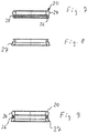
- Fig. 7
- a section through a radial seal,
- Fig. 8
- a section through a retaining ring for the radial seal and
- Fig. 9
- a section through the retaining ring and radial seal in the assembled state.
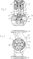
Die dargestellte Naßlaufkreiselpumpe weist einen Elektromotor 1 mit einem Motorgehäuse 2 auf, welches einen Stator 3 aufnimmt, in dem ein Rotor 4 drehbar gelagert ist, der eine Welle 5 aufweist, an deren pumpenseitigen Ende ein Laufrad 6 einer von diesem Elektromotor 1 angetriebenen Kreiselpumpe 7 angeordnet ist.The wet-running centrifugal pump shown has an
Die Kreiselpumpe 7 weist ein Pumpengehäuse 8 auf, das in der dargestellten Ausführungsform als Inline-Gehäuse ausgebildet ist und einen Saugstutzen 9 sowie einen Druckstutzen 10 aufweist, die über ein Spiralgehäuse 11 verbunden sind, in dem das Laufrad 6 in üblicher Weise angeordnet ist.The centrifugal pump 7 has a
Der Elektromotor 1 und die Kreiselplumpe 7 sind über Gehäuseflansche miteinander verbunden, die bei der dargestellten Ausführung mittels eines Klemmrings 12 form- und kraftschlüssig zusammengehalten werden.The
Das aus Elektromotor 1 und Kreiselpumpe 7 bestehende Pumpenaggregat ist als Naßläufer ausgebildet, d. h. der Rotor 4 des Elektromotors 1 läuft in einer Flüssigkeit, die durch ein Spaltrohr, hier in Form eines Spaltrohrtopfes 13, von dem die elektrischen Anschlüsse und Bauteile aufweisenden Stator 3 getrennt ist. Der Spaltrohrtopf 13 weist eine langegestreckte zylindrische Form auf und hat nahe seinem motorseitigen Ende einen Boden 14. Der zylindrische Körper des Spaltrohrtopfes 13 ist über den Boden 14 hinaus fortgesetzt und bildet dort Teil einer Zentrierhilfe, deren anderer Teil durch einen axial nach innen vorspringenden konusförmigen Gehäuseteil 15 des Motorgehäuses 2 gebildet wird, der durch den rohrförmigen, über den Boden 14 überstehenden Teil des Spaltrohrtopfes 13 teilweise überdeckt wird und auf diese Weise das motorseitige Ende des Spaltrohrtopfes 13 gegenüber dem Motorgehäuse 2 führt und zentriert. Darüber hinaus weist der Spaltrohrtopf 13 an seinem pumpenseitigen Ende einen umlaufenden und radial nach außen vorspringenden Kragen 16 auf, der die Topfstruktur am oberen Ende verstärkt und zugleich dazu dient, sich dort sammelnde Flüssigkeit gezielt abzuführen. Der Spaltrohrtopf 13 besteht aus Kunststoff und ist faserverstärkt in der vorliegenden Ausführung durch eine schraubenlinienförmig um den zylindrischen Teil des Topfes gewickelte Armierungsfasern. Das Spaltrohr, welches den Stator 3 mit den nicht im einzelnen dargestellten Statorwicklungen gegenüber den mit Permanentmagneten bestückten Rotor 4 trennt, erzeugt, da es aus Kunststoff ist, nur minimale Wirbelstromverluste, das den ohnehin hohen Wirkungsgrad des Permanentmotors weiter erhöht.The pump assembly consisting of
Innerhalb des Spaltrohrtopfes ist nahe des Bodens 14 ein motorseitiges Lager 17 für die Welle 3 vorgesehen, die eine zentrale Längsbohrung aufweist. Ein weiteres pumpenseitiges Lager 18 lagert die Welle 5 im Bereich zwischen den motorseitigen Teil und dem Laufrad 6. Das pumpenseitige Lager 18 ist in einer Lagerplatte 19 angeordnet, welche zwischen den Flanschen von Motorgehäuse 2 und Pumpengehäuse 8 formschlüssig und dicht eingegliedert ist und die zusammen mit dem Spaltrohrtopf 13 und einer dazwischen eingegliederten Radialrichtung 20 das Pumpengehäuse 8 hermetisch gegenüber dem Motorgehäuse 2, insbesondere dem den Stator 3 aufnehmenden Teil des Motorgehäuses 2 abtrennt.A motor-side bearing 17 for the shaft 3, which has a central longitudinal bore, is provided within the canned pot near the bottom 14. Another pump-
Die Lagerplatte 19 ist aus Edelstahl gebildet und erstreckt sich von ihrem umlaufenden Flansch 21 radial nach innen, schräg in das Pumpengehäuse 8 hineinlaufendend, um sich dann mit einem hohlzylindrischen Abschnitt 22 bis in das pumpenseitige Ende des Spaltrohrtopfes 3 zu erstrecken. Im Bereich dieses hohlzylindrischen Abschnitts 22 ist das pumpenseitige Lager 18 aufgenommen, welches ein kombiniertes Axial-/Radiallager ist. Innerhalb des hohlzylindrischen Abschnitts 22 ist das Radiallager festgelegt, in welchem die Welle 5 drehbar gelagert ist. Ein Axiallager ist durch die motorseitige Stirnfläche des Radiallagers in Verbindung mit einem drehfest auf der Welle 5 angeordneten Gegenlager 23 gebildet. Dieses Axiallager dient dazu, die hydraulisch bedingten Axialkräfte der Pumpe aufzunehmen.The bearing
Die Außenseite des hohlzylindrischen Abschnitts 22 bildet einen flächigen ringförmigen Dichtsitz für die zylindrische Innenfläche der Radialrichtung 20, deren Außenfläche durch eine radial vorspringende Dichtlippe 24 gebildet ist, welche an der Innenseite des Spaltrohrtopfes 13 anliegt. Wie die
Die Radialdichtung 20 besteht aus der eigentlichen im Querschnitt im Wesentlichen rechteckigen umlaufenden Dichtung mit der radial nach außen weisenden Dichtlippe 24. Sie weist einen axial über einen umlaufenden Steg 25 anschließend ebenfalls ringförmig umlaufenden Halteabschnitt 26 auf, der in eine umlaufende Nut eines aus Kunststoff bestehenden Halterings 27 eingreift, welcher, wie
Im Gegensatz zu
Der umlaufende Kragen 16 dient nicht nur zur Stabilisierung des pumpenseitigen Endes des Spaltrohrtopfes 13 sondern darüber hinaus auch als Tropfkante zur Abfuhr von sich dort möglicherweise ansammelnder Flüssigkeit. Da die Pumpe zum Betrieb mit waagerechter Welle bestimmt und ausgebildet ist, also so, wie sie in
Von dem in den
In
- 11
- ElektromotorElectric motor
- 22
- MotorgehäuseMotor housing
- 33
- Statorstator
- 44
- Rotorrotor
- 55
- Wellewave
- 66
- LaufradWheel
- 77
- KreiselpumpeCentrifugal pump
- 88th
- PumpengehäusePump housing
- 99
- SaugstutzenSuction port
- 1010
- DruckstutzenDischarge nozzle
- 1111
- SpiralgehäuseVolute casing
- 1212th
- KlemmringClamping ring
- 1313
- SpaltrohrtopfCanned pot
- 1414
- Boden von 13Floor of 13
- 1515
- konusförmiger Teil des Motorgehäusesconical part of the motor housing
- 1616
- Kragen von 13Collar of 13
- 1717
- bodenseitiges Lagerbottom bearing
- 1818th
- motorseitiges Lagerengine side bearing
- 1919
- LagerplatteBearing plate
- 2020th
- RadialdichtungRadial seal
- 2121
- Flansch der LagerplatteFlange of the bearing plate
- 2222
- hohlzylindrischer Abschnitt von 19hollow cylindrical section of 19
- 2323
-
Gegenlager auf der Welle 5Counter bearing on
shaft 5 - 2424
- DichtlippeSealing lip
- 2525
- Stegweb
- 2626
- HalteabschnittHolding section
- 2727
- HalteringRetaining ring
- 2828
- FlüssigkeitsabführöffnungLiquid discharge opening
- 2929
- Kanälechannels
- 3030
- Öffnungen an der Unterseite des MotorgehäusesOpenings on the underside of the engine case
- 3131
- SchraubenanschlüsseScrew connections
- 3232
- Anschlussconnection
Claims (13)
- A wet-running centrifugal pump with an electric motor (1) and with a centrifugal pump (7) which is driven thereby, wherein the electric motor (1) comprises a rotor (4) which is arranged within a stator (3), wherein a can pot (13) which carries a motor-side bearing (17) for the rotor (4) is provided between the rotor (4) and the stator (3), and with a bearing plate (19) which carries a pump-side bearing (18) for the rotor (4), wherein the bearing plate (19) is fixed on the housing side, and in the region of the bearing (18) immerses into the can pot (13), wherein at least one seal is provided between the can pot (13) and the bearing plate (19), the pump (7) is envisaged and designed for operation with a horizontally arranged shaft (5), at least one opening (28) for the discharge of fluid is provided in the motor housing (2) at the lower side of the motor housing (2), the can pot (13) close to or at its open end comprises a collar (16) which extends outwards from the tubular body of the can pot (13), and the at least one opening (28) is arranged axially in the region in which the collar also lies, characterised in that the at least one seal is a radial seal (20) between the can pot (13) and the bearing plate (19), and that the opening (28) is designed as a labyrinth channel for the discharge of fluid.
- A wet-running centrifugal pump according to claim 1, characterised in that the collar (16) is designed in a peripheral manner.
- A wet-running centrifugal pump according to one of the preceding claims, characterised in that can pot (13) is arranged in an axially floating manner.
- A wet-running centrifugal pump according to one of the preceding claims, characterised in that centring means (15) are provided, which on the housing side guide the closed end of the can pot (13).
- A wet-running centrifugal pump according to one of the preceding claims, characterised in that the bearing plate (19) is integrated between the motor housing and pump housing (2 and 8).
- wet-running centrifugal pump according to one of the preceding claims, characterised in that a component (27), in particular a ring (27) is provided, said component preferably being arranged on the bearing plate side between the part (22) of the bearing plate (19) which receives the bearing (18) and the open end of the can pot (13), said ring positively securing the at least one radial seal (20) in the axial direction.
- A wet-running centrifugal pump according to one of the preceding claims, characterised in that the at least one radial seal is formed by a radial sealing ring (20) which comprises a holding section (26) which is positively integrated in a corresponding holding recess of the component/ring (27).
- A wet-running centrifugal pump according to one of the preceding claims, characterised in that the can pot (13) consists of preferably fibre-reinforced plastic.
- A wet-running centrifugal pump according to one of the preceding claims, characterised in that the bearing plate (19) consists of metallic material, preferably stainless steel.
- A wet-running centrifugal pump according to one of the preceding claims, characterised in that the motor (1) is a permanent magnet motor (1) which is preferably controlled by a speed controller.
- A wet-running centrifugal pump according to one of the preceding claims, characterised in that the at least one radial seal (20) comprises a sealing lip (24) which is directed radially to the tubular part of the can pot (13) and comprises a radially inwardly directed, flat sealing seat on the bearing plate (19).
- A wet-running centrifugal pump according to one of the preceding claims, characterised in that the tubular part of the can pot (13) is extended beyond the pot base (14).
- A wet-running centrifugal pump according to one of the preceding claims, characterised in that the bearing plate (19) has a hollow-cylindrical section (22) which on the inside receives the bearing (18) and on whose outer side the radial seal (20) bears.
Priority Applications (1)
| Application Number | Priority Date | Filing Date | Title |
|---|---|---|---|
| EP15155953.1A EP2905472B1 (en) | 2011-12-23 | 2012-08-17 | Wet running circulation pump |
Applications Claiming Priority (3)
| Application Number | Priority Date | Filing Date | Title |
|---|---|---|---|
| EP11195636.3A EP2607707B2 (en) | 2011-12-23 | 2011-12-23 | Electric motor |
| EP15155953.1A EP2905472B1 (en) | 2011-12-23 | 2012-08-17 | Wet running circulation pump |
| EP12180810.9A EP2607710B1 (en) | 2011-12-23 | 2012-08-17 | Wet running circulation pump |
Related Parent Applications (2)
| Application Number | Title | Priority Date | Filing Date |
|---|---|---|---|
| EP12180810.9A Division EP2607710B1 (en) | 2011-12-23 | 2012-08-17 | Wet running circulation pump |
| EP12180810.9A Division-Into EP2607710B1 (en) | 2011-12-23 | 2012-08-17 | Wet running circulation pump |
Publications (2)
| Publication Number | Publication Date |
|---|---|
| EP2905472A1 EP2905472A1 (en) | 2015-08-12 |
| EP2905472B1 true EP2905472B1 (en) | 2020-03-04 |
Family
ID=47428663
Family Applications (2)
| Application Number | Title | Priority Date | Filing Date |
|---|---|---|---|
| EP15155953.1A Revoked EP2905472B1 (en) | 2011-12-23 | 2012-08-17 | Wet running circulation pump |
| EP12180810.9A Active EP2607710B1 (en) | 2011-12-23 | 2012-08-17 | Wet running circulation pump |
Family Applications After (1)
| Application Number | Title | Priority Date | Filing Date |
|---|---|---|---|
| EP12180810.9A Active EP2607710B1 (en) | 2011-12-23 | 2012-08-17 | Wet running circulation pump |
Country Status (5)
| Country | Link |
|---|---|
| US (1) | US9887603B2 (en) |
| EP (2) | EP2905472B1 (en) |
| CN (1) | CN104126074B (en) |
| PL (1) | PL2607710T3 (en) |
| WO (1) | WO2013092902A1 (en) |
Families Citing this family (9)
| Publication number | Priority date | Publication date | Assignee | Title |
|---|---|---|---|---|
| FR3029732B1 (en) | 2014-12-08 | 2018-03-02 | Renault S.A.S | COMPACT ELECTRIC MOTOR POWERTRAIN ARCHITECTURE FOR MOTOR VEHICLE. |
| JP6700674B2 (en) | 2015-05-21 | 2020-05-27 | 三菱重工サーマルシステムズ株式会社 | Motor housing for electric compressor and vehicle-mounted electric compressor using the same |
| EP3382206B1 (en) * | 2017-03-31 | 2020-12-16 | Grundfos Holding A/S | Pump assembly |
| PL3425221T3 (en) * | 2017-07-06 | 2020-05-18 | Grundfos Holding A/S | Pump bearing retainer |
| DE102018115952A1 (en) * | 2018-07-02 | 2020-01-02 | Ebm-Papst St. Georgen Gmbh & Co. Kg | Motor arrangement with a can |
| DE102019208910A1 (en) * | 2019-06-19 | 2020-12-24 | Bühler Motor GmbH | Electric motor |
| EP3763943A1 (en) * | 2019-07-10 | 2021-01-13 | Grundfos Holding A/S | Method for manufacturing a can |
| DE102020121707B3 (en) | 2020-08-19 | 2021-09-02 | Dr. Ing. H.C. F. Porsche Aktiengesellschaft | Electric machine with directly cooled stator |
| DE102021114571A1 (en) | 2021-06-07 | 2022-12-08 | Dr. Ing. H.C. F. Porsche Aktiengesellschaft | canned motor |
Citations (19)
| Publication number | Priority date | Publication date | Assignee | Title |
|---|---|---|---|---|
| NL136978C (en) | ||||
| DE1925887A1 (en) | 1968-05-22 | 1970-05-06 | Dumesnil Gerard Paul Louis | Device for connecting electrical lines |
| DE1802561A1 (en) | 1968-10-11 | 1970-05-27 | Licentia Gmbh | Hot water pump |
| DE1907379A1 (en) | 1969-02-14 | 1970-09-03 | Hanning Elektro Werke | Sealing ring |
| DE1613154A1 (en) | 1967-11-02 | 1971-08-05 | Hanning Elektro Werke | Electric motor for centrifugal pumps |
| DE2048467A1 (en) | 1970-10-02 | 1971-11-11 | Hanning Elektro Werke | Heating circulation pump |
| US3667870A (en) | 1971-01-04 | 1972-06-06 | Matsushita Electric Ind Co Ltd | Motor driven pump |
| DE2207647A1 (en) | 1972-02-18 | 1973-08-30 | Richard Halm | MOTOR FOR A LIQUID PUMP |
| FR2262433A1 (en) | 1974-02-23 | 1975-09-19 | Laing Nikolaus | |
| DE3247112C1 (en) | 1982-12-20 | 1984-07-19 | Schorch GmbH, 4050 Mönchengladbach | Electrical machine condensation water outlet closure bung - has separate head and shaft joined via pin |
| JPH06105501A (en) | 1992-09-18 | 1994-04-15 | Mayekawa Mfg Co Ltd | Can sealing structure of canned motor |
| DE19907561A1 (en) | 1998-06-04 | 1999-12-09 | Asmo Co Ltd | Electric wash pump and motor unit |
| DE19914579A1 (en) | 1999-03-31 | 2000-11-16 | Grundfos As | Centrifugal pump unit has adapter between motor and pump housings, sealing arrangements between adapter and pump housing and between adapter and slotted tube pot |
| DE19943862A1 (en) | 1999-09-13 | 2001-03-15 | Wilo Gmbh | Wet rotor pump with mounting plate |
| DE10144653A1 (en) | 2001-09-11 | 2003-04-03 | Ate Antriebstechnik Und Entwic | Permanently excited electromechanical machine for operating in liquids and gases, has an encapsulated/compound-filled stator fitted on a coil unit. |
| DE69724425T2 (en) | 1996-06-19 | 2004-03-11 | ITT Automotive Electrical Systems, Inc., Auburn Hills | WIPER-WINDOW WASHING MOTOR FOR USE IN A MOTOR VEHICLE |
| DE102004017418A1 (en) | 2004-04-08 | 2005-11-03 | Grundfos A/S | Method for producing a dimensionally stable, hollow-body-shaped element with a bottom region and use of such an element |
| EP2072827A1 (en) | 2007-12-17 | 2009-06-24 | Grundfos Management A/S | Canned motor pump |
| DE102010041925A1 (en) | 2010-10-04 | 2012-04-05 | Robert Bosch Gmbh | Vane pump |
Family Cites Families (16)
| Publication number | Priority date | Publication date | Assignee | Title |
|---|---|---|---|---|
| US3128712A (en) * | 1961-08-03 | 1964-04-14 | Allis Chalmers Mfg Co | Canned motor pump |
| US4786238A (en) * | 1984-12-20 | 1988-11-22 | Allied-Signal Inc. | Thermal isolation system for turbochargers and like machines |
| DE19624145A1 (en) * | 1996-06-18 | 1998-01-08 | Wilo Gmbh | Electric motor |
| DE19705974A1 (en) * | 1997-02-17 | 1998-08-20 | Wilo Gmbh | Electric motor for a pump or a fan |
| ATE370334T1 (en) * | 2004-04-02 | 2007-09-15 | Grundfos As | PUMP UNIT |
| US20060043916A1 (en) * | 2004-09-01 | 2006-03-02 | The Consortium, Llc | Motor system having multiple motor torque constants |
| CN2744863Y (en) * | 2004-11-09 | 2005-12-07 | 浙江工业大学 | Pipe flow type electric pump |
| CN2759039Y (en) * | 2004-11-09 | 2006-02-15 | 浙江工业大学 | Permanent magnet wet-electric pump |
| US7370865B2 (en) * | 2005-02-15 | 2008-05-13 | Cnh America Llc | Assembly including face seal sized to interference fit in housing |
| DE202005008288U1 (en) * | 2005-05-27 | 2005-08-04 | Harting Electric Gmbh & Co. Kg | Housing seal for plug connection, facilitates short-stroke latching of plug with counter-plug to give environmental-sealing of pluggable connection |
| EP1742334A1 (en) * | 2005-07-06 | 2007-01-10 | Rausch, Hartmuth | Compact drive |
| ATE470075T1 (en) * | 2005-09-24 | 2010-06-15 | Grundfos Management As | SUBMERSIBLE PUMP UNIT |
| PT2320092E (en) * | 2007-01-18 | 2014-02-12 | Grundfos Management As | Pump unit |
| ES2402667T5 (en) * | 2008-04-19 | 2016-06-28 | Grundfos Management A/S | Stator housing component for a sealed encapsulated motor |
| EP2148096B1 (en) * | 2008-07-25 | 2013-04-10 | Grundfos Management A/S | Centrifugal pump |
| CN201372933Y (en) * | 2009-02-20 | 2009-12-30 | 广东威灵电机制造有限公司 | Direct current brushless circulating water pump |
-
2012
- 2012-08-17 PL PL12180810T patent/PL2607710T3/en unknown
- 2012-08-17 EP EP15155953.1A patent/EP2905472B1/en not_active Revoked
- 2012-08-17 EP EP12180810.9A patent/EP2607710B1/en active Active
- 2012-12-20 WO PCT/EP2012/076462 patent/WO2013092902A1/en active Application Filing
- 2012-12-20 US US14/367,523 patent/US9887603B2/en active Active
- 2012-12-20 CN CN201280070597.6A patent/CN104126074B/en active Active
Patent Citations (19)
| Publication number | Priority date | Publication date | Assignee | Title |
|---|---|---|---|---|
| NL136978C (en) | ||||
| DE1613154A1 (en) | 1967-11-02 | 1971-08-05 | Hanning Elektro Werke | Electric motor for centrifugal pumps |
| DE1925887A1 (en) | 1968-05-22 | 1970-05-06 | Dumesnil Gerard Paul Louis | Device for connecting electrical lines |
| DE1802561A1 (en) | 1968-10-11 | 1970-05-27 | Licentia Gmbh | Hot water pump |
| DE1907379A1 (en) | 1969-02-14 | 1970-09-03 | Hanning Elektro Werke | Sealing ring |
| DE2048467A1 (en) | 1970-10-02 | 1971-11-11 | Hanning Elektro Werke | Heating circulation pump |
| US3667870A (en) | 1971-01-04 | 1972-06-06 | Matsushita Electric Ind Co Ltd | Motor driven pump |
| DE2207647A1 (en) | 1972-02-18 | 1973-08-30 | Richard Halm | MOTOR FOR A LIQUID PUMP |
| FR2262433A1 (en) | 1974-02-23 | 1975-09-19 | Laing Nikolaus | |
| DE3247112C1 (en) | 1982-12-20 | 1984-07-19 | Schorch GmbH, 4050 Mönchengladbach | Electrical machine condensation water outlet closure bung - has separate head and shaft joined via pin |
| JPH06105501A (en) | 1992-09-18 | 1994-04-15 | Mayekawa Mfg Co Ltd | Can sealing structure of canned motor |
| DE69724425T2 (en) | 1996-06-19 | 2004-03-11 | ITT Automotive Electrical Systems, Inc., Auburn Hills | WIPER-WINDOW WASHING MOTOR FOR USE IN A MOTOR VEHICLE |
| DE19907561A1 (en) | 1998-06-04 | 1999-12-09 | Asmo Co Ltd | Electric wash pump and motor unit |
| DE19914579A1 (en) | 1999-03-31 | 2000-11-16 | Grundfos As | Centrifugal pump unit has adapter between motor and pump housings, sealing arrangements between adapter and pump housing and between adapter and slotted tube pot |
| DE19943862A1 (en) | 1999-09-13 | 2001-03-15 | Wilo Gmbh | Wet rotor pump with mounting plate |
| DE10144653A1 (en) | 2001-09-11 | 2003-04-03 | Ate Antriebstechnik Und Entwic | Permanently excited electromechanical machine for operating in liquids and gases, has an encapsulated/compound-filled stator fitted on a coil unit. |
| DE102004017418A1 (en) | 2004-04-08 | 2005-11-03 | Grundfos A/S | Method for producing a dimensionally stable, hollow-body-shaped element with a bottom region and use of such an element |
| EP2072827A1 (en) | 2007-12-17 | 2009-06-24 | Grundfos Management A/S | Canned motor pump |
| DE102010041925A1 (en) | 2010-10-04 | 2012-04-05 | Robert Bosch Gmbh | Vane pump |
Non-Patent Citations (1)
| Title |
|---|
| "Rio-Eco® Baureihenheft", KSB AKTIENGESELLSCHAFT FRANKENTHAL, 25 May 2010 (2010-05-25), XP055265879 |
Also Published As
| Publication number | Publication date |
|---|---|
| PL2607710T3 (en) | 2015-08-31 |
| EP2607710A1 (en) | 2013-06-26 |
| EP2905472A1 (en) | 2015-08-12 |
| CN104126074B (en) | 2017-02-22 |
| US9887603B2 (en) | 2018-02-06 |
| US20150211525A1 (en) | 2015-07-30 |
| EP2607710B1 (en) | 2015-04-08 |
| WO2013092902A1 (en) | 2013-06-27 |
| CN104126074A (en) | 2014-10-29 |
Similar Documents
| Publication | Publication Date | Title |
|---|---|---|
| EP2905472B1 (en) | Wet running circulation pump | |
| EP3074632B1 (en) | Electric motor driven fluid pump, in particular for the forced lubrication of a manual transmission of a motor vehicle | |
| EP2072826B1 (en) | Rotor for a canned motor | |
| EP1768233B1 (en) | Airgap sleeve | |
| EP3374642B1 (en) | Electric axial-flow liquid pump for motor vehicle | |
| EP2610497B1 (en) | Pump power unit | |
| EP2708754A2 (en) | Pump | |
| EP1913262B1 (en) | Pump body, pump and a water supply household appliance | |
| DE10353566A1 (en) | jet propulsion | |
| DE10140613A1 (en) | Naßläuferpumpe | |
| EP2072827B1 (en) | Canned motor pump | |
| EP2546525B1 (en) | Circulation pump with spiral housing | |
| EP2002123B1 (en) | Fluid pump | |
| DE10064717A1 (en) | Method for operating a pump set | |
| EP2520806B1 (en) | Motor pump unit | |
| EP3085961B1 (en) | Multi-stage radial pump | |
| EP2990651B1 (en) | Pump casing | |
| EP2228538B1 (en) | Multi-layer circulation pump aggregate | |
| DE2901638B1 (en) | Centrifugal pump for liquids mixed with solids | |
| EP1148248A2 (en) | Pump housing | |
| DE10019820C2 (en) | Pump, in particular circulation pump for household machines such as dishwashers | |
| DE10012662A1 (en) | Coolant pump with an electronically commutated motor for IC engines, has coil body fastened to IC engine housing itself or to sealing flange located on IC engine housing | |
| DE102015210601A1 (en) | Impeller for a pump or turbine | |
| DE102022210734A1 (en) | Liquid pump, especially coolant pump | |
| DE19913632A1 (en) | Liquid ring pump |
Legal Events
| Date | Code | Title | Description |
|---|---|---|---|
| PUAI | Public reference made under article 153(3) epc to a published international application that has entered the european phase |
Free format text: ORIGINAL CODE: 0009012 |
|
| AC | Divisional application: reference to earlier application |
Ref document number: 2607710 Country of ref document: EP Kind code of ref document: P |
|
| AK | Designated contracting states |
Kind code of ref document: A1 Designated state(s): AL AT BE BG CH CY CZ DE DK EE ES FI FR GB GR HR HU IE IS IT LI LT LU LV MC MK MT NL NO PL PT RO RS SE SI SK SM TR |
|
| 17P | Request for examination filed |
Effective date: 20160210 |
|
| RBV | Designated contracting states (corrected) |
Designated state(s): AL AT BE BG CH CY CZ DE DK EE ES FI FR GB GR HR HU IE IS IT LI LT LU LV MC MK MT NL NO PL PT RO RS SE SI SK SM TR |
|
| STAA | Information on the status of an ep patent application or granted ep patent |
Free format text: STATUS: EXAMINATION IS IN PROGRESS |
|
| 17Q | First examination report despatched |
Effective date: 20171124 |
|
| GRAP | Despatch of communication of intention to grant a patent |
Free format text: ORIGINAL CODE: EPIDOSNIGR1 |
|
| STAA | Information on the status of an ep patent application or granted ep patent |
Free format text: STATUS: GRANT OF PATENT IS INTENDED |
|
| RIC1 | Information provided on ipc code assigned before grant |
Ipc: H02K 7/08 20060101ALN20190826BHEP Ipc: H02K 5/04 20060101ALI20190826BHEP Ipc: F04D 13/06 20060101ALI20190826BHEP Ipc: H02K 5/128 20060101ALI20190826BHEP Ipc: F04D 25/06 20060101AFI20190826BHEP Ipc: F04D 29/08 20060101ALI20190826BHEP Ipc: H02K 5/167 20060101ALI20190826BHEP |
|
| INTG | Intention to grant announced |
Effective date: 20190925 |
|
| GRAS | Grant fee paid |
Free format text: ORIGINAL CODE: EPIDOSNIGR3 |
|
| GRAA | (expected) grant |
Free format text: ORIGINAL CODE: 0009210 |
|
| STAA | Information on the status of an ep patent application or granted ep patent |
Free format text: STATUS: THE PATENT HAS BEEN GRANTED |
|
| AC | Divisional application: reference to earlier application |
Ref document number: 2607710 Country of ref document: EP Kind code of ref document: P |
|
| AK | Designated contracting states |
Kind code of ref document: B1 Designated state(s): AL AT BE BG CH CY CZ DE DK EE ES FI FR GB GR HR HU IE IS IT LI LT LU LV MC MK MT NL NO PL PT RO RS SE SI SK SM TR |
|
| REG | Reference to a national code |
Ref country code: GB Ref legal event code: FG4D Free format text: NOT ENGLISH |
|
| REG | Reference to a national code |
Ref country code: CH Ref legal event code: EP |
|
| REG | Reference to a national code |
Ref country code: AT Ref legal event code: REF Ref document number: 1240678 Country of ref document: AT Kind code of ref document: T Effective date: 20200315 |
|
| REG | Reference to a national code |
Ref country code: DE Ref legal event code: R096 Ref document number: 502012015839 Country of ref document: DE |
|
| REG | Reference to a national code |
Ref country code: IE Ref legal event code: FG4D Free format text: LANGUAGE OF EP DOCUMENT: GERMAN |
|
| PG25 | Lapsed in a contracting state [announced via postgrant information from national office to epo] |
Ref country code: NO Free format text: LAPSE BECAUSE OF FAILURE TO SUBMIT A TRANSLATION OF THE DESCRIPTION OR TO PAY THE FEE WITHIN THE PRESCRIBED TIME-LIMIT Effective date: 20200604 Ref country code: FI Free format text: LAPSE BECAUSE OF FAILURE TO SUBMIT A TRANSLATION OF THE DESCRIPTION OR TO PAY THE FEE WITHIN THE PRESCRIBED TIME-LIMIT Effective date: 20200304 Ref country code: RS Free format text: LAPSE BECAUSE OF FAILURE TO SUBMIT A TRANSLATION OF THE DESCRIPTION OR TO PAY THE FEE WITHIN THE PRESCRIBED TIME-LIMIT Effective date: 20200304 |
|
| REG | Reference to a national code |
Ref country code: NL Ref legal event code: MP Effective date: 20200304 |
|
| PG25 | Lapsed in a contracting state [announced via postgrant information from national office to epo] |
Ref country code: HR Free format text: LAPSE BECAUSE OF FAILURE TO SUBMIT A TRANSLATION OF THE DESCRIPTION OR TO PAY THE FEE WITHIN THE PRESCRIBED TIME-LIMIT Effective date: 20200304 Ref country code: GR Free format text: LAPSE BECAUSE OF FAILURE TO SUBMIT A TRANSLATION OF THE DESCRIPTION OR TO PAY THE FEE WITHIN THE PRESCRIBED TIME-LIMIT Effective date: 20200605 Ref country code: LV Free format text: LAPSE BECAUSE OF FAILURE TO SUBMIT A TRANSLATION OF THE DESCRIPTION OR TO PAY THE FEE WITHIN THE PRESCRIBED TIME-LIMIT Effective date: 20200304 Ref country code: SE Free format text: LAPSE BECAUSE OF FAILURE TO SUBMIT A TRANSLATION OF THE DESCRIPTION OR TO PAY THE FEE WITHIN THE PRESCRIBED TIME-LIMIT Effective date: 20200304 Ref country code: BG Free format text: LAPSE BECAUSE OF FAILURE TO SUBMIT A TRANSLATION OF THE DESCRIPTION OR TO PAY THE FEE WITHIN THE PRESCRIBED TIME-LIMIT Effective date: 20200604 |
|
| REG | Reference to a national code |
Ref country code: LT Ref legal event code: MG4D |
|
| PG25 | Lapsed in a contracting state [announced via postgrant information from national office to epo] |
Ref country code: NL Free format text: LAPSE BECAUSE OF FAILURE TO SUBMIT A TRANSLATION OF THE DESCRIPTION OR TO PAY THE FEE WITHIN THE PRESCRIBED TIME-LIMIT Effective date: 20200304 |
|
| PG25 | Lapsed in a contracting state [announced via postgrant information from national office to epo] |
Ref country code: ES Free format text: LAPSE BECAUSE OF FAILURE TO SUBMIT A TRANSLATION OF THE DESCRIPTION OR TO PAY THE FEE WITHIN THE PRESCRIBED TIME-LIMIT Effective date: 20200304 Ref country code: PT Free format text: LAPSE BECAUSE OF FAILURE TO SUBMIT A TRANSLATION OF THE DESCRIPTION OR TO PAY THE FEE WITHIN THE PRESCRIBED TIME-LIMIT Effective date: 20200729 Ref country code: CZ Free format text: LAPSE BECAUSE OF FAILURE TO SUBMIT A TRANSLATION OF THE DESCRIPTION OR TO PAY THE FEE WITHIN THE PRESCRIBED TIME-LIMIT Effective date: 20200304 Ref country code: RO Free format text: LAPSE BECAUSE OF FAILURE TO SUBMIT A TRANSLATION OF THE DESCRIPTION OR TO PAY THE FEE WITHIN THE PRESCRIBED TIME-LIMIT Effective date: 20200304 Ref country code: LT Free format text: LAPSE BECAUSE OF FAILURE TO SUBMIT A TRANSLATION OF THE DESCRIPTION OR TO PAY THE FEE WITHIN THE PRESCRIBED TIME-LIMIT Effective date: 20200304 Ref country code: SM Free format text: LAPSE BECAUSE OF FAILURE TO SUBMIT A TRANSLATION OF THE DESCRIPTION OR TO PAY THE FEE WITHIN THE PRESCRIBED TIME-LIMIT Effective date: 20200304 Ref country code: EE Free format text: LAPSE BECAUSE OF FAILURE TO SUBMIT A TRANSLATION OF THE DESCRIPTION OR TO PAY THE FEE WITHIN THE PRESCRIBED TIME-LIMIT Effective date: 20200304 Ref country code: SK Free format text: LAPSE BECAUSE OF FAILURE TO SUBMIT A TRANSLATION OF THE DESCRIPTION OR TO PAY THE FEE WITHIN THE PRESCRIBED TIME-LIMIT Effective date: 20200304 Ref country code: IS Free format text: LAPSE BECAUSE OF FAILURE TO SUBMIT A TRANSLATION OF THE DESCRIPTION OR TO PAY THE FEE WITHIN THE PRESCRIBED TIME-LIMIT Effective date: 20200704 |
|
| REG | Reference to a national code |
Ref country code: DE Ref legal event code: R026 Ref document number: 502012015839 Country of ref document: DE |
|
| PLBI | Opposition filed |
Free format text: ORIGINAL CODE: 0009260 |
|
| PLAX | Notice of opposition and request to file observation + time limit sent |
Free format text: ORIGINAL CODE: EPIDOSNOBS2 |
|
| 26 | Opposition filed |
Opponent name: WILO SE Effective date: 20201204 Opponent name: KSB SE & CO. KGAA Effective date: 20201204 |
|
| PG25 | Lapsed in a contracting state [announced via postgrant information from national office to epo] |
Ref country code: DK Free format text: LAPSE BECAUSE OF FAILURE TO SUBMIT A TRANSLATION OF THE DESCRIPTION OR TO PAY THE FEE WITHIN THE PRESCRIBED TIME-LIMIT Effective date: 20200304 |
|
| PG25 | Lapsed in a contracting state [announced via postgrant information from national office to epo] |
Ref country code: PL Free format text: LAPSE BECAUSE OF FAILURE TO SUBMIT A TRANSLATION OF THE DESCRIPTION OR TO PAY THE FEE WITHIN THE PRESCRIBED TIME-LIMIT Effective date: 20200304 Ref country code: SI Free format text: LAPSE BECAUSE OF FAILURE TO SUBMIT A TRANSLATION OF THE DESCRIPTION OR TO PAY THE FEE WITHIN THE PRESCRIBED TIME-LIMIT Effective date: 20200304 |
|
| PG25 | Lapsed in a contracting state [announced via postgrant information from national office to epo] |
Ref country code: MC Free format text: LAPSE BECAUSE OF FAILURE TO SUBMIT A TRANSLATION OF THE DESCRIPTION OR TO PAY THE FEE WITHIN THE PRESCRIBED TIME-LIMIT Effective date: 20200304 |
|
| REG | Reference to a national code |
Ref country code: CH Ref legal event code: PL |
|
| PG25 | Lapsed in a contracting state [announced via postgrant information from national office to epo] |
Ref country code: CH Free format text: LAPSE BECAUSE OF NON-PAYMENT OF DUE FEES Effective date: 20200831 Ref country code: LI Free format text: LAPSE BECAUSE OF NON-PAYMENT OF DUE FEES Effective date: 20200831 Ref country code: LU Free format text: LAPSE BECAUSE OF NON-PAYMENT OF DUE FEES Effective date: 20200817 |
|
| PLBB | Reply of patent proprietor to notice(s) of opposition received |
Free format text: ORIGINAL CODE: EPIDOSNOBS3 |
|
| REG | Reference to a national code |
Ref country code: BE Ref legal event code: MM Effective date: 20200831 |
|
| PG25 | Lapsed in a contracting state [announced via postgrant information from national office to epo] |
Ref country code: BE Free format text: LAPSE BECAUSE OF NON-PAYMENT OF DUE FEES Effective date: 20200831 Ref country code: IE Free format text: LAPSE BECAUSE OF NON-PAYMENT OF DUE FEES Effective date: 20200817 |
|
| REG | Reference to a national code |
Ref country code: AT Ref legal event code: MM01 Ref document number: 1240678 Country of ref document: AT Kind code of ref document: T Effective date: 20200817 |
|
| PG25 | Lapsed in a contracting state [announced via postgrant information from national office to epo] |
Ref country code: AT Free format text: LAPSE BECAUSE OF NON-PAYMENT OF DUE FEES Effective date: 20200817 |
|
| PGFP | Annual fee paid to national office [announced via postgrant information from national office to epo] |
Ref country code: IT Payment date: 20210831 Year of fee payment: 10 Ref country code: FR Payment date: 20210823 Year of fee payment: 10 |
|
| REG | Reference to a national code |
Ref country code: DE Ref legal event code: R103 Ref document number: 502012015839 Country of ref document: DE Ref country code: DE Ref legal event code: R064 Ref document number: 502012015839 Country of ref document: DE |
|
| RDAF | Communication despatched that patent is revoked |
Free format text: ORIGINAL CODE: EPIDOSNREV1 |
|
| PGFP | Annual fee paid to national office [announced via postgrant information from national office to epo] |
Ref country code: GB Payment date: 20210824 Year of fee payment: 10 Ref country code: DE Payment date: 20210824 Year of fee payment: 10 |
|
| RDAG | Patent revoked |
Free format text: ORIGINAL CODE: 0009271 |
|
| STAA | Information on the status of an ep patent application or granted ep patent |
Free format text: STATUS: PATENT REVOKED |
|
| REG | Reference to a national code |
Ref country code: CH Ref legal event code: PL |
|
| REG | Reference to a national code |
Ref country code: FI Ref legal event code: MGE |
|
| 27W | Patent revoked |
Effective date: 20211119 |
|
| GBPR | Gb: patent revoked under art. 102 of the ep convention designating the uk as contracting state |
Effective date: 20211119 |
|
| PG25 | Lapsed in a contracting state [announced via postgrant information from national office to epo] |
Ref country code: TR Free format text: LAPSE BECAUSE OF FAILURE TO SUBMIT A TRANSLATION OF THE DESCRIPTION OR TO PAY THE FEE WITHIN THE PRESCRIBED TIME-LIMIT Effective date: 20200304 Ref country code: MT Free format text: LAPSE BECAUSE OF FAILURE TO SUBMIT A TRANSLATION OF THE DESCRIPTION OR TO PAY THE FEE WITHIN THE PRESCRIBED TIME-LIMIT Effective date: 20200304 Ref country code: CY Free format text: LAPSE BECAUSE OF FAILURE TO SUBMIT A TRANSLATION OF THE DESCRIPTION OR TO PAY THE FEE WITHIN THE PRESCRIBED TIME-LIMIT Effective date: 20200304 |
|
| REG | Reference to a national code |
Ref country code: AT Ref legal event code: MA03 Ref document number: 1240678 Country of ref document: AT Kind code of ref document: T Effective date: 20211119 |
|
| PG25 | Lapsed in a contracting state [announced via postgrant information from national office to epo] |
Ref country code: MK Free format text: LAPSE BECAUSE OF FAILURE TO SUBMIT A TRANSLATION OF THE DESCRIPTION OR TO PAY THE FEE WITHIN THE PRESCRIBED TIME-LIMIT Effective date: 20200304 Ref country code: AL Free format text: LAPSE BECAUSE OF FAILURE TO SUBMIT A TRANSLATION OF THE DESCRIPTION OR TO PAY THE FEE WITHIN THE PRESCRIBED TIME-LIMIT Effective date: 20200304 |