EP2905108A1 - Frame for a machine - Google Patents
Frame for a machine Download PDFInfo
- Publication number
- EP2905108A1 EP2905108A1 EP15151875.0A EP15151875A EP2905108A1 EP 2905108 A1 EP2905108 A1 EP 2905108A1 EP 15151875 A EP15151875 A EP 15151875A EP 2905108 A1 EP2905108 A1 EP 2905108A1
- Authority
- EP
- European Patent Office
- Prior art keywords
- carriage
- base plate
- linear drive
- force
- frame
- Prior art date
- Legal status (The legal status is an assumption and is not a legal conclusion. Google has not performed a legal analysis and makes no representation as to the accuracy of the status listed.)
- Granted
Links
- 238000003466 welding Methods 0.000 claims abstract description 43
- 238000006073 displacement reaction Methods 0.000 claims abstract description 5
- 230000003313 weakening effect Effects 0.000 claims description 4
- 230000001052 transient effect Effects 0.000 claims 1
- 239000000725 suspension Substances 0.000 description 5
- 210000000056 organ Anatomy 0.000 description 3
- 238000005452 bending Methods 0.000 description 2
- 238000010409 ironing Methods 0.000 description 2
- 230000007704 transition Effects 0.000 description 2
- 238000006243 chemical reaction Methods 0.000 description 1
- 230000001419 dependent effect Effects 0.000 description 1
- 230000005489 elastic deformation Effects 0.000 description 1
- 238000004049 embossing Methods 0.000 description 1
- 238000004519 manufacturing process Methods 0.000 description 1
- 238000007620 mathematical function Methods 0.000 description 1
- 238000000034 method Methods 0.000 description 1
- 230000010355 oscillation Effects 0.000 description 1
- 230000003534 oscillatory effect Effects 0.000 description 1
- 238000002360 preparation method Methods 0.000 description 1
- 230000001105 regulatory effect Effects 0.000 description 1
- 230000003068 static effect Effects 0.000 description 1
- 238000003860 storage Methods 0.000 description 1
Images

Classifications
-
- B—PERFORMING OPERATIONS; TRANSPORTING
- B23—MACHINE TOOLS; METAL-WORKING NOT OTHERWISE PROVIDED FOR
- B23K—SOLDERING OR UNSOLDERING; WELDING; CLADDING OR PLATING BY SOLDERING OR WELDING; CUTTING BY APPLYING HEAT LOCALLY, e.g. FLAME CUTTING; WORKING BY LASER BEAM
- B23K37/00—Auxiliary devices or processes, not specially adapted to a procedure covered by only one of the preceding main groups
- B23K37/02—Carriages for supporting the welding or cutting element
- B23K37/0211—Carriages for supporting the welding or cutting element travelling on a guide member, e.g. rail, track
-
- B—PERFORMING OPERATIONS; TRANSPORTING
- B23—MACHINE TOOLS; METAL-WORKING NOT OTHERWISE PROVIDED FOR
- B23K—SOLDERING OR UNSOLDERING; WELDING; CLADDING OR PLATING BY SOLDERING OR WELDING; CUTTING BY APPLYING HEAT LOCALLY, e.g. FLAME CUTTING; WORKING BY LASER BEAM
- B23K20/00—Non-electric welding by applying impact or other pressure, with or without the application of heat, e.g. cladding or plating
- B23K20/10—Non-electric welding by applying impact or other pressure, with or without the application of heat, e.g. cladding or plating making use of vibrations, e.g. ultrasonic welding
-
- B—PERFORMING OPERATIONS; TRANSPORTING
- B23—MACHINE TOOLS; METAL-WORKING NOT OTHERWISE PROVIDED FOR
- B23K—SOLDERING OR UNSOLDERING; WELDING; CLADDING OR PLATING BY SOLDERING OR WELDING; CUTTING BY APPLYING HEAT LOCALLY, e.g. FLAME CUTTING; WORKING BY LASER BEAM
- B23K37/00—Auxiliary devices or processes, not specially adapted to a procedure covered by only one of the preceding main groups
- B23K37/02—Carriages for supporting the welding or cutting element
- B23K37/0247—Driving means
-
- B—PERFORMING OPERATIONS; TRANSPORTING
- B23—MACHINE TOOLS; METAL-WORKING NOT OTHERWISE PROVIDED FOR
- B23Q—DETAILS, COMPONENTS, OR ACCESSORIES FOR MACHINE TOOLS, e.g. ARRANGEMENTS FOR COPYING OR CONTROLLING; MACHINE TOOLS IN GENERAL CHARACTERISED BY THE CONSTRUCTION OF PARTICULAR DETAILS OR COMPONENTS; COMBINATIONS OR ASSOCIATIONS OF METAL-WORKING MACHINES, NOT DIRECTED TO A PARTICULAR RESULT
- B23Q11/00—Accessories fitted to machine tools for keeping tools or parts of the machine in good working condition or for cooling work; Safety devices specially combined with or arranged in, or specially adapted for use in connection with, machine tools
- B23Q11/001—Arrangements compensating weight or flexion on parts of the machine
- B23Q11/0014—Arrangements compensating weight or flexion on parts of the machine using static reinforcing elements, e.g. pre-stressed ties
-
- B—PERFORMING OPERATIONS; TRANSPORTING
- B29—WORKING OF PLASTICS; WORKING OF SUBSTANCES IN A PLASTIC STATE IN GENERAL
- B29C—SHAPING OR JOINING OF PLASTICS; SHAPING OF MATERIAL IN A PLASTIC STATE, NOT OTHERWISE PROVIDED FOR; AFTER-TREATMENT OF THE SHAPED PRODUCTS, e.g. REPAIRING
- B29C65/00—Joining or sealing of preformed parts, e.g. welding of plastics materials; Apparatus therefor
- B29C65/02—Joining or sealing of preformed parts, e.g. welding of plastics materials; Apparatus therefor by heating, with or without pressure
- B29C65/08—Joining or sealing of preformed parts, e.g. welding of plastics materials; Apparatus therefor by heating, with or without pressure using ultrasonic vibrations
-
- B—PERFORMING OPERATIONS; TRANSPORTING
- B29—WORKING OF PLASTICS; WORKING OF SUBSTANCES IN A PLASTIC STATE IN GENERAL
- B29C—SHAPING OR JOINING OF PLASTICS; SHAPING OF MATERIAL IN A PLASTIC STATE, NOT OTHERWISE PROVIDED FOR; AFTER-TREATMENT OF THE SHAPED PRODUCTS, e.g. REPAIRING
- B29C66/00—General aspects of processes or apparatus for joining preformed parts
- B29C66/006—Preventing damaging, e.g. of the parts to be joined
- B29C66/0062—Preventing damaging, e.g. of the parts to be joined of the joining tool, e.g. avoiding wear of the joining tool
-
- B—PERFORMING OPERATIONS; TRANSPORTING
- B29—WORKING OF PLASTICS; WORKING OF SUBSTANCES IN A PLASTIC STATE IN GENERAL
- B29C—SHAPING OR JOINING OF PLASTICS; SHAPING OF MATERIAL IN A PLASTIC STATE, NOT OTHERWISE PROVIDED FOR; AFTER-TREATMENT OF THE SHAPED PRODUCTS, e.g. REPAIRING
- B29C66/00—General aspects of processes or apparatus for joining preformed parts
- B29C66/80—General aspects of machine operations or constructions and parts thereof
- B29C66/81—General aspects of the pressing elements, i.e. the elements applying pressure on the parts to be joined in the area to be joined, e.g. the welding jaws or clamps
- B29C66/816—General aspects of the pressing elements, i.e. the elements applying pressure on the parts to be joined in the area to be joined, e.g. the welding jaws or clamps characterised by the mounting of the pressing elements, e.g. of the welding jaws or clamps
-
- B—PERFORMING OPERATIONS; TRANSPORTING
- B29—WORKING OF PLASTICS; WORKING OF SUBSTANCES IN A PLASTIC STATE IN GENERAL
- B29C—SHAPING OR JOINING OF PLASTICS; SHAPING OF MATERIAL IN A PLASTIC STATE, NOT OTHERWISE PROVIDED FOR; AFTER-TREATMENT OF THE SHAPED PRODUCTS, e.g. REPAIRING
- B29C66/00—General aspects of processes or apparatus for joining preformed parts
- B29C66/80—General aspects of machine operations or constructions and parts thereof
- B29C66/82—Pressure application arrangements, e.g. transmission or actuating mechanisms for joining tools or clamps
- B29C66/824—Actuating mechanisms
- B29C66/8242—Pneumatic or hydraulic drives
-
- B—PERFORMING OPERATIONS; TRANSPORTING
- B29—WORKING OF PLASTICS; WORKING OF SUBSTANCES IN A PLASTIC STATE IN GENERAL
- B29C—SHAPING OR JOINING OF PLASTICS; SHAPING OF MATERIAL IN A PLASTIC STATE, NOT OTHERWISE PROVIDED FOR; AFTER-TREATMENT OF THE SHAPED PRODUCTS, e.g. REPAIRING
- B29C66/00—General aspects of processes or apparatus for joining preformed parts
- B29C66/80—General aspects of machine operations or constructions and parts thereof
- B29C66/83—General aspects of machine operations or constructions and parts thereof characterised by the movement of the joining or pressing tools
- B29C66/832—Reciprocating joining or pressing tools
- B29C66/8322—Joining or pressing tools reciprocating along one axis
-
- B—PERFORMING OPERATIONS; TRANSPORTING
- B29—WORKING OF PLASTICS; WORKING OF SUBSTANCES IN A PLASTIC STATE IN GENERAL
- B29C—SHAPING OR JOINING OF PLASTICS; SHAPING OF MATERIAL IN A PLASTIC STATE, NOT OTHERWISE PROVIDED FOR; AFTER-TREATMENT OF THE SHAPED PRODUCTS, e.g. REPAIRING
- B29C66/00—General aspects of processes or apparatus for joining preformed parts
- B29C66/90—Measuring or controlling the joining process
- B29C66/92—Measuring or controlling the joining process by measuring or controlling the pressure, the force, the mechanical power or the displacement of the joining tools
- B29C66/922—Measuring or controlling the joining process by measuring or controlling the pressure, the force, the mechanical power or the displacement of the joining tools by measuring the pressure, the force, the mechanical power or the displacement of the joining tools
- B29C66/9221—Measuring or controlling the joining process by measuring or controlling the pressure, the force, the mechanical power or the displacement of the joining tools by measuring the pressure, the force, the mechanical power or the displacement of the joining tools by measuring the pressure, the force or the mechanical power
- B29C66/92211—Measuring or controlling the joining process by measuring or controlling the pressure, the force, the mechanical power or the displacement of the joining tools by measuring the pressure, the force, the mechanical power or the displacement of the joining tools by measuring the pressure, the force or the mechanical power with special measurement means or methods
-
- B—PERFORMING OPERATIONS; TRANSPORTING
- B29—WORKING OF PLASTICS; WORKING OF SUBSTANCES IN A PLASTIC STATE IN GENERAL
- B29C—SHAPING OR JOINING OF PLASTICS; SHAPING OF MATERIAL IN A PLASTIC STATE, NOT OTHERWISE PROVIDED FOR; AFTER-TREATMENT OF THE SHAPED PRODUCTS, e.g. REPAIRING
- B29C66/00—General aspects of processes or apparatus for joining preformed parts
- B29C66/90—Measuring or controlling the joining process
- B29C66/92—Measuring or controlling the joining process by measuring or controlling the pressure, the force, the mechanical power or the displacement of the joining tools
- B29C66/922—Measuring or controlling the joining process by measuring or controlling the pressure, the force, the mechanical power or the displacement of the joining tools by measuring the pressure, the force, the mechanical power or the displacement of the joining tools
- B29C66/9231—Measuring or controlling the joining process by measuring or controlling the pressure, the force, the mechanical power or the displacement of the joining tools by measuring the pressure, the force, the mechanical power or the displacement of the joining tools by measuring the displacement of the joining tools
- B29C66/92311—Measuring or controlling the joining process by measuring or controlling the pressure, the force, the mechanical power or the displacement of the joining tools by measuring the pressure, the force, the mechanical power or the displacement of the joining tools by measuring the displacement of the joining tools with special measurement means or methods
-
- B—PERFORMING OPERATIONS; TRANSPORTING
- B29—WORKING OF PLASTICS; WORKING OF SUBSTANCES IN A PLASTIC STATE IN GENERAL
- B29C—SHAPING OR JOINING OF PLASTICS; SHAPING OF MATERIAL IN A PLASTIC STATE, NOT OTHERWISE PROVIDED FOR; AFTER-TREATMENT OF THE SHAPED PRODUCTS, e.g. REPAIRING
- B29C66/00—General aspects of processes or apparatus for joining preformed parts
- B29C66/90—Measuring or controlling the joining process
- B29C66/92—Measuring or controlling the joining process by measuring or controlling the pressure, the force, the mechanical power or the displacement of the joining tools
- B29C66/924—Measuring or controlling the joining process by measuring or controlling the pressure, the force, the mechanical power or the displacement of the joining tools by controlling or regulating the pressure, the force, the mechanical power or the displacement of the joining tools
- B29C66/9241—Measuring or controlling the joining process by measuring or controlling the pressure, the force, the mechanical power or the displacement of the joining tools by controlling or regulating the pressure, the force, the mechanical power or the displacement of the joining tools by controlling or regulating the pressure, the force or the mechanical power
Definitions
- the present invention relates to a frame for a machine, for example a stamping, embossing or welding machine, in particular for an ultrasonic welding machine, with a serving as a base for the welding machine base plate, a rigidly connected to the base plate column, along which a guide rail provided is, and a linear drive, with which a force can be applied by a working organ acting as a sonotrode of the welding machine on a workpiece positionable on the base plate.
- a frame for a machine for example a stamping, embossing or welding machine, in particular for an ultrasonic welding machine, with a serving as a base for the welding machine base plate, a rigidly connected to the base plate column, along which a guide rail provided is, and a linear drive, with which a force can be applied by a working organ acting as a sonotrode of the welding machine on a workpiece positionable on the base plate.
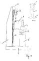
- the illustrated frame 20 has a base plate 2, on which a workpiece 6 to be welded can be arranged and which is rigidly connected to an upright column 1.
- a cantilever arm 12 At the top of the column 1, a cantilever arm 12 is mounted comparatively rigid, which in turn carries a drive 3 for generating the required welding force F.
- the welding force F of the drive 3 is transmitted via a slide 9, which is displaceably guided along a guide rail 10 on the column 1 in the vertical direction, to a working organ serving as a sonotrode 5, which is supported by the carriage 9 and the vibration of a fourth is excited to the carriage 9 to high-frequency oscillations.
- FIG Fig. 2 is shown schematically.
- the column 1 has been bent to the left due to the application of the welding force F on the workpiece 6, which undesirably results in that the head of the sonotrode 5 is no longer in the desired manner over the entire surface on the surface of the workpiece 6, such as especially in the enlarged detail "A" of Fig. 2 can be recognized.
- such unparallelism between sonotrode 5 and workpiece 6 can undesirably be at the expense of the result of the work and, in particular, at the expense of the weld seam quality.
- Another frame is also from the document DE 83 16 643 U1 known.
- This frame has features of the upper handle of claim 1 and in particular has a trained in the manner of a gallows suspension device to which a suspension element a spindle box is suspended.
- a gallows suspension device to which a suspension element a spindle box is suspended.
- the suspension device is mounted only by means of a roller on the running surface of a beam-like support element.
- no lifting forces can be removed via the gallows-like suspension device, ie no forces that can arise as a result of a force applied by a tool.
- the invention is therefore based on the object to provide a frame for a welding machine, in which a bending of the frame, which is due to lifting forces, which are caused in response to forces applied to a workpiece, is minimized.
- the linear drive is therefore not supported by the column of the frame of the welding machine but by an additional support, which can be formed for example by a support member which is supported by the base plate, which will be discussed in more detail later.
- this support can be made relatively stiff, for example, by appropriate dimensioning of said support member, so that this deformed relatively little due to the welding force generated by the linear drive; Nevertheless, any deformations of the support or the support member can not be completely excluded, especially in the vertical direction, which is why it is provided according to the invention to avoid unwanted forced voltages in the linear drive as well as in this carrying carriage, that this carriage is guided displaceably along the guide rail extends in a vertical direction along the column.
- the carriage together with the linear drive can therefore yield guided in the vertical direction when the support bearing the carriage is slightly deflected in a vertical upward direction due to a welding force generated by the linear drive.
- the column is not deflected as a result of the welding force, which avoids possible non-parallelism between the sonotrode and the workpiece in the desired manner.
- the working member in the form of the sonotrode with the actuator of the linear actuator is aligned or is arranged in extension of the travel of the same. If it is mentioned here that the working member is aligned with the linear drive or its travel or other positions, this means that there is essentially no offset between the working member and the linear drive or its travel or the other positions. It will be like this good as no offset moments generated, so that the carriage is not tilted. Thus, the desired alignment between the working member and the workpiece can be substantially maintained even under load.
- the support for the carriage, which carries the linear drive can be formed in accordance with the above statements by a support member which is connected to the base plate;
- the support in question it would also be possible for the support in question to be formed, for example, by a cantilever beam, a bracket or the like, which is an integral part of the production line in which the welding frame is located.
- the base plate together with the pillar can stand on a table, whereas the support is formed by an on-site stationary structural member such as a wall projection or a support bracket or the like.
- the support can slidably support the carriage in the horizontal direction so as to be able to compensate for any differences in movement between the stationary structural member and the carriage.
- the carriage may be coupled via a horizontal slotted guide with the support, which is formed by a guided in a slot pin.
- the support is formed by a support member which carries both with the carriage, which carries the linear drive, as well as with the Base plate is preferably hingedly connected.
- the support member is thus an integral part of the frame according to the invention, so that the welding frame can basically be set up at any location and used.
- the support member may for example be formed by a relatively rigid rod or carrier, which connects the base plate with the carriage which carries the linear drive.
- the rod or support By virtue of the rod or support, the slide is thus to a certain extent coupled to the base plate, so that the slide can deform only as part of the elastic deformation of the rod or of the carrier as a result of a welding force generated by the linear drive.
- the support member is formed by at least one preferably substantially C-shaped bracket, which in the region of its two free Ends hinged to the carriage or the base plate is connected.
- the at least one essentially C-shaped bracket may preferably have a web section and a first and a second flange section, wherein the web section runs parallel to the column of the frame and the two flange sections protrude from the web section in a manner of a ridge.
- the first flange portion is hingedly connected at its free end to the carriage for the linear drive
- the second flange portion is hingedly connected at its free end to the base plate.
- the second flange portion is received by the base plate, for which purpose the base plate can form a receiving cavity into which the respective bracket extends with its second flange portion.
- the working space between the carriage and the base plate is thus in a sense partially surrounded by the at least one substantially C-shaped bracket, so that the working space is free from interference by the bracket.
- the frame has two substantially C-shaped bracket whose web sections flank the column of the frame on both sides. Each of the two brackets thus receives approximately the same load, whereby any deformations perpendicular to the ironing plane due to unbalanced load conditions is counteracted.
- the working member is aligned in the form of sonotrode with the actuator of the linear drive or in extension of the travel of the same is arranged.
- it may be provided to ensure only vertical movement components of the carriage and to minimize bending of the frame that the articulated joints of the support member with the carriage and the base plate are aligned with the travel of the linear drive.
- the linear drive and the working member and the connection points of the support member with the carriage and the base plate are substantially on a straight line, since this can be achieved that caused by the linear drive welding force largely implemented in a purely vertical component movement of the carriage becomes.
- the sonotrode is driven by a vibrating structure, which is also displaceably guided along the guide rail, for example via a second carriage, which in turn carries the sonotrode. It is thus only a single guide rail needed to realize the slidable storage of the two carriages along the column of the frame can.
- a deformation measuring device such as a strain gauge is provided on the support member, which is preferably in the region of weakening of the support member or one of the bracket.
- the deformation measuring device is set up to provide a deformation variable of the support member of a force control device representative of the force applied by the linear drive so that it can take into account the deformation variable or a force variable derived therefrom as a controlled variable in the context of force regulation for the linear drive.
- the support member will deform all the more with increasing welding force, so that the deformation of the support member for the applied welding force is representative.
- the weight of the two slides, the linear drive and the oscillatory structure including the sonotrode is removed via the support member in the unloaded state.
- different sonotrodes and Vibrating structures can be used, this leads to the fact that in the unloaded state, the support structure undergoes a different strong or large pre-deformation.
- the force control device is further adapted to calibrate the deformation amount provided by the deformation measuring device in dependence on a pre-deformation of the support member. The force control device is thus to a certain extent set up to carry out a tare function and thus a zero adjustment of the deformation measuring device.
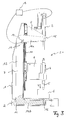
- the frame 20 for a welding machine serving as a base for the welding machine base plate 2, which is shown here in a partially broken-away view and serves to receive a workpiece 6. Furthermore, the frame 20 has an upright column 1, which is rigidly connected to the base plate 2. On the column 1, a guide rail 10 is mounted, which extends in the longitudinal direction of the column 1 in the vertical direction. The guide rail 10 is used here, on the one hand, the displaceable mounting of a first carriage 8 for a linear drive 3 in the region of the upper end of the support 1 and a second carriage 9 for a vibrating structure 4 for a sonotrode 5 in a work area between the first carriage 8 and the base plate. 2
- the first carriage 8 is displaceably guided along the guide rail 10 and carries a linear drive 3, which may, for example, be a spindle drive, a piston-cylinder unit or a linear motor and which serves to move onto the workpiece 6 via the working member serving sonotrode 5 to apply a welding force F.
- a linear drive 3 which may, for example, be a spindle drive, a piston-cylinder unit or a linear motor and which serves to move onto the workpiece 6 via the working member serving sonotrode 5 to apply a welding force F.
- the linear actuator 3 is not rigidly connected via a cantilever with the column 1; Rather, it is inventively provided that the linear drive 3 is mounted displaceably in the vertical direction on the column 1.
- the first carriage 8 is supported by a support, which in the embodiment shown here by two C-shaped bracket. 7 is formed, which flank the column 1 of the frame 20 on both sides.
- Each of the two substantially C-shaped bracket 7 in this case has a web portion 13 and a first and a second flange portion 14a, 14b, which protrude from the web portion 13 and are formed integrally therewith.
- the first flange portion 14a of the respective bracket 7 is hinged at its free end at a junction 15 with the first carriage 8, for example by means of a bolt connection.
- the second flange portion 14b is articulated at its free end at a junction 16 with the base plate 2, for example by means of a bolt connection, for which he hineinzreckt into a receiving cavity 11, which forms the base plate 2.
- the two brackets 7 are thus by the base plate 2 in vertical Direction supported by these are hinged to the base plate 2.
- the two brackets 7 thus the first carriage 8 and the base plate 2 are coupled together, with the result that the two brackets 7 counteract a force-induced displacement of the first carriage 8 by the linear drive 3, but this does not mean that the first carriage 8 no displacement experiences.
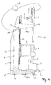
- the free ends of the two ironing flanges 14a, 14b are spread apart in the vertical direction parallel to the column 1, when a welding force F is transmitted through the linear drive 3 via the second carriage 9 and the vibrating structure 4 supported therefrom on the working member 5.
- the lifting reaction force which is caused in response to the NASAwn on the workpiece 6 welding force F, introduced via the bracket 7 as a tensile force in the base plate 2, which due to the articulated connection of the two flange portions 14a, 14b with the carriage 8 or the base plate 2 is possible.
- the two articulated connection points 15, 16 may thus be, for example, bolt connections or any other types of connection, provided that these forces can be transferred to the brackets 7 and from these to the base plate 2.
- the free end of the upper bracket flange 14a experiences exclusively a component of movement in the vertical direction, it is provided in the illustrated preferred embodiment that the working member 5 is aligned with the linear drive 3 and its travel and that the articulated connection points 15, 16 of the two Flanges 14a, 14b are aligned with the first carriage 8 and the base plate 2 with the travel of the linear drive 3.
- bracket 7 are supported by the first carriage 8 in the horizontal direction on the column 1, so that the bracket 7 are held in the desired position.
- the first carriage 8 thus forms a monovalent or displaceable support for the two brackets 7, which prevents the bracket 7 from tipping over the connection point 16 with the base plate, which for the bracket 7 in the static sense a bivalent or articulated Support forms.
- a deformation measuring device in the form of a strain gauge 17 is provided on at least one of the brackets 7 in the illustrated embodiment.
- the strain gauge 17 is arranged in the transition region between the upper bracket flange 14a and the hoop web 13 and thus in a region in which relatively large relative deformations take place.
- the bracket 7 is targeted in the mentioned transition region with a weakening 18th Mistake.
- the deformation variable detected by the deformation measuring device 17 is representative of the welding force F applied by the linear drive 3, wherein the relationship between deformation and welding force F can be stored in a look-up table.
- the deformation amount detected by the deformation measuring device 17 is now made available to a force control device 19 which is set up to take into account the deformation variable or a force variable derived therefrom as a controlled variable in the context of a force control for the linear drive 3.
- the force control device 19 thus compares the deformation quantity or a force variable derived therefrom with a setpoint value of the welding force F in order to determine a manipulated variable for regulating the linear drive 3 as a function of the difference between the setpoint value and the controlled variable.
- the support structure may have different strengths in the unloaded state or undergoes large pre-deformations. Since these pre-deformations are also detected by the deformation measuring device 17, it is therefore provided in the illustrated embodiment that the force control device 19 is further configured to calibrate the deformation amount provided by the deformation measuring device 17 as a function of a pre-deformation of the brackets 7. The force control device 19 is thus to a certain extent set up to carry out a tare function and thus a zero adjustment of the deformation measuring device.
Abstract
Die vorliegende Erfindung betrifft ein Gestell für eine Schweißmaschine mit einer Grundplatte und einer damit biegesteif verbundenen Säule, an der eine Führungsschiene angebracht ist. Ferner weist das Gestell einen Linearantrieb zum Aufbringen einer Kraft von einem Arbeitsorgan auf ein auf der Grundplatte positionierbares Werkstück auf, welcher von einem Schlitten getragen wird, der entlang der Führungsschiene verschieblich geführt ist. Des Weiteren ist ein Auflager vorgesehen, das den Schlitten trägt und einer kraftbedingten Verschiebung des Schlittens durch den Linearantrieb entgegenwirkt.The present invention relates to a frame for a welding machine with a base plate and a column rigidly connected thereto, to which a guide rail is attached. Furthermore, the frame has a linear drive for applying a force from a working member to a positionable on the base plate workpiece, which is supported by a carriage which is guided displaceably along the guide rail. Furthermore, a support is provided which carries the carriage and counteracts a force-induced displacement of the carriage by the linear drive.
Description
Die vorliegende Erfindung betrifft ein Gestell für eine Maschine, beispielsweise eine Stanz-, Präge- oder Schweißmaschine, insbesondere für eine Ultraschall-Schweißmaschine, mit einer als Standfuß für die Schweißmaschine dienenden Grundplatte, einer mit der Grundplatte biegesteif verbundenen Säule, entlang derer eine Führungsschiene vorgesehen ist, und einem Linearantrieb, mit dem eine Kraft von einer als Arbeitsorgan dienenden Sonotrode der Schweißmaschine auf ein auf der Grundplatte positionierbares Werkstück aufgebracht werden kann.The present invention relates to a frame for a machine, for example a stamping, embossing or welding machine, in particular for an ultrasonic welding machine, with a serving as a base for the welding machine base plate, a rigidly connected to the base plate column, along which a guide rail provided is, and a linear drive, with which a force can be applied by a working organ acting as a sonotrode of the welding machine on a workpiece positionable on the base plate.
Solch ein an sich bekanntes Gestell ist in den
Wird nun mit Hilfe des Antriebs 3 über die Sonotrode 5 die erforderliche Schweißkraft F auf das Werkstück 6 aufgebracht, so kann dies dazu führen, dass sich das Gestell 20 und insbesondere die Säule 1 elastisch verformt und verbiegt, wie dies in der
Ein anderes Gestell ist ferner aus der Druckschrift
Der Erfindung liegt somit die Aufgabe zugrunde, ein Gestell für eine Schweißmaschine zu schaffen, bei dem eine Verbiegung des Gestells, die auf abhebende Kräfte zurückzuführen ist, welche als Reaktion zu auf ein Werkstück aufgebachten Kräften verursacht werden, minimiert ist.The invention is therefore based on the object to provide a frame for a welding machine, in which a bending of the frame, which is due to lifting forces, which are caused in response to forces applied to a workpiece, is minimized.
Diese Aufgabe wird mit einem Gestell mit den Merkmalen des Anspruchs 1 und insbesondere dadurch gelöst, dass der Schlitten den Linearantrieb trägt, dass das Arbeitsorgan mit dem Stellweg des Linearantriebs fluchtet, und dass das Auflager derart ausgebildet ist, dass es einer kraftbedingten Verschiebung des Schlittens infolge einer Kraftaufbringung durch den Linearantrieb auf ein auf der Grundplatte positionierbares Werkstück entgegenwirkt.This object is achieved with a frame with the features of claim 1 and in particular in that the carriage carries the linear drive, that the working member is aligned with the travel of the linear drive, and that the support is designed such that there is a force-related displacement of the carriage due counteracts a force application by the linear drive to a positionable on the base workpiece.
Erfindungsgemäß wird der Linearantrieb also nicht von der Säule des Gestells der Schweißmaschine sondern von einem zusätzlichen Auflager getragen, welches beispielsweise durch ein Stützglied gebildet werden kann, das von der Grundplatte getragen wird, worauf später noch genauer eingegangen wird. Zwar kann dieses Auflager beispielsweise durch entsprechende Dimensionierung des genannten Stützglieds verhältnismäßig steif ausgebildet werden, so dass sich dieses infolge der von dem Linearantrieb erzeugten Schweißkraft verhältnismäßig wenig verformt; nichtsdestotrotz lassen sich etwaige Verformungen des Auflagers bzw. des Stützglieds insbesondere in vertikaler Richtung nicht vollkommen ausschließen, weshalb es zur Vermeidung unerwünschter Zwangsspannungen in dem Linearantrieb sowie in dem diesen tragenden Schlitten erfindungsgemäß vorgesehen ist, dass dieser Schlitten verschieblich entlang der Führungsschiene geführt ist, die sich in vertikaler Richtung entlang der Säule erstreckt. Der Schlitten mitsamt dem Linearantrieb kann daher in vertikaler Richtung geführt ausweichen, wenn das den Schlitten tragende Auflager geringfügig in vertikaler Richtung nach oben infolge einer von dem Linearantrieb erzeugten Schweißkraft ausgelenkt wird. Die Säule wird infolge der Schweißkraft hingegen nicht ausgelenkt, wodurch in der gewünschten Weise etwaige Unparallelitäten zwischen Sonotrode und Werkstück vermieden werden.According to the invention, the linear drive is therefore not supported by the column of the frame of the welding machine but by an additional support, which can be formed for example by a support member which is supported by the base plate, which will be discussed in more detail later. Although this support can be made relatively stiff, for example, by appropriate dimensioning of said support member, so that this deformed relatively little due to the welding force generated by the linear drive; Nevertheless, any deformations of the support or the support member can not be completely excluded, especially in the vertical direction, which is why it is provided according to the invention to avoid unwanted forced voltages in the linear drive as well as in this carrying carriage, that this carriage is guided displaceably along the guide rail extends in a vertical direction along the column. The carriage together with the linear drive can therefore yield guided in the vertical direction when the support bearing the carriage is slightly deflected in a vertical upward direction due to a welding force generated by the linear drive. By contrast, the column is not deflected as a result of the welding force, which avoids possible non-parallelism between the sonotrode and the workpiece in the desired manner.
Um sicherzustellen, dass der Schlitten, der den Linearantrieb trägt, infolge der von dem Linearantrieb erzeugten Schweißkraft eine weitestgehend nur in vertikaler Richtung orientierte Bewegungskomponente erfährt, ist es des Weiteren vorgesehen, dass das Arbeitsorgan in Form der Sonotrode mit dem Stellglied des Linearantriebs fluchtet bzw. in Verlängerung des Stellwegs desselben angeordnet ist. Sofern hier davon die Rede ist, dass das Arbeitsorgan mit dem Linearantrieb bzw. dessen Stellweg oder mit anderen Positionen fluchtet, so bedeutet dies, dass im Wesentlichen kein Versatz zwischen dem Arbeitsorgan und dem Linearantrieb bzw. dessen Stellweg oder den anderen Positionen existiert. Es werden somit so gut wie keine Versatzmomente erzeugt, so dass der Schlitten nicht verkantet. Somit kann die gewünschte Ausrichtung zwischen Arbeitsorgan und Werkstück selbst unter Last im Wesentlichen beibehalten werden.To ensure that the carriage, which carries the linear drive, as a result of the welding force generated by the linear drive largely oriented only in the vertical direction undergoes movement component, it is further provided that the working member in the form of the sonotrode with the actuator of the linear actuator is aligned or is arranged in extension of the travel of the same. If it is mentioned here that the working member is aligned with the linear drive or its travel or other positions, this means that there is essentially no offset between the working member and the linear drive or its travel or the other positions. It will be like this good as no offset moments generated, so that the carriage is not tilted. Thus, the desired alignment between the working member and the workpiece can be substantially maintained even under load.
Nachfolgend wird nun auf vorteilhafte Ausführungsformen der Erfindung eingegangen, wobei sich weitere Ausführungsformen auch aus den Unteransprüchen, der Figurenbeschreibung sowie den Zeichnungen ergeben können.Hereinafter, advantageous embodiments of the invention will be discussed, with further embodiments may also result from the dependent claims, the description of the figures and the drawings.
Zwar kann das Auflager für den Schlitten, der den Linearantrieb trägt, entsprechend den voranstehenden Ausführungen durch ein Stützglied gebildet werden, das mit der Grundplatte verbunden ist; gemäß einer einfachen Ausführungsform wäre es jedoch ebenfalls möglich, dass das in Rede stehende Auflager beispielsweise durch einen Kragträger, eine Konsole oder dergleichen gebildet wird, der bzw. die fester Bestandteil der Fertigungsstraße ist, in der sich das Schweißgestell befindet. Beispielweise kann die Grundplatte mitsamt der Säule auf einem Tisch stehen, wohingegen das Auflager durch ein bauseits ortsfestes Konstruktionsglied wie beispielweise einen Mauervorsprung oder eine Stützenkonsole oder dergleichen gebildet wird. In diesem Falle kann das Auflager den Schlitten in horizontaler Richtung verschieblich lagern, um so etwaige Bewegungsunterschiede zwischen dem ortfesten Konstruktionsglied und dem Schlitten ausgleichen zu können. Beispielsweise kann der Schlitten über eine horizontale Kulissenführung mit dem Auflager gekoppelt sein, welche durch einen in einem Schlitz geführten Zapfen gebildet wird.Although the support for the carriage, which carries the linear drive can be formed in accordance with the above statements by a support member which is connected to the base plate; However, according to a simple embodiment, it would also be possible for the support in question to be formed, for example, by a cantilever beam, a bracket or the like, which is an integral part of the production line in which the welding frame is located. For example, the base plate together with the pillar can stand on a table, whereas the support is formed by an on-site stationary structural member such as a wall projection or a support bracket or the like. In this case, the support can slidably support the carriage in the horizontal direction so as to be able to compensate for any differences in movement between the stationary structural member and the carriage. For example, the carriage may be coupled via a horizontal slotted guide with the support, which is formed by a guided in a slot pin.
Um jedoch bei der Aufstellung des Schweißgestells von äußeren Randbedingungen unabhängig zu sein, ist es entsprechend den voranstehenden Ausführungen gemäß einer bevorzugten Ausführungsform vorgesehen, dass das Auflager durch ein Stützglied gebildet wird, das sowohl mit dem Schlitten, der den Linearantrieb trägt, als auch mit der Grundplatte vorzugsweise gelenkig verbunden ist. Das Stützglied ist somit integraler Bestandteil des erfindungsgemäßen Gestells, so dass das Schweißgestell im Grunde genommen an beliebigen Orten aufgestellt werden und zum Einsatz kommen kann.However, in order to be independent of external boundary conditions in the preparation of the welding frame, it is provided according to the above embodiments according to a preferred embodiment, that the support is formed by a support member which carries both with the carriage, which carries the linear drive, as well as with the Base plate is preferably hingedly connected. The support member is thus an integral part of the frame according to the invention, so that the welding frame can basically be set up at any location and used.
Gemäß einer einfachen Ausführungsform kann das Stützglied beispielsweise durch einen verhältnismäßig starren Stab bzw. Träger gebildet werden, welcher die Grundplatte mit dem Schlitten, der den Linearantrieb trägt, verbindet. Durch den Stab bzw. Träger wird somit gewissermaßen der Schlitten mit der Grundplatte gekoppelt, so dass der Schlitten infolge einer von dem Linearantrieb erzeugten Schweißkraft sich nur im Rahmen der elastischen Verformung des Stabs bzw. des Trägers verformen kann.According to a simple embodiment, the support member may for example be formed by a relatively rigid rod or carrier, which connects the base plate with the carriage which carries the linear drive. By virtue of the rod or support, the slide is thus to a certain extent coupled to the base plate, so that the slide can deform only as part of the elastic deformation of the rod or of the carrier as a result of a welding force generated by the linear drive.
Da ein derartiger linearer Stab bzw. Träger jedoch den Arbeitsraum zwischen dem Schlitten und der Grundplatte beeinträchtigen kann, ist es gemäß einer bevorzugten Ausführungsform vorgesehen, dass das Stützglied durch zumindest einen vorzugsweise im Wesentlichen C-förmigen Bügel gebildet wird, welcher im Bereich seiner beiden freien Enden gelenkig mit dem Schlitten bzw. der Grundplatte verbunden ist. Vorzugsweise kann dabei der zumindest eine im Wesentlichen C-förmige Bügel einen Stegabschnitt und einen ersten sowie einen zweiten Flanschabschnitt aufweisen, wobei der Stegabschnitt parallel zu der Säule des Gestells verläuft und die beiden Flanschabschnitte kragartig von dem Stegabschnitt abstehen. In diesem Falle ist der erste Flanschabschnitt an seinem freien Ende mit dem Schlitten für den Linearantrieb gelenkig verbunden, wohingegen der zweite Flanschabschnitt an seinem freien Ende mit der Grundplatte gelenkig verbunden ist. Vorzugsweise wird dabei der zweite Flanschabschnitt von der Grundplatte aufgenommen, wozu die Grundplatte einen Aufnahmehohlraum ausbilden kann, in den sich der jeweilige Bügel mit seinem zweiten Flanschabschnitt hineinerstreckt. Der Arbeitsraum zwischen dem Schlitten und der Grundplatte wird somit gewissermaßen von dem zumindest einen im Wesentlichen C-förmigen Bügel teilweise umgeben, so dass der Arbeitsraum frei von Beeinträchtigungen durch den Bügel ist.However, since such a linear rod or carrier may affect the working space between the carriage and the base plate, it is provided according to a preferred embodiment, that the support member is formed by at least one preferably substantially C-shaped bracket, which in the region of its two free Ends hinged to the carriage or the base plate is connected. In this case, the at least one essentially C-shaped bracket may preferably have a web section and a first and a second flange section, wherein the web section runs parallel to the column of the frame and the two flange sections protrude from the web section in a manner of a ridge. In this case, the first flange portion is hingedly connected at its free end to the carriage for the linear drive, whereas the second flange portion is hingedly connected at its free end to the base plate. Preferably, the second flange portion is received by the base plate, for which purpose the base plate can form a receiving cavity into which the respective bracket extends with its second flange portion. The working space between the carriage and the base plate is thus in a sense partially surrounded by the at least one substantially C-shaped bracket, so that the working space is free from interference by the bracket.
Zwar kann es gemäß einer Ausführungsform ausreichend sein, den Schlitten und die Grundplatte über nur einen einzigen Bügel miteinander zu verbinden; da dies jedoch zu unsymmetrischen Belastungszuständen in dem Gestell führen kann, ist es gemäß einer bevorzugten Ausführungsform vorgesehen, dass das Gestell über zwei im Wesentlichen C-förmige Bügel verfügt, deren Stegabschnitte die Säule des Gestells beiderseitig beflanken. Jeder der beiden Bügel nimmt somit annähernd die gleiche Last auf, wodurch etwaigen Verformungen senkrecht zur Bügelebene infolge unsymmetrischer Belastungszustände entgegengewirkt wird.While it may be sufficient according to an embodiment, to connect the carriage and the base plate with each other via a single bracket; However, since this can lead to unbalanced load conditions in the frame, it is provided according to a preferred embodiment, that the frame has two substantially C-shaped bracket whose web sections flank the column of the frame on both sides. Each of the two brackets thus receives approximately the same load, whereby any deformations perpendicular to the ironing plane due to unbalanced load conditions is counteracted.
Um sicherzustellen, dass der Schlitten, der den Linearantrieb trägt, infolge der von dem Linearantrieb erzeugten Schweißkraft eine weitestgehend nur in vertikaler Richtung orientierte Bewegungskomponente erfährt, ist es entsprechend den voranstehenden Erläuterungen vorgesehen, dass das Arbeitsorgan in Form der Sonotrode mit dem Stellglied des Linearantriebs fluchtet bzw. in Verlängerung des Stellwegs desselben angeordnet ist. Zusätzlich kann es zur Sicherstellung ausschließlich vertikaler Bewegungskomponenten des Schlittens und zur Minimierung einer Verbiegung des Gestells vorgesehen sein, dass die gelenkigen Verbindungsstellen des Stützglieds mit dem Schlitten und der Grundplatte mit dem Stellweg des Linearantriebs fluchten. Mit anderen Worten befinden sich also der Linearantrieb und das Arbeitsorgan sowie die Verbindungsstellen des Stützglieds mit dem Schlitten und der Grundplatte im Wesentlichen auf einer Geraden, da hierdurch erreicht werden kann, dass eine durch den Linearantrieb hervorgerufene Schweißkraft weitestgehend in eine rein vertikale Bewegungskomponente des Schlittens umgesetzt wird.To ensure that the carriage, which carries the linear drive, as a result of the welding force generated by the linear drive largely oriented only in the vertical direction undergoes movement component, it is provided according to the above explanations that the working member is aligned in the form of sonotrode with the actuator of the linear drive or in extension of the travel of the same is arranged. In addition, it may be provided to ensure only vertical movement components of the carriage and to minimize bending of the frame that the articulated joints of the support member with the carriage and the base plate are aligned with the travel of the linear drive. In other words, therefore, the linear drive and the working member and the connection points of the support member with the carriage and the base plate are substantially on a straight line, since this can be achieved that caused by the linear drive welding force largely implemented in a purely vertical component movement of the carriage becomes.
Gemäß einer weiteren Ausführungsform ist es vorgesehen, dass die Sonotrode von einem Schwinggebilde angetrieben, das ebenfalls entlang der Führungsschiene verschieblich geführt ist, und zwar beispielsweise über einen zweiten Schlitten, der seinerseits die Sonotrode trägt. Es wird somit nur eine einzige Führungsschiene benötigt, um die verschiebliche Lagerung der beiden Schlitten entlang der Säule des Gestells realisieren zu können.According to a further embodiment, it is provided that the sonotrode is driven by a vibrating structure, which is also displaceably guided along the guide rail, for example via a second carriage, which in turn carries the sonotrode. It is thus only a single guide rail needed to realize the slidable storage of the two carriages along the column of the frame can.
Gemäß noch einer weiteren Ausführungsform ist es vorgesehen, dass eine Verformungsmesseinrichtung wie beispielsweise ein Dehnmessstreifen an dem Stützglied vorgesehen ist, die sich vorzugsweise im Bereich einer Schwächung des Stützglieds bzw. einer der Bügel befindet. Die Verformungsmesseinrichtung ist dabei eingerichtet, um eine für die von dem Linearantrieb aufgebrachte Kraft repräsentative Verformungsgröße des Stützglieds einer Kraftregeleinrichtung zur Verfügung zu stellen, so dass diese die Verformungsgröße oder eine daraus abgeleitete Kraftgröße als Regelgröße im Rahmen einer Kraftregelung für den Linearantrieb berücksichtigen kann. So wird sich nämlich das Stützglied mit zunehmender Schweißkraft umso mehr verformen, so dass die Verformung des Stützglieds für die aufgebrachte Schweißkraft repräsentativ ist. Um die tatsächlich aufgebrachte Schweißkraft ermitteln zu können, bedarf es daher keiner indirekter Messverfahren, die beispielsweise zur Bestimmung der Schweißkraft auf den Motorstrom zurückgreifen, wenn der Linearantrieb beispielsweise als Linearmotor oder Spindeltrieb realisiert ist; vielmehr besteht eine direkte Beziehung zwischen der Verformung des Stützglieds und der aufgebrachten Schweißkraft. Diese Beziehung kann in der Kraftregeleinrichtung oder in der Verformungsmesseinrichtung als Nachschlagetabelle oder mathematische Funktion hinterlegt sein, so dass aus der Verformung des Stützglieds direkt eine Aussage über die aktuelle Schweißkraft getroffen werden kann, so dass diese im Rahmen einer geschlossenen Regelschleife als Regelgröße bei einer Kraftregelung des Linearantriebs berücksichtigt werden kann.According to yet another embodiment, it is provided that a deformation measuring device such as a strain gauge is provided on the support member, which is preferably in the region of weakening of the support member or one of the bracket. The deformation measuring device is set up to provide a deformation variable of the support member of a force control device representative of the force applied by the linear drive so that it can take into account the deformation variable or a force variable derived therefrom as a controlled variable in the context of force regulation for the linear drive. Thus, the support member will deform all the more with increasing welding force, so that the deformation of the support member for the applied welding force is representative. In order to be able to determine the welding force actually applied, therefore, no indirect measuring methods are needed which, for example, use the motor current to determine the welding force when the linear drive is realized, for example, as a linear motor or spindle drive; rather, there is a direct relationship between the deformation of the support member and the applied welding force. This relationship can be stored in the force control device or in the deformation measuring device as a look-up table or mathematical function, so that from the deformation of the support member directly a statement about the current welding force can be made so that they as a controlled variable in a closed-loop control in a force control of Linear actuator can be considered.
Wie aus den voranstehenden Ausführungen hervorgeht, wird im unbelasteten Zustand das Gewicht der beiden Schlitten, des Linearantriebs und des Schwinggebildes einschließlich des der Sonotrode über das Stützglied abgetragen. Da je nach Einsatzzweck der Schweißmaschine unterschiedliche Sonotroden und Schwinggebilde zum Einsatz kommen können, führt dies dazu, dass im unbelasteten Zustand das Stützgebilde eine unterschiedlich starke bzw. große Vorverformung erfährt. Da diese Vorverformung auch von der Verformungsmesseinrichtung erfasst wird, ist es daher gemäß einer weiteren Ausführungsform vorgesehen, dass die Kraftregeleinrichtung ferner eingerichtet ist, um die von der Verformungsmesseinrichtung zur Verfügung gestellte Verformungsgröße in Abhängigkeit einer Vorverformung des Stützglieds zu kalibrieren. Die Kraftregeleinrichtung ist somit gewissermaßen eingerichtet, um eine Tara-Funktion und somit einen Nullabgleich der Verformungsmesseinrichtung durchzuführen.As is apparent from the foregoing, the weight of the two slides, the linear drive and the oscillatory structure including the sonotrode is removed via the support member in the unloaded state. Depending on the purpose of the welding machine different sonotrodes and Vibrating structures can be used, this leads to the fact that in the unloaded state, the support structure undergoes a different strong or large pre-deformation. Since this pre-deformation is also detected by the deformation measuring device, it is therefore provided according to a further embodiment, that the force control device is further adapted to calibrate the deformation amount provided by the deformation measuring device in dependence on a pre-deformation of the support member. The force control device is thus to a certain extent set up to carry out a tare function and thus a zero adjustment of the deformation measuring device.
Nachfolgend wird die Erfindung nun rein beispielhaft unter Bezugnahme auf die
- Fig. 1
- ein dem Grunde nach bekanntes Gestell für eine Schweißmaschine im unbelasteten Zustand;
- Fig. 2
- das Gestell der
Fig. 1 im belasteten Zustand; - Fig. 3
- eine Seitenansicht eines erfindungsgemäßen Gestells im unbelasteten Zustand; und
- Fig. 4
- das Gestell der
Fig. 3 im belasteten Zustand.
- Fig. 1
- a basically known frame for a welding machine in the unloaded state;
- Fig. 2
- the frame of the
Fig. 1 in the loaded condition; - Fig. 3
- a side view of a frame according to the invention in the unloaded state; and
- Fig. 4
- the frame of the
Fig. 3 in the loaded condition.
Wie der
Wie bereits angedeutet ist der erste Schlitten 8 entlang der Führungsschiene 10 verschieblich geführt und trägt einen Linearantrieb 3, bei dem es sich beispielsweise um einen Spindeltrieb, eine Kolbenzylindereinheit oder einen Linearmotor handeln kann und welcher dazu dient, um auf das Werkstück 6 über die als Arbeitsorgan dienende Sonotrode 5 eine Schweißkraft F aufzubringen. Im Unterschied zu dem an sich bekannten Schweißgestell gemäß
Um trotz dieser Verschieblichkeit mit Hilfe des Linearantriebs 3 auf das Werkstück 6 die erforderliche Schweißkraft F aufbringen zu können, ist es erfindungsgemäß vorgesehen, dass der erste Schlitten 8 von einem Auflager getragen wird, das in der hier dargestellten Ausführungsform durch zwei C-förmige Bügel 7 gebildet wird, die die Säule 1 des Gestells 20 beiderseits beflanken. Jeder der beiden im Wesentlichen C-förmigen Bügel 7 weist dabei einen Stegabschnitt 13 und einen ersten sowie einen zweiten Flanschabschnitt 14a, 14b auf, die kragartig von dem Stegabschnitt 13 abstehen und einstückig mit diesem ausgebildet sind. Der erste Flanschabschnitt 14a des jeweiligen Bügels 7 ist dabei an seinem freien Ende an einer Verbindungsstelle 15 mit dem ersten Schlitten 8 beispielsweise mittels einer Bolzenverbindung gelenkig verbunden. Gleichermaßen ist auch der zweite Flanschabschnitt 14b an seinem freien Ende an einer Verbindungsstelle 16 mit der Grundplatte 2 beispielsweise mittels einer Bolzenverbindung gelenkig verbunden, wozu er sich in einen Aufnahmehohlraum 11 hineinstreckt, den die Grundplatte 2 ausbildet. Die beiden Bügel 7 werden somit durch die Grundplatte 2 in vertikaler Richtung abgestützt, indem diese an der Grundplatte 2 gelenkig angebracht sind. Durch die beiden Bügel 7 sind somit der erste Schlitten 8 und die Grundplatte 2 miteinander gekoppelt, was zur Folge hat, dass die beiden Bügel 7 einer kraftbedingten Verschiebung des ersten Schlittens 8 durch den Linearantrieb 3 entgegenwirken, was jedoch nicht heißt, dass der erste Schlitten 8 keine Verschiebung erfährt. Vielmehr werden die freien Enden der beiden Bügelflansche 14a, 14b in vertikaler Richtung parallel zur Säule 1 auseinandergespreizt, wenn durch den Linearantrieb 3 eine Schweißkraft F über den zweiten Schlitten 9 und das davon getragene Schwinggebilde 4 auf das Arbeitsorgan 5 übertragen wird. Mit anderen Worten wird also die abhebende Reaktionskraft, welche als Reaktion zu der auf das Werkstück 6 aufgebachten Schweißkraft F verursacht wird, über die Bügel 7 als Zugkraft in die Grundplatte 2 eingeleitet, was aufgrund der gelenkigen Verbindung der beiden Flanschabschnitte 14a, 14b mit dem Schlitten 8 bzw. der Grundplatte 2 möglich ist. Bei den beiden gelenkigen Verbindungsstellen 15, 16 kann es sich somit beispielsweise um Bolzenverbindungen oder beliebige andere Verbindungsarten handeln, sofern sich mit diesen abhebende Kräfte auf die Bügel 7 und von diesen auf die Grundplatte 2 übertragen lassen.In order to be able to apply the required welding force F in spite of this mobility with the aid of the
Damit hierbei das freie Ende des oberen Bügelflanschs 14a ausschließlich eine Bewegungskomponente in vertikaler Richtung erfährt, ist es bei der dargestellten bevorzugten Ausführungsform vorgesehen, dass das Arbeitsorgan 5 mit dem Linearantrieb 3 bzw. dessen Stellweg fluchtet und dass auch die gelenkigen Verbindungsstellen 15, 16 der beiden Flansche 14a, 14b mit dem ersten Schlitten 8 bzw. der Grundplatte 2 mit dem Stellweg des Linearantriebs 3 fluchten. Sofern hier davon die Rede ist, dass das Arbeitsorgan 5 mit dem Linearantrieb 3 bzw. dessen Stellweg fluchtet, so bedeutet dies, dass im Wesentlichen kein Versatz zwischen dem Arbeitsorgan 5 und dem Linearantrieb 3 bzw. dessen Stellweg existiert; Durch den Linearantrieb 3 werden somit keine oder nur geringe Kraftkomponenten senkrecht zu dessen Stellweg hervorgerufen, was in der gewünschten Weise zur Folge hat, dass das freie Ende des oberen Bügelflanschs 14a ausschließlich eine Bewegungskomponente in vertikaler Richtung erfährt. Damit durch diese vertikale Bewegungskomponente keine unerwünschten Zwangsspannungen in dem Linearantrieb 3 bzw. in dem den Linearantrieb 3 tragenden ersten Schlitten 8 hervorgerufen werden, ist der erste Schlitten 8 in der erfindungsgemäßen Art und Weise verschieblich an der Führungsschiene 10 gelagert, so dass dieser um das gleiche Maß in vertikaler Richtung versetzt wird wie das freie Ende des oberen Bügelflanschs 14a. Davon abgesehen werden die Bügel 7 durch den ersten Schlitten 8 in horizontaler Richtung an der Säule 1 abgestützt, so dass die Bügel 7 in der gewünschten Position gehalten werden. Der erste Schlitten 8 bildet somit für die beiden Bügel 7 im statischen Sinne ein einwertiges bzw. verschiebliches Auflager, das die Bügel 7 daran hindert, um die Verbindungstelle 16 mit der Grundplatte umzukippen, welche für die Bügel 7 im statischen Sinne ein zweiwertiges bzw. gelenkiges Auflager bildet.Thus, in this case, the free end of the
Zwar wäre es dem Prinzip nach ebenfalls möglich, die beiden Verbindungsstellen 15, 16 anstelle über C-förmige Bügel, direkt mittels eines Stabs oder Trägers gelenkig miteinander zu verbinden. Hierdurch würde jedoch der Arbeitsraum zwischen dem ersten Schlitten 8 und der Grundplatte 2 beeinträchtigt werden, weshalb gemäß der dargestellten Ausführungsform zwei C-förmigen Bügeln 7 Vorrang zu geben ist.Although it would also be the principle according to the two connecting
Um die von dem Linearantrieb 3 auf das Werkstück 6 ausgeübte Schweißkraft F bestimmen zu können, ist in der dargestellten Ausführungsform an zumindest einem der Bügel 7 eine Verformungsmesseinrichtung in Form eines Dehnmessstreifens 17 vorgesehen. In der dargestellten Ausführungsform ist der Dehnmessstreifen 17 dabei im Übergangsbereich zwischen dem oberen Bügelflansch 14a und dem Bügelsteg 13 und somit in einem Bereich angeordnet, in dem verhältnismäßig große Relativverformungen stattfinden. Um derartige Relativverformungen für die Verformungsmesseinrichtung 17 noch wahrnehmbarer zu machen, ist der Bügel 7 in dem genannten Übergangsbereich gezielt mit einer Schwächung 18 versehen. Die von der Verformungsmesseinrichtung 17 erfasste Verformungsgröße ist dabei für die von dem Linearantrieb 3 aufgebrachte Schweißkraft F repräsentativ, wobei die Beziehung zwischen Verformung und Schweißkraft F in einer Nachschlagetabelle hinterlegt sein kann.In order to be able to determine the welding force F exerted by the
In der dargestellten Ausführungsform wird nun die von der Verformungsmesseinrichtung 17 erfasste Verformungsgröße einer Kraftregeleinrichtung 19 zur Verfügung gestellt, welche derart eingerichtet ist, um die Verformungsgröße oder eine daraus abgeleitete Kraftgröße als Regelgröße im Rahmen einer Kraftregelung für den Linearantrieb 3 zu berücksichtigen. Die Kraftregeleinrichtung 19 vergleicht also die Verformungsgröße oder eine daraus abgeleitete Kraftgröße mit einem Sollwert der Schweißkraft F, um in Abhängigkeit der Differenz zwischen dem Sollwert und der Regelgröße eine Stellgröße zur Regelung des Linearantriebs 3 zu bestimmen.In the illustrated embodiment, the deformation amount detected by the
Da im unbelasteten Zustand das Gewicht der beiden Schlitten 8,9, des Linearantriebs 3 und des Schwinggebildes 4 einschließlich der Sonotrode 5 über das Stützglied abgetragen wird, kann es in Abhängigkeit des verwandten Sonotrodentyps und Schwinggebildes dazu kommen, dass das Stützgebilde im unbelasteten Zustand unterschiedlich starke bzw. große Vorverformungen erfährt. Da diese Vorverformungen auch von der Verformungsmesseinrichtung 17 erfasst werden, ist es daher in der dargestellten Ausführungsform vorgesehen, dass die Kraftregeleinrichtung 19 ferner eingerichtet ist, um die von der Verformungsmesseinrichtung 17 zur Verfügung gestellte Verformungsgröße in Abhängigkeit einer Vorverformung der Bügel 7 zu kalibrieren. Die Kraftregeleinrichtung 19 ist somit gewissermaßen eingerichtet, um eine Tara-Funktion und somit einen Nullabgleich der Verformungsmesseinrichtung durchzuführen.Since the weight of the two
- 11
- Säulepillar
- 22
- Grundplattebaseplate
- 33
- Linearantrieblinear actuator
- 44
- Schwinggebildeoscillating structure
- 55
- Arbeitsorgan bzw. SonotrodeWorking organ or sonotrode
- 66
- Werkstückworkpiece
- 77
- Bügelhanger
- 88th
- erster Schlittenfirst sled
- 99
- zweiter Schlittensecond sled
- 1010
- Führungsschieneguide rail
- 1111
- Aufnahmeholraum in 2Recording room in 2
- 1212
- Kragarmcantilever
- 1313
- Steg von 7Footbridge of 7
- 14a, 14b14a, 14b
- oberer bzw. unterer Flansch von 7upper or lower flange of 7
- 1515
- obere Verbindungsstelleupper joint
- 1616
- untere Verbindungsstellelower joint
- 1717
- VerformungsmesseinrichtungDeformation measuring device
- 1818
- Schwächungweakening
- 1919
- KraftregeleinrichtungForce control
- 2020
- Gestellframe
- FF
- Schweißkraftwelding force
Claims (11)
dadurch gekennzeichnet, dass
das Auflager durch ein bauseits ortsfestes Konstruktionsglied, beispielweise durch einen Mauervorsprung, eine Stützenkonsole oder einen bauseits instationären Kragträger, gebildet wird, wobei der Schlitten (8) vorzugsweise in horizontaler Richtung verschieblich durch das Konstruktionsglied abgestützt wird.Frame according to claim 1,
characterized in that
the support is formed by an on-site stationary structural member, for example by a wall projection, a support bracket or an on-site transient cantilever beam, wherein the carriage (8) is preferably slidably supported in the horizontal direction by the structural member.
dadurch gekennzeichnet, dass das Auflager durch ein Stützglied gebildet wird, das mit sowohl mit dem Schlitten (8) als auch mit der Grundplatte (2) vorzugsweise gelenkig verbunden ist.Frame according to claim 1,
characterized in that the support is formed by a support member, which is preferably articulated to both the carriage (8) and the base plate (2).
dadurch gekennzeichnet, dass dass Stützglied durch zumindest einen vorzugsweise im Wesentlichen C-förmigen Bügel (7) gebildet wird, welcher im Bereich seiner beiden freien Enden gelenkig mit dem Schlitten (8) bzw. mit der Grundplatte (2) verbunden ist.Frame according to claim 2,
characterized in that the support member by at least one preferably substantially C-shaped bracket (7) is formed, which is connected in the region of its two free ends articulated to the carriage (8) and with the base plate (2).
dadurch gekennzeichnet, dass der zumindest eine vorzugsweise im Wesentlichen C-förmige Bügel (7) einen Stegabschnitt (13) und einen ersten sowie einen zweiten Flanschabschnitt (14a, 14b) aufweist, wobei der Stegabschnitt (13) parallel zu der Säule (1) des Gestells (20) verläuft und die beiden Flanschabschnitte (14a, 14b) kragartig von dem Stegabschnitt (13) abstehen, wobei der erste Flanschabschnitt (14a) an seinem freien Ende mit dem Schlitten (8) gelenkig verbunden ist und der zweite Flanschabschnitt (14b) an seinem freien Ende mit der Grundplatte (2) gelenkig verbunden ist.Frame according to claim 4,
characterized in that the at least one preferably substantially C-shaped bracket (7) has a web portion (13) and a first and a second flange portion (14a, 14b), wherein the web portion (13) parallel to the column (1) of Frame (20) extends and the two flange portions (14a, 14b) protrude from the web portion (13) projecting, wherein the first flange portion (14a) at its free end with the carriage (8) is pivotally connected and the second flange portion (14b) is hingedly connected at its free end to the base plate (2).
dadurch gekennzeichnet, dass der zweite Flanschabschnitt (14b) von der Grundplatte (2) aufgenommen wird, wozu die Grundplatte (2) vorzugsweise einen Aufnahmehohlraum (11) ausbildet, in den sich der jeweilige Bügel (7) mit seinem zweiten Flanschabschnitt (14b) hineinerstreckt.Frame according to claim 4,
characterized in that the second flange portion (14b) is received by the base plate (2), to which the base plate (2) preferably forms a receiving cavity (11) into which the respective bracket (7) extends with its second flange portion (14b).
dadurch gekennzeichnet, dass das Gestell (20) über zwei im Wesentlichen C-förmige Bügel (7) verfügt, deren Stegabschnitte die Säule (1) des Gestells (20) beiderseits beflanken.Frame according to at least one of claims 4 to 6,
characterized in that the frame (20) has two substantially C-shaped bracket (7), the web portions of the pillar (1) of the frame (20) beflanken on both sides.
dadurch gekennzeichnet, dass die gelenkigen Verbindungsstellen (15, 16) des Stützglieds mit dem Schlitten (8) und der Grundplatte (2) mit dem Stellweg des Linearantriebs (3) fluchten.Frame according to at least one of the preceding claims,
characterized in that the articulated connection points (15, 16) of the support member with the carriage (8) and the base plate (2) are aligned with the travel of the linear drive (3).
dadurch gekennzeichnet, dass als Arbeitsorgan (5) eine Sonotrode (5) vorgesehen ist, die von einem Schwinggebilde (4) angetrieben wird, wobei das Schwinggebilde (4) ebenfalls entlang der Führungsschiene (10) verschieblich geführt ist.Frame according to at least one of the preceding claims,
characterized in that as a working member (5) a sonotrode (5) is provided, which is driven by a vibrating structure (4), wherein the oscillating structure (4) is also displaceably guided along the guide rail (10).
dadurch gekennzeichnet, dass eine Verformungsmesseinrichtung (17) an dem Stützglied vorgesehen ist, die sich vorzugsweise im Bereich einer Schwächung (18) des Stützglieds befindet, wobei die Verformungsmesseinrichtung (17) eine für die von dem Linearantrieb (3) aufgebrachte Kraft repräsentative Verformungsgröße des Stützglieds einer Kraftregeleinrichtung (19) zur Verfügung stellt, welche eingerichtet ist, um die Verformungsgröße oder eine daraus abgeleitete Kraftgröße als Regelgröße im Rahmen einer Kraftregelung für den Linearantrieb (3) zu berücksichtigen.Frame according to at least one of the preceding claims,
characterized in that a deformation measuring device (17) is provided on the support member, which is preferably in the region of weakening (18) of the support member, wherein the deformation measuring means (17) representative of the force applied by the linear drive (3) force deformation of the support member a force control device (19) is provided, which is set to the deformation size or derived therefrom Force size to be considered as a controlled variable in the context of a force control for the linear drive (3).
dadurch gekennzeichnet, dass die Kraftregeleinrichtung (19) ferner eingerichtet ist, um die von der Verformungsmesseinrichtung (17) zur Verfügung gestellte Verformungsgröße in Abhängigkeit einer Vorverformung des Stützglieds zu kalibrieren.Frame according to claim 10,
characterized in that the force control means (19) is further adapted to calibrate the deformation amount provided by the deformation measuring means (17) in dependence on a pre-deformation of the support member.
Applications Claiming Priority (1)
| Application Number | Priority Date | Filing Date | Title |
|---|---|---|---|
| DE102014101627.0A DE102014101627A1 (en) | 2014-02-10 | 2014-02-10 | Rack for a machine |
Publications (2)
| Publication Number | Publication Date |
|---|---|
| EP2905108A1 true EP2905108A1 (en) | 2015-08-12 |
| EP2905108B1 EP2905108B1 (en) | 2016-09-14 |
Family
ID=52391819
Family Applications (1)
| Application Number | Title | Priority Date | Filing Date |
|---|---|---|---|
| EP15151875.0A Active EP2905108B1 (en) | 2014-02-10 | 2015-01-21 | Frame for a machine |
Country Status (7)
| Country | Link |
|---|---|
| US (1) | US9296071B2 (en) |
| EP (1) | EP2905108B1 (en) |
| DE (1) | DE102014101627A1 (en) |
| ES (1) | ES2602057T3 (en) |
| HU (1) | HUE030469T2 (en) |
| PL (1) | PL2905108T3 (en) |
| PT (1) | PT2905108T (en) |
Cited By (6)
| Publication number | Priority date | Publication date | Assignee | Title |
|---|---|---|---|---|
| DE102016102164A1 (en) * | 2016-02-08 | 2017-08-10 | Ms Ultraschall Technologie Gmbh | Ultrasound machine |
| EP3178599A3 (en) * | 2015-12-08 | 2017-08-30 | MS Ultraschall Technologie GmbH | Stand machine |
| CN110142554A (en) * | 2019-06-20 | 2019-08-20 | 诺力智能装备股份有限公司 | One kind being suitable for industrial vehicle fast demoulding welding tooling |
| WO2020035326A1 (en) | 2018-08-13 | 2020-02-20 | Branson Ultraschall Niederlassung Der Emerson Technologies Gmbh & Co. Ohg | Welding device and rack for same |
| CN113579400A (en) * | 2021-08-25 | 2021-11-02 | 深圳市佳润芯电子科技有限公司 | Automatic welding equipment for electronic components of integrated circuit board |
| CN116833609A (en) * | 2023-08-24 | 2023-10-03 | 江苏丰恩金属制品有限公司 | Welding system for pressure vessel |
Families Citing this family (5)
| Publication number | Priority date | Publication date | Assignee | Title |
|---|---|---|---|---|
| DE102016112297A1 (en) * | 2016-07-05 | 2018-01-11 | Ejot Gmbh & Co. Kg | Device for connecting two component layers |
| DE102017010965A1 (en) * | 2017-11-27 | 2019-05-29 | Grenzebach Maschinenbau Gmbh | Device and method for almost delay-free changing the welding direction of the welding shoulder of a plant for friction stir welding when the geometric arrangement of the joining partner or material irregularities to be welded require |
| CN108422136A (en) * | 2018-05-11 | 2018-08-21 | 深圳市诺峰光电设备有限公司 | A kind of Full-automatic welding machine |
| CN109228366A (en) * | 2018-09-14 | 2019-01-18 | 必能信超声(上海)有限公司 | Laser-beam welding machine |
| DE102019107539A1 (en) * | 2019-03-25 | 2020-10-01 | Weber Ultrasonics AG | Frame for a processing machine and method for processing a workpiece with the same |
Citations (5)
| Publication number | Priority date | Publication date | Assignee | Title |
|---|---|---|---|---|
| DE1938071A1 (en) * | 1968-07-30 | 1970-02-26 | Heller Geb Gmbh Maschf | Machine tool |
| US3684395A (en) * | 1969-12-09 | 1972-08-15 | Mitsubishi Heavy Ind Ltd | Headstock balancing construction for machine tools |
| DD99938A1 (en) * | 1972-11-13 | 1973-09-05 | ||
| DE8316643U1 (en) | 1982-12-10 | 1983-10-06 | Mdc Max Daetwyler Bleienbach Ag, 3368 Bleienbach | Device for relieving the guide for components that can be moved at least in an essentially vertical direction, in particular of processing machines, such as machine tools |
| JPS6080508A (en) * | 1983-10-07 | 1985-05-08 | Mitsubishi Heavy Ind Ltd | Balancing device for machine tool |
Family Cites Families (43)
| Publication number | Priority date | Publication date | Assignee | Title |
|---|---|---|---|---|
| US3905862A (en) * | 1973-10-17 | 1975-09-16 | Hitachi Ltd | Caulking apparatus |
| US4224091A (en) * | 1977-12-01 | 1980-09-23 | Branson Ultrasonics Corp. | Method of producing corners in channel material using ultrasonic energy |
| US4584037A (en) * | 1982-09-07 | 1986-04-22 | Cosden Technology, Inc. | Inertial spin welding of thermoplastic and thermoplastic coated container parts |
| US4545519A (en) * | 1983-04-12 | 1985-10-08 | Fairchild Industries, Inc. | Method and apparatus for preventing tip sticking during welding operation |
| US4527727A (en) * | 1983-04-12 | 1985-07-09 | Fairchild Industries, Inc. | Stabilized ultrasonic welding apparatus |
| US5772103A (en) * | 1996-09-25 | 1998-06-30 | Hofius, Sr.; David V. | Method and apparatus for friction torque welding |
| US6170731B1 (en) * | 1996-09-25 | 2001-01-09 | David V. Hofius, Sr. | Method and apparatus for friction torque welding |
| US5833127A (en) * | 1996-12-12 | 1998-11-10 | Powell Mcgee Associates, Inc. | Method and apparatus for precision spin-welding |
| JP4147309B2 (en) * | 1998-03-23 | 2008-09-10 | 四国化工機株式会社 | Ultrasonic sealing device |
| DE19861021B4 (en) * | 1998-03-25 | 2004-10-28 | Eduard Küsters Maschinenfabrik GmbH & Co. KG | Device for processing a material web with ultrasound |
| US6620291B1 (en) * | 1998-12-16 | 2003-09-16 | The Goodyear Tire & Rubber Company | Apparatus for tying rolls of fabric |
| JP3290632B2 (en) * | 1999-01-06 | 2002-06-10 | 株式会社アルテクス | Ultrasonic vibration bonding equipment |
| JP3447982B2 (en) * | 1999-06-16 | 2003-09-16 | 株式会社アルテクス | Ultrasonic vibration bonding equipment |
| DE29917831U1 (en) * | 1999-10-09 | 2001-02-22 | Kuesters Eduard Maschf | Device for processing a material web with ultrasound |
| US6648045B2 (en) * | 1999-11-30 | 2003-11-18 | Toray Engineering Co., Ltd. | Chip bonding apparatus |
| US6302315B1 (en) * | 2000-05-01 | 2001-10-16 | General Tool Company | Friction stir welding machine and method |
| US6296726B1 (en) * | 2000-06-13 | 2001-10-02 | Silgan Containers Corporation | Method and apparatus for spin welding container closures |
| JP2002066763A (en) * | 2000-09-01 | 2002-03-05 | Honda Motor Co Ltd | Friction stirring joining device |
| US6517651B2 (en) * | 2000-12-21 | 2003-02-11 | Tefron Ltd. | Apparatus and method for joining fabrics without sewing |
| US6612479B2 (en) * | 2001-10-10 | 2003-09-02 | Ford Global Technologies, Llc | Apparatus and method for joining layers of materials |
| US6810936B2 (en) * | 2001-10-30 | 2004-11-02 | International Product Technology, Inc. | Method and apparatus for sealing cover tape to carrier tape |
| JP3538419B2 (en) * | 2002-08-20 | 2004-06-14 | 川崎重工業株式会社 | Friction stir welding equipment |
| JP2004136331A (en) * | 2002-10-18 | 2004-05-13 | Hitachi Ltd | Equipment and method for friction stir welding |
| JP2004141898A (en) * | 2002-10-23 | 2004-05-20 | Hitachi Ltd | Friction stirring and joining method and device |
| US8052816B2 (en) * | 2006-05-08 | 2011-11-08 | Dukane Corporation | Ultrasonic press using servo motor with delayed motion |
| US9914263B2 (en) * | 2006-05-08 | 2018-03-13 | Dukane Ias, Llc | Ultrasonic press with automatic speed changes in advancing movement of welding stack |
| US7819158B2 (en) * | 2006-05-08 | 2010-10-26 | Dukane Corporation | Ultrasonic press using servo motor with integrated linear actuator |
| JP4138850B1 (en) * | 2007-07-24 | 2008-08-27 | 伊藤 仁彦 | Ultrasonic vibration bonding equipment |
| JP5081609B2 (en) * | 2007-12-21 | 2012-11-28 | 川崎重工業株式会社 | Friction stir spot welding equipment |
| EP2242605A4 (en) * | 2008-02-08 | 2014-02-26 | Fuji Elec Fa Components & Sys | Manufacturing method of electric contact and manufacturing equipment of electric contact |
| JP4311582B1 (en) * | 2008-04-07 | 2009-08-12 | 株式会社アドウェルズ | Resonator support device |
| JP4336732B1 (en) * | 2008-04-11 | 2009-09-30 | Tdk株式会社 | Ultrasonic mounting equipment |
| JP4564548B2 (en) * | 2008-04-28 | 2010-10-20 | 株式会社アルテクス | Resonator for ultrasonic vibration bonding and supporting device for supporting the same |
| US8052034B2 (en) * | 2008-05-30 | 2011-11-08 | Vanderbilt University | Lateral position detection and control for friction stir systems |
| DE102008039872A1 (en) * | 2008-08-27 | 2010-03-04 | Robert Bosch Gmbh | Resistance welding arrangement |
| DE102008063277A1 (en) * | 2008-12-29 | 2010-07-08 | Bwg Bergwerk- Und Walzwerk-Maschinenbau Gmbh | Method and device for joining metal strips |
| DE102009038697A1 (en) * | 2009-08-24 | 2011-03-17 | Ejot Gmbh & Co. Kg | Device for connecting at least two plates |
| JP5613898B2 (en) * | 2010-03-24 | 2014-10-29 | 公立大学法人大阪府立大学 | Friction processing apparatus and friction processing method |
| US8070039B1 (en) * | 2010-08-25 | 2011-12-06 | APCI, Inc. | Linear friction welder |
| JP5631162B2 (en) * | 2010-11-16 | 2014-11-26 | カルソニックカンセイ株式会社 | Friction stir welding method |
| JP5374528B2 (en) * | 2011-02-18 | 2013-12-25 | 三菱重工業株式会社 | Friction stir welding apparatus and friction stir welding method |
| CA2854974C (en) * | 2011-12-05 | 2018-03-06 | Apci, Llc | Apparatus for linear friction welding |
| TWI576292B (en) * | 2013-03-12 | 2017-04-01 | Chan Li Machinery Co Ltd | Packaging bag heat sealing device |
-
2014
- 2014-02-10 DE DE102014101627.0A patent/DE102014101627A1/en not_active Withdrawn
-
2015
- 2015-01-21 PL PL15151875T patent/PL2905108T3/en unknown
- 2015-01-21 EP EP15151875.0A patent/EP2905108B1/en active Active
- 2015-01-21 ES ES15151875.0T patent/ES2602057T3/en active Active
- 2015-01-21 PT PT151518750T patent/PT2905108T/en unknown
- 2015-01-21 HU HUE15151875A patent/HUE030469T2/en unknown
- 2015-02-04 US US14/613,660 patent/US9296071B2/en active Active
Patent Citations (5)
| Publication number | Priority date | Publication date | Assignee | Title |
|---|---|---|---|---|
| DE1938071A1 (en) * | 1968-07-30 | 1970-02-26 | Heller Geb Gmbh Maschf | Machine tool |
| US3684395A (en) * | 1969-12-09 | 1972-08-15 | Mitsubishi Heavy Ind Ltd | Headstock balancing construction for machine tools |
| DD99938A1 (en) * | 1972-11-13 | 1973-09-05 | ||
| DE8316643U1 (en) | 1982-12-10 | 1983-10-06 | Mdc Max Daetwyler Bleienbach Ag, 3368 Bleienbach | Device for relieving the guide for components that can be moved at least in an essentially vertical direction, in particular of processing machines, such as machine tools |
| JPS6080508A (en) * | 1983-10-07 | 1985-05-08 | Mitsubishi Heavy Ind Ltd | Balancing device for machine tool |
Cited By (8)
| Publication number | Priority date | Publication date | Assignee | Title |
|---|---|---|---|---|
| EP3178599A3 (en) * | 2015-12-08 | 2017-08-30 | MS Ultraschall Technologie GmbH | Stand machine |
| DE102016102164A1 (en) * | 2016-02-08 | 2017-08-10 | Ms Ultraschall Technologie Gmbh | Ultrasound machine |
| US9919471B2 (en) | 2016-02-08 | 2018-03-20 | Ms Ultraschall Technologie Gmbh | Ultrasonic machine tool |
| WO2020035326A1 (en) | 2018-08-13 | 2020-02-20 | Branson Ultraschall Niederlassung Der Emerson Technologies Gmbh & Co. Ohg | Welding device and rack for same |
| CN110142554A (en) * | 2019-06-20 | 2019-08-20 | 诺力智能装备股份有限公司 | One kind being suitable for industrial vehicle fast demoulding welding tooling |
| CN113579400A (en) * | 2021-08-25 | 2021-11-02 | 深圳市佳润芯电子科技有限公司 | Automatic welding equipment for electronic components of integrated circuit board |
| CN116833609A (en) * | 2023-08-24 | 2023-10-03 | 江苏丰恩金属制品有限公司 | Welding system for pressure vessel |
| CN116833609B (en) * | 2023-08-24 | 2024-04-02 | 江苏丰恩金属制品有限公司 | Welding system for pressure vessel |
Also Published As
| Publication number | Publication date |
|---|---|
| PT2905108T (en) | 2016-11-10 |
| US20150224605A1 (en) | 2015-08-13 |
| EP2905108B1 (en) | 2016-09-14 |
| PL2905108T3 (en) | 2017-03-31 |
| DE102014101627A1 (en) | 2015-08-13 |
| HUE030469T2 (en) | 2017-05-29 |
| ES2602057T3 (en) | 2017-02-17 |
| US9296071B2 (en) | 2016-03-29 |
Similar Documents
| Publication | Publication Date | Title |
|---|---|---|
| EP2905108B1 (en) | Frame for a machine | |
| AT515153B1 (en) | bending machine | |
| EP3389912A1 (en) | Linear friction welding machine | |
| DE2504808A1 (en) | WEIGHING PLATE SHEAR | |
| EP2829452B1 (en) | Sliding door module/pivoting sliding door module for a railway vehicle with at least two guide runners/guide rails per door leaf | |
| DE3424683A1 (en) | MOBILE TRACKING MACHINE, IN PARTICULAR TRACKING, LEVELING AND LEVELING MACHINE | |
| DE2805635C2 (en) | Device for lateral veering of motor vehicles | |
| DE102012012139B4 (en) | Apparatus and method for bending pipes for pipelines | |
| EP3820679B1 (en) | Welding device and rack for same | |
| EP3552729B1 (en) | Punch riveting device | |
| DE19706622A1 (en) | Straightening machine, especially for steel beams made from sheet metal | |
| EP1854606B1 (en) | Carcass press | |
| EP3112083B1 (en) | Portal assembly of a machine tool and machine tool with such a portal assembly | |
| DE102012102526B4 (en) | C-frame press | |
| EP1103348B1 (en) | Frames welding device | |
| DE102007039146A1 (en) | Linear carriage guide of machine tool i.e. lathe, for hydrostatically supported longitudinally movable accommodation of e.g. column, has tension element provided eccentric to column and compressing column in its longitudinal direction | |
| DE102005039945B4 (en) | Scissor | |
| EP3178599A2 (en) | Stand machine | |
| EP2907720B1 (en) | Sliding door module/swing door module for a rail vehicle with elastic supporting structure | |
| EP3061538B1 (en) | Press brake | |
| EP3492218A1 (en) | Workpiece support device | |
| DE4402061C1 (en) | Fixed portal (gantry) for precision coordinate measuring machines | |
| DE2414534A1 (en) | DEVICE FOR EXERCISING FORCES | |
| EP4353467A1 (en) | Folding device for folding a carton blank | |
| EP2052112A1 (en) | Method for ballasting and stabilization of a track |
Legal Events
| Date | Code | Title | Description |
|---|---|---|---|
| PUAI | Public reference made under article 153(3) epc to a published international application that has entered the european phase |
Free format text: ORIGINAL CODE: 0009012 |
|
| AK | Designated contracting states |
Kind code of ref document: A1 Designated state(s): AL AT BE BG CH CY CZ DE DK EE ES FI FR GB GR HR HU IE IS IT LI LT LU LV MC MK MT NL NO PL PT RO RS SE SI SK SM TR |
|
| AX | Request for extension of the european patent |
Extension state: BA ME |
|
| 17P | Request for examination filed |
Effective date: 20150921 |
|
| RBV | Designated contracting states (corrected) |
Designated state(s): AL AT BE BG CH CY CZ DE DK EE ES FI FR GB GR HR HU IE IS IT LI LT LU LV MC MK MT NL NO PL PT RO RS SE SI SK SM TR |
|
| GRAP | Despatch of communication of intention to grant a patent |
Free format text: ORIGINAL CODE: EPIDOSNIGR1 |
|
| RIC1 | Information provided on ipc code assigned before grant |
Ipc: B23Q 11/00 20060101AFI20160216BHEP Ipc: B23K 37/00 20060101ALI20160216BHEP Ipc: B23K 20/10 20060101ALI20160216BHEP |
|
| INTG | Intention to grant announced |
Effective date: 20160303 |
|
| GRAS | Grant fee paid |
Free format text: ORIGINAL CODE: EPIDOSNIGR3 |
|
| GRAA | (expected) grant |
Free format text: ORIGINAL CODE: 0009210 |
|
| RAP1 | Party data changed (applicant data changed or rights of an application transferred) |
Owner name: MS ULTRASCHALL TECHNOLOGIE GMBH |
|
| AK | Designated contracting states |
Kind code of ref document: B1 Designated state(s): AL AT BE BG CH CY CZ DE DK EE ES FI FR GB GR HR HU IE IS IT LI LT LU LV MC MK MT NL NO PL PT RO RS SE SI SK SM TR |
|
| REG | Reference to a national code |
Ref country code: GB Ref legal event code: FG4D Free format text: NOT ENGLISH |
|
| REG | Reference to a national code |
Ref country code: CH Ref legal event code: EP Ref country code: CH Ref legal event code: NV Representative=s name: INTELLECTUAL PROPERTY SERVICES GMBH, CH |
|
| REG | Reference to a national code |
Ref country code: IE Ref legal event code: FG4D Free format text: LANGUAGE OF EP DOCUMENT: GERMAN |
|
| REG | Reference to a national code |
Ref country code: AT Ref legal event code: REF Ref document number: 828398 Country of ref document: AT Kind code of ref document: T Effective date: 20161015 |
|
| REG | Reference to a national code |
Ref country code: DE Ref legal event code: R096 Ref document number: 502015000149 Country of ref document: DE |
|
| REG | Reference to a national code |
Ref country code: PT Ref legal event code: SC4A Ref document number: 2905108 Country of ref document: PT Date of ref document: 20161110 Kind code of ref document: T Free format text: AVAILABILITY OF NATIONAL TRANSLATION Effective date: 20161103 |
|
| REG | Reference to a national code |
Ref country code: NL Ref legal event code: FP |
|
| REG | Reference to a national code |
Ref country code: SE Ref legal event code: TRGR |
|
| REG | Reference to a national code |
Ref country code: LT Ref legal event code: MG4D |
|
| REG | Reference to a national code |
Ref country code: FR Ref legal event code: PLFP Year of fee payment: 3 |
|
| PG25 | Lapsed in a contracting state [announced via postgrant information from national office to epo] |
Ref country code: HR Free format text: LAPSE BECAUSE OF FAILURE TO SUBMIT A TRANSLATION OF THE DESCRIPTION OR TO PAY THE FEE WITHIN THE PRESCRIBED TIME-LIMIT Effective date: 20160914 Ref country code: RS Free format text: LAPSE BECAUSE OF FAILURE TO SUBMIT A TRANSLATION OF THE DESCRIPTION OR TO PAY THE FEE WITHIN THE PRESCRIBED TIME-LIMIT Effective date: 20160914 Ref country code: NO Free format text: LAPSE BECAUSE OF FAILURE TO SUBMIT A TRANSLATION OF THE DESCRIPTION OR TO PAY THE FEE WITHIN THE PRESCRIBED TIME-LIMIT Effective date: 20161214 Ref country code: FI Free format text: LAPSE BECAUSE OF FAILURE TO SUBMIT A TRANSLATION OF THE DESCRIPTION OR TO PAY THE FEE WITHIN THE PRESCRIBED TIME-LIMIT Effective date: 20160914 Ref country code: LT Free format text: LAPSE BECAUSE OF FAILURE TO SUBMIT A TRANSLATION OF THE DESCRIPTION OR TO PAY THE FEE WITHIN THE PRESCRIBED TIME-LIMIT Effective date: 20160914 |
|
| REG | Reference to a national code |
Ref country code: ES Ref legal event code: FG2A Ref document number: 2602057 Country of ref document: ES Kind code of ref document: T3 Effective date: 20170217 |
|
| PG25 | Lapsed in a contracting state [announced via postgrant information from national office to epo] |
Ref country code: LV Free format text: LAPSE BECAUSE OF FAILURE TO SUBMIT A TRANSLATION OF THE DESCRIPTION OR TO PAY THE FEE WITHIN THE PRESCRIBED TIME-LIMIT Effective date: 20160914 Ref country code: GR Free format text: LAPSE BECAUSE OF FAILURE TO SUBMIT A TRANSLATION OF THE DESCRIPTION OR TO PAY THE FEE WITHIN THE PRESCRIBED TIME-LIMIT Effective date: 20161215 |
|
| PG25 | Lapsed in a contracting state [announced via postgrant information from national office to epo] |
Ref country code: EE Free format text: LAPSE BECAUSE OF FAILURE TO SUBMIT A TRANSLATION OF THE DESCRIPTION OR TO PAY THE FEE WITHIN THE PRESCRIBED TIME-LIMIT Effective date: 20160914 Ref country code: RO Free format text: LAPSE BECAUSE OF FAILURE TO SUBMIT A TRANSLATION OF THE DESCRIPTION OR TO PAY THE FEE WITHIN THE PRESCRIBED TIME-LIMIT Effective date: 20160914 |
|
| REG | Reference to a national code |
Ref country code: HU Ref legal event code: AG4A Ref document number: E030469 Country of ref document: HU |
|
| PG25 | Lapsed in a contracting state [announced via postgrant information from national office to epo] |
Ref country code: SM Free format text: LAPSE BECAUSE OF FAILURE TO SUBMIT A TRANSLATION OF THE DESCRIPTION OR TO PAY THE FEE WITHIN THE PRESCRIBED TIME-LIMIT Effective date: 20160914 Ref country code: BG Free format text: LAPSE BECAUSE OF FAILURE TO SUBMIT A TRANSLATION OF THE DESCRIPTION OR TO PAY THE FEE WITHIN THE PRESCRIBED TIME-LIMIT Effective date: 20161214 Ref country code: IS Free format text: LAPSE BECAUSE OF FAILURE TO SUBMIT A TRANSLATION OF THE DESCRIPTION OR TO PAY THE FEE WITHIN THE PRESCRIBED TIME-LIMIT Effective date: 20170114 |
|
| REG | Reference to a national code |
Ref country code: SK Ref legal event code: T3 Ref document number: E 22837 Country of ref document: SK |
|
| REG | Reference to a national code |
Ref country code: DE Ref legal event code: R097 Ref document number: 502015000149 Country of ref document: DE |
|
| PLBE | No opposition filed within time limit |
Free format text: ORIGINAL CODE: 0009261 |
|
| STAA | Information on the status of an ep patent application or granted ep patent |
Free format text: STATUS: NO OPPOSITION FILED WITHIN TIME LIMIT |
|
| PG25 | Lapsed in a contracting state [announced via postgrant information from national office to epo] |
Ref country code: DK Free format text: LAPSE BECAUSE OF FAILURE TO SUBMIT A TRANSLATION OF THE DESCRIPTION OR TO PAY THE FEE WITHIN THE PRESCRIBED TIME-LIMIT Effective date: 20160914 |
|
| 26N | No opposition filed |
Effective date: 20170615 |
|
| PG25 | Lapsed in a contracting state [announced via postgrant information from national office to epo] |
Ref country code: MC Free format text: LAPSE BECAUSE OF FAILURE TO SUBMIT A TRANSLATION OF THE DESCRIPTION OR TO PAY THE FEE WITHIN THE PRESCRIBED TIME-LIMIT Effective date: 20160914 |
|
| REG | Reference to a national code |
Ref country code: IE Ref legal event code: MM4A |
|
| PG25 | Lapsed in a contracting state [announced via postgrant information from national office to epo] |
Ref country code: SI Free format text: LAPSE BECAUSE OF FAILURE TO SUBMIT A TRANSLATION OF THE DESCRIPTION OR TO PAY THE FEE WITHIN THE PRESCRIBED TIME-LIMIT Effective date: 20160914 |
|
| REG | Reference to a national code |
Ref country code: FR Ref legal event code: PLFP Year of fee payment: 4 |
|
| PG25 | Lapsed in a contracting state [announced via postgrant information from national office to epo] |
Ref country code: IE Free format text: LAPSE BECAUSE OF NON-PAYMENT OF DUE FEES Effective date: 20170121 |
|
| PG25 | Lapsed in a contracting state [announced via postgrant information from national office to epo] |
Ref country code: MT Free format text: LAPSE BECAUSE OF FAILURE TO SUBMIT A TRANSLATION OF THE DESCRIPTION OR TO PAY THE FEE WITHIN THE PRESCRIBED TIME-LIMIT Effective date: 20160914 |
|
| PG25 | Lapsed in a contracting state [announced via postgrant information from national office to epo] |
Ref country code: AL Free format text: LAPSE BECAUSE OF FAILURE TO SUBMIT A TRANSLATION OF THE DESCRIPTION OR TO PAY THE FEE WITHIN THE PRESCRIBED TIME-LIMIT Effective date: 20160914 |
|
| PG25 | Lapsed in a contracting state [announced via postgrant information from national office to epo] |
Ref country code: CY Free format text: LAPSE BECAUSE OF FAILURE TO SUBMIT A TRANSLATION OF THE DESCRIPTION OR TO PAY THE FEE WITHIN THE PRESCRIBED TIME-LIMIT Effective date: 20160914 |
|
| PG25 | Lapsed in a contracting state [announced via postgrant information from national office to epo] |
Ref country code: MK Free format text: LAPSE BECAUSE OF FAILURE TO SUBMIT A TRANSLATION OF THE DESCRIPTION OR TO PAY THE FEE WITHIN THE PRESCRIBED TIME-LIMIT Effective date: 20160914 |
|
| PGFP | Annual fee paid to national office [announced via postgrant information from national office to epo] |
Ref country code: PL Payment date: 20221227 Year of fee payment: 9 |
|
| PGFP | Annual fee paid to national office [announced via postgrant information from national office to epo] |
Ref country code: LU Payment date: 20230123 Year of fee payment: 9 Ref country code: FR Payment date: 20230124 Year of fee payment: 9 Ref country code: CZ Payment date: 20230113 Year of fee payment: 9 Ref country code: CH Payment date: 20230119 Year of fee payment: 9 Ref country code: AT Payment date: 20230120 Year of fee payment: 9 |
|
| PGFP | Annual fee paid to national office [announced via postgrant information from national office to epo] |
Ref country code: TR Payment date: 20230120 Year of fee payment: 9 Ref country code: SK Payment date: 20230113 Year of fee payment: 9 Ref country code: SE Payment date: 20230119 Year of fee payment: 9 Ref country code: IT Payment date: 20230120 Year of fee payment: 9 Ref country code: HU Payment date: 20230123 Year of fee payment: 9 Ref country code: GB Payment date: 20230119 Year of fee payment: 9 Ref country code: DE Payment date: 20230328 Year of fee payment: 9 Ref country code: BE Payment date: 20230119 Year of fee payment: 9 |
|
| PGFP | Annual fee paid to national office [announced via postgrant information from national office to epo] |
Ref country code: NL Payment date: 20230119 Year of fee payment: 9 |
|
| PGFP | Annual fee paid to national office [announced via postgrant information from national office to epo] |
Ref country code: ES Payment date: 20230405 Year of fee payment: 9 |
|
| PGFP | Annual fee paid to national office [announced via postgrant information from national office to epo] |
Ref country code: PT Payment date: 20231221 Year of fee payment: 10 |
|
| PGFP | Annual fee paid to national office [announced via postgrant information from national office to epo] |
Ref country code: NL Payment date: 20240119 Year of fee payment: 10 |
|
| PGFP | Annual fee paid to national office [announced via postgrant information from national office to epo] |
Ref country code: LU Payment date: 20240119 Year of fee payment: 10 |
|
| PGFP | Annual fee paid to national office [announced via postgrant information from national office to epo] |
Ref country code: ES Payment date: 20240223 Year of fee payment: 10 |