JP5374528B2 - Friction stir welding apparatus and friction stir welding method - Google Patents
Friction stir welding apparatus and friction stir welding method Download PDFInfo
- Publication number
- JP5374528B2 JP5374528B2 JP2011033503A JP2011033503A JP5374528B2 JP 5374528 B2 JP5374528 B2 JP 5374528B2 JP 2011033503 A JP2011033503 A JP 2011033503A JP 2011033503 A JP2011033503 A JP 2011033503A JP 5374528 B2 JP5374528 B2 JP 5374528B2
- Authority
- JP
- Japan
- Prior art keywords
- workpiece
- tool
- friction stir
- stir welding
- shoulder
- Prior art date
- Legal status (The legal status is an assumption and is not a legal conclusion. Google has not performed a legal analysis and makes no representation as to the accuracy of the status listed.)
- Active
Links
Images


Classifications
-
- B—PERFORMING OPERATIONS; TRANSPORTING
- B23—MACHINE TOOLS; METAL-WORKING NOT OTHERWISE PROVIDED FOR
- B23K—SOLDERING OR UNSOLDERING; WELDING; CLADDING OR PLATING BY SOLDERING OR WELDING; CUTTING BY APPLYING HEAT LOCALLY, e.g. FLAME CUTTING; WORKING BY LASER BEAM
- B23K20/00—Non-electric welding by applying impact or other pressure, with or without the application of heat, e.g. cladding or plating
- B23K20/12—Non-electric welding by applying impact or other pressure, with or without the application of heat, e.g. cladding or plating the heat being generated by friction; Friction welding
- B23K20/122—Non-electric welding by applying impact or other pressure, with or without the application of heat, e.g. cladding or plating the heat being generated by friction; Friction welding using a non-consumable tool, e.g. friction stir welding
- B23K20/1245—Non-electric welding by applying impact or other pressure, with or without the application of heat, e.g. cladding or plating the heat being generated by friction; Friction welding using a non-consumable tool, e.g. friction stir welding characterised by the apparatus
- B23K20/1255—Tools therefor, e.g. characterised by the shape of the probe
-
- B—PERFORMING OPERATIONS; TRANSPORTING
- B23—MACHINE TOOLS; METAL-WORKING NOT OTHERWISE PROVIDED FOR
- B23K—SOLDERING OR UNSOLDERING; WELDING; CLADDING OR PLATING BY SOLDERING OR WELDING; CUTTING BY APPLYING HEAT LOCALLY, e.g. FLAME CUTTING; WORKING BY LASER BEAM
- B23K20/00—Non-electric welding by applying impact or other pressure, with or without the application of heat, e.g. cladding or plating
- B23K20/12—Non-electric welding by applying impact or other pressure, with or without the application of heat, e.g. cladding or plating the heat being generated by friction; Friction welding
- B23K20/122—Non-electric welding by applying impact or other pressure, with or without the application of heat, e.g. cladding or plating the heat being generated by friction; Friction welding using a non-consumable tool, e.g. friction stir welding
- B23K20/1245—Non-electric welding by applying impact or other pressure, with or without the application of heat, e.g. cladding or plating the heat being generated by friction; Friction welding using a non-consumable tool, e.g. friction stir welding characterised by the apparatus
- B23K20/126—Workpiece support, i.e. backing or clamping
Description
本発明は、ワークに対して摩擦攪拌接合を行う摩擦攪拌接合装置及び摩擦攪拌接合方法に関する。 The present invention relates to a friction stir welding apparatus and a friction stir welding method for performing friction stir welding on a workpiece.
2つの部材からなるワークを接合する方法の一つとして摩擦攪拌接合という方法がある。摩擦攪拌接合とは、ワークの接合箇所に、工具のショルダ面と呼ばれる面で所定の加圧力で加圧した状態で当該工具を回転させることにより、ワーク表面に摩擦熱を生じさせ、当該摩擦熱によりワークを軟化させて接合させるものである。このような摩擦攪拌接合には、ボビンツール型と呼ばれる工具を用いる方式がある。 One method of joining workpieces composed of two members is a method called friction stir welding. Friction stir welding is a method in which frictional heat is generated on the surface of a workpiece by rotating the tool at a position called a shoulder surface of the tool with a predetermined pressure while rotating the tool at a workpiece joint. The work is softened and joined. Such friction stir welding includes a method using a tool called a bobbin tool type.
ボビンツール型工具は、一のショルダ面を有する表面側ショルダと、一のショルダ面と対向する他のショルダ面を有する裏面側ショルダとを有している。裏面側ショルダは、表面側ショルダを貫通する軸部に取り付けられている。そして、摩擦攪拌接合を行う際には、軸部をワークに貫通させて、ワークの表面側に表面側ショルダを配置し、裏面側に裏面側ショルダを配置する。そして、表面側ショルダ及び裏面側ショルダのそれぞれのショルダ面によってワークの表面及び裏面を挟み込むように加圧して摩擦熱を生じさせることでワークを軟化させつつ、軟化部分に挿入された軸部によって攪拌して摩擦攪拌接合が行われる。 The bobbin tool type tool has a front side shoulder having one shoulder surface and a back side shoulder having another shoulder surface opposite to the one shoulder surface. The back side shoulder is attached to a shaft portion that penetrates the front side shoulder. And when performing friction stir welding, a shaft part is penetrated to a work, a surface side shoulder is arranged on the surface side of a work, and a back side shoulder is arranged on the back side. Then, while pressing the front and back surfaces of the workpiece by the respective shoulder surfaces of the front side shoulder and the rear side shoulder to generate frictional heat, the workpiece is softened and stirred by the shaft portion inserted in the softened portion. Then, friction stir welding is performed.
ここで、ワークの歪や製作誤差による板圧変動や、定盤へのセッティング誤差によって、工具に対するワーク表面の相対位置には誤差が生じ得る。そして、このようなワークの表面の誤差が生じると、工具のショルダ面からワークに作用する加圧力が変動してしまい、結果接合不良が生じるおそれがある。このため、工具によってワークに作用させる加圧力を発生させる油圧付勢経路において、一定圧に制御するフィードバック回路を設けた技術が提案されている(例えば、特許文献1、2参照)。 Here, an error may occur in the relative position of the workpiece surface with respect to the tool due to fluctuations in plate pressure due to workpiece distortion and manufacturing errors, and setting errors on the surface plate. When such a workpiece surface error occurs, the pressure applied to the workpiece from the shoulder surface of the tool fluctuates, which may result in poor bonding. For this reason, a technique has been proposed in which a feedback circuit that controls to a constant pressure is provided in a hydraulic bias path that generates pressure applied to a workpiece by a tool (see, for example, Patent Documents 1 and 2).
しかしながら、特許文献1、2の摩擦攪拌接合装置では、加圧力を発生させる油圧の大きさをセンシングし、フィードバックして、工具によって作用する加圧力を制御するものであり、複雑な制御を必要とする問題があった。特に、上記誤差は微小なものであり、このような微小な誤差を正確に検知して遅れなく制御量に反映することは困難であった。
However, in the friction stir welding apparatuses of
本発明は、上記課題を解決するためになされたものであって、簡易な構成で、ワークの表面に生じる誤差の影響を受けることなく、工具によって正確に加圧して摩擦攪拌接合を行うことが可能な摩擦攪拌接合装置及び摩擦攪拌接合方法を提供するものである。 The present invention has been made in order to solve the above-described problem, and can perform friction stir welding with a simple configuration without being affected by errors generated on the surface of a workpiece and accurately pressurizing with a tool. A friction stir welding apparatus and a friction stir welding method are provided.
上記課題を解決するために、本発明は以下の手段を提案している。
本発明は、ワークの表面に当接する第一ショルダ面、及び前記ワークの裏面に当接する第二ショルダ面を有する工具を用いて、前記ワークに対して摩擦攪拌接合を行う摩擦攪拌接合装置であって、前記ワークが配置されるワーク配置部と、該ワーク配置部に配置される前記ワークの前記表面側に設けられた本体部と、該本体部に、前記ワーク配置部に配置される前記ワークに対して近接離間する方向であるワーク対向方向に進退可能に設けられ、前記工具を保持する工具保持部と、該工具保持部に取り付けられた前記工具の前記第一ショルダ面と前記ワーク対向方向に所定の相対位置関係となるようにして設けられ、前記ワーク配置部に配置された前記ワークの前記表面上で、前記工具保持部を支持する支持体とを備えることを特徴としている。
In order to solve the above problems, the present invention proposes the following means.
The present invention is a friction stir welding apparatus that performs friction stir welding on a workpiece using a tool having a first shoulder surface that contacts the surface of the workpiece and a second shoulder surface that contacts the back surface of the workpiece. A work placement portion on which the work is placed, a main body portion provided on the surface side of the work placed on the work placement portion, and the work placed on the work placement portion on the main body portion. A tool holding part that holds the tool, and is attached to the tool holding part, the first shoulder surface of the tool attached to the tool holding part, and the workpiece facing direction. And a support body that supports the tool holding portion on the surface of the workpiece arranged in the workpiece arrangement portion. .
この構成によれば、ワーク配置部に配置されたワークの表面に対して、工具を保持する工具保持部は、本体部によってワーク対向方向に進退可能とされつつ、支持体によって支持された状態にある。また、工具の第一ショルダ面は、支持体とワーク対向方向に所定の相対位置関係となっている。このため、工具保持部に保持された工具の第一ショルダ面は、工具保持部とともに、ワークの表面に沿うようにしてワーク対向方向に変位し、ワークの表面との相対位置関係を一定に保つことができる。従って、工具の第一ショルダ面からワークの表面に作用する加圧力を所望の力で正確に維持することができる。 According to this configuration, the tool holding unit that holds the tool with respect to the surface of the workpiece arranged in the workpiece arrangement unit is supported by the support body while being able to advance and retreat in the workpiece facing direction by the main body unit. is there. Further, the first shoulder surface of the tool has a predetermined relative positional relationship with the support and the workpiece facing direction. For this reason, the first shoulder surface of the tool held by the tool holding portion is displaced along the surface of the workpiece along the surface of the workpiece together with the tool holding portion, and the relative positional relationship with the surface of the workpiece is kept constant. be able to. Therefore, it is possible to accurately maintain the pressure applied to the surface of the workpiece from the first shoulder surface of the tool with a desired force.
上記の摩擦攪拌接合装置において、前記支持体に、前記ワーク配置部に配置される前記ワークに向かって、予め設定された荷重を与える荷重付与手段を備えることを特徴としている。 In the friction stir welding apparatus described above, the support is provided with a load application unit that applies a preset load toward the workpiece arranged in the workpiece arrangement unit.
この構成によれば、荷重付与手段によって支持体からワーク配置部に配置されるワークに向かって予め設定された荷重を与えることにより、ワークから支持体へは常に当該荷重と対応した反力が作用することとなる。このため、ワークの表面に誤差が生じても、常に支持体をワークの表面に密着した状態とすることができ、これにより支持体、支持体に支持された工具保持部、及び工具保持部に保持された工具をワークの表面に沿うように走査することができる。 According to this configuration, by applying a preset load from the support to the work placed on the work placement portion by the load applying means, a reaction force corresponding to the load is always applied from the work to the support. Will be. For this reason, even if an error occurs on the surface of the workpiece, the support can always be kept in close contact with the surface of the workpiece, thereby allowing the support, the tool holding portion supported by the support, and the tool holding portion to The held tool can be scanned along the surface of the workpiece.
上記の摩擦攪拌接合装置において、前記本体部が、前記ワーク配置部に配置される前記ワークの上方に配置され、前記ワーク対向方向として上下方向に前記工具保持部を進退可能に支持しており、前記荷重付与手段は、前記本体部に取り付けられ、前記工具保持部に対して、該工具保持部と該工具保持部に取り付けられた前記工具の重量よりも小さい所定の大きさの上向きの補助力を与える補助力付与部を有し、前記荷重として、該工具保持部と該工具保持部に取り付けられた前記工具の重量から前記補助力を減じた荷重を与えることを特徴としている。 In the friction stir welding apparatus, the main body portion is disposed above the workpiece disposed in the workpiece placement portion, and supports the tool holding portion in a vertical direction as the workpiece facing direction so as to be movable forward and backward. The load applying means is attached to the main body, and has an upward auxiliary force with a predetermined size smaller than the weight of the tool holding portion and the tool attached to the tool holding portion with respect to the tool holding portion. And a load obtained by subtracting the auxiliary force from the weight of the tool holding portion and the tool attached to the tool holding portion.
この構成によれば、荷重として、該工具保持部と該工具保持部に取り付けられた工具の重量から、補助力付与部による補助力を減じた荷重を与え、支持体が当該荷重に応じた反力を受けることとなる。ここで、上記のとおり、工具保持部及び工具の重量から補助力を減じた荷重を与えることで、ワークに余計な負荷を与えず、かつ、支持体がワークの表面を沿うような適切な反力を発生させることができる。 According to this configuration, a load obtained by subtracting the auxiliary force applied by the auxiliary force applying unit from the weight of the tool holding unit and the tool attached to the tool holding unit is applied as a load, and the support body reacts according to the load. You will receive power. Here, as described above, by applying a load obtained by subtracting the auxiliary force from the weight of the tool holding unit and the tool, an appropriate reaction that does not apply an extra load to the workpiece and the support body follows the surface of the workpiece. Can generate power.
上記の摩擦攪拌接合装置において、前記支持体は、前記工具保持部に保持された前記工具に対して、該工具の走査方向に直交する方向に配置されていることを特徴としている。 In the friction stir welding apparatus, the support is arranged in a direction perpendicular to the scanning direction of the tool with respect to the tool held by the tool holding unit.
この構成によれば、支持体が、工具保持部に保持された工具に対して工具の走査方向に直交する方向に配置されていることで、工具によるワークの摩擦攪拌に支障がないようにして、ワークの表面上で支持体によって工具保持部を支持することができる。 According to this configuration, the support is disposed in a direction perpendicular to the scanning direction of the tool with respect to the tool held by the tool holding unit, so that there is no problem in friction stirring of the workpiece by the tool. The tool holder can be supported by the support on the surface of the workpiece.
上記の摩擦攪拌接合装置において、前記支持体は、前記ワークの前記表面に当接する当接部が、前記工具保持部に保持された前記工具の前記第一ショルダ面と、前記ワークの前記表面に沿う同一面内となるように設けられていることを特徴とする。 In the friction stir welding apparatus, the support includes a contact portion that contacts the surface of the workpiece, the first shoulder surface of the tool held by the tool holding portion, and the surface of the workpiece. It is provided so that it may become in the same surface along.
この構成によれば、支持体の当接部が工具の第一ショルダ面とワークの表面に沿う同一面内となるように設けられていることで、ワークの表面に支持体の当接部が当接した状態で、工具の第一ショルダ面を、摩擦攪拌接合を行う位置で、ワークの表面に正確に一致させることができる。 According to this configuration, the contact portion of the support is provided on the surface of the workpiece by providing the contact portion of the support in the same plane along the first shoulder surface of the tool and the surface of the workpiece. In the abutted state, the first shoulder surface of the tool can be accurately matched with the surface of the workpiece at the position where the friction stir welding is performed.
上記の摩擦攪拌接合装置において、前記工具が、前記第一ショルダ面を具備する第一ショルダ部と、前記第一ショルダ面から進退可能に突出する軸部と、該軸部の先端に取り付けられ前記第二ショルダ面を具備する第二ショルダ部とを有し、前記工具保持部は、前記軸部に前記ワーク対向方向に力を与えて、前記第二ショルダ面によって前記ワークの前記裏面を加圧させる加圧手段を有することを特徴とする。 In the friction stir welding apparatus, the tool is attached to a first shoulder portion including the first shoulder surface, a shaft portion protruding so as to advance and retreat from the first shoulder surface, and a tip of the shaft portion. A second shoulder portion having a second shoulder surface, and the tool holding portion applies a force to the shaft portion in the workpiece facing direction, and pressurizes the back surface of the workpiece by the second shoulder surface. It has the pressurizing means to make it feature.
この構成によれば、上記のとおり第一ショルダ面をワークの表面に正確に沿うように配置しつつ、加圧手段によって第二ショルダ面に軸部を介してワーク対向方向に力を与えてワークの裏面を加圧させることで、ワークの表面に生じる誤差の影響を受けることなく加圧手段による加圧力で第一ショルダ面及び第二ショルダ面でワークを挟み込んで加圧することができる。
また、本発明は、ワークの表面に当接する第一ショルダ面、及び前記ワークの裏面に当接する第二ショルダ面を有する工具を用いて、前記ワークに対して摩擦攪拌接合を行う摩擦攪拌接合方法であって、ワーク配置部に配置された前記ワークの表面に対して、工具を保持する工具保持部を、前記ワークに対して近接離間する方向であるワーク対向方向に進退可能としつつ、前記ワーク対向方向に前記工具の前記第一ショルダ面と所定の相対位置関係となるようにした支持体によって前記ワークの前記表面上で支持された状態として、前記工具によって摩擦攪拌接合を行うことを特徴としている。
また、上記の摩擦攪拌接合方法において、前記支持体から前記ワークに向かって、予め設定された荷重を与えた状態で前記工具によって摩擦攪拌接合を行うことを特徴としている。
また、上記の摩擦攪拌接合方法において、前記ワークの上方に前記工具保持部を配置して前記ワーク対向方向として上下方向に前記工具を進退可能に支持した状態で、前記工具保持部と該工具保持部に取り付けられた前記工具の重量よりも小さい所定の大きさの上向きの補助力を与えることで、荷重として、該工具保持部と該工具保持部に取り付けられた前記工具の重量から、前記補助力を減じた荷重を前記支持体から前記ワークに向かって与えることを特徴としている。
また、上記の摩擦攪拌接合方法において、前記支持体を、前記工具保持部に保持された前記工具に対して、該工具の走査方向に直交する方向に配置することを特徴としている。
また、上記の摩擦攪拌接合方法において、前記支持体を、前記ワークの前記表面に当接する当接部が、前記工具保持部に保持された前記工具の前記第一ショルダ面と、前記ワークの前記表面に沿う同一面内となるようにして前記ワークの表面上に支持された状態とすることを特徴としている。
According to this configuration, as described above, the first shoulder surface is arranged so as to be exactly along the surface of the work, and the pressure is applied to the second shoulder surface via the shaft portion by the pressing means in the work facing direction. By pressing the back surface of the workpiece, the workpiece can be sandwiched and pressurized by the pressure applied by the pressing means without being affected by the error generated on the surface of the workpiece.
Further, the present invention provides a friction stir welding method for performing friction stir welding on a workpiece using a tool having a first shoulder surface that abuts on the surface of the workpiece and a second shoulder surface that abuts on the back surface of the workpiece. The tool holding portion for holding a tool can be moved forward and backward in a workpiece facing direction that is a direction of approaching and separating from the workpiece with respect to the surface of the workpiece arranged in the workpiece arrangement portion. Friction stir welding is performed by the tool in a state in which the tool is supported on the surface of the workpiece by a support body having a predetermined relative positional relationship with the first shoulder surface of the tool in an opposing direction. Yes.
Further, in the friction stir welding method, the friction stir welding is performed by the tool in a state where a preset load is applied from the support to the workpiece.
Further, in the friction stir welding method, the tool holding portion and the tool holding portion are disposed in a state where the tool holding portion is disposed above the workpiece and the tool is supported so as to advance and retreat in the vertical direction as the workpiece facing direction. By applying an upward auxiliary force of a predetermined size that is smaller than the weight of the tool attached to the part, as the load, from the weight of the tool holding part and the tool attached to the tool holding part, the auxiliary A load with reduced force is applied from the support to the workpiece.
In the friction stir welding method, the support is arranged in a direction perpendicular to the scanning direction of the tool with respect to the tool held by the tool holding unit.
Further, in the friction stir welding method, the contact portion that contacts the surface of the workpiece is supported by the first shoulder surface of the tool held by the tool holding portion, and the workpiece of the workpiece. It is characterized by being in a state of being supported on the surface of the workpiece so as to be in the same plane along the surface.
本発明の摩擦攪拌接合装置及び摩擦攪拌接合方法によれば、上記のとおり工具保持部及び支持体により、簡易な構成でワーク表面に生じる誤差の影響を受けることなく、工具によって正確に加圧して摩擦攪拌接合を行うことができる。 According to the friction stir welding apparatus and the friction stir welding method of the present invention, as described above, the tool holding unit and the support can accurately press with the tool without being affected by errors generated on the workpiece surface with a simple configuration. Friction stir welding can be performed.
以下、本発明に係る実施の形態について図面を参照して説明する。
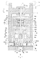
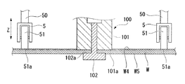
図1に示すように、本実施形態の摩擦攪拌接合装置1は、第一部材W1及び第二部材W2からなるワークWにおいて、第一部材W1と第二部材W2との接合箇所W3を摩擦攪拌接合により接合する装置である。摩擦攪拌接合装置1は、ワークWが配置されるワーク配置部2と、ワーク配置部2に配置されるワークWの表面W4側となる上方に設けられた本体部3と、該本体部3に設けられて、工具であるボビンツール100を保持する工具保持部4と、ワークWの表面W4上で工具保持部4を支持する支持体5と、支持体5に、ワーク配置部2に配置されるワークWに向かって、予め設定された荷重を与える荷重付与手段6とを備える。
Hereinafter, embodiments according to the present invention will be described with reference to the drawings.
As shown in FIG. 1, the friction stir welding apparatus 1 according to the present embodiment friction stirs a joint W3 between the first member W1 and the second member W2 in a workpiece W composed of a first member W1 and a second member W2. It is an apparatus for joining by joining. The friction stir welding apparatus 1 includes a
ここで、図2に示すように、ボビンツール100は、ワークWの表面W4側に配置され、該表面W4を押圧する第一ショルダ面101aを具備する第一ショルダ部101と、ワークWの裏面W5側に配置され、該裏面W5を押圧する第二ショルダ面102aを具備する第二ショルダ部102と、第一ショルダ部101の第一ショルダ面101aから突出して第二ショルダ部102が連結された軸部103とを有する。第一ショルダ部101には、第一ショルダ面101aに開口する貫通孔が形成されており、該貫通孔に軸部103が挿通されている。このため、軸部103を貫通孔に沿って進退させることによって第一ショルダ面101aに対して第二ショルダ面102aを近接離間させることが可能となっている。
Here, as shown in FIG. 2, the
図1に示すように、工具保持部4は、第一ショルダ部101が端面に取り付けられる略筒状の第一ショルダ取付体40と、先端に軸部103が取り付けられる第二ショルダ取付軸41と、略筒状で、第一ショルダ取付体40及び第二ショルダ取付軸41を支持する支持筒42とを有する。ここで、第一ショルダ取付体40、第二ショルダ取付軸41及び支持筒42は、同軸上に、中心軸Cをワーク対向方向となる上下方向Zに沿うように設けられている。
As shown in FIG. 1, the
第一ショルダ取付体40は、略筒状に形成されている。そして、第二ショルダ取付軸41は、第一ショルダ取付体40に挿通され、基端は第一ショルダ取付体40から突出している。第二ショルダ取付軸41には、第一ショルダ取付体40に挿通された部分において、軸方向に沿うようにしてキー41aが形成されているとともに、第一ショルダ取付体40から突出した部分には平板状のピストン41bが径方向に張り出している。一方、第一ショルダ取付体40には、第二ショルダ取付軸41のキー41aが噛合する中心軸Cに沿うキー溝40aが形成されていて、これにより第二ショルダ取付軸41は、第一ショルダ取付体40に対して中心軸C回りに回転不能であるとともに、中心軸Cに沿って進退可能となっている。また、第一ショルダ取付体40は、基端に径方向に張り出すフランジ40bを有する。
The first
支持筒42は、下方に開口して第一ショルダ取付体40を中心軸C回りに回転可能に収容する取付体収容部42aと、第二ショルダ取付軸41を中心軸Cに沿って進退させるシリンダ部42bと、本体部3に支持される被支持部42cとを有する。取付体収容部42aには、第一ショルダ取付体40のフランジ40bを収容するとともに、中心軸C回りに回転可能に支持する軸受部42dを有する。また、取付体収容部42aの内周面には、第一ショルダ取付体40を中心軸C回りに回転駆動するモータ43が内蔵されている。このため、キー41a及びキー溝40aが噛合ことによって一体となっている第一ショルダ取付体40と第二ショルダ取付軸41とは、モータ43の駆動により中心軸C回りに回転可能となっている。
The
シリンダ部42bは、ピストン41bを支持する略筒状のピストン支持部42eと、ピストン支持部42eの先端側及び基端側の開口に設けられ、第二ショルダ取付軸41を支持する先端側支持部42f及び基端側支持部42gとを有する。ピストン41bの外周面には軸受42hが設けられており、当該軸受42hにより、ピストン41bは、ピストン支持部42eに対して、中心軸Cに沿って進退可能かつ中心軸C回りに回転可能に支持されている。また、先端側支持部42f及び基端側支持部42gにも軸受42i、42jが設けられており、当該軸受42i、42jにより、第二ショルダ取付軸41は、ピストン支持部42eに対して、中心軸Cに沿って進退可能かつ中心軸C回りに回転可能に支持されている。
The
そして、ピストン41bと、先端側支持部42f及び基端側支持部42gとの間には、作動油が供給される第一油圧室42m及び第二油圧室42nが形成されている。また、シリンダ部42bには、本体部3にも貫通して外部まで接続されるとともに、それぞれ第一油圧室42mまたは第二油圧室42nまで連通する作動油供給管路42p、42qが形成されている。このため、外部に設けられた図示しない油圧制御装置から、作動油供給管路42p、42qを経由して第一油圧室42mまたは第二油圧室42nに選択的に油圧を入力することにより、第二ショルダ取付軸41を先端側または基端側へと中心軸Cに沿ってスライドさせることができる。これによりワーク配置部2に配置されたワークWの裏面W5に対して、中心軸Cに沿うワーク対向方向に力を与えて第二ショルダ部102の第二ショルダ面102aによって加圧を行うことが可能であり、すなわち図示しない油圧制御装置、シリンダ部42b及びピストン41bにより加圧手段44が構成されている。また、被支持部42cは、中心軸C上でシリンダ部42bから突出する軸状に形成されている。
A first
本体部3は、加工機主軸1aに取り付けられている。本体部3は、略筒状に形成され、ワーク配置部2に配置されるワークWの表面W4側となる下方に向けて開口し工具保持部4が収容された収容部30と、収容部30に収容された工具保持部4をワークWに対して近接離間するワーク対向方向となる上下方向Zに進退可能に支持する本体支持部31とを有する。本体支持部31は、軸受31a、31bを有し、被支持部42cは当該軸受31a、31bにより中心軸Cに沿って進退可能に支持されている。
The main body 3 is attached to the
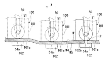
図1及び図3に示すように、支持体5は、工具保持部4の取付体収容部42aの下端面から突出する支持部材50と、支持部材50に回転可能に支持されてワークWの表面W4に当接するローラ51と、支持部材50から径方向に張り出すように設けられた張出部材52とを有する。支持体5は、工具保持部4に保持されたボビンツール100を走査する走査方向(図1において紙面奥行方向)に直交する方向Yに当該ボビンツール100を挟むようにして両側に対をなして配置されている。そして、ローラ51は、走査方向に直交する方向Yに沿うように配された回転軸回りに回転可能であり、すなわち走査方向へのボビンツール100の走査に伴ってワークWの表面W4上を走査方向に転動可能である。
As shown in FIGS. 1 and 3, the
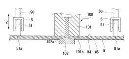
ここで、図3に示すように、支持体5においてワーク配置部2に配置されたワークWの表面W4に当接する当接部、すなわちローラ51の下端51aの上下方向Zの位置は、工具保持部4に保持されたボビンツール100の第一ショルダ部101の第一ショルダ面101aと略等しい位置に設定されている。このため、平面状に形成されたワークWの表面W4上においては、ローラ51の下端51aが表面W4に当接した状態で、第一ショルダ部101の第一ショルダ面101aも表面W4に当接した状態となっている。
Here, as shown in FIG. 3, the position in the vertical direction Z of the
また、図1に示すように、荷重付与手段6は、支持体5が接続されて下向きとなる自重及び保持するボビンツール100の重量分の力P1を作用させる工具保持部4と、張出部材52と本体部3の下端面との間に設けられ、中心軸Cに沿う方向に補助力P2を作用させる補助力付与部60とを有する。補助力付与部60は、工具保持部4によって作用される力P1よりも小さい所定の大きさの上向きの補助力P2を与えるものである。例えば、工具保持部4及びボビンツール100を合わせた重量による力P1が下向きに5.0kNであるのに対して、補助力P2としては上向きに4.5kNの大きさで作用させて、結果として荷重付与手段6としては、下向きの荷重Pで0.5kN作用させる。補助力付与部60は、具体的にはエアシリンダであり、上記の例では、予め4.5kN相当の空気圧の入力を行い、加工中においてワークWの表面W4の変位等にともなって反力を受けるなどしても特に入力された空気圧の制御は行わない。
As shown in FIG. 1, the
次に、この実施形態の作用について説明する。
図1に示すように、摩擦攪拌接合を行う場合には、第一ショルダ部101の第一ショルダ面101aと、第二ショルダ部102の第二ショルダ面102aとの間にワークWを配置する。また、ワークWの表面W4上に支持体5のローラ51を配置させる。この状態で、補助力付与部60で所定の大きさで上向きの補助力P2が作用していることにより、支持体5には荷重Pが作用し、当該荷重Pが支持体5からワークWに作用することによって、支持体5にはワークWから荷重P相当の反力が作用している。そして、モータ43を駆動させて工具保持部4全体を回転させるとともに、加圧手段44によって第二ショルダ部102に上向きの加圧力を作用させる。これにより、ワークWは、第二ショルダ面102aから裏面W5に加圧力を受けるとともに、第一ショルダ面101aから表面W4にも上記加圧力相当の加圧力を同様に受けることになる。このため、第一ショルダ面101a及び第二ショルダ面102aと、ワークWの表面W4及び裏面W5との間には摩擦熱が生じて軟化し、軟化部を軸部103で攪拌することで、摩擦攪拌接合が行われる。
Next, the operation of this embodiment will be described.
As shown in FIG. 1, when performing friction stir welding, the workpiece | work W is arrange | positioned between the
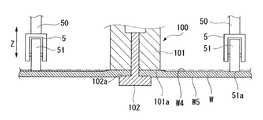
ここで、支持体5が、工具保持部4に保持されたボビンツール100に対してボビンツール100の走査方向に直交する方向Yに配置されていることで、ボビンツール100によるワークWの摩擦攪拌に支障がないようにして、ワークWの表面W4上で支持体5によって工具保持部4を支持することができる。そして、支持体5には、上記のとおり、荷重付与手段6によって荷重Pが作用することにより、ワークWの表面W4からも荷重P相当の反力を受けることとなる。このため、図4に示すように、ワークWの表面W4が、ワークW自体の変形、厚みの変化、ワーク配置部2におけるワークWの配置誤差等により、走査方向Xに沿って変位していたとしても、支持体5はワークWの表面W4に沿うように追従することとなる。
Here, the
また、ボビンツール100の第一ショルダ面101aは、支持体5のローラ51の下端51aとワーク対向方向となる上下方向Zの位置が等しくなるようにして一定の相対位置関係に設定されている。このため、工具保持部4に保持されたボビンツール100の第一ショルダ面101aは、工具保持部4とともに、ワークWの表面W4に沿うようにしてワーク対向方向に変位し、ワークWの表面W4との相対位置関係を一定に保つことができる。従って、ボビンツール100の第一ショルダ面101aからワークWの表面W4に作用する加圧力を所望の力で正確に維持することがきる。
Further, the
ここで、本実施形態の摩擦攪拌接合装置1では、少なくとも上記のように工具保持部4がワーク対向方向である上下方向Zに向かって進退可能であり、当該工具保持部4をワークWの表面W4上で支持体5によって支持することによって加圧力を正確に維持することを可能とするものであり、簡易な構成で、ワークWの表面W4に生じる誤差の影響を受けることなく、ボビンツール100によって正確に加圧して摩擦攪拌接合を行うことができる。この際、走査方向に対して支持体5とボビンツール100が同じ位置にあることで、ボビンツール100の位置におけるワークWの上下方向の微小な誤差をより正確に検知することができる。
Here, in the friction stir welding apparatus 1 of the present embodiment, at least the
また、上記のとおり、支持体5においてワークWの表面W4と当接する当接部となるローラ51の下端51aに対して、工具保持部4に保持されたボビンツール100の第一ショルダ部101の第一ショルダ面101aが上下方向Zに略等しい位置に設定されている。このため、図5に示すように、ワークWの表面W4において、第一ショルダ面101aで加圧される部位が他の部位に比較して、凹凸してしまうことがない。このため、摩擦攪拌接合後の仕上がりを良好なものとすることができる。また、上記のとおり、荷重付与手段6では、工具保持部4及びボビンツール100の重量による力P1から補助力P2を減じた荷重Pを与えることで、ワークWに余計な負荷を与えず、かつ、支持体5がワークWの表面W4を沿うような適切な反力を発生させることができる。
In addition, as described above, the
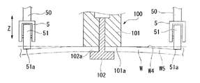
なお、上記においては、支持体5においてワークWの表面W4と当接する当接部となるローラ51の下端51aに対して、工具保持部4に保持されたボビンツール100の第一ショルダ部101の第一ショルダ面101aが上下方向Zに略等しい位置に設定されているものとしたが、これに限るものではない。例えば、図6に示すように、曲面状のワークWについて摩擦攪拌接合する場合には、曲面状の表面W4に沿う面において、同一面内となるように設けられていることで、表面W4における凹凸を防止して、同様に摩擦攪拌接合後の仕上がりを良好なものとすることができる。
In the above description, the
また、当接部となるローラ51の下端51aに対して、工具保持部4に保持されたボビンツール100の第一ショルダ部101の第一ショルダ面101aは、上下方向Zに異なる位置としても相対位置が所定の関係となるようにして設けられていれば良い。
例えば、図7に示すように、ローラ51の下端51aに対して、第一ショルダ面101aがワークWに近い位置に位置していたとしても良い。この場合には、第一ショルダ面101aがローラ51の下端51aよりもワークWに近接した距離分だけ、接合部に凹部が形成されることとなる。例えば、接合部において所定の深さで凹部を形成する必要がある場合などには、このような位置関係としても良い。また、図8に示すように、ローラ51の下端51aに対して、第一ショルダ面101aがワークWに遠い位置に位置していたとしても良い。この場合には、第一ショルダ面101aがローラ51の下端51aよりもワークWに離間した距離分だけ、接合部に凸部が形成されることとなる。例えば、接合部において所定の高さで凸部を形成する必要がある場合などには、このような位置関係としても良い。
Further, the
For example, as shown in FIG. 7, the
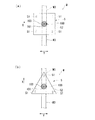
また、上記においては、支持体5は、工具保持部4に保持されたボビンツール100を走査する走査方向に直交する方向に当該ボビンツール100を挟むようにして両側に対をなして配置されているものとしたが、これに限るものではない。例えば、図9(a)に示すように平面視して4つの支持体5を備えるものとしたり、あるいは、図9(b)に示すように平面視して3つの支持体5を備えるものとしても良い。
Further, in the above, the
図9(a)に示す4つの支持体5を配置する場合、工具保持部4に保持されたボビンツール100の走査方向Xに直交する方向Y両側に、走査方向Xに沿うようにそれぞれ2つずつ配列することで、ボビンツール100によるワークWの摩擦攪拌に支障がないようにして、ワークWの表面W4上で支持体5によって工具保持部4を支持することができる。また、この場合には、ボビンツール100の走査方向Xを90度変更しても同様にボビンツール100による摩擦攪拌に支障がない。
When arranging the four
また、図9(b)に示す3つの支持体5を配置する場合、工具保持部4に保持されたボビンツール100の走査方向Xに直交する方向Y両側に2つを配置し、残りの1つを走査方向X前方側に配置するようにしても、走査方向X前方側の支持体5は摩擦攪拌による接合前のワークWの表面W4上を走行することになるため、同様にボビンツール100による摩擦攪拌に支障がない。
When arranging the three
また、上記実施形態では、工具保持部4をワーク配置部2に配置されたワークWの上方に配置し、工具保持部4をワーク対向方向である上下方向Zに進退可能としたが、これに限るものではない。例えば、ワークWを、表面W4が鉛直面をなすように配置して、工具保持部4をワーク対向方向となる水平方向に進退可能としても良い。この場合には、支持体5には、工具保持部4及び工具保持部4で保持されたボビンツール100の重量が力として作用しない。このため、図1に示す構造で、支持体5に荷重を付与するためには、荷重付与手段6で発生する荷重として補助力付与部60で発生させる力そのものを利用し、ワークWに向かって対応する荷重、例えば上記実施形態における例では0.5kNの力を発生させるように空気圧を入力すればよい。また、上記実施形態では、加圧手段44を備え、第一ショルダ部101に対して第二ショルダ部102が近接離間可能なものとしたが、これに限るものでなく、第一ショルダ部101に対して第二ショルダ部102が相対位置不変に固定されていて、加圧手段44を備えない構成としても良い。
Moreover, in the said embodiment, although the tool holding |
以上、本発明の実施形態について図面を参照して詳述したが、具体的な構成はこの実施形態に限られるものではなく、本発明の要旨を逸脱しない範囲の設計変更等も含まれる。 As mentioned above, although embodiment of this invention was explained in full detail with reference to drawings, the concrete structure is not restricted to this embodiment, The design change etc. of the range which does not deviate from the summary of this invention are included.
1 摩擦攪拌接合装置
2 ワーク配置部
3 本体部
4 工具保持部
5 支持体
51a 下端(当接部)
6 荷重付与手段
44 加圧手段
60 補助力付与部
100 ボビンツール(工具)
101 第一ショルダ部
101a 第一ショルダ面
102 第二ショルダ部
102a 第二ショルダ面
103 軸部
W ワーク
W4 表面
W5 裏面
X 走査方向
Y 走査方向に直交する方向
Z 上下方向(ワーク対向方向)
DESCRIPTION OF SYMBOLS 1 Friction
6 Load applying means 44 Pressurizing means 60 Auxiliary
101
Claims (11)
前記ワークが配置されるワーク配置部と、
該ワーク配置部に配置される前記ワークの前記表面側に設けられた本体部と、
該本体部に、前記ワーク配置部に配置される前記ワークに対して近接離間する方向であるワーク対向方向に進退可能に設けられ、前記工具を保持する工具保持部と、
該工具保持部に取り付けられた前記工具の前記第一ショルダ面と前記ワーク対向方向に所定の相対位置関係となるようにして設けられ、前記ワーク配置部に配置された前記ワークの前記表面上で、前記工具保持部を支持する支持体とを備えることを特徴とする摩擦攪拌接合装置。 A friction stir welding apparatus that performs friction stir welding on the workpiece using a tool having a first shoulder surface that contacts the surface of the workpiece and a second shoulder surface that contacts the back surface of the workpiece,
A work placement section on which the work is placed;
A main body provided on the surface side of the workpiece disposed in the workpiece placement portion;
A tool holding portion that is provided in the main body portion so as to be able to advance and retreat in a workpiece facing direction that is a direction of approaching and separating from the workpiece arranged in the workpiece arrangement portion;
On the surface of the workpiece disposed in the workpiece placement portion, provided in a predetermined relative positional relationship in the workpiece facing direction with the first shoulder surface of the tool attached to the tool holding portion. A friction stir welding apparatus comprising: a support body that supports the tool holding portion.
前記支持体に、前記ワーク配置部に配置される前記ワークに向かって、予め設定された荷重を与える荷重付与手段を備えることを特徴とする摩擦攪拌接合装置。 In the friction stir welding apparatus according to claim 1,
A friction stir welding apparatus, comprising: a load applying unit that applies a preset load toward the work placed on the work placing portion on the support.
前記本体部が、前記ワーク配置部に配置される前記ワークの上方に配置され、前記ワーク対向方向として上下方向に前記工具保持部を進退可能に支持しており、
前記荷重付与手段は、前記本体部に取り付けられ、前記工具保持部に対して、該工具保持部と該工具保持部に取り付けられた前記工具の重量よりも小さい所定の大きさの上向きの補助力を与える補助力付与部を有し、前記荷重として、該工具保持部と該工具保持部に取り付けられた前記工具の重量から前記補助力を減じた荷重を与えることを特徴とする摩擦攪拌接合装置。 In the friction stir welding apparatus according to claim 2,
The main body portion is disposed above the workpiece arranged in the workpiece arrangement portion, and supports the tool holding portion in a vertical direction as the workpiece facing direction so as to advance and retreat.
The load applying means is attached to the main body, and has an upward auxiliary force with a predetermined size smaller than the weight of the tool holding portion and the tool attached to the tool holding portion with respect to the tool holding portion. A friction stir welding apparatus characterized in that a load obtained by subtracting the auxiliary force from the weight of the tool holding part and the tool attached to the tool holding part is given as the load. .
前記支持体は、前記工具保持部に保持された前記工具に対して、該工具の走査方向に直交する方向に配置されていることを特徴とする摩擦攪拌接合装置。 In the friction stir welding apparatus according to any one of claims 1 to 3,
The friction stir welding apparatus according to claim 1, wherein the support is arranged in a direction orthogonal to a scanning direction of the tool held by the tool holding unit.
前記支持体は、前記ワークの前記表面に当接する当接部が、前記工具保持部に保持された前記工具の前記第一ショルダ面と、前記ワークの前記表面に沿う同一面内となるように設けられていることを特徴とする摩擦攪拌接合装置。 In the friction stir welding apparatus according to any one of claims 1 to 4,
The support is configured such that a contact portion that contacts the surface of the workpiece is in the same plane along the first shoulder surface of the tool held by the tool holding portion and the surface of the workpiece. A friction stir welding apparatus characterized by being provided.
前記工具が、前記第一ショルダ面を具備する第一ショルダ部と、前記第一ショルダ面から進退可能に突出する軸部と、該軸部の先端に取り付けられ前記第二ショルダ面を具備する第二ショルダ部とを有し、
前記工具保持部は、前記軸部に前記ワーク対向方向に力を与えて、前記第二ショルダ面によって前記ワークの前記裏面を加圧させる加圧手段を有することを特徴とする摩擦攪拌接合装置。 In the friction stir welding apparatus according to any one of claims 1 to 5,
The tool includes a first shoulder portion having the first shoulder surface, a shaft portion projecting forward and backward from the first shoulder surface, and a second shoulder surface attached to the tip of the shaft portion. Two shoulder parts,
The tool holding unit includes a pressurizing unit that applies a force to the shaft portion in the workpiece facing direction to pressurize the back surface of the workpiece by the second shoulder surface.
ワーク配置部に配置された前記ワークの表面に対して、工具を保持する工具保持部を、前記ワークに対して近接離間する方向であるワーク対向方向に進退可能としつつ、前記ワーク対向方向に前記工具の前記第一ショルダ面と所定の相対位置関係となるようにした支持体によって前記ワークの前記表面上で支持された状態として、前記工具によって摩擦攪拌接合を行うことを特徴とする摩擦攪拌接合方法。 With respect to the surface of the workpiece arranged in the workpiece arrangement unit, the tool holding unit that holds the tool can be advanced and retracted in the workpiece facing direction, which is a direction approaching and separating from the workpiece, and the workpiece facing direction in the workpiece facing direction. Friction stir welding is performed by the tool in a state of being supported on the surface of the workpiece by a support body having a predetermined relative positional relationship with the first shoulder surface of the tool. Method.
前記支持体から前記ワークに向かって、予め設定された荷重を与えた状態で前記工具によって摩擦攪拌接合を行うことを特徴とする摩擦攪拌接合方法。 A friction stir welding method, wherein the tool is subjected to friction stir welding with a preset load applied from the support to the workpiece.
前記ワークの上方に前記工具保持部を配置して前記ワーク対向方向として上下方向に前記工具を進退可能に支持した状態で、前記工具保持部と該工具保持部に取り付けられた前記工具の重量よりも小さい所定の大きさの上向きの補助力を与えることで、荷重として、該工具保持部と該工具保持部に取り付けられた前記工具の重量から、前記補助力を減じた荷重を前記支持体から前記ワークに向かって与えることを特徴とする摩擦攪拌接合方法。 From the weight of the tool holding part and the tool attached to the tool holding part in a state where the tool holding part is arranged above the work and the tool is supported so as to be able to advance and retreat in the vertical direction as the work facing direction. By applying an upward auxiliary force of a predetermined size, the load obtained by subtracting the auxiliary force from the weight of the tool holding portion and the tool attached to the tool holding portion from the support as a load. A friction stir welding method characterized by being applied toward the workpiece.
前記支持体を、前記工具保持部に保持された前記工具に対して、該工具の走査方向に直交する方向に配置することを特徴とする摩擦攪拌接合方法。 The friction stir welding method, wherein the support is disposed in a direction orthogonal to a scanning direction of the tool with respect to the tool held by the tool holding unit.
前記支持体を、前記ワークの前記表面に当接する当接部が、前記工具保持部に保持された前記工具の前記第一ショルダ面と、前記ワークの前記表面に沿う同一面内となるようにして前記ワークの表面上に支持された状態とすることを特徴とする摩擦攪拌接合方法。 The abutting portion that abuts the support on the surface of the workpiece is in the same plane along the surface of the workpiece as the first shoulder surface of the tool held by the tool holding portion. The friction stir welding method is characterized in that it is supported on the surface of the workpiece.
Priority Applications (5)
| Application Number | Priority Date | Filing Date | Title |
|---|---|---|---|
| JP2011033503A JP5374528B2 (en) | 2011-02-18 | 2011-02-18 | Friction stir welding apparatus and friction stir welding method |
| US13/812,642 US9776276B2 (en) | 2011-02-18 | 2011-05-27 | Friction stir welding device |
| PCT/JP2011/062213 WO2012111181A1 (en) | 2011-02-18 | 2011-05-27 | Friction stir welding device |
| CN201180037181.XA CN103068514B (en) | 2011-02-18 | 2011-05-27 | Friction-stir engagement device |
| EP11858672.6A EP2676762B1 (en) | 2011-02-18 | 2011-05-27 | Friction stir welding device |
Applications Claiming Priority (1)
| Application Number | Priority Date | Filing Date | Title |
|---|---|---|---|
| JP2011033503A JP5374528B2 (en) | 2011-02-18 | 2011-02-18 | Friction stir welding apparatus and friction stir welding method |
Publications (2)
| Publication Number | Publication Date |
|---|---|
| JP2012170966A JP2012170966A (en) | 2012-09-10 |
| JP5374528B2 true JP5374528B2 (en) | 2013-12-25 |
Family
ID=46672137
Family Applications (1)
| Application Number | Title | Priority Date | Filing Date |
|---|---|---|---|
| JP2011033503A Active JP5374528B2 (en) | 2011-02-18 | 2011-02-18 | Friction stir welding apparatus and friction stir welding method |
Country Status (5)
| Country | Link |
|---|---|
| US (1) | US9776276B2 (en) |
| EP (1) | EP2676762B1 (en) |
| JP (1) | JP5374528B2 (en) |
| CN (1) | CN103068514B (en) |
| WO (1) | WO2012111181A1 (en) |
Families Citing this family (12)
| Publication number | Priority date | Publication date | Assignee | Title |
|---|---|---|---|---|
| AT509066B1 (en) * | 2010-08-11 | 2011-06-15 | Stirzone Og | DEVICE FOR REINFORCING WELDING |
| JP5536007B2 (en) * | 2011-10-19 | 2014-07-02 | 三菱重工業株式会社 | Friction stir welding apparatus and friction stir welding method |
| JP5863996B2 (en) | 2012-12-19 | 2016-02-17 | 三菱重工業株式会社 | Manufacturing method of bonding material and bonding jig |
| JP6084887B2 (en) * | 2013-04-16 | 2017-02-22 | 川崎重工業株式会社 | Friction stir welding apparatus and friction stir welding method |
| JP6226184B2 (en) * | 2013-11-07 | 2017-11-08 | 三菱重工業株式会社 | Friction stir welding method |
| DE102014101627A1 (en) * | 2014-02-10 | 2015-08-13 | Ms Spaichingen Gmbh | Rack for a machine |
| CN106163722B (en) * | 2014-04-16 | 2018-08-31 | 本田技研工业株式会社 | Friction-stir engagement device |
| ES2651500T3 (en) * | 2015-03-18 | 2018-01-26 | Helmholtz-Zentrum Geesthacht Zentrum für Material- und Küstenforschung GmbH | Apparatus for welding by friction-stirring with a projection comprising first and second through holes |
| US10953487B2 (en) * | 2015-09-29 | 2021-03-23 | Toshiba Mitsubishi-Electric Industrial Systems Corporation | Ultrasonic vibration bonding apparatus |
| KR101833294B1 (en) * | 2016-09-19 | 2018-03-02 | 주식회사 현성오토텍 | Rotation joining members for friction stir welding |
| CN114589393A (en) * | 2020-12-07 | 2022-06-07 | 财团法人金属工业研究发展中心 | Friction stir welding pressing jig system |
| DE102021126767A1 (en) | 2021-10-15 | 2023-04-20 | Universität Kassel, Körperschaft des öffentlichen Rechts | friction stir welding device |
Family Cites Families (18)
| Publication number | Priority date | Publication date | Assignee | Title |
|---|---|---|---|---|
| JPS594230B2 (en) | 1974-10-03 | 1984-01-28 | 三菱重工業株式会社 | Kumitateyousetsouchi |
| JPH10305372A (en) * | 1997-05-07 | 1998-11-17 | Amada Co Ltd | Welding device |
| WO2000002704A1 (en) * | 1998-07-09 | 2000-01-20 | Mts Systems Corporation | Control system for friction stir welding |
| JP2001287054A (en) * | 2000-04-07 | 2001-10-16 | Hitachi Ltd | Friction-stir-welding method |
| US6302315B1 (en) * | 2000-05-01 | 2001-10-16 | General Tool Company | Friction stir welding machine and method |
| JP2003062679A (en) * | 2001-08-29 | 2003-03-05 | Nippon Light Metal Co Ltd | Friction stirring type jointing tool |
| JP4335513B2 (en) * | 2002-10-08 | 2009-09-30 | 三菱重工業株式会社 | Friction stir welding apparatus and friction stir welding method |
| JP3735342B2 (en) * | 2002-12-13 | 2006-01-18 | 三菱重工業株式会社 | Equipment for manufacturing bonded structures by friction stir |
| JP3740125B2 (en) * | 2003-01-16 | 2006-02-01 | 三菱重工業株式会社 | Friction stir welding apparatus and joining method thereof |
| JP3836090B2 (en) * | 2003-06-20 | 2006-10-18 | 三菱重工業株式会社 | Method and apparatus for manufacturing rocket tank cylinder |
| JP4468125B2 (en) * | 2004-09-27 | 2010-05-26 | 三菱重工業株式会社 | Friction stir welding method and apparatus |
| US8397974B2 (en) * | 2005-09-26 | 2013-03-19 | Aeroprobe Corporation | Self-reacting friction stir welding tool with the ability to add filler material |
| JP4790584B2 (en) | 2006-12-14 | 2011-10-12 | 日本車輌製造株式会社 | Friction stir welding apparatus and friction stir welding method |
| CN101622093B (en) * | 2007-03-30 | 2013-03-13 | 川崎重工业株式会社 | Suction pad, friction stir welding device, and friction stir welding system |
| US8079276B2 (en) * | 2008-04-15 | 2011-12-20 | Spirit Aerosystems, Inc. | Dynamic calibration assembly for a friction stir welding machine |
| US8052028B2 (en) * | 2008-06-16 | 2011-11-08 | GM Global Technology Operations LLC | Device for use with a friction stir spot welding (FSSW) apparatus |
| JP5535502B2 (en) * | 2009-03-16 | 2014-07-02 | 川崎重工業株式会社 | Friction stir welding apparatus and method |
| CN101947691B (en) * | 2010-09-29 | 2012-05-30 | 哈尔滨工业大学 | Self-supporting friction stir welding method with unequal diameters of upper and lower shaft shoulders and stirring head thereof |
-
2011
- 2011-02-18 JP JP2011033503A patent/JP5374528B2/en active Active
- 2011-05-27 CN CN201180037181.XA patent/CN103068514B/en active Active
- 2011-05-27 WO PCT/JP2011/062213 patent/WO2012111181A1/en active Application Filing
- 2011-05-27 EP EP11858672.6A patent/EP2676762B1/en active Active
- 2011-05-27 US US13/812,642 patent/US9776276B2/en active Active
Also Published As
| Publication number | Publication date |
|---|---|
| US9776276B2 (en) | 2017-10-03 |
| JP2012170966A (en) | 2012-09-10 |
| US20130119115A1 (en) | 2013-05-16 |
| EP2676762A4 (en) | 2016-12-28 |
| WO2012111181A1 (en) | 2012-08-23 |
| CN103068514B (en) | 2016-02-17 |
| CN103068514A (en) | 2013-04-24 |
| EP2676762B1 (en) | 2019-03-13 |
| EP2676762A1 (en) | 2013-12-25 |
Similar Documents
| Publication | Publication Date | Title |
|---|---|---|
| JP5374528B2 (en) | Friction stir welding apparatus and friction stir welding method | |
| JP4751477B1 (en) | Work clamping device in machine tools | |
| JP4332157B2 (en) | Friction stir welding equipment | |
| US9481049B2 (en) | Combined machining method and combined machining device | |
| JP5725868B2 (en) | End processing equipment | |
| JP5984561B2 (en) | Friction stir welding equipment | |
| JP5856212B2 (en) | Jig and processing system for supporting a workpiece rotatably with respect to a tool of a machine tool | |
| JP2013184261A (en) | Tool for machining workpiece, device for automatically machining workpiece, method for machining workpiece, program for machining workpiece, and recording medium | |
| JP5022502B2 (en) | Friction stir welding equipment | |
| KR101799218B1 (en) | Friction stir welding method | |
| KR20140026662A (en) | Apparatus for welding and method having the same | |
| KR20100070438A (en) | Pushing jig and fixing device having the same | |
| KR20100061302A (en) | Friction welding apparatus with deburring device and deburring method by using the same | |
| JP4740289B2 (en) | Friction stir welding equipment | |
| JP2010142936A (en) | Cylinder head fixing device | |
| JP2008183651A (en) | Clamping device of stage change plate | |
| JP2003205374A (en) | Spot welding system and fixing device | |
| JP2009128196A (en) | Device for measuring working reference position of workpiece, and working-measuring system | |
| CN108290260B (en) | Workpiece holding device | |
| JP2004195586A (en) | Shaft machining method in machine tool, machining jig for performing this method and shaft machining support device | |
| JP2008302440A (en) | Workpiece mounting tool and machine tool | |
| JP5931459B2 (en) | Friction stir welding equipment | |
| CN214815988U (en) | Structure for assembling and positioning welding parts | |
| CN218426534U (en) | Automatic quick-change welding device of robot | |
| JP2012213827A (en) | Drilling machine |
Legal Events
| Date | Code | Title | Description |
|---|---|---|---|
| A521 | Request for written amendment filed |
Free format text: JAPANESE INTERMEDIATE CODE: A523 Effective date: 20120611 |
|
| A621 | Written request for application examination |
Free format text: JAPANESE INTERMEDIATE CODE: A621 Effective date: 20120611 |
|
| A521 | Request for written amendment filed |
Free format text: JAPANESE INTERMEDIATE CODE: A821 Effective date: 20120612 |
|
| TRDD | Decision of grant or rejection written | ||
| A01 | Written decision to grant a patent or to grant a registration (utility model) |
Free format text: JAPANESE INTERMEDIATE CODE: A01 Effective date: 20130827 |
|
| A61 | First payment of annual fees (during grant procedure) |
Free format text: JAPANESE INTERMEDIATE CODE: A61 Effective date: 20130920 |
|
| R151 | Written notification of patent or utility model registration |
Ref document number: 5374528 Country of ref document: JP Free format text: JAPANESE INTERMEDIATE CODE: R151 |
|
| R250 | Receipt of annual fees |
Free format text: JAPANESE INTERMEDIATE CODE: R250 |
|
| S111 | Request for change of ownership or part of ownership |
Free format text: JAPANESE INTERMEDIATE CODE: R313111 |
|
| R350 | Written notification of registration of transfer |
Free format text: JAPANESE INTERMEDIATE CODE: R350 |
|
| S533 | Written request for registration of change of name |
Free format text: JAPANESE INTERMEDIATE CODE: R313533 |
|
| R350 | Written notification of registration of transfer |
Free format text: JAPANESE INTERMEDIATE CODE: R350 |
|
| S111 | Request for change of ownership or part of ownership |
Free format text: JAPANESE INTERMEDIATE CODE: R313111 |
|
| R350 | Written notification of registration of transfer |
Free format text: JAPANESE INTERMEDIATE CODE: R350 |