EP2907720B1 - Sliding door module/swing door module for a rail vehicle with elastic supporting structure - Google Patents
Sliding door module/swing door module for a rail vehicle with elastic supporting structure Download PDFInfo
- Publication number
- EP2907720B1 EP2907720B1 EP14185559.3A EP14185559A EP2907720B1 EP 2907720 B1 EP2907720 B1 EP 2907720B1 EP 14185559 A EP14185559 A EP 14185559A EP 2907720 B1 EP2907720 B1 EP 2907720B1
- Authority
- EP
- European Patent Office
- Prior art keywords
- sliding door
- door module
- carrier
- guiding
- module
- Prior art date
- Legal status (The legal status is an assumption and is not a legal conclusion. Google has not performed a legal analysis and makes no representation as to the accuracy of the status listed.)
- Active
Links
- 230000003068 static effect Effects 0.000 claims description 12
- 238000005452 bending Methods 0.000 claims description 4
- 239000000835 fiber Substances 0.000 claims description 4
- 230000007935 neutral effect Effects 0.000 claims description 4
- 239000011796 hollow space material Substances 0.000 claims 1
- 238000005096 rolling process Methods 0.000 description 45
- 238000003860 storage Methods 0.000 description 7
- 238000010276 construction Methods 0.000 description 5
- 230000000694 effects Effects 0.000 description 5
- 230000002349 favourable effect Effects 0.000 description 5
- 230000035939 shock Effects 0.000 description 3
- 230000009471 action Effects 0.000 description 2
- 230000008901 benefit Effects 0.000 description 2
- 230000005540 biological transmission Effects 0.000 description 2
- 239000000872 buffer Substances 0.000 description 2
- 230000008859 change Effects 0.000 description 2
- 238000013016 damping Methods 0.000 description 2
- 230000005484 gravity Effects 0.000 description 2
- 230000007246 mechanism Effects 0.000 description 2
- 230000010355 oscillation Effects 0.000 description 2
- 229910000760 Hardened steel Inorganic materials 0.000 description 1
- 240000001439 Opuntia Species 0.000 description 1
- 235000004727 Opuntia ficus indica Nutrition 0.000 description 1
- 238000005094 computer simulation Methods 0.000 description 1
- 230000001419 dependent effect Effects 0.000 description 1
- 238000009826 distribution Methods 0.000 description 1
- 230000005489 elastic deformation Effects 0.000 description 1
- 238000009434 installation Methods 0.000 description 1
- 238000004519 manufacturing process Methods 0.000 description 1
- 230000004048 modification Effects 0.000 description 1
- 238000012986 modification Methods 0.000 description 1
Images


Classifications
-
- B—PERFORMING OPERATIONS; TRANSPORTING
- B61—RAILWAYS
- B61D—BODY DETAILS OR KINDS OF RAILWAY VEHICLES
- B61D19/00—Door arrangements specially adapted for rail vehicles
- B61D19/003—Door arrangements specially adapted for rail vehicles characterised by the movements of the door
- B61D19/005—Door arrangements specially adapted for rail vehicles characterised by the movements of the door sliding
-
- B—PERFORMING OPERATIONS; TRANSPORTING
- B61—RAILWAYS
- B61D—BODY DETAILS OR KINDS OF RAILWAY VEHICLES
- B61D19/00—Door arrangements specially adapted for rail vehicles
-
- B—PERFORMING OPERATIONS; TRANSPORTING
- B61—RAILWAYS
- B61D—BODY DETAILS OR KINDS OF RAILWAY VEHICLES
- B61D19/00—Door arrangements specially adapted for rail vehicles
- B61D19/003—Door arrangements specially adapted for rail vehicles characterised by the movements of the door
- B61D19/008—Door arrangements specially adapted for rail vehicles characterised by the movements of the door both swinging and sliding
Definitions
- the invention relates to a sliding door module / sliding door module for a rail vehicle, comprising at least one door, a longitudinally oriented in the sliding direction of the door carrier, which is mounted in particular displaceable transversely to its longitudinal extent in the horizontal direction, and a linear guide with a rail and at least one carriage / guide carriage ,
- the profile rail is fastened on the support or comprises it in the form of a profile region.
- the at least one carriage / guide carriage is mounted on the rail, and the door is slidably mounted by means of at least one guide carriage / guide carriage.
- Such a sliding door module is for example from the DE 692 04 556 T2 , according to the EP 0 517 334 A known.
- Sliding door modules / sliding sliding door modules of the type mentioned are basically known.
- a door or two leaves are slidably mounted, which are first issued to open in the case of a sliding door module with the help of a release mechanism and then moved or only be moved in the case of a sliding door module.
- the doors are usually stored with the help of linear roller guides.
- These linear roller guides are mainly known from the construction of machine tools, in which the exact guidance of machine parts is essential. These are therefore designed as free of play and require a relatively rigid substructure to avoid distortion of the linear roller guides and ensure a long life.
- the constructions used in the prior art are also designed to be relatively rigid, so that shocks acting on the rail vehicle, virtually unmitigated transmitted to the sliding door module / sliding door module. This in turn reduces the life of the linear guide.
- the known solutions are relatively heavy and thus have a negative effect on the overall weight of the rail vehicle. Especially in urban traffic, in which the rail vehicles are accelerated and braked at short distances, such a support structure degrades the energy efficiency of the rail vehicle.
- An object of the invention is therefore to provide an improved sliding door module / sliding door module.
- the disadvantages described above should be avoided or their effects should be least mitigated.
- Millimeters per kilogram door weight is.
- the maximum static deflection is measured when the rail vehicle is stationary and occurs at a certain position of the carrier at a specific position of the door leaf or the door leaf.
- the strongest deflection of the carrier occurs in a double-leaf sliding door in the middle of the carrier at slightly (a crack) open doors and a single-leaf sliding door in the middle of the carrier with half open sliding door and can exactly, for example in a computer simulation or be determined in an attempt.
- the "clear door width” refers to the width of the passage when the sliding door is fully open and is measured between the door frame, the door frame and a door leaf or between the two door leaves, depending on how far the door leaf (s) are opened.
- the deflection is given based on the weight of the door leaf or the door leaf.
- the maximum static deflection of the carrier between the outermost points of contact of the door carrying the carriage guide carriage / guide carriage with the rail (ie on the total guide length) with the door open additionally or alternatively at least 0.0075 mm, but especially 0.015 mm, 0.030 mm or even 0.075 mm per kg of door leaf weight.
- the linear guide is a linear roller guide
- the maximum static deflection of the carrier can also be related to the contact points of the outermost rolling elements bearing the door leaf with the profile rail. Again, the absolute deflection can be obtained by multiplying the specified value by the total weight of the leaves.
- the presented sliding door module / sliding sliding door module has a comparatively high degree of deformation.
- the support of the sliding door module / sliding door module is so targeted "soft" designed so that it acts essentially as a leaf spring and thus mitigated the transmission of impacts acting on the rail vehicle bumps on the sliding door module / sliding door module becomes. Due to the fact that impacts no longer act on the linear guide, this has an increased service life.
- the reduced weight of the carrier not only improves the energy efficiency of the rail vehicle, but also shifts the resonant frequency of the sliding door module / sliding door module toward higher frequencies, which can not or only to a limited extent excite vibrations of appreciable amplitude.
- Linear roller guides offer good ease of movement with little or no clearance, but they are very susceptible to overloading, especially shocks due to the high surface pressures between rolling elements and rail. Due to the soft design of the carrier but such shocks are very well damped, whereby the advantage of the invention when using linear roller guideways particularly stands out.
- Linear roller guides can be designed, for example, with balls or rollers as rolling elements.
- the rolling elements form the link between the profile rail and guide carriage in a contact area.
- the rolling elements not currently in contact with the rail are directed via a return area (e.g., return duct) from the end of the contact area to the beginning thereof or vice versa.
- the rolling elements thus move in a closed path.
- this orbit is arranged essentially in one plane, the "orbital plane".
- an oval-shaped path may be provided, or there are successively provided a plurality of oval-shaped or circular tracks, which are arranged in the same plane and form a contact area in their entirety.
- multiple tracks may also be in different but parallel planes.
- the tracks can also cross each other.
- an orbit may leave the orbital plane in the reverse region to allow for intersection with another orbit.
- the rolling elements can also be arranged in a rolling element cage.
- the sliding door module / sliding sliding door module has a plurality of (for example two) separate, in particular in the sliding direction of the door leaf from each other spaced, only one door associated with guide carriage / guide carriage.
- said guide carriages / guide carriages are mounted on only one rail.
- a door leaf can also be assigned a plurality of guide carriages / guide carriages which are mounted on different profile rails. In this way, the torque caused by the weight of the door leaf due to the spaced guide carriages / guide slides are well transferred to the carrier, on the other hand, the linear guide is due to the relatively short guide length of the individual guide carriages / guide carriage but also less susceptible to tension.
- the guide lengths of the guide carriages / guide carriages are at most half as long as the total guide length, ie the distance between the outermost points of contact of the guide carriages / guide carriages carrying the door leaf with the profile rail.
- the storage of the guide carriages / guide carriage remains smooth even with relatively strong deflection of the carrier or the rail.
- the guide length and the total guide length can in turn be related to the outermost, the door leaf-bearing rolling elements.
- the guide carriages / guide carriages are articulated to one another with a cross member respectively hinged to the door leaf. In this way, a deflection of the carrier can be compensated even better, since the guide carriages / guide carriages a local orientation of the carrier respectively the guide rail can follow better and the risk of distortion of the linear guide is thus reduced.
- the carrier is mounted essentially at its end points in relation to its longitudinal extent. In this way, a comparatively good damping effect of impacts acting on the rail vehicle can be achieved. In addition, in this arrangement usually results in a favorable installation situation.
- the Bessel points are advantageous positions of the supports of a loaded beam and are about 22% of the length of the beam. However, their specific position depends on the design of the carrier and the components mounted thereon and on the weight distribution.
- one of the bearing points of the carrier is designed as a fixed bearing and the other bearing point or the other bearing points as a movable bearing is / are. In this way, for example, a temperature-induced change in length of the wearer or a change in the distance between the end points of the support in deflection of the same can be compensated.
- the carrier in cross section on both sides of the rail is higher than in the region of the rail.
- the carrier has in cross-section on its top and bottom laterally from the rail to an increase.
- the carrier may also have a substantially H-shaped or X-shaped or T-shaped cross-section.
- the carrier has a cavity in the region of the neutral bending fiber, that is, the neutral fiber is arranged in said cavity.
- the carrier has a relatively low weight with good stability.
- the guide system comprises two linear guides, wherein a first rail on the top of the carrier and a second rail are mounted on the underside of the carrier is particularly advantageous.
- a sliding door module / sliding door module accordingly comprises a first pivot sliding door fixed to the lower linear guide and a second pivot sliding door attached to the upper linear guide.
- the height of the guide system is particularly low in this arrangement.
- the carrier is constructed symmetrically with respect to its horizontal axis, since then no special mounting direction is observed.
- the profile rail has a substantially C-shaped or U-shaped cross-section and the guide carriage / guide carriage is mounted between the opposite end legs of the C-shaped or U-shaped cross section.
- Such a linear roller guide is hardly susceptible to tension, whereby this has a comparatively long life when used in the proposed sliding door module / sliding door module.
- the linear guide is particularly tolerant to deformations of the guide system and thus particularly well suited for use in rail vehicles.
- the linear guide is also very durable.
- a drive for the door leaf is dimensioned such that the deflection of the support when closing the door leaf is reduced.
- Deflection of the carrier hanging outward door is moved when closing against the door frame or other sliding door and erected upon further action of sufficiently strong drive. Due to the point of contact of the door leaf with the door frame or another door leaf and the driving force acting on it, a torque acts on it. As a result, however, the carrier is pushed in the middle of the top, so that the deflection is reduced. This tension not only reduces the deflection of the carrier but also alters the vibration behavior of the sliding door module / sliding sliding door module, that is to say displaces it in the direction of higher resonance frequencies.
- the vibration behavior of the sliding door module / sliding door module can be controlled via the drive for the door leaves.
- drive all types of rotary motors or linear motors in question, for example, electric, pneumatic and hydraulic drives.
- the support structure for a door can be moved, for example by means of a spindle or a cable along the carrier.
- the door leaf is rotatably mounted about an axis running in the longitudinal direction of the carrier.
- tolerances can be compensated, on the other hand, such a sliding door module / sliding door module can also be well installed in rail vehicles whose side walls are inclined.
- the rotation can be made possible, for example. that the door is fixed by means of a rotatably mounted bolt on the cross member. But it is also conceivable that the door is fixedly connected to the cross member, but this is rotatably mounted to the rail.
- Fig. 1 shows sliding door module / sliding door module 1 for a rail vehicle in a highly simplified representation.
- the sliding door module / sliding sliding door module 1 comprises two door leaves 2 and a longitudinal direction in the sliding direction of the door 2 longitudinally oriented support 3, which is mounted in the case of a sliding door module transversely to its longitudinal extent displaceable in the horizontal direction or fixed in the case of a sliding door module.
- the sliding door module / sliding door module 1 comprises a linear guide, which is embodied in this example concretely as a linear roller guide.
- the linear roller guide comprises a profiled rail and two guide carriages 4, wherein the profiled rail is fastened on the support 3 or is enclosed by it in the form of a profile area.
- the profile rail is not explicitly shown for the sake of clarity (for details, see the FIGS. 6 and 7 ). For the following considerations, therefore, it may be construed as being encompassed by the carrier 3.
- one door leaf 2 is assigned to two guide carriages 4 each. These are connected via a cross member 5 rigidly together.
- the door 2 is fastened via a bracket 6 on the cross member 6.
- a first rail mounted on the top of the support 3, which is associated with the right door 2.
- a second, mounted on the underside of the carrier 3 rail is associated with the left door 2.
- the carrier 3 is stored in the concrete example, based on its longitudinal extent substantially at its end points.
- the left bearing point of the carrier 3 as a fixed bearing 7 and the right bearing point designed as a floating bearing 8.
- the two bearings 7 and 8 of the carrier 3 in a rail vehicle (not shown) is mounted.
- the carrier 3 bends down due to the weight of the sliding door module / sliding door module 1, whereby the two door leaves 2 tilt outward.
- the carrier 3 Since the carrier 3 is mounted at its ends to the bearings 7 and 8, the maximum static deflection y1 occurs in the center of the carrier 3, in particular when the door is opened a gap wide. Depending on the mounting of the carrier 3, the maximum static deflection y1 but also occur at a different location of the carrier 3.
- the absolute deflection can be obtained by inserting the clear width in the formula and multiplying the specified value by the total weight of the leaves.
- the maximum deflection y2 of the carrier 3 between the points of contact of the outermost, a door 2 bearing rolling elements with the rail with the sliding door open at least 0.0075 mm, in particular at least 0.015 mm, 0.030 mm or 0.075 mm per kg door weight.
- Absolute deflection can be obtained by multiplying the specified value by the total weight of the leaves.
- Fig. 2 shows a further simplified representation.
- the guide carriages 4 of the right door leaf 2 are shown on the support 3, respectively the rail.
- the guide carriages 4 are mounted on the rail by means of rotating rolling elements 9.
- the moment M is impressed in the support structure, whereby the left lower ball of the left linear guide 4 and the right upper ball of the right linear guide 4 are relatively heavily loaded.
- These two balls 9 are each shown in black and form with the rail the outermost contact points 10 and 11.
- the total guide length g is defined, on which the deflection y2 is measured.
- the two linear guides 4 each have the guide length f. From the Fig.
- the guide lengths f of the guide carriages 4 in total are smaller than the distance of the mentioned contact points 10 and 11, that is smaller than the total guide length g. In this way, a distortion of the linear guide is prevented. Attention is on the Fig. 2 in that the deflection y2 coincides purely coincidentally with half the height of the carrier 3. This is of course not a mandatory condition and the deflection y2 can also be smaller or larger than half the height of the carrier. 3
- sliding door module / sliding door module 1 Compared to known from the prior art sliding door modules / sliding sliding door modules that has in the Figures 1 and 2 shown sliding door module / sliding door module 1 a comparatively strong static deflection.
- the carrier 3 is thus targeted "soft" designed so that it acts essentially as a leaf spring and in this way the transmission of impacts acting on the rail vehicle bumps on the sliding door module / sliding door module 1 is mitigated. Due to the reduced weight of the carrier 3, the resonant frequency of the sliding door module / sliding sliding door module 1 is shifted in the direction of higher frequencies, whereby oscillations of appreciable amplitude can not or only to a small extent be excited.
- the bearing points are displaced slightly inwards.
- the alternative bearing points 12 and 13 offset by the length x are shown.
- the bearing points 12 and 13 are placed at the Bessel points, for which x ⁇ 0.22. It is advantageous in this arrangement, not only the reduced weight, but also the reduced free swing length of the carrier 3, since at the bearing points 7, 8, 12 and 13 inevitably vibration nodes are present.
- the resonance oscillation of the sliding door module / sliding sliding door module is thus further shifted in the direction of higher frequencies (and possibly also smaller amplitudes).
- the Fig. 2 run the two guide carriages 4 only on a rail. It would also be conceivable that these are guided on two profiled rails spaced apart from each other. Nevertheless, even with such an arrangement, the total guide length g may be provided, that is, the two guide carriages 4 may be spaced apart in the sliding direction. If the rails are behind each other, then the Fig. 2 can be understood directly as a projection of such an arrangement in the leaf level or front view (the rear carriage 4 would then be represented by the forward-lying rail as obscured).
- Fig. 3 shows an alternative embodiment in which only a comparatively long guide carriage 4 is provided instead of two guide carriages.
- such an arrangement allows lower deflections than an arrangement according to the Figures 1 and 2 ,
- clamping the linear guide can be avoided if tolerant guide systems are used.
- single-row guide systems ie with a row of balls
- C- or U-shaped rail see also the Figures 5 and 7
- a drive for the door leaves 2 is dimensioned such that the deflection y1, y2 of the carrier 3 is reduced when closing the door 2.
- Fig. 4 shows the arrangement Fig. 1 with closed doors. The hanging outward door 2 are thereby on the said drive (not shown) moved toward each other until touching each other in the lower area. If the drive dimensioned sufficiently strong, so a further movement leads to an erection of the door 2, as this acts because of acting in the region of the support 3 driving force and their Berntonticians in the lower region, a torque on them. As a result, however, the carrier 3 is also pushed upwards in the middle, so that the deflection y1, y2 is reduced.
- the vibration behavior of the sliding door module / sliding door module 1 is improved, that is shifted in the direction of higher resonance frequencies.
- the fact also plays a role that the door leaves 2 are pressed together due to the leverage effect with a high force and act in terms of the vibration behavior as a single door 2 with double mass and correspondingly lower resonance frequency.
- a single-leaf sliding door of the door 1 is pressed to the more or less rigid car wall, whereby vibrations can also be stimulated only to a reduced extent.
- the vibration behavior of the sliding door module / sliding door module 1 can be controlled via the drive.
- drive all types of rotary motors or linear motors in question, for example, electric, pneumatic and hydraulic drives.
- the support structure 4, 5, 6 for a door 2 for example, by means of a spindle, a cable or a rack and pinion drive along the support 3 are moved.
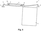
- Fig. 5 Now shows another exemplary embodiment of a sliding door module / sliding door module 1, in which the guide carriages 4 are pivotally connected to the cross member 5 and the door leaf 2, respectively.
- pivot bearing 14 is shown on both guide carriages 4.
- the shows Fig. 5 that not necessarily a fixed bearing and a floating bearing for the storage of the carrier 3 must be provided. Instead, two fixed bearings can be provided at the bearing points 7 and 8.
- the shows Figure 5 Also that a sliding door module / sliding door module 1 must not necessarily be made double-leaf, but may include only one door 2.
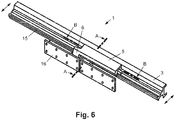
- FIGS. 6 and 7 now show an exemplary guide system for a sliding door module / sliding door module in a more detailed representation in an oblique view ( Fig. 6 ) as well as in the oblique section ( Fig. 7 ).
- the guide system comprises the carrier 3 as well as the linear roller guides with two profiled rails 15, which are fastened on the carrier 3 (for example screwed to it) or are enclosed by it in the form of a profile area.
- the profile rail 15 has in this example a substantially C-shaped or U-shaped cross-section, wherein a guide carriage 4 is mounted between the opposite end legs of the C-shaped or U-shaped cross-section.
- this special guide rail 15 is not mandatory, and it can also be used other types of linear roller guideways.
- the guide system comprises a cross member 6 with a console 6 fixedly connected thereto, on which a mounting plate 16 for a door 2 by means of a bolt 17 is rotatably mounted.
- the rail 15 extends in the Fig. 6 not over the entire length of the carrier 3. Of course, but this may be the case.
- the carrier 3 is slidably mounted transversely to its longitudinal extent in the horizontal direction which in the Fig. 6 symbolized by the laterally arranged double arrows.
- the carrier 3 is issued transversely to the sliding direction of the door, so that the door leaves can be moved.
- the carrier 3 can also be fixedly connected to the rail vehicle.
- a first rail 15 is mounted on the upper side of the carrier 3 and a second rail 15 on the underside of the carrier 3.
- a single carrier 3 can be used for holding a double-wing sliding door.
- the carrier 3 is constructed symmetrically with respect to the horizontal plane, since then no special mounting direction is observed.
- the profile rails 15 extend beyond the carrier 3 in this example in the mounting region of the rails 15 in the vertical direction.
- an imaginary connecting line of two rolling elements 9, which contact the mounting rail 15 and are in relation to a normal to the mounting surface aligned gravity axis 18 of the profile cross-section opposite each other, is oriented substantially horizontally.
- a circumferential plane of the rolling elements 9 is aligned substantially horizontally.
- an orbit 19 of the rolling elements 9 is arranged in the carriage 4.
- the depth of the guide system can be kept low.
- the shows Fig. 7 Also, that the rolling elements 9 are arranged in a single row between an end leg of the rail 15 and the carriage 4.
- the linear guide is particularly tolerant of deformation of the guide system or carrier 3 and thus particularly durable.
- the carrier 3 in the illustrated example is higher in cross-section on both sides of the profile rails 15 than in the region of the profile rail 15.
- the carrier 3 has an increase in cross-section on its top and bottom laterally of the rails 15.
- the carrier 3 thus has in this example a substantially H-shaped or X-shaped or T-shaped cross section.
- the vertical, on the other hand, the horizontal flexural rigidity of the carrier 3 can be significantly increased.
- the carrier 3 can also be made hollow. In particular, the cavity can be arranged in the neutral fiber of the carrier 3.
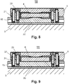
- FIGS. 8 and 9 show now two detailed embodiments for a pivot bearing 14 (see also Fig. 5 ).
- the Fig. 8 shows a section BB, from which it is apparent that the cross member 5 in the region of the guide carriage 4 has a convex portion which rests on the flat surface of the guide carriage 4, whereby a pivot or pivot bearing 14th is formed with two rolling surfaces rolling on each other. Because the guide carriage 4 is generally made of high-strength and hardened steel, the upper side of a commercially available guide carriage can act as a rolling surface without any further measures.
- the rolling surface arranged on the cross member 5 has a cylindrical shape, the projecting members standing normally on the sheet plane.
- the cross member 5 and thus an attached door leaf 2 can thus be rotated about a substantially horizontal and transverse to the sliding direction of rotation axis relative to the rail 15, whereby vertical deflections of the rail 15 can be compensated.
- the two rolling surfaces are pressed together by a weight force of the door leaf 2.
- the two rolling rolling surfaces are secured against lifting by means of an optional counter-holder 20.
- the counter-holder 20 is fixed in position relative to the cross member 5 by means of dowels 21 and screwed by means of screws 22 with this.
- the counter-holder 20 may be convex and / or a slight clearance be allowed. In the latter case, a lifting of the upper Wälzvid is therefore possible in principle, however, the "drop height" (ie the game) is chosen so low that damage to the Wälzvidin when striking the cross member 5 can be avoided on the carriage 4.
- Fig. 9 shows a variant of the guide system
- the in Figure 8 variant is very similar.
- the optional counter-holder 20 presses the rolling surfaces together by means of a spring force and / or by elastic deformation.
- the cross member 5 is bolted to the anvil 20 to two rubber buffers 23 which allow rolling of the rolling surfaces under moderate effort, but prevent lifting of the rolling surfaces or at least complicate.
- the anvil 20 has no convex portion, but of course it is also conceivable that he as in Fig. 8 is shown formed, whereby a rolling of the rolling surfaces is facilitated.
- joints allow a rotation of the cross member 5 relative to the rail 15 about a substantially horizontally and transversely directed to the sliding axis of rotation
- the joints shown by appropriate arrangement also for rotation about a vertical axis of rotation or aligned about a substantially parallel to the sliding direction Rotary axis can be provided.
- Fig. 10 shows very simplified a pivot 14 that allows rotation about two axes of rotation.
- the cross member 5 and the optional counter-holder 20 generally cylindrical rolling surfaces with mutually transverse axes.
- Such a hinge 14 can thus compensate for the deformations of a rail 15 respectively of the carrier 3 particularly well. Because of the linear contact of the rolling surfaces also comparatively high forces can be transmitted.
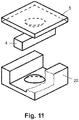
- Fig. 11 shows very simplified a pivot 14 that allows rotation about any axis of rotation.
- the cross member 5 and the optional counter-holder 20 have multi-dimensionally curved rolling surfaces, in particular spherical rolling surfaces.
- Such a hinge 14 can also compensate for the deformations of a rail 15 also particularly well. Because of the multi-dimensional curvature, the rolling surfaces can roll on each other when rotated about an arbitrary axis, whereby a mutual sliding is avoided and the wear of the rolling surfaces is thus reduced.
- a deformation of the rail 15 is made possible without the storage between guide carriage 4 and rail 15 to clamp.
- a carrier 3, on which the rail 15 is attached Therefore be made relatively fragile, since the door 2 always remains smooth despite a deformation of the rail 15 and damage in storage between carriage 4 and rail 15 are avoided.
- the provision of the bolt 17 can be dispensed with, that is, the rotation of the door leaf 2 about an axis extending in the longitudinal direction of the support 3 can - at least in a certain angular range - are also taken over by the hinge 14.
- a (further) rolling surface which allows rotation about the said longitudinal axis.
- the in the FIGS. 8 to 11 Specifically illustrated articulated bearings of the cross member 5 can be made in particular when the rail 15 is mounted only at the ends, so that the cross member 5 may include the carriage 4 together with the anvil 20 on all sides (see in particular Fig. 10 and 11 ). If the rail 15 such as in the Fig. 6 represented on the entire length of the carrier 3 are connected, for example, the counter-holder 20 omitted or the carriage 4 have a corresponding extension, which in turn can be encompassed by the cross member 5 together with the anvil 20 on all sides. In the in the FIGS. 8 and 9 arrangements shown, said extension can be arranged in particular laterally on the carriage 4, in which in the Figures 10 and 11 shown arrangements in particular extend in the longitudinal direction.
- vertical deflections of the rail 15 can be compensated for by allowing a rotation of the bracket 6 relative to the rail 15 about a substantially horizontally and transversely aligned to the sliding axis rotation, horizontal deflections by allowing rotation about a substantially vertically oriented axis of rotation and twisting of the rail 15 by allowing a rotation about a substantially parallel to the sliding direction aligned axis of rotation.
- rotations about several axes can be achieved by means of single pivot joints connected in series (cf. Fig. 5 and 7 ) and / or be realized by hinges that allow rotations about multiple axes (see Fig. 10 and 11 ).
- the hinges can also be realized optionally by successive rolling surfaces and / or against each other sliding surfaces (eg pin / slide bushing).
- the positioning is the joints, as indicated in the above examples, although advantageous but by no means mandatory.
- a rotary joint 14 may be provided in the carriage 4, between the cross member 5 and guide carriage 4, in the console 6, between the console 6 and door 2 and / or in the door 2 itself. In the latter case, for example, a mounting surface of the door leaf 2, to which the bracket 6 is attached, be hinged to the actual door 2.
- compensating joints 14 is of course not bound to a linear roller guide, although there may be a damaging consequence particularly quickly a distortion of the storage.
- the invention is equally applicable to linear sliding guides of all kinds.
- Fig. 2 It should be noted that the maximum deflection y2 of the carrier 3 can also relate to the outermost points of the guide carriages / guide carriages 4 carrying a door leaf 2. The guide length f, or the total guide length g is then measured on the outside of the guide carriages / guide carriages 4 and not on the rolling elements 9.
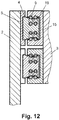
- Fig. 12 shows an example of a sliding door module / sliding door module 1, in which two door leaves 2 are attached via brackets 6 to the guide carriages / guide slide 4 of two linear guides arranged one above the other.
- the above teaching is mutatis mutandis applicable to such an arrangement.
- the guide carriages / guide carriages 4 may be used in the in Fig. 5 shown sliding door module / sliding door module 1 also be rigidly connected to the cross member 5.
- the guide carriages / guide carriages 4 may be used in the Fig. 1 shown sliding door module / sliding door module 1 also be hingedly connected to the cross member 5.
- This in Fig. 1 shown sliding door module / sliding door module 1 may also have two fixed bearing, whereas in Fig. 5 shown sliding door module / sliding door module 1 may also have a fixed bearing and a floating bearing.
- the illustrated sliding door module / sliding sliding door modules 1 can have a guide carriage / guide carriage 4 per door leaf 2 or else two or more guide carriages / guide carriages 4 per door leaf 2.
- a sliding door module / sliding door module 1 may in reality also comprise more or fewer components than illustrated.
Description
Die Erfindung betrifft ein Schiebetürmodul/Schwenkschiebetürmodul für ein Schienenfahrzeug, umfassend zumindest einen Türflügel, einen in Schieberichtung des Türflügels längs ausgerichteten Träger, welcher insbesondere quer zu seiner Längserstreckung in horizontaler Richtung verschiebbar gelagert ist, und eine Linearführung mit einer Profilschiene und wenigstens einem Führungswagen/Führungsschlitten. Die Profilschiene ist auf dem Träger befestigt oder von diesem in Form eines Profilbereichs umfasst. Der wenigstens eine Führungswagen/Führungsschlitten ist auf der Profilschiene gelagert, und der Türflügel ist mit Hilfe des zumindest einen Führungswagens/Führungsschlittens verschiebbar gelagert. Ein derartiger Schwenkschiebetürmodul ist beispielsweise aus der
Schiebetürmodule/Schwenkschiebetürmodule der genannten Art sind grundsätzlich bekannt. Dabei sind zumeist ein Türflügel oder zwei Türflügel verschiebbar gelagert, welche zum Öffnen im Falle eines Schwenkschiebetürmoduls mit Hilfe einer Ausstellmechanik zuerst ausgestellt und dann verschoben werden oder im Falle eines Schiebetürmoduls nur verschoben werden. Zugunsten eines leichtgängigen Betriebs sind die Türflügel in aller Regel mit Hilfe von Linearwalzführungen gelagert. Diese Linearwalzführungen sind hauptsachlich aus dem Bau von Werkzeugmaschinen bekannt, bei dem die exakte Führung von Maschinenteilen unerlässlich ist. Diese sind daher möglichst spielfrei ausgelegt und verlangen nach einer vergleichsweise starren Unterkonstruktion, um ein Verspannen der Linearwalzführungen zu vermeiden und eine lange Lebensdauer sicherzustellen. Die nach dem Stand der Technik eingesetzten Konstruktionen sind daher ebenfalls vergleichsweise starr ausgelegt, wodurch Stoße, die auf das Schienenfahrzeug einwirken, praktisch ungemildert auf das Schiebetürmodul/Schwenkschiebetürmodul übertragen werden. Dadurch wird wiederum die Lebensdauer der Linearführung verringert. Zudem sind die bekannten Losungen vergleichsweise schwer und wirken sich somit negativ auf das Gesamtgewicht des Schienenfahrzeugs aus. Insbesondere im urbanen Verkehr, bei dem die Schienenfahrzeuge in kurzen Abstanden beschleunigt und wieder abgebremst werden, verschlechtert eine solche Tragkonstruktion die Energieeffizienz des Schienenfahrzeugs.The invention relates to a sliding door module / sliding door module for a rail vehicle, comprising at least one door, a longitudinally oriented in the sliding direction of the door carrier, which is mounted in particular displaceable transversely to its longitudinal extent in the horizontal direction, and a linear guide with a rail and at least one carriage / guide carriage , The profile rail is fastened on the support or comprises it in the form of a profile region. The at least one carriage / guide carriage is mounted on the rail, and the door is slidably mounted by means of at least one guide carriage / guide carriage. Such a sliding door module is for example from the
Sliding door modules / sliding sliding door modules of the type mentioned are basically known. In this case, usually a door or two leaves are slidably mounted, which are first issued to open in the case of a sliding door module with the help of a release mechanism and then moved or only be moved in the case of a sliding door module. For ease of operation, the doors are usually stored with the help of linear roller guides. These linear roller guides are mainly known from the construction of machine tools, in which the exact guidance of machine parts is essential. These are therefore designed as free of play and require a relatively rigid substructure to avoid distortion of the linear roller guides and ensure a long life. Therefore, the constructions used in the prior art are also designed to be relatively rigid, so that shocks acting on the rail vehicle, virtually unmitigated transmitted to the sliding door module / sliding door module. This in turn reduces the life of the linear guide. In addition, the known solutions are relatively heavy and thus have a negative effect on the overall weight of the rail vehicle. Especially in urban traffic, in which the rail vehicles are accelerated and braked at short distances, such a support structure degrades the energy efficiency of the rail vehicle.
Eine Aufgabe der Erfindung ist es daher, ein verbessertes Schiebetürmodul/Schwenkschiebetürmodul anzugeben. Insbesondere sollen die oben beschriebenen Nachteile vermieden oder deren Auswirkungen wenigsten gemildert werden.An object of the invention is therefore to provide an improved sliding door module / sliding door module. In particular, the disadvantages described above should be avoided or their effects should be least mitigated.
Die Aufgabe der Erfindung wird mit einem Schiebetürmodul/Schwenkschiebetürmodul der eingangs genannten Art gelöst, bei dem die maximale statische Durchbiegung des Trägers bezogen auf dessen Lagerpunkte bei (leicht) geöffnetem Türflügel im Bereich einer lichten Türweite LW von 800 mm bis 2300 mm zumindest ![]()
![]()
Millimeter pro Kilogramm Türflügelgewicht beträgt. Die maximale statische Durchbiegung wird dabei bei stillstehendem Schienenfahrzeug gemessen und tritt an einer bestimmten Position des Trägers bei einer bestimmten Position des Türflügels oder der Türflügel auf. In aller Regel tritt die stärkste Durchbiegung des Trägers bei einer doppelflügeligen Schiebetür in der Mitte des Trägers bei leicht (einen Spalt weit) geöffneten Türflügeln und bei einer einflügeligen Schiebetür in der Mitte des Trägers bei halb geöffneter Schiebetür auf und kann exakt beispielsweise in einer Computersimulation oder einem Versuch ermittelt werden.Millimeters per kilogram door weight is. The maximum static deflection is measured when the rail vehicle is stationary and occurs at a certain position of the carrier at a specific position of the door leaf or the door leaf. In general, the strongest deflection of the carrier occurs in a double-leaf sliding door in the middle of the carrier at slightly (a crack) open doors and a single-leaf sliding door in the middle of the carrier with half open sliding door and can exactly, for example in a computer simulation or be determined in an attempt.
Die "lichte Türweite" bezeichnet die Breite des Durchgangs bei vollständig geöffneter Schiebetür und wird, je nachdem wie weit die der oder die Türflügel geöffnet wird/werden, zwischen dem Türrahmen, dem Türrahmen und einem Türflügel oder zwischen den beiden Türflügeln gemessen.The "clear door width" refers to the width of the passage when the sliding door is fully open and is measured between the door frame, the door frame and a door leaf or between the two door leaves, depending on how far the door leaf (s) are opened.
Die Durchbiegung ist bezogen auf das Gewicht des Türflügels respektive der Türflügel angegeben. Um die absolute Durchbiegung zu erhalten, ist der angegebene Wert jeweils mit dem Gesamtgewicht der Türflügel zu multiplizieren. Beträgt das Gewicht eines Türflügels beispielsweise 32,5 kg und handelt es sich um eine doppelflügelige Schiebetür mit einer lichten Weite von 1600 mm, so ergibt sich eine maximale absolute statische Durchbiegung des Trägers von zumindest ![]()
![]()
![]()
![]()
Weiterhin ist es günstig, wenn die maximale statische Durchbiegung des Trägers bezogen auf dessen Lagerpunkte bei geöffnetem Türflügel im Bereich einer lichten Türweite LW von 800 mm bis 2300 mm zumindest ![]()
![]()
![]()
![]()
Günstig ist es zudem, wenn die maximale statische Durchbiegung des Trägers zwischen den äußersten Berührpunkten der den Türflügel tragenden Führungswägen/Führungsschlitten mit der Profilschiene (das heißt auf der Gesamt-Führungslänge) bei geöffnetem Türflügel zusätzlich oder alternativ zumindest 0,0075 mm, insbesondere aber auch 0,015 mm, 0,030 mm oder sogar 0,075 mm pro kg Türflügelgewicht beträgt. Handelt es sich bei der Linearführung um eine Linearwälzführung, so kann die maximale statische Durchbiegung des Trägers auch auf die Berührpunkte der äußersten, den Türflügel tragenden Wälzkörper mit der Profilschiene bezogen sein. Auch hier kann die absolute Durchbiegung durch Multiplikation des angegebenen Werts mit dem Gesamtgewicht der Türflügel erhalten werden.It is also advantageous if the maximum static deflection of the carrier between the outermost points of contact of the door carrying the carriage guide carriage / guide carriage with the rail (ie on the total guide length) with the door open additionally or alternatively at least 0.0075 mm, but especially 0.015 mm, 0.030 mm or even 0.075 mm per kg of door leaf weight. If the linear guide is a linear roller guide, then the maximum static deflection of the carrier can also be related to the contact points of the outermost rolling elements bearing the door leaf with the profile rail. Again, the absolute deflection can be obtained by multiplying the specified value by the total weight of the leaves.
Gegenüber aus dem Stand der Technik bekannten Schiebetürmodulen/Schwenkschiebetürmodulen weist das vorgestellte Schiebetürmodul/Schwenkschiebetürmodul eine vergleichsweise starke Verformung auf. Der Träger des Schiebetürmodul/Schwenkschiebetürmoduls ist also gezielt "weich" gestaltet, sodass dieser im Wesentlichen wie eine Blattfeder wirkt und auf diese Weise die Übertragung von auf das Schienenfahrzeug wirkenden Stößen auf das Schiebetürmodul/Schwenkschiebetürmodul gemildert wird. Dadurch dass auf die Linearführung Stöße kaum mehr einwirken, weist dies eine erhöhte Lebensdauer auf. Durch das reduzierte Gewicht des Trägers werden nicht nur die Energieeffizienz des Schienenfahrzeugs verbessert, sondern es wird auch die Resonanzfrequenz des Schiebetürmoduls/Schwenkschiebetürmoduls in Richtung höherer Frequenzen verschoben, wodurch Schwingungen mit nennenswerter Amplitude nicht oder in nur geringem Maße angeregt werden können.Compared with sliding door modules known from the prior art / sliding sliding door modules, the presented sliding door module / sliding sliding door module has a comparatively high degree of deformation. The support of the sliding door module / sliding door module is so targeted "soft" designed so that it acts essentially as a leaf spring and thus mitigated the transmission of impacts acting on the rail vehicle bumps on the sliding door module / sliding door module becomes. Due to the fact that impacts no longer act on the linear guide, this has an increased service life. The reduced weight of the carrier not only improves the energy efficiency of the rail vehicle, but also shifts the resonant frequency of the sliding door module / sliding door module toward higher frequencies, which can not or only to a limited extent excite vibrations of appreciable amplitude.
Die vorgestellte Lösung kann sowohl bei einer Linearwälzführung, bei der ein Führungswagen mit Hilfe von Wälzkörpern auf einer Profilschiene gelagert ist, als auch bei einer Lineargleitführung, bei der ein Führungsschlitten auf der Profilschiene gleitet, eingesetzt werden. Linearwälzführungen bieten eine gute Leichtgängigkeit bei nur geringem oder keinem Lagerspiel, allerdings sind sie aufgrund der hohen Flächenpressungen zwischen Wälzkörper und Profilschiene sehr anfällig gegen Überbelastung, insbesondere Stöße. Durch die weiche Gestaltung des Trägers werden solche Stöße aber sehr gut gedämpft, wodurch der Vorteil der Erfindung bei Verwendung von Linearwälzführungen besonders hervortritt.The proposed solution can be used both in a linear roller guide, in which a carriage is mounted with the aid of rolling elements on a rail, as well as in a linear sliding guide in which slides a guide carriage on the rail. Linear roller guides offer good ease of movement with little or no clearance, but they are very susceptible to overloading, especially shocks due to the high surface pressures between rolling elements and rail. Due to the soft design of the carrier but such shocks are very well damped, whereby the advantage of the invention when using linear roller guideways particularly stands out.
Linearwälzführungen können zum Beispiel mit Kugeln oder Rollen als Wälzkörper ausgeführt werden. Die Wälzkörper bilden in einem Kontaktbereich das Bindeglied zwischen Profilschiene und Führungswagen. Die momentan nicht in Kontakt mit der Profilschiene stehenden Wälzkörper werden über einen Rückführbereich (z.B. Rückführkanal) vom Ende des Kontaktbereichs zu dessen Beginn oder umgekehrt geleitet. Die Wälzkörper wandern also in einer geschlossenen Bahn. In aller Regel ist diese Bahn im Wesentlichen in einer Ebene, der "Umlaufebene" angeordnet. Dabei kann eine ovalförmige Bahn vorgesehen sein, oder es sind hintereinander mehrere ovalförmige oder kreisförmige Bahnen vorgesehen, die in derselben Ebene angeordnet sind und in ihrer Gesamtheit einen Kontaktbereich bilden. Darüber hinaus können mehrere Bahnen auch in unterschiedlichen aber zueinander parallelen Ebenen liegen. Schließlich können die Bahnen auch einander kreuzen. Beispielsweise kann eine Umlaufbahn die Umlaufebene im Umkehrbereich verlassen, um eine Kreuzung mit einer anderen Umlaufbahn zu ermöglichen. Gegebenenfalls können die Wälzkörper auch in einem Wälzkörperkäfig angeordnet sein.Linear roller guides can be designed, for example, with balls or rollers as rolling elements. The rolling elements form the link between the profile rail and guide carriage in a contact area. The rolling elements not currently in contact with the rail are directed via a return area (e.g., return duct) from the end of the contact area to the beginning thereof or vice versa. The rolling elements thus move in a closed path. As a rule, this orbit is arranged essentially in one plane, the "orbital plane". In this case, an oval-shaped path may be provided, or there are successively provided a plurality of oval-shaped or circular tracks, which are arranged in the same plane and form a contact area in their entirety. In addition, multiple tracks may also be in different but parallel planes. Finally, the tracks can also cross each other. For example, an orbit may leave the orbital plane in the reverse region to allow for intersection with another orbit. Optionally, the rolling elements can also be arranged in a rolling element cage.
An dieser Stelle wird angemerkt, dass sich die Merkmale der Erfindung im Besonderen für den Einsatz bei einer Schwenkschiebetüre beziehungsweise bei einem Schwenkschiebemodul eignen. Nichtsdestotrotz kann die Erfindung auch für eine Schiebetür beziehungsweise ein Schiebetürmodul eingesetzt werden, bei der oder dem ein Schwenkmechanismus fehlt.It should be noted at this point that the features of the invention in particular for use in a sliding door or a sliding module suitable. Nevertheless, the invention can also be used for a sliding door or a sliding door module in which or a pivot mechanism is missing.
Weitere vorteilhafte Ausgestaltungen und Weiterbildungen der Erfindung ergeben sich aus den Unteransprüchen sowie aus der Beschreibung in Zusammenschau mit den Figuren.Further advantageous embodiments and modifications of the invention will become apparent from the dependent claims and from the description in conjunction with the figures.
Vorteilhaft ist es, wenn das Schiebetürmodul/Schwenkschiebetürmodul mehrere (z.B. zwei) gesonderte, insbesondere in Schieberichtung des Türflügels von einander beabstandete, nur einem Türflügel zugeordnete Führungswägen/Führungsschlitten aufweist. Insbesondere sind die genannten Führungswägen/Führungsschlitten auf nur einer Profilschiene gelagert. Im Prinzip können einem Türflügel aber auch mehrere Führungswägen/Führungsschlitten, welche auf unterschiedlichen Profilschienen gelagert sind, zugeordnet sein. Auf diese Weise kann das durch die Gewichtskraft des Türflügels verursachte Drehmoment wegen der beabstandeten Führungswägen/Führungsschlitten gut in den Träger übertragen werden, andererseits ist die Linearführung aufgrund der relativ kurzen Führungslänge der einzelnen Führungswägen/Führungsschlitten aber auch wenig anfällig gegen Verspannungen.It is advantageous if the sliding door module / sliding sliding door module has a plurality of (for example two) separate, in particular in the sliding direction of the door leaf from each other spaced, only one door associated with guide carriage / guide carriage. In particular, said guide carriages / guide carriages are mounted on only one rail. In principle, however, a door leaf can also be assigned a plurality of guide carriages / guide carriages which are mounted on different profile rails. In this way, the torque caused by the weight of the door leaf due to the spaced guide carriages / guide slides are well transferred to the carrier, on the other hand, the linear guide is due to the relatively short guide length of the individual guide carriages / guide carriage but also less susceptible to tension.
Vorteilhaft ist es in obigem Zusammenhang insbesondere, wenn die Führungslängen der Führungswägen/Führungsschlitten in Summe maximal halb so lang sind wie die Gesamt-Führungslänge, also der Abstand zwischen den äußersten Berührpunkten der den Türflügel tragenden Führungswägen/Führungsschlitten mit der Profilschiene. Dadurch bleibt die Lagerung der Führungswägen/Führungsschlitten auch bei vergleichsweise starker Durchbiegung des Trägers respektive der Profilschiene leichtgängig. Im Falle einer Linearwälzführung können die Führungslänge und die Gesamt-Führungslänge wiederum auf die äußersten, den Türflügel tragenden Wälzkörper bezogen sein.It is advantageous in the above context, in particular, if the guide lengths of the guide carriages / guide carriages are at most half as long as the total guide length, ie the distance between the outermost points of contact of the guide carriages / guide carriages carrying the door leaf with the profile rail. As a result, the storage of the guide carriages / guide carriage remains smooth even with relatively strong deflection of the carrier or the rail. In the case of a linear roller guide, the guide length and the total guide length can in turn be related to the outermost, the door leaf-bearing rolling elements.
Günstig ist es, wenn die Führungswägen/Führungsschlitten starr mit einem Querträger respektive gelenkig mit dem Türflügel miteinander verbunden sind. Dadurch ergibt sich eine einfache und robuste Konstruktion des Schiebetürmoduls/Schwenkschiebetürmoduls.It is advantageous if the guide carriages / guide carriages are rigidly connected to one another with a cross member, respectively, in an articulated manner with the door leaf. This results in a simple and robust construction of the sliding door module / sliding door module.
Günstig ist es, wenn die Führungswägen/Führungsschlitten gelenkig mit einem Querträger respektive gelenkig mit dem Türflügel miteinander verbunden sind. Auf diese Weise kann eine Durchbiegung des Trägers noch besser ausgeglichen werden, da die Führungswägen/Führungsschlitten einer lokalen Ausrichtung des Trägers respektive der Führungsschiene besser folgen können und das Risiko einer Verspannung der Linearführung damit reduziert wird.It is advantageous if the guide carriages / guide carriages are articulated to one another with a cross member respectively hinged to the door leaf. In this way, a deflection of the carrier can be compensated even better, since the guide carriages / guide carriages a local orientation of the carrier respectively the guide rail can follow better and the risk of distortion of the linear guide is thus reduced.
Günstig ist es, wenn der Träger bezogen auf seine Längserstreckung im Wesentlichen an seinen Endpunkten gelagert ist. Auf diese Weise kann eine vergleichsweise gute Dämpfungswirkung von auf das Schienenfahrzeug einwirkenden Stößen erzielt werden. Darüber hinaus ergibt sich bei dieser Anordnung in aller Regel eine vorteilhafte Einbausituation.It is favorable if the carrier is mounted essentially at its end points in relation to its longitudinal extent. In this way, a comparatively good damping effect of impacts acting on the rail vehicle can be achieved. In addition, in this arrangement usually results in a favorable installation situation.
Besonders günstig ist es aber auch, wenn der Träger bezogen auf seine Längserstreckung im Wesentlichen an den Besselschen Punkten gelagert ist. Dadurch kann das Gewicht des Trägers bei gleicher Dämpfungswirkung reduziert werden. Die Bessel-Punkte sind vorteilhafte Positionen der Auflager eines belasteten Trägers und liegen etwa bei 22% der Länge des Trägers. Deren konkrete Position hängt jedoch von der Auslegung des Trägers und der darauf montierten Komponenten sowie von der Gewichtsverteilung ab.But it is also particularly advantageous when the carrier is mounted relative to its longitudinal extent substantially at the Bessel points. As a result, the weight of the carrier can be reduced with the same damping effect. The Bessel points are advantageous positions of the supports of a loaded beam and are about 22% of the length of the beam. However, their specific position depends on the design of the carrier and the components mounted thereon and on the weight distribution.
Besonders günstig ist es auch, wenn einer der Lagerpunkte des Träger als Fixlager und der andere Lagerpunkt oder die anderen Lagerpunkte als Loslager ausgebildet ist/sind. Auf diese Weise kann eine zum Beispiel temperaturbedingte Längenänderung des Trägers beziehungsweise ein Änderung der Distanz zwischen den Endpunkten des Trägers bei Durchbiegung desselben ausgeglichen werden.It is also particularly favorable if one of the bearing points of the carrier is designed as a fixed bearing and the other bearing point or the other bearing points as a movable bearing is / are. In this way, for example, a temperature-induced change in length of the wearer or a change in the distance between the end points of the support in deflection of the same can be compensated.
Vorteilhaft ist es, wenn der Träger im Querschnitt beidseits der Profilschiene höher ist als im Bereich der Profilschiene. Insbesondere weist der Träger im Querschnitt auf seiner Ober- und Unterseite seitlich von der Profilschiene dazu eine Erhöhung auf. Im Speziellen kann der Träger auch einen im Wesentlichen H-förmigen oder X-förmigen oder T-förmigen Querschnitt aufweisen. Dadurch kann einerseits die vertikale, andererseits auch die horizontale Biegesteifigkeit des Trägers bei gleichem Gewicht erhöht oder sein Gewicht bei gleicher Biegesteifigkeit verringert werden. Der Träger kann somit insgesamt relativ dünnwandig gestaltet werden, wodurch das Gesamtgewicht des Schiebetürmoduls/Schwenkschiebetürmoduls weiter reduziert und damit die Fahrleistungen des Schienenfahrzeugs verbessert werden. Neben der Verbesserung des Schiebetürmoduls/Schwenkschiebetürmoduls im Hinblick auf vertikale Kräfte wird auch eine Erhöhung der Biegesteifigkeit in horizontaler Richtung beziehungsweise eine Erhöhung der Torsionssteifigkeit um die Längsachse des Trägers bewirkt.It is advantageous if the carrier in cross section on both sides of the rail is higher than in the region of the rail. In particular, the carrier has in cross-section on its top and bottom laterally from the rail to an increase. In particular, the carrier may also have a substantially H-shaped or X-shaped or T-shaped cross-section. As a result, on the one hand increases the vertical, on the other hand, the horizontal flexural rigidity of the wearer with the same weight or its weight can be reduced with the same flexural rigidity. The carrier can thus be made overall relatively thin-walled, whereby the total weight of the sliding door module / sliding door module is further reduced and thus the performance of the rail vehicle can be improved. In addition to improving the sliding door module / sliding door module with respect to vertical forces an increase in the bending stiffness in the horizontal direction or an increase in the torsional stiffness about the longitudinal axis of the carrier is also effected.
Günstig ist es auch, wenn der Träger im Bereich der neutralen Biegefaser einen Hohlraum aufweist, das heißt die neutrale Faser im genannten Hohlraum angeordnet ist. Dadurch weist der Träger ein relativ geringes Gewicht bei guter Stabilität auf.It is also favorable if the carrier has a cavity in the region of the neutral bending fiber, that is, the neutral fiber is arranged in said cavity. As a result, the carrier has a relatively low weight with good stability.
Besonders vorteilhaft ist es, wenn das Führungssystem zwei Linearführungen umfasst, wobei eine erste Profilschiene auf der Oberseite des Trägers und eine zweite Profilschiene auf der Unterseite des Trägers montiert sind. Auf diese Weise kann ein einziger Träger zum Halten einer doppelflügeligen Schwenkschiebetür eingesetzt werden. Ein Schiebetürmodul/Schwenkschiebetürmodul umfasst dementsprechend eine der unteren Linearführung befestigte erste Schwenkschiebetür und eine an der oberen Linearführung befestigte zweite Schwenkschiebetür. Die Bauhöhe des Führungssystems ist bei dieser Anordnung besonders gering. Insbesondere ist es auch von Vorteil, wenn der Träger in Bezug auf seine Horizontalachse symmetrisch aufgebaut ist, da dann keine besondere Montagerichtung zu beachten ist.It when the guide system comprises two linear guides, wherein a first rail on the top of the carrier and a second rail are mounted on the underside of the carrier is particularly advantageous. In this way, a single carrier can be used for holding a double-wing sliding door. A sliding door module / sliding door module accordingly comprises a first pivot sliding door fixed to the lower linear guide and a second pivot sliding door attached to the upper linear guide. The height of the guide system is particularly low in this arrangement. In particular, it is also advantageous if the carrier is constructed symmetrically with respect to its horizontal axis, since then no special mounting direction is observed.
Vorteilhaft ist es, wenn die Profilschiene einen im Wesentlichen C-förmigen beziehungsweise U-förmigen Querschnitt aufweist und der Führungswagen/Führungsschlitten zwischen den gegenüberliegenden Endschenkeln des C-förmigen beziehungsweise U-förmigen Querschnitts gelagert ist. Eine solche Linearwälzführung ist kaum anfällig im Hinblick auf Verspannungen, wodurch diese bei Einsatz in dem vorgestellten Schiebetürmodul/Schwenkschiebetürmodul eine vergleichsweise hohe Lebensdauer aufweist.It is advantageous if the profile rail has a substantially C-shaped or U-shaped cross-section and the guide carriage / guide carriage is mounted between the opposite end legs of the C-shaped or U-shaped cross section. Such a linear roller guide is hardly susceptible to tension, whereby this has a comparatively long life when used in the proposed sliding door module / sliding door module.
Besonders vorteilhaft ist es weiterhin in obigem Zusammenhang, wenn die Wälzkörper zwischen einem Endschenkel der Profilschiene und dem Führungswagen/Führungsschlitten einreihig angeordnet sind. Dadurch ist die Linearführung besonders tolerant gegenüber Verformungen des Führungssystems und damit besonders gut für den Einsatz bei Schienenfahrzeugen geeignet. Aus den genannten Gründen ist die Linearführung zudem sehr langlebig.It is also particularly advantageous in the above context, when the rolling elements are arranged in a single row between an end leg of the rail and the carriage / guide carriage. As a result, the linear guide is particularly tolerant to deformations of the guide system and thus particularly well suited for use in rail vehicles. For the reasons mentioned, the linear guide is also very durable.
Besonders vorteilhaft ist es, wenn ein Antrieb für den Türflügel derart dimensioniert ist, dass die Durchbiegung des Trägers beim Schließen des Türflügels verringert wird. Ein wegen der Durchbiegung des Trägers nach außen hängender Türflügel wird beim Schließen gegen den Türrahmen oder eine andere Schiebetür gefahren und bei weiterer Einwirkung des ausreichend stark dimensionieren Antriebs aufgerichtet. Durch den Berührpunkt des Türflügels mit dem Türrahmen oder einem anderen Türflügel und die auf ihn wirkende Antriebskraft wirkt ja ein Drehmoment auf diesen. Dadurch wird aber auch der Träger in dessen Mitte nach oben gedrückt, sodass die Durchbiegung verringert wird. Durch diese Verspannung wird nicht nur die Durchbiegung des Trägers verringert, sondern auch das Schwingungsverhalten des Schiebetürmoduls/Schwenkschiebetürmoduls verändert, das heißt in Richtung höherer Resonanzfrequenzen verschoben. Man kann also sagen, dass das Schwingungsverhalten des Schiebetürmoduls/Schwenkschiebetürmoduls über den Antrieb für die Türflügel gesteuert werden kann. Als Antrieb kommen alle Arten von Rotationsmotoren oder Linearmotoren in Frage, beispielsweise elektrische, pneumatische und hydraulische Antriebe. Konkret kann die Tragkonstruktion für einen Türflügel beispielsweise mit Hilfe einer Spindel oder eines Seilzugs entlang des Trägers bewegt werden.It is particularly advantageous if a drive for the door leaf is dimensioned such that the deflection of the support when closing the door leaf is reduced. One because of the Deflection of the carrier hanging outward door is moved when closing against the door frame or other sliding door and erected upon further action of sufficiently strong drive. Due to the point of contact of the door leaf with the door frame or another door leaf and the driving force acting on it, a torque acts on it. As a result, however, the carrier is pushed in the middle of the top, so that the deflection is reduced. This tension not only reduces the deflection of the carrier but also alters the vibration behavior of the sliding door module / sliding sliding door module, that is to say displaces it in the direction of higher resonance frequencies. It can therefore be said that the vibration behavior of the sliding door module / sliding door module can be controlled via the drive for the door leaves. As drive all types of rotary motors or linear motors in question, for example, electric, pneumatic and hydraulic drives. Specifically, the support structure for a door can be moved, for example by means of a spindle or a cable along the carrier.
Günstig ist es schließlich auch, wenn der Türflügel um eine in Längsrichtung des Trägers verlaufende Achse drehbar gelagert ist. Dadurch können einerseits Toleranzen ausgeglichen werden, andererseits kann ein solches Schiebetürmodul/Schwenkschiebetürmodul auch gut in Schienenfahrzeuge eingebaut werden, deren Seitenwände geneigt sind. Die Drehung kann beispielsweise dadurch ermöglicht werden. dass der Türflügel mit Hilfe eines drehbar gelagerten Bolzens am Querträger befestigt wird. Vorstellbar ist aber auch, dass der Türflügel mit dem Querträger fix verbunden ist, dieser jedoch drehbar zur Profilschiene gelagert ist.Finally, it is also favorable if the door leaf is rotatably mounted about an axis running in the longitudinal direction of the carrier. As a result, on the one hand tolerances can be compensated, on the other hand, such a sliding door module / sliding door module can also be well installed in rail vehicles whose side walls are inclined. The rotation can be made possible, for example. that the door is fixed by means of a rotatably mounted bolt on the cross member. But it is also conceivable that the door is fixedly connected to the cross member, but this is rotatably mounted to the rail.
Zum besseren Verständnis der Erfindung wird diese anhand der nachfolgenden Figuren näher erläutert. Es zeigen
- Fig. 1
- ein beispielhaftes und stark vereinfachtes und mit übertriebener Verformung dargestelltes Schiebetürmodul/Schwenkschiebetürmodul eines Schienenfahrzeugs;
- Fig. 2
- den Träger und die Führungswägen des Schiebetürmoduls/Schwenkschiebetürmoduls isoliert dargestellt;
- Fig. 3
- einen Träger des Schiebetürmoduls/Schwenkschiebetürmoduls mit nur einem Führungswagen für einen Türflügel;
- Fig. 4
- wie
Fig. 1 , nur mit geschlossenen Türflügeln und dadurch verringerter Verformung des Schiebetürmoduls/Schwenkschiebetürmoduls; - Fig. 5
- ein Schiebetürmodul/Schwenkschiebetürmodul, bei dem ein zwei Führungswägen verbindender Querträger gelenkig mit diesen verbunden ist;
- Fig. 6
- ein beispielhaftes und schematisch dargestelltes Führungssystem für ein Schiebetürmodul/Schwenkschiebetürmodul in Schrägansicht;
- Fig. 7
- das Führungssystem aus
Fig. 1 im Querschnitt; - Fig. 8
- das Führungssystem aus
Fig. 1 im Längsschnitt; - Fig. 9
- wie
Fig. 8 , nur mit einem elastischen Element zwischen Konsole und Gegenhalter; - Fig. 10
- ein Gelenk mit allgemein zylindrischen Wälzflächen mit aufeinander quer stehenden Achsen;
- Fig. 11
- ein Gelenk mit mehrdimensional gewölbten Wälzflächen und
- Fig. 12
- ein Führungssystem mit vertikal angeordnetem Führungswagen.
- Fig. 1
- an exemplary and greatly simplified and with exaggerated deformation sliding door module / sliding door module of a rail vehicle;
- Fig. 2
- the carrier and the guide carriages of the sliding door module / sliding door module shown isolated;
- Fig. 3
- a carrier of the sliding door module / sliding door module with only one carriage for a door leaf;
- Fig. 4
- as
Fig. 1 , only with closed door leaves and thus reduced deformation of the sliding door module / sliding door module; - Fig. 5
- a sliding door module / sliding door module in which a cross member connecting two guide carriages is pivotally connected thereto;
- Fig. 6
- an exemplary and schematically illustrated guide system for a sliding door module / sliding door module in an oblique view;
- Fig. 7
- the leadership system
Fig. 1 in cross-section; - Fig. 8
- the leadership system
Fig. 1 in longitudinal section; - Fig. 9
- as
Fig. 8 , only with an elastic element between console and counterholder; - Fig. 10
- a joint with generally cylindrical Wälzflächen with successive transverse axes;
- Fig. 11
- a joint with multidimensionally curved rolling surfaces and
- Fig. 12
- a guide system with vertically arranged carriage.
Einführend sei festgehalten, dass in den unterschiedlich beschriebenen Ausführungsformen gleiche Teile mit gleichen Bezugszeichen bzw. gleichen Bauteilbezeichnungen versehen werden, wobei die in der gesamten Beschreibung enthaltenen Offenbarungen sinngemäß auf gleiche Teile mit gleichen Bezugszeichen bzw. gleichen Bauteilbezeichnungen übertragen werden können. Auch sind die in der Beschreibung gewählten Lageangaben, wie z.B. oben, unten, seitlich usw. auf die unmittelbar beschriebene sowie dargestellte Figur bezogen und sind bei einer Lageänderung sinngemäß auf die neue Lage zu übertragen. Weiterhin können auch Einzelmerkmale oder Merkmalskombinationen aus den gezeigten und beschriebenen unterschiedlichen Ausführungsbeispielen für sich eigenständige, erfinderische oder erfindungsgemäße Lösungen darstellen.By way of introduction, it should be noted that in the differently described embodiments, the same parts are provided with the same reference numerals or the same component names, wherein the disclosures contained in the entire description can be mutatis mutandis to the same parts with the same reference numerals or component names. Also, the position information selected in the description, such as top, bottom, side, etc. related to the immediately described and illustrated figure and are to be transferred to a new position analogous to the new situation. You can also continue Represent individual features or combinations of features from the illustrated and described different embodiments of their own, inventive or inventive solutions.
Sämtliche Angaben zu Wertebereichen in gegenständlicher Beschreibung sind so zu verstehen, dass diese beliebige und alle Teilbereiche daraus mit umfassen, z.B. ist die Angabe 1 bis 10 so zu verstehen, dass sämtliche Teilbereiche, ausgehend von der unteren Grenze 1 und der oberen Grenze 10 mit umfasst sind, d.h. sämtliche Teilbereich beginnen mit einer unteren Grenze von 1 oder größer und enden bei einer oberen Grenze von 10 oder weniger, z.B. 1 bis 1,7, oder 3,2 bis 8,1 oder 5,5 bis 10.All statements on ranges of values in the description of the present invention should be understood to include any and all sub-ranges thereof, e.g. is the
Im gezeigten Beispiel ist je ein Türflügel 2 je zwei Führungswägen 4 zugeordnet. Dazu sind diese über einen Querträger 5 starr miteinander verbunden. Der Türflügel 2 ist über eine Konsole 6 am Querträger 6 befestigt. In dem in
Der Träger 3 ist in dem konkreten Beispiel bezogen auf seine Längserstreckung im Wesentlichen an seinen Endpunkten gelagert. Dabei ist der linke Lagerpunkt des Träger 3 als Fixlager 7 und der rechte Lagerpunkt als Loslager 8 ausgebildet. Mit den beiden Lagern 7 und 8 ist der Träger 3 in einem Schienenfahrzeug (nicht dargestellt) gelagert.The
Wie in der ![]()
![]()
Millimeter pro Kilogramm Türflügelgewicht. Da der Träger 3 an seinen Enden an den Lagern 7 und 8 gelagert ist, tritt die maximale statische Durchbiegung y1 in der Mitte des Trägers 3 auf, im Speziellen wenn die Tür einen Spalt breit geöffnet ist. Je nach Lagerung des Trägers 3 kann die maximale statische Durchbiegung y1 aber auch an einer anderen Stelle des Trägers 3 auftreten. Die absolute Durchbiegung kann durch Einsetzen der lichten Weite in die Formel und durch Multiplikation des angegebenen Werts mit dem Gesamtgewicht der Türflügel erhalten werden.Millimeters per kilogram door weight. Since the
Zusätzlich oder alternativ dazu kann die maximale Durchbiegung y2 des Trägers 3 zwischen den Berührpunkten der äußersten, einen Türflügel 2 tragenden Wälzkörper mit der Profilschiene bei geöffneter Schiebetür zumindest 0,0075 mm, insbesondere zumindest 0,015 mm, 0,030 mm oder 0,075 mm pro kg Türflügelgewicht betragen. Die absolute Durchbiegung kann jeweils durch Multiplikation des angegebenen Werts mit dem Gesamtgewicht der Türflügel erhalten werden.Additionally or alternatively, the maximum deflection y2 of the
In der Realität treten an dem Träger 3 nicht nur Durchbiegungen in vertikaler sondern auch in horizontaler Richtung auf. Dies deswegen, weil auf die Türflügel 2 Druckschwankungen wirken und so den Träger 3 auch in horizontaler Richtung verbiegen können. Es kommt somit auch zu einem Biegemoment normal auf das in
Gegenüber aus dem Stand der Technik bekannten Schiebetürmodulen/Schwenkschiebetürmodulen weist das in den
Um das Gewicht des Trägers 3 bei gleicher Durchbiegung y1, y2 weiter zu reduzieren kann auch vorgesehen sein, dass die Lagerpunkte etwas nach innen versetzt werden. In der
In der
In einer weiteren Variante können auch mehrere (insbesondere zwei) Führungswägen 4 vorgesehen sein, die einander berühren. Die Gesamtlänge der Anordnung entspricht dann der Summe der Längen der einzelnen Führungswägen 4. Gegenüber der in
In einer vorteilhaften Variante des Schiebetürmoduls/Schwenkschiebetürmoduls 1 ist ein Antrieb für die Türflügel 2 derart dimensioniert, dass die Durchbiegung y1, y2 des Trägers 3 beim Schließen der Türflügel 2 verringert wird.
Man kann also sagen, dass das Schwingungsverhalten des Schiebetürmoduls/Schwenkschiebetürmoduls 1 über den Antrieb gesteuert werden kann. Als Antrieb kommen alle Arten von Rotationsmotoren oder Linearmotoren in Frage, beispielsweise elektrische, pneumatische und hydraulische Antriebe. Konkret kann die Tragkonstruktion 4, 5, 6 für einen Türflügel 2 beispielsweise mit Hilfe einer Spindel, eines Seilzugs oder eines Zahnstangenantriebs entlang des Trägers 3 bewegt werden.It can therefore be said that the vibration behavior of the sliding door module / sliding
Die
Weiterhin umfasst das Führungssystem einen Querträger 6 mit einer damit fix verbundenen Konsole 6, an der eine Montageplatte 16 für einen Türflügel 2 mit Hilfe eines Bolzens 17 drehbar gelagert ist. Die Profilschiene 15 erstreckt sich in der
Dabei wird der Träger 3 quer zur Schieberichtung des Türflügel ausgestellt, sodass die Türflügel verfahren werden können. Insbesondere bei einer solchen Bauweise ist auf geringes Gewicht der gesamten Anordnung zu achten, da dieses das Führungssystem des Trägers 3 (nicht dargestellt) vergleichsweise stark belastet. Der Träger 3 kann aber auch fix mit dem Schienenfahrzeug verbunden sein.In this case, the
In der
Gut zu sehen ist in
Wie insbesondere aus der
Aus der
Die
Die
Konkret weist die auf dem Querträger 5 angeordnete Wälzfläche eine zylindrische Form auf, wobei die Projizierenden normal auf die Blattebene stehen. Der Querträger 5 und damit ein daran befestigter Türflügel 2 können somit um eine im Wesentlichen horizontal und quer zur Schieberichtung ausgerichtete Drehachse gegenüber der Profilschiene 15 gedreht werden, wodurch vertikale Durchbiegungen der Profilschiene 15 ausgeglichen werden können.Concretely, the rolling surface arranged on the
In diesem Beispiel werden die beiden Wälzflächen durch eine Gewichtskraft des Türflügels 2 aneinander gepresst. Zusätzlich sind die zwei aufeinander abrollende Wälzflächen mit Hilfe eines optionalen Gegenhalters 20 gegen Abheben gesichert sind. Der Gegenhalter 20 wird mit Hilfe von Paßstiften 21 gegenüber dem Querträger 5 lagefixiert und mit Hilfe der Schrauben 22 mit dieser verschraubt. Um dennoch eine Drehung des Querträgers 5 gegenüber der Profilschiene 15 zu ermöglichen kann wie in
Prinzipiell ist es für die in der
Obwohl die in den
Durch das Vorsehen eines Drehgelenks 14 oder mehrere Drehgelenke 14 wird eine Verformung der Profilschiene 15 ermöglicht ohne die Lagerung zwischen Führungswagen 4 und Profilschiene 15 zu verspannen. Gegenüber bekannten Schiebetürmodulen/Schwenkschiebetürmodulen kann ein Träger 3, auf dem die Profilschiene 15 befestigt ist, daher vergleichsweise fragil gestaltet werden, da der Türflügel 2 trotz einer Verformung der Profilschiene 15 stets leichtgängig bleibt und Schäden in der Lagerung zwischen Führungswagen 4 und Profilschiene 15 vermieden werden. Darüber hinaus ist bei entsprechender Ausführung des Drehgelenks 14 das Vorsehen des Bolzens 17 entbehrlich, das heißt die Drehung des Türflügels 2 um eine in Längsrichtung des Trägers 3 verlaufende Achse kann - zumindest in einem gewissen Winkelbereich - auch vom Drehgelenk 14 übernommen werden. In der
Die in den
Generell können vertikale Durchbiegungen der Profilschiene 15 durch Zulassen einer Drehung der Konsole 6 gegenüber der Profilschiene 15 um eine im Wesentlichen horizontal und quer zur Schieberichtung ausgerichtete Drehachse ausgeglichen werden, horizontale Durchbiegungen durch Zulassen einer Drehung um eine im Wesentlichen vertikal ausgerichtete Drehachse und ein Verwinden der Profilschiene 15 durch Zulassen einer Drehung um eine im Wesentlichen parallel zur Schieberichtung ausgerichtete Drehachse.In general, vertical deflections of the
Generell können Drehungen um mehrere Achsen durch seriell hintereinander geschaltete Einzeldrehgelenke (vergleiche
Weiterhin wird auch darauf hingewiesen, dass die Anwendung von Ausgleichsgelenken 14 natürlich nicht an eine Linearwälzführung gebunden ist, wenngleich dort ein Verspannen der Lagerung besonders rasch eine schädigende Folge haben kann. Die Erfindung ist natürlich gleichermaßen auch auf Lineargleitführungen aller Art anwendbar. Im Hinblick auf
Schließlich wird auch angemerkt, dass die Anwendung von Ausgleichsgelenken 14 natürlich auch nicht an die spezielle Anordnung der Profilschienen 15 gebunden ist. Vielmehr können die Berührflächen der Profilschienen 15 zum Träger 3 auch vertikal ausgerichtet sein.
Die Ausführungsbeispiele zeigen mögliche Ausführungsvarianten eines erfindungsgemäßen Schiebetürmoduls/Schwenkschiebetürmoduls 1, wobei an dieser Stelle bemerkt sei, dass die Erfindung nicht auf die speziell dargestellten Ausführungsvarianten derselben bzw. desselben eingeschränkt ist, sondern vielmehr auch diverse Kombinationen der einzelnen Ausführungsvarianten untereinander möglich sind und diese Variationsmöglichkeit aufgrund der Lehre zum technischen Handeln durch gegenständliche Erfindung im Können des auf diesem technischen Gebiet tätigen Fachmannes liegt. Es sind also auch sämtliche denkbaren Ausführungsvarianten, die durch Kombinationen einzelner Details der dargestellten und beschriebenen Ausführungsvariante möglich sind, vom Schutzumfang mit umfasst.The embodiments show possible embodiments of a sliding door module / sliding
Beispielsweise können die Führungswägen/Führungsschlitten 4 bei dem in
Insbesondere wird festgehalten, dass ein Schiebetürmodul/Schwenkschiebetürmodul 1 in der Realität auch mehr oder weniger Bestandteile als dargestellt umfassen kann.In particular, it is noted that a sliding door module / sliding
Der Ordnung halber sei abschließend darauf hingewiesen, dass zum besseren Verständnis des Aufbaus des Schiebetürmoduls/Schwenkschiebetürmoduls 1 dieses beziehungsweise dessen Bestandteile teilweise unmaßstäblich und/oder vergrößert und/oder verkleinert dargestellt wurden.For the sake of order, it should finally be pointed out that in order to better understand the construction of the sliding door module / sliding sliding
Die den eigenständigen erfinderischen Lösungen zugrundeliegende Aufgabe kann der Beschreibung entnommen werden.The task underlying the independent inventive solutions can be taken from the description.
- 11
- Schiebetürmodul/SchwenkschiebetürmodulSliding module / swinging-sliding module
- 22
- Türflügeldoor
- 33
- Trägercarrier
- 44
- Führungswagen/FührungsschlittenLM / guide carriage
- 55
- Querträgercrossbeam
- 66
- Konsoleconsole
- 77
- Lagerpunkt TrägerBearing point carrier
- 88th
- Lagerpunkt TrägerBearing point carrier
- 99
- Wälzkörperrolling elements
- 1010
- Berührpunkt Wälzkörper/ProfilschieneContact point rolling elements / profile rail
- 1111
- Berührpunkt Wälzkörper/ProfilschieneContact point rolling elements / profile rail
- 1212
- Lagerpunkt TrägerBearing point carrier
- 1313
- Lagerpunkt TrägerBearing point carrier
- 1414
- Drehlagerpivot bearing
- 1515
- Profilschienerail
- 1616
- Montageplattemounting plate
- 1717
- Bolzenbolt
- 1818
- Schwerachsegravity axis
- 1919
- Umlaufbahn WälzkörperOrbit rolling elements
- 2020
- Gegenhalterbackstop
- 2121
- Paßstiftdowel
- 2222
- Schraubescrew
- 2323
- Gummipufferrubber buffers
- ff
- Führungslängeguide length
- gG
- GesamtführungslängeTotal guide length
- MM
- Drehmomenttorque
- xx
- Einrückungindent
- y1y1
- maximale Durchbiegung des Trägers (absolut)maximum deflection of the beam (absolute)
- y2y2
- Durchbiegung des Trägers zwischen Führungswägen/FührungsschlittenDeflection of the carrier between guide carriages / guide carriages
Claims (18)
- Sliding door module/pivotable sliding door module (1) for a rail vehicle, comprising:- at least one door panel (2),- a carrier (3) orientated along the sliding direction of the door panel (2), which in particular is fitted so that it can be moved horizontally in the direction transverse to its length, and- a linear guide with a profiled rail (15) and at least one guiding carriage/guiding slide (4), wherein the profiled rail (15) is fixed on the carrier (3) or forms part thereof in the form of a profiled area, wherein the at least one guiding carriage/guiding slide (4) is fitted onto the profiled rail (15) and wherein with the help of the at least one guiding carriage/guiding slide (4) the door panel (2) is fitted so that it can slide,characterised in that
the maximum static deflection (y1) of the carrier (3) relative to its bearing points (7, 8, 12, 13) when the door panel (2) is open in the range of a clear door width LW of 800 mm to 2300 mm amounts to at least
- Sliding door module/pivotable sliding door module (1) according to Claim 1,
characterised in that
the linear guide is in the form of a linear roller guide, such that the at least one guiding carriage (4) is mounted on the profiled rail (15) by means of rotating roller elements (9). - Sliding door module/pivotable sliding door module (1) according to Claims 1 or 2,
characterised in that
the maximum static deflection (y2) of the carrier (3) between the outermost contact points (10, 11) of the guiding carriage/guiding slide (4) that supports the door panel (2) with the profiled rail (15) when the door panel (2) is open, amounts to at least 0.5 mm. - Sliding door module/pivotable sliding door module (1) according to any of Claims 1 to 3,
characterised by
a plurality of separate guiding carriages/guiding slides (4), in particular a distance apart from one another in the sliding direction of the door panel (2), associated with only one door panel (20. - Sliding door module/pivotable sliding door module (1) according to Claim 4,
characterised in that
the guiding lengths (f) of the guiding carriages/guiding slides (4) add up to at most half as much as the distance (g) between the said contact points (10, 11). - Sliding door module/pivotable sliding door module (1) according to Claims 4 or 5,
characterised in that
the guiding carriages/guiding slides (4) are connected with one another solidly or in an articulated manner to a cross-member (5) or articulated to the door panel (2). - Sliding door module/pivotable sliding door module (1) according to any of Claims 1 to 6,
characterised in that
relative to its length, the carrier (3) is mounted essentially at its end points. - Sliding door module/pivotable sliding door module (1) according to any of Claims 1 to 6,
characterised in that
relative to its length, the carrier (3) is mounted essentially at its Bessel points. - Sliding door module/pivotable sliding door module (1) according to any of Claims 1 to 8,
characterised in that
one of the bearing points (7, 12) of the carrier (3) is a fixed bearing and the other bearing point or bearing points (8, 13) is/are in the form of a floating bearing. - Sliding door module/pivotable sliding door module (1) according to any of Claims 1 to 9,
characterised in that
in cross-section the carrier (3) is higher on both sides of the profiled rail (15) than it is in the area of the profiled rail (15). - Sliding door module/pivotable sliding door module (1) according to Claim 10,
characterised in that
in cross-section, on its upper and lower side the carrier (3) has a ridge laterally relative to the profiled rail (15). - Sliding door module/pivotable sliding door module (1) according to Claims 10 or 11,
characterised in that
the carrier (3) has an essentially H-shaped or X-shaped or T-shaped cross-section. - Sliding door module/pivotable sliding door module (1) according to any of Claims 1 to 12,
characterised in that
in the area of its neutral bending fibre the carrier (3) has a hollow space. - Sliding door module/pivotable sliding door module (1) according to any of Claims 1 to 13,
characterised by
two linear guides, wherein a first profiled rail (15) is fitted on the upper side of the carrier (3) and a second profiled rail (15) is fitted on the underside of the carrier (3). - Sliding door module/pivotable sliding door module (1) according to any of Claims 1 to 14,
characterised in that
the profiled rail (15) has an essentially C-shaped or U-shaped cross-section, and the guiding carriages/guiding slides (4) are fitted between the opposite end arms of the C-shaped or U-shaped cross-section. - Sliding door module/pivotable sliding door module (1) according to any of Claims 1 to 15,
characterised in that
the roller elements (9) are arranged in a single row between an end arm of the profiled rail (15) and the guiding carriage (4). - Sliding door module/pivotable sliding door module (1) according to any of Claims 1 to 16,
characterised in that
a drive unit for the door panel (2) is of a size such that the deflection of the carrier (3) when the door panel (2) is closed, is reduced. - Sliding door module/pivotable sliding door module (1) according to any of Claims 1 to 16,
characterised in that
the door panel (2) is mounted so that it can pivot about an axis that extends in the longitudinal direction of the carrier (3).
Priority Applications (1)
| Application Number | Priority Date | Filing Date | Title |
|---|---|---|---|
| PL14185559T PL2907720T3 (en) | 2013-09-23 | 2014-09-19 | Sliding door module/swing door module for a rail vehicle with elastic supporting structure |
Applications Claiming Priority (1)
| Application Number | Priority Date | Filing Date | Title |
|---|---|---|---|
| ATA50603/2013A AT514881B1 (en) | 2013-09-23 | 2013-09-23 | Sliding door module / sliding door module for a rail vehicle with elastic support structure |
Publications (2)
| Publication Number | Publication Date |
|---|---|
| EP2907720A1 EP2907720A1 (en) | 2015-08-19 |
| EP2907720B1 true EP2907720B1 (en) | 2019-03-27 |
Family
ID=51627956
Family Applications (1)
| Application Number | Title | Priority Date | Filing Date |
|---|---|---|---|
| EP14185559.3A Active EP2907720B1 (en) | 2013-09-23 | 2014-09-19 | Sliding door module/swing door module for a rail vehicle with elastic supporting structure |
Country Status (4)
| Country | Link |
|---|---|
| EP (1) | EP2907720B1 (en) |
| AT (1) | AT514881B1 (en) |
| ES (1) | ES2732266T3 (en) |
| PL (1) | PL2907720T3 (en) |
Families Citing this family (1)
| Publication number | Priority date | Publication date | Assignee | Title |
|---|---|---|---|---|
| AT521373B1 (en) | 2018-11-13 | 2020-01-15 | Blum Gmbh Julius | Arrangement for guiding a sliding door |
Family Cites Families (5)
| Publication number | Priority date | Publication date | Assignee | Title |
|---|---|---|---|---|
| BE622387A (en) * | 1961-09-12 | 1900-01-01 | ||
| DE2200866A1 (en) * | 1972-01-08 | 1973-07-12 | Kiekert Soehne Arn | PIVOT SLIDING DOOR FOR VEHICLES |
| US5438800A (en) * | 1994-04-11 | 1995-08-08 | Mark Iv Transportation Products Corp. | Stabilizer for outside sliding plug doors |
| DE202006015735U1 (en) * | 2006-10-13 | 2008-02-21 | Gebr. Bode Gmbh & Co. Kg | As a sliding door or sliding door trained passenger door for public transport vehicles |
| CN102667042B (en) * | 2009-11-17 | 2015-06-10 | 纳博特斯克株式会社 | Door hanging apparatus and door apparatus provided with the same |
-
2013
- 2013-09-23 AT ATA50603/2013A patent/AT514881B1/en active
-
2014
- 2014-09-19 EP EP14185559.3A patent/EP2907720B1/en active Active
- 2014-09-19 PL PL14185559T patent/PL2907720T3/en unknown
- 2014-09-19 ES ES14185559T patent/ES2732266T3/en active Active
Non-Patent Citations (1)
| Title |
|---|
| None * |
Also Published As
| Publication number | Publication date |
|---|---|
| AT514881A2 (en) | 2015-04-15 |
| AT514881B1 (en) | 2016-01-15 |
| ES2732266T3 (en) | 2019-11-21 |
| EP2907720A1 (en) | 2015-08-19 |
| AT514881A3 (en) | 2015-09-15 |
| PL2907720T3 (en) | 2019-09-30 |
Similar Documents
| Publication | Publication Date | Title |
|---|---|---|
| EP2905108B1 (en) | Frame for a machine | |
| EP2888145B1 (en) | Swinging-sliding door module for a rail vehicle | |
| EP3199078B1 (en) | Shower enclosure with a sliding door which can be actively moved using a spring/damper unit into end positions | |
| WO2018234273A1 (en) | Supporting device for a rotary platform in an elevator system | |
| EP2261097A1 (en) | Section bridge for the passage between two articulated vehicles | |
| AT405166B (en) | Bogie undercarriage for a rail vehicle | |
| DE102011009543B4 (en) | Horizontal vibration system of a driver's seat | |
| AT522434A4 (en) | Shelf storage system with improved transport vehicle lifting device | |
| EP2829452B1 (en) | Sliding door module/pivoting sliding door module for a railway vehicle with at least two guide runners/guide rails per door leaf | |
| EP2907720B1 (en) | Sliding door module/swing door module for a rail vehicle with elastic supporting structure | |
| AT507110B1 (en) | PRESS TO REFORM MATERIAL | |
| AT515253B1 (en) | Sliding door module / sliding door module for a rail vehicle with at least two guide carriages / guide carriages per door leaf | |
| WO2008061728A1 (en) | Carrier element, bearing arrangement and adjustment arrangement for a deflection switch arrangement | |
| WO2018234136A1 (en) | Arrangement of guide rails | |
| EP0392053A1 (en) | Cantilevered side sliding gate | |
| DE10210247A1 (en) | speed door | |
| EP2014854A2 (en) | Door drive for at least one door leaf in a motor vehicle | |
| EP1298271A2 (en) | Carriage for a fitting for lifting and sliding doors or windows and a fitting with such a carriage | |
| DE102005039945B4 (en) | Scissor | |
| EP2829451B1 (en) | Guiding system for a swing door of a rail vehicle | |
| AT522800B1 (en) | Shelf storage system with improved transport vehicle lifting device | |
| EP0808673B1 (en) | Rolling stand with back-up rolls and work rolls | |
| DE971371C (en) | Axle bearing guide for rail vehicles | |
| EP0495498A1 (en) | Device for incorporating the end stop of a guide rail for rollers of a doorpanel | |
| EP4325012A1 (en) | Sliding-pivot door guide device without guide rail |
Legal Events
| Date | Code | Title | Description |
|---|---|---|---|
| PUAI | Public reference made under article 153(3) epc to a published international application that has entered the european phase |
Free format text: ORIGINAL CODE: 0009012 |
|
| AK | Designated contracting states |
Kind code of ref document: A1 Designated state(s): AL AT BE BG CH CY CZ DE DK EE ES FI FR GB GR HR HU IE IS IT LI LT LU LV MC MK MT NL NO PL PT RO RS SE SI SK SM TR |
|
| AX | Request for extension of the european patent |
Extension state: BA ME |
|
| 17P | Request for examination filed |
Effective date: 20160219 |
|
| RAX | Requested extension states of the european patent have changed |
Extension state: BA Payment date: 20160219 Extension state: ME Payment date: 20160219 |
|
| RBV | Designated contracting states (corrected) |
Designated state(s): AL AT BE BG CH CY CZ DE DK EE ES FI FR GB GR HR HU IE IS IT LI LT LU LV MC MK MT NL NO PL PT RO RS SE SI SK SM TR |
|
| GRAP | Despatch of communication of intention to grant a patent |
Free format text: ORIGINAL CODE: EPIDOSNIGR1 |
|
| STAA | Information on the status of an ep patent application or granted ep patent |
Free format text: STATUS: GRANT OF PATENT IS INTENDED |
|
| INTG | Intention to grant announced |
Effective date: 20181211 |
|
| GRAS | Grant fee paid |
Free format text: ORIGINAL CODE: EPIDOSNIGR3 |
|
| GRAA | (expected) grant |
Free format text: ORIGINAL CODE: 0009210 |
|
| STAA | Information on the status of an ep patent application or granted ep patent |
Free format text: STATUS: THE PATENT HAS BEEN GRANTED |
|
| AK | Designated contracting states |
Kind code of ref document: B1 Designated state(s): AL AT BE BG CH CY CZ DE DK EE ES FI FR GB GR HR HU IE IS IT LI LT LU LV MC MK MT NL NO PL PT RO RS SE SI SK SM TR |
|
| AX | Request for extension of the european patent |
Extension state: BA ME |
|
| REG | Reference to a national code |
Ref country code: GB Ref legal event code: FG4D Free format text: NOT ENGLISH |
|
| REG | Reference to a national code |
Ref country code: CH Ref legal event code: EP |
|
| REG | Reference to a national code |
Ref country code: DE Ref legal event code: R096 Ref document number: 502014011217 Country of ref document: DE |
|
| REG | Reference to a national code |
Ref country code: AT Ref legal event code: REF Ref document number: 1112695 Country of ref document: AT Kind code of ref document: T Effective date: 20190415 |
|
| REG | Reference to a national code |
Ref country code: IE Ref legal event code: FG4D Free format text: LANGUAGE OF EP DOCUMENT: GERMAN |
|
| PG25 | Lapsed in a contracting state [announced via postgrant information from national office to epo] |
Ref country code: NO Free format text: LAPSE BECAUSE OF FAILURE TO SUBMIT A TRANSLATION OF THE DESCRIPTION OR TO PAY THE FEE WITHIN THE PRESCRIBED TIME-LIMIT Effective date: 20190627 Ref country code: LT Free format text: LAPSE BECAUSE OF FAILURE TO SUBMIT A TRANSLATION OF THE DESCRIPTION OR TO PAY THE FEE WITHIN THE PRESCRIBED TIME-LIMIT Effective date: 20190327 Ref country code: SE Free format text: LAPSE BECAUSE OF FAILURE TO SUBMIT A TRANSLATION OF THE DESCRIPTION OR TO PAY THE FEE WITHIN THE PRESCRIBED TIME-LIMIT Effective date: 20190327 Ref country code: FI Free format text: LAPSE BECAUSE OF FAILURE TO SUBMIT A TRANSLATION OF THE DESCRIPTION OR TO PAY THE FEE WITHIN THE PRESCRIBED TIME-LIMIT Effective date: 20190327 |
|
| REG | Reference to a national code |
Ref country code: NL Ref legal event code: MP Effective date: 20190327 |
|
| PG25 | Lapsed in a contracting state [announced via postgrant information from national office to epo] |
Ref country code: LV Free format text: LAPSE BECAUSE OF FAILURE TO SUBMIT A TRANSLATION OF THE DESCRIPTION OR TO PAY THE FEE WITHIN THE PRESCRIBED TIME-LIMIT Effective date: 20190327 Ref country code: RS Free format text: LAPSE BECAUSE OF FAILURE TO SUBMIT A TRANSLATION OF THE DESCRIPTION OR TO PAY THE FEE WITHIN THE PRESCRIBED TIME-LIMIT Effective date: 20190327 Ref country code: BG Free format text: LAPSE BECAUSE OF FAILURE TO SUBMIT A TRANSLATION OF THE DESCRIPTION OR TO PAY THE FEE WITHIN THE PRESCRIBED TIME-LIMIT Effective date: 20190627 Ref country code: GR Free format text: LAPSE BECAUSE OF FAILURE TO SUBMIT A TRANSLATION OF THE DESCRIPTION OR TO PAY THE FEE WITHIN THE PRESCRIBED TIME-LIMIT Effective date: 20190628 Ref country code: NL Free format text: LAPSE BECAUSE OF FAILURE TO SUBMIT A TRANSLATION OF THE DESCRIPTION OR TO PAY THE FEE WITHIN THE PRESCRIBED TIME-LIMIT Effective date: 20190327 Ref country code: HR Free format text: LAPSE BECAUSE OF FAILURE TO SUBMIT A TRANSLATION OF THE DESCRIPTION OR TO PAY THE FEE WITHIN THE PRESCRIBED TIME-LIMIT Effective date: 20190327 |
|
| PG25 | Lapsed in a contracting state [announced via postgrant information from national office to epo] |
Ref country code: AL Free format text: LAPSE BECAUSE OF FAILURE TO SUBMIT A TRANSLATION OF THE DESCRIPTION OR TO PAY THE FEE WITHIN THE PRESCRIBED TIME-LIMIT Effective date: 20190327 Ref country code: PT Free format text: LAPSE BECAUSE OF FAILURE TO SUBMIT A TRANSLATION OF THE DESCRIPTION OR TO PAY THE FEE WITHIN THE PRESCRIBED TIME-LIMIT Effective date: 20190727 Ref country code: SK Free format text: LAPSE BECAUSE OF FAILURE TO SUBMIT A TRANSLATION OF THE DESCRIPTION OR TO PAY THE FEE WITHIN THE PRESCRIBED TIME-LIMIT Effective date: 20190327 Ref country code: RO Free format text: LAPSE BECAUSE OF FAILURE TO SUBMIT A TRANSLATION OF THE DESCRIPTION OR TO PAY THE FEE WITHIN THE PRESCRIBED TIME-LIMIT Effective date: 20190327 Ref country code: IT Free format text: LAPSE BECAUSE OF FAILURE TO SUBMIT A TRANSLATION OF THE DESCRIPTION OR TO PAY THE FEE WITHIN THE PRESCRIBED TIME-LIMIT Effective date: 20190327 Ref country code: EE Free format text: LAPSE BECAUSE OF FAILURE TO SUBMIT A TRANSLATION OF THE DESCRIPTION OR TO PAY THE FEE WITHIN THE PRESCRIBED TIME-LIMIT Effective date: 20190327 |
|
| REG | Reference to a national code |
Ref country code: ES Ref legal event code: FG2A Ref document number: 2732266 Country of ref document: ES Kind code of ref document: T3 Effective date: 20191121 |
|
| PG25 | Lapsed in a contracting state [announced via postgrant information from national office to epo] |
Ref country code: SM Free format text: LAPSE BECAUSE OF FAILURE TO SUBMIT A TRANSLATION OF THE DESCRIPTION OR TO PAY THE FEE WITHIN THE PRESCRIBED TIME-LIMIT Effective date: 20190327 |
|
| PG25 | Lapsed in a contracting state [announced via postgrant information from national office to epo] |
Ref country code: IS Free format text: LAPSE BECAUSE OF FAILURE TO SUBMIT A TRANSLATION OF THE DESCRIPTION OR TO PAY THE FEE WITHIN THE PRESCRIBED TIME-LIMIT Effective date: 20190727 |
|
| REG | Reference to a national code |
Ref country code: DE Ref legal event code: R097 Ref document number: 502014011217 Country of ref document: DE |
|
| PG25 | Lapsed in a contracting state [announced via postgrant information from national office to epo] |
Ref country code: DK Free format text: LAPSE BECAUSE OF FAILURE TO SUBMIT A TRANSLATION OF THE DESCRIPTION OR TO PAY THE FEE WITHIN THE PRESCRIBED TIME-LIMIT Effective date: 20190327 |
|
| PLBE | No opposition filed within time limit |
Free format text: ORIGINAL CODE: 0009261 |
|
| STAA | Information on the status of an ep patent application or granted ep patent |
Free format text: STATUS: NO OPPOSITION FILED WITHIN TIME LIMIT |
|
| PG25 | Lapsed in a contracting state [announced via postgrant information from national office to epo] |
Ref country code: SI Free format text: LAPSE BECAUSE OF FAILURE TO SUBMIT A TRANSLATION OF THE DESCRIPTION OR TO PAY THE FEE WITHIN THE PRESCRIBED TIME-LIMIT Effective date: 20190327 |
|
| 26N | No opposition filed |
Effective date: 20200103 |
|
| PG25 | Lapsed in a contracting state [announced via postgrant information from national office to epo] |
Ref country code: TR Free format text: LAPSE BECAUSE OF FAILURE TO SUBMIT A TRANSLATION OF THE DESCRIPTION OR TO PAY THE FEE WITHIN THE PRESCRIBED TIME-LIMIT Effective date: 20190327 |
|
| PG25 | Lapsed in a contracting state [announced via postgrant information from national office to epo] |
Ref country code: MC Free format text: LAPSE BECAUSE OF FAILURE TO SUBMIT A TRANSLATION OF THE DESCRIPTION OR TO PAY THE FEE WITHIN THE PRESCRIBED TIME-LIMIT Effective date: 20190327 |
|
| REG | Reference to a national code |
Ref country code: CH Ref legal event code: PL |
|
| PG25 | Lapsed in a contracting state [announced via postgrant information from national office to epo] |
Ref country code: CH Free format text: LAPSE BECAUSE OF NON-PAYMENT OF DUE FEES Effective date: 20190930 Ref country code: LI Free format text: LAPSE BECAUSE OF NON-PAYMENT OF DUE FEES Effective date: 20190930 Ref country code: LU Free format text: LAPSE BECAUSE OF NON-PAYMENT OF DUE FEES Effective date: 20190919 Ref country code: IE Free format text: LAPSE BECAUSE OF NON-PAYMENT OF DUE FEES Effective date: 20190919 |
|
| REG | Reference to a national code |
Ref country code: BE Ref legal event code: MM Effective date: 20190930 |
|
| PG25 | Lapsed in a contracting state [announced via postgrant information from national office to epo] |
Ref country code: BE Free format text: LAPSE BECAUSE OF NON-PAYMENT OF DUE FEES Effective date: 20190930 |
|
| PG25 | Lapsed in a contracting state [announced via postgrant information from national office to epo] |
Ref country code: CY Free format text: LAPSE BECAUSE OF FAILURE TO SUBMIT A TRANSLATION OF THE DESCRIPTION OR TO PAY THE FEE WITHIN THE PRESCRIBED TIME-LIMIT Effective date: 20190327 |
|
| PG25 | Lapsed in a contracting state [announced via postgrant information from national office to epo] |
Ref country code: HU Free format text: LAPSE BECAUSE OF FAILURE TO SUBMIT A TRANSLATION OF THE DESCRIPTION OR TO PAY THE FEE WITHIN THE PRESCRIBED TIME-LIMIT; INVALID AB INITIO Effective date: 20140919 Ref country code: MT Free format text: LAPSE BECAUSE OF FAILURE TO SUBMIT A TRANSLATION OF THE DESCRIPTION OR TO PAY THE FEE WITHIN THE PRESCRIBED TIME-LIMIT Effective date: 20190327 |
|
| PG25 | Lapsed in a contracting state [announced via postgrant information from national office to epo] |
Ref country code: MK Free format text: LAPSE BECAUSE OF FAILURE TO SUBMIT A TRANSLATION OF THE DESCRIPTION OR TO PAY THE FEE WITHIN THE PRESCRIBED TIME-LIMIT Effective date: 20190327 |
|
| PGFP | Annual fee paid to national office [announced via postgrant information from national office to epo] |
Ref country code: GB Payment date: 20230921 Year of fee payment: 10 Ref country code: CZ Payment date: 20230907 Year of fee payment: 10 Ref country code: AT Payment date: 20230915 Year of fee payment: 10 |
|
| PGFP | Annual fee paid to national office [announced via postgrant information from national office to epo] |
Ref country code: PL Payment date: 20230906 Year of fee payment: 10 Ref country code: FR Payment date: 20230918 Year of fee payment: 10 Ref country code: DE Payment date: 20230919 Year of fee payment: 10 |
|
| PGFP | Annual fee paid to national office [announced via postgrant information from national office to epo] |
Ref country code: ES Payment date: 20231019 Year of fee payment: 10 |