EP2904156B1 - Tankentleerungseinrichtung - Google Patents
Tankentleerungseinrichtung Download PDFInfo
- Publication number
- EP2904156B1 EP2904156B1 EP13774115.3A EP13774115A EP2904156B1 EP 2904156 B1 EP2904156 B1 EP 2904156B1 EP 13774115 A EP13774115 A EP 13774115A EP 2904156 B1 EP2904156 B1 EP 2904156B1
- Authority
- EP
- European Patent Office
- Prior art keywords
- tank
- timing element
- thermal switch
- drainage device
- emptying
- Prior art date
- Legal status (The legal status is an assumption and is not a legal conclusion. Google has not performed a legal analysis and makes no representation as to the accuracy of the status listed.)
- Active
Links
Images
Classifications
-
- F—MECHANICAL ENGINEERING; LIGHTING; HEATING; WEAPONS; BLASTING
- F16—ENGINEERING ELEMENTS AND UNITS; GENERAL MEASURES FOR PRODUCING AND MAINTAINING EFFECTIVE FUNCTIONING OF MACHINES OR INSTALLATIONS; THERMAL INSULATION IN GENERAL
- F16K—VALVES; TAPS; COCKS; ACTUATING-FLOATS; DEVICES FOR VENTING OR AERATING
- F16K31/00—Actuating devices; Operating means; Releasing devices
- F16K31/002—Actuating devices; Operating means; Releasing devices actuated by temperature variation
-
- B—PERFORMING OPERATIONS; TRANSPORTING
- B61—RAILWAYS
- B61D—BODY DETAILS OR KINDS OF RAILWAY VEHICLES
- B61D35/00—Sanitation
-
- B—PERFORMING OPERATIONS; TRANSPORTING
- B61—RAILWAYS
- B61D—BODY DETAILS OR KINDS OF RAILWAY VEHICLES
- B61D5/00—Tank wagons for carrying fluent materials
-
- E—FIXED CONSTRUCTIONS
- E03—WATER SUPPLY; SEWERAGE
- E03B—INSTALLATIONS OR METHODS FOR OBTAINING, COLLECTING, OR DISTRIBUTING WATER
- E03B7/00—Water main or service pipe systems
- E03B7/09—Component parts or accessories
- E03B7/10—Devices preventing bursting of pipes by freezing
-
- E—FIXED CONSTRUCTIONS
- E03—WATER SUPPLY; SEWERAGE
- E03D—WATER-CLOSETS OR URINALS WITH FLUSHING DEVICES; FLUSHING VALVES THEREFOR
- E03D9/00—Sanitary or other accessories for lavatories ; Devices for cleaning or disinfecting the toilet room or the toilet bowl; Devices for eliminating smells
- E03D9/12—Means to prevent freezing of lavatories
-
- F—MECHANICAL ENGINEERING; LIGHTING; HEATING; WEAPONS; BLASTING
- F16—ENGINEERING ELEMENTS AND UNITS; GENERAL MEASURES FOR PRODUCING AND MAINTAINING EFFECTIVE FUNCTIONING OF MACHINES OR INSTALLATIONS; THERMAL INSULATION IN GENERAL
- F16K—VALVES; TAPS; COCKS; ACTUATING-FLOATS; DEVICES FOR VENTING OR AERATING
- F16K31/00—Actuating devices; Operating means; Releasing devices
- F16K31/44—Mechanical actuating means
- F16K31/48—Mechanical actuating means actuated by mechanical timing-device, e.g. with dash-pot
-
- E—FIXED CONSTRUCTIONS
- E03—WATER SUPPLY; SEWERAGE
- E03B—INSTALLATIONS OR METHODS FOR OBTAINING, COLLECTING, OR DISTRIBUTING WATER
- E03B7/00—Water main or service pipe systems
- E03B7/09—Component parts or accessories
- E03B7/10—Devices preventing bursting of pipes by freezing
- E03B7/12—Devices preventing bursting of pipes by freezing by preventing freezing
-
- Y—GENERAL TAGGING OF NEW TECHNOLOGICAL DEVELOPMENTS; GENERAL TAGGING OF CROSS-SECTIONAL TECHNOLOGIES SPANNING OVER SEVERAL SECTIONS OF THE IPC; TECHNICAL SUBJECTS COVERED BY FORMER USPC CROSS-REFERENCE ART COLLECTIONS [XRACs] AND DIGESTS
- Y02—TECHNOLOGIES OR APPLICATIONS FOR MITIGATION OR ADAPTATION AGAINST CLIMATE CHANGE
- Y02T—CLIMATE CHANGE MITIGATION TECHNOLOGIES RELATED TO TRANSPORTATION
- Y02T30/00—Transportation of goods or passengers via railways, e.g. energy recovery or reducing air resistance
-
- Y—GENERAL TAGGING OF NEW TECHNOLOGICAL DEVELOPMENTS; GENERAL TAGGING OF CROSS-SECTIONAL TECHNOLOGIES SPANNING OVER SEVERAL SECTIONS OF THE IPC; TECHNICAL SUBJECTS COVERED BY FORMER USPC CROSS-REFERENCE ART COLLECTIONS [XRACs] AND DIGESTS
- Y10—TECHNICAL SUBJECTS COVERED BY FORMER USPC
- Y10T—TECHNICAL SUBJECTS COVERED BY FORMER US CLASSIFICATION
- Y10T137/00—Fluid handling
- Y10T137/6851—With casing, support, protector or static constructional installations
- Y10T137/6855—Vehicle
- Y10T137/6866—Railway car
Definitions
- the invention relates to a tank emptying device for fresh water tanks of rail vehicles.
- Rail vehicles in particular passenger rail vehicles, often comprise fresh water tanks for supplying wet rooms, kitchens or the like. As these tanks contain drinking water, they can freeze in cold weather if the vehicle is not used for a long time. This danger does not exist when the vehicle is in operation, since the tanks are generally arranged in the heated interior, typically in the ceiling above the wet room. If the contents of a fresh water tank freeze, the vehicle cannot be used because the sanitary facilities are not ready for operation and must be heated in a heated hall. Due to the large amount of water of approx. 300 liters, such a process can take several days. If pipes are damaged by the freezing of the water, they must be repaired.
- rail vehicles are equipped with fresh water tanks with automatic emptying devices, which drain a filled tank by means of an emptying valve when the tank temperature falls below a certain level.
- These devices require an electrical power supply, which is carried out by an on-board battery in parked vehicles. It is necessary to do this Execute emptying devices to save energy in order to be able to maintain the protection over a longer period (a few weeks)
- the emptying devices should not trigger false triggers, since such a vehicle (with an empty fresh water tank) can only be used to a very limited extent or refill can only take place in certain train stations.
- the CH 201815 A discloses an automatic device for protecting lines of rail vehicles from freezing.
- the invention is therefore based on the object of specifying a tank emptying device for fresh water tanks of rail vehicles which prevents false triggering and is energy-saving.
- the object is achieved by a tank emptying device with the features of claim 1.
- Advantageous refinements are the subject of subordinate claims.
- a tank emptying device for a fresh water tank of a rail vehicle wherein a thermal switch is thermally coupled to the fresh water and, when the temperature falls below a certain temperature of the tank, controls a timer which thereby opens a drain valve for a certain period of time, and the thermal switch is arranged on a drain line.
- a thermal switch is provided, which is arranged so that it can detect the temperature of the fresh water.
- the thermal switch is advantageous to arrange the thermal switch on those parts of the tank or the drainage system which are first blocked by freezing water when the outside temperature drops.
- the drain line leads the water from the car body into the open and is directly exposed to the ambient temperature, so that the thermal switch must be arranged on this drain line.
- an icy drain line would prevent the tank from being emptied anyway.
- One embodiment of the invention provides for the use of a thermal switch with a difference between the switch-on value and the switch-off value of less than 5 Kelvin.
- Conventional thermal switches have significantly larger switching point differences, so that emptying is initiated at significantly higher temperatures than required.
- Conventional thermal switches have neither the required switching point accuracy nor the required low switching point hysteresis.
- the triggering temperature can be dimensioned significantly closer to zero degrees Celsius, typically to a value of 2 degrees Celsius.
- Such a thermal switch has an accuracy of one degree Celsius, so that emptying is initiated in any case between one and three degrees Celsius.
- Conventional thermostats on the other hand, have to be set to much higher temperatures due to their inaccuracies, and in particularly unfavorable cases they are emptied at around ten degrees Celsius.
- the switch-off threshold can be dimensioned to a value of four degrees Celsius, so that the thermal switch interrupts the emptying in a temperature range between three and five degrees Celsius with an accuracy of one degree Celsius.
- Such a thermal switch has a difference between the switch-on value and the switch-off value of less than 5 Kelvin.
- Common tank emptying devices are equipped with a device for level measurement, which is not necessary in the present invention.
- the advantage can be achieved of being able to achieve a reduction in the energy consumption of the tank emptying device, since the fill level measurement is usually carried out with an ultrasonic sensor and such a sensor is required for the operation of electrical energy.
- the current fill level of the fresh water tank is irrelevant in the case of the tank emptying device in question, since the thermal switch controls a timer which opens a drain valve for a certain period of time. This period is to be matched to the volume of the tank and the amount of discharge per time through the drain line, so that the tank is emptied in any case.
- the timer should typically be set to empty for 30 minutes in common tanks.
- a further embodiment of the invention provides that the energy supply of the timing element is not continuously supplied with voltage, but rather that this energy supply is also derived from the signal switched by the thermal switch. In this way, the energy consumption of the tank emptying device during the time until it is triggered (Emptying start) can be reduced to zero.
- a thermal switch has no energy consumption, the timer that it switches only uses energy during emptying, as does the emptying valve that is controlled by the timer. In this way, a tank emptying device can be constructed which loads the vehicle power supply as little as possible and thereby ensures the longest possible service life of the tank emptying device with a certain battery capacity.
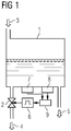
- Fig. 1 shows an example and schematically a tank emptying device according to the prior art.
- a fresh water tank 1 of a rail vehicle is shown, which has an inflow 3, a removal line 5 for supplying consumers such as sinks or kitchens and an outflow 4 for emptying the tank 1.
- the drain 4 is equipped with an emptying valve 2, which is electrically controllable and openable, which means that Content of tank 1 flows out into the open.
- a control device 9 receives sensor signals from an ultrasonic sensor 8 and a thermal switch 7.
- the ultrasonic sensor 8 determines the current fill level of the tank 1, the thermal switch 7 determines the temperature of the tank 1 or that of the water contained therein and gives a signal when the temperature falls below a certain level to the control device 9.
- this control device 9 determines the need for emptying, an empty tank, for example, no longer leading to an opening of the emptying valve 2 even when the temperature falls below a certain level.
- the control device 9 controls a timer 6, which opens the drain valve 2 for a certain period of time after this activation.
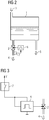
- Fig. 2 shows an example and schematically a tank emptying device.
- a tank emptying device according to the invention is shown, the tank 1 being essentially unchanged.
- a thermal switch 7 is provided, which is arranged at the drain 4. By mounting at this position, the thermal switch 7 can detect a trigger temperature at an early stage, since this point cools down much more quickly than the tank 1.
- the thermal switch 7 controls a timer 6 which opens the drain valve 2 for a certain period of time.
- An ultrasonic sensor 8 or any other fill level determination is not provided, since such is not necessary in a tank emptying device according to the invention.
- Fig. 3 shows an example and schematically a circuit of a tank emptying device. It is the electrical circuit of a tank emptying device according to the in Fig. 2 shown embodiment shown.
- the thermal switch 7 is shown in the open state, that is to say at a temperature higher than the triggering temperature.
- a voltage supply V is connected to a connection of the thermal switch 7. This can be taken directly from the vehicle battery.
- the output of the thermal switch 7 is led both to the control input and to the voltage supply input of the timing element 6.
- the timer 6 further comprises a ground connection. The output of the timer 6 is connected to the control connection of the drain valve 2.
- This circuit has no energy consumption in the rest position, as a result of which the energy stored in the vehicle battery is sufficient for a considerably longer operation and thus a considerably longer protective effect by the tank emptying device.
- the thermal switch 7 After the thermal switch 7 has been triggered and the outside temperature continues to be low, the current consumption of the timing element 6 remains as an electrical load on the vehicle battery. However, this is acceptable since the tank emptying device has already developed its protective effect.
Landscapes
- Engineering & Computer Science (AREA)
- Health & Medical Sciences (AREA)
- Public Health (AREA)
- Mechanical Engineering (AREA)
- Epidemiology (AREA)
- General Engineering & Computer Science (AREA)
- General Health & Medical Sciences (AREA)
- Hydrology & Water Resources (AREA)
- Life Sciences & Earth Sciences (AREA)
- Water Supply & Treatment (AREA)
- Transportation (AREA)
- Filling, Topping-Up Batteries (AREA)
- Air-Conditioning For Vehicles (AREA)
- Filling Or Discharging Of Gas Storage Vessels (AREA)
- Emergency Lowering Means (AREA)
- Medicines Containing Material From Animals Or Micro-Organisms (AREA)
Description
- Die Erfindung betrifft eine Tankentleerungseinrichtung für Frischwassertanks von Schienenfahrzeugen.
- Schienenfahrzeuge, insbesondere Passagierschienenfahrzeuge umfassen häufig Frischwassertanks zur Versorgung von Nasszellen, Küchen o.ä. Da diese Tanks Trinkwasser enthalten können sie bei längerem Stillstand des Fahrzeugs bei kalter Witterung einfrieren. Im Betrieb des Fahrzeugs besteht diese Gefahr nicht, da die Tanks im Allgemeinen im beheizten Innenraum, typischerweise in der Decke über der Nasszelle angeordnet sind. Friert der Inhalt eines Frischwassertanks, so kann das Fahrzeug nicht verwendet werden, da die sanitären Anlagen nicht betriebsbereit sind und muss in einer beheizten Halle erwärmt werden. Aufgrund der großen Wassermengen von ca. 300 Liter kann ein solcher Vorgang mehrere Tage dauern. Werden durch das frieren des Wassers Leitungen beschädigt, so müssen diese repariert werden. Zur Lösung dieses Problems sind Schienenfahrzeuge mit Frischwassertanks mit automatischen Entleerungseinrichtungen ausgestattet, welche bei unterschreiten einer bestimmten Temperatur des Tanks einen gefüllten Tank mittels eines Entleerungsventils ablassen. Diese Einrichtungen erfordern eine elektrische Energieversorgung, welche bei abgestellten Fahrzeugen durch eine Bordbatterie erfolgt. Es ist erforderlich, diese Entleerungseinrichtungen energiesparend auszuführen um den Schutz über längere Zeit (einige Wochen) aufrechterhalten zu können. Weiters soll die Entleerungseinrichtungen keine Fehlauslösungen vornehmen, da ein solches Fahrzeug (mit leerem Frischwassertank) nur sehr eingeschränkt verwendet werden kann bzw. die Wiederbefüllung nur in bestimmten Bahnhöfen erfolgen kann.
- Die
CH 201815 A - Der Erfindung liegt daher die Aufgabe zugrunde, eine Tankentleerungseinrichtung für Frischwassertanks von Schienenfahrzeugen anzugeben, welche Fehlauslösungen verhindert und stromsparend ist.
Die Aufgabe wird durch eine Tankentleerungseinrichtung mit den Merkmalen des Anspruchs 1 gelöst. Vorteilhafte Ausgestaltungen sind Gegenstand untergeordneter Ansprüche. - Dem Grundgedanken der Erfindung nach wird eine Tankentleerungseinrichtung für einen Frischwassertank eines Schienenfahrzeugs aufgebaut, wobei ein Thermoschalter mit dem Frischwasser thermisch gekoppelt ist und bei Unterschreiten einer bestimmten Temperatur des Tanks ein Zeitglied ansteuert, welches dadurch ein Entleerungsventil für einen bestimmte Zeitdauer öffnet, und wobei der Thermoschalter an einer Entleerungsleitung angeordnet ist.
Dadurch ist der Vorteil erzielbar, einen Schienenfahrzeugfrischwassertank bei Unterschreiten einer bestimmten Mindesttemperatur automatisch entleeren zu können. Erfindungsgemäß ist ein Thermoschalter vorgesehen, welcher so angeordnet ist, dass er die Temperatur des Frischwassers erfassen kann. Insbesondere ist es vorteilhaft, den Thermoschalter an jenen Teilen des Tanks, bzw. der Entleerungsanlage anzuordnen, welche bei Absinken der Außentemperatur zuerst durch einfrierendes Wasser verstopft werden. Die Entleerungsleitung führt das Wasser aus dem Wagenkasten ins Freie und ist der Umgebungstemperatur unmittelbar ausgesetzt, sodass der Thermoschalter an dieser Entleerungsleitung anzuordnen ist. Weiters würde eine vereiste Entleerungsleitung die Entleerung des Tanks ohnedies verhindern. - Eine Ausführungsform der Erfindung sieht vor, einen Thermoschalter mit einer Differenz zwischen dem Einschaltwert und dem Ausschaltwert von kleiner als 5 Kelvin einzusetzen. Konventionelle Thermoschalter weise wesentlich größere Schaltpunktdifferenzen auf, sodass die Entleerung bei wesentlich höheren Temperaturen als erforderlich eingeleitet wird. Konventionelle Thermoschalter weisen weder die erforderliche Schaltpunktgenauigkeit noch die erforderliche geringe Schaltpunkthysterese auf. Mit einem erfindungsgemäßen Thermoschalter (Präzisionsthermoschalter) kann die Auslösetemperatur deutlich näher an Null Grad Celsius dimensioniert werden, typischerweise auf einen Wert von 2 Grad Celsius. Ein solcher Thermoschalter weist eine Genauigkeit von einem Grad Celsius auf, sodass die Entleerung jedenfalls zwischen einem und drei Grad Celsius eingeleitet wird.
Konventionelle Thermostate hingegen müssen wegen ihrer Ungenauigkeiten auf wesentlich höhere Temperaturen eingestellt werden, wobei in besonders ungünstigen Fällen eine Entleerung schon bei ca. zehn Grad Celsius erfolgt. - Die Ausschaltschwelle kann aufgrund der hohen Präzision des erfindungsgemäßen Thermoschalters auf einen Wert von vier Grad Celsius bemessen werden, sodass der Thermoschalter bei einer Genauigkeit von einem Grad Celsius die Entleerung jedenfalls in einem Temperaturbereich zwischen drei und fünf Grad Celsius unterbricht. Ein solcher Thermoschalter weist eine Differenz zwischen dem Einschaltwert und dem Ausschaltwert von kleiner als 5 Kelvin auf.
- Gebräuchliche Tankentleerungseinrichtungen sind mit einer Einrichtung zur Füllstandsmessung ausgestattet, eine solche ist bei gegenständlicher Erfindung nicht erforderlich. Dadurch ist der Vorteil erzielbar, eine Reduktion des Energieverbrauchs der Tankentleerungseinrichtung erzielen zu können, da die Füllstandsmessung meist mit einem Ultraschallsensor erfolgt und ein solcher für den Betrieb elektrischer Energie bedarf.
Der aktuelle Füllstand des Frischwassertanks ist bei gegenständlicher Tankentleerungseinrichtung unwesentlich, da der Thermoschalter ein Zeitglied ansteuert, welches ein Entleerungsventil für einen bestimmten Zeitraum öffnet. Dieser Zeitraum ist auf das Volumen des Tanks und die Abflußmenge pro Zeit durch die Entleerungsleitung ab zustimmen, sodass der Tank jedenfalls entleert wird. Dabei ist das Zeitglied typischerweise bei gebräuchlichen Tanks auf eine Entleerungsdauer von 30 Minuten einzustellen. - Eine weitere Ausführungsform der Erfindung sieht vor, die Energieversorgung des Zeitglieds nicht kontinuierlich mit Spannung zu versorgen, sondern diese Energieversorgung ebenfalls aus dem vom Thermoschalter geschalteten Signal zu entnehmen. Solcherart kann der Energieverbrauch der Tankentleerungseinrichtung während der Zeit bis zur Auslösung (Entleerungsbeginn) auf Null reduziert werden. Ein Thermoschalter weist keinen Energieverbrauch auf, das von ihm geschaltete Zeitglied verbraucht nur während der Entleerung Energie, ebenso das von dem Zeitglied angesteuerte Entleerungsventil. Solcherart kann eine Tankentleerungseinrichtung aufgebaut werden, die die Fahrzeugstromversorgung nur geringstmöglich belastet und dadurch die längstmögliche Einsatzdauer der Tankentleerungseinrichtung bei einer bestimmten Batteriekapazität gewährleistet.
- Es zeigen beispielhaft:
- Fig.1
- Tankentleerungseinrichtung gemäß dem Stand der Technik.
- Fig.2
- Tankentleerungseinrichtung.
- Fig.3
- Schaltung einer Tankentleerungseinrichtung.
-
Fig.1 zeigt beispielhaft und schematisch eine Tankentleerungseinrichtung gemäß dem Stand der Technik. Es ist ein Frischwassertank 1 eines Schienenfahrzeugs dargestellt, welcher einen Zufluß 3, eine Entnahmeleitung 5 zur Versorgung von Verbrauchern wie Waschbecken oder Küchen und einen Abfluß 4 zur Entleerung des Tanks 1 aufweist. Der Abfluß 4 ist mit einem Entleerungsventil 2 ausgestattet, welches elektrisch ansteuerbar und öffenbar ist wodurch der Inhalt des Tanks 1 in das Freie abfließt. Eine Steuereinrichtung 9 empfängt Sensorsignale von einem Ultraschallsensor 8 und einem Thermoschalter 7. Der Ultraschallsensor 8 ermittelt den aktuellen Füllstand des Tanks 1, der Thermoschalter 7 bestimmt die Temperatur des Tanks 1 bzw. die des darin enthaltenen Wassers und gibt bei Unterschreiten einer bestimmten Temperatur ein Signal an die Steuereinrichtung 9 ab. Diese Steuereinrichtung 9 bestimmt aus den Signalen des Thermoschalters 7 und des Ultraschallsensors die Notwendigkeit einer Entleerung, wobei beispielsweise ein bereits leerer Tank auch bei Unterschreiten einer bestimmten Temperatur nicht mehr zu einer Öffnung des Entleerungsventils 2 führt. Die Steuereinrichtung 9 steuert ein Zeitglied 6 an, welches nach dieser Ansteuerung das Entleerungsventil 2 für einen bestimmten Zeitraum öffnet. -
Fig.2 zeigt beispielhaft und schematisch eine Tankentleerungseinrichtung. Es ist eine erfindungsgemäße Tankentleerungseinrichtung dargestellt, wobei der Tank 1 im Wesentlichen unverändert ist. Es ist ein Thermoschalter 7 vorgesehen, welcher an dem Abfluß 4 angeordnet ist. Durch die Montage an dieser Position kann der Thermoschalter 7 frühzeitig eine Auslösetemperatur erfassen, da diese Stelle wesentlich rascher auskühlt als der Tank 1. Der Thermoschalter 7 steuert unmittelbar ein Zeitglied 6 an, welches für einen bestimmten Zeitraum das Entleerungsventil 2 öffnet. Ein Ultraschallsensor 8 oder eine sonstige Füllstandsermittlung ist nicht vorgesehen, da eine solche bei einer erfindungsgemäßen Tankentleerungseinrichtung nicht erforderlich ist. -
Fig.3 zeigt beispielhaft und schematisch eine Schaltung einer Tankentleerungseinrichtung. Es ist die elektrische Schaltung einer Tankentleerungseinrichtung gemäß dem inFig.2 gezeigten Ausführungsbeispiel dargestellt. Der Thermoschalter 7 ist in geöffnetem Zustand, also bei einer höheren Temperatur als der Auslösetemperatur gezeigt. Eine Spannungsversorgung V ist an einen Anschluß des Thermoschalters 7 geführt. Diese kann unmittelbar von der Fahrzeugbatterie entnommen werden. Der Ausgang des Thermoschalters 7 ist sowohl an den Steuereingang als auch an den Spannungsversorgungseingang des Zeitgliedes 6 geführt. Das Zeitglied 6 umfasst weiters einen Masseanschluß. Der Ausgang des Zeitgliedes 6 ist an den Steueranschluß des Entleerungsventils 2 geführt. Diese Schaltung weist in Ruhestellung keinen Energieverbrauch auf, wodurch die in der Fahrzeugbatterie gespeicherte Energie für einen wesentlich längeren Betrieb und somit eine wesentlich längere Schutzwirkung durch die Tankentleerungseinrichtung ausreicht. Nach einer Auslösung des Thermoschalters 7 und weiterhin niedriger Aussentemperatur verbleibt der Stromverbrauch des Zeitglieds 6 als elektrische Last an der Fahrzeugbatterie. Dies ist jedoch akzeptabel, da dazu die Tankentleerungseinrichtung bereits ihre Schutzwirkung entfaltet hat. -
- 1
- Tank
- 2
- Entleerungsventil
- 3
- Zufluß
- 4
- Abfluß, Entleerungsleitung
- 5
- Entnahmeleitung
- 6
- Zeitglied
- 7
- Thermoschalter
- 8
- Ultraschallsensor
- 9
- Steuereinrichtung
- V
- Spannungsversorgung
Claims (4)
- Tankentleerungseinrichtung für einen Frischwassertank (1) eines Schienenfahrzeugs, wobei ein Thermoschalter (7) mit dem Frischwasser thermisch gekoppelt ist, wobei der Thermoschalter (7) an einer Entleerungsleitung (4) angeordnet ist und bei Unterschreiten einer bestimmten Temperatur des Tanks (1) ein Zeitglied (6) ansteuert, welches dadurch ein Entleerungsventil (2) für einen bestimmte Zeitdauer öffnet, dadurch gekennzeichnet, dass diese Zeitdauer auf das Volumen des Tanks und die Abflußmenge pro Zeit durch die Entleerungsleitung so bemessen ist, dass der Tank jedenfalls entleert wird.
- Tankentleerungseinrichtung nach Anspruch 1, dadurch gekennzeichnet, dass der Thermoschalter (7) eine Differenz zwischen dem Einschaltwert und dem Ausschaltwert von kleiner als 5 Kelvin aufweist.
- Tankentleerungseinrichtung nach einem der Ansprüche 1 oder 2, dadurch gekennzeichnet, dass eine von dem Thermoschalter (7) an das Zeitglied (6) geleitete elektrische Spannung sowohl an den Energieversorgungsanschluß des Zeitglieds (6) als auch den Steuereingang des Zeitglieds (6) geführt ist.
- Tankentleerungseinrichtung nach einem der Ansprüche 1 bis 3, dadurch gekennzeichnet, dass das Zeitglied (6) bei einer Auslösung durch den Thermoschalter (7) ein Entleerungsventil (2) für maximal 45 Minuten öffnet.
Applications Claiming Priority (2)
| Application Number | Priority Date | Filing Date | Title |
|---|---|---|---|
| ATA50433/2012A AT513557B1 (de) | 2012-10-08 | 2012-10-08 | Tankentleerungseinrichtung |
| PCT/EP2013/070502 WO2014056768A1 (de) | 2012-10-08 | 2013-10-02 | Tankentleerungseinrichtung |
Publications (2)
| Publication Number | Publication Date |
|---|---|
| EP2904156A1 EP2904156A1 (de) | 2015-08-12 |
| EP2904156B1 true EP2904156B1 (de) | 2020-03-11 |
Family
ID=49322347
Family Applications (1)
| Application Number | Title | Priority Date | Filing Date |
|---|---|---|---|
| EP13774115.3A Active EP2904156B1 (de) | 2012-10-08 | 2013-10-02 | Tankentleerungseinrichtung |
Country Status (6)
| Country | Link |
|---|---|
| US (1) | US20150267833A1 (de) |
| EP (1) | EP2904156B1 (de) |
| CN (1) | CN104685135A (de) |
| AT (1) | AT513557B1 (de) |
| RU (1) | RU2650395C2 (de) |
| WO (1) | WO2014056768A1 (de) |
Families Citing this family (5)
| Publication number | Priority date | Publication date | Assignee | Title |
|---|---|---|---|---|
| DE102015205825B4 (de) | 2015-03-31 | 2021-09-23 | Siemens Mobility GmbH | Verfahren zur Frostentleerung eines Frischwasserbehälters für ein Schienenfahrzeug des Personenverkehrs und Schienenfahrzeug des Personenverkehrs mit einer Frostentleerungseinrichtung |
| DE102016203385A1 (de) * | 2016-03-02 | 2017-09-07 | Siemens Aktiengesellschaft | Sanitäreinrichtung für ein Fahrzeug |
| DE202017105462U1 (de) * | 2017-09-08 | 2018-12-14 | Vogelsang Gmbh & Co. Kg | Abschaltvorrichtung für die Befüllung von Wassertanks von Personenzugwaggons |
| CN112061151B (zh) * | 2020-09-23 | 2025-08-08 | 中车西安车辆有限公司 | 一种具有加热功能的大容积铁路罐车 |
| DE102023209308B4 (de) | 2023-09-22 | 2025-04-24 | Siemens Mobility GmbH | Zustandsbasierte Frostentleerung für ein Schienenfahrzeug |
Family Cites Families (19)
| Publication number | Priority date | Publication date | Assignee | Title |
|---|---|---|---|---|
| NL46777C (de) * | 1936-12-24 | |||
| US3812872A (en) * | 1972-06-22 | 1974-05-28 | Raypak Inc | System to prevent freezing of heating units such as boilers |
| US4216554A (en) * | 1979-02-12 | 1980-08-12 | Gard, Inc. | Automatic freeze-proof drain system |
| GB2074640B (en) * | 1980-04-25 | 1983-11-02 | Fantom T | Control device for a water fed installation |
| GB2117436A (en) * | 1982-03-26 | 1983-10-12 | Paul Ferron | Pipework frost protection system |
| US4635668A (en) * | 1985-09-13 | 1987-01-13 | Netter Aaron J | Automatic water line freeze control |
| US4657038A (en) * | 1986-06-09 | 1987-04-14 | Lyons Kevin D | Apparatus for preventing water pipe freeze-up |
| GB8703123D0 (en) * | 1987-02-11 | 1987-03-18 | Fermin F C | Protect system against malfunctioning |
| US5240179A (en) * | 1991-11-22 | 1993-08-31 | Drinkwater Don L | Anti-freeze assist apparatus |
| JPH07240136A (ja) * | 1994-02-25 | 1995-09-12 | Temuko Kk | 温度スイッチ |
| JPH0820976A (ja) * | 1994-07-07 | 1996-01-23 | S N Seiki:Kk | 水道凍結防止ヒータ用節電ユニット |
| US6125873A (en) * | 1998-10-23 | 2000-10-03 | Brown; Daniel H. | Temperature sensing flow control device |
| US6892751B2 (en) * | 2002-02-28 | 2005-05-17 | Mark Sanders | System and method for protecting a building |
| DE202005001105U1 (de) * | 2005-01-25 | 2005-04-21 | Simmler, Franz | Vorrichtung zum Verhindern und Wiederöffnen des Einfrierens von Wasserleitungen und Ventilen |
| CN101581315B (zh) * | 2008-05-16 | 2012-07-04 | 南车青岛四方机车车辆股份有限公司 | 轨道车辆给水系统中的水泵控制方法及控制系统 |
| CN101638905A (zh) * | 2009-06-02 | 2010-02-03 | 刘德鹏 | 手动上下水管道排空防冻装置 |
| LT2305530T (lt) * | 2009-10-02 | 2017-03-27 | Alstom Transport Technologies | Būdas transporto priemonės gėlo vandens sistemai apsaugoti nuo užšalimo |
| CN202012100U (zh) * | 2011-04-14 | 2011-10-19 | 朱建英 | 一种防冻水管 |
| US8944086B2 (en) * | 2012-07-02 | 2015-02-03 | James F. Park | Plumbing freeze protection system |
-
2012
- 2012-10-08 AT ATA50433/2012A patent/AT513557B1/de not_active IP Right Cessation
-
2013
- 2013-10-02 EP EP13774115.3A patent/EP2904156B1/de active Active
- 2013-10-02 WO PCT/EP2013/070502 patent/WO2014056768A1/de not_active Ceased
- 2013-10-02 US US14/434,170 patent/US20150267833A1/en not_active Abandoned
- 2013-10-02 CN CN201380052518.3A patent/CN104685135A/zh active Pending
- 2013-10-02 RU RU2015112720A patent/RU2650395C2/ru active
Non-Patent Citations (1)
| Title |
|---|
| None * |
Also Published As
| Publication number | Publication date |
|---|---|
| AT513557B1 (de) | 2014-07-15 |
| CN104685135A (zh) | 2015-06-03 |
| AT513557A1 (de) | 2014-05-15 |
| EP2904156A1 (de) | 2015-08-12 |
| US20150267833A1 (en) | 2015-09-24 |
| WO2014056768A1 (de) | 2014-04-17 |
| RU2015112720A (ru) | 2016-11-27 |
| RU2650395C2 (ru) | 2018-04-11 |
Similar Documents
| Publication | Publication Date | Title |
|---|---|---|
| AT513557B1 (de) | Tankentleerungseinrichtung | |
| EP3055608B1 (de) | Sicherheitseinrichtung eines druckgastanks insbesondere eines kraftfahrzeugs | |
| EP2305530B1 (de) | Verfahren zum Schutz des Frischwassersystems eines Fahrzeugs vor Frost | |
| DE102010039875A1 (de) | Verfahren und Vorrichtung zum Betreiben eines Starters eines Fahrzeugs | |
| DE102019000378A1 (de) | Warmwassergerät und Verfahren zum Betreiben eines Warmwassergerätes | |
| EP3820733B1 (de) | Mehrspannungsbatterievorrichtung und bordnetz für ein kraftfahrzeug | |
| DE102011006951A1 (de) | Verfahren zur Regelung eines Kältegeräts | |
| DE102019000389A1 (de) | Warmwassergerät und Verfahren zum Betreiben eines Warmwassergerätes | |
| DE102012019607A1 (de) | Energiespeicheranordnung für ein Bordnetz eines Kraftfahrzeugs, Kraftfahrzeug und Verfahren zum Betrieb einer Energiespeicheranordnung | |
| DE102007039557A1 (de) | Verfahren und Vorrichtung zum Bestimmen eines Schaltpunkts für eine Füllstandsregulierung | |
| DE102014203396A1 (de) | Druckluftanlage und Verfahren zum Betreiben einer Druckluftanlage | |
| WO2014090470A1 (de) | Schutzschaltung | |
| DE102018210979B4 (de) | Mehrspannungsbatterievorrichtung und Mehrspannungsbordnetz für ein Kraftfahrzeug | |
| DE102017222544B4 (de) | Mehrspannungsbatterievorrichtung und Bordnetz für ein Kraftfahrzeug | |
| DE1513280A1 (de) | Vorrichtung zur UEberlastungssicherung von Elektromotoren | |
| DE10156389A1 (de) | Starteinrichtung für Brennkraftmaschinen | |
| DE102015217234A1 (de) | Schaltungsanordnung zum Versorgen einer elektrischen Komponente | |
| DE102014117753B4 (de) | Kontaktschutz-Schnittstelle für Starthilfe | |
| DE102014201196A1 (de) | Verfahren zum Betreiben eines Batteriemanagementsystems und Batteriemanagementsystem | |
| CH232806A (de) | Elektrische Anlage für Fahrzeuge, insbesondere für Kraftfahrzeuge. | |
| DE102017112065A1 (de) | Sanitäranlage | |
| DE3231343A1 (de) | Verfahren zur regelung einer heizungsanlage | |
| DE102012218678A1 (de) | Schaltung zur Steuerung der Energieversorgung eines elektrischen Geräts sowie elektrisches Gerät mit einer Schaltung | |
| DE1538355C (de) | Schaltungsanordnung zur Überwachung eines elektrischen Motorpumpenaggregats | |
| DE102008063019A1 (de) | Einrichtung und Verfahren für eine flüssigkeitsführende Anlage |
Legal Events
| Date | Code | Title | Description |
|---|---|---|---|
| PUAI | Public reference made under article 153(3) epc to a published international application that has entered the european phase |
Free format text: ORIGINAL CODE: 0009012 |
|
| 17P | Request for examination filed |
Effective date: 20150213 |
|
| AK | Designated contracting states |
Kind code of ref document: A1 Designated state(s): AL AT BE BG CH CY CZ DE DK EE ES FI FR GB GR HR HU IE IS IT LI LT LU LV MC MK MT NL NO PL PT RO RS SE SI SK SM TR |
|
| AX | Request for extension of the european patent |
Extension state: BA ME |
|
| DAX | Request for extension of the european patent (deleted) | ||
| RAP1 | Party data changed (applicant data changed or rights of an application transferred) |
Owner name: SIEMENS MOBILITY GMBH |
|
| GRAP | Despatch of communication of intention to grant a patent |
Free format text: ORIGINAL CODE: EPIDOSNIGR1 |
|
| STAA | Information on the status of an ep patent application or granted ep patent |
Free format text: STATUS: GRANT OF PATENT IS INTENDED |
|
| INTG | Intention to grant announced |
Effective date: 20191002 |
|
| RAP1 | Party data changed (applicant data changed or rights of an application transferred) |
Owner name: SIEMENS MOBILITY AUSTRIA GMBH |
|
| GRAS | Grant fee paid |
Free format text: ORIGINAL CODE: EPIDOSNIGR3 |
|
| GRAA | (expected) grant |
Free format text: ORIGINAL CODE: 0009210 |
|
| STAA | Information on the status of an ep patent application or granted ep patent |
Free format text: STATUS: THE PATENT HAS BEEN GRANTED |
|
| AK | Designated contracting states |
Kind code of ref document: B1 Designated state(s): AL AT BE BG CH CY CZ DE DK EE ES FI FR GB GR HR HU IE IS IT LI LT LU LV MC MK MT NL NO PL PT RO RS SE SI SK SM TR |
|
| REG | Reference to a national code |
Ref country code: GB Ref legal event code: FG4D Free format text: NOT ENGLISH |
|
| REG | Reference to a national code |
Ref country code: CH Ref legal event code: EP |
|
| REG | Reference to a national code |
Ref country code: AT Ref legal event code: REF Ref document number: 1243293 Country of ref document: AT Kind code of ref document: T Effective date: 20200315 |
|
| REG | Reference to a national code |
Ref country code: IE Ref legal event code: FG4D Free format text: LANGUAGE OF EP DOCUMENT: GERMAN |
|
| REG | Reference to a national code |
Ref country code: DE Ref legal event code: R096 Ref document number: 502013014435 Country of ref document: DE |
|
| PG25 | Lapsed in a contracting state [announced via postgrant information from national office to epo] |
Ref country code: NO Free format text: LAPSE BECAUSE OF FAILURE TO SUBMIT A TRANSLATION OF THE DESCRIPTION OR TO PAY THE FEE WITHIN THE PRESCRIBED TIME-LIMIT Effective date: 20200611 Ref country code: FI Free format text: LAPSE BECAUSE OF FAILURE TO SUBMIT A TRANSLATION OF THE DESCRIPTION OR TO PAY THE FEE WITHIN THE PRESCRIBED TIME-LIMIT Effective date: 20200311 Ref country code: RS Free format text: LAPSE BECAUSE OF FAILURE TO SUBMIT A TRANSLATION OF THE DESCRIPTION OR TO PAY THE FEE WITHIN THE PRESCRIBED TIME-LIMIT Effective date: 20200311 |
|
| REG | Reference to a national code |
Ref country code: NL Ref legal event code: MP Effective date: 20200311 |
|
| PG25 | Lapsed in a contracting state [announced via postgrant information from national office to epo] |
Ref country code: SE Free format text: LAPSE BECAUSE OF FAILURE TO SUBMIT A TRANSLATION OF THE DESCRIPTION OR TO PAY THE FEE WITHIN THE PRESCRIBED TIME-LIMIT Effective date: 20200311 Ref country code: LV Free format text: LAPSE BECAUSE OF FAILURE TO SUBMIT A TRANSLATION OF THE DESCRIPTION OR TO PAY THE FEE WITHIN THE PRESCRIBED TIME-LIMIT Effective date: 20200311 Ref country code: GR Free format text: LAPSE BECAUSE OF FAILURE TO SUBMIT A TRANSLATION OF THE DESCRIPTION OR TO PAY THE FEE WITHIN THE PRESCRIBED TIME-LIMIT Effective date: 20200612 Ref country code: HR Free format text: LAPSE BECAUSE OF FAILURE TO SUBMIT A TRANSLATION OF THE DESCRIPTION OR TO PAY THE FEE WITHIN THE PRESCRIBED TIME-LIMIT Effective date: 20200311 Ref country code: BG Free format text: LAPSE BECAUSE OF FAILURE TO SUBMIT A TRANSLATION OF THE DESCRIPTION OR TO PAY THE FEE WITHIN THE PRESCRIBED TIME-LIMIT Effective date: 20200611 |
|
| REG | Reference to a national code |
Ref country code: LT Ref legal event code: MG4D |
|
| PG25 | Lapsed in a contracting state [announced via postgrant information from national office to epo] |
Ref country code: NL Free format text: LAPSE BECAUSE OF FAILURE TO SUBMIT A TRANSLATION OF THE DESCRIPTION OR TO PAY THE FEE WITHIN THE PRESCRIBED TIME-LIMIT Effective date: 20200311 |
|
| PG25 | Lapsed in a contracting state [announced via postgrant information from national office to epo] |
Ref country code: RO Free format text: LAPSE BECAUSE OF FAILURE TO SUBMIT A TRANSLATION OF THE DESCRIPTION OR TO PAY THE FEE WITHIN THE PRESCRIBED TIME-LIMIT Effective date: 20200311 Ref country code: PT Free format text: LAPSE BECAUSE OF FAILURE TO SUBMIT A TRANSLATION OF THE DESCRIPTION OR TO PAY THE FEE WITHIN THE PRESCRIBED TIME-LIMIT Effective date: 20200805 Ref country code: SK Free format text: LAPSE BECAUSE OF FAILURE TO SUBMIT A TRANSLATION OF THE DESCRIPTION OR TO PAY THE FEE WITHIN THE PRESCRIBED TIME-LIMIT Effective date: 20200311 Ref country code: IS Free format text: LAPSE BECAUSE OF FAILURE TO SUBMIT A TRANSLATION OF THE DESCRIPTION OR TO PAY THE FEE WITHIN THE PRESCRIBED TIME-LIMIT Effective date: 20200711 Ref country code: SM Free format text: LAPSE BECAUSE OF FAILURE TO SUBMIT A TRANSLATION OF THE DESCRIPTION OR TO PAY THE FEE WITHIN THE PRESCRIBED TIME-LIMIT Effective date: 20200311 Ref country code: EE Free format text: LAPSE BECAUSE OF FAILURE TO SUBMIT A TRANSLATION OF THE DESCRIPTION OR TO PAY THE FEE WITHIN THE PRESCRIBED TIME-LIMIT Effective date: 20200311 Ref country code: LT Free format text: LAPSE BECAUSE OF FAILURE TO SUBMIT A TRANSLATION OF THE DESCRIPTION OR TO PAY THE FEE WITHIN THE PRESCRIBED TIME-LIMIT Effective date: 20200311 |
|
| REG | Reference to a national code |
Ref country code: DE Ref legal event code: R097 Ref document number: 502013014435 Country of ref document: DE |
|
| PLBE | No opposition filed within time limit |
Free format text: ORIGINAL CODE: 0009261 |
|
| STAA | Information on the status of an ep patent application or granted ep patent |
Free format text: STATUS: NO OPPOSITION FILED WITHIN TIME LIMIT |
|
| PG25 | Lapsed in a contracting state [announced via postgrant information from national office to epo] |
Ref country code: ES Free format text: LAPSE BECAUSE OF FAILURE TO SUBMIT A TRANSLATION OF THE DESCRIPTION OR TO PAY THE FEE WITHIN THE PRESCRIBED TIME-LIMIT Effective date: 20200311 Ref country code: DK Free format text: LAPSE BECAUSE OF FAILURE TO SUBMIT A TRANSLATION OF THE DESCRIPTION OR TO PAY THE FEE WITHIN THE PRESCRIBED TIME-LIMIT Effective date: 20200311 |
|
| 26N | No opposition filed |
Effective date: 20201214 |
|
| PG25 | Lapsed in a contracting state [announced via postgrant information from national office to epo] |
Ref country code: SI Free format text: LAPSE BECAUSE OF FAILURE TO SUBMIT A TRANSLATION OF THE DESCRIPTION OR TO PAY THE FEE WITHIN THE PRESCRIBED TIME-LIMIT Effective date: 20200311 Ref country code: PL Free format text: LAPSE BECAUSE OF FAILURE TO SUBMIT A TRANSLATION OF THE DESCRIPTION OR TO PAY THE FEE WITHIN THE PRESCRIBED TIME-LIMIT Effective date: 20200311 |
|
| REG | Reference to a national code |
Ref country code: CH Ref legal event code: NV Representative=s name: SIEMENS SCHWEIZ AG, CH |
|
| REG | Reference to a national code |
Ref country code: CH Ref legal event code: PL |
|
| GBPC | Gb: european patent ceased through non-payment of renewal fee |
Effective date: 20201002 |
|
| PG25 | Lapsed in a contracting state [announced via postgrant information from national office to epo] |
Ref country code: LU Free format text: LAPSE BECAUSE OF NON-PAYMENT OF DUE FEES Effective date: 20201002 Ref country code: MC Free format text: LAPSE BECAUSE OF FAILURE TO SUBMIT A TRANSLATION OF THE DESCRIPTION OR TO PAY THE FEE WITHIN THE PRESCRIBED TIME-LIMIT Effective date: 20200311 |
|
| REG | Reference to a national code |
Ref country code: BE Ref legal event code: MM Effective date: 20201031 |
|
| PG25 | Lapsed in a contracting state [announced via postgrant information from national office to epo] |
Ref country code: BE Free format text: LAPSE BECAUSE OF NON-PAYMENT OF DUE FEES Effective date: 20201031 Ref country code: CH Free format text: LAPSE BECAUSE OF NON-PAYMENT OF DUE FEES Effective date: 20201031 Ref country code: LI Free format text: LAPSE BECAUSE OF NON-PAYMENT OF DUE FEES Effective date: 20201031 Ref country code: GB Free format text: LAPSE BECAUSE OF NON-PAYMENT OF DUE FEES Effective date: 20201002 |
|
| PG25 | Lapsed in a contracting state [announced via postgrant information from national office to epo] |
Ref country code: IE Free format text: LAPSE BECAUSE OF NON-PAYMENT OF DUE FEES Effective date: 20201002 |
|
| PG25 | Lapsed in a contracting state [announced via postgrant information from national office to epo] |
Ref country code: TR Free format text: LAPSE BECAUSE OF FAILURE TO SUBMIT A TRANSLATION OF THE DESCRIPTION OR TO PAY THE FEE WITHIN THE PRESCRIBED TIME-LIMIT Effective date: 20200311 Ref country code: MT Free format text: LAPSE BECAUSE OF FAILURE TO SUBMIT A TRANSLATION OF THE DESCRIPTION OR TO PAY THE FEE WITHIN THE PRESCRIBED TIME-LIMIT Effective date: 20200311 Ref country code: CY Free format text: LAPSE BECAUSE OF FAILURE TO SUBMIT A TRANSLATION OF THE DESCRIPTION OR TO PAY THE FEE WITHIN THE PRESCRIBED TIME-LIMIT Effective date: 20200311 |
|
| PG25 | Lapsed in a contracting state [announced via postgrant information from national office to epo] |
Ref country code: MK Free format text: LAPSE BECAUSE OF FAILURE TO SUBMIT A TRANSLATION OF THE DESCRIPTION OR TO PAY THE FEE WITHIN THE PRESCRIBED TIME-LIMIT Effective date: 20200311 Ref country code: AL Free format text: LAPSE BECAUSE OF FAILURE TO SUBMIT A TRANSLATION OF THE DESCRIPTION OR TO PAY THE FEE WITHIN THE PRESCRIBED TIME-LIMIT Effective date: 20200311 |
|
| PGFP | Annual fee paid to national office [announced via postgrant information from national office to epo] |
Ref country code: CZ Payment date: 20250925 Year of fee payment: 13 |
|
| PGFP | Annual fee paid to national office [announced via postgrant information from national office to epo] |
Ref country code: AT Payment date: 20250905 Year of fee payment: 13 |
|
| PGFP | Annual fee paid to national office [announced via postgrant information from national office to epo] |
Ref country code: IT Payment date: 20251027 Year of fee payment: 13 |
|
| PGFP | Annual fee paid to national office [announced via postgrant information from national office to epo] |
Ref country code: FR Payment date: 20251020 Year of fee payment: 13 |
|
| PGFP | Annual fee paid to national office [announced via postgrant information from national office to epo] |
Ref country code: DE Payment date: 20251219 Year of fee payment: 13 |