EP2903738B1 - Procédé microfluidique de traitement et d'analyse d'une solution contenant un matériel biologique, et circuit microfluidique correspondant - Google Patents
Procédé microfluidique de traitement et d'analyse d'une solution contenant un matériel biologique, et circuit microfluidique correspondant Download PDFInfo
- Publication number
- EP2903738B1 EP2903738B1 EP13774166.6A EP13774166A EP2903738B1 EP 2903738 B1 EP2903738 B1 EP 2903738B1 EP 13774166 A EP13774166 A EP 13774166A EP 2903738 B1 EP2903738 B1 EP 2903738B1
- Authority
- EP
- European Patent Office
- Prior art keywords
- drops
- microfluidic
- microfluidic circuit
- solution
- circuit
- Prior art date
- Legal status (The legal status is an assumption and is not a legal conclusion. Google has not performed a legal analysis and makes no representation as to the accuracy of the status listed.)
- Active
Links
Images


Classifications
-
- C—CHEMISTRY; METALLURGY
- C12—BIOCHEMISTRY; BEER; SPIRITS; WINE; VINEGAR; MICROBIOLOGY; ENZYMOLOGY; MUTATION OR GENETIC ENGINEERING
- C12Q—MEASURING OR TESTING PROCESSES INVOLVING ENZYMES, NUCLEIC ACIDS OR MICROORGANISMS; COMPOSITIONS OR TEST PAPERS THEREFOR; PROCESSES OF PREPARING SUCH COMPOSITIONS; CONDITION-RESPONSIVE CONTROL IN MICROBIOLOGICAL OR ENZYMOLOGICAL PROCESSES
- C12Q1/00—Measuring or testing processes involving enzymes, nucleic acids or microorganisms; Compositions therefor; Processes of preparing such compositions
- C12Q1/68—Measuring or testing processes involving enzymes, nucleic acids or microorganisms; Compositions therefor; Processes of preparing such compositions involving nucleic acids
- C12Q1/6844—Nucleic acid amplification reactions
- C12Q1/686—Polymerase chain reaction [PCR]
-
- B—PERFORMING OPERATIONS; TRANSPORTING
- B01—PHYSICAL OR CHEMICAL PROCESSES OR APPARATUS IN GENERAL
- B01L—CHEMICAL OR PHYSICAL LABORATORY APPARATUS FOR GENERAL USE
- B01L3/00—Containers or dishes for laboratory use, e.g. laboratory glassware; Droppers
- B01L3/50—Containers for the purpose of retaining a material to be analysed, e.g. test tubes
- B01L3/502—Containers for the purpose of retaining a material to be analysed, e.g. test tubes with fluid transport, e.g. in multi-compartment structures
- B01L3/5027—Containers for the purpose of retaining a material to be analysed, e.g. test tubes with fluid transport, e.g. in multi-compartment structures by integrated microfluidic structures, i.e. dimensions of channels and chambers are such that surface tension forces are important, e.g. lab-on-a-chip
- B01L3/50273—Containers for the purpose of retaining a material to be analysed, e.g. test tubes with fluid transport, e.g. in multi-compartment structures by integrated microfluidic structures, i.e. dimensions of channels and chambers are such that surface tension forces are important, e.g. lab-on-a-chip characterised by the means or forces applied to move the fluids
-
- B—PERFORMING OPERATIONS; TRANSPORTING
- B01—PHYSICAL OR CHEMICAL PROCESSES OR APPARATUS IN GENERAL
- B01L—CHEMICAL OR PHYSICAL LABORATORY APPARATUS FOR GENERAL USE
- B01L3/00—Containers or dishes for laboratory use, e.g. laboratory glassware; Droppers
- B01L3/50—Containers for the purpose of retaining a material to be analysed, e.g. test tubes
- B01L3/502—Containers for the purpose of retaining a material to be analysed, e.g. test tubes with fluid transport, e.g. in multi-compartment structures
- B01L3/5027—Containers for the purpose of retaining a material to be analysed, e.g. test tubes with fluid transport, e.g. in multi-compartment structures by integrated microfluidic structures, i.e. dimensions of channels and chambers are such that surface tension forces are important, e.g. lab-on-a-chip
- B01L3/502761—Containers for the purpose of retaining a material to be analysed, e.g. test tubes with fluid transport, e.g. in multi-compartment structures by integrated microfluidic structures, i.e. dimensions of channels and chambers are such that surface tension forces are important, e.g. lab-on-a-chip specially adapted for handling suspended solids or molecules independently from the bulk fluid flow, e.g. for trapping or sorting beads or physically stretching molecules
-
- B—PERFORMING OPERATIONS; TRANSPORTING
- B01—PHYSICAL OR CHEMICAL PROCESSES OR APPARATUS IN GENERAL
- B01L—CHEMICAL OR PHYSICAL LABORATORY APPARATUS FOR GENERAL USE
- B01L3/00—Containers or dishes for laboratory use, e.g. laboratory glassware; Droppers
- B01L3/50—Containers for the purpose of retaining a material to be analysed, e.g. test tubes
- B01L3/502—Containers for the purpose of retaining a material to be analysed, e.g. test tubes with fluid transport, e.g. in multi-compartment structures
- B01L3/5027—Containers for the purpose of retaining a material to be analysed, e.g. test tubes with fluid transport, e.g. in multi-compartment structures by integrated microfluidic structures, i.e. dimensions of channels and chambers are such that surface tension forces are important, e.g. lab-on-a-chip
- B01L3/502769—Containers for the purpose of retaining a material to be analysed, e.g. test tubes with fluid transport, e.g. in multi-compartment structures by integrated microfluidic structures, i.e. dimensions of channels and chambers are such that surface tension forces are important, e.g. lab-on-a-chip characterised by multiphase flow arrangements
- B01L3/502784—Containers for the purpose of retaining a material to be analysed, e.g. test tubes with fluid transport, e.g. in multi-compartment structures by integrated microfluidic structures, i.e. dimensions of channels and chambers are such that surface tension forces are important, e.g. lab-on-a-chip characterised by multiphase flow arrangements specially adapted for droplet or plug flow, e.g. digital microfluidics
- B01L3/502792—Containers for the purpose of retaining a material to be analysed, e.g. test tubes with fluid transport, e.g. in multi-compartment structures by integrated microfluidic structures, i.e. dimensions of channels and chambers are such that surface tension forces are important, e.g. lab-on-a-chip characterised by multiphase flow arrangements specially adapted for droplet or plug flow, e.g. digital microfluidics for moving individual droplets on a plate, e.g. by locally altering surface tension
-
- B—PERFORMING OPERATIONS; TRANSPORTING
- B01—PHYSICAL OR CHEMICAL PROCESSES OR APPARATUS IN GENERAL
- B01L—CHEMICAL OR PHYSICAL LABORATORY APPARATUS FOR GENERAL USE
- B01L7/00—Heating or cooling apparatus; Heat insulating devices
- B01L7/52—Heating or cooling apparatus; Heat insulating devices with provision for submitting samples to a predetermined sequence of different temperatures, e.g. for treating nucleic acid samples
-
- B—PERFORMING OPERATIONS; TRANSPORTING
- B01—PHYSICAL OR CHEMICAL PROCESSES OR APPARATUS IN GENERAL
- B01L—CHEMICAL OR PHYSICAL LABORATORY APPARATUS FOR GENERAL USE
- B01L2200/00—Solutions for specific problems relating to chemical or physical laboratory apparatus
- B01L2200/06—Fluid handling related problems
- B01L2200/0642—Filling fluids into wells by specific techniques
-
- B—PERFORMING OPERATIONS; TRANSPORTING
- B01—PHYSICAL OR CHEMICAL PROCESSES OR APPARATUS IN GENERAL
- B01L—CHEMICAL OR PHYSICAL LABORATORY APPARATUS FOR GENERAL USE
- B01L2200/00—Solutions for specific problems relating to chemical or physical laboratory apparatus
- B01L2200/06—Fluid handling related problems
- B01L2200/0647—Handling flowable solids, e.g. microscopic beads, cells, particles
- B01L2200/0652—Sorting or classification of particles or molecules
-
- B—PERFORMING OPERATIONS; TRANSPORTING
- B01—PHYSICAL OR CHEMICAL PROCESSES OR APPARATUS IN GENERAL
- B01L—CHEMICAL OR PHYSICAL LABORATORY APPARATUS FOR GENERAL USE
- B01L2200/00—Solutions for specific problems relating to chemical or physical laboratory apparatus
- B01L2200/06—Fluid handling related problems
- B01L2200/0647—Handling flowable solids, e.g. microscopic beads, cells, particles
- B01L2200/0668—Trapping microscopic beads
-
- B—PERFORMING OPERATIONS; TRANSPORTING
- B01—PHYSICAL OR CHEMICAL PROCESSES OR APPARATUS IN GENERAL
- B01L—CHEMICAL OR PHYSICAL LABORATORY APPARATUS FOR GENERAL USE
- B01L2300/00—Additional constructional details
- B01L2300/08—Geometry, shape and general structure
- B01L2300/0809—Geometry, shape and general structure rectangular shaped
- B01L2300/0816—Cards, e.g. flat sample carriers usually with flow in two horizontal directions
-
- B—PERFORMING OPERATIONS; TRANSPORTING
- B01—PHYSICAL OR CHEMICAL PROCESSES OR APPARATUS IN GENERAL
- B01L—CHEMICAL OR PHYSICAL LABORATORY APPARATUS FOR GENERAL USE
- B01L2300/00—Additional constructional details
- B01L2300/08—Geometry, shape and general structure
- B01L2300/0861—Configuration of multiple channels and/or chambers in a single devices
- B01L2300/0864—Configuration of multiple channels and/or chambers in a single devices comprising only one inlet and multiple receiving wells, e.g. for separation, splitting
-
- B—PERFORMING OPERATIONS; TRANSPORTING
- B01—PHYSICAL OR CHEMICAL PROCESSES OR APPARATUS IN GENERAL
- B01L—CHEMICAL OR PHYSICAL LABORATORY APPARATUS FOR GENERAL USE
- B01L2300/00—Additional constructional details
- B01L2300/08—Geometry, shape and general structure
- B01L2300/0861—Configuration of multiple channels and/or chambers in a single devices
- B01L2300/0867—Multiple inlets and one sample wells, e.g. mixing, dilution
-
- B—PERFORMING OPERATIONS; TRANSPORTING
- B01—PHYSICAL OR CHEMICAL PROCESSES OR APPARATUS IN GENERAL
- B01L—CHEMICAL OR PHYSICAL LABORATORY APPARATUS FOR GENERAL USE
- B01L2400/00—Moving or stopping fluids
- B01L2400/04—Moving fluids with specific forces or mechanical means
- B01L2400/0403—Moving fluids with specific forces or mechanical means specific forces
- B01L2400/0457—Moving fluids with specific forces or mechanical means specific forces passive flow or gravitation
-
- B—PERFORMING OPERATIONS; TRANSPORTING
- B01—PHYSICAL OR CHEMICAL PROCESSES OR APPARATUS IN GENERAL
- B01L—CHEMICAL OR PHYSICAL LABORATORY APPARATUS FOR GENERAL USE
- B01L2400/00—Moving or stopping fluids
- B01L2400/04—Moving fluids with specific forces or mechanical means
- B01L2400/0403—Moving fluids with specific forces or mechanical means specific forces
- B01L2400/0463—Hydrodynamic forces, venturi nozzles
-
- B—PERFORMING OPERATIONS; TRANSPORTING
- B01—PHYSICAL OR CHEMICAL PROCESSES OR APPARATUS IN GENERAL
- B01L—CHEMICAL OR PHYSICAL LABORATORY APPARATUS FOR GENERAL USE
- B01L2400/00—Moving or stopping fluids
- B01L2400/08—Regulating or influencing the flow resistance
- B01L2400/084—Passive control of flow resistance
Definitions
- the present invention relates to a process for the treatment and analysis of a solution containing a biological material, using a microfluidic method in which the solution is divided into a plurality of drops.
- the invention also relates to a microfluidic circuit, allowing the manipulation of very small quantities of fluids, in particular to implement such a method.
- microfluidic processes for manufacturing and handling, in suitable microfluidic circuits drops of a first fluid placed in a second fluid, called carrier fluid.
- the first fluid is generally an aqueous solution, divided into drops with a volume of the order of 10 to 100 ⁇ m 3 .
- the carrier fluid is generally oil, which may be supplemented with a surfactant product to prevent the spontaneous fusion of the manipulated fluid drops, if they come into contact.
- a flow, or flow, of carrier fluid is used to divide the solution containing the nucleic acid into a large quantity of drops.
- concentration of the nucleic acid in the solution is chosen so that, statistically, a small number of drops contains a molecule of the desired nucleic acid.
- the drops are placed in a container for thermocycling, allowing for polymerase chain amplification of the nucleic acid. They are then introduced into a channel to be analyzed optically, one after the other, to detect those which contained, before thermocycling, at least one occurrence of the nucleic acid, and which after this thermocycling contain a large amount of this nucleic acid.
- the first drops, produced during a transient phase have dimensions that are not not appropriate. Only the drops produced during a second phase, which have more homogeneous dimensions, can be exploited for polymerase chain amplification.
- This method therefore involves the loss of a significant part of the initial sample of solution containing the nucleic acid. Other losses of a part of this solution are generated by the necessary transfers between different containers. This process can therefore generate significant losses of the sample, which can be of the order of 25%.
- the biological samples being sometimes extremely rare and expensive, such a loss represents a significant disadvantage.
- This method also has certain disadvantages. Thus, it imposes to have an initial drop of a well-defined size, which can be divided into drops of size suitable for subsequent processing and measurement.
- the method used for the production of the initial drops by divusion of a solution stream under the action of a carrier fluid flow, assumes a transient phase at the beginning of the production of the drops, during which the flows of the solution containing the nucleic acid and the carrier fluid must equilibrate.
- the drops formed during this transient phase therefore have an unsuitable size.
- the successive divisions of these initial drops cause the introduction into the channel of a large number of drops of inappropriate size, which can not be validly analyzed. As a result, only a portion of the biological fluid sample can be analyzed, while another portion, representing about 10% of the sample, is lost.
- the drops can be produced and divided only under the action of a carrier fluid flow, a large amount of this carrier fluid is introduced into the channel at the same time as the drops. As a result, the concentration of the drops in the carrier fluid in this channel is not optimal.
- this method requiring the balancing of a solution stream containing the nucleic acid and a flow of biological fluid, is relatively complex to implement and requires special skills. Indeed, without a rigorous implementation of the method, the drops produced may have non-homogeneous sizes, which is detrimental to the analysis.
- the present invention aims to overcome these disadvantages of the prior art.
- the present invention aims to provide a method of treating and analyzing a solution containing a biological material, implementing a microfluidic method in which the solution is divided into a plurality of drops, which is faster to implement that the processes of the prior art, more efficient, simpler and less expensive, which requires less training operators to implement the process, and which allows to process and usefully analyze a larger proportion biological material consumed.
- Another object of the present invention is to provide a microfluidic circuit for the implementation of such a method.
- the invention particularly aims, according to at least one of its embodiments, to provide such a method, and the microfluidic circuit making it possible to implement it, which makes it possible to perform a simpler, more efficient, digital drop-by-drop PCR. less expensive than the processes of the prior art.
- This process advantageously allows the reaction generated by the treatment to proceed independently in each of the drops. It can be implemented particularly easily, in a single microfluidic circuit in which the different steps are performed. Moreover, the drops can be manufactured and transported independently of the presence or absence of a flow of the carrier fluid. The size of the drops, in particular, does not depend strongly on a movement of the carrier fluid, and is homogeneous from the beginning of their formation. It is thus possible that all, or almost all, of the consumed sample undergoes the treatment and is analyzed.
- the microchannels of the microfluidic circuit are configured so that the solution circulates between walls that deviate from each other, causing a variation in the confinement of the solution.
- the spacing of each wall may be progressive (steep walls) or steep (on).
- the surface tension of the solution that is to say the interfacial tension between the solution and the carrier fluid with which it is in contact, imposes on the flow of solution a form taking into account this variable confinement, which results in the separation of drops.
- This drop separation method in which the surface tension of the solution is used to cause the detachment of the drop, is therefore radically different from the methods requiring a carrier fluid flow to create a drop shear solution, in contrasting the surface tension of the solution which tends to bring together the solution. It also has the advantage of not requiring balancing of a carrier fluid flow with the solution stream, which simplifies the process.
- the displacement of the drops is also caused by the separation of the walls coupled with the effects of the surface tension of the drops. It can be caused directly, a drop moving between walls deviating, under the effect of its surface tension, or indirectly, the drop being pushed by another drop, which itself moves between the walls s 'spreading, under the effect of its surface tension.
- the drops are maintained, after their formation and their displacement, in at least one storage zone, which is an area in which it can penetrate, but from which it can not leave without external intervention (for example a flow of fluid carrier giving them sufficient energy to go out). They can thus very easily be subjected to a treatment and be analyzed.
- the carrier fluid in which the drops are detached and displaced is substantially static.
- the manufacture and displacement of the drops are thus more reliable, insofar as they are defined solely by the configuration of the walls of the microchannels, without being disturbed by a flow of carrier fluid.
- the carrier fluid although substantially static, undergoes slight disturbances caused by the displacement of the drops.
- the treatment applied to the drops comprises variations in the temperature of the drops.
- the temperature variations are applied to the entire microfluidic circuit containing the drops. They can also be applied to sub-regions or to individual drops, for example successively one after the other.
- Temperature variations, or thermocycling may for example allow the realization of a polymerase chain reaction.
- Other treatments may also be applied, such as for example an incubation, of keeping the drops, for a sufficiently long time, at temperature conditions allowing a reaction to occur.
- the analysis of the drops is an optical analysis.
- At least one of the storage zones is constituted by a zone in which the drops have a lower surface energy than in the neighboring zones.
- the configuration of the microchannels microfluidic circuit allows the drops are maintained in the storage area, which can also be called trapping area, under the effect of their surface tension. They are therefore effectively maintained in this storage zone, independently of a possible flow of carrier fluid, as long as this flow of carrier fluid or other external action, for example the thrust of another drop, does not give them a sufficient energy to raise its surface energy through an area surrounding the storage area.
- the biological material contained in the solution comprises at least one nucleic acid
- the treatment applied to the drops is a polymerase chain reaction, making it possible to increase the concentration of at least one sequence of said nucleic acid.
- the method according to the invention thus makes it possible to carry out a chain amplification by digital droplet polymerase, which is simpler and more effective than those used in the prior art.
- the invention also relates to a microfluidic circuit, in which are defined microchannels that can contain fluids, the circuit comprising at least one device for forming drops of a solution in a carrier fluid, and at least one drop storage zone as well as produced.
- the drop forming devices comprise microchannel wall portions, spaced apart from each other so as to detach a drop of the solution under the effect of the surface tension of the solution
- the microfluidic circuit comprises means for guiding drops comprising microchannel wall portions, deviating from each other so as to move the drops to the storage area under the effect of the drop voltage.
- This circuit makes it possible in particular to implement the method described above, particularly easily. No flow of carrier fluid is indeed necessary in this circuit, the only introduction of the solution into the circuit automatically causing its division into drops and the displacement of these drops to the storage area where they can be processed and analyzed.
- At least one of the storage zones is constituted by a zone of a microchannel in which the walls of said microchannel are farther apart from one another than in the neighboring zones.
- This storage area may for example be defined in a chamber, in which the drops are confined only by an upper wall and a lower wall. An area of this room in which these two walls are more distant allows the drops to be less confined. This zone then retains the drops and constitutes a storage area.
- the microfluidic circuit contains at least two distinct storage zones.
- the microfluidic circuit comprises at least two drop-forming device, each making it possible to form drops of different volumes.
- the circuit makes it possible to simultaneously process and analyze drops of several sizes.
- the drop guide means are configured to guide the drops of different volumes to separate storage areas.
- At least one of said storage areas is configured so as to be able to receive only one drop.
- each drop can be maintained in its storage area, or individual trapping. This allows a better positioning of drops, in particular to facilitate their analysis.
- the drops being, in this case, not in contact with each other during their treatment and analysis, they are not likely to merge. It is therefore possible, in this case, to reduce the surfactant properties of the carrier fluid without inconvenience.
- At least one of the storage areas is configured to receive drops in the same plane.
- Such an embodiment makes it easier to analyze the drops.
- At least one of the storage areas is configured so as to distribute the drops it contains over at least two superposed planes.
- Such an embodiment assuming a high storage area, makes it possible to process and analyze a larger number of drops.
- the microfluidic circuit is constituted, at least in part, a transparent material for seeing at least one of the storage areas from outside the circuit.
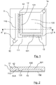
- the figure 1 is a plan, seen from above, of a microfluidic circuit 1 for implementing a method according to a preferred embodiment of the invention. This plan shows the different microfluidic channels that are formed within this microfluidic circuit. A section of this circuit microfluidic 1 is also represented on the figure 2 .
- this microfluidic circuit 1 may be composed of two superimposed plates, glued to each other.
- the circuit 1 is composed of a plate 102, which may for example be a transparent microscope slide, and a plate 101 whose faces in contact with the plate 102 are etched so as to define microchannels between the plates. two plates that are superimposed and glued to each other.
- the plate 101 may be made of a polymeric material.
- the material constituting at least one of the two plates is transparent, in order to facilitate the observation of the fluids in the microchannels. In this case, the observation of the circuit 1 makes it possible to see the microchannels by transparency, as represented by the figure 1 .
- the dimensions of these microchannels can be chosen freely by adapting the width and the depth of the engravings in the etched plate.
- the microchannels may have a width of about 100 microns and a depth of about 50 microns.
- These microchannels may also have larger dimensions, or on the contrary lower, so as to adapt to the characteristics of different fluids, or the sizes of the drops to handle.
- microfluidic circuits manufactured according to other methods known to those skilled in the art can obviously be used to implement the invention.
- microchannels are normally dimensioned so that their walls exert a constraint confining the solution or on the drops which circulate there. In most microchannels, the drops are thus confined by the upper, lower, right and left walls. Some microchannels, called “chambers" thereafter, are however dimensioned so as to exert a constraint only in one dimension, two of their substantially parallel walls (generally the upper wall and the lower wall) being close to one another. another to confine the drops, and the other walls being sufficiently distant not to confine the drops.
- the microfluidic circuit 1 must, prior to its use, be filled with an inert fluid, subsequently called carrier fluid, which is immiscible with the fluids that one wishes to manipulate in the circuit.
- This carrier fluid is generally oil, which may be supplemented with a surfactant additive product that makes it possible to avoid the spontaneous fusion of manipulated solution drops, if they come into contact. This surfactant additive may sometimes be unnecessary, depending on the characteristics of the oil used as the carrier fluid and the solution to be treated and analyzed.
- the microfluidic circuit 1 shown comprises a supply microchannel 11, dividing into two supply branches 110 and 111 extending perpendicularly to each other.
- This microchannel 11 is connected to a feed hole 10 which is pierced in one of the plates making up the microfluidic circuit 1, and into which the needle of a syringe or the end of a pipette can be inserted in order to injecting a fluid into the supply channel 11.
- the chamber 13 also has an evacuation opening connected to a hole 14 pierced through one of the plates of the circuit 1. This opening allows in particular the evacuation of a part of the carrier fluid, when the total volume of fluid inserted in the microchannels is greater than the volume of these microchannels.
- the two feed branches 110 and 111 are each connected to a plurality of drop forming nozzles 12.
- the nozzles have been shown on the figure 1 with dimensions greater than their normal dimensions. Moreover, only some of the nozzles 12 are referenced on the figure 1 .
- These drop forming nozzles 12 are microchannels, or small section conduits that can be supplied with fluid at their first end and passing a small flow of this fluid to a second end.
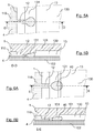
- the Figures 3A, 4A , 5A and 6A show in detail the plane of a drop forming nozzle 12 and the chamber into which it opens, at several moments of the formation of a drop of fluid.
- This nozzle and this chamber are also represented in detail by the sections of Figures 3B, 4B , 5B and 6B , which respectively correspond to the views of Figures 3A, 4A , 5A and 6A .
- the carrier fluid that fills the channels of circuit 1 is not shown in these figures.
- the second end of the nozzle 12 opens on a central chamber 13, which has an upper surface etched in the plate 101 and a lower surface formed by the plate 102.
- the upper surface of the chamber 13 has an inclined zone 131, so that the two surfaces of the chamber 13 move apart as they move away from the second end of the nozzle 12. This separation of the walls allows the confinement suffered by the solution decreases during its journey, after passing through the nozzle 12.
- the inclined zone can be replaced by a zone forming a succession of several steps in the surface of the chamber, without departing from the scope of the invention.
- the person skilled in the art knows that such a succession of steps has the same technical effect as an inclined zone.
- the walls deviate in width rather than deviate in height.
- the shape of the microchannels microfluidic circuit 1, and more precisely the succession of a drop forming nozzle 12 and a chamber 13 in which the surfaces deviate from each other away from the nozzle 12 , allows the formation of drops 40 of fluid 4, without any flow of the carrier fluid is necessary.
- the only action necessary to form these drops is indeed the introduction of the fluid 4 into the hole 10 with sufficient pressure.
- the formation of the drops can also be achieved by applying suction (or negative pressure) to the output 14 of the microfluidic circuit, after introducing the fluid 4 into the hole 10. The drops are then formed in the same manner.
- the fluid introduction pressure 4 in the microfluidic circuit 1 affects only very slightly the size of the drops 40 formed. It has thus been shown by the inventors that a multiplication per thousand of the fluid introduction pressure 4 only multiplies by two the size of the drop produced.
- the microfluidic circuit 1 thus makes it possible to produce drops 40 whose size derives mainly from the geometrical characteristics of the microchannels (and in particular from the section of the nozzle 12 and the slope of the inclined zone 131) and from the viscosity of the fluid 4.
- Each nozzle 12 can thus, when it is supplied upstream by a continuous flow of fluid, here by the fluid from the supply branches 110 and 111, provide downstream drops of homogeneous size of the same fluid.
- Such drop forming nozzles 12 which make it possible to form a stream of drops from a continuous flow of fluid without having to have a flow of carrier fluid, are described in the document WO 2011/121220 , on behalf of the plaintiffs.
- Twenty-four nozzles 12 are represented on the microfluidic circuit 1 of the figure 1 .
- a microfluidic circuit comprising 256 nozzles of height 50 microns and width 100 microns each, can decompose a sample of about 20 .mu.l of solution in about 100,000 drops in two minutes.
- the nozzles may be distributed around three sides, or four sides of a rectangular chamber, or be distributed around a part or the whole of the periphery a chamber having a different shape, for example round, hexagonal, etc.
- storage area or “trapping area”, in the present description means an area of the microfluidic circuit in which a drop can penetrate, but it can not leave without outside intervention.
- an area is etched in the upper surface of this chamber 13, so as to form a drop storage area 130, located in the middle of the chamber 13.
- the chamber 13 Around the storage area 130, the chamber 13 has upper and lower surfaces which are preferably parallel and which are sufficiently close so that the drops placed in the chamber are confined between these two surfaces, without being able to take the spherical shape which corresponds to a minimum surface energy.
- the distance between the upper surface of the chamber and its lower surface is greater (for example about 50 microns) in the storage area than in neighboring areas.
- a drop placed in this storage area may therefore take a more compact shape than a drop confined between the upper and lower surfaces of the chamber 13, around the Storage area 130.
- a drop in the storage area has less surface energy than a drop outside that area.
- a drop placed in this storage area can not leave without energy to increase its surface energy.
- the storage area 130 thus forms a space in which the drops are held, and is preferably dimensioned such that the drops are disposed in a plane, in two dimensions. All its drops contained in this area are thus directly visible from outside the microfluidic circuit, because of the transparency of at least one of the surfaces of the chamber.
- the storage area 130 is located near the place where the drops are formed.
- the drops are introduced into this storage area 130 as soon as they are formed, without any external means being necessary to move them towards this zone.
- the conformation of the walls of the chamber 13, and in particular the separation of the walls at the inclined zone 131 and the edges of the storage zone 130, makes it possible for each drop to move under the effect of its surface tension. up to this storage area. It is also possible that the drops move in the chamber 13 towards the storage area, being pushed by other drops.
- the microfluidic circuit 1 is, before use, filled with a carrier fluid.
- a carrier fluid To perform a treatment and analysis of a solution containing a biological material, an operator introduces this solution through the hole This introduction is simply done by adjusting the end of a pipette or the needle of a syringe in the hole 10 before ejecting this fluid by pressing the syringe or the pipette.
- the fluid then flows into the feed channel 11, then into its branches 110 and 111. It then passes through the various nozzles 12, at the exit of which it breaks down into drops that flow into the chamber 13. In this way, the large number of nozzles 12 distributed along the branches 110 and 111 of the feed channel, a large number of drops can be created simultaneously. These drops are captured and retained in the storage area 130, and quickly fill the entire storage area.
- the operator can monitor the filling of the chamber 13 and stop injecting the solution when the storage area 130 is completely filled, to prevent drops of the solution from escaping through the discharge opening connected to the hole 14.
- the sample volume to create enough drops to fill the storage area is known, it is also possible to inject precisely this volume of the solution, to avoid losing part of the sample. In this case, it may be useful to inject a small amount of carrier fluid into the hole 10 after the solution injection, in order to repel the solution. remaining in the feed channel 11 and its branches 110 and 111 to the chamber 13.
- the operator can withdraw the pipette or the syringe from the hole 10. Due to the retention of the drops in the storage area 130, the microfluidic circuit 1 can then be handled by the operator without the risk of escape of the drops.
- the entire microfluidic circuit 1 may for example be placed in a heating device for its thermocycling, or any other heat treatment, without risk of losing a portion of the solution sample divided into drops. It is also possible to perform other types of treatment, in addition to or instead of a heat treatment.
- an optical analysis of the drops can be performed very easily, all the drops contained in the storage zone 130 of the chamber 13 being advantageously visible by a transparent face of the microfluidic circuit 1. This analysis can advantageously be carried out automated way.
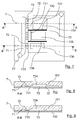
- the figure 7 is a plan, in top view, of a microfluidic circuit 7 for implementing a method according to a second possible embodiment of the invention. Sections of this microfluidic circuit 7 are also represented by the Figures 8 and 9 .
- the microfluidic circuit 7 is composed of a transparent plate 702 and a plate 701 engraved so as to define microchannels between the two plates, when they are superimposed and glued to each other.
- This microfluidic circuit 7 comprises a feed hole 70 connected to a feed microchannel 71. Twelve drop forming nozzles 72 are connected to this microchannel supply 71, and open on a chamber 73. In the embodiment shown, all the nozzles 72 (which, for the sake of clarity, are not all referenced on the figure 7 ) are the same. They are preferably of the same type as the nozzles 12 of the microfluidic circuit 1.
- the upper surface of the chamber 73 has several inclined zones 731, 732 and 733, respectively, with different slopes.
- Each of these inclined zones is located near the end of some of the nozzles 72.
- the inclined zone 731 visible in particular on the section of the figure 8
- the inclined zone 733 has a relatively steep slope, so that the lower and upper surfaces of the chamber 73 strongly deviate away from the nozzles 72.
- the inclined zone 732 has an intermediate slope.
- the drops that are produced by the nozzles 72 and the surfaces of the chamber 73 are of different sizes for each of the inclined zones.
- the drops produced at the inclined zone 731 are larger than those produced at the inclined zone 732, itself greater than that produced at the inclined zone 733.
- the storage area 734 is located near the inclined area 731 to collect the drops formed at that inclined area.
- the storage areas 735 and 736 are placed, respectively, close to the inclined zones 732 and 733.
- the dimensions of each of these storage areas are adapted to the dimensions and the quantity of the drops they are intended to receive.
- partitions 737 and 738 rising over the entire height of the chamber 73, make it possible to partially partition the latter to prevent some of the drops from moving towards a zone of storage that is not intended for them.
- the microfluidic circuit 7 makes it possible to prepare, simultaneously, samples of drops of different sizes of the same solution. These samples can then undergo the same treatments, before being analyzed. Such a method may be useful, for example, for the analysis of a solution for which the size of drops making it possible to obtain an optimal result is not known.
- the figure 10 is a plan, in top view, of a microfluidic circuit 8 for implementing a method according to a third possible embodiment of the invention.
- a section of this microfluidic circuit 8 is also represented by the figure 11 .
- This circuit 8 is largely identical to the microfluidic circuit 1. It comprises in particular the same feed hole 10, the same feed microchannel 11 dividing into two feed branches 110 and 111, and the same feed nozzles 12.
- the central chamber 83, into which the drop-forming nozzles 12 open, has inclined zones 831 identical to the inclined zones 131 of the microfluidic circuit 1.
- the upper wall of the chamber 83 is etched to define, not one, but four storage areas of the separate drops.
- These four storage areas 832, 833, 834 and 835 are, in the embodiment shown, identical. They may, however, for the purposes of an experiment, have different dimensions, for example to contain drops distributed in a different number of layers.
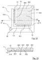
- the figure 12 is a plan, in top view of a microfluidic circuit 9 to implement a method according to a fourth possible embodiment of the invention.
- a section of this microfluidic circuit 9 is also represented by the figure 13 .
- This circuit 9 is also largely identical to the microfluidic circuit 1. It comprises in particular the same feed hole 10, the same feed microchannel 11 dividing into two feed branches 110 and 111, and the same formation nozzles 12.
- the central chamber 93, into which the drop-forming nozzles 12 open, has inclined zones 931 identical to the inclined zones 131 of the microfluidic circuit 1.
- This chamber 93 is etched to define a plurality of small holes 932.
- These holes 932 (which are not all referenced on the Figures 12 and 13 , for reasons of clarity) may have a small diameter, for example between about 10% and 120% of the diameter of a drop.
- Each of these holes 932 constitutes a storage area, or a "trap", capable of receiving a single drop.
- the forming drops fill the chamber 93, they are placed on each of these storage areas 932, where appropriate by being pushed from one storage area to another by another drop. It is also possible, according to a variant of this embodiment, that the upper wall of the chamber 93 is not perfectly parallel to its lower wall, in order to form a slight slope favoring the displacement of the drops towards the storage areas 932 which are the furthest from the drop forming nozzles 12.
- Each of the storage areas 932 is thus quickly occupied by a single drop.
- the microfluidic circuit 9 thus makes it possible to produce, process and analyze a plurality of drops which each occupy a well-defined position. precise, known in advance. Such an arrangement of the drops can greatly facilitate the optical analysis of the results of a treatment performed on the drops.
- the drops produced do not remain in prolonged contact with each other.
- the positions of the various storage areas 932 are advantageously chosen so that the trapped drops do not touch. This absence of prolonged contact between the drops considerably reduces the risk of merging several drops into one.
- the use of a surfactant additive (surfactants used to prevent the coalescence of drops between them), added to the carrier fluid, may be unnecessary. In other cases, a low-performance surfactant additive may be sufficient.
- This embodiment is therefore particularly advantageous in that it makes it possible to avoid the use of the most effective surfactant additives, which can be expensive.
- the method according to the invention therefore makes it possible to make the treatment and the analysis of a solution containing a biological material divided into drops faster, more efficient, simpler and less expensive.
- the process according to the invention allows almost all of the solution consumed to be divided into droplets that can be processed and analyzed. which is advantageous over the solutions of the prior art which induce the loss of a significant part of the treated solution.
- the drop forming nozzles can be distributed over several sides of the chamber intended to collect the drops. It is thus possible to distribute them on two sides of a square chamber, as represented for example by the embodiment of the figure 1 . It is also possible to distribute them on three or four sides of such a room. It is also possible to distribute them around a chamber of different shape, for example around almost the entire diameter of a circular chamber.
- This method also makes it possible to perform other types of treatment and analysis of solutions containing biological material.
- it is for example possible to introduce into the microfluidic circuit a solution containing a small amount of enzymes and a substrate capable of reacting with the enzyme.
- Some time after the formation of the drops it is possible to analyze them optically (either automatically, or by visual observation and counting) to determine the proportion of the drops in which an enzymatic reaction has occurred, and thus to quantify the presence of enzyme.
- the treatment applied to the drops is an incubation, consisting only in maintaining them for a sufficiently long time at temperature conditions allowing the enzymatic reaction.
- the microfluidic circuit It is also possible, for example, to introduce into the microfluidic circuit a solution containing cells and markers capable of to interact with some of these cells. Some time after the formation of the drops, it is possible to analyze them optically (either automatically, or by visual observation and counting) to determine the proportion of the drops in which cells have interacted with the markers, and thus to quantify the presence of the cells to be characterized.
- the treatment applied to the drops is a simple incubation.
- microfluidic circuit object of the invention making it possible to implement the method according to the invention, is itself particularly simple and inexpensive to manufacture. Many variants of this circuit can be implemented easily. It is thus possible, for example, that the central chamber of the circuit itself constitutes the drop storage zone, provided that suitable means prevent the drops from leaving without external intervention.
Landscapes
- Chemical & Material Sciences (AREA)
- Health & Medical Sciences (AREA)
- Chemical Kinetics & Catalysis (AREA)
- Dispersion Chemistry (AREA)
- General Health & Medical Sciences (AREA)
- Clinical Laboratory Science (AREA)
- Analytical Chemistry (AREA)
- Hematology (AREA)
- Life Sciences & Earth Sciences (AREA)
- Organic Chemistry (AREA)
- Biochemistry (AREA)
- Molecular Biology (AREA)
- Proteomics, Peptides & Aminoacids (AREA)
- Engineering & Computer Science (AREA)
- Physics & Mathematics (AREA)
- Zoology (AREA)
- Wood Science & Technology (AREA)
- Immunology (AREA)
- Fluid Mechanics (AREA)
- Microbiology (AREA)
- Biophysics (AREA)
- Biotechnology (AREA)
- Bioinformatics & Cheminformatics (AREA)
- General Engineering & Computer Science (AREA)
- Genetics & Genomics (AREA)
- Automatic Analysis And Handling Materials Therefor (AREA)
- Measuring Or Testing Involving Enzymes Or Micro-Organisms (AREA)
- Apparatus Associated With Microorganisms And Enzymes (AREA)
Applications Claiming Priority (2)
| Application Number | Priority Date | Filing Date | Title |
|---|---|---|---|
| FR1259566A FR2996545B1 (fr) | 2012-10-08 | 2012-10-08 | Procede microfluidique de traitement et d'analyse d'une solution contenant un materiel biologique, et circuit microfluidique correspondant. |
| PCT/EP2013/070966 WO2014056930A1 (fr) | 2012-10-08 | 2013-10-08 | Procédé microfluidique de traitement et d'analyse d'une solution contenant un matériel biologique, et circuit microfluidique correspondant |
Publications (2)
| Publication Number | Publication Date |
|---|---|
| EP2903738A1 EP2903738A1 (fr) | 2015-08-12 |
| EP2903738B1 true EP2903738B1 (fr) | 2016-09-14 |
Family
ID=47833099
Family Applications (1)
| Application Number | Title | Priority Date | Filing Date |
|---|---|---|---|
| EP13774166.6A Active EP2903738B1 (fr) | 2012-10-08 | 2013-10-08 | Procédé microfluidique de traitement et d'analyse d'une solution contenant un matériel biologique, et circuit microfluidique correspondant |
Country Status (5)
| Country | Link |
|---|---|
| US (5) | US9816133B2 (enExample) |
| EP (1) | EP2903738B1 (enExample) |
| JP (1) | JP6282279B2 (enExample) |
| FR (1) | FR2996545B1 (enExample) |
| WO (1) | WO2014056930A1 (enExample) |
Cited By (1)
| Publication number | Priority date | Publication date | Assignee | Title |
|---|---|---|---|---|
| US10816550B2 (en) | 2012-10-15 | 2020-10-27 | Nanocellect Biomedical, Inc. | Systems, apparatus, and methods for sorting particles |
Families Citing this family (49)
| Publication number | Priority date | Publication date | Assignee | Title |
|---|---|---|---|---|
| US9701998B2 (en) | 2012-12-14 | 2017-07-11 | 10X Genomics, Inc. | Methods and systems for processing polynucleotides |
| US9951386B2 (en) | 2014-06-26 | 2018-04-24 | 10X Genomics, Inc. | Methods and systems for processing polynucleotides |
| US10752949B2 (en) | 2012-08-14 | 2020-08-25 | 10X Genomics, Inc. | Methods and systems for processing polynucleotides |
| US10584381B2 (en) | 2012-08-14 | 2020-03-10 | 10X Genomics, Inc. | Methods and systems for processing polynucleotides |
| US10323279B2 (en) | 2012-08-14 | 2019-06-18 | 10X Genomics, Inc. | Methods and systems for processing polynucleotides |
| AU2013302756C1 (en) | 2012-08-14 | 2018-05-17 | 10X Genomics, Inc. | Microcapsule compositions and methods |
| US11591637B2 (en) | 2012-08-14 | 2023-02-28 | 10X Genomics, Inc. | Compositions and methods for sample processing |
| FR2996545B1 (fr) | 2012-10-08 | 2016-03-25 | Ecole Polytech | Procede microfluidique de traitement et d'analyse d'une solution contenant un materiel biologique, et circuit microfluidique correspondant. |
| US10533221B2 (en) | 2012-12-14 | 2020-01-14 | 10X Genomics, Inc. | Methods and systems for processing polynucleotides |
| KR20200140929A (ko) | 2013-02-08 | 2020-12-16 | 10엑스 제노믹스, 인크. | 폴리뉴클레오티드 바코드 생성 |
| BR112016023625A2 (pt) | 2014-04-10 | 2018-06-26 | 10X Genomics, Inc. | dispositivos fluídicos, sistemas e métodos para encapsular e particionar reagentes, e aplicações dos mesmos |
| WO2015200893A2 (en) | 2014-06-26 | 2015-12-30 | 10X Genomics, Inc. | Methods of analyzing nucleic acids from individual cells or cell populations |
| US12312640B2 (en) | 2014-06-26 | 2025-05-27 | 10X Genomics, Inc. | Analysis of nucleic acid sequences |
| CA2953469A1 (en) | 2014-06-26 | 2015-12-30 | 10X Genomics, Inc. | Analysis of nucleic acid sequences |
| US9975122B2 (en) | 2014-11-05 | 2018-05-22 | 10X Genomics, Inc. | Instrument systems for integrated sample processing |
| DE102014224664B3 (de) | 2014-12-02 | 2015-10-08 | Hahn-Schickard-Gesellschaft für angewandte Forschung e.V. | Vorrichtung und verfahren zur tropfenerzeugung |
| EP3285928B1 (en) | 2015-04-22 | 2020-04-08 | Stilla Technologies | Contact-less priming method for loading a solution in a microfluidic device and associated system |
| WO2017197343A2 (en) | 2016-05-12 | 2017-11-16 | 10X Genomics, Inc. | Microfluidic on-chip filters |
| WO2017197338A1 (en) | 2016-05-13 | 2017-11-16 | 10X Genomics, Inc. | Microfluidic systems and methods of use |
| US11376595B2 (en) * | 2016-11-30 | 2022-07-05 | Pilot Gene Technologies (Hangzhou) Co., Ltd. | Droplet digital PCR chip |
| US10815525B2 (en) | 2016-12-22 | 2020-10-27 | 10X Genomics, Inc. | Methods and systems for processing polynucleotides |
| US10011872B1 (en) | 2016-12-22 | 2018-07-03 | 10X Genomics, Inc. | Methods and systems for processing polynucleotides |
| US10550429B2 (en) | 2016-12-22 | 2020-02-04 | 10X Genomics, Inc. | Methods and systems for processing polynucleotides |
| EP3838268B1 (en) | 2017-02-24 | 2023-05-10 | The Regents of the University of California | Particle-drop structures and methods for making and using the same |
| WO2018183744A1 (en) | 2017-03-29 | 2018-10-04 | The Research Foundation For The State University Of New York | Microfluidic device and methods |
| EP4435113B1 (en) | 2017-05-18 | 2025-12-10 | 10X Genomics, Inc. | Methods and systems for sorting droplets and beads |
| US10544413B2 (en) | 2017-05-18 | 2020-01-28 | 10X Genomics, Inc. | Methods and systems for sorting droplets and beads |
| US10610865B2 (en) | 2017-08-22 | 2020-04-07 | 10X Genomics, Inc. | Droplet forming devices and system with differential surface properties |
| WO2019077114A1 (en) | 2017-10-20 | 2019-04-25 | Stilla Technologies | EMULSIONS HAVING IMPROVED STABILITY |
| WO2019083852A1 (en) | 2017-10-26 | 2019-05-02 | 10X Genomics, Inc. | MICROFLUIDIC CHANNEL NETWORKS FOR PARTITIONING |
| SG11201913654QA (en) | 2017-11-15 | 2020-01-30 | 10X Genomics Inc | Functionalized gel beads |
| US10829815B2 (en) | 2017-11-17 | 2020-11-10 | 10X Genomics, Inc. | Methods and systems for associating physical and genetic properties of biological particles |
| JP2019117118A (ja) * | 2017-12-27 | 2019-07-18 | 株式会社エンプラス | 流体取扱方法およびこれに用いる流体取扱装置、ならびに流体取扱システム |
| CN112399882B (zh) * | 2018-04-16 | 2023-08-01 | 派特恩生物技术有限公司 | 用于形成二维微滴阵列的方法和设备 |
| US11130120B2 (en) | 2018-10-01 | 2021-09-28 | Lifeng XIAO | Micro-pipette tip for forming micro-droplets |
| US10486155B1 (en) | 2018-10-22 | 2019-11-26 | Klaris Corporation | Vacuum-loaded, droplet-generating microfluidic chips and related methods |
| CN113661005A (zh) | 2018-11-27 | 2021-11-16 | 斯蒂拉科技公司 | 微流控芯片中优化样品加载的孔 |
| WO2020109379A1 (en) | 2018-11-27 | 2020-06-04 | Stilla Technologies | Microfluidic chip architecture with optimized phase flow |
| CN113747974A (zh) | 2019-02-28 | 2021-12-03 | 10X基因组学有限公司 | 用于提高液滴形成效率的装置、系统和方法 |
| US12186751B2 (en) | 2019-06-28 | 2025-01-07 | 10X Genomics, Inc. | Devices and systems incorporating acoustic ordering and methods of use thereof |
| US12059679B2 (en) | 2019-11-19 | 2024-08-13 | 10X Genomics, Inc. | Methods and devices for sorting droplets and particles |
| US11060141B1 (en) | 2019-12-23 | 2021-07-13 | Stilla Technologies | Multiplex drop-off digital polymerase chain reaction methods |
| US10953404B1 (en) | 2020-04-24 | 2021-03-23 | Pattern Bioscience, Inc. | Apparatuses for contactless loading and imaging of microfluidic chips and related methods |
| WO2022192683A1 (en) * | 2021-03-11 | 2022-09-15 | Virginia Tech Intellectual Properties, Inc. | Methods and apparatus for evaporation based liquid transport |
| WO2022221391A1 (en) | 2021-04-14 | 2022-10-20 | Partillion Bioscience Corporation | Nanoscale reaction chambers and methods of using the same |
| CA3155441A1 (en) * | 2021-04-20 | 2022-10-20 | National Research Council | Microfluidic chip, kit, and system for displacing independent reaction volumes of an emulsion |
| CN114471765B (zh) * | 2022-01-18 | 2023-04-21 | 北京保利微芯科技有限公司 | 离心式液滴生成芯片 |
| EP4402192B1 (en) | 2022-08-18 | 2025-07-02 | 10X Genomics, Inc. | Droplet forming devices and methods having flourous diol additives |
| EP4521118A1 (en) | 2023-09-06 | 2025-03-12 | Stilla Technologies | Loading unit for an analysis device |
Family Cites Families (25)
| Publication number | Priority date | Publication date | Assignee | Title |
|---|---|---|---|---|
| FR2720943B1 (fr) | 1994-06-09 | 1996-08-23 | Applic Transferts Technolo | Emulsions inverses stables à forte concentration en composé(s) fluoré(s) et leur utilisation pour l'administration pulmonaire de médicaments et pour la fabrication d'émulsions multiples. |
| JP3012608B1 (ja) | 1998-09-17 | 2000-02-28 | 農林水産省食品総合研究所長 | マイクロチャネル装置及び同装置を用いたエマルションの製造方法 |
| JP2001145486A (ja) | 1999-11-19 | 2001-05-29 | Natl Inst Of Advanced Industrial Science & Technology Meti | 多試料用の微小容量化学反応装置 |
| WO2002023163A1 (en) | 2000-09-15 | 2002-03-21 | California Institute Of Technology | Microfabricated crossflow devices and methods |
| JP2003153692A (ja) | 2001-09-07 | 2003-05-27 | Shinji Katsura | 核酸増幅方法 |
| EP2283917B1 (en) | 2002-05-09 | 2021-12-15 | The University of Chicago | Device for pressure-driven plug transport and reaction |
| US7041481B2 (en) | 2003-03-14 | 2006-05-09 | The Regents Of The University Of California | Chemical amplification based on fluid partitioning |
| US20050063875A1 (en) * | 2003-09-22 | 2005-03-24 | Georgia Tech Research Corporation | Micro-fluidic processor |
| FR2873171B1 (fr) | 2004-07-19 | 2007-12-07 | Centre Nat Rech Scient Cnrse | Circuit microfluidique a composant actif |
| US7759111B2 (en) | 2004-08-27 | 2010-07-20 | The Regents Of The University Of California | Cell encapsulation microfluidic device |
| US7968287B2 (en) | 2004-10-08 | 2011-06-28 | Medical Research Council Harvard University | In vitro evolution in microfluidic systems |
| ITRM20050389A1 (it) | 2005-07-22 | 2007-01-23 | Giuliani Spa | Composti e loro sali specifici per i recettori ppar ed i recettori per l'egf e loro uso in campo medico. |
| DE102005037401B4 (de) * | 2005-08-08 | 2007-09-27 | MAX-PLANCK-Gesellschaft zur Förderung der Wissenschaften e.V. | Bildung einer Emulsion in einem fluidischen Mikrosystem |
| CA2653321A1 (en) * | 2006-05-26 | 2007-12-06 | Althea Technologies, Inc. | Biochemical analysis of partitioned cells |
| FR2901717A1 (fr) * | 2006-05-30 | 2007-12-07 | Centre Nat Rech Scient | Procede de traitement de gouttes dans un circuit microfluidique. |
| US8454906B2 (en) | 2007-07-24 | 2013-06-04 | The Regents Of The University Of California | Microfabricated droplet generator for single molecule/cell genetic analysis in engineered monodispersed emulsions |
| US20090053719A1 (en) | 2007-08-03 | 2009-02-26 | The Chinese University Of Hong Kong | Analysis of nucleic acids by digital pcr |
| US9664619B2 (en) * | 2008-04-28 | 2017-05-30 | President And Fellows Of Harvard College | Microfluidic device for storage and well-defined arrangement of droplets |
| EP4512526A3 (en) | 2008-09-23 | 2025-06-04 | Bio-Rad Laboratories, Inc. | Droplet-based assay system |
| US8877512B2 (en) | 2009-01-23 | 2014-11-04 | Advanced Liquid Logic, Inc. | Bubble formation techniques using physical or chemical features to retain a gas bubble within a droplet actuator |
| FR2950544B1 (fr) | 2009-09-29 | 2011-12-09 | Ecole Polytech | Circuit microfluidique |
| EP4484577A3 (en) | 2010-02-12 | 2025-03-26 | Bio-Rad Laboratories, Inc. | Digital analyte analysis |
| FR2958186A1 (fr) * | 2010-03-30 | 2011-10-07 | Ecole Polytech | Dispositif de formation de gouttes dans un circuit microfluide. |
| US9387236B2 (en) | 2011-06-10 | 2016-07-12 | Prothera Inc. | Pharmaceutical compositions containing protease and methods for the treatment of lysosomal storage diseases |
| FR2996545B1 (fr) | 2012-10-08 | 2016-03-25 | Ecole Polytech | Procede microfluidique de traitement et d'analyse d'une solution contenant un materiel biologique, et circuit microfluidique correspondant. |
-
2012
- 2012-10-08 FR FR1259566A patent/FR2996545B1/fr active Active
-
2013
- 2013-10-08 JP JP2015535062A patent/JP6282279B2/ja active Active
- 2013-10-08 EP EP13774166.6A patent/EP2903738B1/fr active Active
- 2013-10-08 US US14/434,390 patent/US9816133B2/en active Active
- 2013-10-08 WO PCT/EP2013/070966 patent/WO2014056930A1/fr not_active Ceased
-
2017
- 2017-10-18 US US15/787,457 patent/US10501789B2/en active Active
-
2019
- 2019-12-09 US US16/707,337 patent/US11066699B2/en active Active
-
2021
- 2021-07-19 US US17/379,476 patent/US12071658B2/en active Active
-
2024
- 2024-08-05 US US18/795,007 patent/US20240392362A1/en active Pending
Cited By (1)
| Publication number | Priority date | Publication date | Assignee | Title |
|---|---|---|---|---|
| US10816550B2 (en) | 2012-10-15 | 2020-10-27 | Nanocellect Biomedical, Inc. | Systems, apparatus, and methods for sorting particles |
Also Published As
| Publication number | Publication date |
|---|---|
| US20240392362A1 (en) | 2024-11-28 |
| US20200190559A1 (en) | 2020-06-18 |
| JP2015532424A (ja) | 2015-11-09 |
| US9816133B2 (en) | 2017-11-14 |
| FR2996545A1 (fr) | 2014-04-11 |
| US20220010363A1 (en) | 2022-01-13 |
| FR2996545B1 (fr) | 2016-03-25 |
| JP6282279B2 (ja) | 2018-02-21 |
| US20180037934A1 (en) | 2018-02-08 |
| US12071658B2 (en) | 2024-08-27 |
| US20150267246A1 (en) | 2015-09-24 |
| US10501789B2 (en) | 2019-12-10 |
| EP2903738A1 (fr) | 2015-08-12 |
| US11066699B2 (en) | 2021-07-20 |
| WO2014056930A1 (fr) | 2014-04-17 |
Similar Documents
| Publication | Publication Date | Title |
|---|---|---|
| EP2903738B1 (fr) | Procédé microfluidique de traitement et d'analyse d'une solution contenant un matériel biologique, et circuit microfluidique correspondant | |
| FR2996544A1 (fr) | Circuit microfluidique permettant la mise en contact de gouttes de plusieurs fluides, et procede microfluidique correspondant. | |
| EP2119503B1 (fr) | Système microfluidique et procédé pour le tri d'amas de cellules et pour leur encapsulation en continu suite à leur tri | |
| EP3554700B1 (fr) | Puce micro fluidique de thermalisation à cycles de température variable, système utilisant une telle puce et procédé pcr pour la détection de séquences adn | |
| EP3347128B1 (fr) | Ensemble comportant un substrat de support d'échantillon liquide et son utilisation | |
| EP3941712B1 (fr) | Procédé d'impression additive tridimensionnelle | |
| WO2012143908A1 (fr) | Système microfluidique pour contrôler la concentration de molécules de stimulation d'une cible. | |
| EP3318328B1 (fr) | Equipement de tri de particules présentes dans un échantillon fluidique | |
| EP2442902B1 (fr) | Systeme microfluidique et procede pour le transfert d'elements entre phases liquides et utilisation de ce systeme pour extraire ces elements | |
| FR2866493A1 (fr) | Dispositif de controle du deplacement d'une goutte entre deux ou plusieurs substrats solides | |
| EP2680971A1 (fr) | Systeme microfluidique pour controler un profil de concentration de molecules susceptibles de stimuler une cible | |
| EP3519092A1 (fr) | Procede microfluidique de manipulation de microgouttes | |
| EP2038061B1 (fr) | Dispositif microfluidique avec materiau de volume variable | |
| CA3078319C (fr) | Dispositif et procede de coloration d'un materiau organique sur une lame | |
| EP3807001A1 (fr) | Méthode de transfert de matière dans un dispositif microfluidique ou millifluidique | |
| EP4532106A1 (fr) | Dispositif microfluidique, système et procédé de manipulation d'un fluide en écoulement | |
| FR3074810A1 (fr) | Puce echantillon micro-fluidique, systeme d'analyse utilisant une telle puce et procede pcr pour la detection de sequences adn | |
| FR3147115A1 (fr) | Puce microfluidique et procédé pour générer et trier des microgouttes monodispersées à haute fréquence | |
| WO2004091793A1 (fr) | Microdispositif de transfert collectif d'une pluralite de liquide | |
| FR3060418A1 (fr) | Puce micro fluidique, systeme utilisant une telle puce et procede pcr pour la detection de sequences adn |
Legal Events
| Date | Code | Title | Description |
|---|---|---|---|
| PUAI | Public reference made under article 153(3) epc to a published international application that has entered the european phase |
Free format text: ORIGINAL CODE: 0009012 |
|
| 17P | Request for examination filed |
Effective date: 20150508 |
|
| AK | Designated contracting states |
Kind code of ref document: A1 Designated state(s): AL AT BE BG CH CY CZ DE DK EE ES FI FR GB GR HR HU IE IS IT LI LT LU LV MC MK MT NL NO PL PT RO RS SE SI SK SM TR |
|
| AX | Request for extension of the european patent |
Extension state: BA ME |
|
| DAX | Request for extension of the european patent (deleted) | ||
| REG | Reference to a national code |
Ref country code: DE Ref legal event code: R079 Ref document number: 602013011681 Country of ref document: DE Free format text: PREVIOUS MAIN CLASS: B01L0003000000 Ipc: C12Q0001680000 |
|
| RIC1 | Information provided on ipc code assigned before grant |
Ipc: B01L 3/00 20060101ALI20160308BHEP Ipc: B01L 7/00 20060101ALI20160308BHEP Ipc: C12Q 1/68 20060101AFI20160308BHEP |
|
| GRAP | Despatch of communication of intention to grant a patent |
Free format text: ORIGINAL CODE: EPIDOSNIGR1 |
|
| INTG | Intention to grant announced |
Effective date: 20160425 |
|
| GRAS | Grant fee paid |
Free format text: ORIGINAL CODE: EPIDOSNIGR3 |
|
| GRAA | (expected) grant |
Free format text: ORIGINAL CODE: 0009210 |
|
| AK | Designated contracting states |
Kind code of ref document: B1 Designated state(s): AL AT BE BG CH CY CZ DE DK EE ES FI FR GB GR HR HU IE IS IT LI LT LU LV MC MK MT NL NO PL PT RO RS SE SI SK SM TR |
|
| REG | Reference to a national code |
Ref country code: GB Ref legal event code: FG4D Free format text: NOT ENGLISH |
|
| REG | Reference to a national code |
Ref country code: CH Ref legal event code: EP |
|
| REG | Reference to a national code |
Ref country code: IE Ref legal event code: FG4D Free format text: LANGUAGE OF EP DOCUMENT: FRENCH |
|
| REG | Reference to a national code |
Ref country code: AT Ref legal event code: REF Ref document number: 829057 Country of ref document: AT Kind code of ref document: T Effective date: 20161015 |
|
| 111L | Licence recorded |
Designated state(s): AL AT BE BG CH CY CZ DE DK EE ES FI FR GB GR HR HU IE IS IT LT LU LV MC MK MT NL NO PL PT RO RS SE SI SK SM TR Free format text: EXCLUSIVE LICENSE Name of requester: STILLA TECHNOLOGIES, FR Effective date: 20160804 |
|
| REG | Reference to a national code |
Ref country code: DE Ref legal event code: R096 Ref document number: 602013011681 Country of ref document: DE |
|
| REG | Reference to a national code |
Ref country code: FR Ref legal event code: PLFP Year of fee payment: 4 |
|
| REG | Reference to a national code |
Ref country code: CH Ref legal event code: NV Representative=s name: MICHELI AND CIE SA, CH |
|
| REG | Reference to a national code |
Ref country code: LT Ref legal event code: MG4D |
|
| REG | Reference to a national code |
Ref country code: NL Ref legal event code: MP Effective date: 20160914 |
|
| PG25 | Lapsed in a contracting state [announced via postgrant information from national office to epo] |
Ref country code: NO Free format text: LAPSE BECAUSE OF FAILURE TO SUBMIT A TRANSLATION OF THE DESCRIPTION OR TO PAY THE FEE WITHIN THE PRESCRIBED TIME-LIMIT Effective date: 20161214 Ref country code: HR Free format text: LAPSE BECAUSE OF FAILURE TO SUBMIT A TRANSLATION OF THE DESCRIPTION OR TO PAY THE FEE WITHIN THE PRESCRIBED TIME-LIMIT Effective date: 20160914 Ref country code: LT Free format text: LAPSE BECAUSE OF FAILURE TO SUBMIT A TRANSLATION OF THE DESCRIPTION OR TO PAY THE FEE WITHIN THE PRESCRIBED TIME-LIMIT Effective date: 20160914 Ref country code: FI Free format text: LAPSE BECAUSE OF FAILURE TO SUBMIT A TRANSLATION OF THE DESCRIPTION OR TO PAY THE FEE WITHIN THE PRESCRIBED TIME-LIMIT Effective date: 20160914 Ref country code: RS Free format text: LAPSE BECAUSE OF FAILURE TO SUBMIT A TRANSLATION OF THE DESCRIPTION OR TO PAY THE FEE WITHIN THE PRESCRIBED TIME-LIMIT Effective date: 20160914 |
|
| REG | Reference to a national code |
Ref country code: AT Ref legal event code: MK05 Ref document number: 829057 Country of ref document: AT Kind code of ref document: T Effective date: 20160914 |
|
| PG25 | Lapsed in a contracting state [announced via postgrant information from national office to epo] |
Ref country code: SE Free format text: LAPSE BECAUSE OF FAILURE TO SUBMIT A TRANSLATION OF THE DESCRIPTION OR TO PAY THE FEE WITHIN THE PRESCRIBED TIME-LIMIT Effective date: 20160914 Ref country code: LV Free format text: LAPSE BECAUSE OF FAILURE TO SUBMIT A TRANSLATION OF THE DESCRIPTION OR TO PAY THE FEE WITHIN THE PRESCRIBED TIME-LIMIT Effective date: 20160914 Ref country code: BE Free format text: LAPSE BECAUSE OF NON-PAYMENT OF DUE FEES Effective date: 20161031 Ref country code: GR Free format text: LAPSE BECAUSE OF FAILURE TO SUBMIT A TRANSLATION OF THE DESCRIPTION OR TO PAY THE FEE WITHIN THE PRESCRIBED TIME-LIMIT Effective date: 20161215 Ref country code: NL Free format text: LAPSE BECAUSE OF FAILURE TO SUBMIT A TRANSLATION OF THE DESCRIPTION OR TO PAY THE FEE WITHIN THE PRESCRIBED TIME-LIMIT Effective date: 20160914 |
|
| PG25 | Lapsed in a contracting state [announced via postgrant information from national office to epo] |
Ref country code: EE Free format text: LAPSE BECAUSE OF FAILURE TO SUBMIT A TRANSLATION OF THE DESCRIPTION OR TO PAY THE FEE WITHIN THE PRESCRIBED TIME-LIMIT Effective date: 20160914 Ref country code: RO Free format text: LAPSE BECAUSE OF FAILURE TO SUBMIT A TRANSLATION OF THE DESCRIPTION OR TO PAY THE FEE WITHIN THE PRESCRIBED TIME-LIMIT Effective date: 20160914 |
|
| PG25 | Lapsed in a contracting state [announced via postgrant information from national office to epo] |
Ref country code: IS Free format text: LAPSE BECAUSE OF FAILURE TO SUBMIT A TRANSLATION OF THE DESCRIPTION OR TO PAY THE FEE WITHIN THE PRESCRIBED TIME-LIMIT Effective date: 20170114 Ref country code: PT Free format text: LAPSE BECAUSE OF FAILURE TO SUBMIT A TRANSLATION OF THE DESCRIPTION OR TO PAY THE FEE WITHIN THE PRESCRIBED TIME-LIMIT Effective date: 20170116 Ref country code: BG Free format text: LAPSE BECAUSE OF FAILURE TO SUBMIT A TRANSLATION OF THE DESCRIPTION OR TO PAY THE FEE WITHIN THE PRESCRIBED TIME-LIMIT Effective date: 20161214 Ref country code: ES Free format text: LAPSE BECAUSE OF FAILURE TO SUBMIT A TRANSLATION OF THE DESCRIPTION OR TO PAY THE FEE WITHIN THE PRESCRIBED TIME-LIMIT Effective date: 20160914 Ref country code: SM Free format text: LAPSE BECAUSE OF FAILURE TO SUBMIT A TRANSLATION OF THE DESCRIPTION OR TO PAY THE FEE WITHIN THE PRESCRIBED TIME-LIMIT Effective date: 20160914 Ref country code: PL Free format text: LAPSE BECAUSE OF FAILURE TO SUBMIT A TRANSLATION OF THE DESCRIPTION OR TO PAY THE FEE WITHIN THE PRESCRIBED TIME-LIMIT Effective date: 20160914 Ref country code: CZ Free format text: LAPSE BECAUSE OF FAILURE TO SUBMIT A TRANSLATION OF THE DESCRIPTION OR TO PAY THE FEE WITHIN THE PRESCRIBED TIME-LIMIT Effective date: 20160914 Ref country code: AT Free format text: LAPSE BECAUSE OF FAILURE TO SUBMIT A TRANSLATION OF THE DESCRIPTION OR TO PAY THE FEE WITHIN THE PRESCRIBED TIME-LIMIT Effective date: 20160914 Ref country code: SK Free format text: LAPSE BECAUSE OF FAILURE TO SUBMIT A TRANSLATION OF THE DESCRIPTION OR TO PAY THE FEE WITHIN THE PRESCRIBED TIME-LIMIT Effective date: 20160914 |
|
| REG | Reference to a national code |
Ref country code: DE Ref legal event code: R097 Ref document number: 602013011681 Country of ref document: DE |
|
| PG25 | Lapsed in a contracting state [announced via postgrant information from national office to epo] |
Ref country code: IT Free format text: LAPSE BECAUSE OF FAILURE TO SUBMIT A TRANSLATION OF THE DESCRIPTION OR TO PAY THE FEE WITHIN THE PRESCRIBED TIME-LIMIT Effective date: 20160914 |
|
| PLBE | No opposition filed within time limit |
Free format text: ORIGINAL CODE: 0009261 |
|
| STAA | Information on the status of an ep patent application or granted ep patent |
Free format text: STATUS: NO OPPOSITION FILED WITHIN TIME LIMIT |
|
| REG | Reference to a national code |
Ref country code: IE Ref legal event code: MM4A |
|
| PG25 | Lapsed in a contracting state [announced via postgrant information from national office to epo] |
Ref country code: DK Free format text: LAPSE BECAUSE OF FAILURE TO SUBMIT A TRANSLATION OF THE DESCRIPTION OR TO PAY THE FEE WITHIN THE PRESCRIBED TIME-LIMIT Effective date: 20160914 |
|
| 26N | No opposition filed |
Effective date: 20170615 |
|
| PG25 | Lapsed in a contracting state [announced via postgrant information from national office to epo] |
Ref country code: LU Free format text: LAPSE BECAUSE OF NON-PAYMENT OF DUE FEES Effective date: 20161008 |
|
| REG | Reference to a national code |
Ref country code: FR Ref legal event code: PLFP Year of fee payment: 5 |
|
| PG25 | Lapsed in a contracting state [announced via postgrant information from national office to epo] |
Ref country code: SI Free format text: LAPSE BECAUSE OF FAILURE TO SUBMIT A TRANSLATION OF THE DESCRIPTION OR TO PAY THE FEE WITHIN THE PRESCRIBED TIME-LIMIT Effective date: 20160914 Ref country code: IE Free format text: LAPSE BECAUSE OF NON-PAYMENT OF DUE FEES Effective date: 20161008 |
|
| REG | Reference to a national code |
Ref country code: BE Ref legal event code: MM Effective date: 20161031 |
|
| PG25 | Lapsed in a contracting state [announced via postgrant information from national office to epo] |
Ref country code: HU Free format text: LAPSE BECAUSE OF FAILURE TO SUBMIT A TRANSLATION OF THE DESCRIPTION OR TO PAY THE FEE WITHIN THE PRESCRIBED TIME-LIMIT; INVALID AB INITIO Effective date: 20131008 |
|
| PG25 | Lapsed in a contracting state [announced via postgrant information from national office to epo] |
Ref country code: MT Free format text: LAPSE BECAUSE OF FAILURE TO SUBMIT A TRANSLATION OF THE DESCRIPTION OR TO PAY THE FEE WITHIN THE PRESCRIBED TIME-LIMIT Effective date: 20160914 Ref country code: MC Free format text: LAPSE BECAUSE OF FAILURE TO SUBMIT A TRANSLATION OF THE DESCRIPTION OR TO PAY THE FEE WITHIN THE PRESCRIBED TIME-LIMIT Effective date: 20160914 Ref country code: MK Free format text: LAPSE BECAUSE OF FAILURE TO SUBMIT A TRANSLATION OF THE DESCRIPTION OR TO PAY THE FEE WITHIN THE PRESCRIBED TIME-LIMIT Effective date: 20160914 Ref country code: CY Free format text: LAPSE BECAUSE OF FAILURE TO SUBMIT A TRANSLATION OF THE DESCRIPTION OR TO PAY THE FEE WITHIN THE PRESCRIBED TIME-LIMIT Effective date: 20160914 |
|
| REG | Reference to a national code |
Ref country code: FR Ref legal event code: PLFP Year of fee payment: 6 |
|
| PG25 | Lapsed in a contracting state [announced via postgrant information from national office to epo] |
Ref country code: TR Free format text: LAPSE BECAUSE OF FAILURE TO SUBMIT A TRANSLATION OF THE DESCRIPTION OR TO PAY THE FEE WITHIN THE PRESCRIBED TIME-LIMIT Effective date: 20160914 Ref country code: AL Free format text: LAPSE BECAUSE OF FAILURE TO SUBMIT A TRANSLATION OF THE DESCRIPTION OR TO PAY THE FEE WITHIN THE PRESCRIBED TIME-LIMIT Effective date: 20160914 |
|
| P01 | Opt-out of the competence of the unified patent court (upc) registered |
Effective date: 20230511 |
|
| REG | Reference to a national code |
Ref country code: CH Ref legal event code: U11 Free format text: ST27 STATUS EVENT CODE: U-0-0-U10-U11 (AS PROVIDED BY THE NATIONAL OFFICE) Effective date: 20251101 |
|
| PGFP | Annual fee paid to national office [announced via postgrant information from national office to epo] |
Ref country code: DE Payment date: 20251021 Year of fee payment: 13 |
|
| PGFP | Annual fee paid to national office [announced via postgrant information from national office to epo] |
Ref country code: GB Payment date: 20251022 Year of fee payment: 13 |
|
| PGFP | Annual fee paid to national office [announced via postgrant information from national office to epo] |
Ref country code: FR Payment date: 20251030 Year of fee payment: 13 |
|
| PGFP | Annual fee paid to national office [announced via postgrant information from national office to epo] |
Ref country code: CH Payment date: 20251101 Year of fee payment: 13 |