EP2903738B1 - Microfluidic process for treating and analysing a solution containing a biological material, and corresponding microfluidic circuit - Google Patents
Microfluidic process for treating and analysing a solution containing a biological material, and corresponding microfluidic circuit Download PDFInfo
- Publication number
- EP2903738B1 EP2903738B1 EP13774166.6A EP13774166A EP2903738B1 EP 2903738 B1 EP2903738 B1 EP 2903738B1 EP 13774166 A EP13774166 A EP 13774166A EP 2903738 B1 EP2903738 B1 EP 2903738B1
- Authority
- EP
- European Patent Office
- Prior art keywords
- drops
- microfluidic
- microfluidic circuit
- solution
- circuit
- Prior art date
- Legal status (The legal status is an assumption and is not a legal conclusion. Google has not performed a legal analysis and makes no representation as to the accuracy of the status listed.)
- Active
Links
- 238000000034 method Methods 0.000 title claims description 69
- 239000012620 biological material Substances 0.000 title claims description 13
- 239000012530 fluid Substances 0.000 claims description 82
- 238000003860 storage Methods 0.000 claims description 82
- 238000011282 treatment Methods 0.000 claims description 24
- 238000004458 analytical method Methods 0.000 claims description 22
- 150000007523 nucleic acids Chemical class 0.000 claims description 20
- 108020004707 nucleic acids Proteins 0.000 claims description 19
- 102000039446 nucleic acids Human genes 0.000 claims description 19
- 230000000694 effects Effects 0.000 claims description 14
- 230000003287 optical effect Effects 0.000 claims description 6
- 230000003068 static effect Effects 0.000 claims description 3
- 239000012780 transparent material Substances 0.000 claims description 2
- 238000012408 PCR amplification Methods 0.000 claims 1
- 239000012141 concentrate Substances 0.000 claims 1
- 239000000243 solution Substances 0.000 description 75
- 238000004519 manufacturing process Methods 0.000 description 13
- 239000000523 sample Substances 0.000 description 11
- 230000015572 biosynthetic process Effects 0.000 description 10
- 230000003321 amplification Effects 0.000 description 8
- 238000003199 nucleic acid amplification method Methods 0.000 description 8
- 239000004094 surface-active agent Substances 0.000 description 8
- 238000000926 separation method Methods 0.000 description 7
- 238000006073 displacement reaction Methods 0.000 description 6
- 239000000654 additive Substances 0.000 description 5
- 238000010438 heat treatment Methods 0.000 description 5
- 238000003752 polymerase chain reaction Methods 0.000 description 5
- 230000000996 additive effect Effects 0.000 description 4
- 238000007847 digital PCR Methods 0.000 description 4
- 102000004190 Enzymes Human genes 0.000 description 3
- 108090000790 Enzymes Proteins 0.000 description 3
- 238000011534 incubation Methods 0.000 description 3
- 238000012546 transfer Methods 0.000 description 3
- 230000001052 transient effect Effects 0.000 description 3
- 108020004414 DNA Proteins 0.000 description 2
- 239000013060 biological fluid Substances 0.000 description 2
- 238000006243 chemical reaction Methods 0.000 description 2
- 238000006911 enzymatic reaction Methods 0.000 description 2
- 230000004927 fusion Effects 0.000 description 2
- 238000002347 injection Methods 0.000 description 2
- 239000007924 injection Substances 0.000 description 2
- 239000000463 material Substances 0.000 description 2
- 238000005192 partition Methods 0.000 description 2
- 238000012545 processing Methods 0.000 description 2
- 230000002035 prolonged effect Effects 0.000 description 2
- 230000002269 spontaneous effect Effects 0.000 description 2
- 230000000007 visual effect Effects 0.000 description 2
- 102000053602 DNA Human genes 0.000 description 1
- 108091028043 Nucleic acid sequence Proteins 0.000 description 1
- 239000007864 aqueous solution Substances 0.000 description 1
- 239000012472 biological sample Substances 0.000 description 1
- 238000004581 coalescence Methods 0.000 description 1
- 125000004122 cyclic group Chemical group 0.000 description 1
- 230000007423 decrease Effects 0.000 description 1
- 230000001627 detrimental effect Effects 0.000 description 1
- 238000009826 distribution Methods 0.000 description 1
- 238000005530 etching Methods 0.000 description 1
- 238000002474 experimental method Methods 0.000 description 1
- 238000003384 imaging method Methods 0.000 description 1
- 238000000338 in vitro Methods 0.000 description 1
- 230000014759 maintenance of location Effects 0.000 description 1
- 238000005259 measurement Methods 0.000 description 1
- 238000002360 preparation method Methods 0.000 description 1
- 238000003825 pressing Methods 0.000 description 1
- 230000000750 progressive effect Effects 0.000 description 1
- 230000000717 retained effect Effects 0.000 description 1
- 230000000630 rising effect Effects 0.000 description 1
- 229920002477 rna polymer Polymers 0.000 description 1
- 238000003892 spreading Methods 0.000 description 1
- 239000000758 substrate Substances 0.000 description 1
- 238000012549 training Methods 0.000 description 1
- 238000011144 upstream manufacturing Methods 0.000 description 1
Images


Classifications
-
- C—CHEMISTRY; METALLURGY
- C12—BIOCHEMISTRY; BEER; SPIRITS; WINE; VINEGAR; MICROBIOLOGY; ENZYMOLOGY; MUTATION OR GENETIC ENGINEERING
- C12Q—MEASURING OR TESTING PROCESSES INVOLVING ENZYMES, NUCLEIC ACIDS OR MICROORGANISMS; COMPOSITIONS OR TEST PAPERS THEREFOR; PROCESSES OF PREPARING SUCH COMPOSITIONS; CONDITION-RESPONSIVE CONTROL IN MICROBIOLOGICAL OR ENZYMOLOGICAL PROCESSES
- C12Q1/00—Measuring or testing processes involving enzymes, nucleic acids or microorganisms; Compositions therefor; Processes of preparing such compositions
- C12Q1/68—Measuring or testing processes involving enzymes, nucleic acids or microorganisms; Compositions therefor; Processes of preparing such compositions involving nucleic acids
- C12Q1/6844—Nucleic acid amplification reactions
- C12Q1/686—Polymerase chain reaction [PCR]
-
- B—PERFORMING OPERATIONS; TRANSPORTING
- B01—PHYSICAL OR CHEMICAL PROCESSES OR APPARATUS IN GENERAL
- B01L—CHEMICAL OR PHYSICAL LABORATORY APPARATUS FOR GENERAL USE
- B01L3/00—Containers or dishes for laboratory use, e.g. laboratory glassware; Droppers
- B01L3/50—Containers for the purpose of retaining a material to be analysed, e.g. test tubes
- B01L3/502—Containers for the purpose of retaining a material to be analysed, e.g. test tubes with fluid transport, e.g. in multi-compartment structures
- B01L3/5027—Containers for the purpose of retaining a material to be analysed, e.g. test tubes with fluid transport, e.g. in multi-compartment structures by integrated microfluidic structures, i.e. dimensions of channels and chambers are such that surface tension forces are important, e.g. lab-on-a-chip
- B01L3/50273—Containers for the purpose of retaining a material to be analysed, e.g. test tubes with fluid transport, e.g. in multi-compartment structures by integrated microfluidic structures, i.e. dimensions of channels and chambers are such that surface tension forces are important, e.g. lab-on-a-chip characterised by the means or forces applied to move the fluids
-
- B—PERFORMING OPERATIONS; TRANSPORTING
- B01—PHYSICAL OR CHEMICAL PROCESSES OR APPARATUS IN GENERAL
- B01L—CHEMICAL OR PHYSICAL LABORATORY APPARATUS FOR GENERAL USE
- B01L3/00—Containers or dishes for laboratory use, e.g. laboratory glassware; Droppers
- B01L3/50—Containers for the purpose of retaining a material to be analysed, e.g. test tubes
- B01L3/502—Containers for the purpose of retaining a material to be analysed, e.g. test tubes with fluid transport, e.g. in multi-compartment structures
- B01L3/5027—Containers for the purpose of retaining a material to be analysed, e.g. test tubes with fluid transport, e.g. in multi-compartment structures by integrated microfluidic structures, i.e. dimensions of channels and chambers are such that surface tension forces are important, e.g. lab-on-a-chip
- B01L3/502761—Containers for the purpose of retaining a material to be analysed, e.g. test tubes with fluid transport, e.g. in multi-compartment structures by integrated microfluidic structures, i.e. dimensions of channels and chambers are such that surface tension forces are important, e.g. lab-on-a-chip specially adapted for handling suspended solids or molecules independently from the bulk fluid flow, e.g. for trapping or sorting beads, for physically stretching molecules
-
- B—PERFORMING OPERATIONS; TRANSPORTING
- B01—PHYSICAL OR CHEMICAL PROCESSES OR APPARATUS IN GENERAL
- B01L—CHEMICAL OR PHYSICAL LABORATORY APPARATUS FOR GENERAL USE
- B01L3/00—Containers or dishes for laboratory use, e.g. laboratory glassware; Droppers
- B01L3/50—Containers for the purpose of retaining a material to be analysed, e.g. test tubes
- B01L3/502—Containers for the purpose of retaining a material to be analysed, e.g. test tubes with fluid transport, e.g. in multi-compartment structures
- B01L3/5027—Containers for the purpose of retaining a material to be analysed, e.g. test tubes with fluid transport, e.g. in multi-compartment structures by integrated microfluidic structures, i.e. dimensions of channels and chambers are such that surface tension forces are important, e.g. lab-on-a-chip
- B01L3/502769—Containers for the purpose of retaining a material to be analysed, e.g. test tubes with fluid transport, e.g. in multi-compartment structures by integrated microfluidic structures, i.e. dimensions of channels and chambers are such that surface tension forces are important, e.g. lab-on-a-chip characterised by multiphase flow arrangements
- B01L3/502784—Containers for the purpose of retaining a material to be analysed, e.g. test tubes with fluid transport, e.g. in multi-compartment structures by integrated microfluidic structures, i.e. dimensions of channels and chambers are such that surface tension forces are important, e.g. lab-on-a-chip characterised by multiphase flow arrangements specially adapted for droplet or plug flow, e.g. digital microfluidics
- B01L3/502792—Containers for the purpose of retaining a material to be analysed, e.g. test tubes with fluid transport, e.g. in multi-compartment structures by integrated microfluidic structures, i.e. dimensions of channels and chambers are such that surface tension forces are important, e.g. lab-on-a-chip characterised by multiphase flow arrangements specially adapted for droplet or plug flow, e.g. digital microfluidics for moving individual droplets on a plate, e.g. by locally altering surface tension
-
- B—PERFORMING OPERATIONS; TRANSPORTING
- B01—PHYSICAL OR CHEMICAL PROCESSES OR APPARATUS IN GENERAL
- B01L—CHEMICAL OR PHYSICAL LABORATORY APPARATUS FOR GENERAL USE
- B01L7/00—Heating or cooling apparatus; Heat insulating devices
- B01L7/52—Heating or cooling apparatus; Heat insulating devices with provision for submitting samples to a predetermined sequence of different temperatures, e.g. for treating nucleic acid samples
-
- B—PERFORMING OPERATIONS; TRANSPORTING
- B01—PHYSICAL OR CHEMICAL PROCESSES OR APPARATUS IN GENERAL
- B01L—CHEMICAL OR PHYSICAL LABORATORY APPARATUS FOR GENERAL USE
- B01L2200/00—Solutions for specific problems relating to chemical or physical laboratory apparatus
- B01L2200/06—Fluid handling related problems
- B01L2200/0642—Filling fluids into wells by specific techniques
-
- B—PERFORMING OPERATIONS; TRANSPORTING
- B01—PHYSICAL OR CHEMICAL PROCESSES OR APPARATUS IN GENERAL
- B01L—CHEMICAL OR PHYSICAL LABORATORY APPARATUS FOR GENERAL USE
- B01L2200/00—Solutions for specific problems relating to chemical or physical laboratory apparatus
- B01L2200/06—Fluid handling related problems
- B01L2200/0647—Handling flowable solids, e.g. microscopic beads, cells, particles
- B01L2200/0652—Sorting or classification of particles or molecules
-
- B—PERFORMING OPERATIONS; TRANSPORTING
- B01—PHYSICAL OR CHEMICAL PROCESSES OR APPARATUS IN GENERAL
- B01L—CHEMICAL OR PHYSICAL LABORATORY APPARATUS FOR GENERAL USE
- B01L2200/00—Solutions for specific problems relating to chemical or physical laboratory apparatus
- B01L2200/06—Fluid handling related problems
- B01L2200/0647—Handling flowable solids, e.g. microscopic beads, cells, particles
- B01L2200/0668—Trapping microscopic beads
-
- B—PERFORMING OPERATIONS; TRANSPORTING
- B01—PHYSICAL OR CHEMICAL PROCESSES OR APPARATUS IN GENERAL
- B01L—CHEMICAL OR PHYSICAL LABORATORY APPARATUS FOR GENERAL USE
- B01L2300/00—Additional constructional details
- B01L2300/08—Geometry, shape and general structure
- B01L2300/0809—Geometry, shape and general structure rectangular shaped
- B01L2300/0816—Cards, e.g. flat sample carriers usually with flow in two horizontal directions
-
- B—PERFORMING OPERATIONS; TRANSPORTING
- B01—PHYSICAL OR CHEMICAL PROCESSES OR APPARATUS IN GENERAL
- B01L—CHEMICAL OR PHYSICAL LABORATORY APPARATUS FOR GENERAL USE
- B01L2300/00—Additional constructional details
- B01L2300/08—Geometry, shape and general structure
- B01L2300/0861—Configuration of multiple channels and/or chambers in a single devices
- B01L2300/0864—Configuration of multiple channels and/or chambers in a single devices comprising only one inlet and multiple receiving wells, e.g. for separation, splitting
-
- B—PERFORMING OPERATIONS; TRANSPORTING
- B01—PHYSICAL OR CHEMICAL PROCESSES OR APPARATUS IN GENERAL
- B01L—CHEMICAL OR PHYSICAL LABORATORY APPARATUS FOR GENERAL USE
- B01L2300/00—Additional constructional details
- B01L2300/08—Geometry, shape and general structure
- B01L2300/0861—Configuration of multiple channels and/or chambers in a single devices
- B01L2300/0867—Multiple inlets and one sample wells, e.g. mixing, dilution
-
- B—PERFORMING OPERATIONS; TRANSPORTING
- B01—PHYSICAL OR CHEMICAL PROCESSES OR APPARATUS IN GENERAL
- B01L—CHEMICAL OR PHYSICAL LABORATORY APPARATUS FOR GENERAL USE
- B01L2400/00—Moving or stopping fluids
- B01L2400/04—Moving fluids with specific forces or mechanical means
- B01L2400/0403—Moving fluids with specific forces or mechanical means specific forces
- B01L2400/0457—Moving fluids with specific forces or mechanical means specific forces passive flow or gravitation
-
- B—PERFORMING OPERATIONS; TRANSPORTING
- B01—PHYSICAL OR CHEMICAL PROCESSES OR APPARATUS IN GENERAL
- B01L—CHEMICAL OR PHYSICAL LABORATORY APPARATUS FOR GENERAL USE
- B01L2400/00—Moving or stopping fluids
- B01L2400/04—Moving fluids with specific forces or mechanical means
- B01L2400/0403—Moving fluids with specific forces or mechanical means specific forces
- B01L2400/0463—Hydrodynamic forces, venturi nozzles
-
- B—PERFORMING OPERATIONS; TRANSPORTING
- B01—PHYSICAL OR CHEMICAL PROCESSES OR APPARATUS IN GENERAL
- B01L—CHEMICAL OR PHYSICAL LABORATORY APPARATUS FOR GENERAL USE
- B01L2400/00—Moving or stopping fluids
- B01L2400/08—Regulating or influencing the flow resistance
- B01L2400/084—Passive control of flow resistance
Definitions
- the present invention relates to a process for the treatment and analysis of a solution containing a biological material, using a microfluidic method in which the solution is divided into a plurality of drops.
- the invention also relates to a microfluidic circuit, allowing the manipulation of very small quantities of fluids, in particular to implement such a method.
- microfluidic processes for manufacturing and handling, in suitable microfluidic circuits drops of a first fluid placed in a second fluid, called carrier fluid.
- the first fluid is generally an aqueous solution, divided into drops with a volume of the order of 10 to 100 ⁇ m 3 .
- the carrier fluid is generally oil, which may be supplemented with a surfactant product to prevent the spontaneous fusion of the manipulated fluid drops, if they come into contact.
- a flow, or flow, of carrier fluid is used to divide the solution containing the nucleic acid into a large quantity of drops.
- concentration of the nucleic acid in the solution is chosen so that, statistically, a small number of drops contains a molecule of the desired nucleic acid.
- the drops are placed in a container for thermocycling, allowing for polymerase chain amplification of the nucleic acid. They are then introduced into a channel to be analyzed optically, one after the other, to detect those which contained, before thermocycling, at least one occurrence of the nucleic acid, and which after this thermocycling contain a large amount of this nucleic acid.
- the first drops, produced during a transient phase have dimensions that are not not appropriate. Only the drops produced during a second phase, which have more homogeneous dimensions, can be exploited for polymerase chain amplification.
- This method therefore involves the loss of a significant part of the initial sample of solution containing the nucleic acid. Other losses of a part of this solution are generated by the necessary transfers between different containers. This process can therefore generate significant losses of the sample, which can be of the order of 25%.
- the biological samples being sometimes extremely rare and expensive, such a loss represents a significant disadvantage.
- This method also has certain disadvantages. Thus, it imposes to have an initial drop of a well-defined size, which can be divided into drops of size suitable for subsequent processing and measurement.
- the method used for the production of the initial drops by divusion of a solution stream under the action of a carrier fluid flow, assumes a transient phase at the beginning of the production of the drops, during which the flows of the solution containing the nucleic acid and the carrier fluid must equilibrate.
- the drops formed during this transient phase therefore have an unsuitable size.
- the successive divisions of these initial drops cause the introduction into the channel of a large number of drops of inappropriate size, which can not be validly analyzed. As a result, only a portion of the biological fluid sample can be analyzed, while another portion, representing about 10% of the sample, is lost.
- the drops can be produced and divided only under the action of a carrier fluid flow, a large amount of this carrier fluid is introduced into the channel at the same time as the drops. As a result, the concentration of the drops in the carrier fluid in this channel is not optimal.
- this method requiring the balancing of a solution stream containing the nucleic acid and a flow of biological fluid, is relatively complex to implement and requires special skills. Indeed, without a rigorous implementation of the method, the drops produced may have non-homogeneous sizes, which is detrimental to the analysis.
- the present invention aims to overcome these disadvantages of the prior art.
- the present invention aims to provide a method of treating and analyzing a solution containing a biological material, implementing a microfluidic method in which the solution is divided into a plurality of drops, which is faster to implement that the processes of the prior art, more efficient, simpler and less expensive, which requires less training operators to implement the process, and which allows to process and usefully analyze a larger proportion biological material consumed.
- Another object of the present invention is to provide a microfluidic circuit for the implementation of such a method.
- the invention particularly aims, according to at least one of its embodiments, to provide such a method, and the microfluidic circuit making it possible to implement it, which makes it possible to perform a simpler, more efficient, digital drop-by-drop PCR. less expensive than the processes of the prior art.
- This process advantageously allows the reaction generated by the treatment to proceed independently in each of the drops. It can be implemented particularly easily, in a single microfluidic circuit in which the different steps are performed. Moreover, the drops can be manufactured and transported independently of the presence or absence of a flow of the carrier fluid. The size of the drops, in particular, does not depend strongly on a movement of the carrier fluid, and is homogeneous from the beginning of their formation. It is thus possible that all, or almost all, of the consumed sample undergoes the treatment and is analyzed.
- the microchannels of the microfluidic circuit are configured so that the solution circulates between walls that deviate from each other, causing a variation in the confinement of the solution.
- the spacing of each wall may be progressive (steep walls) or steep (on).
- the surface tension of the solution that is to say the interfacial tension between the solution and the carrier fluid with which it is in contact, imposes on the flow of solution a form taking into account this variable confinement, which results in the separation of drops.
- This drop separation method in which the surface tension of the solution is used to cause the detachment of the drop, is therefore radically different from the methods requiring a carrier fluid flow to create a drop shear solution, in contrasting the surface tension of the solution which tends to bring together the solution. It also has the advantage of not requiring balancing of a carrier fluid flow with the solution stream, which simplifies the process.
- the displacement of the drops is also caused by the separation of the walls coupled with the effects of the surface tension of the drops. It can be caused directly, a drop moving between walls deviating, under the effect of its surface tension, or indirectly, the drop being pushed by another drop, which itself moves between the walls s 'spreading, under the effect of its surface tension.
- the drops are maintained, after their formation and their displacement, in at least one storage zone, which is an area in which it can penetrate, but from which it can not leave without external intervention (for example a flow of fluid carrier giving them sufficient energy to go out). They can thus very easily be subjected to a treatment and be analyzed.
- the carrier fluid in which the drops are detached and displaced is substantially static.
- the manufacture and displacement of the drops are thus more reliable, insofar as they are defined solely by the configuration of the walls of the microchannels, without being disturbed by a flow of carrier fluid.
- the carrier fluid although substantially static, undergoes slight disturbances caused by the displacement of the drops.
- the treatment applied to the drops comprises variations in the temperature of the drops.
- the temperature variations are applied to the entire microfluidic circuit containing the drops. They can also be applied to sub-regions or to individual drops, for example successively one after the other.
- Temperature variations, or thermocycling may for example allow the realization of a polymerase chain reaction.
- Other treatments may also be applied, such as for example an incubation, of keeping the drops, for a sufficiently long time, at temperature conditions allowing a reaction to occur.
- the analysis of the drops is an optical analysis.
- At least one of the storage zones is constituted by a zone in which the drops have a lower surface energy than in the neighboring zones.
- the configuration of the microchannels microfluidic circuit allows the drops are maintained in the storage area, which can also be called trapping area, under the effect of their surface tension. They are therefore effectively maintained in this storage zone, independently of a possible flow of carrier fluid, as long as this flow of carrier fluid or other external action, for example the thrust of another drop, does not give them a sufficient energy to raise its surface energy through an area surrounding the storage area.
- the biological material contained in the solution comprises at least one nucleic acid
- the treatment applied to the drops is a polymerase chain reaction, making it possible to increase the concentration of at least one sequence of said nucleic acid.
- the method according to the invention thus makes it possible to carry out a chain amplification by digital droplet polymerase, which is simpler and more effective than those used in the prior art.
- the invention also relates to a microfluidic circuit, in which are defined microchannels that can contain fluids, the circuit comprising at least one device for forming drops of a solution in a carrier fluid, and at least one drop storage zone as well as produced.
- the drop forming devices comprise microchannel wall portions, spaced apart from each other so as to detach a drop of the solution under the effect of the surface tension of the solution
- the microfluidic circuit comprises means for guiding drops comprising microchannel wall portions, deviating from each other so as to move the drops to the storage area under the effect of the drop voltage.
- This circuit makes it possible in particular to implement the method described above, particularly easily. No flow of carrier fluid is indeed necessary in this circuit, the only introduction of the solution into the circuit automatically causing its division into drops and the displacement of these drops to the storage area where they can be processed and analyzed.
- At least one of the storage zones is constituted by a zone of a microchannel in which the walls of said microchannel are farther apart from one another than in the neighboring zones.
- This storage area may for example be defined in a chamber, in which the drops are confined only by an upper wall and a lower wall. An area of this room in which these two walls are more distant allows the drops to be less confined. This zone then retains the drops and constitutes a storage area.
- the microfluidic circuit contains at least two distinct storage zones.
- the microfluidic circuit comprises at least two drop-forming device, each making it possible to form drops of different volumes.
- the circuit makes it possible to simultaneously process and analyze drops of several sizes.
- the drop guide means are configured to guide the drops of different volumes to separate storage areas.
- At least one of said storage areas is configured so as to be able to receive only one drop.
- each drop can be maintained in its storage area, or individual trapping. This allows a better positioning of drops, in particular to facilitate their analysis.
- the drops being, in this case, not in contact with each other during their treatment and analysis, they are not likely to merge. It is therefore possible, in this case, to reduce the surfactant properties of the carrier fluid without inconvenience.
- At least one of the storage areas is configured to receive drops in the same plane.
- Such an embodiment makes it easier to analyze the drops.
- At least one of the storage areas is configured so as to distribute the drops it contains over at least two superposed planes.
- Such an embodiment assuming a high storage area, makes it possible to process and analyze a larger number of drops.
- the microfluidic circuit is constituted, at least in part, a transparent material for seeing at least one of the storage areas from outside the circuit.
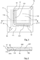
- the figure 1 is a plan, seen from above, of a microfluidic circuit 1 for implementing a method according to a preferred embodiment of the invention. This plan shows the different microfluidic channels that are formed within this microfluidic circuit. A section of this circuit microfluidic 1 is also represented on the figure 2 .
- this microfluidic circuit 1 may be composed of two superimposed plates, glued to each other.
- the circuit 1 is composed of a plate 102, which may for example be a transparent microscope slide, and a plate 101 whose faces in contact with the plate 102 are etched so as to define microchannels between the plates. two plates that are superimposed and glued to each other.
- the plate 101 may be made of a polymeric material.
- the material constituting at least one of the two plates is transparent, in order to facilitate the observation of the fluids in the microchannels. In this case, the observation of the circuit 1 makes it possible to see the microchannels by transparency, as represented by the figure 1 .
- the dimensions of these microchannels can be chosen freely by adapting the width and the depth of the engravings in the etched plate.
- the microchannels may have a width of about 100 microns and a depth of about 50 microns.
- These microchannels may also have larger dimensions, or on the contrary lower, so as to adapt to the characteristics of different fluids, or the sizes of the drops to handle.
- microfluidic circuits manufactured according to other methods known to those skilled in the art can obviously be used to implement the invention.
- microchannels are normally dimensioned so that their walls exert a constraint confining the solution or on the drops which circulate there. In most microchannels, the drops are thus confined by the upper, lower, right and left walls. Some microchannels, called “chambers" thereafter, are however dimensioned so as to exert a constraint only in one dimension, two of their substantially parallel walls (generally the upper wall and the lower wall) being close to one another. another to confine the drops, and the other walls being sufficiently distant not to confine the drops.
- the microfluidic circuit 1 must, prior to its use, be filled with an inert fluid, subsequently called carrier fluid, which is immiscible with the fluids that one wishes to manipulate in the circuit.
- This carrier fluid is generally oil, which may be supplemented with a surfactant additive product that makes it possible to avoid the spontaneous fusion of manipulated solution drops, if they come into contact. This surfactant additive may sometimes be unnecessary, depending on the characteristics of the oil used as the carrier fluid and the solution to be treated and analyzed.
- the microfluidic circuit 1 shown comprises a supply microchannel 11, dividing into two supply branches 110 and 111 extending perpendicularly to each other.
- This microchannel 11 is connected to a feed hole 10 which is pierced in one of the plates making up the microfluidic circuit 1, and into which the needle of a syringe or the end of a pipette can be inserted in order to injecting a fluid into the supply channel 11.
- the chamber 13 also has an evacuation opening connected to a hole 14 pierced through one of the plates of the circuit 1. This opening allows in particular the evacuation of a part of the carrier fluid, when the total volume of fluid inserted in the microchannels is greater than the volume of these microchannels.
- the two feed branches 110 and 111 are each connected to a plurality of drop forming nozzles 12.
- the nozzles have been shown on the figure 1 with dimensions greater than their normal dimensions. Moreover, only some of the nozzles 12 are referenced on the figure 1 .
- These drop forming nozzles 12 are microchannels, or small section conduits that can be supplied with fluid at their first end and passing a small flow of this fluid to a second end.
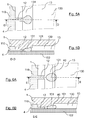
- the Figures 3A, 4A , 5A and 6A show in detail the plane of a drop forming nozzle 12 and the chamber into which it opens, at several moments of the formation of a drop of fluid.
- This nozzle and this chamber are also represented in detail by the sections of Figures 3B, 4B , 5B and 6B , which respectively correspond to the views of Figures 3A, 4A , 5A and 6A .
- the carrier fluid that fills the channels of circuit 1 is not shown in these figures.
- the second end of the nozzle 12 opens on a central chamber 13, which has an upper surface etched in the plate 101 and a lower surface formed by the plate 102.
- the upper surface of the chamber 13 has an inclined zone 131, so that the two surfaces of the chamber 13 move apart as they move away from the second end of the nozzle 12. This separation of the walls allows the confinement suffered by the solution decreases during its journey, after passing through the nozzle 12.
- the inclined zone can be replaced by a zone forming a succession of several steps in the surface of the chamber, without departing from the scope of the invention.
- the person skilled in the art knows that such a succession of steps has the same technical effect as an inclined zone.
- the walls deviate in width rather than deviate in height.
- the shape of the microchannels microfluidic circuit 1, and more precisely the succession of a drop forming nozzle 12 and a chamber 13 in which the surfaces deviate from each other away from the nozzle 12 , allows the formation of drops 40 of fluid 4, without any flow of the carrier fluid is necessary.
- the only action necessary to form these drops is indeed the introduction of the fluid 4 into the hole 10 with sufficient pressure.
- the formation of the drops can also be achieved by applying suction (or negative pressure) to the output 14 of the microfluidic circuit, after introducing the fluid 4 into the hole 10. The drops are then formed in the same manner.
- the fluid introduction pressure 4 in the microfluidic circuit 1 affects only very slightly the size of the drops 40 formed. It has thus been shown by the inventors that a multiplication per thousand of the fluid introduction pressure 4 only multiplies by two the size of the drop produced.
- the microfluidic circuit 1 thus makes it possible to produce drops 40 whose size derives mainly from the geometrical characteristics of the microchannels (and in particular from the section of the nozzle 12 and the slope of the inclined zone 131) and from the viscosity of the fluid 4.
- Each nozzle 12 can thus, when it is supplied upstream by a continuous flow of fluid, here by the fluid from the supply branches 110 and 111, provide downstream drops of homogeneous size of the same fluid.
- Such drop forming nozzles 12 which make it possible to form a stream of drops from a continuous flow of fluid without having to have a flow of carrier fluid, are described in the document WO 2011/121220 , on behalf of the plaintiffs.
- Twenty-four nozzles 12 are represented on the microfluidic circuit 1 of the figure 1 .
- a microfluidic circuit comprising 256 nozzles of height 50 microns and width 100 microns each, can decompose a sample of about 20 .mu.l of solution in about 100,000 drops in two minutes.
- the nozzles may be distributed around three sides, or four sides of a rectangular chamber, or be distributed around a part or the whole of the periphery a chamber having a different shape, for example round, hexagonal, etc.
- storage area or “trapping area”, in the present description means an area of the microfluidic circuit in which a drop can penetrate, but it can not leave without outside intervention.
- an area is etched in the upper surface of this chamber 13, so as to form a drop storage area 130, located in the middle of the chamber 13.
- the chamber 13 Around the storage area 130, the chamber 13 has upper and lower surfaces which are preferably parallel and which are sufficiently close so that the drops placed in the chamber are confined between these two surfaces, without being able to take the spherical shape which corresponds to a minimum surface energy.
- the distance between the upper surface of the chamber and its lower surface is greater (for example about 50 microns) in the storage area than in neighboring areas.
- a drop placed in this storage area may therefore take a more compact shape than a drop confined between the upper and lower surfaces of the chamber 13, around the Storage area 130.
- a drop in the storage area has less surface energy than a drop outside that area.
- a drop placed in this storage area can not leave without energy to increase its surface energy.
- the storage area 130 thus forms a space in which the drops are held, and is preferably dimensioned such that the drops are disposed in a plane, in two dimensions. All its drops contained in this area are thus directly visible from outside the microfluidic circuit, because of the transparency of at least one of the surfaces of the chamber.
- the storage area 130 is located near the place where the drops are formed.
- the drops are introduced into this storage area 130 as soon as they are formed, without any external means being necessary to move them towards this zone.
- the conformation of the walls of the chamber 13, and in particular the separation of the walls at the inclined zone 131 and the edges of the storage zone 130, makes it possible for each drop to move under the effect of its surface tension. up to this storage area. It is also possible that the drops move in the chamber 13 towards the storage area, being pushed by other drops.
- the microfluidic circuit 1 is, before use, filled with a carrier fluid.
- a carrier fluid To perform a treatment and analysis of a solution containing a biological material, an operator introduces this solution through the hole This introduction is simply done by adjusting the end of a pipette or the needle of a syringe in the hole 10 before ejecting this fluid by pressing the syringe or the pipette.
- the fluid then flows into the feed channel 11, then into its branches 110 and 111. It then passes through the various nozzles 12, at the exit of which it breaks down into drops that flow into the chamber 13. In this way, the large number of nozzles 12 distributed along the branches 110 and 111 of the feed channel, a large number of drops can be created simultaneously. These drops are captured and retained in the storage area 130, and quickly fill the entire storage area.
- the operator can monitor the filling of the chamber 13 and stop injecting the solution when the storage area 130 is completely filled, to prevent drops of the solution from escaping through the discharge opening connected to the hole 14.
- the sample volume to create enough drops to fill the storage area is known, it is also possible to inject precisely this volume of the solution, to avoid losing part of the sample. In this case, it may be useful to inject a small amount of carrier fluid into the hole 10 after the solution injection, in order to repel the solution. remaining in the feed channel 11 and its branches 110 and 111 to the chamber 13.
- the operator can withdraw the pipette or the syringe from the hole 10. Due to the retention of the drops in the storage area 130, the microfluidic circuit 1 can then be handled by the operator without the risk of escape of the drops.
- the entire microfluidic circuit 1 may for example be placed in a heating device for its thermocycling, or any other heat treatment, without risk of losing a portion of the solution sample divided into drops. It is also possible to perform other types of treatment, in addition to or instead of a heat treatment.
- an optical analysis of the drops can be performed very easily, all the drops contained in the storage zone 130 of the chamber 13 being advantageously visible by a transparent face of the microfluidic circuit 1. This analysis can advantageously be carried out automated way.
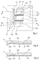
- the figure 7 is a plan, in top view, of a microfluidic circuit 7 for implementing a method according to a second possible embodiment of the invention. Sections of this microfluidic circuit 7 are also represented by the Figures 8 and 9 .
- the microfluidic circuit 7 is composed of a transparent plate 702 and a plate 701 engraved so as to define microchannels between the two plates, when they are superimposed and glued to each other.
- This microfluidic circuit 7 comprises a feed hole 70 connected to a feed microchannel 71. Twelve drop forming nozzles 72 are connected to this microchannel supply 71, and open on a chamber 73. In the embodiment shown, all the nozzles 72 (which, for the sake of clarity, are not all referenced on the figure 7 ) are the same. They are preferably of the same type as the nozzles 12 of the microfluidic circuit 1.
- the upper surface of the chamber 73 has several inclined zones 731, 732 and 733, respectively, with different slopes.
- Each of these inclined zones is located near the end of some of the nozzles 72.
- the inclined zone 731 visible in particular on the section of the figure 8
- the inclined zone 733 has a relatively steep slope, so that the lower and upper surfaces of the chamber 73 strongly deviate away from the nozzles 72.
- the inclined zone 732 has an intermediate slope.
- the drops that are produced by the nozzles 72 and the surfaces of the chamber 73 are of different sizes for each of the inclined zones.
- the drops produced at the inclined zone 731 are larger than those produced at the inclined zone 732, itself greater than that produced at the inclined zone 733.
- the storage area 734 is located near the inclined area 731 to collect the drops formed at that inclined area.
- the storage areas 735 and 736 are placed, respectively, close to the inclined zones 732 and 733.
- the dimensions of each of these storage areas are adapted to the dimensions and the quantity of the drops they are intended to receive.
- partitions 737 and 738 rising over the entire height of the chamber 73, make it possible to partially partition the latter to prevent some of the drops from moving towards a zone of storage that is not intended for them.
- the microfluidic circuit 7 makes it possible to prepare, simultaneously, samples of drops of different sizes of the same solution. These samples can then undergo the same treatments, before being analyzed. Such a method may be useful, for example, for the analysis of a solution for which the size of drops making it possible to obtain an optimal result is not known.
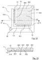
- the figure 10 is a plan, in top view, of a microfluidic circuit 8 for implementing a method according to a third possible embodiment of the invention.
- a section of this microfluidic circuit 8 is also represented by the figure 11 .
- This circuit 8 is largely identical to the microfluidic circuit 1. It comprises in particular the same feed hole 10, the same feed microchannel 11 dividing into two feed branches 110 and 111, and the same feed nozzles 12.
- the central chamber 83, into which the drop-forming nozzles 12 open, has inclined zones 831 identical to the inclined zones 131 of the microfluidic circuit 1.
- the upper wall of the chamber 83 is etched to define, not one, but four storage areas of the separate drops.
- These four storage areas 832, 833, 834 and 835 are, in the embodiment shown, identical. They may, however, for the purposes of an experiment, have different dimensions, for example to contain drops distributed in a different number of layers.
- the figure 12 is a plan, in top view of a microfluidic circuit 9 to implement a method according to a fourth possible embodiment of the invention.
- a section of this microfluidic circuit 9 is also represented by the figure 13 .
- This circuit 9 is also largely identical to the microfluidic circuit 1. It comprises in particular the same feed hole 10, the same feed microchannel 11 dividing into two feed branches 110 and 111, and the same formation nozzles 12.
- the central chamber 93, into which the drop-forming nozzles 12 open, has inclined zones 931 identical to the inclined zones 131 of the microfluidic circuit 1.
- This chamber 93 is etched to define a plurality of small holes 932.
- These holes 932 (which are not all referenced on the Figures 12 and 13 , for reasons of clarity) may have a small diameter, for example between about 10% and 120% of the diameter of a drop.
- Each of these holes 932 constitutes a storage area, or a "trap", capable of receiving a single drop.
- the forming drops fill the chamber 93, they are placed on each of these storage areas 932, where appropriate by being pushed from one storage area to another by another drop. It is also possible, according to a variant of this embodiment, that the upper wall of the chamber 93 is not perfectly parallel to its lower wall, in order to form a slight slope favoring the displacement of the drops towards the storage areas 932 which are the furthest from the drop forming nozzles 12.
- Each of the storage areas 932 is thus quickly occupied by a single drop.
- the microfluidic circuit 9 thus makes it possible to produce, process and analyze a plurality of drops which each occupy a well-defined position. precise, known in advance. Such an arrangement of the drops can greatly facilitate the optical analysis of the results of a treatment performed on the drops.
- the drops produced do not remain in prolonged contact with each other.
- the positions of the various storage areas 932 are advantageously chosen so that the trapped drops do not touch. This absence of prolonged contact between the drops considerably reduces the risk of merging several drops into one.
- the use of a surfactant additive (surfactants used to prevent the coalescence of drops between them), added to the carrier fluid, may be unnecessary. In other cases, a low-performance surfactant additive may be sufficient.
- This embodiment is therefore particularly advantageous in that it makes it possible to avoid the use of the most effective surfactant additives, which can be expensive.
- the method according to the invention therefore makes it possible to make the treatment and the analysis of a solution containing a biological material divided into drops faster, more efficient, simpler and less expensive.
- the process according to the invention allows almost all of the solution consumed to be divided into droplets that can be processed and analyzed. which is advantageous over the solutions of the prior art which induce the loss of a significant part of the treated solution.
- the drop forming nozzles can be distributed over several sides of the chamber intended to collect the drops. It is thus possible to distribute them on two sides of a square chamber, as represented for example by the embodiment of the figure 1 . It is also possible to distribute them on three or four sides of such a room. It is also possible to distribute them around a chamber of different shape, for example around almost the entire diameter of a circular chamber.
- This method also makes it possible to perform other types of treatment and analysis of solutions containing biological material.
- it is for example possible to introduce into the microfluidic circuit a solution containing a small amount of enzymes and a substrate capable of reacting with the enzyme.
- Some time after the formation of the drops it is possible to analyze them optically (either automatically, or by visual observation and counting) to determine the proportion of the drops in which an enzymatic reaction has occurred, and thus to quantify the presence of enzyme.
- the treatment applied to the drops is an incubation, consisting only in maintaining them for a sufficiently long time at temperature conditions allowing the enzymatic reaction.
- the microfluidic circuit It is also possible, for example, to introduce into the microfluidic circuit a solution containing cells and markers capable of to interact with some of these cells. Some time after the formation of the drops, it is possible to analyze them optically (either automatically, or by visual observation and counting) to determine the proportion of the drops in which cells have interacted with the markers, and thus to quantify the presence of the cells to be characterized.
- the treatment applied to the drops is a simple incubation.
- microfluidic circuit object of the invention making it possible to implement the method according to the invention, is itself particularly simple and inexpensive to manufacture. Many variants of this circuit can be implemented easily. It is thus possible, for example, that the central chamber of the circuit itself constitutes the drop storage zone, provided that suitable means prevent the drops from leaving without external intervention.
Landscapes
- Chemical & Material Sciences (AREA)
- Health & Medical Sciences (AREA)
- Chemical Kinetics & Catalysis (AREA)
- Dispersion Chemistry (AREA)
- General Health & Medical Sciences (AREA)
- Clinical Laboratory Science (AREA)
- Analytical Chemistry (AREA)
- Hematology (AREA)
- Life Sciences & Earth Sciences (AREA)
- Organic Chemistry (AREA)
- Biochemistry (AREA)
- Molecular Biology (AREA)
- Proteomics, Peptides & Aminoacids (AREA)
- Physics & Mathematics (AREA)
- Zoology (AREA)
- Engineering & Computer Science (AREA)
- Wood Science & Technology (AREA)
- Biotechnology (AREA)
- Microbiology (AREA)
- Immunology (AREA)
- Biophysics (AREA)
- Fluid Mechanics (AREA)
- Bioinformatics & Cheminformatics (AREA)
- General Engineering & Computer Science (AREA)
- Genetics & Genomics (AREA)
- Automatic Analysis And Handling Materials Therefor (AREA)
- Measuring Or Testing Involving Enzymes Or Micro-Organisms (AREA)
- Apparatus Associated With Microorganisms And Enzymes (AREA)
Description
La présente invention concerne un procédé de traitement et d'analyse d'une solution contenant un matériel biologique, mettant en oeuvre une méthode microfluidique dans laquelle la solution est divisée en une pluralité de gouttes.The present invention relates to a process for the treatment and analysis of a solution containing a biological material, using a microfluidic method in which the solution is divided into a plurality of drops.
L'invention concerne également un circuit microfluidique, permettant la manipulation de très petites quantités de fluides, permettant notamment de mettre en oeuvre un tel procédé.The invention also relates to a microfluidic circuit, allowing the manipulation of very small quantities of fluids, in particular to implement such a method.
On connaît, notamment des documents
Il a été proposé d'utiliser de tels procédés microfluidiques pour appliquer des traitements à une solution contenant un matériel biologique, suivis d'analyses de la solution traitée. Il a été notamment envisagé d'utiliser de telles techniques pour mise en oeuvre de méthodes d'amplification en chaîne par polymérase (couramment désignée par l'acronyme « PCR » pour l'expression anglaise « Polymerase Chain Reaction ») qui permettent de copier en grand nombre une séquence d'acide nucléique, tel que de l'ADN (acronyme pour «Acide Désoxyribonucléique ») ou de l'ARN (acronyme pour « Acide Ribonucléique »). Pour réaliser cette amplification, on prépare une solution contenant une faible quantité d'acide nucléique, que l'on soumet à un traitement thermique appelé thermocyclage, consistant en des variations cycliques de température. Ces variations de température permettent des duplications forcées des molécules d'acide nucléique présentes dans la solution. Il est ainsi possible d'augmenter très fortement la concentration de l'acide nucléique dans la solution.It has been proposed to use such microfluidic methods for applying treatments to a solution containing biological material, followed by analyzes of the treated solution. In particular, it has been envisaged to use such techniques for implementing polymerase chain reaction methods (commonly referred to by the acronym "PCR" for the English expression "Polymerase Chain Reaction") which make it possible to copy in vitro. a large number of nucleic acid sequence, such as DNA (acronym for "Deoxyribonucleic acid") or RNA (acronym for "Ribonucleic acid"). To carry out this amplification, a solution containing a small amount of nucleic acid is prepared, which is subjected to a heat treatment called thermocycling, consisting of cyclic temperature variations. These temperature variations allow for forced duplications of the nucleic acid molecules present in the solution. It is thus possible to increase very strongly the concentration of the nucleic acid in the solution.
Ces méthodes d'amplification en chaîne par polymérase, qui peuvent se décliner en un grand nombre de variantes, sont bien connues de l'homme du métier de la biologie moléculaire. Les méthodes d'amplification en chaîne par polymérase utilisant les procédés microfluidiques pour diviser la solution contenant l'acide nucléique en de nombreuses portions de faible volume, avant l'amplification, sont également connues en elles-mêmes de l'homme du métier, et sont couramment appelées « PCR digitales ».These polymerase chain reaction methods, which can be broken down into a large number of variants, are well known to those skilled in the field of molecular biology. Polymerase chain amplification methods using microfluidic methods to divide the nucleic acid-containing solution into many low volume portions prior to amplification are also known per se to those skilled in the art, and are commonly called "digital PCR".
On connaît notamment du document
Ce procédé nécessite l'utilisation d'équipements nombreux et couteux pour, d'une part, produire les gouttes, puis pour assurer le thermocyclage, et enfin pour analyser les gouttes après leur thermocyclage. Par ailleurs, ces opérations successives sont longues et nécessitent des compétences importantes. Une amplification en chaine par polymérase selon ce procédé est en conséquence longue, couteuse, et ne peut être réalisée que par des opérateurs spécialement formés.This process requires the use of numerous and expensive equipment for, on the one hand, to produce the drops, then to ensure thermocycling, and finally to analyze the drops after their thermocycling. Moreover, these successive operations are long and require important skills. Polymerase chain amplification according to this method is therefore long and expensive, and can only be performed by specially trained operators.
Par ailleurs, lorsque l'on utilise un flux de fluide porteur pour produire des gouttes à partir de l'échantillon de solution contenant l'acide nucléique, les premières gouttes, produites au cours d'une phase transitoire, présentent des dimensions qui ne sont pas appropriées. Seules les gouttes produites lors d'une seconde phase, qui présentent des dimensions plus homogènes, peuvent être exploitées pour l'amplification en chaine par polymérase. Ce procédé implique donc la perte d'une part significative de l'échantillon initial de solution contenant l'acide nucléique. D'autres pertes d'une partie de cette solution sont générées par les transferts nécessaires entre différents récipients. Ce procédé peut donc engendrer des pertes importantes de l'échantillon, pouvant être de l'ordre de 25 %. Les échantillons biologiques étant parfois extrêmement rares et couteux, une telle perte représente un inconvénient important.Moreover, when a carrier fluid flow is used to produce drops from the solution sample containing the nucleic acid, the first drops, produced during a transient phase, have dimensions that are not not appropriate. Only the drops produced during a second phase, which have more homogeneous dimensions, can be exploited for polymerase chain amplification. This method therefore involves the loss of a significant part of the initial sample of solution containing the nucleic acid. Other losses of a part of this solution are generated by the necessary transfers between different containers. This process can therefore generate significant losses of the sample, which can be of the order of 25%. The biological samples being sometimes extremely rare and expensive, such a loss represents a significant disadvantage.
On connaît également, de l'article
Ce procédé présente également certains inconvénients. Ainsi, il impose de disposer d'une goutte initiale d'une taille bien définie, qui puisse être divisée en gouttes de taille adaptée au traitement et à la mesure ultérieurs. Or, la méthode utilisée pour la production des gouttes initiales, par divusion d'un flux de solution sous l'action d'un flux de fluide porteur, suppose une phase transitoire au début de la production des gouttes, au cours de laquelle les écoulements de la solution contenant l'acide nucléique et du fluide porteur doivent s'équilibrer. Les gouttes formées au cours de cette phase transitoire présentent donc une taille non adaptée. Les divisions successives de ces gouttes initiales entrainent l'introduction dans le canal d'un grand nombre de gouttes de taille inadaptée, qui ne peuvent pas être validement analysées. En conséquence, seule une partie de l'échantillon de fluide biologique peut être analysée, une autre part, représentant environ 10 % de l'échantillon, étant perdue.This method also has certain disadvantages. Thus, it imposes to have an initial drop of a well-defined size, which can be divided into drops of size suitable for subsequent processing and measurement. However, the method used for the production of the initial drops, by divusion of a solution stream under the action of a carrier fluid flow, assumes a transient phase at the beginning of the production of the drops, during which the flows of the solution containing the nucleic acid and the carrier fluid must equilibrate. The drops formed during this transient phase therefore have an unsuitable size. The successive divisions of these initial drops cause the introduction into the channel of a large number of drops of inappropriate size, which can not be validly analyzed. As a result, only a portion of the biological fluid sample can be analyzed, while another portion, representing about 10% of the sample, is lost.
Par ailleurs, les gouttes ne pouvant être produites et divisées que sous l'action d'un flux de fluide porteur, une grande quantité de ce fluide porteur est introduite dans le canal en même temps que les gouttes. En conséquence, la concentration des gouttes dans le fluide porteur, dans ce canal, n'est pas optimale.Moreover, the drops can be produced and divided only under the action of a carrier fluid flow, a large amount of this carrier fluid is introduced into the channel at the same time as the drops. As a result, the concentration of the drops in the carrier fluid in this channel is not optimal.
Enfin, ce procédé, nécessitant l'équilibrage d'un flux de solution contenant l'acide nucléique et d'un flux de fluide biologique, est relativement complexe à mettre en oeuvre et nécessite des compétences particulières. En effet, sans une mise en oeuvre rigoureuse du procédé, les gouttes produites peuvent présenter des tailles non homogènes, ce qui est préjudiciable à l'analyse.Finally, this method, requiring the balancing of a solution stream containing the nucleic acid and a flow of biological fluid, is relatively complex to implement and requires special skills. Indeed, without a rigorous implementation of the method, the drops produced may have non-homogeneous sizes, which is detrimental to the analysis.
La présente invention a pour objectif de palier ces inconvénients de l'art antérieur.The present invention aims to overcome these disadvantages of the prior art.
En particulier, la présente invention a pour objectif de proposer un procédé de traitement et d'analyse d'une solution contenant un matériel biologique, mettant en oeuvre une méthode microfluidique dans laquelle la solution est divisée en une pluralité de gouttes, qui soit plus rapide à mettre en oeuvre que les procédés de l'art antérieur, plus efficace, plus simple et moins couteuse, qui nécessite une formation moindre des opérateurs devant mettre en oeuvre le procédé, et qui permette de traiter et d'analyser utilement une proportion plus importante du matériel biologique consommé.In particular, the present invention aims to provide a method of treating and analyzing a solution containing a biological material, implementing a microfluidic method in which the solution is divided into a plurality of drops, which is faster to implement that the processes of the prior art, more efficient, simpler and less expensive, which requires less training operators to implement the process, and which allows to process and usefully analyze a larger proportion biological material consumed.
Un autre objectif de la présente invention est de fournir un circuit microfluidique permettant la mise en oeuvre d'un tel procédé.Another object of the present invention is to provide a microfluidic circuit for the implementation of such a method.
L'invention a notamment pour objectif, selon au moins un de ses modes de réalisation, de fournir un tel procédé, et le circuit microfluidique permettant de le mettre en oeuvre, qui permette de réaliser une PCR digitale par gouttes plus simple, plus efficace et moins couteuse que les procédés de l'art antérieur.The invention particularly aims, according to at least one of its embodiments, to provide such a method, and the microfluidic circuit making it possible to implement it, which makes it possible to perform a simpler, more efficient, digital drop-by-drop PCR. less expensive than the processes of the prior art.
Ces objectifs, ainsi que d'autres qui apparaîtront plus clairement par la suite, sont atteints à l'aide d'un procédé microfluidique de traitement et d'analyse d'une solution contenant un matériel biologique, le procédé comprenant, selon l'invention, les étapes suivantes :
- introduction de la solution dans des microcanaux d'un circuit microfluidique ;
- détachement de gouttes de la solution dans un fluide porteur, causé par l'écartement des parois des microcanaux, couplé avec les effets de la tension de surface de la solution ;
- déplacement d'au moins une partie des gouttes dans le fluide porteur vers au moins une zone de stockage de gouttes dans le circuit microfluidique, causé par l'écartement des parois des microcanaux, couplé avec les effets de la tension de surface des gouttes ;
- application d'un traitement aux gouttes situées dans la ou les zones de stockage ;
- analyse des gouttes situées dans la ou les zones de stockage.
- introducing the solution into microchannels of a microfluidic circuit;
- detachment of drops from the solution in a carrier fluid, caused by the separation of the microchannel walls, coupled with the effects of the surface tension of the solution;
- moving at least a portion of the drops in the carrier fluid to at least one drop storage area in the microfluidic circuit, caused by the spacing of the microchannel walls, coupled with the effects of the droplet surface tension;
- application of a droplet treatment located in the storage area or zones;
- analysis of the drops located in the storage area or zones.
Ce procédé permet avantageusement que la réaction générée par le traitement se déroule de façon indépendante dans chacune des gouttes. Il peut être mis en oeuvre particulièrement facilement, dans un seul circuit microfluidique dans lequel sont réalisées les différentes étapes. Par ailleurs, les gouttes peuvent être fabriquées et transportées indépendamment de la présence ou non d'un écoulement du fluide porteur. La taille des gouttes, notamment, ne dépend pas fortement d'un mouvement du fluide porteur, et est homogène dès le début de leur formation. Il est ainsi possible que la totalité, ou la quasi-totalité de l'échantillon consommé subisse le traitement et soit analysé.This process advantageously allows the reaction generated by the treatment to proceed independently in each of the drops. It can be implemented particularly easily, in a single microfluidic circuit in which the different steps are performed. Moreover, the drops can be manufactured and transported independently of the presence or absence of a flow of the carrier fluid. The size of the drops, in particular, does not depend strongly on a movement of the carrier fluid, and is homogeneous from the beginning of their formation. It is thus possible that all, or almost all, of the consumed sample undergoes the treatment and is analyzed.
Pour cela, les microcanaux du circuit microfluidique sont configurés pour que la solution y circule entre des parois qui s'écartent les unes des autres, en causant une variation du confinement de la solution. L'écartement de chaque paroi peut être progressif (parois en pentes) ou abrupt (marche). La tension de surface de la solution, c'est à dire la tension interfaciale entre la solution et le fluide porteur avec lequel elle est en contact, impose au flux de solution une forme tenant compte de ce confinement variable, qui aboutit à la séparation de gouttes.For this, the microchannels of the microfluidic circuit are configured so that the solution circulates between walls that deviate from each other, causing a variation in the confinement of the solution. The spacing of each wall may be progressive (steep walls) or steep (on). The surface tension of the solution, that is to say the interfacial tension between the solution and the carrier fluid with which it is in contact, imposes on the flow of solution a form taking into account this variable confinement, which results in the separation of drops.
Cette méthode de séparation de gouttes, dans laquelle la tension de surface de la solution est utilisée pour causer le détachement de la goutte, se distingue donc radicalement des méthodes nécessitant un flux de fluide porteur pour créer une goutte par cisaillement de la solution, en s'opposant à la tension de surface de la solution qui tend au contraire à rassembler la solution. Elle présente également l'avantage de ne pas exiger d'équilibrage d'un flux de fluide porteur avec le flux de solution, ce qui simplifie le procédé.This drop separation method, in which the surface tension of the solution is used to cause the detachment of the drop, is therefore radically different from the methods requiring a carrier fluid flow to create a drop shear solution, in contrasting the surface tension of the solution which tends to bring together the solution. It also has the advantage of not requiring balancing of a carrier fluid flow with the solution stream, which simplifies the process.
Le déplacement des gouttes est également causé par l'écartement des parois couplé avec les effets de la tension de surface des gouttes. Il peut être causé directement, une goutte se déplaçant entre des parois s'écartant, sous l'effet de sa tension de surface, ou indirectement, la goutte étant poussée par une autre goutte, qui elle-même se se déplace entre les parois s'écartant, sous l'effet de sa tension de surface.The displacement of the drops is also caused by the separation of the walls coupled with the effects of the surface tension of the drops. It can be caused directly, a drop moving between walls deviating, under the effect of its surface tension, or indirectly, the drop being pushed by another drop, which itself moves between the walls s 'spreading, under the effect of its surface tension.
Enfin, les gouttes sont maintenues, après leur formation et leur déplacement, dans au moins une zone de stockage, qui est une zone dans laquelle elle peuvent pénétrer, mais dont elle ne peuvent pas sortir sans une intervention extérieure (par exemple un flux de fluide porteur leur conférant une énergie suffisante pour sortir). Elles peuvent ainsi très facilement être soumises à un traitement et être analysées.Finally, the drops are maintained, after their formation and their displacement, in at least one storage zone, which is an area in which it can penetrate, but from which it can not leave without external intervention (for example a flow of fluid carrier giving them sufficient energy to go out). They can thus very easily be subjected to a treatment and be analyzed.
Avantageusement, le fluide porteur dans lequel les gouttes sont détachées et déplacées est sensiblement statique.Advantageously, the carrier fluid in which the drops are detached and displaced is substantially static.
La fabrication et le déplacement des gouttes sont ainsi ainsi plus fiables, dans la mesure où ils sont définis uniquement par la configuration des parois des microcanaux, sans être perturbés par un écoulement de fluide porteur. Bien entendu, le fluide porteur, bien que sensiblement statique, subit de légères perturbations causées par le déplacement des gouttes.The manufacture and displacement of the drops are thus more reliable, insofar as they are defined solely by the configuration of the walls of the microchannels, without being disturbed by a flow of carrier fluid. Of course, the carrier fluid, although substantially static, undergoes slight disturbances caused by the displacement of the drops.
Selon un mode de réalisation avantageux de l'invention, le traitement appliqué aux gouttes comprend des variations de la température des gouttes.According to an advantageous embodiment of the invention, the treatment applied to the drops comprises variations in the temperature of the drops.
Préférentiellement, dans ce cas, les variations de température sont appliquées à l'ensemble du circuit microfluidique contenant les gouttes. Elles peuvent aussi être appliquées à des sous-régions ou bien à des gouttes individuelles, par exemple successivement les unes après les autres.Preferably, in this case, the temperature variations are applied to the entire microfluidic circuit containing the drops. They can also be applied to sub-regions or to individual drops, for example successively one after the other.
Ces variations de températures peuvent en effet être facilement appliqué au circuit microfluidique et à l'ensemble des gouttes qu'il contient. Les transferts des gouttes d'un récipient vers un autre sont ainsi évités.These temperature variations can indeed be easily applied to the microfluidic circuit and to all the drops it contains. Transfers of drops from one container to another are thus avoided.
Les variations de température, ou thermocyclage, peuvent par exemple permettre la réalisation d'une amplification en chaîne par polymérase. D'autres traitements peuvent également être appliqués, comme par exemple une incubation, consistant à maintenir les gouttes, pendant un temps suffisamment long, à des conditions de température permettant qu'une réaction se produise.Temperature variations, or thermocycling, may for example allow the realization of a polymerase chain reaction. Other treatments may also be applied, such as for example an incubation, of keeping the drops, for a sufficiently long time, at temperature conditions allowing a reaction to occur.
Préférentiellement, l'analyse des gouttes est une analyse optique.Preferably, the analysis of the drops is an optical analysis.
Cette analyse peut être réalisée facilement, à travers les parois du circuit microfluidique, sans qu'aucun transfert des gouttes ne soit nécessaire.This analysis can be performed easily, through the walls of the microfluidic circuit, without any transfer of the drops is necessary.
Selon un mode de réalisation avantageux de l'invention, au moins une des zones de stockage est constituée par une zone dans laquelle les gouttes présentent une énergie de surface plus faible que dans les zones voisines.According to an advantageous embodiment of the invention, at least one of the storage zones is constituted by a zone in which the drops have a lower surface energy than in the neighboring zones.
Ainsi, la configuration des microcanaux du circuit microfluidique permet que les gouttes soient maintenues dans la zone de stockage, qui peut également être appellée zone de piégeage, sous l'effet de leur tension de surface. Elles sont donc maintenue efficacement dans cette zone de stockage, indépendamment d'un éventuel flux de fluide porteur, tant que ce flux de fluide porteur ou une autre action extérieure, par exemple la poussée d'une autre goutte, ne leur confère une énergie suffisante pour élever son énergie de surface en passant dans une zone entourant la zone de stockage.Thus, the configuration of the microchannels microfluidic circuit allows the drops are maintained in the storage area, which can also be called trapping area, under the effect of their surface tension. They are therefore effectively maintained in this storage zone, independently of a possible flow of carrier fluid, as long as this flow of carrier fluid or other external action, for example the thrust of another drop, does not give them a sufficient energy to raise its surface energy through an area surrounding the storage area.
De façon avantageuse, le matériel biologique contenu dans la solution comprend au moins un acide nucléique, et le traitement appliqué aux gouttes est une amplification en chaîne par polymérase, permettant d'augmenter la concentration d'au moins une séquence dudit acide nucléique.Advantageously, the biological material contained in the solution comprises at least one nucleic acid, and the treatment applied to the drops is a polymerase chain reaction, making it possible to increase the concentration of at least one sequence of said nucleic acid.
Le procédé selon l'invention permet ainsi de réaliser une amplification en chaîne par polymérase digitale par gouttes, qui est plus simple et plus efficace que celles mises en oeuvre dans l'art antérieur.The method according to the invention thus makes it possible to carry out a chain amplification by digital droplet polymerase, which is simpler and more effective than those used in the prior art.
L'invention concerne également un circuit microfluidique, dans lequel sont définis des microcanaux pouvant contenir des fluides, le circuit comprenant au moins un dispositif de formation de gouttes d'une solution dans un fluide porteur, et au moins une zone de stockage des gouttes ainsi produites. Selon l'invention, les dispositifs de formation des gouttes comprennent des portions de paroi des microcanaux, s'écartant les unes des autres de façon à détacher une goutte de la solution sous l'effet de la tension de surface de la solution, et le circuit microfluidique comprend des moyens de guidage des gouttes comprenant des portions de paroi des microcanaux, s'écartant les unes des autres de façon à déplacer les gouttes vers la zone de stockage sous l'effet de la tension des gouttes.The invention also relates to a microfluidic circuit, in which are defined microchannels that can contain fluids, the circuit comprising at least one device for forming drops of a solution in a carrier fluid, and at least one drop storage zone as well as produced. According to the invention, the drop forming devices comprise microchannel wall portions, spaced apart from each other so as to detach a drop of the solution under the effect of the surface tension of the solution, and the microfluidic circuit comprises means for guiding drops comprising microchannel wall portions, deviating from each other so as to move the drops to the storage area under the effect of the drop voltage.
Ce circuit permet notamment la mise en oeuvre du procédé décrit ci-dessus, de façon particulièrement facile. Aucun flux de fluide porteur n'est en effet nécessaire dans ce circuit, la seule introduction de la solution dans le circuit entrainant automatiquement sa division en gouttes et le déplacement de ces gouttes vers la zone de stockage où elles peuvent être traitées et analysées.This circuit makes it possible in particular to implement the method described above, particularly easily. No flow of carrier fluid is indeed necessary in this circuit, the only introduction of the solution into the circuit automatically causing its division into drops and the displacement of these drops to the storage area where they can be processed and analyzed.
Préférentiellement, au moins une des zones de stockage est constituée par une zone d'un microcanal dans laquelle les parois dudit microcanal sont plus éloignées les unes des autres que dans les zones voisines.Preferably, at least one of the storage zones is constituted by a zone of a microchannel in which the walls of said microchannel are farther apart from one another than in the neighboring zones.
Cette zone de stockage peut par exemple être définie dans une chambre, dans la quelle les gouttes ne sont confinées que par une paroi supérieure et une paroi inférieure. Une zone de cette chambre dans laquelle ces deux parois sont plus éloignées permet aux gouttes d'y être moins confinées. Cette zone retient alors les gouttes et constitue une zone de stockage.This storage area may for example be defined in a chamber, in which the drops are confined only by an upper wall and a lower wall. An area of this room in which these two walls are more distant allows the drops to be less confined. This zone then retains the drops and constitutes a storage area.
Selon un mode de réalisation avantageux, le circuit microfluidique contient au moins deux zones de stockage distinctes.According to an advantageous embodiment, the microfluidic circuit contains at least two distinct storage zones.
Il est ainsi possible de traiter et d'analyser simultanément plusieurs groupes de gouttes distincts.It is thus possible to treat and analyze simultaneously several groups of separate drops.
De façon avantageuse, le circuit microfluidique comprend au moins deux dispositif de formation de gouttes, permettant chacun de former des gouttes de volumes différents.Advantageously, the microfluidic circuit comprises at least two drop-forming device, each making it possible to form drops of different volumes.
Ainsi, le circuit permet de traiter et d'analyser simultanément des gouttes de plusieurs tailles.Thus, the circuit makes it possible to simultaneously process and analyze drops of several sizes.
Avantageusement, dans ce cas, les moyens de guidage des gouttes sont configurés de façon à guider les gouttes de volumes différents vers des zones de stockage distinctes.Advantageously, in this case, the drop guide means are configured to guide the drops of different volumes to separate storage areas.
Selon un mode de réalisation avantageux, au moins une desdites zones de stockage est configurée de manière à ne pouvoir recevoir qu'une goutte.According to an advantageous embodiment, at least one of said storage areas is configured so as to be able to receive only one drop.
Dans ce cas, chaque goutte peut être maintenue dans sa zone de stockage, ou de piégeage individuelle. Cela permet un meilleur positionnement de gouttes, permettant notamment de faciliter leur analyse. Les gouttes n'étant, dans ce cas, pas en contact les unes avec les autres pendant leur traitement et leur analyse, elles ne risquent pas de fusionner. Il est donc possible, dans ce cas, de réduire les propriétés surfactantes du fluide porteur sans inconvénient.In this case, each drop can be maintained in its storage area, or individual trapping. This allows a better positioning of drops, in particular to facilitate their analysis. The drops being, in this case, not in contact with each other during their treatment and analysis, they are not likely to merge. It is therefore possible, in this case, to reduce the surfactant properties of the carrier fluid without inconvenience.
Selon un autre mode de réalisation avantageux, au moins une des zones de stockage est configurée de manière à recevoir des gouttes dans un même plan.According to another advantageous embodiment, at least one of the storage areas is configured to receive drops in the same plane.
Un tel mode de réalisation permet de faciliter l'analyse des gouttes.Such an embodiment makes it easier to analyze the drops.
Selon un autre mode de réalisation avantageux, au moins une des zones de stockage est configurée de manière à répartir sur au moins deux plans superposés les gouttes qu'elle contient.According to another advantageous embodiment, at least one of the storage areas is configured so as to distribute the drops it contains over at least two superposed planes.
Un tel mode de réalisation, supposant une zone de stockage de grande hauteur, permet de traiter et d'analyser un plus grand nombre de gouttes.Such an embodiment, assuming a high storage area, makes it possible to process and analyze a larger number of drops.
De préférence, le circuit microfluidique est constitué, au moins en partie, d'un matériau transparent permettant de voir au moins l'une des zones de stockage, depuis l'extérieur du circuit.Preferably, the microfluidic circuit is constituted, at least in part, a transparent material for seeing at least one of the storage areas from outside the circuit.
L'analyse optique des gouttes après leur traitement est ainsi facilitée.The optical analysis of the drops after their treatment is thus facilitated.
La présente invention sera mieux comprise à la lecture de la description suivante de modes de réalisation préférés, donnés à titre illustratif et non limitatif, et accompagnée de figures, parmi lesquelles :
- la
figure 1 est un plan, en vue de dessus, d'un circuit microfluidique permettant la mise en oeuvre d'un procédé selon un premier mode de réalisation de l'invention ; - la
figure 2 est une section du circuit microfluidique de lafigure 1 ; - les
figures 3A, 4A ,5A et 6A sont des détails du plan de lafigure 1 , à différents moments de l'utilisation du circuit microfluidique ; - les
figures 3B, 4B ,5B et 6B sont des sections correspondant respectivement auxfigures 3A, 4A ,5A et 6A ; - les
figures 7, 8 sont respectivement un plan et deux sections d'un circuit microfluidique permettant la mise en oeuvre d'un procédé selon un second mode de réalisation possible de l'invention ;et 9 - les
figures 10 et 11 sont respectivement un plan et une section d'un circuit microfluidique permettant la mise en oeuvre d'un procédé selon un troisième mode de réalisation possible de l'invention ; - les
figures 12 et 13 sont respectivement un plan et une section d'un circuit microfluidique permettant la mise en oeuvre d'un procédé selon un quatrième mode de réalisation possible de l'invention.
- the
figure 1 is a plan, in plan view, of a microfluidic circuit for carrying out a method according to a first embodiment of the invention; - the
figure 2 is a section of the microfluidic circuit of thefigure 1 ; - the
Figures 3A, 4A ,5A and 6A are details of the plan of thefigure 1 , at different times of use of the microfluidic circuit; - the
Figures 3B, 4B ,5B and 6B are sections corresponding respectively toFigures 3A, 4A ,5A and 6A ; - the
Figures 7, 8 and 9 are respectively a plane and two sections of a microfluidic circuit for carrying out a method according to a second possible embodiment of the invention; - the
Figures 10 and 11 are respectively a plane and a section of a microfluidic circuit for carrying out a method according to a third possible embodiment of the invention; - the
Figures 12 and 13 are respectively a plane and a section of a microfluidic circuit for carrying out a method according to a fourth possible embodiment of the invention.
La
De façon connue en elle-même, ce circuit microfluidique 1 peut être composé de deux plaques superposées, collées l'une à l'autre. Ainsi, le circuit 1 est composé d'une plaque 102, qui peut par exemple être une lame transparente de microscope, et d'une plaque 101, dont la faces en contact avec la plaque 102 est gravée de façon à définir des microcanaux entre les deux plaques qui sont superposées et collées l'une à l'autre. La plaque 101 peut être constituée d'un matériau polymère. De préférence, le matériau constituant au moins l'une des deux plaques est transparent, afin de faciliter l'observation des fluides dans les microcanaux. Dans ce cas, l'observation du circuit 1 permet de voir les microcanaux par transparence, comme le représente la
De façon connue, les dimensions de ces microcanaux peuvent être choisies librement en adaptant la largeur et la profondeur des gravures dans la plaque gravée. Par exemple, les microcanaux peuvent avoir une largeur de 100 µm environ et une profondeur de 50 µm environ. Ces microcanaux peuvent également présenter des dimensions plus importantes, ou au contraire plus faibles, de façon à s'adapter aux caractéristiques de différents fluides, ou aux tailles des gouttes à manipuler. Il est à noter que des circuits microfluidiques fabriqués selon d'autres méthodes connues de l'homme du métier peuvent évidemment être utilisés pour mettre en oeuvre l'invention.In known manner, the dimensions of these microchannels can be chosen freely by adapting the width and the depth of the engravings in the etched plate. For example, the microchannels may have a width of about 100 microns and a depth of about 50 microns. These microchannels may also have larger dimensions, or on the contrary lower, so as to adapt to the characteristics of different fluids, or the sizes of the drops to handle. It should be noted that microfluidic circuits manufactured according to other methods known to those skilled in the art can obviously be used to implement the invention.
Ces microcanaux sont normalement dimensionnés pour que leurs parois exercent une contrainte confinant la solution ou sur les gouttes qui y circulent. Dans la plupart des microcanaux, les gouttes sont ainsi confinées par les parois supérieure, inférieure, droite et gauche. Certains microcanaux, appelés « chambres » par la suite, sont cependant dimensionnés de façon à n'exercer une contrainte que dans une dimensions, deux de leurs parois sensiblement parallèles (généralement la paroi supérieure et la paroi inférieure) étant proches l'une de l'autre pour confiner les gouttes, et les autres parois étant suffisamment éloignées pour ne pas confiner les gouttes.These microchannels are normally dimensioned so that their walls exert a constraint confining the solution or on the drops which circulate there. In most microchannels, the drops are thus confined by the upper, lower, right and left walls. Some microchannels, called "chambers" thereafter, are however dimensioned so as to exert a constraint only in one dimension, two of their substantially parallel walls (generally the upper wall and the lower wall) being close to one another. another to confine the drops, and the other walls being sufficiently distant not to confine the drops.
Le circuit microfluidique 1 doit, préalablement à son utilisation, être rempli d'un fluide inerte, appelé par la suite fluide porteur, qui n'est pas miscible avec les fluides que l'on souhaite manipuler dans le circuit. Ce fluide porteur est généralement de l'huile, pouvant être additionnée d'un produit additif surfactant permettant d'éviter la fusion spontanée de gouttes de solution manipulées, si elles entrent en contact. Cet additif surfactant peut parfois être inutile, en fonction des caractéristiques de l'huile utilisée comme fluide porteur et de la solution à traiter et analyser.The
Le circuit microfluidique 1 représenté comporte un microcanal d'alimentation 11, se divisant en deux branches d'alimentation 110 et 111 s'étendant perpendiculairement l'un à l'autre. Ce microcanal 11 est connecté à un trou d'alimentation 10 qui est percé dans l'une des plaques composant le circuit microfluidique 1, et dans lequel peut être introduite l'aiguille d'une seringue ou l'extrémité d'une pipette afin d'injecter un fluide dans le canal d'alimentation 11.The
La chambre 13 présente également une ouverture d'évacuation reliée à un trou 14 percé à travers l'une des plaques du circuit 1. Cette ouverture permet notamment l'évacuation d'une partie du fluide porteur, quand le volume total de fluide inséré dans les microcanaux est supérieur au volume de ces microcanaux.The
Les deux branches d'alimentation 110 et 111 sont chacune connectées à une pluralité de buses de formation de gouttes 12. Pour des raisons de clarté, les buses ont été représentées sur la
Ces buses de formation de gouttes 12 sont des microcanaux, ou conduites de faible section pouvant être alimentées en fluide par leur première extrémité et faisant passer un faible écoulement de ce fluide vers une deuxième extrémité. Les
Comme le montrent ces figures, la deuxième extrémité de la buse 12 débouche sur une chambre centrale 13, qui présente une surface supérieure gravée dans la plaque 101 et une surface inférieure constituée par la plaque 102. A proximité de la seconde extrémité de la buse 12, la surface supérieure de la chambre 13 présente une zone inclinée 131, de telle sorte que les deux surfaces de la chambre 13 s'écartent quand elles s'éloignent de la seconde extrémité de la buse 12. Cet écartement des parois permet que le confinement subi par la solution diminue au cours de son trajet, après son passage dans la buse 12.As shown in these figures, the second end of the
Il est à noter que, selon une variante possible non représentée sur les figures, la zone inclinée peut être remplacée par une zone formant une succession de plusieurs marches dans la surface de la chambre, sans sortir du cadre de l'invention. L'homme du métier sait en effet qu'une telle succession de marches présente le même effet technique qu'une zone inclinée. De même, il serait possible selon d'autres modes de réalisation, que les parois s'écartent en largeur plutôt que de s'écarter en hauteur.It should be noted that, according to a possible variant not shown in the figures, the inclined zone can be replaced by a zone forming a succession of several steps in the surface of the chamber, without departing from the scope of the invention. The person skilled in the art knows that such a succession of steps has the same technical effect as an inclined zone. Similarly, it would be possible according to other embodiments, that the walls deviate in width rather than deviate in height.
Comme le montrent les
Cet écartement des surfaces tend à attirer le fluide 4 loin de la buse 12. En effet, le fluide tend à prendre une forme la plus proche possible d'une sphère, qui est la forme dans laquelle son énergie de surface est minimale. Il tend donc à se déplacer vers les espaces dans lesquels il est moins confiné. Cette attraction déforme le front de fluide, comme le montrent les
Ainsi, la forme des microcanaux du circuit microfluidique 1, et plus précisément la succession d'une buse de formation de goutte 12 et d'une chambre 13 dans laquelle les surfaces s'écartent les unes des autres en s'éloignant de la buse 12, permet la formation de gouttes 40 de fluide 4, sans qu'aucun flux du fluide porteur ne soit nécessaire. La seule action nécessaire pour former ces gouttes est en effet l'introduction du fluide 4 dans le trou 10 avec une pression suffisante.Thus, the shape of the microchannels
Alternativement, la formation des gouttes peut aussi être réalisée en appliquant une aspiration (ou une pression négative) à la sortie 14 du circuit microfluidique, après avoir introduit le fluide 4 dans le trou 10. Les gouttes se forment alors de la même manière.Alternatively, the formation of the drops can also be achieved by applying suction (or negative pressure) to the
Il est à noter à cet égard que la pression d'introduction du fluide 4 dans le circuit microfluidique 1 n'influe que très faiblement sur la taille des gouttes 40 formées. Il a ainsi été montré par les inventeurs qu'une multiplication par mille de la pression d'introduction du fluide 4 ne multiplie que par deux la taille de la goutte produite. Le circuit microfluidique 1 permet donc de produire des gouttes 40 dont la taille découle principalement des caractéristiques géométriques des microcanaux (et notamment de la section de la buse 12 et de la pente de la zone inclinée 131) et de la viscosité du fluide 4. Chaque buse 12 peut ainsi, quand elle est alimentée en amont par un flux continu de fluide, ici par le fluide provenant des branches d'alimentation 110 et 111, fournir en aval des gouttes de taille homogène de ce même fluide.It should be noted in this regard that the
De telles buses 12 de formation de gouttes, qui permettent de former un train de gouttes à partir d'un écoulement continu de fluide sans avoir besoin de disposer d'un flux de fluide porteur, sont décrites dans le document
Vingt-quatre buses 12 sont représentées sur le circuit microfluidique 1 de la
Il est à noter que, selon d'autres modes de réalisation possibles, les buses peuvent être réparties autour de trois côtés, ou des quatre côtés d'une chambre rectangulaire, ou être réparties autour d'une partie ou de la totalité de la périphérie d'une chambre présentant une forme différente, par exemple ronde, hexagonale, etc. Ces très nombreuses variantes sont rendues possibles par le mode de production des gouttes sans flux de fluide porteur, qui permet une production simultanée d'un très grand nombre de gouttes sans qu'il soit nécessaire de prévoir la circulation et l'évacuation d'un grand volume de fluide porteur.It should be noted that, according to other possible embodiments, the nozzles may be distributed around three sides, or four sides of a rectangular chamber, or be distributed around a part or the whole of the periphery a chamber having a different shape, for example round, hexagonal, etc. These very numerous variants are made possible by the method of producing drops without a flow of carrier fluid, which allows a simultaneous production of a very large number of drops without it being necessary to provide for the circulation and evacuation of a fluid. large volume of carrier fluid.
Chacune des buses 12 de formation de gouttes débouchant dans la même chambre 13, l'ensemble des gouttes produites est concentré dans une zone de stockage de cette chambre. Le terme «zone de stockage,», ou «zone de piégeage», désigne dans la présente description une zone du circuit microfluidique dans laquelle une goutte peut pénétrer, mais dont elle ne peut pas sortir sans une intervention extérieure.Each of the
Dans le mode de réalisation représenté, une zone est gravée en creux dans la surface supérieure de cette chambre 13, de façon à former une zone de stockage des gouttes 130, situé au milieu de la chambre 13. Autour de la zone de stockage 130, la chambre 13 présente des surfaces supérieure et inférieure qui sont de préférence parallèles et qui sont suffisamment proches pour que les gouttes placées dans la chambre soient confinées entre ces deux surfaces, sans pouvoir prendre la forme sphérique qui correspond à une énergie de surface minimale.In the embodiment shown, an area is etched in the upper surface of this
Du fait de la gravure en creux, la distance entre la surface supérieure de la chambre et sa surface inférieure est plus importante (par exemple d'environ 50 µm) dans la zone de stockage que dans les zones voisines. Une goutte placée dans cette zone de stockage peut donc prendre une forme plus compacte qu'une goutte confinée entre les surfaces supérieure et inférieure de la chambre 13, autour de la zone de stockage 130. En conséquence, une goutte se trouvant dans la zone de stockage présente une énergie de surface inférieure à une goutte se trouvant hors de cette zone. Une goutte placée dans cette zone de stockage ne peut donc pas en sortir sans qu'une énergie lui soit apportée pour augmenter son énergie de surface.Because of the intaglio engraving, the distance between the upper surface of the chamber and its lower surface is greater (for example about 50 microns) in the storage area than in neighboring areas. A drop placed in this storage area may therefore take a more compact shape than a drop confined between the upper and lower surfaces of the
Il est à noter que la technique de piégeage des gouttes dans le circuit microfluidique est décrite dans le document
La zone de stockage 130 forme donc un espace dans lequel les gouttes sont maintenues, et est de préférence dimensionné de telle sorte que les gouttes y soient disposées dans un plan, en deux dimensions. Toute ses gouttes contenues dans cette zone sont ainsi directement visible depuis l'extérieur du circuit microfluidique, du fait de la transparence d'au moins une des surfaces de la chambre.The
Il est cependant possible, selon d'autres modes de réalisation, de mettre en oeuvre une zone de stockage dans laquelle la surface supérieure et la surface inférieure sont suffisamment espacées pour recevoir des gouttes réparties sur plusieurs couches.However, it is possible, according to other embodiments, to implement a storage area in which the upper surface and the lower surface are spaced apart sufficiently to receive drops distributed over several layers.
De préférence, la zone de stockage 130 est située à proximité de l'endroit où les gouttes se forment. Ainsi, les gouttes s'introduisent dans cette zone de stockage 130 dès leur formation, sans qu'aucun moyen extérieur ne soit nécessaire pour les déplacer vers cette zone. La conformation des parois de la chambre 13, et notamment l'écartement des parois au niveau de la zone inclinée 131 et des bords de la zone de stockage 130, permet en effet que chaque goutte se déplace sous l'effet de sa tension de surface jusqu'à cette zone de stockage. Il est également possible que les gouttes se déplacent dans la chambre 13, vers la zone de stockage, en étant poussées par d'autres gouttes.Preferably, the
Le circuit microfluidique 1 est, avant son utilisation, rempli par un fluide porteur. Pour réaliser un traitement et une analyse d'une solution contenant un matériel biologique, un opérateur introduit cette solution par le trou d'alimentation 10. Cette introduction se fait simplement en ajustant l'extrémité d'une pipette ou l'aiguille d'une seringue dans le trou 10 avant d'éjecter ce fluide en pressant sur la seringue ou la pipette. Le fluide s'écoule alors dans le canal d'alimentation 11, puis dans ses branches 110 et 111. Il traverse ensuite les différentes buses 12, à la sortie desquelles il se décompose en gouttes qui s'écoulent dans la chambre 13. Du fait du grand nombre de buses 12 réparties le long des branches 110 et 111 du canal d'alimentation, un grand nombre de gouttes peuvent être créées simultanément. Ces gouttes sont captées et retenues dans la zone de stockage 130, et remplissent rapidement l'intégralité de cette zone de stockage.The
Il est à noter que la fabrication des gouttes se fait d'une façon particulièrement simple et efficace. En effet l'opérateur doit juste introduire la solution dans un orifice, sans avoir besoin d'équilibrer la vitesse d'écoulement de ce fluide avec la vitesse d'écoulement d'un fluide porteur. Par ailleurs, la pression exercée par l'opérateur sur la seringue ou la pipette, n'a qu'une très faible influence sur la taille des gouttes produites. L'opérateur peut donc injecter la solution dans le trou 10 sans prendre de précaution particulière pour assurer une pression parfaitement constante. Les gouttes qui sont formées par les buses 12, dès le début de la formation des gouttes, présentent de toute façon des dimensions homogènes.It should be noted that the manufacture of drops is done in a particularly simple and effective manner. Indeed the operator must just introduce the solution in an orifice, without the need to balance the flow rate of this fluid with the flow rate of a carrier fluid. Moreover, the pressure exerted by the operator on the syringe or the pipette, has only a very small influence on the size of the drops produced. The operator can therefore inject the solution into the
L'opérateur peut surveiller le remplissage de la chambre 13 et cesser d'injecter la solution quand la zone de stockage 130 est complètement remplie, pour éviter que des gouttes de la solution ne s'échappent par l'ouverture d'évacuation reliée au trou 14.The operator can monitor the filling of the
Si le volume d'échantillon permettant de créer suffisamment de gouttes pour remplir la zone de stockage est connu, il est également possible d'injecter précisément ce volume de la solution, pour éviter de perdre une partie de l'échantillon. Dans ce cas, il peut être utile d'injecter une petite quantité de fluide porteur dans le trou 10 après l'injection de solution, afin de repousser la solution restant dans le canal d'alimentation 11 et ses branches 110 et 111 vers la chambre 13.If the sample volume to create enough drops to fill the storage area is known, it is also possible to inject precisely this volume of the solution, to avoid losing part of the sample. In this case, it may be useful to inject a small amount of carrier fluid into the
Lorsque la zone de stockage 130 de la chambre 13 est remplie de gouttes de la solution à traiter et à analyser, l'opérateur peut retirer la pipette ou la seringue du trou 10. Du fait du maintien des gouttes dans la zone de stockage 130, le circuit microfluidique 1 peut alors être manipulé par l'opérateur sans risque d'échappement des gouttes. L'ensemble du circuit microfluidique 1 peut par exemple être placé dans un appareil de chauffage permettant son thermocyclage, ou tout autre traitement thermique, sans risque de perte d'une partie de l'échantillon de solution divisé en gouttes. Il est également possible de réaliser d'autres types de traitement, en plus ou à la place d'un traitement thermique.When the
Après un traitement, une analyse optique des gouttes peut être réalisée très facilement, toutes les gouttes contenues dans la zone de stockage 130 de la chambre 13 étant avantageusement visibles par une face transparente du circuit microfluidique 1. Cette analyse peut, avantageusement, être réalisée de manière automatisée.After treatment, an optical analysis of the drops can be performed very easily, all the drops contained in the
Un grand nombre de variantes de ce procédé peuvent être mis en oeuvre sans sortir du cadre de l'invention, notamment en utilisant des circuits microfluidiques spécialement conçus pour s'adapter à des conditions d'expérimentations variées.A large number of variants of this process can be implemented without departing from the scope of the invention, in particular by using microfluidic circuits specially designed to adapt to various experimental conditions.
Ainsi, la
Ce circuit microfluidique 7 comporte un trou d'alimentation 70 connecté à un microcanal d'alimentation 71. Douze buses de formation de gouttes 72 sont connectées à ce microcanal d'alimentation 71, et débouchent sur une chambre 73. Dans le mode de réalisation représenté, toutes les buses 72 (qui, pour des raisons de clarté, ne sont pas toutes référencées sur la
Dans ce mode de réalisation, la surface supérieure de la chambre 73 présente plusieurs zones inclinées, respectivement 731, 732 et 733, présentant des pentes différentes. Chacune de ces zones inclinées est située à proximité de l'extrémité de certaines des buses 72. Ainsi, la zone inclinée 731, visible notamment sur la section de la
Du fait des pentes différentes, les gouttes qui sont produites par les buses 72 et les surfaces de la chambre 73 sont de tailles différentes pour chacune des zones inclinées. Ainsi, les gouttes produites au niveau de la zone inclinée 731 sont plus grandes que celles produites au niveau de la zone inclinée 732, elle même plus grande que celle produites au niveau de la zone inclinée 733.Because of the different slopes, the drops that are produced by the
Trois zones de stockage des gouttes sont définies par gravure dans la surface supérieure de la chambre 73. La zone de stockage 734 est située à proximité de la zone inclinée 731 afin de recueillir les gouttes formées au niveau de cette zone inclinée. De même, les zones de stockage 735 et 736 sont placées, respectivement, à proximité des zones inclinées 732 et 733. De façon avantageuse, les dimensions de chacune de ces zones de stockage sont adaptées aux dimensions et à la quantité des gouttes qu'elles sont destinées à recevoir.Three drop storage areas are defined by etching in the upper surface of the
Dans le mode de réalisation représenté, des cloisons 737 et 738, s'élevant sur toute la hauteur de la chambre 73, permettent de cloisonner partiellement celle-ci pour éviter que certaines des gouttes se déplacent vers une zone de stockage qui ne leur est pas destinée.In the embodiment shown,
Ainsi, le circuit microfluidique 7 permet de préparer, de façon simultanée, des échantillons de gouttes de tailles différentes d'une même solution. Ces échantillons peuvent alors subir les mêmes traitements, avant d'être analysés. Un tel procédé peut être utile, par exemple, pour l'analyse d'une solution pour laquelle la dimension de gouttes permettant d'obtenir un résultat optimal n'est pas connue.Thus, the
Bien entendu, l'homme du métier peut facilement mettre en oeuvre des variantes de ce mode de réalisation, par exemple en utilisant des buses de formation de gouttes de tailles différentes débouchant sur une même zone inclinée, sans sortie du cadre de la présente invention.Of course, those skilled in the art can easily implement variants of this embodiment, for example by using droplet forming nozzles of different sizes opening on the same inclined zone, without leaving the scope of the present invention.
La
Dans ce mode de réalisation, la paroi supérieure de la chambre 83 est gravée de façon à définir, non pas une, mais quatre zones de stockage des gouttes distinctes. Ces quatre zones de stockage 832, 833, 834 et 835 sont, dans le mode de réalisation représenté, identiques. Elles peuvent cependant, pour les besoins d'une expérience, présenter des dimensions différentes, par exemple pour contenir des gouttes réparties en un nombre de couches différent.In this embodiment, the upper wall of the
Lors de la production des gouttes, celles-ci remplissent les différentes zones de stockage, le cas échéant en étant poussées vers ces zones de stockage par d'autres gouttes.During the production of the drops, they fill the different storage areas, if necessary by being pushed to these storage areas by other drops.
La
La paroi supérieure de cette chambre 93 est gravée de façon à définir une pluralité de petits trous 932. Ces trous 932 (qui ne sont pas tous référencés sur les
Lorsque les gouttes se formant remplissent la chambre 93, elles se placent sur chacune de ces zones de stockage 932, le cas échéant en étant poussée d'une zone de stockage vers une autre par une autre goutte. Il est également possible, selon une variante de ce mode de réalisation, que la paroi supérieure de la chambre 93 ne soit pas parfaitement parallèle à sa paroi inférieure, afin de former une légère pente favorisant le déplacement des gouttes vers les zones de stockage 932 qui sont les plus éloignées des buses de formation de gouttes 12.When the forming drops fill the
Chacune des zones de stockage 932 est ainsi rapidement occupée par une goutte unique. Le circuit microfluidique 9 permet ainsi de produire, de traiter et d'analyser une pluralité de gouttes qui occupent chacune une position bien précise, connue à l'avance. Une telle disposition des gouttes peut faciliter considérablement l'analyse optique des résultats d'un traitement effectué sur les gouttes.Each of the
Par ailleurs, dans ce mode de réalisation, les gouttes produites ne restent pas en contact prolongé les unes avec les autres. En effet, les positions des différentes zones de stockage 932 sont avantageusement choisies pour que les gouttes piégées ne se touchent pas. Cette absence de contact prolongé entre les gouttes réduit considérablement le risque de fusion de plusieurs gouttes en une seule. En conséquence, dans ce mode de réalisation l'usage d'un additif surfactant (tensioactifs utilisés pour éviter la coalescence de gouttes entre elles), additionné au fluide porteur, peut s'avérer inutile. Dans d'autres cas, un additif surfactant peu performant peut être suffisant. Ce mode de réalisation est donc particulièrement avantageux en ce qu'il permet d'éviter l'utilisation d'additifs surfactants les plus performants, qui peuvent être coûteux.Moreover, in this embodiment, the drops produced do not remain in prolonged contact with each other. Indeed, the positions of the
Le procédé selon l'invention permet donc de rendre plus rapide, plus efficace, plus simple et moins couteux le traitement et l'analyse d'une solution contenant un matériel biologique divisée en gouttes.The method according to the invention therefore makes it possible to make the treatment and the analysis of a solution containing a biological material divided into drops faster, more efficient, simpler and less expensive.
En effet, il permet de simplifier au maximum la préparation de l'échantillon à traiter. Il suffit que l'opérateur injecte dans un circuit microfluidique adapté la solution à analyser, sans se préoccuper de la pression d'injection, pour que cette solution soit divisée en gouttes confinées dans le circuit, prêtes à subir un traitement thermique et à être analysées. Par ailleurs, la manipulation du circuit contenant les gouttes ne nécessite aucune précaution particulière.Indeed, it makes it possible to simplify as much as possible the preparation of the sample to be treated. It suffices that the operator injects into a suitable microfluidic circuit the solution to be analyzed, without worrying about the injection pressure, so that this solution is divided into drops confined in the circuit, ready to undergo a heat treatment and to be analyzed. . Moreover, the manipulation of the circuit containing the drops does not require any particular precaution.
Cette solution est donc plus simple, plus rapide et moins couteuse à mettre en oeuvre que les solutions de l'art antérieur nécessitant l'équilibrage de deux écoulements de fluides pour la production des gouttes de solution.This solution is therefore simpler, faster and less expensive to implement than the solutions of the prior art requiring the balancing of two flows of fluids for the production of drops of solution.
De plus, le procédé selon l'invention permet que la quasi-totalité de la solution consommée soit divisée en gouttes pouvant être traitées et analysée, ce qui est avantageux par rapport aux solutions de l'art antérieur qui induisent la perte d'une part significative de la solution traitée.In addition, the process according to the invention allows almost all of the solution consumed to be divided into droplets that can be processed and analyzed. which is advantageous over the solutions of the prior art which induce the loss of a significant part of the treated solution.
Enfin, le procédé selon l'invention permettant de fabriquer les gouttes sans mettre en oeuvre d'écoulement de fluide porteur, les buses de formation de gouttes peuvent être réparties sur plusieurs côtés de la chambre destinée à recueillir les gouttes. Il est ainsi possible de les répartir sur deux côtés d'une chambre carrée, comme le représente par exemple le mode de réalisation de la
Cette répartition possible d'un grand nombre de buses de formation de gouttes autour d'une chambre, qui n'est pas possible avec les solutions de l'art antérieur dans lesquelles la fabrication des gouttes s'accompagne d'un flux de fluide porteur, qui doit pouvoir s'échapper, permet une grande efficacité dans la fabrication des gouttes. Le procédé selon l'invention permet notamment de réaliser, de façon plus rapide, plus efficace, plus simple et moins couteuse qu'avec les procédés de l'art antérieur, une PCR digitale par gouttes.This possible distribution of a large number of nozzles forming drops around a chamber, which is not possible with the solutions of the prior art in which the manufacture of the drops is accompanied by a carrier fluid flow , which must be able to escape, allows a great efficiency in the manufacture of the drops. The method according to the invention makes it possible in particular to achieve, faster, more efficient, simpler and less expensive than with the methods of the prior art, a digital PCR by drops.
Ce procédé permet également de réaliser d'autres types de traitement et d'analyse de solutions contenant un matériel biologique. Ainsi, il est par exemple possible d'introduire dans le circuit microfluidique une solution contenant une faible quantité d'enzymes et un substrat capable de réagir avec l'enzyme. Un certain temps après la formation des gouttes, il est possible de les analyser optiquement (soit de façon automatique, soit par une observation visuelle et un comptage) pour déterminer la proportion des gouttes dans lesquelles une réaction enzymatique s'est produite, et quantifier ainsi la présence d'enzyme. Dans cet exemple, le traitement appliqué aux gouttes est une incubation, consistant uniquement à les maintenir pendant un temps suffisamment long à des conditions de température permettant la réaction enzymatique.This method also makes it possible to perform other types of treatment and analysis of solutions containing biological material. Thus, it is for example possible to introduce into the microfluidic circuit a solution containing a small amount of enzymes and a substrate capable of reacting with the enzyme. Some time after the formation of the drops, it is possible to analyze them optically (either automatically, or by visual observation and counting) to determine the proportion of the drops in which an enzymatic reaction has occurred, and thus to quantify the presence of enzyme. In this example, the treatment applied to the drops is an incubation, consisting only in maintaining them for a sufficiently long time at temperature conditions allowing the enzymatic reaction.
Il est également possible, par exemple, d'introduire dans le circuit microfluidique une solution contenant des cellules et des marqueurs capables d'interagir avec certaines de ces cellules. Un certain temps après la formation des gouttes, il est possible de les analyser optiquement (soit de façon automatique, soit par une observation visuelle et un comptage) pour déterminer la proportion des gouttes dans lesquelles des cellules ont interagi avec les marqueurs, et quantifier ainsi la présence des cellules à caractériser. Là encore, le traitement appliqué aux gouttes est une simple incubation.It is also possible, for example, to introduce into the microfluidic circuit a solution containing cells and markers capable of to interact with some of these cells. Some time after the formation of the drops, it is possible to analyze them optically (either automatically, or by visual observation and counting) to determine the proportion of the drops in which cells have interacted with the markers, and thus to quantify the presence of the cells to be characterized. Here again, the treatment applied to the drops is a simple incubation.
Enfin, le circuit microfluidique objet de l'invention, permettant de mettre en oeuvre le procédé selon l'invention, est lui-même particulièrement simple et peu couteux à fabriquer. De nombreuses variantes de ce circuit peuvent être mises en oeuvre facilement. Il est ainsi possible, par exemple que la chambre centrale du circuit constitue elle-même la zone de stockage des gouttes, à condition que des moyens adaptés empêchent les gouttes d'en sortir sans intervention extérieure.Finally, the microfluidic circuit object of the invention, making it possible to implement the method according to the invention, is itself particularly simple and inexpensive to manufacture. Many variants of this circuit can be implemented easily. It is thus possible, for example, that the central chamber of the circuit itself constitutes the drop storage zone, provided that suitable means prevent the drops from leaving without external intervention.
Claims (16)
- Microfluidic process for treating and analysing a solution containing a biological material, characterised in that said process comprises the following steps:- introducing said solution into microchannels of a microfluidic circuit (1, 7, 8, 9);- detaching drops (40) of said solution in a carrier fluid, caused by the divergence of the microchannel walls, coupled with the effects of the surface tension of said solution;- moving at least a portion of said drops (40) in said carrier fluid to at least one drop storage zone (130, 734, 735, 736, 832, 833, 834, 932) in said microfluidic circuit (1, 7, 8, 9), caused by the divergence of said microchannel walls, coupled with the effects of the surface tension of said drops;- concentrating said drops of said at least a portion of said drops moved in said storage zone ; the dimensions of said storage zone being adapted to the dimensions and the quantity of the drops contained in said portion of said moved drops;- applying a treatment to said drops (40) situated in said storage zone(s) (130, 734, 735, 736, 832, 833, 834, 932);- analysing said drops (40) situated in the storage zone(s) (130, 734, 735, 736, 832, 833, 834, 932).
- Microfluidic process according to claim 1, characterised in that said carrier fluid wherein said drops (40) are detached and moved is substantially static.
- Microfluidic process according to any of the above claims, characterised in that said treatment applied to said drops (40) comprises variations of the temperature of the drops.
- Microfluidic process according to the above claim, characterised in that said temperature variations are applied to the entire microfluidic circuit containing said drops (40).
- Microfluidic process according to any of the above claims, characterised in that said analysis of said drops (40) is an optical analysis.
- Microfluidic process according to any of the above claims, characterised in that at least one of said storage zones (130, 734, 735, 736, 832, 833, 835, 932) consists of a zone wherein the drops (40) have a lower surface energy than in the adjacent zones.
- Microfluidic process according to any of the above claims, characterised in that said biological material contained in said solution comprises at least one nucleic acid, and said treatment applied to the drops is a polymerase chain reaction amplification, suitable for increasing the concentration of at least one sequence of said nucleic acid.
- Microfluidic circuit (1, 7, 8, 9), for implementing the process according to any of the claims 1 to 7, wherein microchannels suitable for containing fluids are defined, said circuit comprising at least one device for forming drops of a solution in a carrier fluid, and at least one zone (130, 734, 735, 736, 832, 833, 835, 932) for storing the drops produced;
characterised in that said devices for forming drops comprise wall portions (131, 731, 831, 931) of said microchannels, diverging so as to detach a drop (40) of said solution under the effect of the surface tension of said solution;
and in that it comprises means for guiding the drops comprising wall portions (131, 731, 831, 931) of said microchannels, diverging so as to move at least a portion of said drops (40) to the storage zone (130, 734, 735, 736, 832, 833, 835, 932) under the effect of the surface tension of said drops (40),
and in that the dimensions of said storage zones are adapted to the dimensions and the quantity of the drops contained in said portion of said moved drops in order to concentrate said drops of said at least portion of said drops moved in said storage zone. - Microfluidic circuit (1, 7, 8, 9) according to the above claim, characterised in that at least one of said storage zones (130, 734, 735, 736, 832, 833, 835, 932) consists of a zone of a microchannel wherein the walls of said microchannel are further from each other than in the adjacent zones.
- Microfluidic circuit (7, 8, 9) according to any of claims 8 and 9, characterised in that said microfluidic circuit contains at least two separate storage zones (734, 735, 736, 832, 833, 835, 932).
- Microfluidic circuit (7) according to any of claims 8 and 9, characterised in that said microfluidic circuit (7) comprises at least two devices for forming drops comprising drop-forming nozzles with different sections each being suitable for forming drops of different volumes.
- Microfluidic circuit (7) according to any of claims 8 or 9, characterised in that said means for guiding the drops (731, 732, 733) comprises different inclined zones guiding the drops of different volumes to separate storage zones (734, 735, 736).
- Microfluidic circuit (9) according to any of the above claims, characterised in that at least one of said storage zones (932) is a hole the diameter of which being comprised between 10% and 120% of the diameter of a drop, said hole being adapted to only receive one drop (40).
- Microfluidic circuit (1, 7, 8) according to any of claims 8 to 12, characterised in that at least one of the storage zones (130, 734, 735, 736, 832, 834, 835) comprises predetermined dimensions adapted to receive drops in the same layer.
- Microfluidic circuit (1, 7, 8) according to any of claims 8 to 12, characterised in that at least one of the storage zones (130, 734, 735, 736, 832, 834, 835) comprises a predetermined distance between the upper surface and the lower surface, said predetermined distance of said at least one storage zone distributing the drops contained in said at least one storage zone on at least two superimposed layers.
- Microfluidic circuit (1, 7, 8, 9) according to any of claims 8 to 15, characterised in that it consists, at least in part, of a transparent material suitable for viewing at least one of the storage zones (130, 734, 735, 736, 832, 834, 835, 932), from outside the circuit.
Applications Claiming Priority (2)
| Application Number | Priority Date | Filing Date | Title |
|---|---|---|---|
| FR1259566A FR2996545B1 (en) | 2012-10-08 | 2012-10-08 | MICROFLUIDIC METHOD FOR PROCESSING AND ANALYZING A SOLUTION CONTAINING BIOLOGICAL MATERIAL, AND CORRESPONDING MICROFLUIDIC CIRCUIT |
| PCT/EP2013/070966 WO2014056930A1 (en) | 2012-10-08 | 2013-10-08 | Microfluidic process for treating and analysing a solution containing a biological material, and corresponding microfluidic circuit |
Publications (2)
| Publication Number | Publication Date |
|---|---|
| EP2903738A1 EP2903738A1 (en) | 2015-08-12 |
| EP2903738B1 true EP2903738B1 (en) | 2016-09-14 |
Family
ID=47833099
Family Applications (1)
| Application Number | Title | Priority Date | Filing Date |
|---|---|---|---|
| EP13774166.6A Active EP2903738B1 (en) | 2012-10-08 | 2013-10-08 | Microfluidic process for treating and analysing a solution containing a biological material, and corresponding microfluidic circuit |
Country Status (5)
| Country | Link |
|---|---|
| US (4) | US9816133B2 (en) |
| EP (1) | EP2903738B1 (en) |
| JP (1) | JP6282279B2 (en) |
| FR (1) | FR2996545B1 (en) |
| WO (1) | WO2014056930A1 (en) |
Cited By (1)
| Publication number | Priority date | Publication date | Assignee | Title |
|---|---|---|---|---|
| US10816550B2 (en) | 2012-10-15 | 2020-10-27 | Nanocellect Biomedical, Inc. | Systems, apparatus, and methods for sorting particles |
Families Citing this family (39)
| Publication number | Priority date | Publication date | Assignee | Title |
|---|---|---|---|---|
| US9701998B2 (en) | 2012-12-14 | 2017-07-11 | 10X Genomics, Inc. | Methods and systems for processing polynucleotides |
| US10400280B2 (en) | 2012-08-14 | 2019-09-03 | 10X Genomics, Inc. | Methods and systems for processing polynucleotides |
| CN114891871A (en) | 2012-08-14 | 2022-08-12 | 10X基因组学有限公司 | Microcapsule compositions and methods |
| US11591637B2 (en) | 2012-08-14 | 2023-02-28 | 10X Genomics, Inc. | Compositions and methods for sample processing |
| US10752949B2 (en) | 2012-08-14 | 2020-08-25 | 10X Genomics, Inc. | Methods and systems for processing polynucleotides |
| US10323279B2 (en) | 2012-08-14 | 2019-06-18 | 10X Genomics, Inc. | Methods and systems for processing polynucleotides |
| US9951386B2 (en) | 2014-06-26 | 2018-04-24 | 10X Genomics, Inc. | Methods and systems for processing polynucleotides |
| FR2996545B1 (en) | 2012-10-08 | 2016-03-25 | Ecole Polytech | MICROFLUIDIC METHOD FOR PROCESSING AND ANALYZING A SOLUTION CONTAINING BIOLOGICAL MATERIAL, AND CORRESPONDING MICROFLUIDIC CIRCUIT |
| US10533221B2 (en) | 2012-12-14 | 2020-01-14 | 10X Genomics, Inc. | Methods and systems for processing polynucleotides |
| BR112015019159A2 (en) | 2013-02-08 | 2017-07-18 | 10X Genomics Inc | polynucleotide barcode generation |
| DE202015009609U1 (en) | 2014-04-10 | 2018-08-06 | 10X Genomics, Inc. | Microfluidic system for the production of emulsions |
| EP3161160B1 (en) | 2014-06-26 | 2021-10-13 | 10X Genomics, Inc. | Methods of analyzing nucleic acids from individual cells or cell populations |
| US9975122B2 (en) | 2014-11-05 | 2018-05-22 | 10X Genomics, Inc. | Instrument systems for integrated sample processing |
| DE102014224664B3 (en) | 2014-12-02 | 2015-10-08 | Hahn-Schickard-Gesellschaft für angewandte Forschung e.V. | DEVICE AND METHOD FOR DRY PRODUCTION |
| US10632465B2 (en) | 2015-04-22 | 2020-04-28 | Stilla Technologies | Contact-less priming method for loading a solution in a microfluidic device and associated system |
| WO2017197338A1 (en) | 2016-05-13 | 2017-11-16 | 10X Genomics, Inc. | Microfluidic systems and methods of use |
| WO2018099420A1 (en) * | 2016-11-30 | 2018-06-07 | 领航基因科技(杭州)有限公司 | Droplet digital pcr chip |
| US10011872B1 (en) | 2016-12-22 | 2018-07-03 | 10X Genomics, Inc. | Methods and systems for processing polynucleotides |
| US10815525B2 (en) | 2016-12-22 | 2020-10-27 | 10X Genomics, Inc. | Methods and systems for processing polynucleotides |
| US10550429B2 (en) | 2016-12-22 | 2020-02-04 | 10X Genomics, Inc. | Methods and systems for processing polynucleotides |
| WO2018183744A1 (en) | 2017-03-29 | 2018-10-04 | The Research Foundation For The State University Of New York | Microfluidic device and methods |
| CN117143960A (en) | 2017-05-18 | 2023-12-01 | 10X基因组学有限公司 | Method and system for sorting droplets and beads |
| US10544413B2 (en) | 2017-05-18 | 2020-01-28 | 10X Genomics, Inc. | Methods and systems for sorting droplets and beads |
| US20190064173A1 (en) | 2017-08-22 | 2019-02-28 | 10X Genomics, Inc. | Methods of producing droplets including a particle and an analyte |
| US11634757B2 (en) | 2017-10-20 | 2023-04-25 | Stilla Technologies | Emulsions with improved stability |
| WO2019083852A1 (en) | 2017-10-26 | 2019-05-02 | 10X Genomics, Inc. | Microfluidic channel networks for partitioning |
| SG11201913654QA (en) | 2017-11-15 | 2020-01-30 | 10X Genomics Inc | Functionalized gel beads |
| US10829815B2 (en) | 2017-11-17 | 2020-11-10 | 10X Genomics, Inc. | Methods and systems for associating physical and genetic properties of biological particles |
| JP2019117118A (en) * | 2017-12-27 | 2019-07-18 | 株式会社エンプラス | Fluid handling method, fluid handling device used therefor, and fluid handling system |
| CN112399882B (en) * | 2018-04-16 | 2023-08-01 | 派特恩生物技术有限公司 | Method and apparatus for forming a two-dimensional array of droplets |
| US11130120B2 (en) | 2018-10-01 | 2021-09-28 | Lifeng XIAO | Micro-pipette tip for forming micro-droplets |
| US10486155B1 (en) | 2018-10-22 | 2019-11-26 | Klaris Corporation | Vacuum-loaded, droplet-generating microfluidic chips and related methods |
| US20210394188A1 (en) | 2018-11-27 | 2021-12-23 | Stilla Technologies | Wells for optimized sample loading in microfluidic chips |
| EP3887042A1 (en) | 2018-11-27 | 2021-10-06 | Stilla Technologies | Microfluidic chip architecture with optimized phase flow |
| US12059679B2 (en) | 2019-11-19 | 2024-08-13 | 10X Genomics, Inc. | Methods and devices for sorting droplets and particles |
| US11060141B1 (en) | 2019-12-23 | 2021-07-13 | Stilla Technologies | Multiplex drop-off digital polymerase chain reaction methods |
| US10953404B1 (en) | 2020-04-24 | 2021-03-23 | Pattern Bioscience, Inc. | Apparatuses for contactless loading and imaging of microfluidic chips and related methods |
| US20220333181A1 (en) * | 2021-04-20 | 2022-10-20 | National Research Council Of Canada | Microfluidic chip, kit, and system for displacing independent reaction volumes of an emulsion |
| CN114471765B (en) * | 2022-01-18 | 2023-04-21 | 北京保利微芯科技有限公司 | Centrifugal liquid drop generating chip |
Family Cites Families (25)
| Publication number | Priority date | Publication date | Assignee | Title |
|---|---|---|---|---|
| FR2720943B1 (en) | 1994-06-09 | 1996-08-23 | Applic Transferts Technolo | Stable inverse emulsions with a high concentration of fluorinated compound (s) and their use for the pulmonary administration of medicaments and for the manufacture of multiple emulsions. |
| JP3012608B1 (en) | 1998-09-17 | 2000-02-28 | 農林水産省食品総合研究所長 | Microchannel device and method for producing emulsion using the same |
| JP2001145486A (en) | 1999-11-19 | 2001-05-29 | Natl Inst Of Advanced Industrial Science & Technology Meti | Reactor for chemical reaction in micro volume for plurality of specimens |
| US7294503B2 (en) | 2000-09-15 | 2007-11-13 | California Institute Of Technology | Microfabricated crossflow devices and methods |
| JP2003153692A (en) | 2001-09-07 | 2003-05-27 | Shinji Katsura | Method for amplifying nucleic acid |
| EP2282214B1 (en) | 2002-05-09 | 2022-10-05 | The University of Chicago | Device and method for pressure-driven plug transport and reaction |
| US7041481B2 (en) | 2003-03-14 | 2006-05-09 | The Regents Of The University Of California | Chemical amplification based on fluid partitioning |
| US20050063875A1 (en) * | 2003-09-22 | 2005-03-24 | Georgia Tech Research Corporation | Micro-fluidic processor |
| FR2873171B1 (en) | 2004-07-19 | 2007-12-07 | Centre Nat Rech Scient Cnrse | ACTIVE COMPONENT MICROFLUIDIC CIRCUIT |
| US7759111B2 (en) | 2004-08-27 | 2010-07-20 | The Regents Of The University Of California | Cell encapsulation microfluidic device |
| US7968287B2 (en) | 2004-10-08 | 2011-06-28 | Medical Research Council Harvard University | In vitro evolution in microfluidic systems |
| ITRM20050389A1 (en) | 2005-07-22 | 2007-01-23 | Giuliani Spa | COMPOUNDS AND THEIR SPECIFIC SALTS FOR PPAR RECEPTORS AND RECEPTORS FOR EGF AND THEIR USE IN MEDICAL FIELDS. |
| DE102005037401B4 (en) | 2005-08-08 | 2007-09-27 | MAX-PLANCK-Gesellschaft zur Förderung der Wissenschaften e.V. | Formation of an emulsion in a fluidic microsystem |
| WO2007140015A2 (en) * | 2006-05-26 | 2007-12-06 | Althea Technologies, Inc | Biochemical analysis of partitioned cells |
| FR2901717A1 (en) * | 2006-05-30 | 2007-12-07 | Centre Nat Rech Scient | METHOD FOR TREATING DROPS IN A MICROFLUIDIC CIRCUIT |
| US8454906B2 (en) | 2007-07-24 | 2013-06-04 | The Regents Of The University Of California | Microfabricated droplet generator for single molecule/cell genetic analysis in engineered monodispersed emulsions |
| US20090053719A1 (en) | 2007-08-03 | 2009-02-26 | The Chinese University Of Hong Kong | Analysis of nucleic acids by digital pcr |
| WO2009134395A2 (en) * | 2008-04-28 | 2009-11-05 | President And Fellows Of Harvard College | Microfluidic device for storage and well-defined arrangement of droplets |
| AU2009297108B2 (en) * | 2008-09-23 | 2015-02-12 | Bio-Rad Laboratories, Inc. | Droplet-based assay system |
| US8877512B2 (en) | 2009-01-23 | 2014-11-04 | Advanced Liquid Logic, Inc. | Bubble formation techniques using physical or chemical features to retain a gas bubble within a droplet actuator |
| FR2950544B1 (en) | 2009-09-29 | 2011-12-09 | Ecole Polytech | MICROFLUIDIC CIRCUIT |
| EP4435111A1 (en) | 2010-02-12 | 2024-09-25 | Bio-Rad Laboratories, Inc. | Digital analyte analysis |
| FR2958186A1 (en) * | 2010-03-30 | 2011-10-07 | Ecole Polytech | DEVICE FOR FORMING DROPS IN A MICROFLUID CIRCUIT. |
| US9387236B2 (en) | 2011-06-10 | 2016-07-12 | Prothera Inc. | Pharmaceutical compositions containing protease and methods for the treatment of lysosomal storage diseases |
| FR2996545B1 (en) | 2012-10-08 | 2016-03-25 | Ecole Polytech | MICROFLUIDIC METHOD FOR PROCESSING AND ANALYZING A SOLUTION CONTAINING BIOLOGICAL MATERIAL, AND CORRESPONDING MICROFLUIDIC CIRCUIT |
-
2012
- 2012-10-08 FR FR1259566A patent/FR2996545B1/en active Active
-
2013
- 2013-10-08 WO PCT/EP2013/070966 patent/WO2014056930A1/en active Application Filing
- 2013-10-08 EP EP13774166.6A patent/EP2903738B1/en active Active
- 2013-10-08 US US14/434,390 patent/US9816133B2/en active Active
- 2013-10-08 JP JP2015535062A patent/JP6282279B2/en active Active
-
2017
- 2017-10-18 US US15/787,457 patent/US10501789B2/en active Active
-
2019
- 2019-12-09 US US16/707,337 patent/US11066699B2/en active Active
-
2021
- 2021-07-19 US US17/379,476 patent/US12071658B2/en active Active
Cited By (1)
| Publication number | Priority date | Publication date | Assignee | Title |
|---|---|---|---|---|
| US10816550B2 (en) | 2012-10-15 | 2020-10-27 | Nanocellect Biomedical, Inc. | Systems, apparatus, and methods for sorting particles |
Also Published As
| Publication number | Publication date |
|---|---|
| US12071658B2 (en) | 2024-08-27 |
| US10501789B2 (en) | 2019-12-10 |
| JP2015532424A (en) | 2015-11-09 |
| US9816133B2 (en) | 2017-11-14 |
| US20200190559A1 (en) | 2020-06-18 |
| US11066699B2 (en) | 2021-07-20 |
| WO2014056930A1 (en) | 2014-04-17 |
| EP2903738A1 (en) | 2015-08-12 |
| US20150267246A1 (en) | 2015-09-24 |
| US20180037934A1 (en) | 2018-02-08 |
| US20220010363A1 (en) | 2022-01-13 |
| FR2996545B1 (en) | 2016-03-25 |
| FR2996545A1 (en) | 2014-04-11 |
| JP6282279B2 (en) | 2018-02-21 |
Similar Documents
| Publication | Publication Date | Title |
|---|---|---|
| EP2903738B1 (en) | Microfluidic process for treating and analysing a solution containing a biological material, and corresponding microfluidic circuit | |
| FR2996544A1 (en) | MICROFLUIDIC CIRCUIT FOR COMBINING DROPS OF MULTIPLE FLUIDS AND CORRESPONDING MICROFLUIDIC PROCESS. | |
| EP2119503B1 (en) | Microfluid system and method for sorting clusters of cells and continuously encapsulating them once they are sorted | |
| EP3347128B1 (en) | Assembly comprising liquid sample support substrate and use thereof | |
| EP3554701A1 (en) | Microfluidic sample chip, assay system using such a chip, and pcr method for detecting dna sequences | |
| EP3941712B1 (en) | Three-dimensional additive printing method | |
| WO2012143908A1 (en) | Microfluidic system for controlling the concentration of molecules for stimulating a target | |
| EP3318328B1 (en) | Sorting device for particles present in a fluid sample | |
| WO2012120424A1 (en) | Microfluidic system for controlling a concentration profile of molecules capable of stimulating a target | |
| EP1356303B1 (en) | Method and system for performing in continuous flow a biological, chemical or biochemical protocol | |
| WO2018060471A1 (en) | Microfluidic method for handling microdrops | |
| EP2038061B1 (en) | Microfluidic device with variable volume material | |
| FR2890975A1 (en) | Biochemical, biological/pharmacological test plate comprises wells subdivided into hollow section and microcavity discretes, for receiving culture cells and their products to test | |
| FR3074810A1 (en) | MICRO-FLUIDIC SAMPLE CHIP, ANALYSIS SYSTEM USING SUCH A CHIP AND PCR METHOD FOR DETECTING DNA SEQUENCES | |
| WO2023232813A1 (en) | Microfluidic device, system and method for manipulating a flowing fluid | |
| FR3147115A1 (en) | Microfluidic chip and method for generating and sorting monodisperse microdroplets at high frequency | |
| FR3060418A1 (en) | MICRO FLUIDIC CHIP, SYSTEM USING SUCH CHIP AND PCR METHOD FOR DETECTING DNA SEQUENCES | |
| WO2004091793A1 (en) | Micro-device for the collective transfer of a plurality of liquids | |
| EP3807001A1 (en) | Method for transferring material in a microfluidic or millifluidic device |
Legal Events
| Date | Code | Title | Description |
|---|---|---|---|
| PUAI | Public reference made under article 153(3) epc to a published international application that has entered the european phase |
Free format text: ORIGINAL CODE: 0009012 |
|
| 17P | Request for examination filed |
Effective date: 20150508 |
|
| AK | Designated contracting states |
Kind code of ref document: A1 Designated state(s): AL AT BE BG CH CY CZ DE DK EE ES FI FR GB GR HR HU IE IS IT LI LT LU LV MC MK MT NL NO PL PT RO RS SE SI SK SM TR |
|
| AX | Request for extension of the european patent |
Extension state: BA ME |
|
| DAX | Request for extension of the european patent (deleted) | ||
| REG | Reference to a national code |
Ref country code: DE Ref legal event code: R079 Ref document number: 602013011681 Country of ref document: DE Free format text: PREVIOUS MAIN CLASS: B01L0003000000 Ipc: C12Q0001680000 |
|
| RIC1 | Information provided on ipc code assigned before grant |
Ipc: B01L 3/00 20060101ALI20160308BHEP Ipc: B01L 7/00 20060101ALI20160308BHEP Ipc: C12Q 1/68 20060101AFI20160308BHEP |
|
| GRAP | Despatch of communication of intention to grant a patent |
Free format text: ORIGINAL CODE: EPIDOSNIGR1 |
|
| INTG | Intention to grant announced |
Effective date: 20160425 |
|
| GRAS | Grant fee paid |
Free format text: ORIGINAL CODE: EPIDOSNIGR3 |
|
| GRAA | (expected) grant |
Free format text: ORIGINAL CODE: 0009210 |
|
| AK | Designated contracting states |
Kind code of ref document: B1 Designated state(s): AL AT BE BG CH CY CZ DE DK EE ES FI FR GB GR HR HU IE IS IT LI LT LU LV MC MK MT NL NO PL PT RO RS SE SI SK SM TR |
|
| REG | Reference to a national code |
Ref country code: GB Ref legal event code: FG4D Free format text: NOT ENGLISH |
|
| REG | Reference to a national code |
Ref country code: CH Ref legal event code: EP |
|
| REG | Reference to a national code |
Ref country code: IE Ref legal event code: FG4D Free format text: LANGUAGE OF EP DOCUMENT: FRENCH |
|
| REG | Reference to a national code |
Ref country code: AT Ref legal event code: REF Ref document number: 829057 Country of ref document: AT Kind code of ref document: T Effective date: 20161015 |
|
| 111L | Licence recorded |
Designated state(s): AL AT BE BG CH CY CZ DE DK EE ES FI FR GB GR HR HU IE IS IT LT LU LV MC MK MT NL NO PL PT RO RS SE SI SK SM TR Free format text: EXCLUSIVE LICENSE Name of requester: STILLA TECHNOLOGIES, FR Effective date: 20160804 |
|
| REG | Reference to a national code |
Ref country code: DE Ref legal event code: R096 Ref document number: 602013011681 Country of ref document: DE |
|
| REG | Reference to a national code |
Ref country code: FR Ref legal event code: PLFP Year of fee payment: 4 |
|
| REG | Reference to a national code |
Ref country code: CH Ref legal event code: NV Representative=s name: MICHELI AND CIE SA, CH |
|
| REG | Reference to a national code |
Ref country code: LT Ref legal event code: MG4D |
|
| REG | Reference to a national code |
Ref country code: NL Ref legal event code: MP Effective date: 20160914 |
|
| PG25 | Lapsed in a contracting state [announced via postgrant information from national office to epo] |
Ref country code: NO Free format text: LAPSE BECAUSE OF FAILURE TO SUBMIT A TRANSLATION OF THE DESCRIPTION OR TO PAY THE FEE WITHIN THE PRESCRIBED TIME-LIMIT Effective date: 20161214 Ref country code: HR Free format text: LAPSE BECAUSE OF FAILURE TO SUBMIT A TRANSLATION OF THE DESCRIPTION OR TO PAY THE FEE WITHIN THE PRESCRIBED TIME-LIMIT Effective date: 20160914 Ref country code: LT Free format text: LAPSE BECAUSE OF FAILURE TO SUBMIT A TRANSLATION OF THE DESCRIPTION OR TO PAY THE FEE WITHIN THE PRESCRIBED TIME-LIMIT Effective date: 20160914 Ref country code: FI Free format text: LAPSE BECAUSE OF FAILURE TO SUBMIT A TRANSLATION OF THE DESCRIPTION OR TO PAY THE FEE WITHIN THE PRESCRIBED TIME-LIMIT Effective date: 20160914 Ref country code: RS Free format text: LAPSE BECAUSE OF FAILURE TO SUBMIT A TRANSLATION OF THE DESCRIPTION OR TO PAY THE FEE WITHIN THE PRESCRIBED TIME-LIMIT Effective date: 20160914 |
|
| REG | Reference to a national code |
Ref country code: AT Ref legal event code: MK05 Ref document number: 829057 Country of ref document: AT Kind code of ref document: T Effective date: 20160914 |
|
| PG25 | Lapsed in a contracting state [announced via postgrant information from national office to epo] |
Ref country code: SE Free format text: LAPSE BECAUSE OF FAILURE TO SUBMIT A TRANSLATION OF THE DESCRIPTION OR TO PAY THE FEE WITHIN THE PRESCRIBED TIME-LIMIT Effective date: 20160914 Ref country code: LV Free format text: LAPSE BECAUSE OF FAILURE TO SUBMIT A TRANSLATION OF THE DESCRIPTION OR TO PAY THE FEE WITHIN THE PRESCRIBED TIME-LIMIT Effective date: 20160914 Ref country code: BE Free format text: LAPSE BECAUSE OF NON-PAYMENT OF DUE FEES Effective date: 20161031 Ref country code: GR Free format text: LAPSE BECAUSE OF FAILURE TO SUBMIT A TRANSLATION OF THE DESCRIPTION OR TO PAY THE FEE WITHIN THE PRESCRIBED TIME-LIMIT Effective date: 20161215 Ref country code: NL Free format text: LAPSE BECAUSE OF FAILURE TO SUBMIT A TRANSLATION OF THE DESCRIPTION OR TO PAY THE FEE WITHIN THE PRESCRIBED TIME-LIMIT Effective date: 20160914 |
|
| PG25 | Lapsed in a contracting state [announced via postgrant information from national office to epo] |
Ref country code: EE Free format text: LAPSE BECAUSE OF FAILURE TO SUBMIT A TRANSLATION OF THE DESCRIPTION OR TO PAY THE FEE WITHIN THE PRESCRIBED TIME-LIMIT Effective date: 20160914 Ref country code: RO Free format text: LAPSE BECAUSE OF FAILURE TO SUBMIT A TRANSLATION OF THE DESCRIPTION OR TO PAY THE FEE WITHIN THE PRESCRIBED TIME-LIMIT Effective date: 20160914 |
|
| PG25 | Lapsed in a contracting state [announced via postgrant information from national office to epo] |
Ref country code: IS Free format text: LAPSE BECAUSE OF FAILURE TO SUBMIT A TRANSLATION OF THE DESCRIPTION OR TO PAY THE FEE WITHIN THE PRESCRIBED TIME-LIMIT Effective date: 20170114 Ref country code: PT Free format text: LAPSE BECAUSE OF FAILURE TO SUBMIT A TRANSLATION OF THE DESCRIPTION OR TO PAY THE FEE WITHIN THE PRESCRIBED TIME-LIMIT Effective date: 20170116 Ref country code: BG Free format text: LAPSE BECAUSE OF FAILURE TO SUBMIT A TRANSLATION OF THE DESCRIPTION OR TO PAY THE FEE WITHIN THE PRESCRIBED TIME-LIMIT Effective date: 20161214 Ref country code: ES Free format text: LAPSE BECAUSE OF FAILURE TO SUBMIT A TRANSLATION OF THE DESCRIPTION OR TO PAY THE FEE WITHIN THE PRESCRIBED TIME-LIMIT Effective date: 20160914 Ref country code: SM Free format text: LAPSE BECAUSE OF FAILURE TO SUBMIT A TRANSLATION OF THE DESCRIPTION OR TO PAY THE FEE WITHIN THE PRESCRIBED TIME-LIMIT Effective date: 20160914 Ref country code: PL Free format text: LAPSE BECAUSE OF FAILURE TO SUBMIT A TRANSLATION OF THE DESCRIPTION OR TO PAY THE FEE WITHIN THE PRESCRIBED TIME-LIMIT Effective date: 20160914 Ref country code: CZ Free format text: LAPSE BECAUSE OF FAILURE TO SUBMIT A TRANSLATION OF THE DESCRIPTION OR TO PAY THE FEE WITHIN THE PRESCRIBED TIME-LIMIT Effective date: 20160914 Ref country code: AT Free format text: LAPSE BECAUSE OF FAILURE TO SUBMIT A TRANSLATION OF THE DESCRIPTION OR TO PAY THE FEE WITHIN THE PRESCRIBED TIME-LIMIT Effective date: 20160914 Ref country code: SK Free format text: LAPSE BECAUSE OF FAILURE TO SUBMIT A TRANSLATION OF THE DESCRIPTION OR TO PAY THE FEE WITHIN THE PRESCRIBED TIME-LIMIT Effective date: 20160914 |
|
| REG | Reference to a national code |
Ref country code: DE Ref legal event code: R097 Ref document number: 602013011681 Country of ref document: DE |
|
| PG25 | Lapsed in a contracting state [announced via postgrant information from national office to epo] |
Ref country code: IT Free format text: LAPSE BECAUSE OF FAILURE TO SUBMIT A TRANSLATION OF THE DESCRIPTION OR TO PAY THE FEE WITHIN THE PRESCRIBED TIME-LIMIT Effective date: 20160914 |
|
| PLBE | No opposition filed within time limit |
Free format text: ORIGINAL CODE: 0009261 |
|
| STAA | Information on the status of an ep patent application or granted ep patent |
Free format text: STATUS: NO OPPOSITION FILED WITHIN TIME LIMIT |
|
| REG | Reference to a national code |
Ref country code: IE Ref legal event code: MM4A |
|
| PG25 | Lapsed in a contracting state [announced via postgrant information from national office to epo] |
Ref country code: DK Free format text: LAPSE BECAUSE OF FAILURE TO SUBMIT A TRANSLATION OF THE DESCRIPTION OR TO PAY THE FEE WITHIN THE PRESCRIBED TIME-LIMIT Effective date: 20160914 |
|
| 26N | No opposition filed |
Effective date: 20170615 |
|
| PG25 | Lapsed in a contracting state [announced via postgrant information from national office to epo] |
Ref country code: LU Free format text: LAPSE BECAUSE OF NON-PAYMENT OF DUE FEES Effective date: 20161008 |
|
| REG | Reference to a national code |
Ref country code: FR Ref legal event code: PLFP Year of fee payment: 5 |
|
| PG25 | Lapsed in a contracting state [announced via postgrant information from national office to epo] |
Ref country code: SI Free format text: LAPSE BECAUSE OF FAILURE TO SUBMIT A TRANSLATION OF THE DESCRIPTION OR TO PAY THE FEE WITHIN THE PRESCRIBED TIME-LIMIT Effective date: 20160914 Ref country code: IE Free format text: LAPSE BECAUSE OF NON-PAYMENT OF DUE FEES Effective date: 20161008 |
|
| REG | Reference to a national code |
Ref country code: BE Ref legal event code: MM Effective date: 20161031 |
|
| PG25 | Lapsed in a contracting state [announced via postgrant information from national office to epo] |
Ref country code: HU Free format text: LAPSE BECAUSE OF FAILURE TO SUBMIT A TRANSLATION OF THE DESCRIPTION OR TO PAY THE FEE WITHIN THE PRESCRIBED TIME-LIMIT; INVALID AB INITIO Effective date: 20131008 |
|
| PG25 | Lapsed in a contracting state [announced via postgrant information from national office to epo] |
Ref country code: MT Free format text: LAPSE BECAUSE OF FAILURE TO SUBMIT A TRANSLATION OF THE DESCRIPTION OR TO PAY THE FEE WITHIN THE PRESCRIBED TIME-LIMIT Effective date: 20160914 Ref country code: MC Free format text: LAPSE BECAUSE OF FAILURE TO SUBMIT A TRANSLATION OF THE DESCRIPTION OR TO PAY THE FEE WITHIN THE PRESCRIBED TIME-LIMIT Effective date: 20160914 Ref country code: MK Free format text: LAPSE BECAUSE OF FAILURE TO SUBMIT A TRANSLATION OF THE DESCRIPTION OR TO PAY THE FEE WITHIN THE PRESCRIBED TIME-LIMIT Effective date: 20160914 Ref country code: CY Free format text: LAPSE BECAUSE OF FAILURE TO SUBMIT A TRANSLATION OF THE DESCRIPTION OR TO PAY THE FEE WITHIN THE PRESCRIBED TIME-LIMIT Effective date: 20160914 |
|
| REG | Reference to a national code |
Ref country code: FR Ref legal event code: PLFP Year of fee payment: 6 |
|
| PG25 | Lapsed in a contracting state [announced via postgrant information from national office to epo] |
Ref country code: TR Free format text: LAPSE BECAUSE OF FAILURE TO SUBMIT A TRANSLATION OF THE DESCRIPTION OR TO PAY THE FEE WITHIN THE PRESCRIBED TIME-LIMIT Effective date: 20160914 Ref country code: AL Free format text: LAPSE BECAUSE OF FAILURE TO SUBMIT A TRANSLATION OF THE DESCRIPTION OR TO PAY THE FEE WITHIN THE PRESCRIBED TIME-LIMIT Effective date: 20160914 |
|
| P01 | Opt-out of the competence of the unified patent court (upc) registered |
Effective date: 20230511 |
|
| PGFP | Annual fee paid to national office [announced via postgrant information from national office to epo] |
Ref country code: GB Payment date: 20231020 Year of fee payment: 11 |
|
| PGFP | Annual fee paid to national office [announced via postgrant information from national office to epo] |
Ref country code: FR Payment date: 20231025 Year of fee payment: 11 Ref country code: DE Payment date: 20231020 Year of fee payment: 11 Ref country code: CH Payment date: 20231102 Year of fee payment: 11 |