EP2903103A1 - Brosse et système de bague collectrice doté d'une brosse - Google Patents
Brosse et système de bague collectrice doté d'une brosse Download PDFInfo
- Publication number
- EP2903103A1 EP2903103A1 EP14000365.8A EP14000365A EP2903103A1 EP 2903103 A1 EP2903103 A1 EP 2903103A1 EP 14000365 A EP14000365 A EP 14000365A EP 2903103 A1 EP2903103 A1 EP 2903103A1
- Authority
- EP
- European Patent Office
- Prior art keywords
- brush
- slip ring
- brush holder
- holder
- points
- Prior art date
- Legal status (The legal status is an assumption and is not a legal conclusion. Google has not performed a legal analysis and makes no representation as to the accuracy of the status listed.)
- Granted
Links
- 239000002184 metal Substances 0.000 claims description 3
- 230000005540 biological transmission Effects 0.000 description 2
- 229910000679 solder Inorganic materials 0.000 description 2
- 230000000712 assembly Effects 0.000 description 1
- 238000000429 assembly Methods 0.000 description 1
- 238000010276 construction Methods 0.000 description 1
- 230000001419 dependent effect Effects 0.000 description 1
- 238000006073 displacement reaction Methods 0.000 description 1
- 238000005516 engineering process Methods 0.000 description 1
- 238000009434 installation Methods 0.000 description 1
- 238000004519 manufacturing process Methods 0.000 description 1
- 239000012811 non-conductive material Substances 0.000 description 1
Images


Classifications
-
- H—ELECTRICITY
- H01—ELECTRIC ELEMENTS
- H01R—ELECTRICALLY-CONDUCTIVE CONNECTIONS; STRUCTURAL ASSOCIATIONS OF A PLURALITY OF MUTUALLY-INSULATED ELECTRICAL CONNECTING ELEMENTS; COUPLING DEVICES; CURRENT COLLECTORS
- H01R39/00—Rotary current collectors, distributors or interrupters
- H01R39/02—Details for dynamo electric machines
- H01R39/38—Brush holders
- H01R39/39—Brush holders wherein the brush is fixedly mounted in the holder
-
- H—ELECTRICITY
- H01—ELECTRIC ELEMENTS
- H01R—ELECTRICALLY-CONDUCTIVE CONNECTIONS; STRUCTURAL ASSOCIATIONS OF A PLURALITY OF MUTUALLY-INSULATED ELECTRICAL CONNECTING ELEMENTS; COUPLING DEVICES; CURRENT COLLECTORS
- H01R39/00—Rotary current collectors, distributors or interrupters
- H01R39/02—Details for dynamo electric machines
- H01R39/08—Slip-rings
-
- H—ELECTRICITY
- H01—ELECTRIC ELEMENTS
- H01R—ELECTRICALLY-CONDUCTIVE CONNECTIONS; STRUCTURAL ASSOCIATIONS OF A PLURALITY OF MUTUALLY-INSULATED ELECTRICAL CONNECTING ELEMENTS; COUPLING DEVICES; CURRENT COLLECTORS
- H01R39/00—Rotary current collectors, distributors or interrupters
- H01R39/02—Details for dynamo electric machines
- H01R39/38—Brush holders
Definitions
- the invention relates to a brush unit and slip ring arrangement with a corresponding brush unit according to claim 1 or claim 9.
- a slip ring arrangement usually consists inter alia of two component groups, namely a stator and a rotor.
- the stator often comprises a plurality of brush units, whereas the rotor usually has a series of slip rings.
- brushes of the brush units have sliding contact with the shell sides of the rotating slip rings.
- slip ring assemblies are used in many technical fields to transmit electrical signals or electrical power from a stationary to a rotating electrical unit or in the opposite direction.
- the invention has for its object to provide a brush unit for a slip ring assembly, which allows high reliability and at the same time a simple and economical production.
- a brush unit for electrically contacting a lateral surface of a slip ring comprises a brush holder and an elastic brush.
- the brush is mounted on the brush holder so that it is elastically biased between two points on which the brush is supported on the brush holder, so that the brush has a bulge. Furthermore, the brush lies between the two points on the brush holder.
- lateral surface is to be understood below according to the geometric definition for a cylindrical body, wherein the slip ring can be configured cylindrical, in particular hollow cylindrical or annular.
- the brush holder between the two points at which the brush is supported on the brush holder have a concave surface.
- the brush is not arranged so that the brush holder, z. B. in a recess penetrates. Rather, the brush is arranged only on one side of the brush holder and touches the brush holder only on one side or on an outer surface of the brush holder, in particular in the region of the concave surface.
- the brush is advantageously designed in one piece.
- the brush may be mounted between the two points on the brush holder such that the brush is urged toward the brush holder, in particular by means of a fastener.
- the fastening means can use the brush on the brush holder or its concave surface, so that therefore the fastening means is arranged such that it is exposed to a Switzerlandebelastung, which results from the elastic bias of the brush in the bulge.
- the brush may be urged by a rivet or screw as a fastener to the brush holder.
- the brush bears against the concave surface of the brush holder at several points or on one surface of the brush.
- the brush can be mounted on the brush holder such that the bulge of the brush on the brush holder in the region of the concave surface (supporting) is applied.
- the brush has connections for electrical contacting between the two points on which the brush is supported on the brush holder.
- These connections can be designed, for example, as holes.
- contact elements for. B. in the form of sleeves, be passed.
- the connections are thus preferably arranged in the region of the brush, which is elastically biased, ie in the region of the bulge.
- the contact elements when the forces for generating the elastic bias of the brush are introduced by the contact elements, the contact elements, the region of the brush, which is elastically biased limit.
- the brush holder has webs, by means of which the brush is secured in the axial direction, by means of which therefore the mobility of the brush in the axial direction is prevented or restricted. Accordingly, therefore, the brush can be arranged in a groove which secures the brush in the axial direction.
- the webs are based on the axial direction on both sides of the concave surface.
- the brush may in particular have two free ends for electrical contacting of the lateral surface of the slip ring.
- the free ends are resiliently movable in a direction orthogonal to the axial direction x.
- the brush is designed in the form of a metal strip, which is electrically conductive and resilient.
- the invention also relates to a slip ring arrangement, which comprises a slip ring with a lateral surface and a brush unit with a brush holder and an elastic brush, wherein the brush electrically contacts the lateral surface. Further, the brush is mounted on the brush holder such that the brush is resiliently biased between two points where the brush is supported on the brush holder so that the brush has a bulge, the brush abutting between the two points on the brush holder.
- the brush unit is designed so that the forces for supporting the brush relative to the brush holder relative to the slip ring are oriented in the tangential direction.
- the slip ring assembly is used to transmit electrical power and / or electrical signals, so for the transmission of information.
- the slip ring assembly may be configured to include a plurality of slip rings juxtaposed in the axial direction and a plurality of brush holders juxtaposed in the axial direction.
- the brush holder are arranged at an axial distance from each other.
- the slip ring assembly may have brackets and the brush holder fasteners, z. B. in the form of eyelets, for fixing the brush holder to the brackets.
- the slip ring assembly on holders on which the brush holder is fixed, wherein the brush holder and the holders are designed such that the brush holder for relative axial adjustment relative to the brackets, in particular continuously, is displaceable.
- brackets are arranged with respect to the circumferential direction of the slip ring on both sides of the bulge of the brush.
- the contact forces on a slip ring of a corresponding slip ring arrangement can be reproducibly displayed in a very small tolerance field in a comparatively simple manner so that the mileage or service life for a slip ring arrangement can be increased.
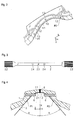
- a brush holder 1 is shown, which is made in the illustrated embodiment of an electrically non-conductive material.
- This brush holder 1 has centrally a concave surface 1.1, which is limited by two webs 1.3 with respect to an x-direction (see also FIGS FIG. 2 ).
- two holes or passages 1.2 are incorporated in the brush holder 1, which extend along a y-direction and penetrate the concave surface 1.1.
- the brush holder 1 also has at its ends in each case a fastening element 1.4, designed here as an open eyelet, and further bores or passages 1.5, which run in a first approximation in the z-direction.
- the brush holder 1 has a central bore 1.6.
- FIG. 3 a brush 2 is shown before it is mounted on the brush holder 1.
- the brush 2 is designed in the form of a comparatively elastic electrically conductive metal strip, wherein the ends are 2.2 slotted.
- a central hole 2.3 and two adjacent holes 2.4 are provided in the central portion of the brush 2.
- the brush 2 is at least between two points P1, P2, at which the brush 2 on the brush holder 1, in particular in the y-direction, supports, elastically biased, so that the brush 2 has a bulge 2.1.
- the brush 2 abuts on the brush holder 1, in particular on the concave surface 1.1.
- the bulge 2.1 of the brush 2 abuts on the brush holder 1, in particular on the concave surface 1.1.
- the brush holder 1, in particular the concave surface 1.1 serves to align the brush 2, in particular for the exact positioning of the free ends 2.2. It is advantageous if the angle ⁇ is set with great accuracy.
- the angle ⁇ is in accordance with FIG. 4 the angle between a central radially oriented (in the direction z) axis and the course of the brush beyond the bulge 2.1, or in the non-prestressed areas on both sides of the bulge 2.1.
- the brush 2 is only elastically deformed, so it has no plastic deformation or resulting structural changes. Therefore, the mechanical properties with respect to the spring action for use in a slip ring assembly are very good.
- an electrically conductive contact element 6 (here in the form of a sleeve 6) through one of the passages 1.2 and a hole 2.4 of the brush 2 is pushed (see FIG. 4 ) and with the brush 2, z. B. electrically contacted by a solder joint.
- strands of electrical wires are then introduced and soldered to the contact elements 6.
- the strands are formed by the passages 1.5 extending substantially in the z-direction (see FIG. 1 ), so that the passages 1.5 also serve as strain relief.
- the guided through the passages 1.5 strands can be potted in the passages 1.5. For clarity, was omitted in the figures on the representation of the strands.
- a slip ring assembly which comprises a plurality of brush units (ie, a plurality of brush holder 1 and brush 2) and in the axial direction x juxtaposed slip rings 3.
- the slip rings 3 are separated by electrically insulating rings 8 at an axial distance from each other, each slip ring 3 has a cylindrical surface area 3.1.
- the slip rings 3 are on its inside against each other electrically isolated on a support tube 7 secured against rotation.
- the lateral surfaces 3.1 are contacted by the brushes 2 electrically.
- the slip rings 3 are contacted with strands for transmitting signals or electrical power.
- FIG. 5 dispensed with the representation of electrical lines.
- the brush holder 1 are fixed with their fasteners 1.4 to brackets 4, in particular by a clip mechanism.
- the brackets 4 are accordingly arranged relative to the circumferential direction of the slip rings 3 on both sides of the bulge 2.1 of the brush 2.
- the slip ring assembly is designed so that the brush holder 1 are lined up in the axial direction x together, so are arranged at an axial distance from each other. This means in particular that there is an axial air gap between adjacent brush holders 1 or adjacent brush units. In this way, the axial positions of the individual brushes 2 relative to the respective associated slip ring 3 can be adjusted individually, so that tolerance-related dimensional deviations can be compensated.
- the presented way of determining the brush holder 1 on the brackets 4 by means of the fastening elements 1.4 is advantageous.
- This determination is frictionally engaged and designed such that with a correspondingly large force introduction a stepless axial displacement for the purpose of a relative axial adjustment of a single brush holder 1 along the brackets 4 of the brush holder 1 along the brackets 4 is displaceable.
- the slip ring assembly is often operated so that the brush unit and the holder 4 are fixed, so are assigned to a stator, while the slip rings 3 and the support tube 7 act as a rotor in contrast.
- the slip ring assembly serves to transfer electrical currents between the rotor and the stator, the rotor and the stator being rotatable relative to one another about an axis A extending in the direction x.
- each of the brushes 2 contacts the lateral surface 3.1 of a slip ring 3 in a grinding manner.
- a slip ring 3 is contacted on its lateral surface 3.1 per brush unit twice by a brush 2, since each brush 2 has two legs, each with a free end 2.2.
- the ends 2.2 are radially movable in the context of the elasticity of the brush 2.
- the webs 1.3 have been provided on the brush holders 1.3, so that a positive axial securing of the brushes 2 is present here.
- This aspect also includes the function according to which the brushes 2 are guided by the webs 1.3 in such a way that they can no longer interlock, in particular their free ends 2.2.
- the brush holder 1 'and the brush 2' no central passage or no central bore.
- the brush 2 ' is initially pressed against the brush holder 1', so that the brush 2 'is elastically deformed and abuts against the concave surface 1.1 of the brush holder 1' .
- an electrically conductive contact element 6 is ever pushed through one of the passages 1.2 and a hole 2.4 of the brush 2 'and with the brush in this phase 2 ', z. B. electrically contacted by a solder joint.
- the electrical contact is used in the second embodiment at the same time as a mechanical attachment.
- the brush 2 ' is elastically prestressed at least between two points P1, P2, at which the brush 2' is supported on the brush holder 1 'and on which the brush 2' is electrically contacted, so that the brush 2 ' has a bulge 2.1.
- the brush 2 ' is also located on the brush holder 1', in particular on the concave surface 1.1.
- the brush 2 ' is not pulled against the concave surface 1.1 by means of an additional fastening means. Rather, the concern of the brush 2 'results in the concave surface 1.1 only from the elastic bias.
- connection of the contact elements 6 to corresponding strands takes place as in the first embodiment.
Landscapes
- Motor Or Generator Current Collectors (AREA)
Priority Applications (4)
| Application Number | Priority Date | Filing Date | Title |
|---|---|---|---|
| EP14000365.8A EP2903103B1 (fr) | 2014-01-31 | 2014-01-31 | Brosse et système de bague collectrice doté d'une brosse |
| DE102014016443.8A DE102014016443A1 (de) | 2014-01-31 | 2014-11-06 | Bürsteneinheit sowie Schleifringanordnung mit einer Bürsteneinheit |
| US14/597,245 US9768573B2 (en) | 2014-01-31 | 2015-01-15 | Brush unit and slip-ring arrangement having a brush unit |
| CN201510050086.3A CN104821473B (zh) | 2014-01-31 | 2015-01-30 | 电刷单元以及具有电刷单元的集电环装置 |
Applications Claiming Priority (1)
| Application Number | Priority Date | Filing Date | Title |
|---|---|---|---|
| EP14000365.8A EP2903103B1 (fr) | 2014-01-31 | 2014-01-31 | Brosse et système de bague collectrice doté d'une brosse |
Publications (2)
| Publication Number | Publication Date |
|---|---|
| EP2903103A1 true EP2903103A1 (fr) | 2015-08-05 |
| EP2903103B1 EP2903103B1 (fr) | 2019-01-02 |
Family
ID=50033320
Family Applications (1)
| Application Number | Title | Priority Date | Filing Date |
|---|---|---|---|
| EP14000365.8A Active EP2903103B1 (fr) | 2014-01-31 | 2014-01-31 | Brosse et système de bague collectrice doté d'une brosse |
Country Status (4)
| Country | Link |
|---|---|
| US (1) | US9768573B2 (fr) |
| EP (1) | EP2903103B1 (fr) |
| CN (1) | CN104821473B (fr) |
| DE (1) | DE102014016443A1 (fr) |
Families Citing this family (9)
| Publication number | Priority date | Publication date | Assignee | Title |
|---|---|---|---|---|
| ITUB20151843A1 (it) * | 2015-07-02 | 2017-01-02 | Conductix Wampfler S R L | Portaspazzole isostatico per collettore elettrico rotante |
| DE102016225984A1 (de) * | 2016-12-22 | 2018-06-28 | Robert Bosch Gmbh | Bürstenhalter für eine elektrische Maschine |
| US20190100275A1 (en) * | 2017-10-03 | 2019-04-04 | PalTorc, Inc. | Smart crank control for e-bike |
| CN108233133A (zh) * | 2017-12-31 | 2018-06-29 | 扬州海通电子科技有限公司 | 模块化触点组件及基于该组件的大型输电滑环触点装置 |
| CN111200225B (zh) * | 2018-11-19 | 2021-05-25 | 杭州海康威视数字技术股份有限公司 | 滑环机构 |
| EP3716415B1 (fr) * | 2019-03-26 | 2021-05-12 | LTN Servotechnik GmbH | Bague collectrice ainsi qu'unité de bague collectrice dotée d'une bague collectrice |
| CN110556681B (zh) * | 2019-08-30 | 2023-04-18 | 上海禾赛科技有限公司 | 一种滑环及激光雷达 |
| IT201900025114A1 (it) * | 2019-12-20 | 2021-06-20 | Spm Special Machine S R L | Dispositivo per condurre corrente elettrica |
| CN111029873B (zh) * | 2019-12-30 | 2022-03-22 | 东莞市马驰科精密制品有限公司 | 导电轴承 |
Citations (5)
| Publication number | Priority date | Publication date | Assignee | Title |
|---|---|---|---|---|
| DE130228C (fr) * | ||||
| DE836970C (de) * | 1950-09-14 | 1952-04-17 | Siemens Ag | Stromabnehmer fuer elektrische Maschinen mit konzentrisch um eine Drehachse gekruemmtem Kontaktstueck, insbesondere Kohlebuerste |
| GB883950A (en) * | 1956-12-24 | 1961-12-06 | Laing Nikolaus | Improvements in or relating to brush holders |
| US4639629A (en) * | 1984-01-13 | 1987-01-27 | Mavilor Systemes S.A. | Brush-holder for flat-commutator electromechanical transducer |
| DE102012204830A1 (de) | 2012-03-26 | 2013-09-26 | Schleifring Und Apparatebau Gmbh | Bürstenblock für eine Schleifringanordnung |
Family Cites Families (7)
| Publication number | Priority date | Publication date | Assignee | Title |
|---|---|---|---|---|
| US2473526A (en) * | 1945-11-19 | 1949-06-21 | Hood Arthur | Slip ring |
| US3398387A (en) * | 1966-03-16 | 1968-08-20 | Litton Prec Products Inc | Inorganic brush and slip-ring assembly |
| DE7010427U (de) * | 1970-03-20 | 1970-11-19 | Siemens Ag | Halterung von schleiffedern an elektrischen drehmeldern und aehnlichen mit schleifringen ausgeruesteten maschinen. |
| US4296345A (en) * | 1980-07-14 | 1981-10-20 | The United States Of America As Represented By The Secretary Of The Navy | Flexible loop slip ring brush |
| EP1453155B1 (fr) * | 2003-02-28 | 2007-03-07 | LTN Servotechnik GmbH | Méthode de production de balais pour bague collectrice et un balai produit par cette méthode |
| DE102006002104A1 (de) * | 2006-01-17 | 2007-07-19 | Ltn Servotechnik Gmbh | Schleifringbürste und damit ausgestattete Schleifringeinheit |
| CN202651584U (zh) * | 2012-04-25 | 2013-01-02 | 北京敬业北低自动化设备有限公司 | 一种单晶炉用集电环电刷 |
-
2014
- 2014-01-31 EP EP14000365.8A patent/EP2903103B1/fr active Active
- 2014-11-06 DE DE102014016443.8A patent/DE102014016443A1/de not_active Withdrawn
-
2015
- 2015-01-15 US US14/597,245 patent/US9768573B2/en active Active
- 2015-01-30 CN CN201510050086.3A patent/CN104821473B/zh active Active
Patent Citations (5)
| Publication number | Priority date | Publication date | Assignee | Title |
|---|---|---|---|---|
| DE130228C (fr) * | ||||
| DE836970C (de) * | 1950-09-14 | 1952-04-17 | Siemens Ag | Stromabnehmer fuer elektrische Maschinen mit konzentrisch um eine Drehachse gekruemmtem Kontaktstueck, insbesondere Kohlebuerste |
| GB883950A (en) * | 1956-12-24 | 1961-12-06 | Laing Nikolaus | Improvements in or relating to brush holders |
| US4639629A (en) * | 1984-01-13 | 1987-01-27 | Mavilor Systemes S.A. | Brush-holder for flat-commutator electromechanical transducer |
| DE102012204830A1 (de) | 2012-03-26 | 2013-09-26 | Schleifring Und Apparatebau Gmbh | Bürstenblock für eine Schleifringanordnung |
Also Published As
| Publication number | Publication date |
|---|---|
| US20150222067A1 (en) | 2015-08-06 |
| DE102014016443A1 (de) | 2015-08-06 |
| EP2903103B1 (fr) | 2019-01-02 |
| US9768573B2 (en) | 2017-09-19 |
| CN104821473A (zh) | 2015-08-05 |
| CN104821473B (zh) | 2018-07-10 |
Similar Documents
| Publication | Publication Date | Title |
|---|---|---|
| EP2903103B1 (fr) | Brosse et système de bague collectrice doté d'une brosse | |
| EP2082472B1 (fr) | Moteur électrique | |
| EP1808941B1 (fr) | Balais pour bague collectrice et dispositif de bague collectrice le contenant | |
| EP3378128B1 (fr) | Arrangement avec un élément de contact et un câble électrique et méthode pour la production d'un tel arrangement | |
| EP1804339B1 (fr) | Connexion électrique | |
| DE102013001836B3 (de) | Überfeder und Steckverbinder mit einer Überfeder | |
| DE10110067A1 (de) | Lager mit einer elektrisch leitfähigen Verbindung zwischen den Lagerringen | |
| EP3118946B1 (fr) | Collecteur rotatif et unité comprenant un collecteur rotatif | |
| DE102012201124B4 (de) | Kontaktelement | |
| EP2200125B1 (fr) | Connecteur à fiches blindé | |
| DE102013204004B4 (de) | Schleifringbürsten in Blindniettechnik und Halterung | |
| DE102008058203A1 (de) | Steckbuchse für Leiterplatten | |
| DE3408432A1 (de) | Fuer eine elektrische steckkontaktvorrichtung vorgesehenes kontaktstueck | |
| DE102016116375B4 (de) | Kontaktierungsvorrichtung | |
| EP2065982B1 (fr) | Elément de raccordement électrique | |
| EP3182529B1 (fr) | Bague collectrice | |
| DE102013201689A1 (de) | Schirmgehäuse | |
| DE2041110A1 (de) | Befestigungsvorrichtung zum Befestigen der aeusseren Enden zweier Spiralfedern in zeithaltenden Instrumenten | |
| DE102009057944B3 (de) | Kontaktbuchse zur Aufnahme eines Kontaktstiftes | |
| DD230107A1 (de) | Steckbare kontaktanordnung | |
| DE2400751C3 (de) | Elektrischer Drehschalter mit einem Isolierstoffrotor zur federnden Aufnahme mindestens einer starren Kontaktbrücke | |
| DE10251348B4 (de) | Kontaktstift zur elektrischen und mechanischen Verbindung mit einem Anschlusselement | |
| DE2262393C3 (de) | Stromführende Verbindung zwischen elektrischen Leitern in einer Flanschkupplung | |
| EP1054495A1 (fr) | Section de conduit à isolation par gaz et procédé de sa fabrication | |
| DE102016012216A1 (de) | Batterieklemme zur Herstellung eines elektrischen Kontakts zu einem Pol einer Batterie und Verfahren zur Herstellung einer Batterieklemme |
Legal Events
| Date | Code | Title | Description |
|---|---|---|---|
| PUAI | Public reference made under article 153(3) epc to a published international application that has entered the european phase |
Free format text: ORIGINAL CODE: 0009012 |
|
| 17P | Request for examination filed |
Effective date: 20140131 |
|
| AK | Designated contracting states |
Kind code of ref document: A1 Designated state(s): AL AT BE BG CH CY CZ DE DK EE ES FI FR GB GR HR HU IE IS IT LI LT LU LV MC MK MT NL NO PL PT RO RS SE SI SK SM TR |
|
| AX | Request for extension of the european patent |
Extension state: BA ME |
|
| RBV | Designated contracting states (corrected) |
Designated state(s): AL AT BE BG CH CY CZ DE DK EE ES FI FR GB GR HR HU IE IS IT LI LT LU LV MC MK MT NL NO PL PT RO RS SE SI SK SM TR |
|
| STAA | Information on the status of an ep patent application or granted ep patent |
Free format text: STATUS: EXAMINATION IS IN PROGRESS |
|
| REG | Reference to a national code |
Ref country code: DE Ref legal event code: R079 Ref document number: 502014010503 Country of ref document: DE Free format text: PREVIOUS MAIN CLASS: H01R0039380000 Ipc: H01R0039080000 |
|
| GRAP | Despatch of communication of intention to grant a patent |
Free format text: ORIGINAL CODE: EPIDOSNIGR1 |
|
| STAA | Information on the status of an ep patent application or granted ep patent |
Free format text: STATUS: GRANT OF PATENT IS INTENDED |
|
| RIC1 | Information provided on ipc code assigned before grant |
Ipc: H01R 39/38 20060101ALI20180823BHEP Ipc: H01R 39/39 20060101ALI20180823BHEP Ipc: H01R 39/08 20060101AFI20180823BHEP |
|
| INTG | Intention to grant announced |
Effective date: 20180919 |
|
| GRAS | Grant fee paid |
Free format text: ORIGINAL CODE: EPIDOSNIGR3 |
|
| GRAA | (expected) grant |
Free format text: ORIGINAL CODE: 0009210 |
|
| STAA | Information on the status of an ep patent application or granted ep patent |
Free format text: STATUS: THE PATENT HAS BEEN GRANTED |
|
| AK | Designated contracting states |
Kind code of ref document: B1 Designated state(s): AL AT BE BG CH CY CZ DE DK EE ES FI FR GB GR HR HU IE IS IT LI LT LU LV MC MK MT NL NO PL PT RO RS SE SI SK SM TR |
|
| REG | Reference to a national code |
Ref country code: GB Ref legal event code: FG4D Free format text: NOT ENGLISH |
|
| REG | Reference to a national code |
Ref country code: CH Ref legal event code: EP Ref country code: AT Ref legal event code: REF Ref document number: 1085612 Country of ref document: AT Kind code of ref document: T Effective date: 20190115 |
|
| REG | Reference to a national code |
Ref country code: DE Ref legal event code: R096 Ref document number: 502014010503 Country of ref document: DE |
|
| REG | Reference to a national code |
Ref country code: IE Ref legal event code: FG4D Free format text: LANGUAGE OF EP DOCUMENT: GERMAN |
|
| REG | Reference to a national code |
Ref country code: NL Ref legal event code: MP Effective date: 20190102 |
|
| REG | Reference to a national code |
Ref country code: LT Ref legal event code: MG4D |
|
| PG25 | Lapsed in a contracting state [announced via postgrant information from national office to epo] |
Ref country code: NL Free format text: LAPSE BECAUSE OF FAILURE TO SUBMIT A TRANSLATION OF THE DESCRIPTION OR TO PAY THE FEE WITHIN THE PRESCRIBED TIME-LIMIT Effective date: 20190102 |
|
| PG25 | Lapsed in a contracting state [announced via postgrant information from national office to epo] |
Ref country code: PL Free format text: LAPSE BECAUSE OF FAILURE TO SUBMIT A TRANSLATION OF THE DESCRIPTION OR TO PAY THE FEE WITHIN THE PRESCRIBED TIME-LIMIT Effective date: 20190102 Ref country code: LT Free format text: LAPSE BECAUSE OF FAILURE TO SUBMIT A TRANSLATION OF THE DESCRIPTION OR TO PAY THE FEE WITHIN THE PRESCRIBED TIME-LIMIT Effective date: 20190102 Ref country code: SE Free format text: LAPSE BECAUSE OF FAILURE TO SUBMIT A TRANSLATION OF THE DESCRIPTION OR TO PAY THE FEE WITHIN THE PRESCRIBED TIME-LIMIT Effective date: 20190102 Ref country code: NO Free format text: LAPSE BECAUSE OF FAILURE TO SUBMIT A TRANSLATION OF THE DESCRIPTION OR TO PAY THE FEE WITHIN THE PRESCRIBED TIME-LIMIT Effective date: 20190402 Ref country code: ES Free format text: LAPSE BECAUSE OF FAILURE TO SUBMIT A TRANSLATION OF THE DESCRIPTION OR TO PAY THE FEE WITHIN THE PRESCRIBED TIME-LIMIT Effective date: 20190102 Ref country code: PT Free format text: LAPSE BECAUSE OF FAILURE TO SUBMIT A TRANSLATION OF THE DESCRIPTION OR TO PAY THE FEE WITHIN THE PRESCRIBED TIME-LIMIT Effective date: 20190502 Ref country code: FI Free format text: LAPSE BECAUSE OF FAILURE TO SUBMIT A TRANSLATION OF THE DESCRIPTION OR TO PAY THE FEE WITHIN THE PRESCRIBED TIME-LIMIT Effective date: 20190102 |
|
| PG25 | Lapsed in a contracting state [announced via postgrant information from national office to epo] |
Ref country code: BG Free format text: LAPSE BECAUSE OF FAILURE TO SUBMIT A TRANSLATION OF THE DESCRIPTION OR TO PAY THE FEE WITHIN THE PRESCRIBED TIME-LIMIT Effective date: 20190402 Ref country code: RS Free format text: LAPSE BECAUSE OF FAILURE TO SUBMIT A TRANSLATION OF THE DESCRIPTION OR TO PAY THE FEE WITHIN THE PRESCRIBED TIME-LIMIT Effective date: 20190102 Ref country code: LV Free format text: LAPSE BECAUSE OF FAILURE TO SUBMIT A TRANSLATION OF THE DESCRIPTION OR TO PAY THE FEE WITHIN THE PRESCRIBED TIME-LIMIT Effective date: 20190102 Ref country code: IS Free format text: LAPSE BECAUSE OF FAILURE TO SUBMIT A TRANSLATION OF THE DESCRIPTION OR TO PAY THE FEE WITHIN THE PRESCRIBED TIME-LIMIT Effective date: 20190502 Ref country code: GR Free format text: LAPSE BECAUSE OF FAILURE TO SUBMIT A TRANSLATION OF THE DESCRIPTION OR TO PAY THE FEE WITHIN THE PRESCRIBED TIME-LIMIT Effective date: 20190403 Ref country code: HR Free format text: LAPSE BECAUSE OF FAILURE TO SUBMIT A TRANSLATION OF THE DESCRIPTION OR TO PAY THE FEE WITHIN THE PRESCRIBED TIME-LIMIT Effective date: 20190102 |
|
| REG | Reference to a national code |
Ref country code: CH Ref legal event code: PL |
|
| PG25 | Lapsed in a contracting state [announced via postgrant information from national office to epo] |
Ref country code: LU Free format text: LAPSE BECAUSE OF NON-PAYMENT OF DUE FEES Effective date: 20190131 |
|
| REG | Reference to a national code |
Ref country code: DE Ref legal event code: R097 Ref document number: 502014010503 Country of ref document: DE |
|
| REG | Reference to a national code |
Ref country code: BE Ref legal event code: MM Effective date: 20190131 |
|
| REG | Reference to a national code |
Ref country code: IE Ref legal event code: MM4A |
|
| PG25 | Lapsed in a contracting state [announced via postgrant information from national office to epo] |
Ref country code: MC Free format text: LAPSE BECAUSE OF FAILURE TO SUBMIT A TRANSLATION OF THE DESCRIPTION OR TO PAY THE FEE WITHIN THE PRESCRIBED TIME-LIMIT Effective date: 20190102 Ref country code: DK Free format text: LAPSE BECAUSE OF FAILURE TO SUBMIT A TRANSLATION OF THE DESCRIPTION OR TO PAY THE FEE WITHIN THE PRESCRIBED TIME-LIMIT Effective date: 20190102 Ref country code: SK Free format text: LAPSE BECAUSE OF FAILURE TO SUBMIT A TRANSLATION OF THE DESCRIPTION OR TO PAY THE FEE WITHIN THE PRESCRIBED TIME-LIMIT Effective date: 20190102 Ref country code: AL Free format text: LAPSE BECAUSE OF FAILURE TO SUBMIT A TRANSLATION OF THE DESCRIPTION OR TO PAY THE FEE WITHIN THE PRESCRIBED TIME-LIMIT Effective date: 20190102 Ref country code: EE Free format text: LAPSE BECAUSE OF FAILURE TO SUBMIT A TRANSLATION OF THE DESCRIPTION OR TO PAY THE FEE WITHIN THE PRESCRIBED TIME-LIMIT Effective date: 20190102 Ref country code: IT Free format text: LAPSE BECAUSE OF FAILURE TO SUBMIT A TRANSLATION OF THE DESCRIPTION OR TO PAY THE FEE WITHIN THE PRESCRIBED TIME-LIMIT Effective date: 20190102 Ref country code: CZ Free format text: LAPSE BECAUSE OF FAILURE TO SUBMIT A TRANSLATION OF THE DESCRIPTION OR TO PAY THE FEE WITHIN THE PRESCRIBED TIME-LIMIT Effective date: 20190102 Ref country code: RO Free format text: LAPSE BECAUSE OF FAILURE TO SUBMIT A TRANSLATION OF THE DESCRIPTION OR TO PAY THE FEE WITHIN THE PRESCRIBED TIME-LIMIT Effective date: 20190102 |
|
| PLBE | No opposition filed within time limit |
Free format text: ORIGINAL CODE: 0009261 |
|
| STAA | Information on the status of an ep patent application or granted ep patent |
Free format text: STATUS: NO OPPOSITION FILED WITHIN TIME LIMIT |
|
| PG25 | Lapsed in a contracting state [announced via postgrant information from national office to epo] |
Ref country code: BE Free format text: LAPSE BECAUSE OF NON-PAYMENT OF DUE FEES Effective date: 20190131 Ref country code: SM Free format text: LAPSE BECAUSE OF FAILURE TO SUBMIT A TRANSLATION OF THE DESCRIPTION OR TO PAY THE FEE WITHIN THE PRESCRIBED TIME-LIMIT Effective date: 20190102 |
|
| 26N | No opposition filed |
Effective date: 20191003 |
|
| GBPC | Gb: european patent ceased through non-payment of renewal fee |
Effective date: 20190402 |
|
| PG25 | Lapsed in a contracting state [announced via postgrant information from national office to epo] |
Ref country code: LI Free format text: LAPSE BECAUSE OF NON-PAYMENT OF DUE FEES Effective date: 20190131 Ref country code: CH Free format text: LAPSE BECAUSE OF NON-PAYMENT OF DUE FEES Effective date: 20190131 |
|
| PG25 | Lapsed in a contracting state [announced via postgrant information from national office to epo] |
Ref country code: GB Free format text: LAPSE BECAUSE OF NON-PAYMENT OF DUE FEES Effective date: 20190402 Ref country code: IE Free format text: LAPSE BECAUSE OF NON-PAYMENT OF DUE FEES Effective date: 20190131 |
|
| PG25 | Lapsed in a contracting state [announced via postgrant information from national office to epo] |
Ref country code: FR Free format text: LAPSE BECAUSE OF NON-PAYMENT OF DUE FEES Effective date: 20190302 Ref country code: SI Free format text: LAPSE BECAUSE OF FAILURE TO SUBMIT A TRANSLATION OF THE DESCRIPTION OR TO PAY THE FEE WITHIN THE PRESCRIBED TIME-LIMIT Effective date: 20190102 |
|
| REG | Reference to a national code |
Ref country code: AT Ref legal event code: MM01 Ref document number: 1085612 Country of ref document: AT Kind code of ref document: T Effective date: 20190131 |
|
| PG25 | Lapsed in a contracting state [announced via postgrant information from national office to epo] |
Ref country code: TR Free format text: LAPSE BECAUSE OF FAILURE TO SUBMIT A TRANSLATION OF THE DESCRIPTION OR TO PAY THE FEE WITHIN THE PRESCRIBED TIME-LIMIT Effective date: 20190102 |
|
| PG25 | Lapsed in a contracting state [announced via postgrant information from national office to epo] |
Ref country code: AT Free format text: LAPSE BECAUSE OF NON-PAYMENT OF DUE FEES Effective date: 20190131 |
|
| PG25 | Lapsed in a contracting state [announced via postgrant information from national office to epo] |
Ref country code: MT Free format text: LAPSE BECAUSE OF FAILURE TO SUBMIT A TRANSLATION OF THE DESCRIPTION OR TO PAY THE FEE WITHIN THE PRESCRIBED TIME-LIMIT Effective date: 20190102 |
|
| PG25 | Lapsed in a contracting state [announced via postgrant information from national office to epo] |
Ref country code: CY Free format text: LAPSE BECAUSE OF FAILURE TO SUBMIT A TRANSLATION OF THE DESCRIPTION OR TO PAY THE FEE WITHIN THE PRESCRIBED TIME-LIMIT Effective date: 20190102 |
|
| PG25 | Lapsed in a contracting state [announced via postgrant information from national office to epo] |
Ref country code: HU Free format text: LAPSE BECAUSE OF FAILURE TO SUBMIT A TRANSLATION OF THE DESCRIPTION OR TO PAY THE FEE WITHIN THE PRESCRIBED TIME-LIMIT; INVALID AB INITIO Effective date: 20140131 |
|
| PG25 | Lapsed in a contracting state [announced via postgrant information from national office to epo] |
Ref country code: MK Free format text: LAPSE BECAUSE OF FAILURE TO SUBMIT A TRANSLATION OF THE DESCRIPTION OR TO PAY THE FEE WITHIN THE PRESCRIBED TIME-LIMIT Effective date: 20190102 |
|
| PGFP | Annual fee paid to national office [announced via postgrant information from national office to epo] |
Ref country code: DE Payment date: 20240119 Year of fee payment: 11 |