EP2902855A2 - Watch external part, manufacturing method for watch external part, and watch - Google Patents
Watch external part, manufacturing method for watch external part, and watch Download PDFInfo
- Publication number
- EP2902855A2 EP2902855A2 EP15152827.0A EP15152827A EP2902855A2 EP 2902855 A2 EP2902855 A2 EP 2902855A2 EP 15152827 A EP15152827 A EP 15152827A EP 2902855 A2 EP2902855 A2 EP 2902855A2
- Authority
- EP
- European Patent Office
- Prior art keywords
- coating
- watch
- external part
- watch external
- substrate
- Prior art date
- Legal status (The legal status is an assumption and is not a legal conclusion. Google has not performed a legal analysis and makes no representation as to the accuracy of the status listed.)
- Withdrawn
Links
- 238000004519 manufacturing process Methods 0.000 title claims description 34
- 239000011248 coating agent Substances 0.000 claims abstract description 140
- 238000000576 coating method Methods 0.000 claims abstract description 140
- 239000000443 aerosol Substances 0.000 claims abstract description 78
- 239000000758 substrate Substances 0.000 claims abstract description 74
- 239000000463 material Substances 0.000 claims abstract description 38
- 238000000151 deposition Methods 0.000 claims abstract description 21
- 239000011521 glass Substances 0.000 claims abstract description 13
- VYPSYNLAJGMNEJ-UHFFFAOYSA-N silicon dioxide Inorganic materials O=[Si]=O VYPSYNLAJGMNEJ-UHFFFAOYSA-N 0.000 claims abstract description 10
- 239000004033 plastic Substances 0.000 claims abstract description 6
- 239000010453 quartz Substances 0.000 claims abstract description 6
- 239000010980 sapphire Substances 0.000 claims abstract description 5
- 229910052594 sapphire Inorganic materials 0.000 claims abstract description 5
- 239000006117 anti-reflective coating Substances 0.000 claims description 18
- 238000000034 method Methods 0.000 claims description 12
- 239000007769 metal material Substances 0.000 claims description 11
- 229910052751 metal Inorganic materials 0.000 claims description 9
- 239000002184 metal Substances 0.000 claims description 9
- 229910044991 metal oxide Inorganic materials 0.000 claims description 8
- 150000004706 metal oxides Chemical class 0.000 claims description 8
- 150000004767 nitrides Chemical class 0.000 claims description 7
- ATJFFYVFTNAWJD-UHFFFAOYSA-N Tin Chemical compound [Sn] ATJFFYVFTNAWJD-UHFFFAOYSA-N 0.000 claims description 4
- 230000008878 coupling Effects 0.000 description 40
- 238000010168 coupling process Methods 0.000 description 40
- 238000005859 coupling reaction Methods 0.000 description 40
- 239000010408 film Substances 0.000 description 33
- 239000002245 particle Substances 0.000 description 32
- 239000007789 gas Substances 0.000 description 31
- 230000006870 function Effects 0.000 description 20
- 230000000694 effects Effects 0.000 description 13
- 230000015572 biosynthetic process Effects 0.000 description 11
- 239000002699 waste material Substances 0.000 description 11
- 238000004804 winding Methods 0.000 description 11
- 239000006059 cover glass Substances 0.000 description 10
- 239000000203 mixture Substances 0.000 description 10
- 238000012856 packing Methods 0.000 description 8
- 239000011164 primary particle Substances 0.000 description 7
- 238000012545 processing Methods 0.000 description 7
- OKTJSMMVPCPJKN-UHFFFAOYSA-N Carbon Chemical compound [C] OKTJSMMVPCPJKN-UHFFFAOYSA-N 0.000 description 6
- 238000010586 diagram Methods 0.000 description 5
- 238000010438 heat treatment Methods 0.000 description 5
- 230000007246 mechanism Effects 0.000 description 5
- UQSXHKLRYXJYBZ-UHFFFAOYSA-N Iron oxide Chemical compound [Fe]=O UQSXHKLRYXJYBZ-UHFFFAOYSA-N 0.000 description 4
- XUIMIQQOPSSXEZ-UHFFFAOYSA-N Silicon Chemical compound [Si] XUIMIQQOPSSXEZ-UHFFFAOYSA-N 0.000 description 4
- 238000005229 chemical vapour deposition Methods 0.000 description 4
- 238000004891 communication Methods 0.000 description 4
- QDOXWKRWXJOMAK-UHFFFAOYSA-N dichromium trioxide Chemical compound O=[Cr]O[Cr]=O QDOXWKRWXJOMAK-UHFFFAOYSA-N 0.000 description 4
- 239000010419 fine particle Substances 0.000 description 4
- 238000007747 plating Methods 0.000 description 4
- 229910052710 silicon Inorganic materials 0.000 description 4
- 239000010703 silicon Substances 0.000 description 4
- 239000010409 thin film Substances 0.000 description 4
- GWEVSGVZZGPLCZ-UHFFFAOYSA-N Titan oxide Chemical compound O=[Ti]=O GWEVSGVZZGPLCZ-UHFFFAOYSA-N 0.000 description 3
- -1 chrome nitride Chemical class 0.000 description 3
- 238000004140 cleaning Methods 0.000 description 3
- 230000008021 deposition Effects 0.000 description 3
- 230000001747 exhibiting effect Effects 0.000 description 3
- 230000004313 glare Effects 0.000 description 3
- 239000012535 impurity Substances 0.000 description 3
- MOUPNEIJQCETIW-UHFFFAOYSA-N lead chromate Chemical compound [Pb+2].[O-][Cr]([O-])(=O)=O MOUPNEIJQCETIW-UHFFFAOYSA-N 0.000 description 3
- 239000000049 pigment Substances 0.000 description 3
- OGIDPMRJRNCKJF-UHFFFAOYSA-N titanium oxide Inorganic materials [Ti]=O OGIDPMRJRNCKJF-UHFFFAOYSA-N 0.000 description 3
- 238000007740 vapor deposition Methods 0.000 description 3
- 239000012808 vapor phase Substances 0.000 description 3
- OSNILPMOSNGHLC-UHFFFAOYSA-N 1-[4-methoxy-3-(piperidin-1-ylmethyl)phenyl]ethanone Chemical compound COC1=CC=C(C(C)=O)C=C1CN1CCCCC1 OSNILPMOSNGHLC-UHFFFAOYSA-N 0.000 description 2
- IICCLYANAQEHCI-UHFFFAOYSA-N 4,5,6,7-tetrachloro-3',6'-dihydroxy-2',4',5',7'-tetraiodospiro[2-benzofuran-3,9'-xanthene]-1-one Chemical compound O1C(=O)C(C(=C(Cl)C(Cl)=C2Cl)Cl)=C2C21C1=CC(I)=C(O)C(I)=C1OC1=C(I)C(O)=C(I)C=C21 IICCLYANAQEHCI-UHFFFAOYSA-N 0.000 description 2
- XKRFYHLGVUSROY-UHFFFAOYSA-N Argon Chemical compound [Ar] XKRFYHLGVUSROY-UHFFFAOYSA-N 0.000 description 2
- XLOMVQKBTHCTTD-UHFFFAOYSA-N Zinc monoxide Chemical compound [Zn]=O XLOMVQKBTHCTTD-UHFFFAOYSA-N 0.000 description 2
- RGCKGOZRHPZPFP-UHFFFAOYSA-N alizarin Chemical compound C1=CC=C2C(=O)C3=C(O)C(O)=CC=C3C(=O)C2=C1 RGCKGOZRHPZPFP-UHFFFAOYSA-N 0.000 description 2
- IRERQBUNZFJFGC-UHFFFAOYSA-L azure blue Chemical compound [Na+].[Na+].[Na+].[Na+].[Na+].[Na+].[Na+].[Na+].[Al+3].[Al+3].[Al+3].[Al+3].[Al+3].[Al+3].[S-]S[S-].[O-][Si]([O-])([O-])[O-].[O-][Si]([O-])([O-])[O-].[O-][Si]([O-])([O-])[O-].[O-][Si]([O-])([O-])[O-].[O-][Si]([O-])([O-])[O-].[O-][Si]([O-])([O-])[O-] IRERQBUNZFJFGC-UHFFFAOYSA-L 0.000 description 2
- 239000012159 carrier gas Substances 0.000 description 2
- 239000003086 colorant Substances 0.000 description 2
- 238000007598 dipping method Methods 0.000 description 2
- 239000000975 dye Substances 0.000 description 2
- 238000007733 ion plating Methods 0.000 description 2
- NUJOXMJBOLGQSY-UHFFFAOYSA-N manganese dioxide Chemical compound O=[Mn]=O NUJOXMJBOLGQSY-UHFFFAOYSA-N 0.000 description 2
- CXKWCBBOMKCUKX-UHFFFAOYSA-M methylene blue Chemical compound [Cl-].C1=CC(N(C)C)=CC2=[S+]C3=CC(N(C)C)=CC=C3N=C21 CXKWCBBOMKCUKX-UHFFFAOYSA-M 0.000 description 2
- 239000003921 oil Substances 0.000 description 2
- 239000000843 powder Substances 0.000 description 2
- 238000002360 preparation method Methods 0.000 description 2
- 235000012752 quinoline yellow Nutrition 0.000 description 2
- 229940051201 quinoline yellow Drugs 0.000 description 2
- IZMJMCDDWKSTTK-UHFFFAOYSA-N quinoline yellow Chemical compound C1=CC=CC2=NC(C3C(C4=CC=CC=C4C3=O)=O)=CC=C21 IZMJMCDDWKSTTK-UHFFFAOYSA-N 0.000 description 2
- 239000004172 quinoline yellow Substances 0.000 description 2
- 229940081623 rose bengal Drugs 0.000 description 2
- 229930187593 rose bengal Natural products 0.000 description 2
- STRXNPAVPKGJQR-UHFFFAOYSA-N rose bengal A Natural products O1C(=O)C(C(=CC=C2Cl)Cl)=C2C21C1=CC(I)=C(O)C(I)=C1OC1=C(I)C(O)=C(I)C=C21 STRXNPAVPKGJQR-UHFFFAOYSA-N 0.000 description 2
- 239000004065 semiconductor Substances 0.000 description 2
- 238000004544 sputter deposition Methods 0.000 description 2
- 239000010935 stainless steel Substances 0.000 description 2
- 229910001220 stainless steel Inorganic materials 0.000 description 2
- 238000003860 storage Methods 0.000 description 2
- 239000000126 substance Substances 0.000 description 2
- 238000002834 transmittance Methods 0.000 description 2
- 235000013799 ultramarine blue Nutrition 0.000 description 2
- 238000004078 waterproofing Methods 0.000 description 2
- FWLHAQYOFMQTHQ-UHFFFAOYSA-N 2-N-[8-[[8-(4-aminoanilino)-10-phenylphenazin-10-ium-2-yl]amino]-10-phenylphenazin-10-ium-2-yl]-8-N,10-diphenylphenazin-10-ium-2,8-diamine hydroxy-oxido-dioxochromium Chemical compound O[Cr]([O-])(=O)=O.O[Cr]([O-])(=O)=O.O[Cr]([O-])(=O)=O.Nc1ccc(Nc2ccc3nc4ccc(Nc5ccc6nc7ccc(Nc8ccc9nc%10ccc(Nc%11ccccc%11)cc%10[n+](-c%10ccccc%10)c9c8)cc7[n+](-c7ccccc7)c6c5)cc4[n+](-c4ccccc4)c3c2)cc1 FWLHAQYOFMQTHQ-UHFFFAOYSA-N 0.000 description 1
- JFMYRCRXYIIGBB-UHFFFAOYSA-N 2-[(2,4-dichlorophenyl)diazenyl]-n-[4-[4-[[2-[(2,4-dichlorophenyl)diazenyl]-3-oxobutanoyl]amino]-3-methylphenyl]-2-methylphenyl]-3-oxobutanamide Chemical compound C=1C=C(C=2C=C(C)C(NC(=O)C(N=NC=3C(=CC(Cl)=CC=3)Cl)C(C)=O)=CC=2)C=C(C)C=1NC(=O)C(C(=O)C)N=NC1=CC=C(Cl)C=C1Cl JFMYRCRXYIIGBB-UHFFFAOYSA-N 0.000 description 1
- QTSNFLIDNYOATQ-UHFFFAOYSA-N 2-[(4-chloro-2-nitrophenyl)diazenyl]-n-(2-chlorophenyl)-3-oxobutanamide Chemical compound C=1C=CC=C(Cl)C=1NC(=O)C(C(=O)C)N=NC1=CC=C(Cl)C=C1[N+]([O-])=O QTSNFLIDNYOATQ-UHFFFAOYSA-N 0.000 description 1
- MFYSUUPKMDJYPF-UHFFFAOYSA-N 2-[(4-methyl-2-nitrophenyl)diazenyl]-3-oxo-n-phenylbutanamide Chemical compound C=1C=CC=CC=1NC(=O)C(C(=O)C)N=NC1=CC=C(C)C=C1[N+]([O-])=O MFYSUUPKMDJYPF-UHFFFAOYSA-N 0.000 description 1
- DWDURZSYQTXVIN-UHFFFAOYSA-N 4-[(4-aminophenyl)-(4-methyliminocyclohexa-2,5-dien-1-ylidene)methyl]aniline Chemical compound C1=CC(=NC)C=CC1=C(C=1C=CC(N)=CC=1)C1=CC=C(N)C=C1 DWDURZSYQTXVIN-UHFFFAOYSA-N 0.000 description 1
- LVOJOIBIVGEQBP-UHFFFAOYSA-N 4-[[2-chloro-4-[3-chloro-4-[(5-hydroxy-3-methyl-1-phenylpyrazol-4-yl)diazenyl]phenyl]phenyl]diazenyl]-5-methyl-2-phenylpyrazol-3-ol Chemical compound CC1=NN(C(O)=C1N=NC1=CC=C(C=C1Cl)C1=CC(Cl)=C(C=C1)N=NC1=C(O)N(N=C1C)C1=CC=CC=C1)C1=CC=CC=C1 LVOJOIBIVGEQBP-UHFFFAOYSA-N 0.000 description 1
- IYHIFXGFKVJNBB-UHFFFAOYSA-N 5-chloro-2-[(2-hydroxynaphthalen-1-yl)diazenyl]-4-methylbenzenesulfonic acid Chemical compound C1=C(Cl)C(C)=CC(N=NC=2C3=CC=CC=C3C=CC=2O)=C1S(O)(=O)=O IYHIFXGFKVJNBB-UHFFFAOYSA-N 0.000 description 1
- IJGRMHOSHXDMSA-UHFFFAOYSA-N Atomic nitrogen Chemical compound N#N IJGRMHOSHXDMSA-UHFFFAOYSA-N 0.000 description 1
- REEFSLKDEDEWAO-UHFFFAOYSA-N Chloraniformethan Chemical compound ClC1=CC=C(NC(NC=O)C(Cl)(Cl)Cl)C=C1Cl REEFSLKDEDEWAO-UHFFFAOYSA-N 0.000 description 1
- QPLDLSVMHZLSFG-UHFFFAOYSA-N Copper oxide Chemical compound [Cu]=O QPLDLSVMHZLSFG-UHFFFAOYSA-N 0.000 description 1
- 239000005751 Copper oxide Substances 0.000 description 1
- PEDCQBHIVMGVHV-UHFFFAOYSA-N Glycerine Chemical compound OCC(O)CO PEDCQBHIVMGVHV-UHFFFAOYSA-N 0.000 description 1
- HBBGRARXTFLTSG-UHFFFAOYSA-N Lithium ion Chemical compound [Li+] HBBGRARXTFLTSG-UHFFFAOYSA-N 0.000 description 1
- 241001676573 Minium Species 0.000 description 1
- 229910052581 Si3N4 Inorganic materials 0.000 description 1
- NRTOMJZYCJJWKI-UHFFFAOYSA-N Titanium nitride Chemical compound [Ti]#N NRTOMJZYCJJWKI-UHFFFAOYSA-N 0.000 description 1
- 239000005083 Zinc sulfide Substances 0.000 description 1
- AUNAPVYQLLNFOI-UHFFFAOYSA-L [Pb++].[Pb++].[Pb++].[O-]S([O-])(=O)=O.[O-][Cr]([O-])(=O)=O.[O-][Mo]([O-])(=O)=O Chemical compound [Pb++].[Pb++].[Pb++].[O-]S([O-])(=O)=O.[O-][Cr]([O-])(=O)=O.[O-][Mo]([O-])(=O)=O AUNAPVYQLLNFOI-UHFFFAOYSA-L 0.000 description 1
- 239000006230 acetylene black Substances 0.000 description 1
- 239000002253 acid Substances 0.000 description 1
- 230000002378 acidificating effect Effects 0.000 description 1
- 230000002411 adverse Effects 0.000 description 1
- 238000005054 agglomeration Methods 0.000 description 1
- AOADSHDCARXSGL-ZMIIQOOPSA-M alkali blue 4B Chemical compound CC1=CC(/C(\C(C=C2)=CC=C2NC2=CC=CC=C2S([O-])(=O)=O)=C(\C=C2)/C=C/C\2=N\C2=CC=CC=C2)=CC=C1N.[Na+] AOADSHDCARXSGL-ZMIIQOOPSA-M 0.000 description 1
- 229910045601 alloy Inorganic materials 0.000 description 1
- 239000000956 alloy Substances 0.000 description 1
- 229910052782 aluminium Inorganic materials 0.000 description 1
- PNEYBMLMFCGWSK-UHFFFAOYSA-N aluminium oxide Inorganic materials [O-2].[O-2].[O-2].[Al+3].[Al+3] PNEYBMLMFCGWSK-UHFFFAOYSA-N 0.000 description 1
- GHPGOEFPKIHBNM-UHFFFAOYSA-N antimony(3+);oxygen(2-) Chemical compound [O-2].[O-2].[O-2].[Sb+3].[Sb+3] GHPGOEFPKIHBNM-UHFFFAOYSA-N 0.000 description 1
- 229910052786 argon Inorganic materials 0.000 description 1
- QVGXLLKOCUKJST-UHFFFAOYSA-N atomic oxygen Chemical compound [O] QVGXLLKOCUKJST-UHFFFAOYSA-N 0.000 description 1
- UHHXUPJJDHEMGX-UHFFFAOYSA-K azanium;manganese(3+);phosphonato phosphate Chemical compound [NH4+].[Mn+3].[O-]P([O-])(=O)OP([O-])([O-])=O UHHXUPJJDHEMGX-UHFFFAOYSA-K 0.000 description 1
- QVQLCTNNEUAWMS-UHFFFAOYSA-N barium oxide Chemical compound [Ba]=O QVQLCTNNEUAWMS-UHFFFAOYSA-N 0.000 description 1
- AYJRCSIUFZENHW-DEQYMQKBSA-L barium(2+);oxomethanediolate Chemical compound [Ba+2].[O-][14C]([O-])=O AYJRCSIUFZENHW-DEQYMQKBSA-L 0.000 description 1
- 229910001864 baryta Inorganic materials 0.000 description 1
- 239000002585 base Substances 0.000 description 1
- 230000005540 biological transmission Effects 0.000 description 1
- 239000001055 blue pigment Substances 0.000 description 1
- 229910052793 cadmium Inorganic materials 0.000 description 1
- BDOSMKKIYDKNTQ-UHFFFAOYSA-N cadmium atom Chemical compound [Cd] BDOSMKKIYDKNTQ-UHFFFAOYSA-N 0.000 description 1
- CJOBVZJTOIVNNF-UHFFFAOYSA-N cadmium sulfide Chemical compound [Cd]=S CJOBVZJTOIVNNF-UHFFFAOYSA-N 0.000 description 1
- 239000003990 capacitor Substances 0.000 description 1
- 239000006229 carbon black Substances 0.000 description 1
- 235000019241 carbon black Nutrition 0.000 description 1
- 239000003575 carbonaceous material Substances 0.000 description 1
- 230000008859 change Effects 0.000 description 1
- 239000006231 channel black Substances 0.000 description 1
- HBHZKFOUIUMKHV-UHFFFAOYSA-N chembl1982121 Chemical compound OC1=CC=C2C=CC=CC2=C1N=NC1=CC=C([N+]([O-])=O)C=C1[N+]([O-])=O HBHZKFOUIUMKHV-UHFFFAOYSA-N 0.000 description 1
- GTRGJJDVSJFNTE-UHFFFAOYSA-N chembl2009633 Chemical compound OC1=CC=C2C=C(S(O)(=O)=O)C=CC2=C1N=NC1=CC=CC=C1 GTRGJJDVSJFNTE-UHFFFAOYSA-N 0.000 description 1
- PZTQVMXMKVTIRC-UHFFFAOYSA-L chembl2028348 Chemical compound [Ca+2].[O-]S(=O)(=O)C1=CC(C)=CC=C1N=NC1=C(O)C(C([O-])=O)=CC2=CC=CC=C12 PZTQVMXMKVTIRC-UHFFFAOYSA-L 0.000 description 1
- ZLFVRXUOSPRRKQ-UHFFFAOYSA-N chembl2138372 Chemical compound [O-][N+](=O)C1=CC(C)=CC=C1N=NC1=C(O)C=CC2=CC=CC=C12 ZLFVRXUOSPRRKQ-UHFFFAOYSA-N 0.000 description 1
- 229910052804 chromium Inorganic materials 0.000 description 1
- 239000011651 chromium Substances 0.000 description 1
- 239000004927 clay Substances 0.000 description 1
- 229910052570 clay Inorganic materials 0.000 description 1
- 229910017052 cobalt Inorganic materials 0.000 description 1
- 239000010941 cobalt Substances 0.000 description 1
- GUTLYIVDDKVIGB-UHFFFAOYSA-N cobalt atom Chemical compound [Co] GUTLYIVDDKVIGB-UHFFFAOYSA-N 0.000 description 1
- 239000002826 coolant Substances 0.000 description 1
- 238000001816 cooling Methods 0.000 description 1
- 229910052802 copper Inorganic materials 0.000 description 1
- 239000010949 copper Substances 0.000 description 1
- 229910000431 copper oxide Inorganic materials 0.000 description 1
- XCJYREBRNVKWGJ-UHFFFAOYSA-N copper(II) phthalocyanine Chemical compound [Cu+2].C12=CC=CC=C2C(N=C2[N-]C(C3=CC=CC=C32)=N2)=NC1=NC([C]1C=CC=CC1=1)=NC=1N=C1[C]3C=CC=CC3=C2[N-]1 XCJYREBRNVKWGJ-UHFFFAOYSA-N 0.000 description 1
- 230000007547 defect Effects 0.000 description 1
- 238000013461 design Methods 0.000 description 1
- 229910001873 dinitrogen Inorganic materials 0.000 description 1
- 239000000982 direct dye Substances 0.000 description 1
- 230000009977 dual effect Effects 0.000 description 1
- YQGOJNYOYNNSMM-UHFFFAOYSA-N eosin Chemical compound [Na+].OC(=O)C1=CC=CC=C1C1=C2C=C(Br)C(=O)C(Br)=C2OC2=C(Br)C(O)=C(Br)C=C21 YQGOJNYOYNNSMM-UHFFFAOYSA-N 0.000 description 1
- 238000005530 etching Methods 0.000 description 1
- PLYDMIIYRWUYBP-UHFFFAOYSA-N ethyl 4-[[2-chloro-4-[3-chloro-4-[(3-ethoxycarbonyl-5-oxo-1-phenyl-4h-pyrazol-4-yl)diazenyl]phenyl]phenyl]diazenyl]-5-oxo-1-phenyl-4h-pyrazole-3-carboxylate Chemical compound CCOC(=O)C1=NN(C=2C=CC=CC=2)C(=O)C1N=NC(C(=C1)Cl)=CC=C1C(C=C1Cl)=CC=C1N=NC(C(=N1)C(=O)OCC)C(=O)N1C1=CC=CC=C1 PLYDMIIYRWUYBP-UHFFFAOYSA-N 0.000 description 1
- 239000000945 filler Substances 0.000 description 1
- 239000012530 fluid Substances 0.000 description 1
- 239000006232 furnace black Substances 0.000 description 1
- 229910052737 gold Inorganic materials 0.000 description 1
- 239000001056 green pigment Substances 0.000 description 1
- 229910052735 hafnium Inorganic materials 0.000 description 1
- HTENFZMEHKCNMD-UHFFFAOYSA-N helio brilliant orange rk Chemical compound C1=CC=C2C(=O)C(C=C3Br)=C4C5=C2C1=C(Br)C=C5C(=O)C1=CC=CC3=C14 HTENFZMEHKCNMD-UHFFFAOYSA-N 0.000 description 1
- 239000001307 helium Substances 0.000 description 1
- 229910052734 helium Inorganic materials 0.000 description 1
- SWQJXJOGLNCZEY-UHFFFAOYSA-N helium atom Chemical compound [He] SWQJXJOGLNCZEY-UHFFFAOYSA-N 0.000 description 1
- 235000019239 indanthrene blue RS Nutrition 0.000 description 1
- UHOKSCJSTAHBSO-UHFFFAOYSA-N indanthrone blue Chemical compound C1=CC=C2C(=O)C3=CC=C4NC5=C6C(=O)C7=CC=CC=C7C(=O)C6=CC=C5NC4=C3C(=O)C2=C1 UHOKSCJSTAHBSO-UHFFFAOYSA-N 0.000 description 1
- 239000011261 inert gas Substances 0.000 description 1
- DCYOBGZUOMKFPA-UHFFFAOYSA-N iron(2+);iron(3+);octadecacyanide Chemical compound [Fe+2].[Fe+2].[Fe+2].[Fe+3].[Fe+3].[Fe+3].[Fe+3].N#[C-].N#[C-].N#[C-].N#[C-].N#[C-].N#[C-].N#[C-].N#[C-].N#[C-].N#[C-].N#[C-].N#[C-].N#[C-].N#[C-].N#[C-].N#[C-].N#[C-].N#[C-] DCYOBGZUOMKFPA-UHFFFAOYSA-N 0.000 description 1
- SZVJSHCCFOBDDC-UHFFFAOYSA-N iron(II,III) oxide Inorganic materials O=[Fe]O[Fe]O[Fe]=O SZVJSHCCFOBDDC-UHFFFAOYSA-N 0.000 description 1
- 239000007788 liquid Substances 0.000 description 1
- 229910001416 lithium ion Inorganic materials 0.000 description 1
- 235000010187 litholrubine BK Nutrition 0.000 description 1
- 230000007774 longterm Effects 0.000 description 1
- 229940107698 malachite green Drugs 0.000 description 1
- FDZZZRQASAIRJF-UHFFFAOYSA-M malachite green Chemical compound [Cl-].C1=CC(N(C)C)=CC=C1C(C=1C=CC=CC=1)=C1C=CC(=[N+](C)C)C=C1 FDZZZRQASAIRJF-UHFFFAOYSA-M 0.000 description 1
- 229940002712 malachite green oxalate Drugs 0.000 description 1
- 238000005259 measurement Methods 0.000 description 1
- 150000001247 metal acetylides Chemical class 0.000 description 1
- 229960000907 methylthioninium chloride Drugs 0.000 description 1
- 238000012986 modification Methods 0.000 description 1
- 230000004048 modification Effects 0.000 description 1
- VENDXQNWODZJGB-UHFFFAOYSA-N n-(4-amino-5-methoxy-2-methylphenyl)benzamide Chemical compound C1=C(N)C(OC)=CC(NC(=O)C=2C=CC=CC=2)=C1C VENDXQNWODZJGB-UHFFFAOYSA-N 0.000 description 1
- 229910052759 nickel Inorganic materials 0.000 description 1
- 230000003287 optical effect Effects 0.000 description 1
- 239000001053 orange pigment Substances 0.000 description 1
- 239000003960 organic solvent Substances 0.000 description 1
- TWNQGVIAIRXVLR-UHFFFAOYSA-N oxo(oxoalumanyloxy)alumane Chemical compound O=[Al]O[Al]=O TWNQGVIAIRXVLR-UHFFFAOYSA-N 0.000 description 1
- 239000001301 oxygen Substances 0.000 description 1
- 229910052760 oxygen Inorganic materials 0.000 description 1
- 229910052763 palladium Inorganic materials 0.000 description 1
- 235000012736 patent blue V Nutrition 0.000 description 1
- 239000012071 phase Substances 0.000 description 1
- IEQIEDJGQAUEQZ-UHFFFAOYSA-N phthalocyanine Chemical compound N1C(N=C2C3=CC=CC=C3C(N=C3C4=CC=CC=C4C(=N4)N3)=N2)=C(C=CC=C2)C2=C1N=C1C2=CC=CC=C2C4=N1 IEQIEDJGQAUEQZ-UHFFFAOYSA-N 0.000 description 1
- 229910052697 platinum Inorganic materials 0.000 description 1
- 229920000767 polyaniline Polymers 0.000 description 1
- 239000010970 precious metal Substances 0.000 description 1
- 230000008569 process Effects 0.000 description 1
- 229960003351 prussian blue Drugs 0.000 description 1
- 239000013225 prussian blue Substances 0.000 description 1
- 239000001057 purple pigment Substances 0.000 description 1
- 238000011084 recovery Methods 0.000 description 1
- 238000004064 recycling Methods 0.000 description 1
- 239000001054 red pigment Substances 0.000 description 1
- 230000009467 reduction Effects 0.000 description 1
- PYWVYCXTNDRMGF-UHFFFAOYSA-N rhodamine B Chemical compound [Cl-].C=12C=CC(=[N+](CC)CC)C=C2OC2=CC(N(CC)CC)=CC=C2C=1C1=CC=CC=C1C(O)=O PYWVYCXTNDRMGF-UHFFFAOYSA-N 0.000 description 1
- 229940043267 rhodamine b Drugs 0.000 description 1
- 238000004062 sedimentation Methods 0.000 description 1
- 239000000377 silicon dioxide Substances 0.000 description 1
- HQVNEWCFYHHQES-UHFFFAOYSA-N silicon nitride Chemical compound N12[Si]34N5[Si]62N3[Si]51N64 HQVNEWCFYHHQES-UHFFFAOYSA-N 0.000 description 1
- 229910052814 silicon oxide Inorganic materials 0.000 description 1
- 229910052709 silver Inorganic materials 0.000 description 1
- VVNRQZDDMYBBJY-UHFFFAOYSA-M sodium 1-[(1-sulfonaphthalen-2-yl)diazenyl]naphthalen-2-olate Chemical compound [Na+].C1=CC=CC2=C(S([O-])(=O)=O)C(N=NC3=C4C=CC=CC4=CC=C3O)=CC=C21 VVNRQZDDMYBBJY-UHFFFAOYSA-M 0.000 description 1
- 239000002904 solvent Substances 0.000 description 1
- 238000003892 spreading Methods 0.000 description 1
- 230000007480 spreading Effects 0.000 description 1
- QXKXDIKCIPXUPL-UHFFFAOYSA-N sulfanylidenemercury Chemical compound [Hg]=S QXKXDIKCIPXUPL-UHFFFAOYSA-N 0.000 description 1
- 239000000454 talc Substances 0.000 description 1
- 229910052623 talc Inorganic materials 0.000 description 1
- MZLGASXMSKOWSE-UHFFFAOYSA-N tantalum nitride Chemical compound [Ta]#N MZLGASXMSKOWSE-UHFFFAOYSA-N 0.000 description 1
- 239000006234 thermal black Substances 0.000 description 1
- 239000010936 titanium Substances 0.000 description 1
- 229910052719 titanium Inorganic materials 0.000 description 1
- MTPVUVINMAGMJL-UHFFFAOYSA-N trimethyl(1,1,2,2,2-pentafluoroethyl)silane Chemical compound C[Si](C)(C)C(F)(F)C(F)(F)F MTPVUVINMAGMJL-UHFFFAOYSA-N 0.000 description 1
- RBKBGHZMNFTKRE-UHFFFAOYSA-K trisodium 2-[(2-oxido-3-sulfo-6-sulfonatonaphthalen-1-yl)diazenyl]benzoate Chemical compound C1=CC=C(C(=C1)C(=O)[O-])N=NC2=C3C=CC(=CC3=CC(=C2[O-])S(=O)(=O)O)S(=O)(=O)[O-].[Na+].[Na+].[Na+] RBKBGHZMNFTKRE-UHFFFAOYSA-K 0.000 description 1
- JEVGKYBUANQAKG-UHFFFAOYSA-N victoria blue R Chemical compound [Cl-].C12=CC=CC=C2C(=[NH+]CC)C=CC1=C(C=1C=CC(=CC=1)N(C)C)C1=CC=C(N(C)C)C=C1 JEVGKYBUANQAKG-UHFFFAOYSA-N 0.000 description 1
- 239000012855 volatile organic compound Substances 0.000 description 1
- XLYOFNOQVPJJNP-UHFFFAOYSA-N water Substances O XLYOFNOQVPJJNP-UHFFFAOYSA-N 0.000 description 1
- XOSXWYQMOYSSKB-LDKJGXKFSA-L water blue Chemical compound CC1=CC(/C(\C(C=C2)=CC=C2NC(C=C2)=CC=C2S([O-])(=O)=O)=C(\C=C2)/C=C/C\2=N\C(C=C2)=CC=C2S([O-])(=O)=O)=CC(S(O)(=O)=O)=C1N.[Na+].[Na+] XOSXWYQMOYSSKB-LDKJGXKFSA-L 0.000 description 1
- 239000012463 white pigment Substances 0.000 description 1
- 239000001052 yellow pigment Substances 0.000 description 1
- 239000011787 zinc oxide Substances 0.000 description 1
- 229910052984 zinc sulfide Inorganic materials 0.000 description 1
- NDKWCCLKSWNDBG-UHFFFAOYSA-N zinc;dioxido(dioxo)chromium Chemical compound [Zn+2].[O-][Cr]([O-])(=O)=O NDKWCCLKSWNDBG-UHFFFAOYSA-N 0.000 description 1
- DRDVZXDWVBGGMH-UHFFFAOYSA-N zinc;sulfide Chemical compound [S-2].[Zn+2] DRDVZXDWVBGGMH-UHFFFAOYSA-N 0.000 description 1
- ZVWKZXLXHLZXLS-UHFFFAOYSA-N zirconium nitride Chemical compound [Zr]#N ZVWKZXLXHLZXLS-UHFFFAOYSA-N 0.000 description 1
- 229910000859 α-Fe Inorganic materials 0.000 description 1
Images



Classifications
-
- G—PHYSICS
- G04—HOROLOGY
- G04B—MECHANICALLY-DRIVEN CLOCKS OR WATCHES; MECHANICAL PARTS OF CLOCKS OR WATCHES IN GENERAL; TIME PIECES USING THE POSITION OF THE SUN, MOON OR STARS
- G04B19/00—Indicating the time by visual means
- G04B19/06—Dials
- G04B19/12—Selection of materials for dials or graduations markings
-
- G—PHYSICS
- G04—HOROLOGY
- G04B—MECHANICALLY-DRIVEN CLOCKS OR WATCHES; MECHANICAL PARTS OF CLOCKS OR WATCHES IN GENERAL; TIME PIECES USING THE POSITION OF THE SUN, MOON OR STARS
- G04B19/00—Indicating the time by visual means
- G04B19/04—Hands; Discs with a single mark or the like
- G04B19/042—Construction and manufacture of the hands; arrangements for increasing reading accuracy
-
- G—PHYSICS
- G04—HOROLOGY
- G04B—MECHANICALLY-DRIVEN CLOCKS OR WATCHES; MECHANICAL PARTS OF CLOCKS OR WATCHES IN GENERAL; TIME PIECES USING THE POSITION OF THE SUN, MOON OR STARS
- G04B37/00—Cases
- G04B37/22—Materials or processes of manufacturing pocket watch or wrist watch cases
- G04B37/225—Non-metallic cases
- G04B37/226—Non-metallic cases coated with a metallic layer
-
- G—PHYSICS
- G04—HOROLOGY
- G04B—MECHANICALLY-DRIVEN CLOCKS OR WATCHES; MECHANICAL PARTS OF CLOCKS OR WATCHES IN GENERAL; TIME PIECES USING THE POSITION OF THE SUN, MOON OR STARS
- G04B39/00—Watch crystals; Fastening or sealing of crystals; Clock glasses
- G04B39/004—Watch crystals; Fastening or sealing of crystals; Clock glasses from a material other than glass
- G04B39/006—Watch crystals; Fastening or sealing of crystals; Clock glasses from a material other than glass out of wear resistant material, e.g. sapphire
-
- G—PHYSICS
- G04—HOROLOGY
- G04B—MECHANICALLY-DRIVEN CLOCKS OR WATCHES; MECHANICAL PARTS OF CLOCKS OR WATCHES IN GENERAL; TIME PIECES USING THE POSITION OF THE SUN, MOON OR STARS
- G04B45/00—Time pieces of which the indicating means or cases provoke special effects, e.g. aesthetic effects
- G04B45/0076—Decoration of the case and of parts thereof, e.g. as a method of manufacture thereof
Definitions
- the present invention relates to a watch external part, a manufacturing method for a watch external part, and a watch.
- esthetics for watches, in addition to a demand for functions as a practical article, there is also a demand for excellent esthetics (aesthetic appearance) as a decorative item.
- a method such as performing vapor phase film deposition such as vacuum vapor deposition or the like in a state with a mask (resist or the like) arranged, and removing the unnecessary parts using etching after film formation was performed on the entire surface of the substrate.
- the constitutional materials of the coating included in the final watch external part are only a tiny portion of the materials used for manufacturing, so there was a great deal of wasted material, and this was not desirable from the perspective of saving resources.
- One aspect of the present invention is to provide a watch external part with excellent aesthetic appearance, little waste of materials during manufacturing, and a small burden on the environment, to provide a manufacturing method for a watch external part that, with a method with little wasted materials and a small burden on the environment, is able to efficiently manufacture the watch external part with excellent aesthetic appearance, and to provide a watch equipped with a watch external part with excellent aesthetic appearance, little waste of materials during manufacturing, and a small burden on the environment.
- the watch external part of the present invention is equipped with a substrate, and a coating formed using an aerosol deposition method.
- the coating be selectively provided at a portion of a site observable in a state with the watch external part incorporated in a watch.
- the substrate be transparent.
- the substrate be made of a material including one type or two or more types selected from a group consisting of sapphire glass, quartz, and plastic.
- the watch external part of the present invention is further equipped with a ground layer having at least one layer between the substrate and the coating.
- the adhesion between the substrate and the coating it is possible for the adhesion between the substrate and the coating to be particularly excellent.
- the ground layer function as a colored layer, it is also possible to further improve the aesthetic appearance of the watch external part.
- the ground layer function as a gap layer it is possible to obtain an external appearance with a three-dimensional feeling such as that the coating is raised up.
- the ground layer be a layer made of TiN.
- the coating be made of a metal material.
- the coating be made of a metal oxide and/or a metal nitride.
- the watch external part of the present invention is further equipped with an antireflective coating disposed on a surface side opposite to a surface of the coating facing the substrate.
- a manufacturing method for a watch external part of the present invention includes preparing a substrate, and forming a coating using an aerosol deposition method.
- the manufacturing method for a watch external part of the present invention preferably includes forming a ground layer having at least one layer between the preparing of the substrate and the forming of the coating.
- the manufacturing method for a watch external part of the present invention preferably includes forming an antireflective coating after the forming of the coating.
- a watch of the present invention is equipped with the watch external part of the present invention.
- a watch of the present invention is equipped with the watch external part manufactured using the manufacturing method of the present invention.
- the watch external part are constitutional parts of the watch, and mean parts that are visible from the outside when using the watch, and in addition to items that are used when the watch exterior is exposed, include the concept of parts housed on the interior of the watch.
- examples include a cover glass (windshield glass), a dial, hands (hour hand, minute hand, second hand, and the like), a bezel, a case, a back cover, a winding knob, rotating displays such as a round disk hand, day indicator, month indicator, moon phase disk and the like.
- FIG. 1 is a schematic cross section view showing a preferred embodiment of the watch external part of the present invention
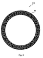
- FIG. 2 is a schematic plan view showing a preferred embodiment when applying the watch external part of the present invention to a cover glass.
- a watch external part P10 is equipped with a substrate P1, a ground layer P2, a coating P3, and an antireflective coating P4.
- the substrate P1 can be constituted using any material, but preferably is an item with transparency.
- the watch external part P10 in addition to the aesthetic appearance when the watch external part P10 are viewed individually, also includes the concerned site in a state with the watch external part P10 incorporated in the watch.
- the transmittance of the light of the substrate P1 is not particularly limited, but is preferably 85 % or greater, and more preferably 90 % or greater.
- Examples of preferred constitutional materials of the substrate P1 include sapphire glass, quartz, plastic and the like.
- the substrate P1 is constituted with materials including one type or two or more types selected from this group, it is possible to have an item with even more excellent aesthetic appearance of the watch external part P10. Also, it is possible to have an even more excellent item in terms of durability of the watch equipped with the watch external part P10.
- the substrate P1 can have a uniform composition at each site, or can have different compositions.
- it can be a laminated body for which layers of different compositions are layered in the thickness direction, or can be constituted with a gradient material for which the composition changes incrementally.
- the coating P3 is formed using the aerosol deposition method.
- the aerosol deposition method means a method by which an aerosol, made by dispersing in gas separately prepared fine particles (fine particles of the material that will become the coating), is sprayed from a nozzle toward the substrate, and by that impact force, the coating is formed on the substrate.
- the aerosol deposition method as described in detail later, there are the features of it being possible to form the coating P3 selectively on desired sites, and it being possible to effectively prevent the occurrence of wasting of materials. It is also possible to omit or simplify front end processing such as mask formation or the like, and back end processing such as removing unnecessary film formation parts or the like. It is also possible to form the coating P3 constituted by materials having an excellent texture.
- the coating P3 being an item formed using the aerosol deposition method, it is possible to provide the watch external part P10 with excellent aesthetic appearance, little waste of materials during manufacturing, and a small burden on the environment.
- the coating P3 can be an item constituted with any material, but constituted using a metal material, the following kinds of effects can be obtained.
- the coating P3 is constituted using a metal material, it is possible to more suitably perform film formation using the aerosol deposition method, and possible to have an item that is particularly excellent in terms of the aesthetic appearance of the watch external part P10. It is also possible to have an item that is particularly excellent in terms of the adhesion between the substrate P1 and the coating P3 (in particular, the adhesion via the ground layer P2), and possible to have an item excellent in terms of the durability of the watch external part P10.
- examples include Au, Pt, Pd, Ni, Ag Al, Cu, Ti, Cr, or alloys including at least one of these or the like, but it is preferable to include Au.
- the coating P3 is constituted with a metal oxide and/or a metal nitride, the following kinds of effects can be obtained.
- the coating P3 is constituted with a metal oxide and/or a metal nitride, it is possible to more suitably perform film formation using the aerosol deposition method, and possible to have an item that is particularly excellent in terms of aesthetic appearance for the watch external part P10. It is also possible to have an item that is particularly excellent in terms of hardness for the coating P3, and possible to have an item that is particularly excellent in terms of durability for the watch external part P10.
- examples include aluminum oxide, titanium oxide, chrome oxide, silicon oxide or the like.
- examples include titanium nitride, chrome nitride, zirconium nitride, hafnium nitride, tantalum nitride, silicon nitride or the like.
- the constitutional material of the coating P3 is not limited to the kinds of items noted above, and for example, it is possible to use various types of materials such as carbon materials, metal carbides, metal borides, pigments and the like.
- coloring agent it is possible to use publicly known items, for example.
- black pigment examples include carbon blacks such as furnace black, channel black, acetylene black, thermal black or the like, copper oxide, manganese dioxide, titanium oxide, aniline black, activated carbon, nonmagnetic ferrite, magnetite or the like.
- yellow pigment examples include chrome yellow, zinc yellow, yellow iron oxide, cadmium yellow, chrome yellow, Hansa yellow, Hansa yellow 10G, benzidine yellow G, benzidine yellow GR, threne yellow, quinoline yellow, permanent yellow NCG and the like.
- examples include red chrome yellow, molybdenum orange, permanent orange GTR, pyrazolone orange, Vulcan orange, benzidine orange G, indanthrene brilliant orange RK, indanthrene brilliant orange GK and the like.
- red pigment examples include iron oxide red, cadmium red, minium, mercury sulfide, watching red, permanent red 4R, lithol red, brilliant carmine 3B, brilliant carmine 6B, Dupont oil red, pyrazolone red, Rhodamine B Lake, lake red C, rose bengal, eosin red, alizarin lake and the like.
- blue pigment examples include Prussian blue, cobalt blue, alkali blue lake, Victoria blue lake, fast sky blue, indathrene blue BC, aniline blue, ultramarine blue, calco oil blue, methylene blue chloride, phthalocyanine blue, phthalocyanine green, malachite green oxalate and the like.
- purple pigment examples include manganese violet, fast violet B, methyl violet lake and the like.
- examples include chrome oxide, chrome green, pigment green, malachite green lake, final yellow green G and the like.
- white pigment examples include zinc oxide, titanium oxide, antimony white, zinc sulfide and the like.
- fillers examples include baryta powder, barium carbonate, clay, silica, white carbon, talc, alumina white and the like.
- dyes examples include various types of dyes such as basic, acidic, disperse, direct dyes and the like, including examples such as nigrosine, methylene blue, rose bengal, quinoline yellow, ultramarine blue and the like.
- the coating P3 is formed by sedimentation of a plurality of particles P31.
- the average primary particle diameter of the particles constituting the coating P3 (primary particle average particle diameter) is preferably 150 ⁇ m or less.
- the average primary particle diameter (average diameter of the primary particles) of the particles constituting the coating P3 is preferably 150 ⁇ m or less, and is more preferably 150 nm or greater and 100 ⁇ m or less.
- the "average particle diameter” indicates the mass standard average particle diameter.
- This average particle diameter can be obtained by measuring the mobility of aerosol, and finding the aerodynamic diameter, for example. Measuring the particle diameter can be done using nanoDMA-SMPS made by TSI Corp., or the like, for example. The average particle diameter can also be found from the measurement results of a scanning electron microscope or transmission electron microscope.
- the coating P3 is preferably selectively provided at a portion of a site that can be observed in a state with the watch external part P10 incorporated in the watch.
- the surface area rate occupied by the site on which the coating P3 is provided is not particularly limited, but it is preferably 70 % or less, and more preferably 2 % or greater and 50 % or less.
- the average thickness of the coating P3 is preferably 0.15 ⁇ m or greater and 100 ⁇ m or less.
- the watch external part P10 is preferably arranged so that the surface on which the coating P3 is provided becomes the inner surface side.
- the coating P3 that the watch external part P10 is equipped with can have a uniform composition at each site, or can have different compositions.
- the watch external part P10 can be an item for which the plurality of types of coating P3 of different textures (e.g., different colors) have a designated pattern. By doing this, it is possible to further increase the aesthetic appearance of the watch external part P10.
- the ground layer P2 is provided between the substrate P1 and the coating P3.
- the average thickness of the ground layer P2 is preferably 0.01 ⁇ m or greater and 10 ⁇ m or less.
- ground layer P2 is able to more effectively exhibit the kinds of functions described previously.
- the ground layer P2 can be constituted using any kind of material, but it is preferably constituted using TiN.
- the ground layer P2 is provided on the entire surface of the side on which the coating P3 is provided of the substrate P1, but for example, it is also possible to have the ground layer P2 selectively provided only on the sites in contact with the coating P3. Also, the ground layer P2 can be provided only on a portion of the site on which the coating P3 is provided.
- the ground layer P2 can have a uniform composition at each site, or can have different compositions.
- it can be constituted with a laminated body for which different compositions are layered in the thickness direction, or with a gradation material for which the composition changes incrementally.
- the antireflective coating P4 is provided on the surface side opposite to the surface of the coating P3 facing the substrate P1.
- the watch external part P10 is used for cover glass (windshield glass)
- cover glass windshield glass
- the effect of improving the aesthetic appearance as noted above is obtained, and it is possible to improve the visibility of the dial, and possible to have an item that is particularly excellent in terms of aesthetic appearance as the overall watch. It is also possible to improve the functions as a practical item, such as by improving the ability to identify the time and the like.
- the thickness of the antireflective coating P4 is not particularly restricted, but it is preferably 0.2 ⁇ m or greater and 10 ⁇ m or less, and more preferably 0.3 ⁇ m or greater and 7 ⁇ m or less.
- the antireflective coating P4 is provided on the entire surface on the side of the substrate P1 on which the coating P3 is provided, but for example it is also possible to have the antireflective coating P4 provided selectively only on a portion of the surface of the side of the substrate P1 on which the coating P3 is provided.
- the watch external part P10 of this embodiment as the cover glass has the coating provided selectively near the outer circumference part when seen with a plan view.
- the coating is provided with a designated pattern (arabesque design).
- a coating P3 with a complex pattern with the present invention, it is possible to obtain an item with little material waste during manufacturing, and a small burden on the environment.
- FIG. 3 is a cross section view schematically showing each step for a preferred embodiment of the manufacturing method of the watch external part of the present invention.
- the manufacturing method of this embodiment has a substrate preparing step (1a) for preparing the substrate P1, a ground layer forming step (1b) for forming the ground layer P2 on the surface of the substrate P1, a coating forming step (1c) for forming the coating P3 using the aerosol deposition method on the surface of the ground layer P2, and an antireflective coating forming step (1d) for forming the antireflective coating P4 on the surface side of the substrate P1 on which the ground layer P2 and the coating P3 are provided.
- the substrate P1 like that described previously is prepared (1a).
- the substrate P1 prepared with this step can also undergo a cleaning process such as a water rinse, alkaline cleaning, acid cleaning, a rinse using an organic solvent or the like.
- ground layer P2 is formed on the surface of the substrate P1 (1b).
- ground layer P2 formed with this step it is preferable that the kinds of conditions described previously be fulfilled.
- the ground layer P2 can be formed, for example, using a vapor phase film deposition method (dry plating method) such as vacuum vapor deposition, ion plating, sputtering, chemical vapor deposition (CVD) or the like, a wet plating method, dipping or the like.
- a vapor phase film deposition method dry plating method
- vacuum vapor deposition ion plating
- sputtering sputtering
- CVD chemical vapor deposition
- wet plating method dipping or the like.
- the coating P3 is formed on a portion of the surface of the ground layer P2 using the aerosol deposition method (1c).
- the coating P3 formed with this step it is preferable that the kinds of conditions described previously are fulfilled.
- the antireflective coating P4 is formed on the surface side of the substrate P1 on which the ground layer P2 and the coating P3 are provided (1d).
- the antireflective coating P4 formed with this step it is preferable that the kinds of conditions described previously are fulfilled.
- the antireflective coating P4 can be formed, for example, using a vapor phase film deposition method (dry plating method) such as vacuum vapor deposition, ion plating, sputtering, chemical vapor deposition (CVD) or the like, a wet plating method, dipping or the like.
- a vapor phase film deposition method dry plating method
- vacuum vapor deposition ion plating
- sputtering chemical vapor deposition (CVD) or the like
- CVD chemical vapor deposition
- FIG. 4 is a vertical cross section side view showing a preferred embodiment of the coating forming device used to form the coating.
- FIG. 5 is a vertical cross section side view showing an example of the constitution of the crushing device that the coating forming device is equipped with.
- FIG. 6 is a block diagram of the key parts of the coating forming device shown in FIG. 4 .
- an x axis, y axis, and z axis are shown as the three axes orthogonal to each other.
- the x axis is the axis along one direction among the horizontal directions
- the y axis is the axis along the direction perpendicular to the x axis which is the horizontal direction
- the z axis is the axis along the vertical direction (up-down direction).
- the tip side of each arrow in the drawing is the "positive side (+ side)” and the base side is the “negative side (- side).”
- the upper side in FIG. 4 is called “top (above),” and the lower side is called “bottom (below).”
- an illustration of the ground layer P2 provided on the substrate P1 is omitted.
- the coating forming device 1 is an "aerosol deposition device" for forming the coating P3.
- the aerosol deposition device is a device by which an aerosol, made by separately prepared fine particles (fine particles of the coating material) being dispersed in gas, is sprayed from a nozzle toward the substrate, and by that impact force, the coating is formed on the substrate.
- the coating forming device 1 is equipped with an aerosol generator 15, a crushing device 4, a film forming chamber 16, a coupling tube 2, a coupling tube 8, a gas supply means or gas supplier 3, a pressure adjustment means or pressure adjuster 5, a moving means or unit 6, and a control unit or controller7.
- the aerosol generator 15 is constituted to be able to maintain airtightness, and the particles P31 that will become the coating P3 can be housed in its interior.
- the crushing device 4 is linked to the aerosol generator 15 by the coupling tube 8.
- the crushing device 4 has the function of crushing the particles P31 included in the aerosol generated by the aerosol generator 15.
- the film forming chamber 16 is provided independently from the aerosol generator 15 and the crushing device 4. This film forming chamber 16 is also constituted so as to be able to maintain airtightness, and can house a plurality of substrates P1 in its interior.
- the chamber temperature inside the film forming chamber 16 is adjusted to 25 °C or greater and 30 °C or less for example by cooling, specifically, using a cooling medium that passes through the piping.
- the coupling tube 2 links the crushing device 4 and the film forming chamber 16, and its cavity part 22 functions as a flow path through which particles P31 that become the coating P3 flow.
- the aerosol generator 15 and the film forming chamber 16 are in communication via the coupling tube 8, the crushing device 4, and the coupling tube 2.
- the second opening part 21 is arranged in parallel in relation to the surface direction of the substrate P1 housed in the film forming chamber 16. Then, the particles P31 that pass through the coupling tube 2 (cavity part 22), and those particles are sprayed from the second opening part 21 onto the substrate P1. By doing this, the coating P3 is formed on the substrate P1 (specifically, with this embodiment, the surface of the ground layer P2). In this way, with the coupling tube 2, the second opening part 21 side part functions as a nozzle part 24.
- the average inner diameter of the coupling tube 2 is not particularly limited, but for example is preferably 1 mm or greater and 10 mm or less. Also, the inner diameter of the second opening part 21 is not particularly limited, but for example is preferably 0.1 mm or greater and 1 mm or less.
- the constitutional material of the coupling tube 2 though not particularly limited, it is possible to use a metal material such as stainless steel or the like, for example.
- heating mechanism 90 that heats the coupling tube 2 on the outer circumference part of the coupling tube 2. With this heating mechanism 90, it is possible to prevent adhesion of particles P31 that pass through the coupling tube 2 onto the coupling tube 2-inner circumference part (inner wall).
- the heating temperature though not particularly limited, it is preferable to be for example 100 °C or greater and 300 °C or less, and more preferably 250 °C and 300 °C or less.
- the gas supply means 3 supplies gas to the inside of the aerosol generator 15.
- this supply volume though not particularly limited, for example it is preferable to be 1 L/minute or greater and 90 L/minute or less.
- the gas supply means 3 has a tank 31 in which the gas is filled, a coupling tube 32 that links the tank 31 and the aerosol generator 15, and a solenoid valve 33 arranged midway in the coupling tube 32.
- the tank 31 can pool the gas in an airtight manner.
- the gas pooled in the tank 31 though not particularly limited, for example, it is possible to use nitrogen gas, or otherwise also possible to use an inert gas such as helium, argon or the like. Also, when using an item with particles P31 constituted using a metal oxide, it is possible to suitably use an item including oxygen as the gas. By doing this, it is possible to prevent unintentional reduction of the particles P31.
- the tank 31 and the aerosol generator 15 are in communication via the coupling tube 32.
- This coupling tube 32 can be a rigid item or can be a flexible item.
- a solenoid valve 33 is arranged midway in the lengthwise direction on the coupling tube 32.
- the solenoid valve 33 opens and closes the coupling tube 32. Then, when the solenoid valve 33 is in an open state, the tank 31 and the aerosol generator 15 are in communication. By doing this, supplying of the gas from the tank 31 to the aerosol generator 15 is performed. Also, when the solenoid valve 33 is in the closed state, communication between the tank 31 and the aerosol generator 15 is blocked. By doing this, the supply of the gas from the tank 31 to the aerosol generator 15 is stopped.
- the particles P31 housed in the aerosol generator 15 are dispersed in gas and aerosol is generated.
- the aerosol generated inside the aerosol generator 15 in this way is introduced inside the crushing device 4 via the coupling tube 8 by the gas from the tank 31 functioning as a carrier gas.
- the crushing device 4 is equipped with a container 41 in which aerosol containing particles P31 is introduced, an aerosol introduction port 42 in which aerosol including particles P31 is introduced from the coupling tube 8, a crushing tool 43 for performing crushing of the particles P31, an aerosol lead-out port 44 for leading out the aerosol including the crushed particles P31 to the coupling tube 2, a brush 45 for removing particles P31 when they have adhered to the crushing tool 43, gas introduction ports 46a and 46b for introducing gas to the inside of the container 31, and an ultrasonic vibration device 47.
- the aerosol introduction port 42 is arranged inside the container 41, and at its tip is arranged the cylindrical crushing tool 43 in state by which it can be axially rotated by a motor (not illustrated).
- the opening of the aerosol introduction port 42 is a slit for which the cylinder axis direction of the crushing tool 43 is the long side.
- the width of that slit is not particularly limited, but is preferably 1 mm or less.
- the crushing tool 43 it is preferable to use an item for which the cylinder side surface impacted by the aerosol is constituted with a material with a high level of hardness such as titanium carbide or the like.
- the aerosol lead-out port 44 is arranged above the crushing tool 43. Also, the brush 45 is arranged so as to contact the crushing tool 43.
- the gas introduction ports 46a and 46b are arranged in the space from the crushing tool 43 to the aerosol lead-out port 44, and the ultrasonic vibration device 47 is arranged at the outer circumference part of the aerosol lead-out port 44.
- the aerosol generated with the aerosol generator 15 is accelerated by the aerosol introduction port 42, and is made to collide with the cylinder side surface of the crushing tool 43.
- the bold arrow in the drawing shows the advancing direction of the aerosol.
- the crushing tool 43 rotates in the clockwise direction as shown by the arrow in the drawing. Therefore, the aerosol for which the introduced position gradually changes impacts the cylinder side surface of the aerosol crushing tool 43 while always changing the impact surface. By doing this, even when the aerosol generated with the aerosol generator 15 contains a relatively large amount of agglomerated particles, it is possible to efficiently crush those agglomerated particles.
- the aerosol introduced from the aerosol introduction port 42 collides diagonally with the cylinder side surface of the crushing tool 43, so though the majority of the aerosol is reflected along the tangent line of the cylinder side surface, since there is a certain degree of spreading width, it is possible to have it impact and adhere to the inner wall of the aerosol lead-out port 44, but to prevent this, it is suitable to devise this so that gas is introduced from the gas introduction ports 46a and 46b, a curtain-like gas film is formed on the inner surface of the aerosol lead-out port 44 to prevent adhering, the ultrasonic vibration device 47 is operated to vibrate the aerosol lead-out port 44, and adhesion does not progress.
- the small arrows from the gas introduction ports 46a and 46b show the flow of gas introduced from here. Furthermore, by ionizing the introduced gas in advance, it is preferable to neutralize the surface charge and prevent re-agglomeration in the aerosol.
- the aerosol converted to an aerosol rich with primary particles and lead out in this way is lead to a nozzle (not illustrated), and therefore it is possible to form a structure without trouble and with few defects over the long term.
- the aerosol converted to the item rich in primary particles with the crushing device 4 is introduced to the coupling tube 2, and is sprayed from the second opening part 21 onto the substrate P1. Then, the particles P31 are impacted and adhered to the substrate P1, and as a result, the coating P3 is formed.
- the pressure adjustment means 5 is an item that makes the pressure inside the film forming chamber 16 lower than the pressure inside the aerosol generator 15 and the pressure inside the crushing device 4.
- the pressure adjustment means 5 has a pump 51 that suctions the inside of the film forming chamber 16, a coupling tube 52 that links the pump 51 and the film forming chamber 16, and a solenoid valve 53 that is arranged midway in the coupling tube 52.
- the pump 51 is an item that suctions the gas G 2 inside the film forming chamber 16. By this suction, the gas G 2 inside the film forming chamber 16 is exhausted via the coupling tube 52, and thus, the pressure inside the film forming chamber 16 is reliably lower than the pressure inside the aerosol generator 15 and the pressure inside the crushing device 4. By doing this, it is possible to reliably flow the particles P31 inside the film forming chamber 16, and thus possible to reliably form the coating P3.
- the pump 51 though this is not particularly limited, for example, it is possible to use a turbo-molecular pump, a dry pump, a mechanical booster pump, a rotary pump or the like.
- the pump 51 is linked to the film forming chamber 16 via the coupling tube 52.
- This coupling tube 52 can be a rigid item or a flexible item.
- the solenoid valve 53 is arranged midway in the lengthwise direction on the coupling tube 52.
- the solenoid valve 53 opens and closes the coupling tube 52. Also, when the solenoid valve 53 is in an open state, by the suction force of the pump 51, it is possible to suction the inside of the film forming chamber 16, and thus, possible to reduce the pressure inside the film forming chamber 16. Also, when the solenoid valve 53 is in a closed state, the suction force of the pump 51 is blocked from acting inside the film forming chamber 16.
- the moving means 6 moves the substrate P1 in relation to the second opening part 21 facing the y axis direction.
- the moving means 6 has a stage (table) 61 for conveying a plurality of substrates P1, a y axis motor 62y for moving the stage 61 facing the y axis direction, and a y axis motor driver 63y for controlling the driving of the y axis motor 62y.
- the moving means 6 has an x axis motor 62x that can move the stage 61 in the x axis direction and perform that movement, and an x axis motor driver 63x that controls the driving of the x axis motor 62x.
- the stage 61 is a member that forms a plate form constituted by a metal material such as stainless steel or the like, for example. This stage 61 is supported horizontally.
- the y axis motor 62y is for example a servo motor, and is linked to the stage 61 via a ball screw (not illustrated) or the like. Then, by the y axis motor 62y rotating, the rotation force is transmitted to the stage 61 via the ball screw. By doing this, it is possible to move the plurality of substrates P 1 placed on the stage 61 in the y axis direction for each stage 61.
- the y axis motor 62y is electrically connected to the y axis motor driver 63y.
- this y axis motor driver 63y By the control of this y axis motor driver 63y, it is possible to change the rotation count of the y axis motor 62y. By doing this, the speed when moving the stage 61, specifically, the speed during operation of the moving means 6 becomes variable. Then, it is possible to respectively adjust the thickness of the coating P3 that is formed according to the size of that speed. For example, when the speed is "high,” a "thin” coating P3 is formed, and when the speed is “low,” a "thick” coating P3 is formed.
- the x axis motor 62x is for example a servo motor, and is linked to the stage 61 via a ball screw (not illustrated) or the like. Then, by the x axis motor 62x rotating, the rotation force is transmitted to the stage 61 via the ball screw. By doing this, it is possible to move the plurality of substrates P1 placed on the stage 61 in the x axis direction for each stage 61.
- the x axis motor 62x is electrically connected to the x axis motor driver 63x.
- the control unit 7 respectively controls each operation of the gas supply means 3, the pressure adjustment means 5, the moving means 6 and the like.
- the control unit 7 is a personal computer (PC) with a built in CPU (Central Processing Unit), for example.
- control unit 7 is electrically connected respectively to the solenoid valve 33 of the gas supply means 3, the pump 51 and the solenoid valve 53 of the pressure adjustment means 5, and the x axis motor driver 63x and the y axis motor driver 63y of the moving means 6. Then, the control unit 7 can respectively operate these individually.
- a control program is stored in advance a storage unit (recording media) 71 built into the control unit 7.
- the storage unit 71 is constituted by, for example, magnetic or optical recording media such as a RAM (Random Access Memory: including volatile and nonvolatile), FD (Floppy Disk (Floppy is a registered trademark)), HD (Hard Disk), CD-ROM (Compact Disk Read-Only Memory) or the like, or semiconductor memory.
- RAM Random Access Memory: including volatile and nonvolatile
- FD Flexible Disk (Floppy is a registered trademark)
- HD Hard Disk
- CD-ROM Compact Disk Read-Only Memory
- alignment of the stage 61 to the second opening part 21 of the coupling tube 2 is performed so as to have the second opening part 21 of the coupling tube 2 face the substrate P1.
- This alignment is performed using a CCD (Charge Coupled Device) camera, based on an image taken using that CCD camera.
- CCD Charge Coupled Device
- the pressure adjustment means 5 operates. By doing this, the pressure inside the film forming chamber 16 is lower than the pressure inside the aerosol generator 15. This state is maintained until the formation of the coating P3 on the substrate P1 is completed.
- the gas supply means 3 also operates.
- the moving means 6 is made to operate, specifically, the stage 61 is moved in the y axis positive direction.
- the aerosol containing particles P31 generated inside the aerosol generator 15 reliably passes through the coupling tube 2 toward the film forming chamber 16.
- the particles P31 can be smoothly passed through the coupling tube 2 by a carrier gas. After that, the particles P31 are exhausted from the second opening part 21, and sprayed in sequence on each substrate P1 and adhered. By doing this, it is possible to rapidly form the coating P3 having the desired shape on the desired sites of the substrate P1.
- the manufacturing method of the watch external part of the present invention like that described previously, it is possible to efficiently manufacture the watch external part with excellent aesthetic appearance with a method that has little waste of materials, and a small burden on the environment.
- the watch of the present invention has the watch external part of the present invention like that described above.
- the watch of the present invention is acceptable as long as it is equipped with the watch external part of the present invention as at least one of the watch external part, and as other parts, it is possible to use publicly known items, but hereafter, we'll describe an example of the constitution of the watch of the present invention.
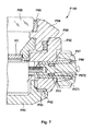
- FIG. 7 is a partial cross section diagram showing a preferred embodiment of the watch (wristwatch) of the present invention.
- the wristwatch (portable timepiece) P 100 of this embodiment is equipped with a barrel (case) P82, a back cover P83, a bezel (edge) P84, and a glass plate (cover glass) P85. Also, inside the case P82 are housed a timepiece dial P7, a solar battery P94, and a movement P81, and furthermore, hands (indicator needles) (not illustrated) and the like are housed.
- the glass plate P85 is normally constituted with a high transparency level transparent glass, sapphire or the like. By doing this, it is possible to have sufficiently excellent visibility of the timepiece dial P7, the hands, and the like, and also possible to have light of a sufficient light volume made incident on the solar battery P94.
- the movement P81 uses the electromotive force of the solar battery P94 to drive the indicator needles.
- the movement P81 inside the movement P81 are equipped, for example, an electric double layer capacitor or a lithium ion secondary battery for storing the electromotive force of the solar battery P94, a quartz resonator as a time reference source, a semiconductor integrated circuit for generating a drive pulse to drive the watch based on the oscillating frequency of the quartz resonator, a step motor for driving the indicator needles every second after receiving the drive pulse, a gear train mechanism for transmitting the movement of the step motor to the indicator needles and the like.
- an electric double layer capacitor or a lithium ion secondary battery for storing the electromotive force of the solar battery P94
- a quartz resonator as a time reference source
- a semiconductor integrated circuit for generating a drive pulse to drive the watch based on the oscillating frequency of the quartz resonator
- a step motor for driving the indicator needles every second after receiving the drive pulse
- a gear train mechanism for transmitting the movement of the step motor to the indicator needles and the like.
- the movement P81 is equipped with an antenna for radio wave reception (not illustrated). Also, there is a function for performing time adjustment and the like using the received radio waves.
- the solar battery P94 has a function of converting light energy to electrical energy. Also, the electrical energy converted using the solar battery P94 is used for driving the movement and the like.
- the solar battery P94 for example, has a pin structure for which p type impurities and n type impurities are selectively introduced to a non-monocrystal silicon thin film, and furthermore, is equipped with an i type non-monocrystal silicon thin film having a low impurity concentration between a p type non-monocrystal silicon thin film and an n type non-monocrystal silicon thin film.
- a winding stem pipe P86 is fit into and fixed to the barrel P82, and a shaft part P871 of a winding knob P87 is inserted so as to be able to rotate inside this winding stem pipe P86.
- the barrel P82 and the bezel P84 are fixed by a plastic packing P88, and the bezel P84 and the glass plate P85 are fixed by a plastic packing P89.
- the back cover P83 is fit (or screwed) onto the barrel P82, and a ring shaped rubber packing (back cover packing) P92 is interposed in a compressed state in the junction part (seal part) P93 of these.
- the seal part P93 is sealed fluid tight, and a waterproofing function is obtained.
- a groove P872 is formed on the outer circumference midway on the shaft part P871 of the winding knob P87, and a ring shaped rubber packing (winding knob packing) P91 is fit inside this groove P872.
- the rubber packing P91 is tightly adhered to the inner circumference surface of the winding stem pipe P86, and is compressed between that inner circumference surface and the inner surface of the groove P872. With this constitution, between the winding knob P87 and the winding stem pipe P86 is sealed liquid tight, and a waterproofing function is obtained.
- the rubber packing P91 rotates together with the shaft part P871, and slides in the circumferential direction while tightly adhering to the inner circumference surface of the winding stem pipe P86.
- a wristwatch portable timepiece
- a table clock a wall clock
- the present invention can be applied to any timepiece such as a solar clock other than a solar radio clock, a radio clock other than a solar radio clock or the like.
- each part can be substituted with any constitutional item that exhibits the same function, and any constitution can also be added.
- the focus of our description was on the case of the watch external part being equipped with, in addition to the substrate and the coating, the ground layer and the antireflective coating, but as long as the watch external part of the present invention is equipped with the substrate and the coating, it can be an item for which at least one of the ground layer and the antireflective coating is not equipped.
- the opening part of the coupling tube of the coating forming device faces the z axis negative direction with the first embodiment, but the invention is not limited to this, and for example, can also face the x axis positive direction, the x axis negative direction, the y axis positive direction, the y axis negative direction, or the z axis positive direction.
- the moving means of the coating forming device is constituted so as to move the substrate in the y axis positive direction in relation to the nozzle part of the coupling tube, but the invention is not limited to this, and for example, can also be constituted so as to move the nozzle part of the coupling tube in the y axis positive direction in relation to the substrate.
- the moving means of the coating forming device can also be constituted to be able to move the stage in the z axis direction. It is also possible to constitute the stage to be able to be rotated.
- the coating forming device when forming the coating on the substrate, with this embodiment, the formation was performed while moving the stage, but the invention is not limited to this, and for example, it is also possible to stop the movement of the stage and perform formation each time the nozzle is positioned on the substrate.
- the coating forming device as being equipped with a crushing device, but to form the coating, it is also possible to not be equipped with the crushing device.
- the coating forming device as being equipped with a heating mechanism that heats the coupling tube, but to form the coating, it is also possible to not be equipped with the heating mechanism.
Landscapes
- Physics & Mathematics (AREA)
- General Physics & Mathematics (AREA)
- Engineering & Computer Science (AREA)
- Manufacturing & Machinery (AREA)
- Other Surface Treatments For Metallic Materials (AREA)
- Application Of Or Painting With Fluid Materials (AREA)
Abstract
Description
- This application claims priority to Japanese Patent Application No.
2014-016244 filed on January 30, 2014 2014-016244 - The present invention relates to a watch external part, a manufacturing method for a watch external part, and a watch.
- For watches, in addition to a demand for functions as a practical article, there is also a demand for excellent esthetics (aesthetic appearance) as a decorative item.
- Because of this, for the watch external part, materials having an excellent texture such as various types of metal material or the like are used (see
JP-A-2008-150660 - Then, to further improve the esthetics, providing of a decorative layer (coating) with a designated pattern is performed.
- In the past, to provide a decorative layer (coating) with a designated pattern, a method was used such as performing vapor phase film deposition such as vacuum vapor deposition or the like in a state with a mask (resist or the like) arranged, and removing the unnecessary parts using etching after film formation was performed on the entire surface of the substrate.
- However, with these methods, the constitutional materials of the coating included in the final watch external part are only a tiny portion of the materials used for manufacturing, so there was a great deal of wasted material, and this was not desirable from the perspective of saving resources.
- Also, recovery of the coating forming materials, recycling of the recovered material, and an increase in the steps accompanying use of resist or the like and use of chemical substances caused problems including being a burden on the environment and increasing costs.
- One aspect of the present invention is to provide a watch external part with excellent aesthetic appearance, little waste of materials during manufacturing, and a small burden on the environment, to provide a manufacturing method for a watch external part that, with a method with little wasted materials and a small burden on the environment, is able to efficiently manufacture the watch external part with excellent aesthetic appearance, and to provide a watch equipped with a watch external part with excellent aesthetic appearance, little waste of materials during manufacturing, and a small burden on the environment.
- This kind of aspect is achieved using the present invention noted below.
- The watch external part of the present invention is equipped with a substrate, and a coating formed using an aerosol deposition method.
- By doing this, it is possible to provide a watch external part with excellent aesthetic appearance, little waste of materials during manufacturing, and a small burden on the environment.
- With the watch external part of the present invention, it is preferable that the coating be selectively provided at a portion of a site observable in a state with the watch external part incorporated in a watch.
- By doing this, it is possible to have particularly excellent aesthetic appearance for the watch external part and the watch.
- With the watch external part of the present invention, it is preferable that the substrate be transparent.
- By doing this, for example, it is possible to have particularly excellent aesthetic appearance for the watch external part. Also, for example, with a watch equipped with a watch external part, even in a case when the surface on the side facing opposite the surface on which the coating of the watch external part is provided is arranged so as to face the outside surface side, the user or the like can visually recognize the coating well, and it is possible to more reliably prohibit damage due to friction or the like of the coating or the like while effectively exhibiting the effect of being equipped with the coating, and possible to have that watch have particularly excellent durability.
- With the watch external part of the present invention, it is preferable that the substrate be made of a material including one type or two or more types selected from a group consisting of sapphire glass, quartz, and plastic.
- Because of that, it is possible to have the aesthetic appearance of the watch external part be even more excellent. Also, it is possible to have the durability of the watch equipped with the watch external part be even more excellent.
- The watch external part of the present invention is further equipped with a ground layer having at least one layer between the substrate and the coating.
- By doing this, for example, it is possible for the adhesion between the substrate and the coating to be particularly excellent. Also, for example, by having the ground layer function as a colored layer, it is also possible to further improve the aesthetic appearance of the watch external part. Also, by having the ground layer function as a gap layer, it is possible to obtain an external appearance with a three-dimensional feeling such as that the coating is raised up.
- With the watch external part of the present invention, it is preferable that the ground layer be a layer made of TiN.
- By doing this, it is possible to have an item with particularly excellent adhesion between the substrate and the coating, and particularly the adhesion when the coating is constituted by a metal material or a metal oxide or metal nitride.
- With the watch external part of the present invention, it is preferable that the coating be made of a metal material.
- By doing this, it is possible to more suitably perform film formation using the aerosol deposition method, and possible to have an item with particularly excellent aesthetic appearance of the watch external part. Also, it is also possible to have an item with particularly excellent adhesion between the substrate and the coating, and possible to have an item with particularly excellent durability of the watch external part.
- With the watch external part of the present invention, it is preferable that the coating be made of a metal oxide and/or a metal nitride.
- By doing this, it is possible to more suitably perform film formation using the aerosol deposition method, and possible to have an item with particularly excellent aesthetic appearance of the watch external part. Also, it is possible to have an item with particularly excellent coating hardness, and possible to have an item with particularly excellent durability of the watch external part.
- The watch external part of the present invention is further equipped with an antireflective coating disposed on a surface side opposite to a surface of the coating facing the substrate.
- By doing this, it is possible to effectively prevent unintentional glare of external light, and possible to have an item with particularly excellent aesthetic appearance of the watch external part. Also, in a case when the watch external part are used for a cover glass (windshield glass), it is possible to obtain the effect of improving the aesthetic appearance as noted above, to improve the visibility of the dial, and also possible to have an item with particularly excellent aesthetic appearance as an overall watch. Also, functions as a practical item are improved, such as the ability to identify the time and the like.
- A manufacturing method for a watch external part of the present invention includes preparing a substrate, and forming a coating using an aerosol deposition method.
- By doing this, it is possible to provide a manufacturing method for a watch external part that, with a method with little wasted materials and a small burden on the environment, is able to efficiently manufacture the watch external part with excellent aesthetic appearance.
- The manufacturing method for a watch external part of the present invention preferably includes forming a ground layer having at least one layer between the preparing of the substrate and the forming of the coating.
- By doing this, for example, it is possible to have an item with particularly excellent adhesion between the substrate and the coating. Also, for example, by having the ground layer function as a colored layer, it is also possible to further improve the aesthetic appearance of the watch external part. Also, by having the ground layer function as a gap layer, it is possible to obtain an external appearance with a three-dimensional feeling such as with the coating raised up.
- The manufacturing method for a watch external part of the present invention preferably includes forming an antireflective coating after the forming of the coating.
- By doing this, it is possible to effectively prevent unintentional glare of outside light, and possible to have an item with particularly excellent aesthetic appearance of the watch external part. Also, in a case when the watch external part are used for a cover glass (windshield glass), it is possible to obtain the effect of improving the aesthetic appearance as noted above, and to improve the visibility of the dial, and also possible to have an item with particularly excellent aesthetic appearance as an overall watch. Also, functions as a practical item are improved, such as the ability to identify the time and the like.
- A watch of the present invention is equipped with the watch external part of the present invention.
- By doing this, it is possible to provide a watch equipped with a watch external part with excellent aesthetic appearance, little waste of materials during manufacturing, and a small burden on the environment.
- A watch of the present invention is equipped with the watch external part manufactured using the manufacturing method of the present invention.
- By doing this, it is possible to provide a watch equipped with a watch external part with excellent aesthetic appearance, little waste of materials during manufacturing, and a small burden on the environment.
- Referring now to the attached drawings which form a part of this original disclosure:
-
FIG. 1 is a schematic cross section diagram showing a preferred embodiment of the watch external part of the present invention; -
FIG. 2 is a schematic plan view showing a preferred embodiment when the watch external part of the present invention are used for a cover glass; -
FIG. 3 is a cross section view schematically showing each step for a preferred embodiment of the manufacturing method of the watch external part of the present invention; -
FIG. 4 is a vertical cross section side view showing a preferred embodiment of the coating forming device used to form the coating; -
FIG. 5 is a vertical cross section side view showing an example of the constitution of the crushing device the coating forming device is equipped with; -
FIG. 6 is a block diagram of the key parts of the coating forming device shown inFIG. 4 ; and -
FIG. 7 is a partial cross section diagram showing a preferred embodiment of the watch (portable timepiece) of the present invention. - Following, we will give a detailed description of the watch external part, the manufacturing method of a watch external part, and the watch of the present invention based on preferred embodiments shown in the attached drawings.
- First, we will describe the watch external part of the present invention.
- With the present invention, the watch external part are constitutional parts of the watch, and mean parts that are visible from the outside when using the watch, and in addition to items that are used when the watch exterior is exposed, include the concept of parts housed on the interior of the watch.
- As a watch external part, examples include a cover glass (windshield glass), a dial, hands (hour hand, minute hand, second hand, and the like), a bezel, a case, a back cover, a winding knob, rotating displays such as a round disk hand, day indicator, month indicator, moon phase disk and the like.
-
FIG. 1 is a schematic cross section view showing a preferred embodiment of the watch external part of the present invention, andFIG. 2 is a schematic plan view showing a preferred embodiment when applying the watch external part of the present invention to a cover glass. - As shown in
FIG. 1 , a watch external part P10 is equipped with a substrate P1, a ground layer P2, a coating P3, and an antireflective coating P4. - The substrate P1 can be constituted using any material, but preferably is an item with transparency.
- By doing this, for example, it is possible to have an item with particularly excellent aesthetic appearance of the watch external part P10. Also, for example, with a watch equipped with the watch external part P10, even in a case when the arranged so that the surface of the side opposite to the surface on which the coating P3 is provided faces the outer surface side, it is possible for the user to suitably visually recognize the coating P3, and while effectively exhibiting the effect of being equipped with the coating P3, to more reliably prevent damage due to friction or the like with the coating P3 or the like, and possible to have an item with particularly excellent durability for that watch. With this specification, the "aesthetic appearance of the watch external part P10", in addition to the aesthetic appearance when the watch external part P10 are viewed individually, also includes the concerned site in a state with the watch external part P10 incorporated in the watch.
- The transmittance of the light of the substrate P1 (transmittance of light of wavelength 600 nm) is not particularly limited, but is preferably 85 % or greater, and more preferably 90 % or greater.
- Examples of preferred constitutional materials of the substrate P1 include sapphire glass, quartz, plastic and the like.
- When the substrate P1 is constituted with materials including one type or two or more types selected from this group, it is possible to have an item with even more excellent aesthetic appearance of the watch external part P10. Also, it is possible to have an even more excellent item in terms of durability of the watch equipped with the watch external part P10.
- The substrate P1 can have a uniform composition at each site, or can have different compositions. For example, it can be a laminated body for which layers of different compositions are layered in the thickness direction, or can be constituted with a gradient material for which the composition changes incrementally.
- The coating P3 is formed using the aerosol deposition method.
- With the present invention, the aerosol deposition method means a method by which an aerosol, made by dispersing in gas separately prepared fine particles (fine particles of the material that will become the coating), is sprayed from a nozzle toward the substrate, and by that impact force, the coating is formed on the substrate. With the aerosol deposition method, as described in detail later, there are the features of it being possible to form the coating P3 selectively on desired sites, and it being possible to effectively prevent the occurrence of wasting of materials. It is also possible to omit or simplify front end processing such as mask formation or the like, and back end processing such as removing unnecessary film formation parts or the like. It is also possible to form the coating P3 constituted by materials having an excellent texture.
- In this way, by the coating P3 being an item formed using the aerosol deposition method, it is possible to provide the watch external part P10 with excellent aesthetic appearance, little waste of materials during manufacturing, and a small burden on the environment.
- Also, with the aerosol deposition method, it is not necessary to use volatile solvents or the like, so in a state with the watch external part P10 incorporated in a watch, it is possible to effectively prevent the occurrence of problems (movement failure, the occurrence of trouble, clouding or the like of the cover glass or the like) due to volatilization of the volatile components (volatile organic compounds).
- The coating P3 can be an item constituted with any material, but constituted using a metal material, the following kinds of effects can be obtained.
- Specifically, when the coating P3 is constituted using a metal material, it is possible to more suitably perform film formation using the aerosol deposition method, and possible to have an item that is particularly excellent in terms of the aesthetic appearance of the watch external part P10. It is also possible to have an item that is particularly excellent in terms of the adhesion between the substrate P1 and the coating P3 (in particular, the adhesion via the ground layer P2), and possible to have an item excellent in terms of the durability of the watch external part P10.
- As the metal material constituting the coating P3, examples include Au, Pt, Pd, Ni, Ag Al, Cu, Ti, Cr, or alloys including at least one of these or the like, but it is preferable to include Au.
- By doing this, it is possible to have an item that is even more excellent in terms of aesthetic appearance for the watch external part P10. Also, Au is an expensive precious metal, and is especially high in terms of burden on the environment by substances used to recover items that were not used in film formation. Therefore, when the coating P3 is a metal material containing Au, there is more marked exhibiting of the effects due to using the present invention.
- Also, when the coating P3 is constituted with a metal oxide and/or a metal nitride, the following kinds of effects can be obtained.
- Specifically, when the coating P3 is constituted with a metal oxide and/or a metal nitride, it is possible to more suitably perform film formation using the aerosol deposition method, and possible to have an item that is particularly excellent in terms of aesthetic appearance for the watch external part P10. It is also possible to have an item that is particularly excellent in terms of hardness for the coating P3, and possible to have an item that is particularly excellent in terms of durability for the watch external part P10.
- As the metal oxide constituting the coating P3, examples include aluminum oxide, titanium oxide, chrome oxide, silicon oxide or the like.
- As the metal nitride constituting the coating P3, examples include titanium nitride, chrome nitride, zirconium nitride, hafnium nitride, tantalum nitride, silicon nitride or the like.
- The constitutional material of the coating P3 is not limited to the kinds of items noted above, and for example, it is possible to use various types of materials such as carbon materials, metal carbides, metal borides, pigments and the like.
- As a coloring agent, it is possible to use publicly known items, for example.
- In specific terms, as a black pigment, examples include carbon blacks such as furnace black, channel black, acetylene black, thermal black or the like, copper oxide, manganese dioxide, titanium oxide, aniline black, activated carbon, nonmagnetic ferrite, magnetite or the like. Also, as a yellow pigment, examples include chrome yellow, zinc yellow, yellow iron oxide, cadmium yellow, chrome yellow, Hansa yellow, Hansa yellow 10G, benzidine yellow G, benzidine yellow GR, threne yellow, quinoline yellow, permanent yellow NCG and the like.
- Also, as orange pigments, examples include red chrome yellow, molybdenum orange, permanent orange GTR, pyrazolone orange, Vulcan orange, benzidine orange G, indanthrene brilliant orange RK, indanthrene brilliant orange GK and the like. As red pigment, examples include iron oxide red, cadmium red, minium, mercury sulfide, watching red, permanent red 4R, lithol red, brilliant carmine 3B, brilliant carmine 6B, Dupont oil red, pyrazolone red, Rhodamine B Lake, lake red C, rose bengal, eosin red, alizarin lake and the like.
- As blue pigment, examples include Prussian blue, cobalt blue, alkali blue lake, Victoria blue lake, fast sky blue, indathrene blue BC, aniline blue, ultramarine blue, calco oil blue, methylene blue chloride, phthalocyanine blue, phthalocyanine green, malachite green oxalate and the like. As purple pigment, examples include manganese violet, fast violet B, methyl violet lake and the like.
- As green pigment, examples include chrome oxide, chrome green, pigment green, malachite green lake, final yellow green G and the like. As white pigment, examples include zinc oxide, titanium oxide, antimony white, zinc sulfide and the like. As fillers, examples include baryta powder, barium carbonate, clay, silica, white carbon, talc, alumina white and the like. Furthermore, as dyes, examples include various types of dyes such as basic, acidic, disperse, direct dyes and the like, including examples such as nigrosine, methylene blue, rose bengal, quinoline yellow, ultramarine blue and the like.
- The coating P3 is formed by sedimentation of a plurality of particles P31.
- The average primary particle diameter of the particles constituting the coating P3 (primary particle average particle diameter) is preferably 150 µm or less.
- By doing this, it is possible to have an item particularly excellent in terms of aesthetic appearance for the watch external part P10. It is also possible to have an item that is particularly excellent in terms of adhesion between the substrate P1 and the coating P3 (particularly the adhesion via the ground layer P2), and possible to have an item that is particularly excellent in terms of durability of the watch external part P10.
- The average primary particle diameter (average diameter of the primary particles) of the particles constituting the coating P3 is preferably 150 µm or less, and is more preferably 150 nm or greater and 100 µm or less.
- With this specification, the "average particle diameter" indicates the mass standard average particle diameter. This average particle diameter can be obtained by measuring the mobility of aerosol, and finding the aerodynamic diameter, for example. Measuring the particle diameter can be done using nanoDMA-SMPS made by TSI Corp., or the like, for example. The average particle diameter can also be found from the measurement results of a scanning electron microscope or transmission electron microscope.
- The coating P3 is preferably selectively provided at a portion of a site that can be observed in a state with the watch external part P10 incorporated in the watch.
- By doing this, it is possible to have particularly excellent aesthetic appearance for the watch external part P10 and the watch by the effect of the coating P3 itself having a special pattern, or the effect by combining sites where the coating P3 is provided and sites where the coating P3 is not provided.
- Also, in the past, in a state with the watch external part incorporated in the watch, when the coating is selectively provided on a portion of the site that can be observed, there were problems such as that waste of material during manufacturing of the watch external part was especially high, but with the present invention, it is possible to reliably prevent the occurrence of this kind of problem. Therefore, when the coating P3 is selectively provided in a portion of the site that can be observed in a state with the watch external part P10 incorporated in the watch, there is more marked exhibition of the effects of the present invention.
- In a state with the watch external part P10 incorporated in the watch, of the sites that can be observed of the watch external part P10, the surface area rate occupied by the site on which the coating P3 is provided (when the surface of the watch external part P10 is flat, the surface area rate when observed from the normal line direction of that surface) is not particularly limited, but it is preferably 70 % or less, and more preferably 2 % or greater and 50 % or less.
- By doing this, the effects like those described previously are more markedly exhibited.
- The average thickness of the coating P3 is preferably 0.15 µm or greater and 100 µm or less.
- By doing this, it is possible to have an item that is particularly excellent in terms of aesthetic appearance for the watch external part P10. It is also possible to have an item that is particularly excellent in terms of durability of the watch external part P10.
- In a state incorporated in the watch, the watch external part P10 is preferably arranged so that the surface on which the coating P3 is provided becomes the inner surface side. By doing this, it is possible to more effectively prevent unintentional peeling or the like of the coating P3, and possible to have an item that is particularly excellent in terms of durability for the watch.
- The coating P3 that the watch external part P10 is equipped with can have a uniform composition at each site, or can have different compositions. For example, the watch external part P10 can be an item for which the plurality of types of coating P3 of different textures (e.g., different colors) have a designated pattern. By doing this, it is possible to further increase the aesthetic appearance of the watch external part P10.
- With the constitution in the drawings, the ground layer P2 is provided between the substrate P1 and the coating P3.
- By doing this, for example it is possible to have an item that is particularly excellent in terms of adhesion between the substrate P1 and the coating P3 (adhesion via the ground layer P2). Also, for example, by having the ground layer P2 function as a colored layer, it is possible to further improve the aesthetic appearance of the watch external part P10. Also, by having the ground layer P2 function as a gap layer, it is possible to obtain an external appearance with a three-dimensional feeling such as with the coating P3 raised up.
- The average thickness of the ground layer P2 is preferably 0.01 µm or greater and 10 µm or less.
- By doing this, the ground layer P2 is able to more effectively exhibit the kinds of functions described previously.
- The ground layer P2 can be constituted using any kind of material, but it is preferably constituted using TiN.
- By doing this, it is possible to have an item with excellent adhesion between the substrate P1 and the coating P3 (adhesion via the ground layer P2), and particularly the adhesion when the coating P3 is constituted using a metal material or a metal oxide or metal nitride. Also, TiN is a material that has high transparency at a thickness like that described previously, so it is possible to more effectively prevent having an adverse effect on the external appearance overall as the watch external part P10.
- With the constitution in the drawing, the ground layer P2 is provided on the entire surface of the side on which the coating P3 is provided of the substrate P1, but for example, it is also possible to have the ground layer P2 selectively provided only on the sites in contact with the coating P3. Also, the ground layer P2 can be provided only on a portion of the site on which the coating P3 is provided.
- Also, with the constitution in the drawing, we described a case when equipped with one layer of the ground layer P2, but it is also possible for the watch external part to be equipped with two or more layers of the ground layer.
- The ground layer P2 can have a uniform composition at each site, or can have different compositions. For example, it can be constituted with a laminated body for which different compositions are layered in the thickness direction, or with a gradation material for which the composition changes incrementally.
- With the constitution in the drawing, the antireflective coating P4 is provided on the surface side opposite to the surface of the coating P3 facing the substrate P1.
- By doing this, it is possible to effectively prevent unintentional glare of external light, and possible to have an item that is particularly excellent in terms of aesthetic appearance for the watch external part P10.
- Also, in a case when the watch external part P10 is used for cover glass (windshield glass), the effect of improving the aesthetic appearance as noted above is obtained, and it is possible to improve the visibility of the dial, and possible to have an item that is particularly excellent in terms of aesthetic appearance as the overall watch. It is also possible to improve the functions as a practical item, such as by improving the ability to identify the time and the like.
- The thickness of the antireflective coating P4 is not particularly restricted, but it is preferably 0.2 µm or greater and 10 µm or less, and more preferably 0.3 µm or greater and 7 µm or less.
- By doing this, while effectively preventing a larger size and increased thickness of the watch external part P10, it is possible to more effectively exhibit functions such as those described previously.
- With the constitution in the drawing, the antireflective coating P4 is provided on the entire surface on the side of the substrate P1 on which the coating P3 is provided, but for example it is also possible to have the antireflective coating P4 provided selectively only on a portion of the surface of the side of the substrate P1 on which the coating P3 is provided.
- Next, we will describe a specific example of when the watch external part of the present invention is used for a cover glass (windshield glass).
- As shown in
FIG. 2 , the watch external part P10 of this embodiment as the cover glass has the coating provided selectively near the outer circumference part when seen with a plan view. - In particular, with the constitution in the drawing, the coating is provided with a designated pattern (arabesque design). In this way, even with a coating P3 with a complex pattern, with the present invention, it is possible to obtain an item with little material waste during manufacturing, and a small burden on the environment.
- Next, we will describe the manufacturing method of the watch external part of the present invention.
-
FIG. 3 is a cross section view schematically showing each step for a preferred embodiment of the manufacturing method of the watch external part of the present invention. - As shown in
FIG. 3 , the manufacturing method of this embodiment has a substrate preparing step (1a) for preparing the substrate P1, a ground layer forming step (1b) for forming the ground layer P2 on the surface of the substrate P1, a coating forming step (1c) for forming the coating P3 using the aerosol deposition method on the surface of the ground layer P2, and an antireflective coating forming step (1d) for forming the antireflective coating P4 on the surface side of the substrate P1 on which the ground layer P2 and the coating P3 are provided. - With the substrate preparation step, the substrate P1 like that described previously is prepared (1a).
- The substrate P1 prepared with this step can also undergo a cleaning process such as a water rinse, alkaline cleaning, acid cleaning, a rinse using an organic solvent or the like.
- It is also possible to implement surface processing with the goal of improving adhesion with the layer formed on the substrate P 1 or the like.
- Next, the ground layer P2 is formed on the surface of the substrate P1 (1b).
- As the ground layer P2 formed with this step, it is preferable that the kinds of conditions described previously be fulfilled.
- The ground layer P2 can be formed, for example, using a vapor phase film deposition method (dry plating method) such as vacuum vapor deposition, ion plating, sputtering, chemical vapor deposition (CVD) or the like, a wet plating method, dipping or the like.
- Next, the coating P3 is formed on a portion of the surface of the ground layer P2 using the aerosol deposition method (1c).
- As the coating P3 formed with this step, it is preferable that the kinds of conditions described previously are fulfilled.
- For the coating forming device used with this step, we will give a detailed description later.
- Next, the antireflective coating P4 is formed on the surface side of the substrate P1 on which the ground layer P2 and the coating P3 are provided (1d).
- As the antireflective coating P4 formed with this step, it is preferable that the kinds of conditions described previously are fulfilled.
- The antireflective coating P4 can be formed, for example, using a vapor phase film deposition method (dry plating method) such as vacuum vapor deposition, ion plating, sputtering, chemical vapor deposition (CVD) or the like, a wet plating method, dipping or the like.
- Next, we will describe the coating forming device used for forming the coating P3.
-
FIG. 4 is a vertical cross section side view showing a preferred embodiment of the coating forming device used to form the coating.FIG. 5 is a vertical cross section side view showing an example of the constitution of the crushing device that the coating forming device is equipped with.FIG. 6 is a block diagram of the key parts of the coating forming device shown inFIG. 4 . For convenience of the description, inFIG. 4 , an x axis, y axis, and z axis are shown as the three axes orthogonal to each other. The x axis is the axis along one direction among the horizontal directions, the y axis is the axis along the direction perpendicular to the x axis which is the horizontal direction, and the z axis is the axis along the vertical direction (up-down direction). Also, the tip side of each arrow in the drawing is the "positive side (+ side)" and the base side is the "negative side (- side)." Also, the upper side inFIG. 4 is called "top (above)," and the lower side is called "bottom (below)." Also, inFIG. 4 , an illustration of the ground layer P2 provided on the substrate P1 is omitted. - The coating forming device 1 is an "aerosol deposition device" for forming the coating P3.
- The aerosol deposition device is a device by which an aerosol, made by separately prepared fine particles (fine particles of the coating material) being dispersed in gas, is sprayed from a nozzle toward the substrate, and by that impact force, the coating is formed on the substrate.
- As shown in
FIG. 4 ,FIG. 5 , andFIG. 6 , the coating forming device 1 is equipped with anaerosol generator 15, a crushingdevice 4, afilm forming chamber 16, a coupling tube 2, a coupling tube 8, a gas supply means orgas supplier 3, a pressure adjustment means orpressure adjuster 5, a moving means orunit 6, and a control unit or controller7. - The
aerosol generator 15 is constituted to be able to maintain airtightness, and the particles P31 that will become the coating P3 can be housed in its interior. - The crushing
device 4 is linked to theaerosol generator 15 by the coupling tube 8. - The crushing
device 4 has the function of crushing the particles P31 included in the aerosol generated by theaerosol generator 15. - The
film forming chamber 16 is provided independently from theaerosol generator 15 and the crushingdevice 4. Thisfilm forming chamber 16 is also constituted so as to be able to maintain airtightness, and can house a plurality of substrates P1 in its interior. - The chamber temperature inside the
film forming chamber 16 is adjusted to 25 °C or greater and 30 °C or less for example by cooling, specifically, using a cooling medium that passes through the piping. - The coupling tube 2 links the crushing
device 4 and thefilm forming chamber 16, and itscavity part 22 functions as a flow path through which particles P31 that become the coating P3 flow. - With the coupling tube 2, a first opening part (one end opening part) 25 open at one end of it faces the inside of the crushing
device 4, and a second opening part (other end opening part) 21 open at the other end faces the inside of thefilm forming chamber 16. - With this kind of constitution, the
aerosol generator 15 and thefilm forming chamber 16 are in communication via the coupling tube 8, the crushingdevice 4, and the coupling tube 2. - Also, the
second opening part 21 is arranged in parallel in relation to the surface direction of the substrate P1 housed in thefilm forming chamber 16. Then, the particles P31 that pass through the coupling tube 2 (cavity part 22), and those particles are sprayed from thesecond opening part 21 onto the substrate P1. By doing this, the coating P3 is formed on the substrate P1 (specifically, with this embodiment, the surface of the ground layer P2). In this way, with the coupling tube 2, thesecond opening part 21 side part functions as anozzle part 24. - The average inner diameter of the coupling tube 2 is not particularly limited, but for example is preferably 1 mm or greater and 10 mm or less. Also, the inner diameter of the
second opening part 21 is not particularly limited, but for example is preferably 0.1 mm or greater and 1 mm or less. - Also, as the constitutional material of the coupling tube 2, though not particularly limited, it is possible to use a metal material such as stainless steel or the like, for example.
- It is also preferable to provide a
heating mechanism 90 that heats the coupling tube 2 on the outer circumference part of the coupling tube 2. With thisheating mechanism 90, it is possible to prevent adhesion of particles P31 that pass through the coupling tube 2 onto the coupling tube 2-inner circumference part (inner wall). As the heating temperature, though not particularly limited, it is preferable to be for example 100 °C or greater and 300 °C or less, and more preferably 250 °C and 300 °C or less. - As shown in
FIG. 4 , the gas supply means 3 supplies gas to the inside of theaerosol generator 15. As this supply volume, though not particularly limited, for example it is preferable to be 1 L/minute or greater and 90 L/minute or less. - The gas supply means 3 has a tank 31 in which the gas is filled, a
coupling tube 32 that links the tank 31 and theaerosol generator 15, and asolenoid valve 33 arranged midway in thecoupling tube 32. - The tank 31 can pool the gas in an airtight manner.
- As the gas pooled in the tank 31, though not particularly limited, for example, it is possible to use nitrogen gas, or otherwise also possible to use an inert gas such as helium, argon or the like. Also, when using an item with particles P31 constituted using a metal oxide, it is possible to suitably use an item including oxygen as the gas. By doing this, it is possible to prevent unintentional reduction of the particles P31.
- The tank 31 and the
aerosol generator 15 are in communication via thecoupling tube 32. Thiscoupling tube 32 can be a rigid item or can be a flexible item. - Also, a
solenoid valve 33 is arranged midway in the lengthwise direction on thecoupling tube 32. Thesolenoid valve 33 opens and closes thecoupling tube 32. Then, when thesolenoid valve 33 is in an open state, the tank 31 and theaerosol generator 15 are in communication. By doing this, supplying of the gas from the tank 31 to theaerosol generator 15 is performed. Also, when thesolenoid valve 33 is in the closed state, communication between the tank 31 and theaerosol generator 15 is blocked. By doing this, the supply of the gas from the tank 31 to theaerosol generator 15 is stopped. - By the gas being supplied from the tank 31 to the
aerosol generator 15, the particles P31 housed in theaerosol generator 15 are dispersed in gas and aerosol is generated. The aerosol generated inside theaerosol generator 15 in this way is introduced inside the crushingdevice 4 via the coupling tube 8 by the gas from the tank 31 functioning as a carrier gas. - As shown in
FIG. 5 , the crushingdevice 4 is equipped with acontainer 41 in which aerosol containing particles P31 is introduced, anaerosol introduction port 42 in which aerosol including particles P31 is introduced from the coupling tube 8, a crushingtool 43 for performing crushing of the particles P31, an aerosol lead-outport 44 for leading out the aerosol including the crushed particles P31 to the coupling tube 2, abrush 45 for removing particles P31 when they have adhered to the crushingtool 43,gas introduction ports ultrasonic vibration device 47. - With the crushing
device 4, theaerosol introduction port 42 is arranged inside thecontainer 41, and at its tip is arranged the cylindrical crushingtool 43 in state by which it can be axially rotated by a motor (not illustrated). The opening of theaerosol introduction port 42 is a slit for which the cylinder axis direction of the crushingtool 43 is the long side. The width of that slit is not particularly limited, but is preferably 1 mm or less. - As the crushing
tool 43, it is preferable to use an item for which the cylinder side surface impacted by the aerosol is constituted with a material with a high level of hardness such as titanium carbide or the like. - Above the crushing
tool 43, the aerosol lead-outport 44 is arranged. Also, thebrush 45 is arranged so as to contact the crushingtool 43. Thegas introduction ports tool 43 to the aerosol lead-outport 44, and theultrasonic vibration device 47 is arranged at the outer circumference part of the aerosol lead-outport 44. - The aerosol generated with the
aerosol generator 15 is accelerated by theaerosol introduction port 42, and is made to collide with the cylinder side surface of the crushingtool 43. The bold arrow in the drawing shows the advancing direction of the aerosol. The crushingtool 43 rotates in the clockwise direction as shown by the arrow in the drawing. Therefore, the aerosol for which the introduced position gradually changes impacts the cylinder side surface of theaerosol crushing tool 43 while always changing the impact surface. By doing this, even when the aerosol generated with theaerosol generator 15 contains a relatively large amount of agglomerated particles, it is possible to efficiently crush those agglomerated particles. - There are cases when a small amount of particles P31 in the aerosol adhere to the cylinder side surface, but the adhered powder is brushed off using the
brush 45, and accumulated at the bottom of thecontainer 41. The agglomerated particles impact the crushingtool 43 and are crushed, and are converted to aerosol rich with primary particles. The aerosol introduced from theaerosol introduction port 42 collides diagonally with the cylinder side surface of the crushingtool 43, so though the majority of the aerosol is reflected along the tangent line of the cylinder side surface, since there is a certain degree of spreading width, it is possible to have it impact and adhere to the inner wall of the aerosol lead-outport 44, but to prevent this, it is suitable to devise this so that gas is introduced from thegas introduction ports port 44 to prevent adhering, theultrasonic vibration device 47 is operated to vibrate the aerosol lead-outport 44, and adhesion does not progress. The small arrows from thegas introduction ports - The aerosol converted to an aerosol rich with primary particles and lead out in this way is lead to a nozzle (not illustrated), and therefore it is possible to form a structure without trouble and with few defects over the long term.
- The aerosol converted to the item rich in primary particles with the crushing
device 4 is introduced to the coupling tube 2, and is sprayed from thesecond opening part 21 onto the substrate P1. Then, the particles P31 are impacted and adhered to the substrate P1, and as a result, the coating P3 is formed. - The pressure adjustment means 5 is an item that makes the pressure inside the
film forming chamber 16 lower than the pressure inside theaerosol generator 15 and the pressure inside the crushingdevice 4. - As shown in
FIG. 4 , the pressure adjustment means 5 has apump 51 that suctions the inside of thefilm forming chamber 16, acoupling tube 52 that links thepump 51 and thefilm forming chamber 16, and asolenoid valve 53 that is arranged midway in thecoupling tube 52. - The
pump 51 is an item that suctions the gas G2 inside thefilm forming chamber 16. By this suction, the gas G2 inside thefilm forming chamber 16 is exhausted via thecoupling tube 52, and thus, the pressure inside thefilm forming chamber 16 is reliably lower than the pressure inside theaerosol generator 15 and the pressure inside the crushingdevice 4. By doing this, it is possible to reliably flow the particles P31 inside thefilm forming chamber 16, and thus possible to reliably form the coating P3. - The pressure inside the
film forming chamber 16, though it depends on the pressure inside theaerosol generator 15 and the like, can be, for example, less than 10 kPa when the pressure inside theaerosol generator 15 is 10 kPa or greater and 1 MPa or less. - Also, as the
pump 51, though this is not particularly limited, for example, it is possible to use a turbo-molecular pump, a dry pump, a mechanical booster pump, a rotary pump or the like. - The
pump 51 is linked to thefilm forming chamber 16 via thecoupling tube 52. Thiscoupling tube 52 can be a rigid item or a flexible item. - Also, the
solenoid valve 53 is arranged midway in the lengthwise direction on thecoupling tube 52. Thesolenoid valve 53 opens and closes thecoupling tube 52. Also, when thesolenoid valve 53 is in an open state, by the suction force of thepump 51, it is possible to suction the inside of thefilm forming chamber 16, and thus, possible to reduce the pressure inside thefilm forming chamber 16. Also, when thesolenoid valve 53 is in a closed state, the suction force of thepump 51 is blocked from acting inside thefilm forming chamber 16. - As shown in
FIG. 4 , the moving means 6 moves the substrate P1 in relation to thesecond opening part 21 facing the y axis direction. As shown inFIG. 4 andFIG. 6 , the movingmeans 6 has a stage (table) 61 for conveying a plurality of substrates P1, a yaxis motor 62y for moving thestage 61 facing the y axis direction, and a yaxis motor driver 63y for controlling the driving of the y axismotor 62y. Also, the movingmeans 6 has anx axis motor 62x that can move thestage 61 in the x axis direction and perform that movement, and an xaxis motor driver 63x that controls the driving of thex axis motor 62x. - The
stage 61 is a member that forms a plate form constituted by a metal material such as stainless steel or the like, for example. Thisstage 61 is supported horizontally. - The
y axis motor 62y is for example a servo motor, and is linked to thestage 61 via a ball screw (not illustrated) or the like. Then, by they axis motor 62y rotating, the rotation force is transmitted to thestage 61 via the ball screw. By doing this, it is possible to move the plurality of substrates P 1 placed on thestage 61 in the y axis direction for eachstage 61. - Also, the
y axis motor 62y is electrically connected to the yaxis motor driver 63y. - By the control of this y axis
motor driver 63y, it is possible to change the rotation count of the y axismotor 62y. By doing this, the speed when moving thestage 61, specifically, the speed during operation of the movingmeans 6 becomes variable. Then, it is possible to respectively adjust the thickness of the coating P3 that is formed according to the size of that speed. For example, when the speed is "high," a "thin" coating P3 is formed, and when the speed is "low," a "thick" coating P3 is formed. - The
x axis motor 62x, the same as with they axis motor 62y, is for example a servo motor, and is linked to thestage 61 via a ball screw (not illustrated) or the like. Then, by the xaxis motor 62x rotating, the rotation force is transmitted to thestage 61 via the ball screw. By doing this, it is possible to move the plurality of substrates P1 placed on thestage 61 in the x axis direction for eachstage 61. - Also, the
x axis motor 62x is electrically connected to the xaxis motor driver 63x. - The control unit 7 respectively controls each operation of the gas supply means 3, the pressure adjustment means 5, the moving
means 6 and the like. The control unit 7 is a personal computer (PC) with a built in CPU (Central Processing Unit), for example. - As shown in
FIG. 6 , the control unit 7 is electrically connected respectively to thesolenoid valve 33 of the gas supply means 3, thepump 51 and thesolenoid valve 53 of the pressure adjustment means 5, and the xaxis motor driver 63x and the y axismotor driver 63y of the movingmeans 6. Then, the control unit 7 can respectively operate these individually. A control program is stored in advance a storage unit (recording media) 71 built into the control unit 7. - The
storage unit 71 is constituted by, for example, magnetic or optical recording media such as a RAM (Random Access Memory: including volatile and nonvolatile), FD (Floppy Disk (Floppy is a registered trademark)), HD (Hard Disk), CD-ROM (Compact Disk Read-Only Memory) or the like, or semiconductor memory. - Next, we will give a detailed description of the operation of the coating forming device 1 with the coating forming step.
- As shown in
FIG. 4 , with the coating forming step, alignment of thestage 61 to thesecond opening part 21 of the coupling tube 2 is performed so as to have thesecond opening part 21 of the coupling tube 2 face the substrate P1. This alignment is performed using a CCD (Charge Coupled Device) camera, based on an image taken using that CCD camera. - Also, at this time, with the coating forming device 1, the pressure adjustment means 5 operates. By doing this, the pressure inside the
film forming chamber 16 is lower than the pressure inside theaerosol generator 15. This state is maintained until the formation of the coating P3 on the substrate P1 is completed. - Furthermore, with the coating forming device 1, the gas supply means 3 also operates.
- Then, the moving
means 6 is made to operate, specifically, thestage 61 is moved in the y axis positive direction. - As described above, by the gas supply means 3, the pressure adjustment means 5, the moving
means 6 and the like operating, the aerosol containing particles P31 generated inside theaerosol generator 15 reliably passes through the coupling tube 2 toward thefilm forming chamber 16. The particles P31 can be smoothly passed through the coupling tube 2 by a carrier gas. After that, the particles P31 are exhausted from thesecond opening part 21, and sprayed in sequence on each substrate P1 and adhered. By doing this, it is possible to rapidly form the coating P3 having the desired shape on the desired sites of the substrate P1. - With the manufacturing method of the watch external part of the present invention like that described previously, it is possible to efficiently manufacture the watch external part with excellent aesthetic appearance with a method that has little waste of materials, and a small burden on the environment.
- Next, we will describe the watch of the present invention.
- The watch of the present invention has the watch external part of the present invention like that described above.
- By doing this, it is possible to provide a watch equipped with watch external part with little waste of materials during manufacturing, and a small burden on the environment.
- It is also possible to have excellent aesthetic appearance for the overall watch as well, and to have little waste of materials during manufacturing, and a small burden on the environment.
- The watch of the present invention is acceptable as long as it is equipped with the watch external part of the present invention as at least one of the watch external part, and as other parts, it is possible to use publicly known items, but hereafter, we'll describe an example of the constitution of the watch of the present invention.
-
FIG. 7 is a partial cross section diagram showing a preferred embodiment of the watch (wristwatch) of the present invention. - As shown in
FIG. 7 , the wristwatch (portable timepiece) P 100 of this embodiment is equipped with a barrel (case) P82, a back cover P83, a bezel (edge) P84, and a glass plate (cover glass) P85. Also, inside the case P82 are housed a timepiece dial P7, a solar battery P94, and a movement P81, and furthermore, hands (indicator needles) (not illustrated) and the like are housed. - The glass plate P85 is normally constituted with a high transparency level transparent glass, sapphire or the like. By doing this, it is possible to have sufficiently excellent visibility of the timepiece dial P7, the hands, and the like, and also possible to have light of a sufficient light volume made incident on the solar battery P94.
- The movement P81 uses the electromotive force of the solar battery P94 to drive the indicator needles.
- Though it is omitted in
FIG. 7 , inside the movement P81 are equipped, for example, an electric double layer capacitor or a lithium ion secondary battery for storing the electromotive force of the solar battery P94, a quartz resonator as a time reference source, a semiconductor integrated circuit for generating a drive pulse to drive the watch based on the oscillating frequency of the quartz resonator, a step motor for driving the indicator needles every second after receiving the drive pulse, a gear train mechanism for transmitting the movement of the step motor to the indicator needles and the like. - Also, the movement P81 is equipped with an antenna for radio wave reception (not illustrated). Also, there is a function for performing time adjustment and the like using the received radio waves.
- The solar battery P94 has a function of converting light energy to electrical energy. Also, the electrical energy converted using the solar battery P94 is used for driving the movement and the like.
- The solar battery P94, for example, has a pin structure for which p type impurities and n type impurities are selectively introduced to a non-monocrystal silicon thin film, and furthermore, is equipped with an i type non-monocrystal silicon thin film having a low impurity concentration between a p type non-monocrystal silicon thin film and an n type non-monocrystal silicon thin film.
- A winding stem pipe P86 is fit into and fixed to the barrel P82, and a shaft part P871 of a winding knob P87 is inserted so as to be able to rotate inside this winding stem pipe P86.
- The barrel P82 and the bezel P84 are fixed by a plastic packing P88, and the bezel P84 and the glass plate P85 are fixed by a plastic packing P89.
- Also, the back cover P83 is fit (or screwed) onto the barrel P82, and a ring shaped rubber packing (back cover packing) P92 is interposed in a compressed state in the junction part (seal part) P93 of these. Using this constitution, the seal part P93 is sealed fluid tight, and a waterproofing function is obtained.
- A groove P872 is formed on the outer circumference midway on the shaft part P871 of the winding knob P87, and a ring shaped rubber packing (winding knob packing) P91 is fit inside this groove P872. The rubber packing P91 is tightly adhered to the inner circumference surface of the winding stem pipe P86, and is compressed between that inner circumference surface and the inner surface of the groove P872. With this constitution, between the winding knob P87 and the winding stem pipe P86 is sealed liquid tight, and a waterproofing function is obtained. When the winding knob P87 is rotated and operated, the rubber packing P91 rotates together with the shaft part P871, and slides in the circumferential direction while tightly adhering to the inner circumference surface of the winding stem pipe P86.
- With the description noted above, as an example of the watch, we described an example of a wristwatch (portable timepiece) as a solar radio clock, but it is possible to apply the present invention in the same way to other types of timepieces such as a portable timepiece other than a wristwatch, a table clock, a wall clock or the like. Also, the present invention can be applied to any timepiece such as a solar clock other than a solar radio clock, a radio clock other than a solar radio clock or the like.
- Above, we described preferred embodiments of the present invention, but the present invention is not limited to the kinds of items noted above.
- For example, with the watch external part and the watch of the present invention, the constitution of each part can be substituted with any constitutional item that exhibits the same function, and any constitution can also be added.
- Also, with the embodiments described previously, the focus of our description was on the case of the watch external part being equipped with, in addition to the substrate and the coating, the ground layer and the antireflective coating, but as long as the watch external part of the present invention is equipped with the substrate and the coating, it can be an item for which at least one of the ground layer and the antireflective coating is not equipped.
- Also, with the manufacturing method of the watch external part of the present invention, it is also possible to perform front end processing steps, intermediate processing steps, and back end processing steps as necessary.
- Also, the opening part of the coupling tube of the coating forming device faces the z axis negative direction with the first embodiment, but the invention is not limited to this, and for example, can also face the x axis positive direction, the x axis negative direction, the y axis positive direction, the y axis negative direction, or the z axis positive direction.
- Also, the moving means of the coating forming device is constituted so as to move the substrate in the y axis positive direction in relation to the nozzle part of the coupling tube, but the invention is not limited to this, and for example, can also be constituted so as to move the nozzle part of the coupling tube in the y axis positive direction in relation to the substrate.
- Also, the moving means of the coating forming device can also be constituted to be able to move the stage in the z axis direction. It is also possible to constitute the stage to be able to be rotated.
- Also, with the coating forming device, when forming the coating on the substrate, with this embodiment, the formation was performed while moving the stage, but the invention is not limited to this, and for example, it is also possible to stop the movement of the stage and perform formation each time the nozzle is positioned on the substrate.
- Also, with the embodiments described previously, we described the coating forming device as being equipped with a crushing device, but to form the coating, it is also possible to not be equipped with the crushing device.
- Also, with the embodiments described previously, we described the coating forming device as being equipped with a heating mechanism that heats the coupling tube, but to form the coating, it is also possible to not be equipped with the heating mechanism.
- In understanding the scope of the present invention, the term "comprising" and its derivatives, as used herein, are intended to be open ended terms that specify the presence of the stated features, elements, components, groups, integers, and/or steps, but do not exclude the presence of other unstated features, elements, components, groups, integers and/or steps. The foregoing also applies to words having similar meanings such as the terms, "including", "having" and their derivatives. Also, the terms "part," "section," "portion," "member" or "element" when used in the singular can have the dual meaning of a single part or a plurality of parts. Finally, terms of degree such as "substantially", "about" and "approximately" as used herein mean a reasonable amount of deviation of the modified term such that the end result is not significantly changed. For example, these terms can be construed as including a deviation of at least ± 5% of the modified term if this deviation would not negate the meaning of the word it modifies.
- While only a selected embodiment has been chosen to illustrate the present invention, it will be apparent to those skilled in the art from this disclosure that various changes and modifications can be made herein without departing from the scope of the invention as defined in the appended claims. Furthermore, the foregoing descriptions of the embodiment according to the present invention are provided for illustration only, and not for the purpose of limiting the invention as defined by the appended claims and their equivalents.
Claims (14)
- A watch external part comprising:a substrate; anda coating formed using an aerosol deposition method.
- The watch external part according to claim 1, wherein
the coating is selectively provided at a portion of a site observable in a state with the watch external part incorporated in a watch. - The watch external part according to claim 1 or claim 2, wherein
the substrate is transparent. - The watch external part according to any of claims 1 to 3, wherein
the substrate is made of a material including one type or two or more types selected from a group consisting of sapphire glass, quartz, and plastic. - The watch external part according to any of claims 1 to 4, further comprising
a ground layer having at least one layer between the substrate and the coating. - The watch external part according to claim 5, wherein
the ground layer includes a layer made of TiN. - The watch external part according to any of claims 1 to 6, wherein
the coating is made of a metal material. - The watch external part according to any of claims 1 to 7, wherein
the coating is made of a metal oxide and/or a metal nitride. - The watch external part according to any of claims 1 to 8, further comprising
an antireflective coating disposed on a surface side opposite to a surface of the coating facing the substrate. - A manufacturing method for a watch external part, the method comprising:preparing a substrate; andforming a coating using an aerosol deposition method.
- The manufacturing method for a watch external part according to claim 10, further comprising
forming a ground layer having at least one layer between the preparing of the substrate and the forming of the coating. - The manufacturing method for a watch external part according to claim 10 or claim 11, further comprising
forming an antireflective coating after the forming of the coating. - A watch comprising the watch external part according to any of claims 1 to 9.
- A watch comprising the watch external part manufactured using the manufacturing method according to any of claims 10 to 12.
Applications Claiming Priority (1)
| Application Number | Priority Date | Filing Date | Title |
|---|---|---|---|
| JP2014016244A JP2015140484A (en) | 2014-01-30 | 2014-01-30 | Watch exterior parts, method for manufacturing watch exterior parts, and watches |
Publications (2)
| Publication Number | Publication Date |
|---|---|
| EP2902855A2 true EP2902855A2 (en) | 2015-08-05 |
| EP2902855A3 EP2902855A3 (en) | 2015-09-02 |
Family
ID=52432690
Family Applications (1)
| Application Number | Title | Priority Date | Filing Date |
|---|---|---|---|
| EP15152827.0A Withdrawn EP2902855A3 (en) | 2014-01-30 | 2015-01-28 | Watch external part, manufacturing method for watch external part, and watch |
Country Status (4)
| Country | Link |
|---|---|
| US (1) | US9841732B2 (en) |
| EP (1) | EP2902855A3 (en) |
| JP (1) | JP2015140484A (en) |
| CN (1) | CN104820358A (en) |
Cited By (1)
| Publication number | Priority date | Publication date | Assignee | Title |
|---|---|---|---|---|
| EP3226084A1 (en) * | 2016-03-29 | 2017-10-04 | The Swatch Group Research and Development Ltd. | Coloured timepiece component |
Families Citing this family (1)
| Publication number | Priority date | Publication date | Assignee | Title |
|---|---|---|---|---|
| EP3954802A1 (en) * | 2020-08-11 | 2022-02-16 | Omega SA | Black component decorated with stones and method for manufacturing same |
Citations (1)
| Publication number | Priority date | Publication date | Assignee | Title |
|---|---|---|---|---|
| JP2008150660A (en) | 2006-12-15 | 2008-07-03 | Seiko Epson Corp | Decorative product manufacturing method, decorative product and watch |
Family Cites Families (27)
| Publication number | Priority date | Publication date | Assignee | Title |
|---|---|---|---|---|
| US4252862A (en) * | 1977-06-10 | 1981-02-24 | Nobuo Nishida | Externally ornamental golden colored part |
| JPS5581788U (en) * | 1978-12-01 | 1980-06-05 | ||
| CH653205GA3 (en) * | 1982-07-09 | 1985-12-31 | ||
| US4725511A (en) * | 1983-08-16 | 1988-02-16 | Reber William L | High technology decorative materials for watchfaces and fabrication of same |
| DE3428951A1 (en) * | 1984-08-06 | 1986-02-13 | Leybold-Heraeus GmbH, 5000 Köln | WITH A COATING LAYER FROM GOLD OR A GOLD-CONTAINING MATERIAL-COVERED DECORATIVE USED ITEM AND METHOD FOR THE PRODUCTION THEREOF |
| JPS644841Y2 (en) * | 1985-03-19 | 1989-02-07 | ||
| FR2589484A1 (en) * | 1985-11-04 | 1987-05-07 | Asulab Sa | OBJECT WITH PRECIOUS METAL COATING RESISTANT TO WEAR |
| JPH06269931A (en) * | 1993-03-19 | 1994-09-27 | Vacuum Metallurgical Co Ltd | Brazing method of articles and device for forming film of brazing filler metal |
| JP3897631B2 (en) | 2001-04-12 | 2007-03-28 | 独立行政法人産業技術総合研究所 | Composite structure and manufacturing method thereof |
| CN100422386C (en) * | 2002-01-16 | 2008-10-01 | 精工爱普生株式会社 | Surface treatment methods for ornaments, ornaments and clocks |
| JP4063156B2 (en) * | 2003-07-01 | 2008-03-19 | Toto株式会社 | Composite structure manufacturing apparatus and manufacturing method |
| JP2005147942A (en) * | 2003-11-18 | 2005-06-09 | Seiko Epson Corp | Manufacturing method of machine part, machine part, and watch provided with the machine part |
| ATE439335T1 (en) * | 2003-12-16 | 2009-08-15 | Asulab Sa | METHOD FOR PRODUCING A TRANSPARENT ELEMENT WITH INVISIBLE ELECTRODES |
| WO2007004647A1 (en) * | 2005-07-04 | 2007-01-11 | National Institute Of Advanced Industrial Science And Technology | Carbon film |
| HK1083430A2 (en) | 2005-11-11 | 2006-06-30 | 伍海新 | External watch case with lens made of artificial crystal glass and the manufacturing method for the same |
| WO2008041562A1 (en) * | 2006-09-25 | 2008-04-10 | Citizen Holdings Co., Ltd. | Decorative part and process for producing the same |
| US7479464B2 (en) | 2006-10-23 | 2009-01-20 | Applied Materials, Inc. | Low temperature aerosol deposition of a plasma resistive layer |
| JP2009204577A (en) * | 2008-02-29 | 2009-09-10 | Seiko Epson Corp | Light-transmitting member and timepiece provided with same |
| CN103132075A (en) * | 2008-03-07 | 2013-06-05 | 三菱电机株式会社 | Decorative part |
| JP4479812B2 (en) * | 2008-03-17 | 2010-06-09 | セイコーエプソン株式会社 | Decorative product manufacturing method, decorative product and watch |
| JP5326407B2 (en) * | 2008-07-31 | 2013-10-30 | セイコーエプソン株式会社 | Watch cover glass and watch |
| JP2010243164A (en) * | 2009-04-01 | 2010-10-28 | Seiko Epson Corp | Translucent member, timepiece, and method of manufacturing translucent member |
| JP5327018B2 (en) * | 2009-11-25 | 2013-10-30 | セイコーエプソン株式会社 | Decorative product manufacturing method, decorative product and watch |
| JP2011149710A (en) * | 2010-01-19 | 2011-08-04 | Seiko Epson Corp | Watch cover glass and watch |
| WO2012039501A1 (en) * | 2010-09-21 | 2012-03-29 | シチズンホールディングス株式会社 | White rigid decorative member |
| JP2013254892A (en) | 2012-06-08 | 2013-12-19 | Panasonic Corp | Manufacturing method of wiring board |
| CH708654A2 (en) * | 2013-10-01 | 2015-04-15 | Rado Montres Sa | A method of manufacturing an inlaid ceramic element of a timepiece and timepieces including such elements. |
-
2014
- 2014-01-30 JP JP2014016244A patent/JP2015140484A/en not_active Withdrawn
-
2015
- 2015-01-26 CN CN201510037502.6A patent/CN104820358A/en active Pending
- 2015-01-27 US US14/606,156 patent/US9841732B2/en not_active Expired - Fee Related
- 2015-01-28 EP EP15152827.0A patent/EP2902855A3/en not_active Withdrawn
Patent Citations (1)
| Publication number | Priority date | Publication date | Assignee | Title |
|---|---|---|---|---|
| JP2008150660A (en) | 2006-12-15 | 2008-07-03 | Seiko Epson Corp | Decorative product manufacturing method, decorative product and watch |
Cited By (1)
| Publication number | Priority date | Publication date | Assignee | Title |
|---|---|---|---|---|
| EP3226084A1 (en) * | 2016-03-29 | 2017-10-04 | The Swatch Group Research and Development Ltd. | Coloured timepiece component |
Also Published As
| Publication number | Publication date |
|---|---|
| US9841732B2 (en) | 2017-12-12 |
| CN104820358A (en) | 2015-08-05 |
| JP2015140484A (en) | 2015-08-03 |
| US20150212493A1 (en) | 2015-07-30 |
| EP2902855A3 (en) | 2015-09-02 |
Similar Documents
| Publication | Publication Date | Title |
|---|---|---|
| KR100232716B1 (en) | Dial of solar-cell timepiece | |
| EP3196678B1 (en) | Light transmissive member, timepiece, and light transmissive member production method | |
| CN102375403B (en) | Watch face, method of manufacturing watch face, and watch | |
| TW201702712A (en) | Display panel, data processing device, and manufacturing method of display panel | |
| CN108037628A (en) | Electrochomeric films that a kind of performance is stablized and preparation method thereof | |
| US9841732B2 (en) | Watch external part, manufacturing method for watch external part, and watch | |
| CN101782663A (en) | Optical article and manufacturing method thereof | |
| JP2019117917A (en) | Laminate | |
| EP2902854A2 (en) | Watch external part, manufacturing method for watch external part, and watch | |
| JP2017128494A (en) | Translucent member, timepiece, and method of manufacturing translucent member | |
| CN108375893A (en) | Clock component and clock and watch | |
| EP3026030A1 (en) | Optical component and timepiece | |
| EP3026468A1 (en) | Optical component and timepiece | |
| JP2015169577A (en) | Method for manufacturing watch exterior part, watch exterior part and watch | |
| JP2015168863A (en) | Method of manufacturing exterior part for timepiece, exterior part for timepiece, and timepiece | |
| JP2015161616A (en) | Method for manufacturing watch exterior part, watch exterior part and watch | |
| JP2015169576A (en) | Manufacturing method of exterior component for timepiece, exterior component for timepiece, and timepiece | |
| JP2015161620A (en) | Watch dial, watch dial manufacturing method and watch | |
| JP2015161003A (en) | Film deposition apparatus, method for manufacturing clock exterior part, clock exterior part and clock | |
| JP2015161621A (en) | Watch dial, watch dial manufacturing method and watch | |
| JP2016044354A (en) | Film forming apparatus, film forming method, and decorative article | |
| JP2015161617A (en) | Manufacturing method for watch outer package component, watch outer package component and watch | |
| JP2015161619A (en) | Watch exterior parts, method for manufacturing watch exterior parts, and watches | |
| JP2015161618A (en) | Watch outer package component, manufacturing method for watch outer package component, and watch | |
| JP2015161004A (en) | Film forming apparatus, method for manufacturing watch exterior part, watch exterior part, and watch |
Legal Events
| Date | Code | Title | Description |
|---|---|---|---|
| PUAL | Search report despatched |
Free format text: ORIGINAL CODE: 0009013 |
|
| PUAI | Public reference made under article 153(3) epc to a published international application that has entered the european phase |
Free format text: ORIGINAL CODE: 0009012 |
|
| 17P | Request for examination filed |
Effective date: 20150128 |
|
| AK | Designated contracting states |
Kind code of ref document: A2 Designated state(s): AL AT BE BG CH CY CZ DE DK EE ES FI FR GB GR HR HU IE IS IT LI LT LU LV MC MK MT NL NO PL PT RO RS SE SI SK SM TR |
|
| AX | Request for extension of the european patent |
Extension state: BA ME |
|
| AK | Designated contracting states |
Kind code of ref document: A3 Designated state(s): AL AT BE BG CH CY CZ DE DK EE ES FI FR GB GR HR HU IE IS IT LI LT LU LV MC MK MT NL NO PL PT RO RS SE SI SK SM TR |
|
| AX | Request for extension of the european patent |
Extension state: BA ME |
|
| RIC1 | Information provided on ipc code assigned before grant |
Ipc: G04B 39/00 20060101ALI20150728BHEP Ipc: G04B 37/22 20060101AFI20150728BHEP Ipc: G04B 45/00 20060101ALI20150728BHEP |
|
| 17P | Request for examination filed |
Effective date: 20160129 |
|
| RBV | Designated contracting states (corrected) |
Designated state(s): AL AT BE BG CH CY CZ DE DK EE ES FI FR GB GR HR HU IE IS IT LI LT LU LV MC MK MT NL NO PL PT RO RS SE SI SK SM TR |
|
| STAA | Information on the status of an ep patent application or granted ep patent |
Free format text: STATUS: THE APPLICATION HAS BEEN WITHDRAWN |
|
| 18W | Application withdrawn |
Effective date: 20190301 |