EP2902272B1 - Haubenverriegelungsanordnung - Google Patents
Haubenverriegelungsanordnung Download PDFInfo
- Publication number
- EP2902272B1 EP2902272B1 EP14153276.2A EP14153276A EP2902272B1 EP 2902272 B1 EP2902272 B1 EP 2902272B1 EP 14153276 A EP14153276 A EP 14153276A EP 2902272 B1 EP2902272 B1 EP 2902272B1
- Authority
- EP
- European Patent Office
- Prior art keywords
- hood
- bracket
- striker
- vehicle
- latch assembly
- Prior art date
- Legal status (The legal status is an assumption and is not a legal conclusion. Google has not performed a legal analysis and makes no representation as to the accuracy of the status listed.)
- Active
Links
- 230000007246 mechanism Effects 0.000 claims description 18
- 238000000926 separation method Methods 0.000 claims description 12
- 239000002184 metal Substances 0.000 claims description 5
- 239000004753 textile Substances 0.000 claims description 4
- 230000006378 damage Effects 0.000 description 5
- 230000000717 retained effect Effects 0.000 description 3
- 238000001514 detection method Methods 0.000 description 2
- 238000006073 displacement reaction Methods 0.000 description 2
- 206010019196 Head injury Diseases 0.000 description 1
- 208000027418 Wounds and injury Diseases 0.000 description 1
- 238000010276 construction Methods 0.000 description 1
- 230000000694 effects Effects 0.000 description 1
- 208000014674 injury Diseases 0.000 description 1
Images

Classifications
-
- E—FIXED CONSTRUCTIONS
- E05—LOCKS; KEYS; WINDOW OR DOOR FITTINGS; SAFES
- E05B—LOCKS; ACCESSORIES THEREFOR; HANDCUFFS
- E05B85/00—Details of vehicle locks not provided for in groups E05B77/00 - E05B83/00
- E05B85/04—Strikers
- E05B85/045—Strikers for bifurcated bolts
-
- B—PERFORMING OPERATIONS; TRANSPORTING
- B60—VEHICLES IN GENERAL
- B60R—VEHICLES, VEHICLE FITTINGS, OR VEHICLE PARTS, NOT OTHERWISE PROVIDED FOR
- B60R21/00—Arrangements or fittings on vehicles for protecting or preventing injuries to occupants or pedestrians in case of accidents or other traffic risks
- B60R21/34—Protecting non-occupants of a vehicle, e.g. pedestrians
- B60R21/38—Protecting non-occupants of a vehicle, e.g. pedestrians using means for lifting bonnets
-
- B—PERFORMING OPERATIONS; TRANSPORTING
- B62—LAND VEHICLES FOR TRAVELLING OTHERWISE THAN ON RAILS
- B62D—MOTOR VEHICLES; TRAILERS
- B62D25/00—Superstructure or monocoque structure sub-units; Parts or details thereof not otherwise provided for
- B62D25/08—Front or rear portions
- B62D25/10—Bonnets or lids, e.g. for trucks, tractors, busses, work vehicles
- B62D25/12—Parts or details thereof
-
- E—FIXED CONSTRUCTIONS
- E05—LOCKS; KEYS; WINDOW OR DOOR FITTINGS; SAFES
- E05B—LOCKS; ACCESSORIES THEREFOR; HANDCUFFS
- E05B77/00—Vehicle locks characterised by special functions or purposes
- E05B77/02—Vehicle locks characterised by special functions or purposes for accident situations
- E05B77/08—Arrangements for protection of pedestrians
-
- B—PERFORMING OPERATIONS; TRANSPORTING
- B60—VEHICLES IN GENERAL
- B60R—VEHICLES, VEHICLE FITTINGS, OR VEHICLE PARTS, NOT OTHERWISE PROVIDED FOR
- B60R21/00—Arrangements or fittings on vehicles for protecting or preventing injuries to occupants or pedestrians in case of accidents or other traffic risks
- B60R21/34—Protecting non-occupants of a vehicle, e.g. pedestrians
- B60R2021/343—Protecting non-occupants of a vehicle, e.g. pedestrians using deformable body panel, bodywork or components
-
- Y—GENERAL TAGGING OF NEW TECHNOLOGICAL DEVELOPMENTS; GENERAL TAGGING OF CROSS-SECTIONAL TECHNOLOGIES SPANNING OVER SEVERAL SECTIONS OF THE IPC; TECHNICAL SUBJECTS COVERED BY FORMER USPC CROSS-REFERENCE ART COLLECTIONS [XRACs] AND DIGESTS
- Y10—TECHNICAL SUBJECTS COVERED BY FORMER USPC
- Y10T—TECHNICAL SUBJECTS COVERED BY FORMER US CLASSIFICATION
- Y10T292/00—Closure fasteners
- Y10T292/08—Bolts
- Y10T292/1043—Swinging
- Y10T292/1075—Operating means
Definitions
- the present invention relates to a hood latch assembly.
- the present invention also relates to an active hood latch system comprising a hood latch assembly and a vehicle comprising a hood latch assembly or an active hood latch system.
- hood designs have been improved to reduce damages incurred during a pedestrian collision.
- a hood design is known from US 2007/0062747 . This is partly due to regulations which have come into effect in Japan and Europe that place a limit on the severity of pedestrian head injury when struck by a motor vehicle.
- some solutions utilize controlled deformation of the sheet metal of the vehicle hood, to form a force absorbing surface during a collision with a pedestrian.
- Some solutions utilize an airbag developed in an area between an upper edge of the hood and the windscreen of the vehicle, to protect the head of the pedestrian from damages.
- Such a pedestrian airbag may, in a deployed state, at least partly cover the windscreen and/or the A-pillars of the vehicle.
- Some solutions utilize spring force actuators or pyrotechnic actuators to raise a rear portion of the vehicle hood to a raised position. Such solutions can reduce damages incurred during a pedestrian collision by reducing the likelihood of the pedestrians head hitting the windshield and by increasing a distance between the hood and hard engine parts in the engine compartment of the vehicle. Some solutions utilize a combination of the above mentioned solutions.
- An object of the present invention is to provide a hood latch assembly allowing movement of a vehicle hood in relation to the vehicle in a simple and reliable manner.
- a hood latch assembly comprising a first member arranged to be mounted to a body member within an engine compartment of a vehicle, said first member comprising a lock mechanism, a second member arranged to be mounted to the hood of the vehicle comprising a striker arranged to engage with said lock mechanism to retain the hood of the vehicle in the closed position, the second member further comprising a hood bracket arranged to be mounted to the hood of the vehicle, a striker bracket comprising said striker, and a mechanical lock arranged to lock said striker bracket to said hood bracket, said mechanical lock being arranged to allow unlocking by movement of an actuator.
- the mechanical lock is arranged to lock said striker bracket to said hood bracket and since the mechanical lock is arranged to allow unlocking by movement of an actuator, after such unlocking the hood bracket is separated from the striker bracket. Thereby, movement of a vehicle hood in relation to the vehicle is allowed in a simple and reliable manner.
- a hood latch assembly is provided allowing movement of a vehicle hood in relation to the vehicle and where standard component first members can be utilized, i.e. standard component members arranged to be mounted to a body member within an engine compartment of a vehicle comprising the lock mechanism.
- the hood latch assembly can be provided at low cost.
- a simple hood latch assembly is provided allowing movement of a vehicle hood in relation to the vehicle in a reliable manner.
- a hood latch assembly is provided, allowing movement of a vehicle hood in relation to the vehicle whilst, occupying little space.
- said mechanical lock comprises a bracket locking member displaceable between a first position and a second position, where said hood bracket is mechanically locked to the striker bracket via said mechanical lock when said bracket locking member is in the first position, and where said hood bracket is mechanically unlocked from said striker bracket when said bracket locking member is in the second position.
- the mechanical lock comprises a bracket locking member, a simple and reliable solution for the locking and unlocking is provided.
- said bracket locking member is arranged to be displaced from the first position to the second position by movement of the actuator.
- the bracket locking member since the bracket locking member is arranged to be displaced from the first position to the second position by movement of the actuator, the hood bracket can be mechanically unlocked from said striker bracket by the movement of the actuator.
- a hood latch assembly is provided where the hood bracket is separated from the striker bracket upon actuation of the actuator.
- said bracket locking member is arranged to be displaced from the first position to the second position by said hood bracket being displaced in relation to said striker bracket by the movement of the actuator.
- an unlocking of the hood bracket from the striker bracket may be performed simply by displacing the hood bracket in relation to the striker bracket using the actuator. Thereby, a simple and reliable unlocking may be performed.
- said hood bracket is displaced in relation to said striker bracket via a movement of the hood.
- unlocking of the hood bracket from the striker bracket may be performed simply by displacing the hood in relation to the vehicle using the actuator.
- Such displacing of the hood may be performed by one or more actuators displacing the hood in a direction towards the windshield of the vehicle, to thereby protect the head of a pedestrian from hitting the windshield.
- the hood latch assembly comprises a lift limiter arranged to limit an available separation distance between the hood bracket and the striker bracket.
- a lift limiter arranged to limit an available separation distance between the hood bracket and the striker bracket.
- said lift limiter comprises a linkage, a textile band or a metal band.
- the lift limiter comprises a linkage, a textile band or a metal band a simple and reliable lift limiter is provided.
- an active hood latch system comprising a hood latch assembly according to some embodiments.
- the active hood latch system comprises a hood latch assembly according to some embodiments
- an active hood latch system is provided that allows for movement of a vehicle hood in relation to the vehicle in a simple and reliable manner.
- standard component lock mechanisms can be used, and an active hood latch system can be provided being simple, reliable, space saving and which can be provided at low cost.
- the active hood latch system further comprises the actuator, where the actuator is arranged to, in response to a detected event, displace said bracket locking member from the first position to the second position.
- the actuator since the actuator is arranged to, in response to a detected event, displace said bracket locking member from the first position to the second position, the hood bracket can be mechanically unlocked from said striker bracket by the movement of the actuator.
- an active hood latch system is provided where the hood bracket is separated from the striker bracket upon actuation of the actuator. Thereby, a simple and reliable separation can be performed and a movement of the hood in relation to the vehicle can be allowed even before a collision with a pedestrian.
- said actuator comprises a pyrotechnical cartridge.
- the actuator comprises a pyrotechnical cartridge, quick and reliable displacement of the bracket locking member from the first position to the second position can be achieved.
- said actuator is further arranged to raise said hood in response to the detected event.
- the hood can be raised in response to a detected impending collision with a pedestrian, whereby injury during a pedestrian impact can be reduced through the increased distance between the hood and underlying engine parts.
- the object is achieved by a vehicle comprising a hood latch assembly according to some embodiments and/or an active hood latch system according some embodiments.
- a vehicle comprising a hood latch assembly according to some embodiments and/or an active hood latch system according some embodiments.
- a vehicle is provided where a movement of a vehicle hood is allowed in relation to the vehicle in a simple and reliable manner.
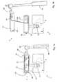
- Fig. 1 a illustrates a hood latch assembly 1 according to some embodiments comprising a first member 3 and a second member 7.
- the first member 3 is arranged to be mounted to a body member within an engine compartment of a vehicle. Such body member within an engine compartment of a vehicle may for example be a beam securely fixed onto the chassis of the vehicle or a beam forming part of the chassis of the vehicle.
- the first member 3 comprises a lock mechanism 5.
- the second member 7 is arranged to be mounted to the hood of the vehicle.
- the second member 7 comprises a striker 11 arranged to engage with the lock mechanism 5 to retain the hood of the vehicle in the closed position.
- the lock mechanism 5 may be a lock mechanism as previously known in the art.
- the lock mechanism 5 is arranged such that it can be positioned in a locking position and an unlocking position, where the lock mechanism 5 is arranged to lock the striker 11 from movement in the locking position and allow movement of the striker in a direction away from the lock mechanism 5 in the unlocking position.
- the lock mechanism 5 is arranged such that it can be displaced from the locking position to the unlocking position via a control arrangement, such as a wire, to admit opening of a vehicle hood during normal use of the hood latch assembly 1.
- a control arrangement such as a wire
- the second member 7 further comprises a hood bracket 13, arranged to be mounted to the hood of the vehicle.
- the hood bracket 13 may comprise holes for screws, bolts or rivets.
- the first member 3 may comprise holes for screws, bolts or rivets.
- the second member 7 further comprises a striker bracket 15 comprising the striker 11, and a mechanical lock 17, 21 arranged to lock the striker bracket 15 to the hood bracket 13.
- the mechanical lock 17, 21 is arranged to allow unlocking by movement of an actuator 19. Thereby, following such unlocking, movement of a vehicle hood in relation to the vehicle is allowed in a simple and reliable manner.
- the mechanical lock 17, 21 comprises a bracket locking member 21 displaceable between a first position and a second position, where the hood bracket 13 is mechanically locked to the striker bracket 15 via the mechanical lock 17, 21 when the bracket locking member 21 is in the first position, and where the hood bracket 13 is mechanically unlocked from the striker bracket 15 when the bracket locking member 21 is in the second position.
- the bracket locking member 21 is illustrated in the first position. In the embodiment shown in Fig.
- the bracket locking member 21 is provided with an aperture and the striker bracket 15 is provided with a knob 17, where the aperture of the bracket locking member 21 and the knob 17 of the striker bracket 15 are arranged such that knob 17 fits in the aperture when the bracket locking member 21 is in the first position as illustrated in Fig. 1 a to thereby lock the striker bracket 15 to the hood bracket 13.
- Fig. 1b illustrates the hood latch assembly 1 illustrated in Fig. 1 a with the bracket locking member 21 in the second position.
- the hood bracket 13 is mechanically unlocked from the striker bracket 15 when the bracket locking member 21 is in the second position. In the embodiment shown, this is due to the design of the aperture of the bracket locking member 21 and the knob 17 of the striker bracket 15.
- the bracket locking member 21 may be arranged to be displaced from the first position to the second position by movement of the actuator 19. Also, as can be seen in Fig. 1b , the actuator 19 may further be arranged to raise the hood.
- the actuator 19 may be arranged such that it displaces the bracket locking member 21 from the first position to the second position and raises the hood of the vehicle. Also, as can be seen in Fig. 1b , the knob 14 has been released from the aperture 16.
- the bracket locking member 21 may be provided with a pivot arm 22, via which it may be displaced from the first position to the second position.
- the pivot arm 22 may be provided with a pressure plate 24 against which the actuator may abut to thereby transmit movement to the bracket locking member 21, such that the bracket locking member 21 will be displaced from the first position to the second position.
- the actuator 19 may actively separate the hood bracket 13 from the striker bracket 15, such that the hood of the vehicle is raised. This may be performed by the actuator 19 exerting a force onto the pressure plate 24.
- the hood latch assembly 1 is illustrated in such a raised position.
- the mechanical lock 17, 21 may be arranged to cooperate with structural lock elements 14, 16 of the hood bracket 13 and the striker bracket 15 which are arranged to further lock the striker bracket 15 to the hood bracket 13.
- Such structural lock elements may be knob 14 arranged to fit in an aperture 16 which knob 14 is arranged to leave the aperture 16 as a result of an inclination of the hood bracket 13 in relation to the striker bracket 15 due to a force of the actuator 19.
- the hood latch assembly 1 may comprise a lift limiter 23, arranged to limit an available separation distance between the hood bracket 13 and the striker bracket 15.
- the lift limiter 23 illustrated in Fig. 1a and Fig. 2a comprises a band, which may be provided in metal or textile.
- the lift limiter may comprise a linkage for the purpose of limiting the available separation distance between the hood bracket 13 and the striker bracket 15.
- Fig. 2a illustrates the second member 7 of a hood latch assembly according to some embodiments.
- the second member 7 is arranged to be mounted to the hood of the vehicle.
- the second member 7 comprises a striker 11 arranged to engage with a lock mechanism of a first member (not shown) to retain the hood of the vehicle in the closed position.
- the second member 7 further comprises a hood bracket 13 arranged to be mounted to the hood of the vehicle.
- the hood bracket 13 may comprise holes for screws, bolts or rivets.
- the second member 7 further comprises a striker bracket 15, comprising the striker 11 and a mechanical lock 17, 21 arranged to lock the striker bracket 15 to the hood bracket 13.
- the mechanical lock 17, 21 is arranged to allow unlocking by movement of an actuator (not shown). Thereby, movement of a vehicle hood in relation to the vehicle is allowed in a simple and reliable manner.
- Fig. 2b illustrates the second member 7 of a hood latch assembly illustrated in Fig. 2a where the hood bracket 13 has been displaced in relation to the striker bracket 15.
- the mechanical lock 17, 21 comprises a bracket locking member 21 displaceable between a first position and a second position.
- the bracket locking member 21 is illustrated in the first position
- the bracket locking member 21 is illustrated in the second position.
- the hood bracket 13 is mechanically locked to the striker bracket 15 via the mechanical lock 17, 21 when the bracket locking member 21 is in the first position
- the hood bracket 13 is mechanically unlocked from the striker bracket 15 when the bracket locking member 21 is in the second position.
- the bracket locking member 21 is provided in the form of an pivotable hook arranged to extend through an aperture 17 provided in the striker bracket 15 to thereby, together with said aperture 17, form the mechanical lock 17, 21.
- the bracket locking member 21 may be biased by a spring 31 in a direction towards the first position. Thereby, the bracket locking member 21 can be retained in the first position to ensure the mechanical lock between the hood bracket 13 and the striker bracket 15.
- the bracket locking member 21 may be arranged to be displaced from the first position to the second position by the hood bracket 13 being displaced in relation to the striker bracket 15 by movement of the actuator.
- hood bracket 13 have been displaced a distance in the direction x in relation to the striker bracket 15 as compared to the hood bracket 13 illustrated in Figure 2a .
- bracket locking member 21 has been displaced from the first position to the second position.
- the hood bracket 13 is mechanically unlocked from the striker bracket 15.
- the hood bracket 13 may be separated from the striker bracket 15.
- Fig. 2c illustrates the second member 7 of a hood latch assembly where the hood bracket 13 has been separated from the striker bracket 15.
- the lift limiter 23 comprises a linkage. Such linkage may be used to control the movement of the hood even after the hood bracket 13 has been separated from the striker bracket 15 as well as limiting an available separation distance between the hood bracket 13 and the striker bracket 15.
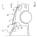
- the hood bracket 13 is displaced in relation to the striker bracket 15 via a movement of the hood. That is, one or more actuators may be arranged to displace the vehicle hood such that the hood bracket 13 is displaced in relation to the striker bracket 15 via the movement of the hood 9. Such a situation is illustrated in Fig. 3 .
- Fig. 3 illustrates an active hood latch system 25, according to some embodiments, and a vehicle 4 comprising a hood latch assembly 1, according to some embodiments, and an active hood latch system 25, according to some embodiments.
- the active hood latch system 25 comprises a hood latch assembly 1, according to some embodiments.
- the active hood latch system 25 may further comprise an actuator 19, where the actuator 19 may be arranged to, in response to a detected event, raise the hood 9 of the vehicle 4.
- a detected event may be a detection of an impending collision with a pedestrian.
- the hood 9 may be raised in a direction x essentially towards a windscreen 31 of the vehicle 4. Thereby the hood 9 may provide protection during an impact with a pedestrian.
- Such a direction x may essentially correspond to the direction x illustrated in Fig. 2a and Fig. 2b , namely a direction in which the hood bracket 13 can be displaced in relation to the striker bracket 15 in order to displace the bracket locking member 21 from the first position to the second position.
- the one or more actuators 19 may be arranged to displace the hood 9 of the vehicle 4 such that the hood bracket 13 is unlocked from the striker bracket 15. As a result, simple and reliable unlocking can be performed.
- the one or more actuators 19 may comprise one or more pyrotechnical cartridges 29. By using pyrotechnical cartridges 29, quick and reliable actuation of the actuators 19 can be performed.
- the active hood latch system 25 comprises two or more actuators 19, each comprising at least one pyrotechnical cartridge 29, where said two or more actuators 19 are arranged to raise a trailing edge 33 of the hood 9 of the vehicle 4, said trailing edge 33 facing the windshield 31 of the vehicle 4.
- an active hood latch system 25 may further comprise one or more actuators (not shown), each comprising at least one pyrotechnical cartridge, where said one or more actuators are arranged to raise a leading edge 35 of the hood 9 of the vehicle 4, said leading edge 35 essentially facing in an intended direction of travel of the vehicle 4.
- the active hood latch system 25 may comprise means to detect an impending collision with a pedestrian (not shown). Such means to detect an impending collision with a pedestrian, may, upon detection of an impending collision with a pedestrian, transmit a signal to the one or more actuators such that these are actuated. Accordingly, the "event detected” may be a detected impending collision with a pedestrian. Such means to detect an impending collision with a pedestrian may comprise one or more cameras.
Landscapes
- Engineering & Computer Science (AREA)
- Mechanical Engineering (AREA)
- Superstructure Of Vehicle (AREA)
- Chemical & Material Sciences (AREA)
- Combustion & Propulsion (AREA)
- Transportation (AREA)
Claims (12)
- Haubenverriegelungsanordnung (1), umfassend:- ein erstes Element (3), das zum Montieren an einem Körperelement innerhalb eines Motorraums eines Fahrzeugs (4) angeordnet ist, wobei das erste Element einen Verriegelungsmechanismus (5) umfasst,- ein zweites Element (7), das zum Montieren an der Haube (9) des Fahrzeugs (4) angeordnet ist und einen Schließer (11) umfasst, der zum Eingreifen in den Verriegelungsmechanismus (5) zum Halten der Haube (9) des Fahrzeugs (4) in geschlossener Position angeordnet ist, dadurch gekennzeichnet, dass das zweite Element (7) ferner umfasst:- einen Haubenbügel (13), der zum Montieren an der Haube (9) des Fahrzeugs (4) angeordnet ist,- einen Schließerbügel (15), der den Schließer (11) umfasst, und- eine mechanische Verriegelung (17, 21), die zum Verriegeln des Schließerbügels (15) am Haubenbügel (13) angeordnet ist, wobei die mechanische Verriegelung (17, 21) zum Zulassen des Entriegelns durch die Bewegung eines Aktors (19) angeordnet ist.
- Haubenverriegelungsanordnung (1) nach Anspruch 1, dadurch gekennzeichnet, dass die mechanische Verriegelung (17, 21) ein Bügelverriegelungselement (21) umfasst, das zwischen einer ersten Position und einer zweiten Position verschoben werden kann, wobei der Haubenbügel (13) mechanisch mit dem Schließerbügel (15) über die mechanische Verriegelung (17, 21) verriegelt ist, wenn das Bügelverriegelungselement (21) in der ersten Position ist, und wobei der Haubenbügel (13) mechanisch vom Schließerbügel (15) entriegelt wird, wenn das Bügelverriegelungselement (21) in der zweiten Position ist.
- Haubenverriegelungsanordnung (1) nach Anspruch 2, dadurch gekennzeichnet, dass das Bügelverriegelungselement (21) zum Verschieben von der ersten Position zu der zweiten Position durch Bewegen des Aktors (19) angeordnet ist.
- Haubenverriegelungsanordnung (1) nach Anspruch 3, dadurch gekennzeichnet, dass das Bügelverriegelungselement (21) zum Verschieben von der ersten Position zu der zweiten Position durch Verschieben des Haubenbügels (13) in Bezug auf den Schließerbügel (15) durch Bewegung des Aktors (19) angeordnet ist.
- Haubenverriegelungsanordnung (1) nach Anspruch 4, dadurch gekennzeichnet, dass der Haubenbügel (13) in Bezug auf den Schließerbügel (15) über eine Bewegung der Haube (9) verschoben wird.
- Haubenverriegelungsanordnung (1) nach einem der vorhergehenden Ansprüche, dadurch gekennzeichnet, dass ein Hubbegrenzer (23) angeordnet ist, um einen verfügbaren Trennabstand zwischen dem Haubenbügel (13) und dem Schließerbügel (15) einzuschränken.
- Haubenverriegelungsanordnung (1) nach Anspruch 6, dadurch gekennzeichnet, dass der Hubbegrenzer (23) ein Gestänge, ein textiles Band oder ein Metallband umfasst.
- Aktives Haubenverriegelungssystem (25), gekennzeichnet durch eine Haubenverriegelungsanordnung (1) nach einem der vorhergehenden Ansprüche.
- Aktives Haubenverriegelungssystem (25) nach Anspruch 8, dadurch gekennzeichnet, dass es weiterhin den Aktuator (19) umfasst, wobei der Aktor (19), als Reaktion auf ein erkanntes Ereignis zum Verschieben des Bügelverriegelungselements (21) von der ersten Position zu der zweiten Position angeordnet ist.
- Aktives Haubenverriegelungssystem (25) nach Anspruch 9, dadurch gekennzeichnet, dass der Aktor (19) eine pyrotechnische Kartusche (29) umfasst.
- Aktives Haubenverriegelungssystem (25) nach einem der Ansprüche 9 oder 10, dadurch gekennzeichnet, dass der Aktor (19) ferner zum Anheben der Haube (9) als Reaktion auf das erkannte Ereignis angeordnet ist.
- Fahrzeug (4), gekennzeichnet durch eine Haubenverriegelungsanordnung (1) nach einem der Ansprüche 1 bis 6 und/oder aktives Haubenverriegelungssystem (25) nach einem der Ansprüche 7 bis 11.
Priority Applications (3)
| Application Number | Priority Date | Filing Date | Title |
|---|---|---|---|
| EP14153276.2A EP2902272B1 (de) | 2014-01-30 | 2014-01-30 | Haubenverriegelungsanordnung |
| US14/601,567 US9476233B2 (en) | 2014-01-30 | 2015-01-21 | Hood latch assembly |
| CN201510032485.7A CN104816702B (zh) | 2014-01-30 | 2015-01-22 | 发动机罩闩锁组件 |
Applications Claiming Priority (1)
| Application Number | Priority Date | Filing Date | Title |
|---|---|---|---|
| EP14153276.2A EP2902272B1 (de) | 2014-01-30 | 2014-01-30 | Haubenverriegelungsanordnung |
Publications (2)
| Publication Number | Publication Date |
|---|---|
| EP2902272A1 EP2902272A1 (de) | 2015-08-05 |
| EP2902272B1 true EP2902272B1 (de) | 2016-07-06 |
Family
ID=50028881
Family Applications (1)
| Application Number | Title | Priority Date | Filing Date |
|---|---|---|---|
| EP14153276.2A Active EP2902272B1 (de) | 2014-01-30 | 2014-01-30 | Haubenverriegelungsanordnung |
Country Status (3)
| Country | Link |
|---|---|
| US (1) | US9476233B2 (de) |
| EP (1) | EP2902272B1 (de) |
| CN (1) | CN104816702B (de) |
Families Citing this family (20)
| Publication number | Priority date | Publication date | Assignee | Title |
|---|---|---|---|---|
| EP2907704B1 (de) * | 2014-02-18 | 2017-01-04 | Volvo Car Corporation | Anordnung mit einer pyrotechnischen Vorrichtung und einer ersten mechanischen Struktur |
| US9840858B2 (en) * | 2014-05-29 | 2017-12-12 | Ford Global Technologies, Llc | Deployable hood release handle |
| DE102015203517A1 (de) * | 2015-02-27 | 2016-09-01 | Bayerische Motoren Werke Aktiengesellschaft | Schließbügelanordnung zum wahlweisen Rückhalten oder Freigeben einer Frontklappe eines Kraftfahrzeuges |
| DE102015208392A1 (de) * | 2015-05-06 | 2016-11-10 | Bayerische Motoren Werke Aktiengesellschaft | Schließbügelanordnung zum wahlweisen Rückhalten oder rotatorischen Freigeben einer Frontklappe eines Kraftfahrzeuges |
| DE102015115665A1 (de) * | 2015-09-17 | 2017-03-23 | Kiekert Ag | Haubenverschlussvorrichtung eines Kraftfahrzeugs |
| DE102015122583A1 (de) * | 2015-12-22 | 2017-06-22 | Kiekert Ag | Sicherheitsvorrichtung für ein Kraftfahrzeug mit einer Drehfalle und einer Auswurffeder |
| JP6565764B2 (ja) * | 2016-03-30 | 2019-08-28 | 豊田合成株式会社 | アクチュエータ |
| JP2017178211A (ja) * | 2016-03-31 | 2017-10-05 | 株式会社Subaru | 車両のサイクリスト保護装置 |
| EP3243710B1 (de) * | 2016-05-11 | 2019-04-24 | Volvo Car Corporation | Motorhaubenaufstellanordnung |
| AT519051B1 (de) * | 2016-08-26 | 2018-06-15 | Hirtenberger Automotive Safety Gmbh & Co Kg | Fußgängerschutzsystem |
| CN108005497B (zh) * | 2016-10-31 | 2019-11-05 | 比亚迪股份有限公司 | 引擎罩的锁扣装置及行人保护装置 |
| DE102017114652B4 (de) * | 2017-06-30 | 2021-11-11 | Dr. Ing. H.C. F. Porsche Aktiengesellschaft | Schutzvorrichtung zum Schutz von Verkehrsteilnehmern außerhalb eines Kraftfahrzeugs und Verfahren zum Betreiben einer Schutzvorrichtung |
| US10287813B2 (en) * | 2017-07-17 | 2019-05-14 | Ford Global Technologies, Llc | Bump stop for vehicle hood |
| CN110056270B (zh) | 2017-11-21 | 2021-10-15 | 麦格纳覆盖件有限公司 | 用于主动式行人安全闩锁的双卡持件机构 |
| DE102019101992A1 (de) | 2018-01-29 | 2019-08-01 | Magna Closures Inc. | Betätigter Mechanismus für aktive Fußgänger-Sicherheitsverriegelung |
| US11066854B2 (en) | 2018-01-29 | 2021-07-20 | Magna Closures Inc. | Actuated mechanism for active pedestrian safety latch with meshed gears |
| CN110439393A (zh) | 2018-05-04 | 2019-11-12 | 麦格纳覆盖件有限公司 | 用于主动式行人安全闩锁的致动机构 |
| JP7008582B2 (ja) * | 2018-06-08 | 2022-01-25 | 本田技研工業株式会社 | 車体前部構造 |
| US20200190869A1 (en) * | 2018-12-14 | 2020-06-18 | GM Global Technology Operations LLC | Automatic vulnerable object detection triggered hood latch release |
| CN113969708B (zh) * | 2021-10-26 | 2023-04-21 | 长城汽车股份有限公司 | 锁扣结构及车辆 |
Citations (1)
| Publication number | Priority date | Publication date | Assignee | Title |
|---|---|---|---|---|
| WO2014186872A1 (en) * | 2013-05-23 | 2014-11-27 | Magna Closures Inc. | Mechanical assist mechanism for active pedestrian safety latch |
Family Cites Families (18)
| Publication number | Priority date | Publication date | Assignee | Title |
|---|---|---|---|---|
| US4917417A (en) * | 1989-02-24 | 1990-04-17 | General Motors Corporation | Hood latch assembly having unitary latching lever which functions both as a primary and secondary latch |
| US4991884A (en) * | 1990-08-01 | 1991-02-12 | General Motors Corporation | Self-presenting secondary hood latch release and hood pop-up |
| US5172945A (en) * | 1992-03-23 | 1992-12-22 | General Motors Corporation | Tri-axial support door latch |
| JP3791066B2 (ja) * | 1996-10-18 | 2006-06-28 | 日産自動車株式会社 | フード跳ね上げ装置 |
| CA2192527A1 (en) * | 1996-12-10 | 1998-06-10 | Trevor Hunt | Hood latch for an engine compartment |
| US5997230A (en) * | 1997-03-12 | 1999-12-07 | Cartridge Actuated Devices, Inc. | Plastic non-conductive explosive bolt |
| US6106033A (en) * | 1997-08-26 | 2000-08-22 | Ewald Witte Gmbh & Co. Kg | Catch-hook arrangement for a front hood or the like on motor vehicles |
| US6666483B2 (en) * | 2000-01-14 | 2003-12-23 | Atoma International Corp | Hood latch with self-retracting secondary latch release arm |
| DE102004037320A1 (de) * | 2004-08-02 | 2006-03-16 | Trw Automotive Gmbh | Vorrichtung zum Anheben eines Karosserieteils eines Kraftfahrzeugs und Verfahren zum Betreiben einer solchen Vorrichtung |
| US7845691B2 (en) * | 2006-04-05 | 2010-12-07 | Ford Global Technologies, Llc | Collision safety system for use with a motor vehicle |
| DE102006017730A1 (de) * | 2006-04-15 | 2007-10-25 | Daimlerchrysler Ag | Motorhaubenscharnier |
| JP4941401B2 (ja) * | 2008-04-28 | 2012-05-30 | 豊田合成株式会社 | アクチュエータ |
| US8505987B2 (en) * | 2009-03-17 | 2013-08-13 | GM Global Technology Operations LLC | Electrically-activated hood latch and release mechanism |
| KR101154299B1 (ko) * | 2010-09-28 | 2012-06-13 | 현대자동차주식회사 | 자동차용 액티브 후드 래치 시스템 |
| US8579068B2 (en) * | 2011-06-02 | 2013-11-12 | Ford Global Technologies, Llc | Hood latch and striker system for pedestrian protection |
| US8690591B2 (en) * | 2011-06-09 | 2014-04-08 | GM Global Technology Operations LLC | Electric vehicle with secondary charge cord release mechanism |
| US9145716B2 (en) * | 2012-05-09 | 2015-09-29 | Ford Global Technologies, Llc | Deployable hood latch for pedestrian head protection |
| CN102700497A (zh) * | 2012-06-20 | 2012-10-03 | 湖南大学 | 基于行人头部损伤防护的轿车发动机罩弹起装置 |
-
2014
- 2014-01-30 EP EP14153276.2A patent/EP2902272B1/de active Active
-
2015
- 2015-01-21 US US14/601,567 patent/US9476233B2/en active Active
- 2015-01-22 CN CN201510032485.7A patent/CN104816702B/zh active Active
Patent Citations (1)
| Publication number | Priority date | Publication date | Assignee | Title |
|---|---|---|---|---|
| WO2014186872A1 (en) * | 2013-05-23 | 2014-11-27 | Magna Closures Inc. | Mechanical assist mechanism for active pedestrian safety latch |
Also Published As
| Publication number | Publication date |
|---|---|
| CN104816702A (zh) | 2015-08-05 |
| US9476233B2 (en) | 2016-10-25 |
| CN104816702B (zh) | 2019-08-06 |
| US20150211265A1 (en) | 2015-07-30 |
| EP2902272A1 (de) | 2015-08-05 |
Similar Documents
| Publication | Publication Date | Title |
|---|---|---|
| EP2902272B1 (de) | Haubenverriegelungsanordnung | |
| US10883293B2 (en) | Hinge assembly | |
| EP1842748B1 (de) | Fahrzeug-Kollisions-Sicherheitssystem | |
| US7575273B2 (en) | Bonnet bumpstop for a vehicle | |
| US9145716B2 (en) | Deployable hood latch for pedestrian head protection | |
| US8113555B2 (en) | Vehicle impact mitigation system | |
| US10232818B2 (en) | Motor vehicle with pedestrian airbag | |
| US10118587B2 (en) | Hinge apparatus with an integrated pedestrian protection means for a front hood | |
| EP1842746B1 (de) | Motorhaube für ein Fahrzeug | |
| US20050279550A1 (en) | Hinge arrangement | |
| EP2862755B1 (de) | Fahrzeughaubensicherungsanordnung | |
| US11041329B2 (en) | Closing device for a motor vehicle hood | |
| EP2495140A1 (de) | Haubenscharnieranordnung für ein Motorfahrzeug | |
| US7416241B2 (en) | Grille and bonnet assembly for a vehicle | |
| EP2380787A1 (de) | Scharniermechanismus | |
| EP2423056B1 (de) | Sicherheitsvorrichtung | |
| US10759378B2 (en) | Protection device for protecting road users outside a motor vehicle, and method for operating a protection device | |
| EP2857266A1 (de) | Scharnieranordnung | |
| US20150107925A1 (en) | Vehicle bonnet safety assembly | |
| CN110748249B (zh) | 发动机罩锁钩及车辆 | |
| CN210049737U (zh) | 主动式发动机罩铰链机构、铰链系统以及车辆 | |
| KR100368407B1 (ko) | 자동차의 충격완충용 후드 로크장치 | |
| JP4904834B2 (ja) | 車両のフード支持構造 | |
| WO2014098078A1 (ja) | 車両 | |
| WO2014197367A1 (en) | Hinge mechanism for connecting a bonnet to a motor vehicle |
Legal Events
| Date | Code | Title | Description |
|---|---|---|---|
| PUAI | Public reference made under article 153(3) epc to a published international application that has entered the european phase |
Free format text: ORIGINAL CODE: 0009012 |
|
| 17P | Request for examination filed |
Effective date: 20140130 |
|
| AK | Designated contracting states |
Kind code of ref document: A1 Designated state(s): AL AT BE BG CH CY CZ DE DK EE ES FI FR GB GR HR HU IE IS IT LI LT LU LV MC MK MT NL NO PL PT RO RS SE SI SK SM TR |
|
| AX | Request for extension of the european patent |
Extension state: BA ME |
|
| 17P | Request for examination filed |
Effective date: 20160205 |
|
| RBV | Designated contracting states (corrected) |
Designated state(s): AL AT BE BG CH CY CZ DE DK EE ES FI FR GB GR HR HU IE IS IT LI LT LU LV MC MK MT NL NO PL PT RO RS SE SI SK SM TR |
|
| GRAP | Despatch of communication of intention to grant a patent |
Free format text: ORIGINAL CODE: EPIDOSNIGR1 |
|
| RIC1 | Information provided on ipc code assigned before grant |
Ipc: B62D 25/12 20060101ALI20160324BHEP Ipc: E05B 85/04 20140101ALI20160324BHEP Ipc: E05B 77/08 20140101ALI20160324BHEP Ipc: B60R 21/38 20110101AFI20160324BHEP Ipc: B60R 21/34 20060101ALI20160324BHEP |
|
| INTG | Intention to grant announced |
Effective date: 20160418 |
|
| GRAS | Grant fee paid |
Free format text: ORIGINAL CODE: EPIDOSNIGR3 |
|
| GRAA | (expected) grant |
Free format text: ORIGINAL CODE: 0009210 |
|
| AK | Designated contracting states |
Kind code of ref document: B1 Designated state(s): AL AT BE BG CH CY CZ DE DK EE ES FI FR GB GR HR HU IE IS IT LI LT LU LV MC MK MT NL NO PL PT RO RS SE SI SK SM TR |
|
| REG | Reference to a national code |
Ref country code: GB Ref legal event code: FG4D |
|
| REG | Reference to a national code |
Ref country code: AT Ref legal event code: REF Ref document number: 810456 Country of ref document: AT Kind code of ref document: T Effective date: 20160715 Ref country code: CH Ref legal event code: EP |
|
| REG | Reference to a national code |
Ref country code: IE Ref legal event code: FG4D |
|
| REG | Reference to a national code |
Ref country code: DE Ref legal event code: R096 Ref document number: 602014002531 Country of ref document: DE |
|
| REG | Reference to a national code |
Ref country code: SE Ref legal event code: TRGR |
|
| REG | Reference to a national code |
Ref country code: NL Ref legal event code: MP Effective date: 20160706 |
|
| REG | Reference to a national code |
Ref country code: LT Ref legal event code: MG4D |
|
| REG | Reference to a national code |
Ref country code: AT Ref legal event code: MK05 Ref document number: 810456 Country of ref document: AT Kind code of ref document: T Effective date: 20160706 |
|
| PG25 | Lapsed in a contracting state [announced via postgrant information from national office to epo] |
Ref country code: LT Free format text: LAPSE BECAUSE OF FAILURE TO SUBMIT A TRANSLATION OF THE DESCRIPTION OR TO PAY THE FEE WITHIN THE PRESCRIBED TIME-LIMIT Effective date: 20160706 Ref country code: FI Free format text: LAPSE BECAUSE OF FAILURE TO SUBMIT A TRANSLATION OF THE DESCRIPTION OR TO PAY THE FEE WITHIN THE PRESCRIBED TIME-LIMIT Effective date: 20160706 Ref country code: IS Free format text: LAPSE BECAUSE OF FAILURE TO SUBMIT A TRANSLATION OF THE DESCRIPTION OR TO PAY THE FEE WITHIN THE PRESCRIBED TIME-LIMIT Effective date: 20161106 Ref country code: HR Free format text: LAPSE BECAUSE OF FAILURE TO SUBMIT A TRANSLATION OF THE DESCRIPTION OR TO PAY THE FEE WITHIN THE PRESCRIBED TIME-LIMIT Effective date: 20160706 Ref country code: NL Free format text: LAPSE BECAUSE OF FAILURE TO SUBMIT A TRANSLATION OF THE DESCRIPTION OR TO PAY THE FEE WITHIN THE PRESCRIBED TIME-LIMIT Effective date: 20160706 Ref country code: NO Free format text: LAPSE BECAUSE OF FAILURE TO SUBMIT A TRANSLATION OF THE DESCRIPTION OR TO PAY THE FEE WITHIN THE PRESCRIBED TIME-LIMIT Effective date: 20161006 Ref country code: RS Free format text: LAPSE BECAUSE OF FAILURE TO SUBMIT A TRANSLATION OF THE DESCRIPTION OR TO PAY THE FEE WITHIN THE PRESCRIBED TIME-LIMIT Effective date: 20160706 Ref country code: IT Free format text: LAPSE BECAUSE OF FAILURE TO SUBMIT A TRANSLATION OF THE DESCRIPTION OR TO PAY THE FEE WITHIN THE PRESCRIBED TIME-LIMIT Effective date: 20160706 |
|
| PG25 | Lapsed in a contracting state [announced via postgrant information from national office to epo] |
Ref country code: LV Free format text: LAPSE BECAUSE OF FAILURE TO SUBMIT A TRANSLATION OF THE DESCRIPTION OR TO PAY THE FEE WITHIN THE PRESCRIBED TIME-LIMIT Effective date: 20160706 Ref country code: PL Free format text: LAPSE BECAUSE OF FAILURE TO SUBMIT A TRANSLATION OF THE DESCRIPTION OR TO PAY THE FEE WITHIN THE PRESCRIBED TIME-LIMIT Effective date: 20160706 Ref country code: AT Free format text: LAPSE BECAUSE OF FAILURE TO SUBMIT A TRANSLATION OF THE DESCRIPTION OR TO PAY THE FEE WITHIN THE PRESCRIBED TIME-LIMIT Effective date: 20160706 Ref country code: ES Free format text: LAPSE BECAUSE OF FAILURE TO SUBMIT A TRANSLATION OF THE DESCRIPTION OR TO PAY THE FEE WITHIN THE PRESCRIBED TIME-LIMIT Effective date: 20160706 Ref country code: GR Free format text: LAPSE BECAUSE OF FAILURE TO SUBMIT A TRANSLATION OF THE DESCRIPTION OR TO PAY THE FEE WITHIN THE PRESCRIBED TIME-LIMIT Effective date: 20161007 Ref country code: BE Free format text: LAPSE BECAUSE OF FAILURE TO SUBMIT A TRANSLATION OF THE DESCRIPTION OR TO PAY THE FEE WITHIN THE PRESCRIBED TIME-LIMIT Effective date: 20160706 Ref country code: PT Free format text: LAPSE BECAUSE OF FAILURE TO SUBMIT A TRANSLATION OF THE DESCRIPTION OR TO PAY THE FEE WITHIN THE PRESCRIBED TIME-LIMIT Effective date: 20161107 |
|
| REG | Reference to a national code |
Ref country code: DE Ref legal event code: R097 Ref document number: 602014002531 Country of ref document: DE |
|
| PG25 | Lapsed in a contracting state [announced via postgrant information from national office to epo] |
Ref country code: EE Free format text: LAPSE BECAUSE OF FAILURE TO SUBMIT A TRANSLATION OF THE DESCRIPTION OR TO PAY THE FEE WITHIN THE PRESCRIBED TIME-LIMIT Effective date: 20160706 Ref country code: RO Free format text: LAPSE BECAUSE OF FAILURE TO SUBMIT A TRANSLATION OF THE DESCRIPTION OR TO PAY THE FEE WITHIN THE PRESCRIBED TIME-LIMIT Effective date: 20160706 |
|
| PLBE | No opposition filed within time limit |
Free format text: ORIGINAL CODE: 0009261 |
|
| STAA | Information on the status of an ep patent application or granted ep patent |
Free format text: STATUS: NO OPPOSITION FILED WITHIN TIME LIMIT |
|
| PG25 | Lapsed in a contracting state [announced via postgrant information from national office to epo] |
Ref country code: SK Free format text: LAPSE BECAUSE OF FAILURE TO SUBMIT A TRANSLATION OF THE DESCRIPTION OR TO PAY THE FEE WITHIN THE PRESCRIBED TIME-LIMIT Effective date: 20160706 Ref country code: CZ Free format text: LAPSE BECAUSE OF FAILURE TO SUBMIT A TRANSLATION OF THE DESCRIPTION OR TO PAY THE FEE WITHIN THE PRESCRIBED TIME-LIMIT Effective date: 20160706 Ref country code: DK Free format text: LAPSE BECAUSE OF FAILURE TO SUBMIT A TRANSLATION OF THE DESCRIPTION OR TO PAY THE FEE WITHIN THE PRESCRIBED TIME-LIMIT Effective date: 20160706 Ref country code: BG Free format text: LAPSE BECAUSE OF FAILURE TO SUBMIT A TRANSLATION OF THE DESCRIPTION OR TO PAY THE FEE WITHIN THE PRESCRIBED TIME-LIMIT Effective date: 20161006 Ref country code: SM Free format text: LAPSE BECAUSE OF FAILURE TO SUBMIT A TRANSLATION OF THE DESCRIPTION OR TO PAY THE FEE WITHIN THE PRESCRIBED TIME-LIMIT Effective date: 20160706 |
|
| 26N | No opposition filed |
Effective date: 20170407 |
|
| PG25 | Lapsed in a contracting state [announced via postgrant information from national office to epo] |
Ref country code: SI Free format text: LAPSE BECAUSE OF FAILURE TO SUBMIT A TRANSLATION OF THE DESCRIPTION OR TO PAY THE FEE WITHIN THE PRESCRIBED TIME-LIMIT Effective date: 20160706 |
|
| REG | Reference to a national code |
Ref country code: CH Ref legal event code: PL |
|
| PG25 | Lapsed in a contracting state [announced via postgrant information from national office to epo] |
Ref country code: MC Free format text: LAPSE BECAUSE OF FAILURE TO SUBMIT A TRANSLATION OF THE DESCRIPTION OR TO PAY THE FEE WITHIN THE PRESCRIBED TIME-LIMIT Effective date: 20160706 |
|
| REG | Reference to a national code |
Ref country code: FR Ref legal event code: ST Effective date: 20170929 |
|
| PG25 | Lapsed in a contracting state [announced via postgrant information from national office to epo] |
Ref country code: LI Free format text: LAPSE BECAUSE OF NON-PAYMENT OF DUE FEES Effective date: 20170131 Ref country code: FR Free format text: LAPSE BECAUSE OF NON-PAYMENT OF DUE FEES Effective date: 20170131 Ref country code: CH Free format text: LAPSE BECAUSE OF NON-PAYMENT OF DUE FEES Effective date: 20170131 |
|
| REG | Reference to a national code |
Ref country code: IE Ref legal event code: MM4A |
|
| PG25 | Lapsed in a contracting state [announced via postgrant information from national office to epo] |
Ref country code: LU Free format text: LAPSE BECAUSE OF NON-PAYMENT OF DUE FEES Effective date: 20170130 |
|
| PG25 | Lapsed in a contracting state [announced via postgrant information from national office to epo] |
Ref country code: IE Free format text: LAPSE BECAUSE OF NON-PAYMENT OF DUE FEES Effective date: 20170130 |
|
| PG25 | Lapsed in a contracting state [announced via postgrant information from national office to epo] |
Ref country code: MT Free format text: LAPSE BECAUSE OF NON-PAYMENT OF DUE FEES Effective date: 20170130 |
|
| PG25 | Lapsed in a contracting state [announced via postgrant information from national office to epo] |
Ref country code: AL Free format text: LAPSE BECAUSE OF FAILURE TO SUBMIT A TRANSLATION OF THE DESCRIPTION OR TO PAY THE FEE WITHIN THE PRESCRIBED TIME-LIMIT Effective date: 20160706 |
|
| PGFP | Annual fee paid to national office [announced via postgrant information from national office to epo] |
Ref country code: NL Payment date: 20181221 Year of fee payment: 7 |
|
| PGFP | Annual fee paid to national office [announced via postgrant information from national office to epo] |
Ref country code: SE Payment date: 20190115 Year of fee payment: 6 |
|
| PG25 | Lapsed in a contracting state [announced via postgrant information from national office to epo] |
Ref country code: HU Free format text: LAPSE BECAUSE OF FAILURE TO SUBMIT A TRANSLATION OF THE DESCRIPTION OR TO PAY THE FEE WITHIN THE PRESCRIBED TIME-LIMIT; INVALID AB INITIO Effective date: 20140130 |
|
| PG25 | Lapsed in a contracting state [announced via postgrant information from national office to epo] |
Ref country code: CY Free format text: LAPSE BECAUSE OF FAILURE TO SUBMIT A TRANSLATION OF THE DESCRIPTION OR TO PAY THE FEE WITHIN THE PRESCRIBED TIME-LIMIT Effective date: 20160706 |
|
| PG25 | Lapsed in a contracting state [announced via postgrant information from national office to epo] |
Ref country code: MK Free format text: LAPSE BECAUSE OF FAILURE TO SUBMIT A TRANSLATION OF THE DESCRIPTION OR TO PAY THE FEE WITHIN THE PRESCRIBED TIME-LIMIT Effective date: 20160706 |
|
| PG25 | Lapsed in a contracting state [announced via postgrant information from national office to epo] |
Ref country code: TR Free format text: LAPSE BECAUSE OF FAILURE TO SUBMIT A TRANSLATION OF THE DESCRIPTION OR TO PAY THE FEE WITHIN THE PRESCRIBED TIME-LIMIT Effective date: 20160706 |
|
| REG | Reference to a national code |
Ref country code: SE Ref legal event code: EUG |
|
| GBPC | Gb: european patent ceased through non-payment of renewal fee |
Effective date: 20200130 |
|
| REG | Reference to a national code |
Ref country code: SE Ref legal event code: EUG |
|
| PG25 | Lapsed in a contracting state [announced via postgrant information from national office to epo] |
Ref country code: GB Free format text: LAPSE BECAUSE OF NON-PAYMENT OF DUE FEES Effective date: 20200130 Ref country code: SE Free format text: LAPSE BECAUSE OF NON-PAYMENT OF DUE FEES Effective date: 20200131 |
|
| P01 | Opt-out of the competence of the unified patent court (upc) registered |
Effective date: 20231212 |
|
| PGFP | Annual fee paid to national office [announced via postgrant information from national office to epo] |
Ref country code: DE Payment date: 20231219 Year of fee payment: 11 |