EP2902130A1 - Umformwerkzeug mit lochstempel - Google Patents
Umformwerkzeug mit lochstempel Download PDFInfo
- Publication number
- EP2902130A1 EP2902130A1 EP15153777.6A EP15153777A EP2902130A1 EP 2902130 A1 EP2902130 A1 EP 2902130A1 EP 15153777 A EP15153777 A EP 15153777A EP 2902130 A1 EP2902130 A1 EP 2902130A1
- Authority
- EP
- European Patent Office
- Prior art keywords
- punch
- forming tool
- movement
- tool according
- forming
- Prior art date
- Legal status (The legal status is an assumption and is not a legal conclusion. Google has not performed a legal analysis and makes no representation as to the accuracy of the status listed.)
- Granted
Links
- 238000002407 reforming Methods 0.000 title 1
- 229910000831 Steel Inorganic materials 0.000 claims description 2
- 239000010959 steel Substances 0.000 claims description 2
- 238000004080 punching Methods 0.000 description 6
- 238000003860 storage Methods 0.000 description 4
- 230000008878 coupling Effects 0.000 description 3
- 238000010168 coupling process Methods 0.000 description 3
- 238000005859 coupling reaction Methods 0.000 description 3
- 238000007667 floating Methods 0.000 description 3
- 238000004519 manufacturing process Methods 0.000 description 3
- 239000000463 material Substances 0.000 description 3
- 238000000034 method Methods 0.000 description 3
- 230000008569 process Effects 0.000 description 3
- 238000009966 trimming Methods 0.000 description 3
- 230000008901 benefit Effects 0.000 description 2
- 238000005520 cutting process Methods 0.000 description 2
- 239000002184 metal Substances 0.000 description 2
- 229910052751 metal Inorganic materials 0.000 description 2
- 239000007769 metal material Substances 0.000 description 2
- 238000007493 shaping process Methods 0.000 description 2
- 229910000797 Ultra-high-strength steel Inorganic materials 0.000 description 1
- 230000000295 complement effect Effects 0.000 description 1
- 238000001816 cooling Methods 0.000 description 1
- 238000005336 cracking Methods 0.000 description 1
- 230000003111 delayed effect Effects 0.000 description 1
- 230000001419 dependent effect Effects 0.000 description 1
- 230000017525 heat dissipation Effects 0.000 description 1
- 238000010438 heat treatment Methods 0.000 description 1
- 238000007654 immersion Methods 0.000 description 1
- 230000003993 interaction Effects 0.000 description 1
- 238000012423 maintenance Methods 0.000 description 1
- 229910000734 martensite Inorganic materials 0.000 description 1
- 238000000465 moulding Methods 0.000 description 1
- 230000035515 penetration Effects 0.000 description 1
- 210000003899 penis Anatomy 0.000 description 1
- BASFCYQUMIYNBI-UHFFFAOYSA-N platinum Chemical group [Pt] BASFCYQUMIYNBI-UHFFFAOYSA-N 0.000 description 1
- 238000004064 recycling Methods 0.000 description 1
- 230000008439 repair process Effects 0.000 description 1
- 230000009466 transformation Effects 0.000 description 1
- 238000003466 welding Methods 0.000 description 1
Images



Classifications
-
- B—PERFORMING OPERATIONS; TRANSPORTING
- B21—MECHANICAL METAL-WORKING WITHOUT ESSENTIALLY REMOVING MATERIAL; PUNCHING METAL
- B21J—FORGING; HAMMERING; PRESSING METAL; RIVETING; FORGE FURNACES
- B21J13/00—Details of machines for forging, pressing, or hammering
- B21J13/08—Accessories for handling work or tools
- B21J13/085—Accessories for handling work or tools handling of tools
-
- B—PERFORMING OPERATIONS; TRANSPORTING
- B21—MECHANICAL METAL-WORKING WITHOUT ESSENTIALLY REMOVING MATERIAL; PUNCHING METAL
- B21D—WORKING OR PROCESSING OF SHEET METAL OR METAL TUBES, RODS OR PROFILES WITHOUT ESSENTIALLY REMOVING MATERIAL; PUNCHING METAL
- B21D28/00—Shaping by press-cutting; Perforating
- B21D28/24—Perforating, i.e. punching holes
- B21D28/32—Perforating, i.e. punching holes in other articles of special shape
- B21D28/325—Perforating, i.e. punching holes in other articles of special shape using cam or wedge mechanisms, e.g. aerial cams
-
- B—PERFORMING OPERATIONS; TRANSPORTING
- B21—MECHANICAL METAL-WORKING WITHOUT ESSENTIALLY REMOVING MATERIAL; PUNCHING METAL
- B21D—WORKING OR PROCESSING OF SHEET METAL OR METAL TUBES, RODS OR PROFILES WITHOUT ESSENTIALLY REMOVING MATERIAL; PUNCHING METAL
- B21D28/00—Shaping by press-cutting; Perforating
- B21D28/24—Perforating, i.e. punching holes
- B21D28/36—Perforating, i.e. punching holes using rotatable work or tool holders
-
- B—PERFORMING OPERATIONS; TRANSPORTING
- B21—MECHANICAL METAL-WORKING WITHOUT ESSENTIALLY REMOVING MATERIAL; PUNCHING METAL
- B21D—WORKING OR PROCESSING OF SHEET METAL OR METAL TUBES, RODS OR PROFILES WITHOUT ESSENTIALLY REMOVING MATERIAL; PUNCHING METAL
- B21D35/00—Combined processes according to or processes combined with methods covered by groups B21D1/00 - B21D31/00
- B21D35/001—Shaping combined with punching, e.g. stamping and perforating
-
- B—PERFORMING OPERATIONS; TRANSPORTING
- B21—MECHANICAL METAL-WORKING WITHOUT ESSENTIALLY REMOVING MATERIAL; PUNCHING METAL
- B21J—FORGING; HAMMERING; PRESSING METAL; RIVETING; FORGE FURNACES
- B21J13/00—Details of machines for forging, pressing, or hammering
- B21J13/02—Dies or mountings therefor
-
- B—PERFORMING OPERATIONS; TRANSPORTING
- B21—MECHANICAL METAL-WORKING WITHOUT ESSENTIALLY REMOVING MATERIAL; PUNCHING METAL
- B21J—FORGING; HAMMERING; PRESSING METAL; RIVETING; FORGE FURNACES
- B21J5/00—Methods for forging, hammering, or pressing; Special equipment or accessories therefor
- B21J5/02—Die forging; Trimming by making use of special dies ; Punching during forging
- B21J5/025—Closed die forging
-
- B—PERFORMING OPERATIONS; TRANSPORTING
- B21—MECHANICAL METAL-WORKING WITHOUT ESSENTIALLY REMOVING MATERIAL; PUNCHING METAL
- B21J—FORGING; HAMMERING; PRESSING METAL; RIVETING; FORGE FURNACES
- B21J9/00—Forging presses
- B21J9/02—Special design or construction
-
- B—PERFORMING OPERATIONS; TRANSPORTING
- B21—MECHANICAL METAL-WORKING WITHOUT ESSENTIALLY REMOVING MATERIAL; PUNCHING METAL
- B21K—MAKING FORGED OR PRESSED METAL PRODUCTS, e.g. HORSE-SHOES, RIVETS, BOLTS OR WHEELS
- B21K7/00—Making railway appurtenances; Making vehicle parts
- B21K7/12—Making railway appurtenances; Making vehicle parts parts for locomotives or vehicles, e.g. frames, underframes
Definitions
- the present invention relates to a forming tool with a punch according to the features in the preamble of claim 1.
- sheet metal components are used in particular in automotive engineering as body structure components or even body shell components.
- metallic materials in particular steel materials, are provided in platinum form, wherein the boards are then inserted into molds and formed by appropriate press forming.
- a press tool has an upper tool and a lower tool, wherein upper tool and lower tool perform a vertical movement and then a mold cavity remains between upper tool and lower tool, which gives the board a corresponding three-dimensional contour.
- the hot forming and Presshärttechnologie is known in which the board is heated to over Austenitmaschinestemperatur before heating, so to more than 850 ° C, so that austenitization has taken place.
- the board is then reformed in the warm state, since it has high shaping degrees of freedom with relatively low forming forces to be applied in this state.
- the board is cooled or quenched so fast that a transformation of the austenitic microstructure into martensitic microstructure is created and thus a significantly higher strength or hardness properties are set. A risk of delayed cracking or the occurrence of microcracks as hard cutting is thus avoided.
- Object of the present invention is therefore, starting from the prior art to show a forming tool, with which it is possible, regardless of the wall thickness of the component to be manufactured and / or the state of wear of the forming tool to perform perforations with high precision.
- the forming tool for press-forming a circuit board has an upper tool and a lower tool, wherein with closed forming tool between the upper tool and lower tool remains a mold cavity and a relatively movable relative to the forming tool in a direction of movement punch is provided, which is retractable at least in the mold cavity and the punch puncture is mounted with at least one degree of freedom of movement, wherein the degree of freedom of movement is oriented transversely to the direction of movement of the punch.
- the punch is pivotally mounted on a foot area.
- the punch in the direction of movement thus the movement that is performed for punching, is mounted so that it is not displaced, so that the hole force required for perforation is transmitted in the direction of movement essentially in a slide-rigid manner.
- an end or stamp head is mounted with at least one degree of freedom of movement, which extends transversely to the direction of movement.
- This is realized according to the invention by a foot region of the punch with a roller body or cylinder or alternatively with a ball head is mounted in each case pivotally. This pivotable bearing thus transmits in the direction of movement the required hole force substantially parallel to the slide and at the same time allows the shaft of the punch and in particular the punch head to move transversely to the direction of movement with at least one degree of freedom.
- a particularly preferred embodiment is the storage by means of a ball head, which can also be referred to as cardanic storage.
- a ball head which can also be referred to as cardanic storage.
- the punch would rotate about its own axis, which is undesirable especially for non-circular head ends.
- the invention provides that an anti-rotation, in particular in the form of a Vermosommes forestes, by the ball head, in particular the center of the ball of the ball head cutting, is guided, so that two pin extensions each protrude at opposite ends of the ball head.
- the ball head itself is then mounted in a ball socket, wherein grooves are provided in the ball socket, in which engage the pin extensions of the anti-rotation pin.
- These grooves with the pin extensions each form a floating bearing with a translatory degree of freedom, so that the punch can not rotate about its longitudinal axis, but the punch head is pivotally pivotable within the predetermined enveloping circle.
- the punch is elastically mounted so that it is in the initial state or state of rest, thus state before contact with the sheet to be punched, in a centering or zero position.
- the head end can then leave this centering position due to the pivotal mounting and perform the perforation. After performed perforation and pulling out the punch from the hole produced this is returned to its centered position due to the elastic storage.
- the forming tool according to the invention is designed in particular as a hot-forming and press-hardening tool.
- the forming tool is operated in series production, the forming tool itself is subject to abrasive wear and / or inaccuracies in the components due to components with different wall thicknesses Plant area between the upper tool and the board as well as the board and lower tool, in particular in the area of the punch.
- the punches penetrate at least partially, in particular completely, into the mold cavity and very particularly preferably pass through the latter and thereby perform the perforation.
- the expelled material can then be taken up in a region opposite the punch or else via a corresponding discharge channel then directly discharge the perforated cutout.
- at least one further degree of freedom of movement of the punch is provided, which is arranged transversely to the direction of movement of the actual hole process.
- the punch is thus given a tolerance compensation possibility, so that this still performs the perforation and at the same time not jammed.
- the elastic bearing is thus formed substantially in the radial direction of the punch.
- the punch may be elastically supported only in a radial direction, alternatively be elastically mounted in two opposite radial directions or be mounted radially circumferentially elastic.
- this tolerance compensation is inventively formed by a radial elastic bearing in conjunction with a chamfer on the punch head of the punch and a corresponding counter chamfer or inner bevel on the hole of the punch opposite tool, in which the punch enters.
- a corresponding tolerance compensation thus takes place during execution of the movement in the direction of movement for punching in such a way that the punch passes through the board and centering takes place due to bevel to the opposite Lochmatrize.
- the return movement of the punch in its initial position is done by the radially encircling elastic mounting.
- the punch can also be tapered towards its free end be educated.
- the free end is then formed smaller with its outer radius than an inner radius of a corresponding opening into which the punch enters.
- a self-centering would then be carried out in conjunction with the radial bearing.
- holes can thus be made in a component within a forming tool, regardless of the state of wear of the forming tool and / or possible inaccuracies in the contact of the circuit board within the mold cavity, in particular due to different wall thicknesses and / or complex degrees of deformation.
- the punch not only carries out a movement in the tool closing direction thus decisive vertical direction performing movement, but can perform a hole movement in each oriented angle and in particular performs a hole movement in the horizontal direction.
- the punch is mounted in particular on a carriage, wherein the carriage is preferably movable by a third drive source relative to the forming tool.
- the punch is mounted in the upper tool or in the lower tool, so that the drive source then moves the punch relative to the upper tool or the lower tool.
- the drive source itself is mechanically, electrically, hydraulically or pneumatically formed. In the context of the invention, in particular a servo drive or even a hydraulic drive is used.
- the punch is fixed to the carriage in such a way that it is coupled to the carriage at a foot area in the direction of movement in a sliding manner.
- the rigid coupling takes place via a cylinder or a ball head, each according to the principle of a plain bearing.
- the punch a pivoting movement by at least a few Performs degree around the cylinder axis.
- the punch can perform a rotating pivotal movement about the ball head.
- the punch is formed as an elongated extension and radially elastically mounted toward its head end. In particular, this storage is carried out by elastic bearing rings, which are pushed onto the punch and / or this include radially.
- the bearing rings themselves are interchangeable, so that a corresponding maintenance of the punch is possible.
- the bearing rings are arranged in a cavity of the carriage and secured against axial movement with a locking ring, such as a snap ring or a cap.
- the bearing rings are formed in the context of the invention, in particular from a temperature-resistant material, so that they withstand at least for a short time temperatures above 200 ° C or more.
- radially acting spring elements are arranged on the punch in the radial direction, which then take over the elastic mounting of the punch.
- the spring elements are formed of a metallic material, so that they are temperature-stable to temperatures above 200 ° C, in particular above 500 ° C.
- the punch still has a bevel on his head.
- Complementary to the chamfer has the opposite region of the forming tool, in particular a region on the lower tool in the event that the punch is mounted on the upper tool relatively movable, an inner bevel on.
- the punch thus moves into the réellefase and behind it opening for performing the hole movement.
- an exchangeable perforated plate hereinafter also referred to as a perforated die, is particularly preferably provided.
- the hole and the inner bevel can be embedded directly in the tool or the mold surface. However, when a series production is carried out, such a lending may occur that the molding tool is still in an acceptable state, but the inner bevel and the opening behind it would require a revision.
- the present invention provides that a perforated plate is arranged in the region of the recess and the perforated plate is exchangeable. This can on the one hand the Wear and thus laborious welding on the lower tool during repair can be prevented, however, it can also be done by replacing the perforated plate with a different positioning of the hole readjustment for the hole process.
- the perforated plate itself is in turn cooled or designed to be coolable.
- the perforated plate is sealingly arranged on a corresponding cooling channel of the lower tool or coupled thereto, so that also here a heat dissipation through the perforated plate is made possible.
- high-strength or ultrahigh-strength steel blanks are converted into a motor vehicle component by means of hot forming and press hardening.
- the perforation itself takes place in particular before the actual curing process of the board or the molded component.
- FIG. 1 shows an inventive forming tool 1, comprising an upper tool 2 and a lower tool 3 in the open state. Between upper tool 2 and lower tool 3, a board 4 is inserted. When executing a closing movement in the vertical direction 5 is formed between the upper tool 2 and lower tool 3, a mold cavity 7, which gives the board 4, the desired shape. Further, in the upper tool 2, a punch assembly 6 is provided, which is mounted in the direction of movement B movable to the upper tool 2. The direction of movement B is carried out substantially horizontally, whereas the closing movement of the upper tool 2 in the vertical direction 5 is performed. The punch assembly is movably mounted in a carriage guide 23, so that it is displaceable in the direction of movement B.
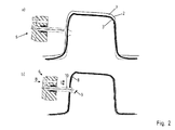
- FIG. 2 a) and b) show a detailed view with closed forming tool.
- the forming tool 1 is almost completely closed and in FIG. 2 b) this is completely closed and the punch assembly 6 has made the relative movement in the direction of movement for performing the perforation.
- the resulting mold cavity 7 between the upper tool 2 and lower tool 3, wherein it at FIG. 2 b) It can be clearly seen that inaccuracies, for example remaining cavities 8, can occur when the forming tool 1 is completely closed.
- the punch 10 is coupled to a sliding slide 11 in the direction of movement B of the punch assembly 6.
- This rigid coupling in the foot region 12 of the punch 10 is realized by a ball head 13 or a cylinder.
- a pivoting movement S or in the case of a ball head 13 a three-dimensional pivotal movement S is performed at the same time schubstarrer coupling in the direction of movement B.
- the punch 10 can be pivoted by a few degrees at an angle ⁇ .
- an anti-rotation pin 14 is additionally preferably arranged so that the punch 10 does not rotate about its longitudinal axis L, but only the pivoting movement S executes.
- the elastic support rings 15 are in turn secured by a locking ring 16 in the axial direction.
- the securing ring 16 also has an opening 17, which can serve as a boundary, so that in the case of positive contact between the punch 10 and the opening 17 there is a limitation of the pivoting movement S in the radial direction R.
- an exchangeable perforated plate 21 is preferably provided in the schematically indicated lower tool 3, an inner bevel 22 being formed on the perforated plate 21 or at the inlet of the opening 20 in the perforated plate 21.
- FIG. 5 a) and b) show the punch 10 and ball head 13 in a respective sectional view.
- the punch 10 has for this purpose a ball head 13, which is located on the foot portion 12 of the punch 10.
- the ball head 13 is mounted pivotably or rotatably in a ball socket 24.
- Extending laterally relative to the ball head 13 extend the pin extensions 25 of the anti-rotation pin 14, wherein these are designed such that an axis connecting them passes through the center M of the ball head 13.
- the pin extensions 25 are arranged in each case one opposite the ball socket 24 recessed groove 26.
- the grooves 26 are formed such that they form in cooperation with the pin extensions 25 a floating bearing with an axial or translatory degree of freedom. This is clearly visible in FIG.
- FIG. 5 b) shows the cross section bb FIG. 5a ).
- the punch head 18 can thereby make a movement out of FIG. 6 is clearly visible.
- position Pos 1 the punch head 18 is in the rest position or in the centered position, so that its longitudinal axis L is centered in the center. If the stamp head 18 now executes the pivoting movement, this is possible both in the direction of movement X and in the direction of movement Y. as well as any resulting intermediate position.
- the opening 17 of the locking ring 16 the movement is positively limited in case of positive contact of the shaft 29 with an inner circumferential surface 30 of the opening 17, shown in FIG FIG. 5 a) ,
- the shaft 29 and the opening 17 are each formed circular.
- an envelope 31 which limits the outer movement of the punch head 18 and is shown here as a boundary circle or enveloping circle 31 for the movement space 32 of a center point 33 by the longitudinal axis L leaves the punch head 18.
- the positions Pos 2, Pos 3 and Pos 4 are shown, wherein any intermediate position due to the pivotal mounting of the foot portion 12 in connection with the limitation by the inner circumferential surface 30 of the opening 17 is ingestible and each of the center point 33 is disposed within the enveloping circle 31 ,
- FIG. 7 a) to d) show different end views of the punch head 18.
- this is quadrangular, in particular rectangular.
- the stamp head 18 is triangular and in the case of FIG. 7c ), the punch head 18 is oval and formed in FIG. 7 d ) as a polygon with inward and outward-running corners.
- the shaft 29 may then also have the respective shape of the front view or be formed round.
Landscapes
- Engineering & Computer Science (AREA)
- Mechanical Engineering (AREA)
- Shaping Metal By Deep-Drawing, Or The Like (AREA)
- Perforating, Stamping-Out Or Severing By Means Other Than Cutting (AREA)
Abstract
Description
- Die vorliegende Erfindung betrifft ein Umformwerkzeug mit Lochstempel gemäß den Merkmalen im Oberbegriff von Patentanspruch 1.
- Aus dem Stand der Technik ist es bekannt, Blechbauteile durch Pressumformen herzustellen. Diese Blechbauteile werden insbesondere in der Kraftfahrzeugtechnik eingesetzt als Karosseriestrukturbauteile oder aber auch Karosserieaußenhautbauteile. Hierzu werden metallische Werkstoffe, insbesondere Stahlwerkstoffe, in Platinenform bereitgestellt, wobei die Platinen dann in Pressformwerkzeuge eingelegt werden und durch entsprechendes Pressumformen umgeformt werden. Hierzu weist ein Pressformwerkzeug ein Oberwerkzeug und ein Unterwerkzeug auf, wobei Oberwerkzeug und Unterwerkzeug eine Vertikalbewegung durchführen und dann zwischen Oberwerkzeug und Unterwerkzeug ein Formhohlraum verbleibt, welcher der Platine eine entsprechende dreidimensionale Kontur verleiht.
- Aus dem Stand der Technik ist insbesondere die Warmumform- und Presshärttechnologie bekannt, bei der die Platine vor der Erwärmung auf über Austenitisierungstemperatur, mithin auf mehr als 850 °C aufgeheizt wird, so dass eine Austenitisierung stattgefunden hat. Die Platine wird dann im warmen Zustand umgeformt, da sie in diesem Zustand hohe Formgebungsfreiheitsgrade bei in Relation gering aufzubringenden Umformkräften besitzt. Im Anschluss daran wird die Platine derart schnell abgekühlt bzw. abgeschreckt, dass eine Umwandlung des austenitischen Gefüges in martensitisches Gefüge entsteht und hierdurch dann eine deutlich höhere Festigkeit bzw. Härteeigenschaften eingestellt werden. Eine Gefahr verzögerter Rissbildung oder das Auftreten von Mikrorissen wie beim Hartschneiden wird so vermieden.
- Es sind mitunter jedoch nicht nur Formgebungsoperationen, sondern auch Lochungs- oder aber Beschnittoperationen vor der Härtung durchzuführen, da der Einsatz der Kräfte zum Lochen oder aber Beschneiden sowie der Verschleiß der Loch- oder aber Beschnittwerkzeuge hier geringer sind als bei einem gehärteten Bauteil.
- In ein entsprechendes Bauteil müssen insbesondere derart Ausnehmungen oder Löcher eingebracht werden, so dass Schraubverbindungen hergestellt werden können oder aber auch Kabeldurchführungen stattfinden können. Um solche Ausnehmungen an einem Bauteil herzustellen, sind entsprechende Lochstempel aus dem Stand der Technik bekannt. Beispielsweise ist ein kombiniertes Umform- und Lochwerkzeug aus der
DE 10 2008 034 996 B4 bekannt. Hierbei wird mit dem Umformen selber eine entsprechende Lochoperation durchgeführt. - Kommen nunmehr dreidimensional komplex geformte Bauteile zum Einsatz oder aber Bauteile mit voneinander verschiedenen Wandstärken, so kommt es in dem Formhohlraum mitunter zu unpräzisem Anlagenkontakt gerade im Bereich des Lochstempels zwischen Oberwerkzeug und Unterwerkzeug sowie der dazwischen befindlichen bereits weitgehend ausgeformten Platine.
- Aufgabe der vorliegenden Erfindung ist es daher, ausgehend vom Stand der Technik, ein Umformwerkzeug aufzuzeigen, mit dem es möglich ist, unabhängig von den Wanddicken des herzustellenden Bauteils und/oder dem Verschleißzustand des Umformwerkzeuges, Lochungen mit hoher Präzision durchzuführen.
- Die zuvor genannte Aufgabe wird erfindungsgemäß mit einem Umformwerkzeug gemäß den Merkmalen im Patentanspruch 1 gelöst.
- Vorteilhafte Ausführungsvarianten sind Gegenstand der abhängigen Patentansprüche.
- Das Umformwerkzeug zum Pressumformen einer Platine weist ein Oberwerkzeug und ein Unterwerkzeug auf, wobei bei geschlossenem Umformwerkzeug zwischen Oberwerkzeug und Unterwerkzeug ein Formhohlraum verbleibt und ein relativ gegenüber dem Umformwerkzeug in einer Bewegungsrichtung verfahrbarer Lochstempel vorgesehen ist, der zumindest in den Formhohlraum einfahrbar ist und der Lochstempel elastisch mit mindestens einem Bewegungsfreiheitsgrad gelagert ist, wobei der Bewegungsfreiheitsgrad quer zur Bewegungsrichtung des Lochstempels orientiert ist. Erfindungsgemäß ist vorgesehen, dass der Lochstempel an einem Fußbereich schwenkbar gelagert ist.
- Dies bedeutet im Rahmen der Erfindung, dass der Lochstempel in Bewegungsrichtung, mithin der Bewegung, die zum Lochen ausgeführt wird, verschiebefest gelagert ist, so dass die zur Lochung erforderliche Lochkraft in Bewegungsrichtung im Wesentlichen schubstarr übertragen wird. Quer zur Bewegungsrichtung ist jedoch insbesondere ein Ende bzw. Stempelkopf gelagert mit mindestens einem Bewegungsfreiheitsgrad, welcher sich quer zur Bewegungsrichtung erstreckt. Dies wird erfindungsgemäß realisiert, indem ein Fußbereich des Lochstempels mit einem Walzenkörper bzw. Zylinder oder alternativ mit einem Kugelkopf jeweils schwenkbar gelagert ist. Diese schwenkbare Lagerung überträgt somit in Bewegungsrichtung die erforderliche Lochkraft im Wesentlichen schubstarr und lässt es gleichzeitig zu, dass sich der Schaft des Stempels und insbesondere der Stempelkopf mit mindestens einem Freiheitsgrad quer zur Bewegungsrichtung bewegen kann.
- Eine besonders bevorzugte Ausführungsvariante ist dabei die Lagerung mittels Kugelkopf, welche auch als kardanische Lagerung bezeichnet werden kann. Diese ermöglicht es dem Stempelkopf, sich in zwei translatorische Richtungen jeweils quer zur Bewegungsrichtung zu bewegen und somit jegliche Position in einem vorgegeben Raum, insbesondere nachfolgend als Hüllraum bezeichnet, einzunehmen. Der Stempelkopf bewegt sich folglich in einem Hüllkreis.
- Darüber hinaus würde sich jedoch der Lochstempel um seine eigene Achse drehen, was insbesondere bei nicht kreisrunden Kopfenden unerwünscht ist. Dazu ist erfindungsgemäß vorgesehen, dass eine Verdrehsicherung, insbesondere in Form eines Verdrehsicherungsstiftes, durch den Kugelkopf, insbesondere den Mittelpunkt der Kugel des Kugelkopfes schneidend, geführt ist, so dass zwei Stiftfortsätze jeweils an gegenüberliegenden Enden von dem Kugelkopf abstehen. Der Kugelkopf selbst ist dann in einer Kugelpfanne gelagert, wobei in der Kugelpfanne Nuten vorgesehen sind, in die die Stiftfortsätze des Verdrehsicherungsstiftes eingreifen. Diese Nuten mit den Stiftfortsätzen bilden je ein Loslager mit einem translatorischen Freiheitsgrad aus, so dass sich der Stempel nicht um seine Längsachse rotieren kann, jedoch der Stempelkopf schwenkbar innerhalb des vorgegebenen Hüllkreises verschwenkbar ist. Beispielsweise bei einer viereckigen oder dreieckigen vorzunehmenden Lochung ist somit jeweils eine korrekte Einstellung des Lochbildes sichergestellt dadurch, dass sich der Stempelkopf nicht um die Längsachse des Stempels dreht, wobei mit dem Lochstempel auf Produktionstoleranzen reagiert werden kann.
- Insbesondere ist der Lochstempel derart elastisch gelagert, dass er sich im Ausgangszustand bzw. Ruhezustand, mithin Zustand vor Kontakt mit dem zu lochenden Blech, in einer Zentrierposition bzw. Nullposition befindet. Bei Kontakt mit dem Blech kann dann das Kopfende diese Zentrierposition aufgrund der schwenkbaren Lagerung verlassen und die Lochung durchführen. Nach durchgeführter Lochung und Herausziehen des Lochstempels aus dem hergestellten Loch wird dieser wieder in seine zentrierte Lage aufgrund der elastischen Lagerung zurückgeführt. Das erfindungsgemäße Umformwerkzeug ist insbesondere als Warmumform- und Presshärtwerkzeug ausgebildet. Wird nunmehr das Umformwerkzeug in einer Serienfertigung betrieben, so unterliegt zum einen das Umformwerkzeug selber einem abrasiven Verschleiß und/oder es kommt aufgrund von Bauteilen mit unterschiedlicher Wandstärke zu Ungenauigkeiten im Anlagenbereich zwischen Oberwerkzeug und Platine sowie Platine und Unterwerkzeug, insbesondere im Bereich des Lochstempels.
- Erfindungsgemäß ist nunmehr vorgesehen, dass der Lochstempel zumindest teilweise, insbesondere vollständig in den Formhohlraum einfährt und ganz besonders bevorzugt diesen durchfährt und dabei die Lochung durchführt. Das ausgetriebene Material kann dann in einem dem Lochstempel gegenüberliegenden Bereich aufgenommen werden oder aber auch über einen entsprechenden Abführkanal dann den gelochten Ausschnitt direkt abführen. Kommt es zu einer derartigen Ungenauigkeit, dass beim Anfahren eines aus dem Stand der Technik bekannten Lochstempels ein Verklemmen stattfinden würde, so ist erfindungsgemäß vorgesehen, dass mindestens ein weiterer Bewegungsfreiheitsgrad des Lochstempels vorgesehen ist, der quer zur Bewegungsrichtung des eigentlichen Lochvorganges angeordnet ist. Dem Lochstempel wird somit eine Toleranzausgleichmöglichkeit gegeben, so dass dieser dennoch die Lochung durchführt und gleichzeitig selbst nicht verklemmt. Die elastische Lagerung wird somit im Wesentlichen in Radialrichtung des Lochstempels ausgebildet. Dabei kann der Lochstempel nur in eine Radialrichtung elastisch gelagert sein, alternativ in zwei gegenüberliegende Radialrichtungen elastisch gelagert sein oder aber radial umlaufend elastisch gelagert sein.
- Insbesondere ist dieser Toleranzausgleich erfindungsgemäß durch eine radiale elastische Lagerung ausgebildet in Verbindung mit einer Fase an dem Stempelkopf des Lochstempels sowie einer entsprechenden Gegenfase bzw. Innenfase an dem Loch des dem Lochstempel gegenüberliegenden Werkzeuges, in das der Lochstempel einfährt. Ein entsprechender Toleranzausgleich findet somit bei Ausführung der Bewegung in Bewegungsrichtung zum Lochen derart statt, dass der Lochstempel durch die Platine hindurchfährt und aufgrund von Fase eine Zentrierung zur gegenüberliegenden Lochmatrize stattfindet. Die Rückbewegung des Lochstempels in seine Ausgangslage erfolgt durch die radial umlaufend elastische Lagerung. Im Rahmen der Erfindung ist es auch möglich, dass nur der Lochstempel eine Fase aufweist oder alternativ das Loch, in das der Lochstempel auf der gegenüberliegenden Seite einfährt, eine entsprechende Innenfase aufweist. Alternativ kann der Lochstempel auch zu seinem freien Ende hin verjüngt ausgebildet sein. Insbesondere ist das freie Ende dann mit seinem Außenradius kleiner ausgebildet als ein Innenradius einer korrespondierenden Öffnung, in die der Lochstempel einfährt. Auch hierdurch würde dann eine Eigenzentrierung in Verbindung mit der radialen Lagerung ausgeführt werden.
- Im Ergebnis können somit Lochungen in einem Bauteil innerhalb eines Umformwerkzeuges durchgeführt werden, unabhängig von dem Verschleißzustand des Umformwerkzeuges und/oder eventueller Ungenauigkeiten des Anlagenkontaktes der Platine innerhalb des Formhohlraumes, insbesondere bedingt durch voneinander verschiedene Wandstärken und/oder komplexe Umformgrade.
- Ein weiterer wesentlicher Vorteil ist, dass insbesondere der Lochstempel nicht nur eine in Werkzeugschließrichtung mithin maßgeblichen Vertikalrichtung ausführende Bewegung durchführt, sondern in jedem dazu orientierten Winkel eine Lochbewegung durchführen kann und insbesondere eine Lochbewegung in Horizontalrichtung durchführt. Dazu ist der Lochstempel insbesondere auf einem Schlitten gelagert, wobei der Schlitten bevorzugt von einer dritten Antriebsquelle relativ zu dem Umformwerkzeug verfahrbar ist. Insbesondere ist der Lochstempel in dem Oberwerkzeug oder in dem Unterwerkzeug gelagert, so dass die Antriebsquelle dann den Lochstempel relativ gegenüber dem Oberwerkzeug oder aber dem Unterwerkzeug verfährt. Die Antriebsquelle selbst ist mechanisch, elektrisch, hydraulisch oder aber auch pneumatisch ausgebildet. Im Rahmen der Erfindung wird insbesondere ein Servoantrieb oder aber auch ein Hydraulikantrieb verwendet. Auch ist es möglich, dass eine entsprechende Umlenkkinematik vorgesehen ist, so dass der Lochstempel mit dem Pressenantrieb selbst verbunden ist. Nunmehr wird der Schlitten zur Ausführung der Lochungsbewegung in Richtung des Formhohlraumes bewegt, wobei der Lochstempel selbst als länglicher Fortsatz an dem Schlitten festgelegt ist.
- Der Lochstempel ist derart an dem Schlitten festgelegt, dass dieser an einem Fußbereich schubstarr in Bewegungsrichtung mit dem Schlitten gekoppelt ist. Insbesondere erfolgt die schubstarre Koppelung über einen Zylinder oder aber einen Kugelkopf, jeweils nach dem Prinzip einer Gleitlagerung. Durch den Zylinder wird es ermöglicht, dass der Lochstempel eine Schwenkbewegung zumindest um wenige Grad um die Zylinderachse durchführt. Bei Verwendung eines Kugelkopfes kann der Lochstempel eine rotierende Schwenkbewegung um den Kugelkopf ausführen. Nunmehr ist der Lochstempel als länglicher Fortsatz ausgebildet und in Richtung zu seinem kopfseitigen Ende radial elastisch gelagert. Insbesondere erfolgt diese Lagerung durch elastische Lagerringe, die auf den Lochstempel aufgeschoben sind und/oder diesen radial umfassen. Bevorzugt sind die Lagerringe selbst austauschbar, so dass eine entsprechende Wartung des Lochstempels möglich ist. Insbesondere sind die Lagerringe in einem Hohlraum des Schlittens angeordnet und mit einem Verschlussring, beispielsweise einem Sprengring oder aber einer Verschlusskappe gegen axiale Bewegung lagegesichert.
- Die Lagerringe sind im Rahmen der Erfindung insbesondere aus einem temperaturbeständigen Werkstoff ausgebildet, so dass diese auch zumindest kurzzeitig Temperaturen oberhalb von 200 °C oder mehr standhalten. Alternativ ist es möglich, dass am Lochstempel in Radialrichtung angreifende Federelemente angeordnet sind, die dann die elastische Lagerung des Lochstempels übernehmen. Insbesondere sind die Federelemente aus einem metallischen Werkstoff ausgebildet, so dass diese temperaturstabil auch gegenüber Temperaturen oberhalb von 200 °C, insbesondere oberhalb von 500 °C sind.
- Der Lochstempel weist weiterhin an seinem Kopf eine Fase auf. Komplementär zu der Fase weist der gegenüberliegende Bereich des Umformwerkzeuges mithin insbesondere einen Bereich am Unterwerkzeug im Falle dessen, dass der Lochstempel an dem Oberwerkzeug relativ verfahrbar gelagert ist, eine Innenfase auf. Der Lochstempel fährt also in die Innenfase sowie die dahinter befindliche Öffnung zur Ausführung der Lochbewegung ein. Hierzu ist besonders bevorzugt eine austauschbare Lochplatte, nachfolgend auch als Lochmatrize bezeichnet, vorgesehen. In einer Ausgestaltung kann das Loch sowie die Innenfase direkt in das Werkzeug bzw. die Formoberfläche eingelassen sein. Bei Ausführung einer Serienfertigung kann es hier jedoch zu einem derartigen Ausleihern kommen, dass das Formwerkzeug in einem noch akzeptablen Zustand ist, die Innenfase sowie die dahinter befindliche Öffnung jedoch einer Revision bedürfte. Hierzu sieht die vorliegende Erfindung vor, dass eine Lochplatte in dem Bereich der Ausnehmung angeordnet ist und die Lochplatte austauschbar ist. Hierdurch kann zum einen dem Verschleiß und damit aufwändigen Aufschweißarbeiten am Unterwerkzeug bei der Instandsetzung vorgebeugt werden, es kann jedoch auch durch Austausch der Lochplatte mit einer anderen Positionierung des Loches eine Nachjustierung für den Lochvorgang durchgeführt werden.
- Im Rahmen der Erfindung ist es insbesondere bei Verwendung eines Presshärtewerkzeugs vorstellbar, dass die Lochplatte selbst wiederum gekühlt oder aber kühlbar ausgebildet ist. Beispielsweise ist die Lochplatte an einem entsprechenden Kühlkanal des Unterwerkzeuges verschließend angeordnet oder aber mit diesem gekoppelt, so dass auch hier eine Wärmeabfuhr über die Lochplatte ermöglicht wird.
- Im Rahmen der Erfindung werden insbesondere hochfeste oder aber höchstfeste Stahlplatinen zu einem Kraftfahrzeugbauteil umgeformt mittels Warmumformen und Presshärten. Die Lochung selber findet insbesondere vor dem eigentlichen Härtungsvorgang der Platine bzw. des geformten Bauteils statt.
- Weitere Vorteile, Merkmale und Eigenschaften der vorliegenden Erfindung werden Gegenstand der nachfolgenden Beschreibung. Bevorzugte Ausführungsvarianten werden in den schematischen Figuren dargestellt. Diese dienen dem einfachen Verständnis der Erfindung. Es zeigen:
- Figur 1
- ein erfindungsgemäßes Umformwerkzeug in Querschnittsansicht;
- Figur 2 a) und b)
- ein geschlossenes Umformwerkzeug mit Lochstempel in Detailansicht vor und nach der Lochung;
- Figur 3
- die Verschwenkbarkeit des erfindungsgemäßen Lochstempels;
- Figur 4
- ein erfindungsgemäßer Lochstempel mit Lochblech;
- Figur 5 a) und b)
- eine jeweilige Schnittansicht durch einen Kugelkopf mit Zentrierstiften in einer Kugelpfanne mit Nuten;
- Figur 6
- ein sich ergebender Hüllkreis Stempelkopfes und
- Figur 7 a) bis d)
- verschiedene Stirnansichten des Stempelkopfes.
- In den Figuren werden für gleiche oder ähnliche Bauteile dieselben Bezugszeichen verwendet, auch wenn eine wiederholte Beschreibung aus Vereinfachungsgründen entfällt.
-
Figur 1 zeigt ein erfindungsgemäßes Umformwerkzeug 1, aufweisend ein Oberwerkzeug 2 und ein Unterwerkzeug 3 im geöffneten Zustand. Zwischen Oberwerkzeug 2 und Unterwerkzeug 3 ist eine Platine 4 eingelegt. Bei Ausführung einer Schließbewegung in Vertikalrichtung 5 entsteht zwischen Oberwerkzeug 2 und Unterwerkzeug 3 ein Formhohlraum 7, der der Platine 4 die gewünschte Formgebung verleiht. Ferner ist in dem Oberwerkzeug 2 eine Lochstempelanordnung 6 vorgesehen, welche in Bewegungsrichtung B beweglich zu dem Oberwerkzeug 2 gelagert ist. Die Bewegungsrichtung B ist dabei im Wesentlichen horizontal ausgeführt, wohingegen die Schließbewegung des Oberwerkzeuges 2 in Vertikalrichtung 5 ausgeführt wird. Die Lochstempelanordnung wird in einer Schlittenführung 23 beweglich gelagert, so dass diese in Bewegungsrichtung B verlagerbar ist. -
Figur 2 a) und b) zeigen eine Detailansicht bei geschlossenem Umformwerkzeug. InFigur 2 a) ist das Umformwerkzeug 1 nahezu vollständig geschlossen und inFigur 2 b) ist dieses vollständig geschlossen und die Lochstempelanordnung 6 hat die Relativbewegung in Bewegungsrichtung zur Durchführung der Lochung ausgeführt. Zu erkennen ist der entstehende Formhohlraum 7 zwischen Oberwerkzeug 2 und Unterwerkzeug 3, wobei es beiFigur 2 b) gut ersichtlich ist, dass es zu Ungenauigkeiten, beispielsweise verbleibenden Hohlräumen 8 bei vollständig geschlossenem Umformwerkzeug 1 kommen kann. Nunmehr hat gemäßFigur 2 b) die Lochstempelanordnung 6 die Lochbewegung in Bewegungsrichtung B ausgeführt und ein entsprechender Ausschnitt, auch als Butzen 9 bezeichnet, fällt in einen nicht näher dargestellten Auffangraum oder aber Hohlraum im Unterwerkzeug 3, so dass dieser entsprechend, beispielsweise zur Wiederverwertung abgeführt werden kann. - Damit nunmehr eine präzise Lochung durchgeführt werden kann und in Bewegungsrichtung B kein Verkanten des Lochstempels 6 erfolgt, ist dieser insbesondere orthogonal zu seiner Bewegungsrichtung B elastisch gelagert. Es ist somit möglich, dass der Lochstempel 10 in die elastische Bewegungsrichtung E eingezeichnet oder aber in die Bildebene oder aus der Bildebene heraus bewegt wird, insbesondere durch eine Eigenzentrierung. Sollte es nunmehr zu Ungenauigkeiten bei einem Anlagenkontakt oder zu einem weitergehenden Verschleiß von Oberwerkzeug 2 oder Unterwerkzeug 3 kommen, können diese Ungenauigkeiten durch die elastische Bewegung des Lochstempels 10 ausgeglichen werden.
- Erfindungsgemäß wird dies dadurch erreicht, dass der Lochstempel 10, wie in
Figur 3 dargestellt, schubstarr mit einem Schlitten 11 in Bewegungsrichtung B der Lochstempelanordnung 6 gekoppelt ist. Diese schubstarre Koppelung im Fußbereich 12 des Lochstempels 10 wird durch einen Kugelkopf 13 oder aber einen Zylinder realisiert. Hierdurch ist es möglich im Falle eines Zylinders, dass eine Schwenkbewegung S oder im Falle eines Kugelkopfes 13 eine dreidimensionale Schwenkbewegung S bei gleichzeitig schubstarrer Koppelung in Bewegungsrichtung B ausgeführt wird. Somit kann der Lochstempel 10 um wenige Grad in einem Winkel α geschwenkt werden. Im Falle eines Kugelkopfes 13 ist zusätzlich bevorzugt ein Verdrehsicherungsstift 14 angeordnet, so dass sich der Lochstempel 10 nicht um seine Längsachse L dreht, sondern nur die Schwenkbewegung S ausführt. - Damit nunmehr grundsätzlich eine Ausgangsposition nach der Schwenkbewegung S wieder eingenommen wird oder der Lochstempel 10 in Radialrichtung R in dem Schlitten 11 elastisch gelagert durch elastische Lagerungsringe 15. Die elastischen Lagerungsringe 15 sind wiederum durch einen Sicherungsring 16 in Axialrichtung gesichert. Der Sicherungsring 16 weist zudem eine Öffnung 17 auf, die als Begrenzung dienen kann, so dass bei formschlüssigem Kontakt zwischen Lochstempel 10 und Öffnung 17 eine Begrenzung der Schwenkbewegung S in Radialrichtung R erfolgt.
- Damit nunmehr die Eigenzentrierung stattfindet ist am Stempelkopf 18 des Lochstempels 10 eine umlaufende Fase 19 ausgebildet.
- Gemäß der Darstellung in
Figur 4 kommt es somit bei Ausführung der Lochbewegung in Bewegungsrichtung B und Durchtreiben des Lochstempels 6 durch den Formhohlraum 7, hier dargestellt ohne Platine, zu einem Eintauchen des Lochstempels 6 in eine Öffnung 20 auf der dem Lochstempel 6 gegenüberliegenden Seite. Hierzu ist bevorzugt eine austauschbare Lochplatte 21 in dem schematisch angedeuteten Unterwerkzeug 3 vorgesehen, wobei an der Lochplatte 21 bzw. am Eintritt der Öffnung 20 in der Lochplatte 21 eine Innenfase 22 ausgebildet ist. Somit kann eine Schwenkbewegung S in Radialrichtung R bei Ausführen der Lochbewegung in Bewegungsrichtung B durchgeführt werden und im Zusammenspiel zwischen Fase 19 und Innenfase 22 findet eine entsprechende Eigenzentrierung statt. -
Figur 5 a) und b) zeigen den Lochstempel 10 bzw. Kugelkopf 13 in einer jeweiligen Schnittansicht. Der Lochstempel 10 weist dazu einen Kugelkopf 13 auf, der sich an dem Fußbereich 12 des Lochstempels 10 befindet. Der Kugelkopf 13 ist in einer Kugelpfanne 24 schwenkbar bzw. drehbar gelagert. Gegenüber dem Kugelkopf 13 seitlich abstehend erstrecken sich die Stiftfortsätze 25 des Verdrehsicherungsstiftes 14, wobei diese derart ausgebildet sind, dass eine diese verbindende Achse durch den Mittelpunkt M des Kugelkopfes 13 verläuft. Die Stiftfortsätze 25 sind in jeweils einer gegenüber der Kugelpfanne 24 zurückversetzten Nut 26 angeordnet. Die Nuten 26 sind derart ausgebildet, dass sie im Zusammenspiel mit den Stiftfortsätzen 25 ein Loslager mit einem axialen bzw. translatorischen Freiheitsgrad ausbilden. Dies ist gut sichtbar inFigur 5 b) , in der ein formschlüssiger Anlagenkontakt in Bewegungsrichtung 27 ausgebildet ist, so dass eine Bewegung in Bewegungsrichtung 27 nicht möglich ist. Eine Bewegung in die Bildebene gemäßFigur 5 b) hinein und aus dieser heraus in Richtung 28, ebenfalls dargestellt inFigur 5 a) stellt den einen Freiheitsgrad des Loslagers zwischen Nut 26 und Stiftfortsatz 25 dar.Figur 5b ) zeigt dazu den Querschnitt b-b ausFigur 5a ). - Insbesondere kann der Stempelkopf 18 hierdurch eine Bewegung vornehmen, die aus
Figur 6 gut ersichtlich ist. Gemäß Position Pos 1 befindet sich der Stempelkopf 18 in Ruhelage bzw. zentrierter Lage, so dass seine Längsachse L zentriert mittig angeordnet ist. Führt der Stempelkopf 18 nunmehr die Schwenkbewegung aus, so ist dieses möglich sowohl in Bewegungsrichtung X als auch in Bewegungsrichtung Y sowie jede daraus sich ergebende Zwischenposition. Durch die Öffnung 17 des Sicherungsringes 16 wird bei formschlüssigem Anlagenkontakt des Schaftes 29 mit einer Innenmantelfläche 30 der Öffnung 17 die Bewegung formschlüssig begrenzt, dargestellt inFigur 5 a) . FürFigur 6 ist der Fall beschrieben, dass der Schaft 29 sowie die Öffnung 17 jeweils kreisrund ausgebildet sind. Es ergibt sich somit ein Hüllkreis 31, der die äußere Bewegung des Stempelkopfes 18 begrenzt und hier dargestellt ist als Begrenzungskreis bzw. Hüllkreis 31 für den Bewegungsraum 32 eines Zentrumspunktes 33, indem die Längsachse L den Stempelkopf 18 verlässt. Exemplarisch sind die Positionen Pos 2, Pos 3 und Pos 4 eingezeichnet, wobei jede beliebige Zwischenposition aufgrund der schwenkbaren Lagerung des Fußbereiches 12 in Verbindung mit der Begrenzung durch die Innenmantelfläche 30 der Öffnung 17 einnehmbar ist und jeweils der Zentrumspunkt 33 innerhalb des Hüllkreises 31 angeordnet ist. -
Figur 7 a) bis d) zeigen verschiedene Stirnansichten des Stempelkopfes 18. Im Falle vonFigur 7 a) ist dieser viereckig, insbesondere rechteckig ausgebildet. Im Falle vonFigur 7 b) ist der Stempelkopf 18 dreieckig ausgebildet und im Falle vonFigur 7 c ) ist der Stempelkopf 18 oval ausgebildet und inFigur 7 d ) als Mehreck mit nach innen und außen verlaufenden Ecken. Der Schaft 29 kann dann die jeweilige Form der Stirnansicht ebenfalls aufweisen oder rund ausgebildet sein. -
- 1
- - Umformwerkzeug
- 2
- - Oberwerkzeug
- 3
- - Unterwerkzeug
- 4
- - Platine
- 5
- - Vertikalrichtung
- 6
- - Lochstempelanordnung
- 7
- - Formhohlraum
- 8
- - Hohlraum
- 9
- - Butzen
- 10
- - Lochstempel
- 11
- - Schlitten
- 12
- - Fußbereich zu 10
- 13
- - Kugelkopf
- 14
- - Verdrehsicherungsstift
- 15
- - elastischer Lagerungsring
- 16
- - Sicherungsring
- 17
- - Öffnung zu 16
- 18
- - Stempelkopf
- 19
- - Fase
- 20
- - Öffnung
- 21
- - Lochplatte
- 22
- - Innenfase
- 23
- - Schlittenführung zu 2
- 24
- - Kugelpfanne
- 25
- - Stiftfortsatz
- 26
- - Nut zu 24
- 27
- - Richtung
- 28
- - Richtung
- 29
- - Schaft zu 10
- 30
- - Innenmantelfläche zu 17
- 31
- - Hüllkreis
- 32
- - Bewegungsraum
- 33
- - Zentrumspunkt
- B
- - Bewegungsrichtung
- E
- - elastische Bewegungsrichtung
- X
- - Bewegungsrichtung
- Y
- - Bewegungsrichtung
- L
- - Längsachse
- S
- - Schwenkbewegung
- R
- - Radialrichtung
- α
- - Winkel
Claims (15)
- Umformwerkzeug (1) zum Pressumformen einer Platine (4), aufweisend ein Oberwerkzeug (2) und ein Unterwerkzeug (3), wobei bei geschlossenem Umformwerkzeug (1) zwischen Oberwerkzeug (2) und Unterwerkzeug (3) ein Formhohlraum (7) verbleibt und ein relativ gegenüber dem Umformwerkzeug (1) in einer Bewegungsrichtung (B) verfahrbarer Lochstempel (10) vorgesehen ist, der zumindest in den Formhohlraum (7) einfahrbar ist und der Lochstempel (10) elastisch mit mindestens einem weiteren Bewegungsfreiheitsgrad gelagert ist, wobei der Bewegungsfreiheitsgrad quer zur Bewegungsrichtung (B) orientiert ist, dadurch gekennzeichnet, dass der Lochstempel (10) an einem Fußbereich (12) schwenkbar gelagert ist.
- Umformwerkzeug nach Anspruch 1, dadurch gekennzeichnet, dass der Lochstempel (10) an seinem Fußbereich (12) einen Zylinder oder einen Kugelkopf (13) zur Ausbildung der schwenkbaren Lagerung aufweist.
- Umformwerkzeug nach Anspruch 2, dadurch gekennzeichnet, dass der Kugelkopf (13) in einer Kugelpfanne (24) an einem Aktor oder Schlitten (11) drehbeweglich und in Bewegungsrichtung (B) schiebefest gelagert ist.
- Umformwerkzeug nach Anspruch 3, dadurch gekennzeichnet, dass an dem Kugelkopf (13) eine Verdrehsicherung, insbseondere ein Verdrehsicherungsstift (14) angeordnet ist.
- Umformwerkzeug nach Anspruch 4, dadurch gekennzeichnet, dass die Verdrehsicherung durch an zwei gegenüberliegenden Seiten dem Kugelkopf (13) abstehende Stiftfortsätze (25) ausgebildet ist, die jeweils in eine gegenüber der Kugelpfanne (24) zurückversetzte Nut (26) unter Ausbildung eines Loslagers mit einem translatorischen Freiheitsgrad zum Eingriff kommen.
- Umformwerkzeug nach einem der Ansprüche 1 bis 5, dadurch gekennzeichnet, dass der Stempel einen Stempelkopf (18) aufweist, der eine runde, ovale oder mehreckige, insbesondere viereckige Querschnittskonfiguration aufweist.
- Umformwerkzeug nach einem der Ansprüche 1 bis 6, dadurch gekennzeichnet, dass es als Warmumform- und wenigstens partiell gekühltes Presshärtewerkzeug für Stahlplatinen ausgebildet ist.
- Umformwerkzeug nach einem der Ansprüche 1 bis 7, dadurch gekennzeichnet, dass das Umformwerkzeug (1) eine Bewegung in Vertikalrichtung (5) ausführt und der Lochstempel (10) eine Bewegung ausführt, die im Wesentlichen in Horizontalrichtung orientiert ist oder in einem Winkel von 45° bis 135° zur Vertikalrichtung (5) orientiert ist.
- Umformwerkzeug nach einem der Ansprüche 1 bis 8, dadurch gekennzeichnet, dass der Lochstempel (6) an einem Schlitten (11) befestigt ist und der Schlitten (11) gegenüber dem Umformwerkzeug (6) relativ verfahrbar ist.
- Umformwerkzeug nach einem der Ansprüche 1 bis 9, dadurch gekennzeichnet, dass der Lochstempel (10) in Radialrichtung (R) elastisch gelagert ist.
- Umformwerkzeug nach einem der Ansprüche 1 bis 10, dadurch gekennzeichnet, dass an dem Lochstempel (6) diesen radial umfassend elastische Lagerringe (15) angeordnet sind.
- Umformwerkzeug nach einem der Ansprüche 1 bis 12, dadurch gekennzeichnet, dass der Lochstempel (6) an seinem Kopfende eine Fase (19) aufweist oder dass der Lochstempel (6) zu seinem Kopfende sich verjüngend ausgebildet ist.
- Umformwerkzeug nach einem der Ansprüche 1 bis 13, dadurch gekennzeichnet, dass das dem Lochstempel (6) gegenüberliegende Oberwerkzeug (2) oder Unterwerkzeug (3) eine Lochmatrize aufweist und der Lochstempel (6) in die Lochmatrize einfahrbar ist.
- Umformwerkzeug nach Anspruch 14, dadurch gekennzeichnet, dass die Lochmatrize eine Öffnung (20) aufweist, wobei die Öffnung (20) der Lochmatrize eine Innenfase (22) aufweist.
- Umformwerkzeug nach einem der Ansprüche 14 oder 15, dadurch gekennzeichnet, dass die Lochmatrize als Lochplatte (21) mit einer Öffnung (20) ausgebildet ist.
Applications Claiming Priority (1)
| Application Number | Priority Date | Filing Date | Title |
|---|---|---|---|
| DE102014101349.2A DE102014101349A1 (de) | 2014-02-04 | 2014-02-04 | Umformwerkzeug mit Lochstempel |
Publications (2)
| Publication Number | Publication Date |
|---|---|
| EP2902130A1 true EP2902130A1 (de) | 2015-08-05 |
| EP2902130B1 EP2902130B1 (de) | 2016-01-20 |
Family
ID=52449989
Family Applications (1)
| Application Number | Title | Priority Date | Filing Date |
|---|---|---|---|
| EP15153777.6A Not-in-force EP2902130B1 (de) | 2014-02-04 | 2015-02-04 | Umformwerkzeug mit lochstempel |
Country Status (4)
| Country | Link |
|---|---|
| US (1) | US9375780B2 (de) |
| EP (1) | EP2902130B1 (de) |
| DE (1) | DE102014101349A1 (de) |
| ES (1) | ES2563303T3 (de) |
Cited By (1)
| Publication number | Priority date | Publication date | Assignee | Title |
|---|---|---|---|---|
| FR3054969A1 (fr) * | 2016-08-11 | 2018-02-16 | Peugeot Citroen Automobiles Sa | Outil de poinconnage et outil d’emboutissage pour une ebauche de piece pour un vehicule, notamment automobile |
Families Citing this family (4)
| Publication number | Priority date | Publication date | Assignee | Title |
|---|---|---|---|---|
| CN106424528B (zh) * | 2016-10-14 | 2018-01-16 | 北京机电研究所 | 驱动桥壳轴头的成形设备 |
| DE102018209919A1 (de) * | 2018-06-19 | 2020-01-09 | Thyssenkrupp Ag | Umformwerkzeug, Verfahren zur Ausbildung einer Ausnehmung in einer Komponente |
| CN109290511A (zh) * | 2018-11-07 | 2019-02-01 | 江苏宏宝锻造股份有限公司 | 一种连杆盖压扁装置以及连杆盖压扁方法 |
| CN112517792A (zh) * | 2020-11-25 | 2021-03-19 | 奇瑞汽车股份有限公司 | 一种车身钣金件冲孔装置及方法 |
Citations (4)
| Publication number | Priority date | Publication date | Assignee | Title |
|---|---|---|---|---|
| DE4334417A1 (de) * | 1992-10-09 | 1994-04-14 | Fuji Heavy Ind Ltd | Preßwerkzeug zum Lochstanzen |
| DE10340509A1 (de) * | 2003-09-03 | 2005-03-31 | Bayerische Motoren Werke Ag | Keiltriebwerkzeug mit zueinander verstellbaren Elementen zum schneidlosen Formen eines Blechwerkstückes in einer Presse |
| DE102008034996B4 (de) | 2008-07-25 | 2010-11-18 | Benteler Automobiltechnik Gmbh | Vorrichtung zum Warmformen, Presshärten und Schneiden eines Halbzeugs aus härtbarem Stahl |
| EP2583768A1 (de) * | 2011-10-22 | 2013-04-24 | Volkswagen Aktiengesellschaft | Werkzeug und Verfahren zum Warmformen und Schneiden, insbesondere zum Presshärten und Schneiden, eines Blechmaterials |
Family Cites Families (7)
| Publication number | Priority date | Publication date | Assignee | Title |
|---|---|---|---|---|
| USRE22106E (en) * | 1942-06-02 | Punch press for forming sheet | ||
| US2491317A (en) * | 1947-01-21 | 1949-12-13 | Klocke William | Mechanical press convertible in respect to compression or tension drive and length of stroke |
| US2541534A (en) * | 1947-01-25 | 1951-02-13 | Dominion Eng Works Ltd | Hydraulic press |
| US4867022A (en) * | 1982-06-25 | 1989-09-19 | Hird Edwin A | Rack processor |
| EP0270762B1 (de) * | 1986-11-04 | 1991-01-09 | Bruderer Ag | Presse, die mit ihrem Unterbau vertikal federnd abgestützt ist |
| AT406647B (de) * | 1998-12-07 | 2000-07-25 | Gfm Beteiligungs Und Managemen | Schmiedemaschiine |
| US8671729B2 (en) * | 2010-03-02 | 2014-03-18 | GM Global Technology Operations LLC | Fluid-assisted non-isothermal stamping of a sheet blank |
-
2014
- 2014-02-04 DE DE102014101349.2A patent/DE102014101349A1/de not_active Withdrawn
-
2015
- 2015-02-03 US US14/613,020 patent/US9375780B2/en not_active Expired - Fee Related
- 2015-02-04 ES ES15153777.6T patent/ES2563303T3/es active Active
- 2015-02-04 EP EP15153777.6A patent/EP2902130B1/de not_active Not-in-force
Patent Citations (4)
| Publication number | Priority date | Publication date | Assignee | Title |
|---|---|---|---|---|
| DE4334417A1 (de) * | 1992-10-09 | 1994-04-14 | Fuji Heavy Ind Ltd | Preßwerkzeug zum Lochstanzen |
| DE10340509A1 (de) * | 2003-09-03 | 2005-03-31 | Bayerische Motoren Werke Ag | Keiltriebwerkzeug mit zueinander verstellbaren Elementen zum schneidlosen Formen eines Blechwerkstückes in einer Presse |
| DE102008034996B4 (de) | 2008-07-25 | 2010-11-18 | Benteler Automobiltechnik Gmbh | Vorrichtung zum Warmformen, Presshärten und Schneiden eines Halbzeugs aus härtbarem Stahl |
| EP2583768A1 (de) * | 2011-10-22 | 2013-04-24 | Volkswagen Aktiengesellschaft | Werkzeug und Verfahren zum Warmformen und Schneiden, insbesondere zum Presshärten und Schneiden, eines Blechmaterials |
Cited By (1)
| Publication number | Priority date | Publication date | Assignee | Title |
|---|---|---|---|---|
| FR3054969A1 (fr) * | 2016-08-11 | 2018-02-16 | Peugeot Citroen Automobiles Sa | Outil de poinconnage et outil d’emboutissage pour une ebauche de piece pour un vehicule, notamment automobile |
Also Published As
| Publication number | Publication date |
|---|---|
| US9375780B2 (en) | 2016-06-28 |
| US20150217363A1 (en) | 2015-08-06 |
| EP2902130B1 (de) | 2016-01-20 |
| DE102014101349A1 (de) | 2015-08-06 |
| ES2563303T3 (es) | 2016-03-14 |
Similar Documents
| Publication | Publication Date | Title |
|---|---|---|
| DE102011116714B4 (de) | Verfahren und Werkzeug zum Warmformen eines Blechmaterials | |
| EP2990192B1 (de) | Pressumformwerkzeug mit toleranzausgleich | |
| DE102013114245B3 (de) | Verfahren und Vorrichtung zur Herstellung warmumgeformter Radschüsseln | |
| EP2902130B1 (de) | Umformwerkzeug mit lochstempel | |
| EP1986801B1 (de) | Verfahren und vorrichtung zum herstellen eines ausschnittes oder durchbruchs in der wandung eines nach dem innenhochdruck-umformverfahren ausgebildeten bauteils | |
| EP2987566B1 (de) | Vorrichtung und Verfahren zum Kalibrieren von Grat aufweisenden Schnittflächen an Stanz- oder Feinschneidteilen | |
| EP2874765B1 (de) | Verfahren zum herstellen eines umgeformten und zumindest bereichsweise gehärteten metallblechbauteils sowie presshärtwerkzeug zum herstellen eines solchen bauteiles | |
| DE102013004034B4 (de) | Formwerkzeug zum Warmumformen und/oder Presshärten mit wenigstens einem Schneidstempel zum Erzeugen einer Ausnehmung im noch warmen Blechmaterial | |
| EP2851138A1 (de) | Partiell gekühltes Warmformwerkzeug | |
| EP3184186A1 (de) | Federnd gelagertes segmentiertes warmumformwerkzeug | |
| DE102014201222B4 (de) | Klemmkühlvorrichtung | |
| DE102011117066A1 (de) | Vorrichtung zur Herstellung eines warmumgeformten und pressgehärteten Kraftfahrzeugkarosseriebauteils sowie Verfahren zur Herstellung | |
| EP3088092B1 (de) | Warmumform- und presshärtewerkzeug sowie verfahren zum betreiben des warmumform- und presshärtewerkzeuges | |
| DE102011110597A1 (de) | Warmumformvorrichtung mit Schneideeinrichtung | |
| DE102018215545A1 (de) | Verfahren zum Herstellen eines pressgehärteten Blechformteils und Presshärtewerkzeug | |
| DE102011054866A1 (de) | Verfahren zur Herstellung eines warmumgeformten und pressgehärteten Kraftfahrzeugkarosseriebauteils sowie Kraftfahrzeugkarosseriebauteil | |
| EP1757381B1 (de) | Verfahren und Vorrichtung zum drehfesten Verbinden einer Hohlwelle mit einem Bauteil | |
| EP1252947B1 (de) | Verfahren zur Herstellung eines Achselementes für Kraftfahrzeuge | |
| DE102006026805A1 (de) | Vorrichtung und Verfahren zum Warmumformen eines Halbzeugs | |
| DE102009056728A1 (de) | Verfahren und Vorrichtung zum Anformen von Flanschen bei der Warmumformung | |
| DE102015215184B4 (de) | Werkzeug zur Wärmebehandlung von hinterschnittenen Bauteilen | |
| EP3157691B1 (de) | Drehschieber mit kühlung und temperierten zonen | |
| DE102011057033A1 (de) | Presswerkzeug und Formteil | |
| DE102014116786A1 (de) | Verfahren zur Herstellung eines rotationssymmetrischen Formkörpers | |
| DE102008004898A1 (de) | Pressteilanheber |
Legal Events
| Date | Code | Title | Description |
|---|---|---|---|
| PUAI | Public reference made under article 153(3) epc to a published international application that has entered the european phase |
Free format text: ORIGINAL CODE: 0009012 |
|
| 17P | Request for examination filed |
Effective date: 20150625 |
|
| AK | Designated contracting states |
Kind code of ref document: A1 Designated state(s): AL AT BE BG CH CY CZ DE DK EE ES FI FR GB GR HR HU IE IS IT LI LT LU LV MC MK MT NL NO PL PT RO RS SE SI SK SM TR |
|
| AX | Request for extension of the european patent |
Extension state: BA ME |
|
| GRAP | Despatch of communication of intention to grant a patent |
Free format text: ORIGINAL CODE: EPIDOSNIGR1 |
|
| RIC1 | Information provided on ipc code assigned before grant |
Ipc: B21D 35/00 20060101ALI20150831BHEP Ipc: B21D 28/36 20060101ALI20150831BHEP Ipc: B21D 28/32 20060101AFI20150831BHEP |
|
| INTG | Intention to grant announced |
Effective date: 20151001 |
|
| GRAS | Grant fee paid |
Free format text: ORIGINAL CODE: EPIDOSNIGR3 |
|
| GRAA | (expected) grant |
Free format text: ORIGINAL CODE: 0009210 |
|
| AK | Designated contracting states |
Kind code of ref document: B1 Designated state(s): AL AT BE BG CH CY CZ DE DK EE ES FI FR GB GR HR HU IE IS IT LI LT LU LV MC MK MT NL NO PL PT RO RS SE SI SK SM TR |
|
| REG | Reference to a national code |
Ref country code: GB Ref legal event code: FG4D Free format text: NOT ENGLISH |
|
| REG | Reference to a national code |
Ref country code: CH Ref legal event code: EP |
|
| REG | Reference to a national code |
Ref country code: IE Ref legal event code: FG4D Free format text: LANGUAGE OF EP DOCUMENT: GERMAN |
|
| REG | Reference to a national code |
Ref country code: AT Ref legal event code: REF Ref document number: 771452 Country of ref document: AT Kind code of ref document: T Effective date: 20160215 |
|
| REG | Reference to a national code |
Ref country code: FR Ref legal event code: PLFP Year of fee payment: 2 |
|
| REG | Reference to a national code |
Ref country code: DE Ref legal event code: R096 Ref document number: 502015000001 Country of ref document: DE |
|
| REG | Reference to a national code |
Ref country code: ES Ref legal event code: FG2A Ref document number: 2563303 Country of ref document: ES Kind code of ref document: T3 Effective date: 20160314 |
|
| REG | Reference to a national code |
Ref country code: LT Ref legal event code: MG4D Ref country code: NL Ref legal event code: MP Effective date: 20160120 |
|
| PG25 | Lapsed in a contracting state [announced via postgrant information from national office to epo] |
Ref country code: NL Free format text: LAPSE BECAUSE OF FAILURE TO SUBMIT A TRANSLATION OF THE DESCRIPTION OR TO PAY THE FEE WITHIN THE PRESCRIBED TIME-LIMIT Effective date: 20160120 |
|
| PG25 | Lapsed in a contracting state [announced via postgrant information from national office to epo] |
Ref country code: NO Free format text: LAPSE BECAUSE OF FAILURE TO SUBMIT A TRANSLATION OF THE DESCRIPTION OR TO PAY THE FEE WITHIN THE PRESCRIBED TIME-LIMIT Effective date: 20160420 Ref country code: GR Free format text: LAPSE BECAUSE OF FAILURE TO SUBMIT A TRANSLATION OF THE DESCRIPTION OR TO PAY THE FEE WITHIN THE PRESCRIBED TIME-LIMIT Effective date: 20160421 Ref country code: FI Free format text: LAPSE BECAUSE OF FAILURE TO SUBMIT A TRANSLATION OF THE DESCRIPTION OR TO PAY THE FEE WITHIN THE PRESCRIBED TIME-LIMIT Effective date: 20160120 Ref country code: HR Free format text: LAPSE BECAUSE OF FAILURE TO SUBMIT A TRANSLATION OF THE DESCRIPTION OR TO PAY THE FEE WITHIN THE PRESCRIBED TIME-LIMIT Effective date: 20160120 |
|
| PG25 | Lapsed in a contracting state [announced via postgrant information from national office to epo] |
Ref country code: PT Free format text: LAPSE BECAUSE OF FAILURE TO SUBMIT A TRANSLATION OF THE DESCRIPTION OR TO PAY THE FEE WITHIN THE PRESCRIBED TIME-LIMIT Effective date: 20160520 Ref country code: IS Free format text: LAPSE BECAUSE OF FAILURE TO SUBMIT A TRANSLATION OF THE DESCRIPTION OR TO PAY THE FEE WITHIN THE PRESCRIBED TIME-LIMIT Effective date: 20160520 Ref country code: LT Free format text: LAPSE BECAUSE OF FAILURE TO SUBMIT A TRANSLATION OF THE DESCRIPTION OR TO PAY THE FEE WITHIN THE PRESCRIBED TIME-LIMIT Effective date: 20160120 Ref country code: RS Free format text: LAPSE BECAUSE OF FAILURE TO SUBMIT A TRANSLATION OF THE DESCRIPTION OR TO PAY THE FEE WITHIN THE PRESCRIBED TIME-LIMIT Effective date: 20160120 Ref country code: PL Free format text: LAPSE BECAUSE OF FAILURE TO SUBMIT A TRANSLATION OF THE DESCRIPTION OR TO PAY THE FEE WITHIN THE PRESCRIBED TIME-LIMIT Effective date: 20160120 Ref country code: SE Free format text: LAPSE BECAUSE OF FAILURE TO SUBMIT A TRANSLATION OF THE DESCRIPTION OR TO PAY THE FEE WITHIN THE PRESCRIBED TIME-LIMIT Effective date: 20160120 Ref country code: LV Free format text: LAPSE BECAUSE OF FAILURE TO SUBMIT A TRANSLATION OF THE DESCRIPTION OR TO PAY THE FEE WITHIN THE PRESCRIBED TIME-LIMIT Effective date: 20160120 |
|
| REG | Reference to a national code |
Ref country code: DE Ref legal event code: R097 Ref document number: 502015000001 Country of ref document: DE |
|
| PG25 | Lapsed in a contracting state [announced via postgrant information from national office to epo] |
Ref country code: MC Free format text: LAPSE BECAUSE OF FAILURE TO SUBMIT A TRANSLATION OF THE DESCRIPTION OR TO PAY THE FEE WITHIN THE PRESCRIBED TIME-LIMIT Effective date: 20160120 Ref country code: EE Free format text: LAPSE BECAUSE OF FAILURE TO SUBMIT A TRANSLATION OF THE DESCRIPTION OR TO PAY THE FEE WITHIN THE PRESCRIBED TIME-LIMIT Effective date: 20160120 Ref country code: DK Free format text: LAPSE BECAUSE OF FAILURE TO SUBMIT A TRANSLATION OF THE DESCRIPTION OR TO PAY THE FEE WITHIN THE PRESCRIBED TIME-LIMIT Effective date: 20160120 |
|
| PLBE | No opposition filed within time limit |
Free format text: ORIGINAL CODE: 0009261 |
|
| STAA | Information on the status of an ep patent application or granted ep patent |
Free format text: STATUS: NO OPPOSITION FILED WITHIN TIME LIMIT |
|
| PG25 | Lapsed in a contracting state [announced via postgrant information from national office to epo] |
Ref country code: SM Free format text: LAPSE BECAUSE OF FAILURE TO SUBMIT A TRANSLATION OF THE DESCRIPTION OR TO PAY THE FEE WITHIN THE PRESCRIBED TIME-LIMIT Effective date: 20160120 Ref country code: SK Free format text: LAPSE BECAUSE OF FAILURE TO SUBMIT A TRANSLATION OF THE DESCRIPTION OR TO PAY THE FEE WITHIN THE PRESCRIBED TIME-LIMIT Effective date: 20160120 Ref country code: RO Free format text: LAPSE BECAUSE OF FAILURE TO SUBMIT A TRANSLATION OF THE DESCRIPTION OR TO PAY THE FEE WITHIN THE PRESCRIBED TIME-LIMIT Effective date: 20160120 |
|
| 26N | No opposition filed |
Effective date: 20161021 |
|
| REG | Reference to a national code |
Ref country code: FR Ref legal event code: PLFP Year of fee payment: 3 |
|
| PG25 | Lapsed in a contracting state [announced via postgrant information from national office to epo] |
Ref country code: SI Free format text: LAPSE BECAUSE OF FAILURE TO SUBMIT A TRANSLATION OF THE DESCRIPTION OR TO PAY THE FEE WITHIN THE PRESCRIBED TIME-LIMIT Effective date: 20160120 Ref country code: BG Free format text: LAPSE BECAUSE OF FAILURE TO SUBMIT A TRANSLATION OF THE DESCRIPTION OR TO PAY THE FEE WITHIN THE PRESCRIBED TIME-LIMIT Effective date: 20160420 |
|
| PG25 | Lapsed in a contracting state [announced via postgrant information from national office to epo] |
Ref country code: BE Free format text: LAPSE BECAUSE OF NON-PAYMENT OF DUE FEES Effective date: 20170228 |
|
| REG | Reference to a national code |
Ref country code: IE Ref legal event code: MM4A |
|
| PG25 | Lapsed in a contracting state [announced via postgrant information from national office to epo] |
Ref country code: LU Free format text: LAPSE BECAUSE OF NON-PAYMENT OF DUE FEES Effective date: 20170204 |
|
| REG | Reference to a national code |
Ref country code: BE Ref legal event code: MM Effective date: 20170228 |
|
| REG | Reference to a national code |
Ref country code: FR Ref legal event code: PLFP Year of fee payment: 4 |
|
| PG25 | Lapsed in a contracting state [announced via postgrant information from national office to epo] |
Ref country code: IE Free format text: LAPSE BECAUSE OF NON-PAYMENT OF DUE FEES Effective date: 20170204 |
|
| PG25 | Lapsed in a contracting state [announced via postgrant information from national office to epo] |
Ref country code: HU Free format text: LAPSE BECAUSE OF FAILURE TO SUBMIT A TRANSLATION OF THE DESCRIPTION OR TO PAY THE FEE WITHIN THE PRESCRIBED TIME-LIMIT; INVALID AB INITIO Effective date: 20150204 |
|
| REG | Reference to a national code |
Ref country code: CH Ref legal event code: PL |
|
| PG25 | Lapsed in a contracting state [announced via postgrant information from national office to epo] |
Ref country code: MT Free format text: LAPSE BECAUSE OF FAILURE TO SUBMIT A TRANSLATION OF THE DESCRIPTION OR TO PAY THE FEE WITHIN THE PRESCRIBED TIME-LIMIT Effective date: 20160120 |
|
| PG25 | Lapsed in a contracting state [announced via postgrant information from national office to epo] |
Ref country code: AL Free format text: LAPSE BECAUSE OF FAILURE TO SUBMIT A TRANSLATION OF THE DESCRIPTION OR TO PAY THE FEE WITHIN THE PRESCRIBED TIME-LIMIT Effective date: 20160120 Ref country code: TR Free format text: LAPSE BECAUSE OF FAILURE TO SUBMIT A TRANSLATION OF THE DESCRIPTION OR TO PAY THE FEE WITHIN THE PRESCRIBED TIME-LIMIT Effective date: 20160120 |
|
| PG25 | Lapsed in a contracting state [announced via postgrant information from national office to epo] |
Ref country code: CH Free format text: LAPSE BECAUSE OF NON-PAYMENT OF DUE FEES Effective date: 20180228 Ref country code: LI Free format text: LAPSE BECAUSE OF NON-PAYMENT OF DUE FEES Effective date: 20180228 |
|
| PGFP | Annual fee paid to national office [announced via postgrant information from national office to epo] |
Ref country code: IT Payment date: 20190225 Year of fee payment: 5 Ref country code: ES Payment date: 20190321 Year of fee payment: 5 Ref country code: CZ Payment date: 20190201 Year of fee payment: 5 Ref country code: GB Payment date: 20190218 Year of fee payment: 5 Ref country code: DE Payment date: 20190227 Year of fee payment: 5 |
|
| PGFP | Annual fee paid to national office [announced via postgrant information from national office to epo] |
Ref country code: FR Payment date: 20190220 Year of fee payment: 5 |
|
| PG25 | Lapsed in a contracting state [announced via postgrant information from national office to epo] |
Ref country code: CY Free format text: LAPSE BECAUSE OF FAILURE TO SUBMIT A TRANSLATION OF THE DESCRIPTION OR TO PAY THE FEE WITHIN THE PRESCRIBED TIME-LIMIT Effective date: 20160120 |
|
| PG25 | Lapsed in a contracting state [announced via postgrant information from national office to epo] |
Ref country code: MK Free format text: LAPSE BECAUSE OF FAILURE TO SUBMIT A TRANSLATION OF THE DESCRIPTION OR TO PAY THE FEE WITHIN THE PRESCRIBED TIME-LIMIT Effective date: 20160120 |
|
| REG | Reference to a national code |
Ref country code: DE Ref legal event code: R119 Ref document number: 502015000001 Country of ref document: DE |
|
| GBPC | Gb: european patent ceased through non-payment of renewal fee |
Effective date: 20200204 |
|
| PG25 | Lapsed in a contracting state [announced via postgrant information from national office to epo] |
Ref country code: CZ Free format text: LAPSE BECAUSE OF NON-PAYMENT OF DUE FEES Effective date: 20200204 |
|
| PG25 | Lapsed in a contracting state [announced via postgrant information from national office to epo] |
Ref country code: DE Free format text: LAPSE BECAUSE OF NON-PAYMENT OF DUE FEES Effective date: 20200901 Ref country code: GB Free format text: LAPSE BECAUSE OF NON-PAYMENT OF DUE FEES Effective date: 20200204 Ref country code: FR Free format text: LAPSE BECAUSE OF NON-PAYMENT OF DUE FEES Effective date: 20200229 |
|
| REG | Reference to a national code |
Ref country code: AT Ref legal event code: MM01 Ref document number: 771452 Country of ref document: AT Kind code of ref document: T Effective date: 20200204 |
|
| PG25 | Lapsed in a contracting state [announced via postgrant information from national office to epo] |
Ref country code: AT Free format text: LAPSE BECAUSE OF NON-PAYMENT OF DUE FEES Effective date: 20200204 |
|
| PG25 | Lapsed in a contracting state [announced via postgrant information from national office to epo] |
Ref country code: ES Free format text: LAPSE BECAUSE OF NON-PAYMENT OF DUE FEES Effective date: 20200205 |
|
| PG25 | Lapsed in a contracting state [announced via postgrant information from national office to epo] |
Ref country code: IT Free format text: LAPSE BECAUSE OF NON-PAYMENT OF DUE FEES Effective date: 20200204 |